

Page 1

Manual
Page 2

The information in this document is subject to change without notice and does not represent a
commitment on the part of Native Instruments GmbH. The software described by this document is subject to a License Agreement and may not be copied to other media. No part of this
publication may be copied, reproduced or otherwise transmitted or recorded, for any purpose,
without prior written permission by Native Instruments GmbH, hereinafter referred to as Native
Instruments.
“Native Instruments”, “NI” and associated logos are (registered) trademarks of Native Instruments GmbH.
Mac, Mac OS, GarageBand, Logic, iTunes and iPod are registered trademarks of Apple Inc.,
registered in the U.S. and other countries.
Windows, Windows Vista and DirectSound are registered trademarks of Microsoft Corporation
in the United States and/or other countries.
All other trade marks are the property of their respective owners and use of them does not imply any affiliation with or endorsement by them.
Document authored by: Jan Ola Korte
Software version: 1.0 (09/2015)
Disclaimer
Page 3

NATIVE INSTRUMENTS GmbH
Schlesische Str. 29-30
D-10997 Berlin
Germany
www.native-instruments.de
NATIVE INSTRUMENTS North America, Inc.
6725 Sunset Boulevard
5th Floor
Los Angeles, CA 90028
USA
www.native-instruments.com
NATIVE INSTRUMENTS K.K.
YO Building 3F
Jingumae 6-7-15, Shibuya-ku,
Tokyo 150-0001
Japan
www.native-instruments.co.jp
Contact
NATIVE INSTRUMENTS UK Limited
18 Phipp Street
London EC2A 4NU
UK
www.native-instruments.com
© NATIVE INSTRUMENTS GmbH, 2015. All rights reserved.
Page 4

Table of Contents
Table of Contents
1 Welcome to REAKTOR Blocks .....................................................................................
1.1 About the Blocks Documentation ................................................................................................ 7
1.2 Where to Start? ........................................................................................................................... 12
1.3 Further Reading ..........................................................................................................................15
1.1.1 Info Hints ................................................................................................................... 8
1.1.2 Blocks Framework Manual ......................................................................................... 10
1.1.3 Manual Conventions .................................................................................................. 11
2 Basic Workflow .........................................................................................................
2.1 Play Mode vs. Edit Mode ............................................................................................................. 18
2.2 Navigating between Panel and Structure ................................................................................... 19
2.3 Saving Patches and Parameter Settings .................................................................................... 23
2.4 Adding Blocks to a Patch ............................................................................................................33
2.5 Organizing and Arranging Blocks ............................................................................................... 35
2.3.1 Saving and Loading Ensembles ................................................................................. 24
2.3.2 Storing and Recalling Snapshots .............................................................................. 27
3 Patching in Blocks ....................................................................................................
3.1 Making Connections ................................................................................................................... 46
3.2 Panel Controls ............................................................................................................................ 48
3.3 Modulation Routing .................................................................................................................... 51
4 Connections and Signals ...........................................................................................
4.1 General Inputs and Outputs ....................................................................................................... 57
4.2 Modulation ................................................................................................................................. 59
4.3 Pitch ........................................................................................................................................... 60
4.4 Gate ............................................................................................................................................61
4.5 Reset .......................................................................................................................................... 63
4.6 Sync ............................................................................................................................................64
5
16
43
55
REAKTOR Blocks - Manual - 4
Page 5

Welcome to REAKTOR Blocks
1 Welcome to REAKTOR Blocks
REAKTOR Blocks brings the experience of patching an analog modular synthesizer to REAKTOR 6, adding unique features only possible in software. As a self-contained system, it is composed of common building blocks found in contemporary modular synthesizers.
Unlike a regular synthesizer with a fixed architecture, a modular synthesizer does not predefine
a specific arrangement for these building blocks. You can freely arrange and connect them to
facilitate a wide range of different synthesis methods, or find completely new ways of generating sound.
Blocks patches can be created without prior building experience in REAKTOR. Universal connectivity between all Blocks allows for any connection to be made, with predictable results.
Many features commonly associated with analog modular synthesizers, like feedback connections and audio rate modulation, have been thoroughly implemented to not only function correctly across all modules, but also sound great.
REAKTOR Blocks are based on a sophisticated framework that provides the infrastructure
needed to bring together the user interface, the unified connection scheme, and the underlying
signal processing. To support builders who want to contribute new Blocks to the format, an
elaborate building template has been created and uploaded to the REAKTOR User Library on
our website.
Patching, Building, and Sharing
By combining an intuitive user interface with straight-forward patching, immaculate DSP algorithms and a powerful framework, REAKTOR Blocks benefits musicians and builders alike:
• The unified connection scheme allows sound designers and musicians without building
experience to dive into the Structure and create their own instruments and effects.
• REAKTOR Primary builders can make a smooth transition to Core by modifying the underlying Core Cells or using buildings blocks from the Core Macro Library.
• REAKTOR Core builders can use the framework and Panel templates to create new Blocks
by integrating their own custom Core Cells.
REAKTOR Blocks - Manual - 5
Page 6

Welcome to REAKTOR Blocks
REAKTOR is fortunate to be supported by a large community of experienced users who actively
share their creations in the REAKTOR User Library on our website —a great source of inspiration, both musically and technologically. We invite you to join this vibrant community and are
looking forward to seeing and hearing your patches and Blocks!
A REAKTOR Blocks patch
REAKTOR Blocks - Manual - 6
Page 7
Welcome to REAKTOR Blocks
About the Blocks Documentation
1.1 About the Blocks Documentation
This manual gives an overview over the basic workflows in Blocks (see ↑2, Basic Workflow) and
gets you started with patching (see section ↑3, Patching in Blocks). Additionally, you will find
a detailed description of the unified connection scheme in Blocks (see section ↑4, Connections
and Signals).
While most of the instructions in this manual do not require prior knowledge about REAKTOR,
it is recommended to read the REAKTOR 6 documentation to get a better understanding of the
underlying concepts and features.
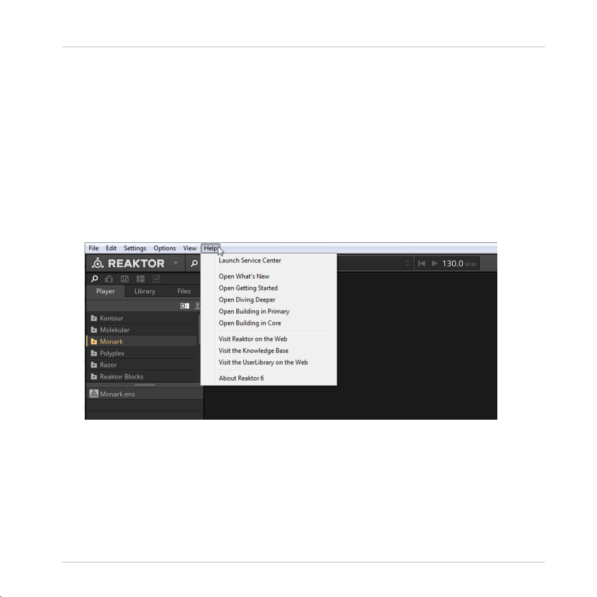
To access the REAKTOR 6 documentation, open the Help menu in the REAKTOR menu
►
bar:
REAKTOR Blocks - Manual - 7
Page 8
Welcome to REAKTOR Blocks
About the Blocks Documentation
1.1.1 Info Hints
Blocks features comprehensive information about the Blocks, their parameters and inputs and
outputs in the application. You can view this information in the form of tooltips (called Info
Hints in REAKTOR).
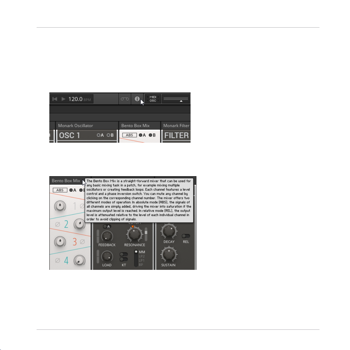
To show the Info Hints in REAKTOR, enable the Show Info Hints option in the Toolbar.
►
Info Hints are available for each entire Block, the individual parameters, as well as the inputs
and outputs.
To view the Info Hint for a Block, place the mouse over its header:
►
REAKTOR Blocks - Manual - 8
Page 9
About the Blocks Documentation
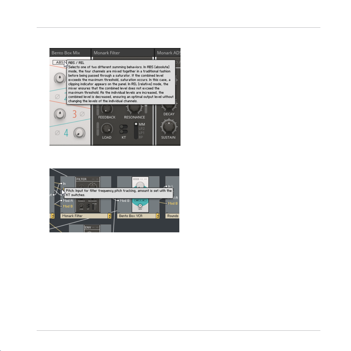
To view the Info Hint for a parameter, place the mouse over its Panel control:
►
To view the Info Hint for an input or output, place the mouse over the port in the Struc-
►
ture.
Welcome to REAKTOR Blocks
REAKTOR Blocks - Manual - 9
Page 10

Welcome to REAKTOR Blocks
About the Blocks Documentation
1.1.2 Blocks Framework Manual
In every Block, a sophisticated framework provides the infrastructure needed to bring together
the user interface, the unified connection scheme, and the underlying signal processing.
To support builders who want to contribute new Blocks to the format, an elaborate building
template has been created and uploaded to the REAKTOR User Library on our website.
The template includes all components needed to create fully compatible Blocks based on your
own designs.
It features a comprehensive manual that explains all the specifics of the framework, allowing
for a smooth transition into building your own Blocks.
REAKTOR Blocks - Manual - 10
Page 11
Welcome to REAKTOR Blocks
About the Blocks Documentation
1.1.3 Manual Conventions
This section introduces you to the signage and text highlighting used in this manual.
• Text appearing in (drop-down) menus (such as Open…, Save as… etc.) and paths to locations on your hard disk or other storage devices is printed in italics.
• Text appearing elsewhere (labels of buttons, controls, text next to checkboxes etc.) is
printed in blue. Whenever you see this formatting applied, you will find the same text appearing somewhere on the screen.
• Important names and concepts are printed in bold.
• References to keys on your computer’s keyboard you’ll find put in square brackets (e.g.,
“Press [Shift] + [Enter]”).
Single instructions are introduced by this play button type arrow.
►
Results of actions are introduced by this smaller arrow.
→
Furthermore, this manual uses particular formatting to point out special facts and to warn you
of potential issues. The icons introducing these notes let you see what kind of information is to
be expected:
The speech bubble icon indicates a useful tip that may often help you to solve a task
more efficiently.
The exclamation mark icon highlights important information that is essential for the given context.
The red cross icon warns you of serious issues and potential risks that require your full
attention.
REAKTOR Blocks - Manual - 11
Page 12
1.2 Where to Start?
Welcome to REAKTOR Blocks
Where to Start?
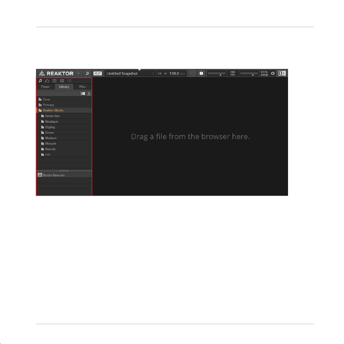
Blocks in REAKTOR 6
Blocks is part of the REAKTOR Library, which can be found in the Browser tab of the Side
Pane. The available Blocks are organized in folders, grouping them into different lines:
• Bento Box: The core components of a modular synthesizer, with special features geared
towards advanced applications.
• Boutique: Boutique Blocks take inspiration from the great synthesizers of the past, bringing the best of the history of synthesis to Blocks.
• Digilog: Digilog Blocks are utilities used to create complex rhythms, process notes, and
provide structure in patches.
• Driver, Monark, Rounds: Components from well-known NI products, ready to be integrated
in your patches.
• Modern: Modern Blocks are state-of-the-art-modules with a contemporary twist.
REAKTOR Blocks - Manual - 12
Page 13
Welcome to REAKTOR Blocks
Where to Start?
• Util: These utility Blocks are the modules that help make larger patches possible.
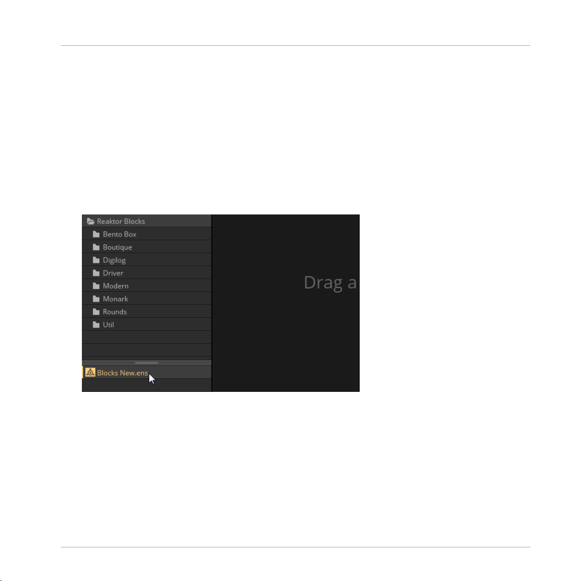
The ‘New’ Ensemble
Ensembles are the basic project files in REAKTOR that hold all relevant information of a session. Blocks patches are based on a dedicated ‘New’ Ensemble, containing a few basic modules that are often used to support patches in terms of note input, clocking, and audio output.
More importantly, this Ensemble includes optimizations for the automation handling and the
Panel view that are required for Blocks.
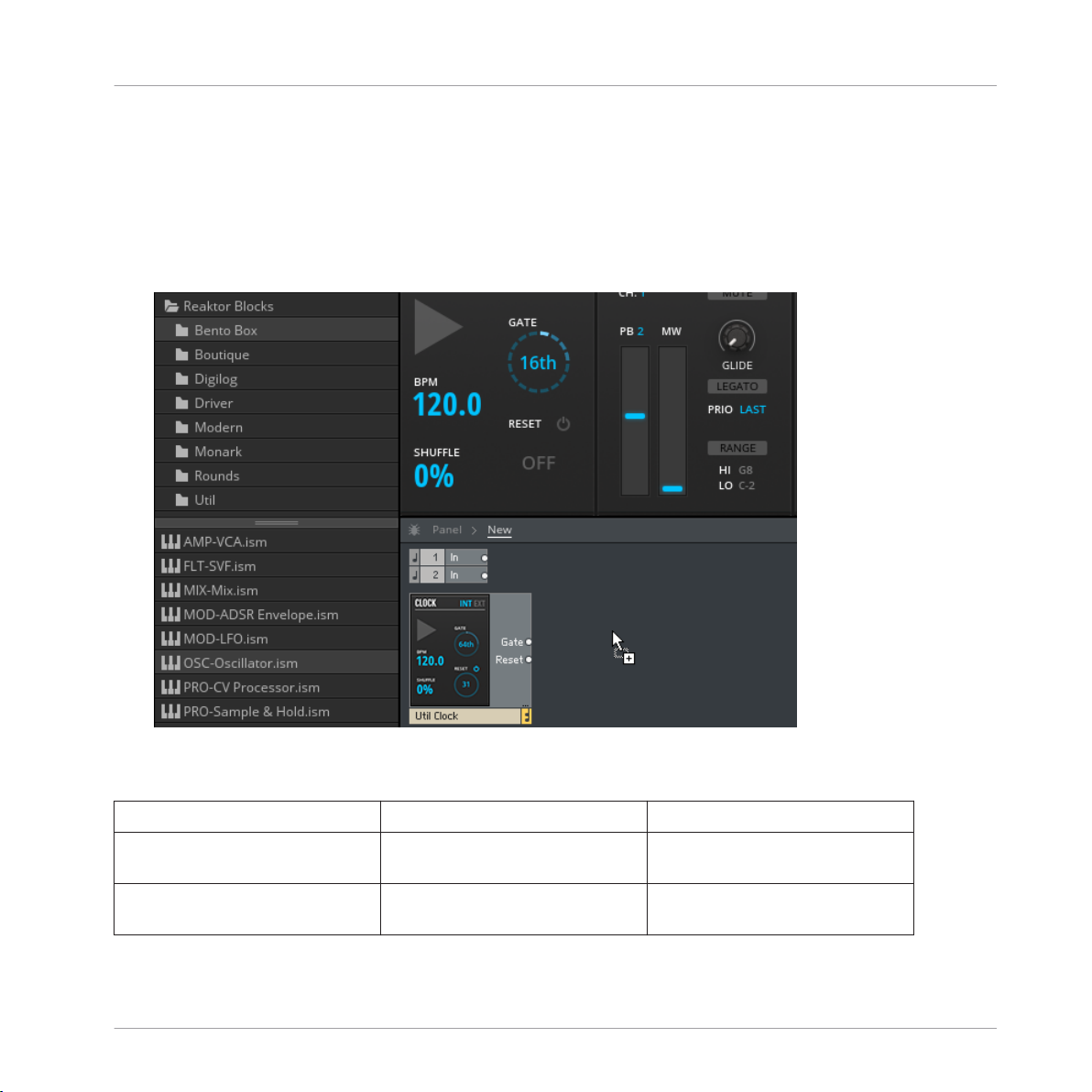
To open the ‘New’ Ensemble, select the Reaktor Blocks folder in the Library and double-
►
click on the Blocks New.ens Ensemble in the lower section of the Browser (alternatively,
you can click and drag it into REAKTOR’s main area).
REAKTOR Blocks - Manual - 13
Page 14
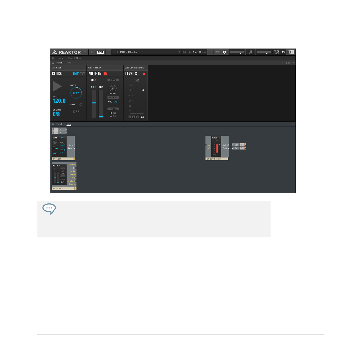
A new Ensemble opens, specifically set up for hosting Blocks patches.
→
Welcome to REAKTOR Blocks
Where to Start?
REAKTOR Blocks comes with a selection of pre-built patches (REAKTOR Ensembles)
and many presets (REAKTOR Snapshots) that are ready to be used in your music and
sound design projects. These Ensembles can be directly accessed from the MASCHINE
or KOMPLETE KONTROL Browser, or you can load them from the Reaktor Blocks folder
in the Player tab of the REAKTOR Browser (see section ↑3, Patching in Blocks).
REAKTOR Blocks - Manual - 14
Page 15

Welcome to REAKTOR Blocks
Further Reading
1.3 Further Reading
If you are new to modular synthesis, or want to expand your knowledge about patching techniques and the technology involved, the following online resources can be of great help.
The websites linked below are owned and operated by third parties. The links are provided for your information and convenience only. Native Instruments has no control over
the contents of any of the linked websites and is not responsible for these websites or
their content or availability.
• Sound On Sound Synthesizer Secrets: This extensive collection of excellent articles by
Gordon Reid covers many different synthesis techniques, explaining how they can be used
to create classic synthesizer sounds or mimic acoustical instruments.
• Rob Hordijk’s Synthesis Workshops: Rob Hordijk’s Synthesis Workshops are among the
best reads on sound synthesis available online. The articles and tutorials are very well
structured and cover synthesizer theory, history, and practice in great detail.
• Basics of Sounds Synthesis: Another helpful resource from Rob Hordijk, covering some of
the more basic topics from his Synthesis Workshops in a concise manner. This is especially useful as an introductory document for beginners.
• Advanced Programming Techniques for Modular Synthesizers: This online book by James
J. Clark explains many different advanced synthesis methods and how they can be patched up with a modular synthesizer.
• Muffwiggler Forum: Renowned not only for its odd name, the largest online community for
modular synthesis is undoubtedly the central hub of the scene, and a useful source of information. It is highly recommended to use the search engine, which is very well-featured.
REAKTOR Blocks - Manual - 15
Page 16

Basic Workflow
2 Basic Workflow
In Blocks, you use wires to connect any number of individual Blocks to form a patch, a higherlevel structure that constitutes a musical instrument, a sequencer, an effect, or any combination thereof. Each Block takes on a specific role in this structure.
This does not mean that each Block will always perform the same function in every patch.
While they all have their intended purpose, Blocks can be misused in interesting ways. There
are no wrong connections in Blocks, and unusual patches will often lead to surprising results.
Technically, Blocks are REAKTOR Instruments (REAKTOR .ism file format), and a patch consisting of multiple Blocks is hosted in a REAKTOR Ensemble (REAKTOR .ens format). Connections are made in the Structure, while the parameters are controlled on the Panel. The Panel
order is independent from the Structure, so the arrangement can be optimized for playing with
your Blocks patch.
REAKTOR Blocks - Manual - 16
Page 17
Basic Workflow
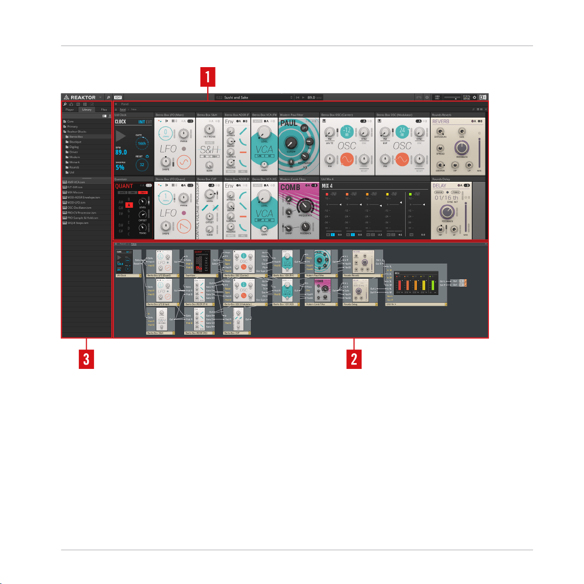
Overview over a Blocks patch in REAKTOR
(1) Panel: The Panel is located in REAKTOR’s main area and hosts the control interfaces of the
Blocks in your Ensemble. This is where you change the parameters and tweak your sounds.
(2) Structure: The Structure is also located in REAKTOR’s main area and hosts the connections
of the Blocks in your Ensemble. This is where you make connections between the inputs and
outputs and set up the signal flow of your patch.
(3) Side Pane: The Side Pane to the left of the main area hosts the Browser and additional settings like Snapshots (see section ↑2.3.2, Storing and Recalling Snapshots).
REAKTOR Blocks - Manual - 17
Page 18
Basic Workflow
Play Mode vs. Edit Mode
2.1 Play Mode vs. Edit Mode
You can play your patch and control its parameters in REAKTOR’s Play mode, however if you
want to change the Structure of your patch or some of its advanced settings, you have to enable Edit mode.
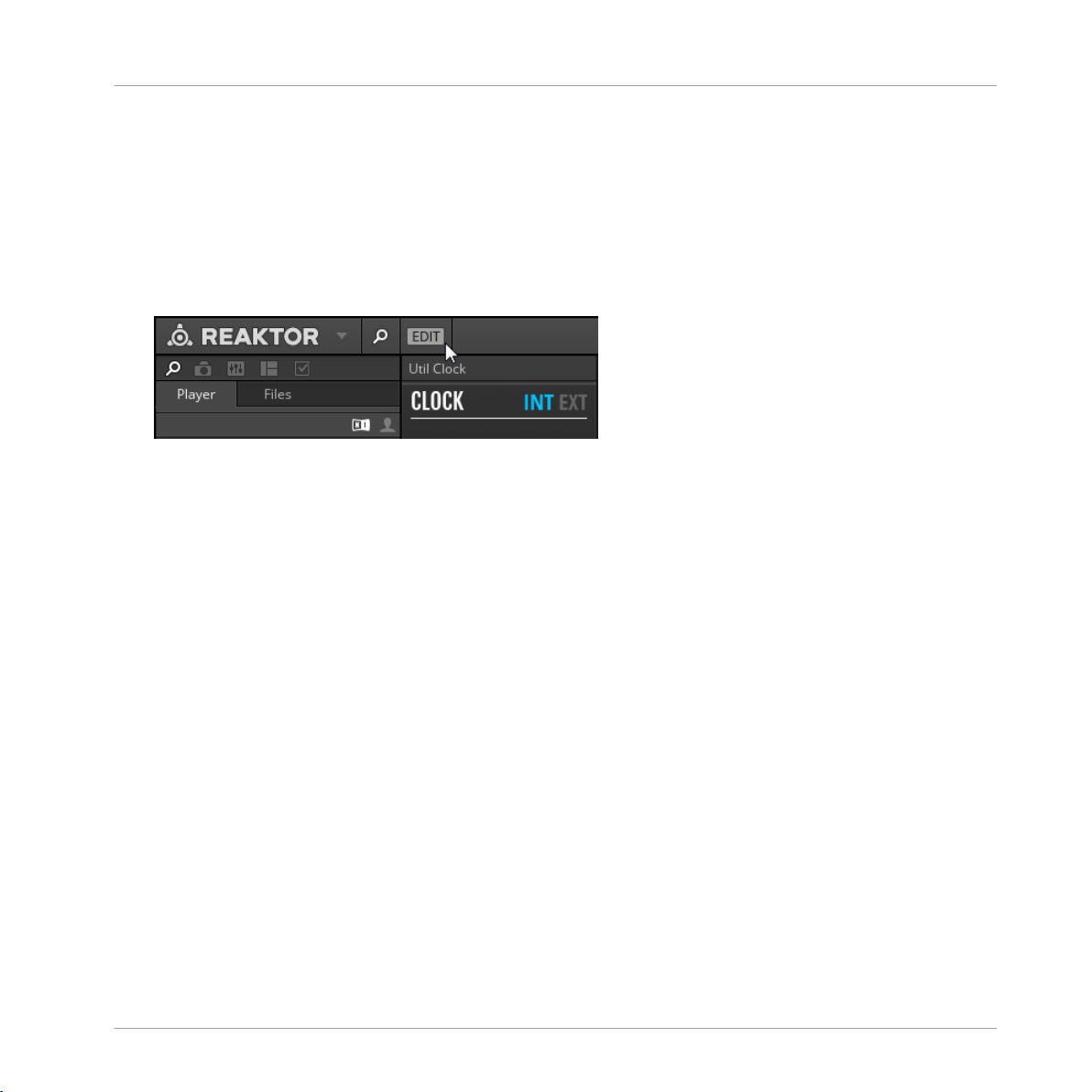
To toggle Edit Mode on or off, click on the EDIT button in REAKTOR's toolbar.
►
REAKTOR Blocks - Manual - 18
Page 19
Basic Workflow
Navigating between Panel and Structure
2.2 Navigating between Panel and Structure
You can switch between the Panel and the Structure using so-called Breadcrumps in the navigation bar at the top of REAKTOR’s main area.
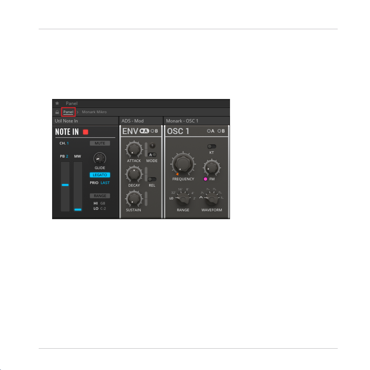
To view the Panel, click on the Panel Breadcrump in the navigation bar.
►
REAKTOR Blocks - Manual - 19
Page 20
Navigating between Panel and Structure
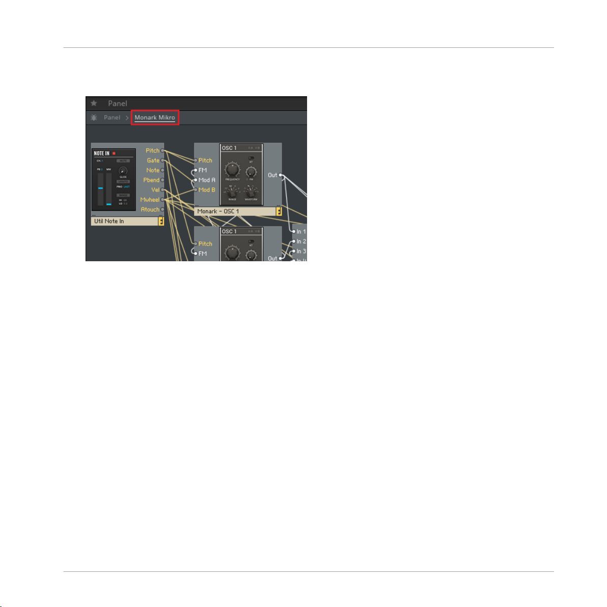
To view the Structure, click on the Breadcrump carrying the name of the Ensemble in the
►
navigation bar.
Basic Workflow
REAKTOR Blocks - Manual - 20
Page 21

Basic Workflow
Navigating between Panel and Structure
You can also use REAKTOR’s split view to view both the Panel and the Structure at the same
time:
A patch in REAKTOR Blocks, viewed in split view
REAKTOR Blocks - Manual - 21
Page 22

Navigating between Panel and Structure
To enable split view, click on the Horizontal Split or Vertical Split buttons in the upper-
►
right corner of REAKTOR’s main area.
Basic Workflow
REAKTOR Blocks - Manual - 22
Page 23

Basic Workflow
Saving Patches and Parameter Settings
2.3 Saving Patches and Parameter Settings
All connections between Blocks and their arrangement in the Structure are saved in the Ensemble, so you have to save a new Ensemble for each of your patches (see section ↑2.3.1, Sav-
ing and Loading Ensembles).
The parameter settings on the Panel can be saved in presets, called Snapshots in REAKTOR.
You can create global Snapshots for all Blocks in a patch at once, on the Ensemble level, or
individual Snapshots for each Block, on the Instrument level. This allows you to save several
sets of settings for a patch and recall them in an instant (see section ↑2.3.2, Storing and Re-
calling Snapshots).
REAKTOR Blocks - Manual - 23
Page 24

Basic Workflow
Saving Patches and Parameter Settings
2.3.1 Saving and Loading Ensembles
In the REAKTOR stand-alone application, you can save and load Ensembles from the main
menu in the Tool Bar.
To open the main menu, click on the arrow next to the REAKTOR logo.
►
Alternatively, you can use the Files tab in the REAKTOR Browser to browse for your Ensembles and load them by drag and drop, or by double-clicking.
REAKTOR Blocks - Manual - 24
Page 25

Basic Workflow
Saving Patches and Parameter Settings
Saving and Loading Ensembles in the REAKTOR Plug-in
When you are using the REAKTOR plug-in in Edit Mode to work on the Structure of a Blocks
patch, the Ensemble is modified in such way that the changes are not saved in the host sequencer’s project. In this case, the Save Ensemble button in the Toolbar turns red, indicating
that these changes will be lost when closing the project:
The red Save Ensemble button
To preserve the changes you have made, you need to create a local copy of the Ensemble. A
link to this local copy is saved in the host sequencer’s project and the Ensemble will be automatically loaded the next time you open the project. REAKTOR allows for automatic saving of
this local copy every time you save the host sequencer’s project. This way, you do not have to
keep track of the save status of the Ensemble as long as your host sequencer’s project is saved
correctly.
To save a local copy of your Ensemble and enable automatic saving:
1. Click on the Enable Automatic Saving with Host button in the Toolbar.
REAKTOR Blocks - Manual - 25
Page 26

Basic Workflow
Saving Patches and Parameter Settings
2. In the file dialog, choose the desired location and name for the local copy of your Ensemble and click Save.
The Enable Automatic Saving with Host button lights up, indicating that automatic saving
→
of your Ensemble is now enabled. The local copy of the Ensemble is saved every time you
save your host sequencer’s project, and will be automatically loaded the next time you
open the project.
REAKTOR Blocks - Manual - 26
Page 27

Basic Workflow
Saving Patches and Parameter Settings
2.3.2 Storing and Recalling Snapshots
Snapshots, which are REAKTOR's sound preset format, enable you to store and recall the state
of your Instrument's or Ensemble’s Panel controls. When you recall a Snapshot, all the Instrument’s or Ensemble’s Panel controls are restored to the state they were in when the Snapshot
was originally created. You can use this to store the parameter settings of entire Blocks patches (Ensemble) or individual Blocks (Instruments).
The connections between Blocks in the Structure are not stored in Snapshots. They are
saved in the Ensemble, which means that changes to the Structure of a patch will affect
all Snapshots for the Ensemble.
You can view and edit the Snapshots in the Snapshots tab of the Side Pane.
To access the Snapshots tab, go to the Side Pane and click on the Snapshots icon.
►
REAKTOR Blocks - Manual - 27
Page 28

Basic Workflow
Saving Patches and Parameter Settings
Recalling Snapshots
The Snapshots tab in the Side Pane shows either the Snapshots for the Ensemble or for an
individual Block.
To view the Snapshots for the Ensemble, including all settings of the included Blocks,
►
click somewhere in the background of the Structure.
The Side Pane shows all Snapshots saved for the Ensemble, indicated by the menu on
→
top of the Snapshots tab.
To view the Snapshots for an individual Block, click on the header of the Block so it is
►
highlighted.
REAKTOR Blocks - Manual - 28
Page 29

Saving Patches and Parameter Settings
The Side Pane shows all Snapshots stored for the Block, indicated by the menu on top of
→
the Snapshots tab.
Alternatively, you can select between viewing the Snapshots for the Ensemble or any of
►
the included Blocks by using the Select Instrument for Snapshot menu at the top of the
Snapshots tab.
Basic Workflow
REAKTOR Blocks - Manual - 29
Page 30

Basic Workflow
Saving Patches and Parameter Settings
You can also recall Ensemble Snapshots from the Snapshot menu in the Toolbar. This will recall the stored parameter settings for all Blocks included in the Ensemble.
The Snapshot menu in the Toolbar
REAKTOR Blocks - Manual - 30
Page 31

Saving Patches and Parameter Settings
Storing Snapshots
Storing and editing Snapshots can be done from the Snapshots tab in the Side Pane.
In order to be able to store and edit Snapshots, enable Edit Mode by clicking on the EDIT
►
button in the Toolbar.
At the bottom of the Snapshot pane are three buttons for storing Snapshots:
Basic Workflow
The buttons to Add, Store, and Insert Snapshots
REAKTOR Blocks - Manual - 31
Page 32

Saving Patches and Parameter Settings
• Add: Creates a new Snapshot with the current settings of your Instrument at the end of
the Snapshot list.
• Store: Overwrites the currently highlighted Snapshot with the current settings of your Instrument.
• Insert: Creates a new Snapshot with the current settings of your Instrument directly after
the currently highlighted Snapshot, moving any other Snapshots down one slot in order to
make space.
Snapshots are stored in the Ensemble, so the Ensemble needs to be saved in order to
make changes to the Snapshots permanent.
Basic Workflow
REAKTOR Blocks - Manual - 32
Page 33
Adding Blocks to a Patch
2.4 Adding Blocks to a Patch
Blocks can be added to a patch by drag and drop from the Library in the REAKTOR Browser.
To add a new Block to the Ensemble, drag the corresponding Instrument from the REAK-
►
TOR Library into the Structure.
Basic Workflow
All Blocks are associated with a specific category that hints at the Block’s most common usage. The category is part of the file name: <category>-<Block name>.ism
AMP Amplifiers .. control the amplitude of signals.
EFX Effects .. process audio signals in interest-
ing ways.
FLT Filters .. alter the frequency content of
signals.
REAKTOR Blocks - Manual - 33
Page 34

Adding Blocks to a Patch
INT Integration .. provide the means to sync and
control Blocks externally.
MIX Mixers .. add multiple signals together.
MOD Modulators .. generate modulation signals that
can be used to control other
Blocks.
OSC Oscillators .. generate audio signals that can
be further processed with other
Blocks.
PRO Processors .. provide the means to alter modu-
lation signals in interesting ways.
SEQ Sequencers .. generate or process pitch, gate,
and modulation signals.
AUX Auxiliary (Blocks) .. provide useful extra functions.
Basic Workflow
REAKTOR Blocks - Manual - 34
Page 35

Basic Workflow
Organizing and Arranging Blocks
2.5 Organizing and Arranging Blocks
Blocks adapts the REAKTOR interface paradigm, which is based on a Structure and a Panel
view. Connections are made in the Structure, while the parameters are controlled on the Panel.
The arrangements of the Blocks in both views are independent. This means that you can organize the Blocks in Structure view to achieve the best possible overview over your signal flow,
while setting up a different arrangement in Panel view that suits your way of playing with the
parameters.
Arranging Blocks in the Structure
In the Structure, Blocks can be freely arranged, supported by thumbnail pictures and REAKTOR’s flexible wiring system. Blocks can be placed on top of each other, however it is recommended to give each Block its own dedicated space in the Structure to maintain a better overview. The wires connecting the Blocks are automatically laid out in the shortest possible path.
If a wire crosses a Block, the overlapping portion of the wire is hidden behind the Block.
REAKTOR Blocks - Manual - 35
Page 36

To highlight all wires connected to a Block, including those being hidden behind other
►
Blocks, select it.
Basic Workflow
Organizing and Arranging Blocks
REAKTOR Blocks - Manual - 36
Page 37

Moving a block to a new position in the Structure is done by drag and drop.
1. Click on the Block you want to move and keep the mouse button pressed.
Basic Workflow
Organizing and Arranging Blocks
REAKTOR Blocks - Manual - 37
Page 38

2. Drag the Block to its new position in the Structure.
Basic Workflow
Organizing and Arranging Blocks
REAKTOR Blocks - Manual - 38
Page 39

3. Release the mouse button to place the Block in its new position.
Basic Workflow
Organizing and Arranging Blocks
REAKTOR Blocks - Manual - 39
Page 40

Basic Workflow
Organizing and Arranging Blocks
Arranging Blocks on the Panel
On the Panel, the Blocks are organized in a virtual rack that consists of as many rows as you
need. All rows of Blocks have the same, fixed height. The width of the rows is determined by
the number of Blocks you add to them. Blocks can be conveniently rearranged by drag and
drop:
To place a Block to the left of a particular Block, click on its header and drag it onto the
►
left half of this Block.
REAKTOR Blocks - Manual - 40
Page 41

Organizing and Arranging Blocks
To place a Block to the right of a particular Block, click on its header and drag it onto the
►
right half of this Block.
Basic Workflow
REAKTOR Blocks - Manual - 41
Page 42

Basic Workflow
Organizing and Arranging Blocks
The only exception is if you want to place a Block to the right of the rightmost Block in an
incomplete row.
In this case, click on the Block’s header and drag it onto the right half of the empty
►
space next to the rightmost Block.
REAKTOR’s Panelsets allow you to save multiple Panel configurations for a patch and
recall them at an instant (see REAKTOR 6 Diving Deeper for more information).
REAKTOR Blocks - Manual - 42
Page 43

Patching in Blocks
3 Patching in Blocks
Patching in Blocks is done by making connections in the Structure (see section ↑3.1, Making
Connections), controlling parameters on the Panel (see section ↑3.2, Panel Controls), and rout-
ing modulation signals to individual parameters (see section ↑3.3, Modulation Routing). If you
are familiar with modular synthesizers, you can adapt your favorite patching strategies to
Blocks right away, learning the specific features of the Blocks as you go along.
If you are new to modular synthesis, the pre-built Ensembles provided in the Player tab of the
REAKTOR Browser can serve as a starting point. By playing with the settings and making yourself familiar with the Structures you can get a feel for the Blocks used in these patches and
how they are combined.
To load one of the pre-built Ensembles, click and drag it from the Browser into the main
►
area of REAKTOR (alternatively, you can double-click on it).
REAKTOR Blocks - Manual - 43
Page 44

The Ensemble loads, ready to be played with.
→
To learn more about how the Blocks are connected, go to the Ensemble Structure by
►
clicking on the New Breadcrump in the Ensemble navigation bar.
Patching in Blocks
REAKTOR Blocks - Manual - 44
Page 45

The Structure opens, allowing you to view and edit the connections between the Blocks.
→
Alternatively, you can use REAKTOR’s split view as described in section ↑2, Basic Work-
flow.
Patching in Blocks
REAKTOR Blocks - Manual - 45
Page 46

Patching in Blocks
Making Connections
3.1 Making Connections
One of the most important features of Blocks is the universal connectivity between all of them.
You can connect any output to any input and achieve predictable results, regardless of which
Blocks are connected together.
For general information about the different types of inputs and outputs see section ↑4,
Connections and Signals. Information about how the individual inputs and outputs re-
late to the functionality of a Block can be found in the REAKTOR Info Hints (see section
↑1.1, About the Blocks Documentation).
To establish a connection between two Blocks, an output has to be connected to an input, or
vice versa:
1. Click on the output you want to connect and keep the mouse button pressed.
2. Drag the mouse onto the input you want to connect and release the mouse button.
REAKTOR Blocks - Manual - 46
Page 47

The connection is established, indicated by a wire going from the output to the input.
→
Patching in Blocks
Making Connections
REAKTOR Blocks - Manual - 47
Page 48

Patching in Blocks
3.2 Panel Controls
Each line of Blocks has its own characteristic design, making it easy to tell one from another.
However, most of the Panel controls follow the same interface paradigm, which allows you to
adjust and play the parameters in an intuitive manner. Below, the most common Panel controls are explained briefly.
Find detailed information about each Panel control in the REAKTOR Info Hints (see section ↑1.1.1, Info Hints).
Panel Controls
Common Blocks Panel controls
(1) Knob: Knobs are the most common Panel control in Blocks. Click and drag a knob up and
down to change its value. The current value is shown below the knob while adjusting the parameter. Press [strg] (Windows) or [cmd] (OS X) and double-click on them to reset their value
to default.
REAKTOR Blocks - Manual - 48
Page 49

Patching in Blocks
(2) Circular value control: These controls can be adjusted like Knobs, by clicking and dragging
them up and down. They feature a large value display and are used for parameters like oscillator pitch and waveform selection. For pitch, a dual control is used, with coarse tuning at the
top and fine tuning at the bottom. Press [strg] (Windows) or [cmd] (OS X) and double-click on
them to reset their value to default.
(3) Modulation buttons: The A and B buttons are used for routing modulation signals in a Block.
See section ↑3.3, Modulation Routing for more information.
(4) Symbol mode control: These controls are used to select between different modes of a function, in this case different envelope shapes on the Bento Box Env. Click on the symbol to step
through the available modes. The symbol reflects the current setting.
(5) Large knob: Large knobs are used for the most important parameters of a Block, for example
the FREQUENCY control of the Comb filter.
(6) Global control: The options at the top of a Block select between different modes of operation, like key tracking for the OSC 5 in this case.
(7) Label control: On some Blocks, the labels of controls can be clicked to change a related
parameter. On the OSC 5, the waveform label selects alternate waveforms for each of the intervals.
Panel Controls
(8) Fader: Faders are used as an alternative to knobs and can be adjusted in the same way, by
clicking and dragging them up and down. The current value is shown above the fader while adjusting the parameter. Press [strg] (Windows) or [cmd] (OS X) and double-click on them to reset their value to default.
(9) Modulation depth slider: The modulation depth sliders control the amount of modulation applied to the associated parameter. See section ↑3.3, Modulation Routing for more information.
(10) Button: Buttons switch between two alternate options or toggle single functions on or off.
You can change their value by clicking on them. If the button switches between alternate options, the label will change accordingly. If it toggles a single function on or off, the on-state is
highlighted.
(11) Momentary button: These buttons are used for Gate and Reset functions. They light up
when a gate arrives at the associated input and triggers the function. You can also click on
them to manually set off the function, like starting the envelope on the Bento Box Env.
REAKTOR Blocks - Manual - 49
Page 50

Patching in Blocks
(12) Control mode button: Some controls, like PHASE, FM, and SYNC on the Bento Box OSC,
feature auxiliary buttons next to their labels that allow you change their mode of operation.
Panel Controls
REAKTOR Blocks - Manual - 50
Page 51
Patching in Blocks
Modulation Routing
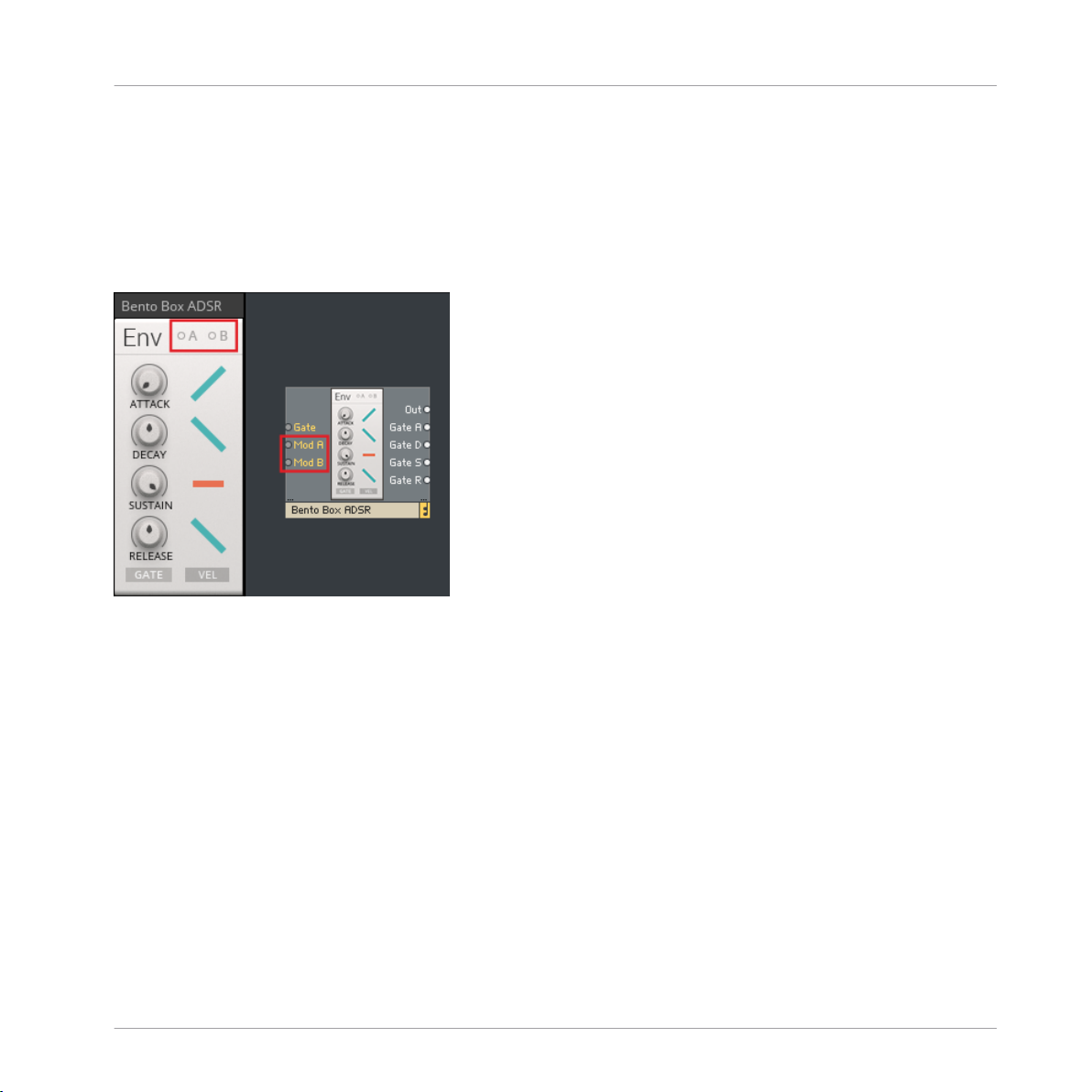
3.3 Modulation Routing
Every Block has two Modulation Buses A and B, represented by the two buttons A and B in the
upper-right corner of the Panel. These buttons correspond to the Mod A and Mod B inputs
found in Structure View:
The Modulation Buses in REAKTOR Blocks
REAKTOR Blocks - Manual - 51
Page 52

Patching in Blocks
Modulation Routing
The Modulation Buses distribute the signals arriving at the Mod A and Mod B inputs of a Block
to all parameters that can be modulated. You can set the amount of modulation applied to
each parameter with dedicated modulation depth sliders:
Click the A or B button to show the modulation depth sliders of the corresponding Modu-
►
lation Bus for each parameter.
The modulation depth sliders are shown for all parameters that can be modulated.
→
REAKTOR Blocks - Manual - 52
Page 53

Patching in Blocks
Modulation Routing
The modulation depth sliders set the amount of modulation from the currently selected
►
Modulation Bus. All modulation depth sliders are bipolar, meaning that positive (non-inverted) or negative (inverted) modulation can be applied.
The A and B buttons include a signal indicator that displays incoming modulation signals. It
lights up red for positive values and blue for negative values. If you turn up the modulation
amount for a parameter, the modulation will also be displayed as a moving arrow next to the
Panel control.
If no modulation signal is present at the Mod A or Mod B input, the corresponding button is grayed out. However, you can still click the buttons and view or change modulation amounts for parameters. The settings in the Panel are independent from the connections, so you can swap modulation sources while keeping the modulation amounts
for the parameters.
REAKTOR Blocks - Manual - 53
Page 54

Patching in Blocks
Modulation Routing
Example
In the following example, the Bento Box LFO is connected to the Mod A input of the Bento Box
Env:
Routing modulation signals in REAKTOR Blocks
• The A button on the Bento Box Env is pressed. The modulation depth sliders appear for
all parameters that can be modulated.
• The A signal indicator is lighting up blue, displaying a negative value of the modulation
signal coming from the Bento Box LFO. Note the matching color of the output signal indicator next to the LFO label on the Bento Box LFO.
• Modulation Bus A is routed to a single parameter on the Bento Box Env, in this case DE-
CAY. The modulation depth slider next to the DECAY knob is turned up, allowing the mod-
ulation signal from the Bento Box LFO to control the decay time of the envelope.
• The arrow next to the DECAY knob shows the momentary position of the modulation relative to the knob setting.
REAKTOR Blocks - Manual - 54
Page 55

Connections and Signals
4 Connections and Signals
In order to achieve the desired level of flexibility, there is no distinction between different
types of signals in REAKTOR Blocks. All connections are being made with signals within the
range of -1 to +1. This allows you to connect any output to any input, without having to worry
about signal type or value range.
Patching Feedback
There are also no constraints in regards to making feedback connections across any number of
modules. However, if you want to make a feedback connection between an input and an output
from the same Block, an additional Block needs to be patched in between.
Aside from the Bento Box Mix, which allows you to add the feedback signal to an existing input
signal, the Bento Box CVP is particularly well suited for this task, providing the means for further processing of the feedback signal.
Connecting the BP output of the Bento Box SVF to its FM input
Input and Output Types
Different Blocks require different types of inputs and outputs. Since all signals sent between
Blocks fall into the same range, it is necessary to determine how values within that range are
converted into a predictable result, depending on what type of input they have been connected
to.
There are 6 different input and output types:
• General inputs and outputs (see section ↑4.1, General Inputs and Outputs)
REAKTOR Blocks - Manual - 55
Page 56

◦ In (input, multiple inputs are numbered)
◦ Out (output, multiple outputs are numbered or labeled with their respective function)
• Modulation (see section ↑4.2, Modulation)
◦ Mod A (modulation bus A, input only)
◦ Mod B (modulation bus B, input only)
◦ FM (frequency modulation, input only)
• Pitch (see section ↑4.3, Pitch)
• Gate (see section ↑4.4, Gate)
• Reset (see section ↑4.5, Reset)
• Sync (see section ↑4.6, Sync)
Connections and Signals
REAKTOR Blocks - Manual - 56
Page 57

Connections and Signals
General Inputs and Outputs
4.1 General Inputs and Outputs
The In and Out ports can be used for all kinds of signals, depending on the Blocks’ functionality and application. All inputs and outputs operate at audio rate and in the range of -1 to +1.
The general input and output on the Comb filter
If a Block has multiple inputs, for example the Bento Box Mix, the inputs are numbered: In 1,
In 2, In 3, and so on.
The inputs on the Bento Box Mix
In some cases, inputs or outputs are labeled depending on their specific function. For example, the Bento Box Env has four Gate outputs that send a gate high signal as long as the corresponding envelope stage is active:
REAKTOR Blocks - Manual - 57
Page 58

Connections and Signals
General Inputs and Outputs
The Gate outputs on the Bento Box Env
• Gate A (gate high during attack)
• Gate D (gate high during decay)
• Gate S (gate high during sustain)
• Gate R (gate high during release)
The same applies to oscillators with multiple waveform outputs or filters with separate outputs
for each filter mode, for example the the Bento Box SVF:
The filter mode outputs on the Bento Box SVF
• Out (main output with switchable filter mode)
• LP Out (low pass mode output)
• BP Out (band pass mode output)
• HP Out (high pass mode output)
REAKTOR Blocks - Manual - 58
Page 59

Connections and Signals
4.2 Modulation
The Mod A and Mod B inputs are general modulation inputs. They allow for modulation in the
full range of -1 to +1 and at any rate. Signals arriving at these inputs can be used to modulate
various different parameters on each Block (see ↑3.3, Modulation Routing for more information).
The Mod A and Mod B inputs on the Bento Box SVF
Oscillators and filters often have an additional FM input. These Frequency Modulation inputs
can be used to add modulation to the pitch of an oscillator, or the cutoff frequency of a filter.
For example, it can be used to modulate the cutoff frequency of a filter with an envelope, or to
set up multiple oscillators for FM synthesis. The corresponding Panel control sets the depth of
modulation.
Modulation
The FM input on the Bento Box SVF
REAKTOR Blocks - Manual - 59
Page 60

Connections and Signals
4.3 Pitch
Pitch inputs, which are used to control the frequency of oscillators and filters, scale an input
value between 0 and 1 up to a MIDI note value between 0 and 120. A value of 0 equals MIDI
note 0, a value of 0.5 equals MIDI note 60, and a value of 1 equals MIDI note 120.
However, this does not mean that you have to use quantized signals to control your oscillators.
If you connect an envelope to the Pitch input of an oscillator, the envelope output of 0 to 1
results in a smooth sweep ranging from MIDI note 0 to MIDI note 120 (given that no offset has
been dialed in using the frequency controls of the oscillator).
Using this range allows for convenient scaling and offsetting of pitch signals, since the range
from 0 to 1 covers exactly 10 octaves. Similar to the 1 V/Oct-standard as found on contemporary modular synthesizers, you are dealing with a value of 0.1/Oct in REAKTOR Blocks. For instance, if you want to transpose a pitch signal two octaves up, you have to add an offset of 0.2
(or 20%) to the signal.
Pitch inputs also accept signals lower than -1 and higher than +1, so pitches above and below
the specified range can be achieved, too.
Pitch
The Pitch input on the Bento Box OSC
REAKTOR Blocks - Manual - 60
Page 61

Connections and Signals
4.4 Gate
Gate inputs are used to control a variety of functions in different Blocks, from triggering enve-
lopes or advancing sequencer steps to resetting LFOs. They operate in the range of -1 to +1, so
any signal can be connected. Gate outputs usually send out a pulse wave signal in the range of
0 to 1 (except for Gate outputs that pass on velocity information, see below).
The Gate input and Gate outputs on the Bento Box Env
Gate inputs look for a positive zero crossing of the input signal. As soon the input signal rises
above 0, it is considered a gate-on message, and once the signal drops below 0, it is considered a gate-off message.
Gate
For example, you can connect the output of an LFO to the Gate input of an envelope. The LFO
has an output of -/+0.5. When its output goes above 0, this is considered a gate-on message
and the envelope is triggered and sustained. When the LFO returns to 0 or less, this is considered a gate-off message and the envelope is released.
The same applies to any Block with a Gate input: Connect the LFO to the Gate input of a sequencer, and every time the LFO travels into the positive part of its cycle, the sequencer will
advance one step. Since Gate inputs operate at audio rate like any connection in REAKTOR
Blocks, you can also replace the LFO with an audio oscillator and run the sequencer at audio
rate, creating a new interesting sound source.
Velocity
Velocity (for example on envelopes with velocity sensitivity) is derived from how far above 0 the
initial increase is. If the input leaps from 0 to 1, an envelope will be triggered at maximum
velocity. A jump from 0 to 0.5 would trigger the envelope at half velocity, and so on. Conse-
REAKTOR Blocks - Manual - 61
Page 62

Connections and Signals
quently, if you use a triangle LFO to trigger an envelope with velocity sensitivity, the output
level of the envelope will be very low: The LFO cycles above 0, but the initial increase is very
small.
Some Gate outputs (for example on the Util Note In and the Bento Box 8 Steps) include velocity information. In this case, the gate signal's amplitude varies depending on the velocity of the
played note or the corresponding sequencer step.
Gate
REAKTOR Blocks - Manual - 62
Page 63

Connections and Signals
4.5 Reset
Reset inputs function in a similar manner as Gate inputs, looking for a positive zero crossing of
the incoming signal. As soon as the input signal rises above 0, it is considered a reset gate.
However, unlike Gate inputs, negative zero crossings have no effect.
The Reset input on the Bento Box 8 Steps
Reset inputs are commonly found on sequencers (or other counting devices), for example the
Bento Box 8 Steps. Every time a positive value arrives, the sequencer is reset to the first step.
On the 8 Steps’ panel, you will notice that the RESET button lights up when a reset signal is
received.
Reset
You can use any signal to reset your sequencers, however the Reset output on the Util Clock is
specifically designed for this task. It sends out a reset signal every time it is started, and repeats it at an interval set by the RESET control on the panel. By distributing the reset signal
from the Util Clock across your patch, you can ensure that all sequencers remain synchronous.
REAKTOR Blocks - Manual - 63
Page 64

Connections and Signals
4.6 Sync
Like Gate and Reset inputs, Gate inputs look for a positive zero crossing of the incoming signal. As soon as the input signal rises above 0, a sync event is triggered. Negative zero crossings have no effect.
The Sync input on the Bento Box OSC
Sync inputs can be found on oscillators. They are used to synchronize the phase of the signal
generated by the oscillator to an external source, for example another oscillator. This is useful
for adding stability to complex FM patches with multiple operators, patching classic oscillator
sync sounds, or creating interesting new waveforms by mixing signals from multiple synced oscillators.
Sync
The Bento Box OSC's Sync input has the option to accept a special synchronization signal from
the OSC Sync outputs found on the Bento Box OSC and the Multiwave OSC. This allows for
oscillator synchronization with the best possible audio quality.
The Multiwave OSC’s Osc Sync output, connected to the Bento Box OSC’s Sync input
REAKTOR Blocks - Manual - 64
 Loading...