

Page 1

Framework Manual
Page 2

The information in this document is subject to change without notice and does not represent a
commitment on the part of Native Instruments GmbH. The software described by this document is subject to a License Agreement and may not be copied to other media. No part of this
publication may be copied, reproduced or otherwise transmitted or recorded, for any purpose,
without prior written permission by Native Instruments GmbH, hereinafter referred to as Native
Instruments.
“Native Instruments”, “NI” and associated logos are (registered) trademarks of Native Instruments GmbH.
Mac, Mac OS, GarageBand, Logic, iTunes and iPod are registered trademarks of Apple Inc.,
registered in the U.S. and other countries.
Windows, Windows Vista and DirectSound are registered trademarks of Microsoft Corporation
in the United States and/or other countries.
All other trade marks are the property of their respective owners and use of them does not imply any affiliation with or endorsement by them.
Document authored by: David Forrester
Software version: 1.0 (09/2015)
Disclaimer
Page 3

NATIVE INSTRUMENTS GmbH
Schlesische Str. 29-30
D-10997 Berlin
Germany
www.native-instruments.de
NATIVE INSTRUMENTS North America, Inc.
6725 Sunset Boulevard
5th Floor
Los Angeles, CA 90028
USA
www.native-instruments.com
NATIVE INSTRUMENTS K.K.
YO Building 3F
Jingumae 6-7-15, Shibuya-ku,
Tokyo 150-0001
Japan
www.native-instruments.co.jp
Contact
NATIVE INSTRUMENTS UK Limited
18 Phipp Street
London EC2A 4NU
UK
www.native-instruments.com
© NATIVE INSTRUMENTS GmbH, 2015. All rights reserved.
Page 4

Table of Contents
Table of Contents
1 Anatomy of a Block ...................................................................................................
1.1 System Info Macro ...................................................................................................................... 9
1.2 Panel Macro ................................................................................................................................10
1.3 Process Core Cell ........................................................................................................................ 16
1.4 A Completed Block ...................................................................................................................... 19
1.2.1 Size Macro ................................................................................................................. 11
1.2.2 A/B Buttons Macro ..................................................................................................... 12
1.2.3 Panel Elements .......................................................................................................... 13
1.2.4 Mod Ring and Mod Return ......................................................................................... 14
1.3.1 Display Clk Distributor ............................................................................................... 16
1.3.2 A and B Distributors .................................................................................................. 17
1.3.3 Smoother Attributes ................................................................................................... 17
1.3.4 Smooth + A/B Mod .................................................................................................... 17
2 Connections and Signals ...........................................................................................
2.1 Audio Rate Connections .............................................................................................................. 21
2.2 Value Range ............................................................................................................................... 22
2.3 Pitch Scaling .............................................................................................................................. 23
2.4 Gate Signals ............................................................................................................................... 24
2.5 Gate Signals and Velocity ........................................................................................................... 25
3 Panel Widgets ...........................................................................................................
3.1 Color Schemes ............................................................................................................................ 29
3.2 Template Blocks ......................................................................................................................... 31
3.3 Process Macros ........................................................................................................................... 32
3.4 Knobs ......................................................................................................................................... 33
3.1.1 Additional Knob Colors .............................................................................................. 30
3.4.1 Basic Knobs ............................................................................................................... 33
7
20
27
REAKTOR Blocks - Framework Manual - 4
Page 5

Table of Contents
3.5 Customizing Knobs ..................................................................................................................... 38
3.6 Buttons .......................................................................................................................................41
3.7 Meters ........................................................................................................................................ 46
3.4.2 Basic Knobs (Bipolar) ................................................................................................ 34
3.4.3 Modulation Knobs ...................................................................................................... 34
3.4.4 Modulation Knobs (Bipolar) ....................................................................................... 35
3.4.5 OSC Tuning ................................................................................................................ 36
3.4.6 Multiplex Knobs ......................................................................................................... 37
3.5.1 Color .......................................................................................................................... 38
3.5.2 Labels ........................................................................................................................ 39
3.5.3 Values ....................................................................................................................... 39
3.6.1 Basic Button .............................................................................................................. 41
3.6.2 Basic Color Button ..................................................................................................... 41
3.6.3 Multistate Button ...................................................................................................... 42
3.6.4 Multistate Color Button ............................................................................................. 42
3.6.5 Radio Buttons ............................................................................................................ 43
3.6.6 Radio Color Buttons ................................................................................................... 43
3.6.7 Multiplex Buttons ...................................................................................................... 44
3.6.8 Multiplex Color Buttons ............................................................................................. 44
3.6.9 A/B Buttons ............................................................................................................... 45
3.7.1 Meter Mono ................................................................................................................ 46
3.7.2 Meter Stereo .............................................................................................................. 46
4 Process Macros ........................................................................................................
4.1 Inputs ......................................................................................................................................... 49
4.2 Smoothing and Modulation .........................................................................................................52
4.3 Select and Distribute .................................................................................................................. 55
4.4 Counting .....................................................................................................................................57
48
REAKTOR Blocks - Framework Manual - 5
Page 6

4.5 Demultiplex ................................................................................................................................ 58
4.6 Outputs ...................................................................................................................................... 61
Table of Contents
REAKTOR Blocks - Framework Manual - 6
Page 7
1 Anatomy of a Block
Anatomy of a Block
The Structure of a Block
Whatever the function, all REAKTOR Blocks are built in the same way. Three distinct Macros
each carry out a particular task. The Panel Macro contains all front end elements of the Block.
The System Info Macro houses all elements which provide the necessary system and project
information. Both the Panel and System Info Macros feed into the process Core Cell. This Core
Cell is where all of the actual processing happens, making use of the signals provided to it by
both system and user.
On either side of these three Macros are the Block’s inputs and outputs. In order to maintain a
degree of familiarity for the user, these ports should always be found in the same order.
Audio inputs are always in first position, followed by Pitch/Frequency inputs, Gate/Reset inputs, and finally modulation bus inputs. Outputs are also ordered in the same way.
REAKTOR Blocks - Framework Manual - 7
Page 8
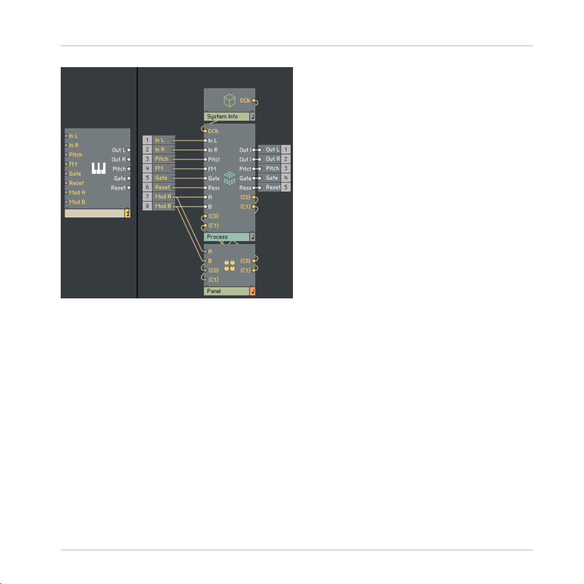
The inputs and outputs in the Block Structure
Anatomy of a Block
REAKTOR Blocks - Framework Manual - 8
Page 9
Anatomy of a Block
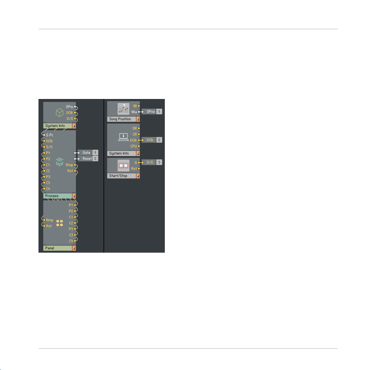
System Info Macro
1.1 System Info Macro
The System Info Macro serves to provide the Block with all necessary information from the system and project in which it resides. This might include system clocks, song position, tempo
information, random seeds, and so on.
The System Info Macro
In this example, the System Info Macro is providing the Process Core Cell with 3 signals. Audio
song position (SPos), display clock (DClk), and the master start/stop gate (S/S). These signals
are then connected directly to the Process Core Cell, where they are distributed as required.
REAKTOR Blocks - Framework Manual - 9
Page 10
Anatomy of a Block
1.2 Panel Macro
While the System Info Macro is providing the Process Core Cell with all system signals, the
Panel Macro deals with all user signals. This includes panel elements such as knobs, buttons,
text, displays, and anything else pertaining to how the Block looks and how the user can interact with it.
Panel Macro
The Panel Macro
REAKTOR Blocks - Framework Manual - 10
Page 11

Anatomy of a Block
In this example, the Panel Macro contains a number of different panel elements. The outputs
from all of these elements are connected directly to the Process Core Cell. The Panel Macro
also receives signals from the Process Core Cell. These signals are sent into the various panel
elements, where they are used to display any modulation that has been applied to that particular parameter.
In addition to all panel elements, the Panel Macro also contains 2 further Macros, A/B Buttons
and a size Macro.
1.2.1 Size Macro
Inside every Panel Macro is a size Macro. The size Macro does not contain any modules, but
instead serves to determine that Block’s panel size.
In order for all Blocks to line up correctly in panel view, all panels are made to particular dimensions. Panels should always be 252 pixels in height, but width will vary depending on the
complexity of the panel. Never the less, width should still adhere to specific values for correct
alignment.
Block widths are calculated on a grid where 1 ‘unit’ is 60 pixels, and panel widths are multiples thereof. The 4 pixel gap between instruments should also be taken into account when calculating panel width.
Panel Macro
• Panel width in pixels = number of units * 60 - 4 pixel gap.
• The smallest available width is 2 units or 116 pixels: 2 * 60 - 4 = 116
The size Macro is in fact an empty stacked Macro, and setting its width and height in the view
properties menu will determine the size of the Block’s panel. REAKTOR always creates an additional border around any panel elements, which must be taken into consideration when setting the height and width. This border will always be 8 pixels on either side, and 6 pixels at
the top and bottom, and these values should be subtracted accordingly.
REAKTOR Blocks - Framework Manual - 11
Page 12
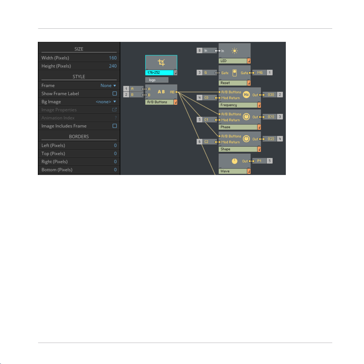
The Size Macro
Anatomy of a Block
Panel Macro
This example shows a 3 unit wide size Macro. The panel should be 176 pixels wide, and 252
pixels tall. To adjust for the border added by REAKTOR, the correct dimensions for the stacked
Macro should be Width (Pixels) = 160, and Height (Pixels) = 240.
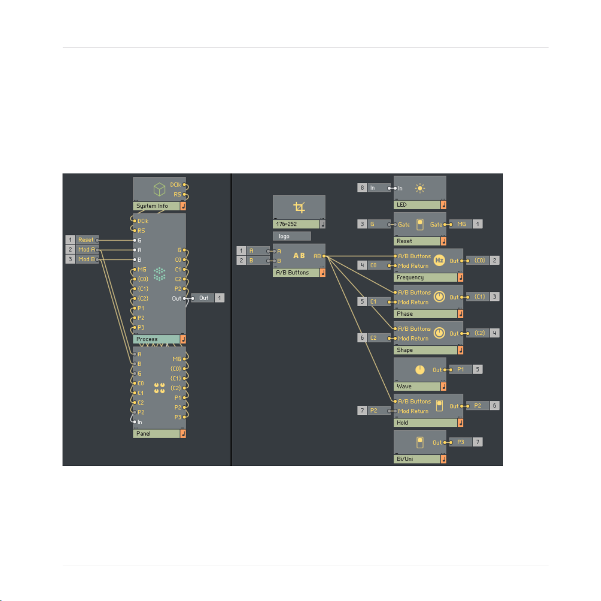
1.2.2 A/B Buttons Macro
The A/B Buttons Macro serves two purposes. When a signal is connected to a modulation bus
input, the buttons on the panel will illuminate to display the signal’s strength and polarity. The
A/B Buttons Macro also determines when the modulation sliders are visible on the panel, and
so its output should be directly connected to the A/B Buttons input of all panel elements inside of that Block.
REAKTOR Blocks - Framework Manual - 12
Page 13
Anatomy of a Block
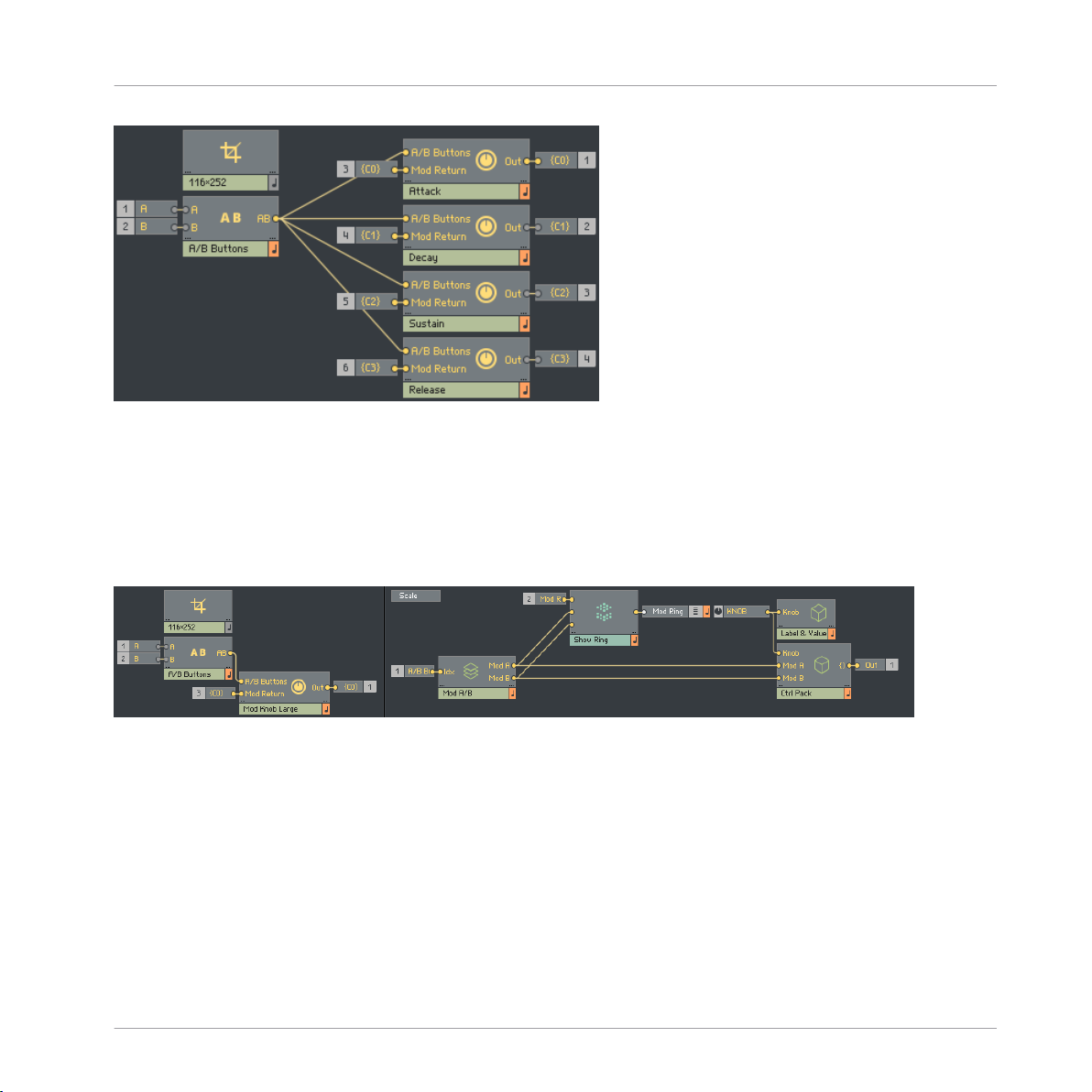
The A/B Buttons Macro, connected to Panel elements
1.2.3 Panel Elements
There is a wide variety of panel elements provided with the template, all of which are covered
in more detail in the “Panel Widgets” section. However, the most commonly found element is
the modulatable knob.
Panel Macro
The modulatable knob in the Panel Macro
The left image shows how the modulatable knob should be placed inside of the Panel Macro,
while the right image shows the inside of the modulatable knob itself. The Mod Knob Macro is
comprised of a number of different elements. Most important are the main control, and the A
and B modulation sliders. The main control is found in the first level of the Mod Knob Macro,
while the modulation sliders are to be found in the Mod A/B stacked Macro, the panel index of
which is connected to the A/B Buttons Macro as discussed in the previous section.
Other elements found in the Mod Knob Macro are the Label & Value Macro, the Ctrl Pack Macro the Mod Ring display, and the Scale picture.
REAKTOR Blocks - Framework Manual - 13
Page 14
Anatomy of a Block
The Label & Value Macro contains a label for displaying the parameter name, a value display,
as well as some additional modules which determine what is currently visible on the panel.
Here you are able to change parameter names or use a different type of value display, depending on what the knob is controlling. A variety of different Label & Value Macros are already provided with the template which can be used to replace the default one, should a different value
display be required.
The Ctrl Pack Macro packages the signals from the main control, and both modulation faders
into a single signal which is then connected directly to the Process Core Cell. These signals are
then unpacked and used to control modulation depths and so on. Further information on this
can be found in the “Smooth + A/B Mod” section.
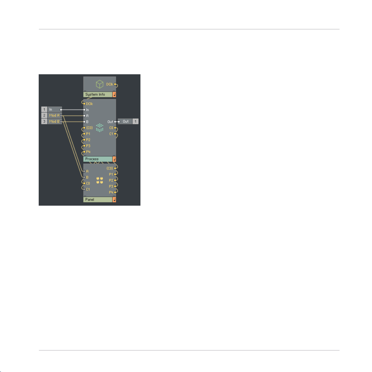
1.2.4 Mod Ring and Mod Return
The Mod Knob Macro sends all parameter values and modulation amounts into the process
Core Cell, where the actual modulation signals are scaled and summed accordingly. The result
of this summing will then be sent to wherever it is needed within the Process Core Cell. In addition, it is also routed back to the Panel Macro, and to the original panel element, where it is
displayed by the Mod Ring display.
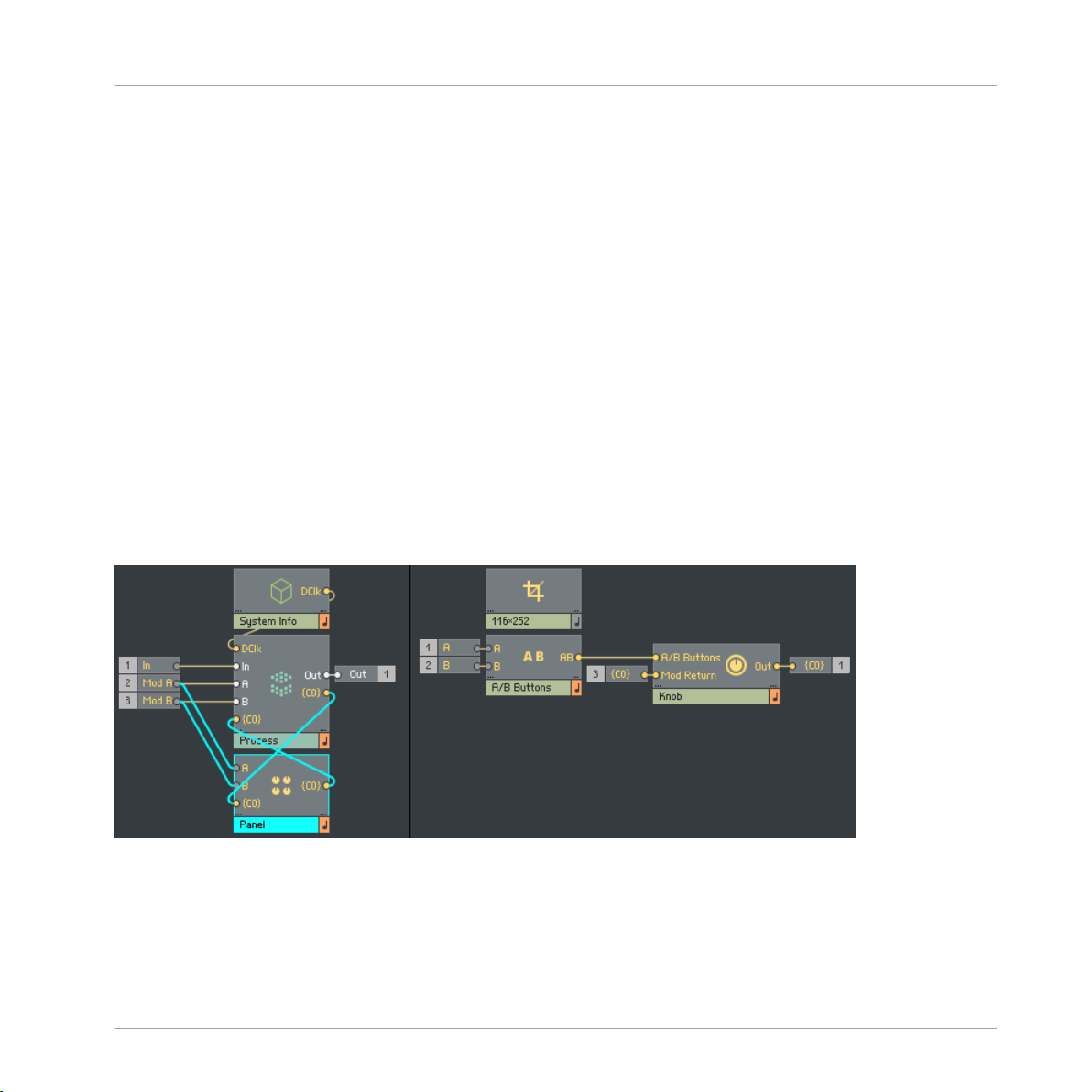
Panel Macro
Connections between the Panel Macro and the Process Core Cell
The left image shows the connections between the Panel Macro and the Process Core Cell. Parameter values are sent from the panel element via the {C0} output. All scaling of modulation
signals occur within the Core Cell, and the result is returned to the panel element via the {C0}
REAKTOR Blocks - Framework Manual - 14
Page 15

Anatomy of a Block
input. The right image shows how the Knob panel element is connected inside of the ‘Panel”
Macro. Again, parameter values are sent via the {C0} output, and the resulting modulation is
returned via the {C0} input.
Panel Macro
REAKTOR Blocks - Framework Manual - 15
Page 16
Anatomy of a Block
Process Core Cell
1.3 Process Core Cell
Both the System Info and Panel Macros are connected to the Process Core Cell, where all of
the actual signal processing occurs. The template includes several starter instruments, each of
which contains an empty Process Core Cell.
The Process Core Cell
The left side of the image shows the connections between the System Info and Panel Macros,
and the Process Core Cell. The right side of the image shows the inside of the Core Cell itself.
By default, the template Core Cell will already contain many of the ports and elements required to receive signals from the System Info and Panel Macros.
1.3.1 Display Clk Distributor
The Display Clk distribution bus sends the display rate clock, as provided by the System Info
Macro, to the Display Latch Macros. This is where ‘modulation return’ signals are clocked before being routed back to their associated panel elements. Within Blocks, modulation signals
REAKTOR Blocks - Framework Manual - 16
Page 17

Anatomy of a Block
Process Core Cell
are audio rate, however this is a far higher rate than can be displayed on the panel. Attempting
to display audio rate signals would be inefficient. Instead, before leaving the Process Core Cell
‘modulation return’ signals are latched by the display rate clock, resulting in a noticeable increase in efficiency.
1.3.2 A and B Distributors
The A and B buses distribute all signals arriving at the A and B modulation buses throughout
the entire Core Cell, where they can be used as a modulation source. Typically, a completed
block will have a number of modulatable parameters. By distributing the signals arriving at the
A and B modulation buses in this way, it helps to keep structures cleaner and more organized.
1.3.3 Smoother Attributes
Any connection between two Blocks will be at audio rate, however the connection between a
panel element and the Process Core Cell within a Block will be control rate. Therefore, some
degree of smoothing is required in order to avoid potential discontinuity in signals, audible
‘pops’, and other such undesirable results. The Smoother Attributes Macro provides the various
signals required for smoothing parameters at 2 different clock rates; 1K and 15K. These attributes can be picked up anywhere within the Process Core Cell. In addition, the template also
provides a selection of different smoothers, which will automatically pick up all relevant information provided by the Smoother Attributes Macro.
1.3.4 Smooth + A/B Mod
The Smooth + A/B Mod Macro is one of the most important Macros within the Blocks framework. This Macro serves a variety of purposes. As mentioned in the “Panel elements” section,
before being sent to the Process Core Cell the 3 values inside of a modulatable parameter are
packaged together into a single connection. The first thing the Smooth + A/B Mod Macro does
is to unpack this connection into its individual components, the main control, and the 2 modulation sliders.
The second task of the Smooth + A/B Mod Macro is to apply smoothing to the 3 signals, before
receiving, scaling, and summing any modulation signals.
REAKTOR Blocks - Framework Manual - 17
Page 18

Anatomy of a Block
Process Core Cell
The Dmux and Prep Macros
The DMux Macro is responsible for unpacking the arriving signal, while the Prep Macro deals
with smoothing of parameters, and scaling/summing of modulation signals.
The DMux Macro
Having been unpacked by the DMux Macro, the 3 signals provided by the panel element are
routed to the Prep Macro and smoothed. In addition, signals connected to the A and B modulation buses are also received here before being scaled, summed with the main control value,
and clipped to ensure the result remains within the [0, 1] range.
REAKTOR Blocks - Framework Manual - 18
Page 19
1.4 A Completed Block
Anatomy of a Block
A Completed Block
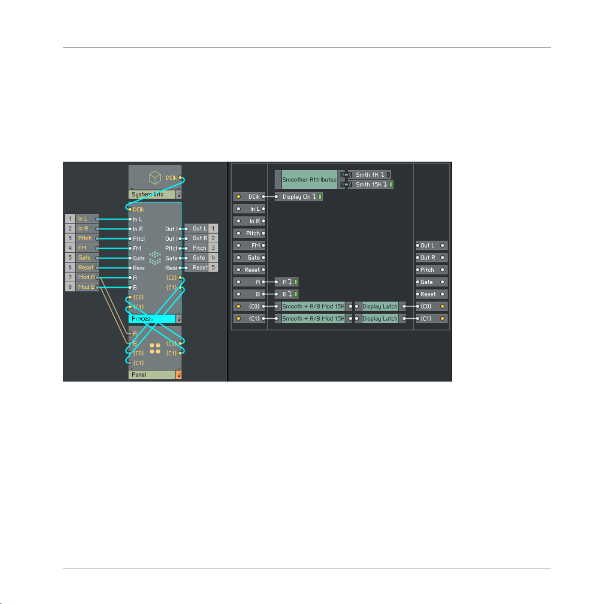
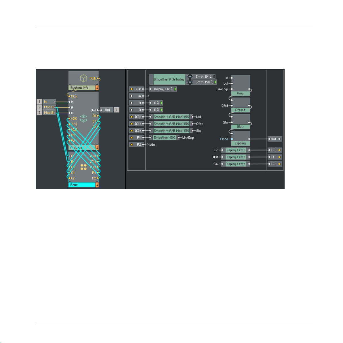
A completed Block
The left image shows the connections between the System Info Macro, Panel Macro, and the
Process Core Cell. The right image shows the inside of the Process Core Cell.
The packaged signals from the panel elements are routed into the Process Core Cell, where
they are unpacked, smoothed, and summed with any modulation received via the A and B distribution buses inside of the Smooth + A/B Mod Macros. The summed signals are then routed
to wherever they are needed within the Core Cell. They are also routed to Display Latch Macros, where they are latched at display rate by the clock received from the System Info Macro
via the Display Clk distribution bus. Finally, the signals are returned to the Panel Macro, where
they are used to display modulation.
REAKTOR Blocks - Framework Manual - 19
Page 20

2 Connections and Signals
A Blocks Patch
Connections and Signals
The most important aspect of the Blocks framework is the universal connectivity between each
Block. A user should be able to connect any output to any input and achieve predictable results, regardless of what modules they are connecting together.
In order to achieve this, all Blocks have been designed to interpret signals within a particular
range, in a particular way. It is important that any additional Blocks are built to the same criteria to ensure compatibility with already existing Blocks.
REAKTOR Blocks - Framework Manual - 20
Page 21

Connections and Signals
Audio Rate Connections
2.1 Audio Rate Connections
Ensuring that all connections between Blocks are audio rate signals serves 2 main purposes.
Primarily, using audio rate signals results in total interconnectivity across the entire framework,
meaning that the user is always able to make any connection they wish. Furthermore, using
audio rate signals ensures that any modulation within a patch is as smooth as possible and
very rapid modulations can be achieved with no detriment to audio quality.
LFO signal at control rate
LFO signal at audio rate
The first image shows the signal from an LFO at control rate. The second image shows the
same signal at audio rate. The higher clocking frequency results in a much smoother waveform.
All Blocks have been designed to function at a standard sample rate of 44.1kHz. Higher sample rates are also supported, but it is inadvisable to use a sample rate lower than 44.1kHz, as
this would have an adverse affect on audio quality.
REAKTOR Blocks - Framework Manual - 21
Page 22

Connections and Signals
2.2 Value Range
Just as all connections between Blocks should be audio rate signals, the value range of those
signals should always remain within a range of [-1, 1]. Again, this serves to ensure compatibility across the entire framework.
There remains still the possibility to exceed that range, either by mixing multiple signals together, or by simply applying excessive amounts of gain to a signal. Never the less, the [-1, 1]
range should be considered the standard operating range at all inputs and outputs.
Signal polarity or bias is less of a concern, and it is perfectly acceptable for signals between
Blocks to be offset or entirely unipolar. It is however inadvisable to connect a biased signal directly to the main output, as this could potentially cause damage to monitoring equipment in
the case where the audio interface used does not have an AC coupled output.
Value Range
REAKTOR Blocks - Framework Manual - 22
Page 23

Connections and Signals
2.3 Pitch Scaling
As all connections between Blocks are audio rate signals within the [-1, 1] range, on occasion
some scaling may be required to convert the signals patched between modules into standard
MIDI note values. To this end, Blocks adopts a scaling system similar to the volts per octave
scheme as found in Eurorack format modular systems.
In the Blocks framework, signals connected to a Pitch input are scaled up by a factor of 120,
so that a value of 0 results in a MIDI note of 0, a value of 0.5 results in a MIDI note of 60,
and a value of 1 results in a MIDI note of 120.
Pitch input scaling
Likewise, MIDI notes received from a host software or MIDI device are scaled down by the
same amount, so that they can be freely patched throughout the Framework.
Pitch Scaling
MIDI note scaling
This scaling scheme means that an increase of 0.1 in a signal connected to a Pitch input will
result in a 1 octave increase in pitch, and an increase of 0.00833333 results in a 1 semitone
increase in pitch.
REAKTOR Blocks - Framework Manual - 23
Page 24

Connections and Signals
2.4 Gate Signals
Various types of Blocks will have a Gate or Reset input, and while the result may be different
depending on the type of Block, a gate signal is always detected in the same way. Once again,
this is to ensure total interconnectivity across the entire framework.
Gate signal detection
The Gate input of any Block will be looking for a positive zero crossing in the signal connected
to it. This is the point at which a signal increases from a value of zero or less, to a value greater than zero. When this positive zero crossing occurs, it is considered a ‘Gate on’ event, and
when the signal returns to a value of zero or less, it is considered a ‘Gate off’ event.
Gate Signals
Gate detection for a sine wave
The actual result of the gate on and off messages will differ, depending on the type of module.
In a sequencer, the gate on event will cause the sequencer to advance 1 step. In an envelope
generator, the gate on event will trigger the envelope, while the gate off event will allow it to
continue into the release stage.
Whatever the type of module, detecting gate events in this way allows for any number of different sources to be used as a gate signal.
REAKTOR Blocks - Framework Manual - 24
Page 25

Connections and Signals
Gate Signals and Velocity
2.5 Gate Signals and Velocity
Blocks such as envelope generators can also be made to respond to gate velocity, rather than
just simple gate on/off messages. Velocity is determined in a manner similar to a typical gate
signal.
Velocity detection
Once again, the Gate input will be looking for a positive zero crossing in the signal connected
to it. When the positive zero crossing occurs it is again considered a ‘Gate on’ event, however
the amount by which the signal has exceeded zero is used to determine the velocity value.
Once the signal has returned to a value of 0 or less, it is considered a ‘Gate off’ message.
When using a triangle wave as a gate signal for a velocity sensitive Block, the resulting gate
signal has a very low velocity since the value at the initial positive zero crossing is very small:
Velocity detection for a triangle wave
When using a saw wave as a gate signal for a velocity sensitive Block, the value at the initial
positive zero crossing is very large, which results in a gate signal with a very high velocity:
REAKTOR Blocks - Framework Manual - 25
Page 26

Velocity detection for a saw wave
Connections and Signals
Gate Signals and Velocity
REAKTOR Blocks - Framework Manual - 26
Page 27

3 Panel Widgets
Panel Widgets
Blocks Panel template
The template contains a wide selection of panel widgets, which can be used when building a
new Block. Widgets are provided in both Light on Dark and Dark on Light color schemes so
that they are always visible, whatever the chosen panel color might be.
REAKTOR Blocks - Framework Manual - 27
Page 28

Panel Widgets
All widgets can be easily customized, making tasks such as renaming parameters, setting knob
color, or changing the type of value readout quick and simple to achieve.
REAKTOR Blocks - Framework Manual - 28
Page 29

3.1 Color Schemes
Panel Widgets
Color Schemes
Two color schemes
The template contains a wide selection of panel widgets, which can be used when building a
new Block. Widgets are provided in both Light on Dark and Dark on Light color schemes so
that they are always visible, whatever the chosen panel color might be.
All widgets can be easily customized, making tasks such as renaming parameters, setting knob
color, or changing the type of value readout quick and simple to achieve.
REAKTOR Blocks - Framework Manual - 29
Page 30

Panel Widgets
3.1.1 Additional Knob Colors
Knobs in different colors
The template contains a wide selection of panel widgets, which can be used when building a
new Block. Widgets are provided in both Light on Dark and Dark on Light color schemes so
that they are always visible, whatever the chosen panel color might be.
All widgets can be easily customized, making tasks such as renaming parameters, setting knob
color, or changing the type of value readout quick and simple to achieve.
Color Schemes
REAKTOR Blocks - Framework Manual - 30
Page 31

3.2 Template Blocks
Panel Widgets
Template Blocks
Empty Blocks
Also included with the template is a selection of empty Blocks. These have already been set to
the correct dimensions to ensure they fit with existing Blocks. In addition, each empty Block
also contains the most essential Macros needed to begin building. The most commonly used
sizes have been provided, however it is a very simple process to set different sizes too. More
information on this can be found in section ↑1.2.1, Size Macro.
REAKTOR Blocks - Framework Manual - 31
Page 32

Panel Widgets
Process Macros
3.3 Process Macros
Process Macros
As well as the various panel widgets, the template also includes a wide selection of Macros for
use inside of a Block’s Process Core Cell. Primarily, these are the Macros required to utilize
the various widgets most effectively, or to interpret any signals connected to a Block such as
Pitch and Gate.
REAKTOR Blocks - Framework Manual - 32
Page 33

Panel Widgets
3.4 Knobs
3.4.1 Basic Knobs
Basic knobs
Available in three different sizes, the signal provided by the basic knob requires no additional
Macros after entering a Core Cell, except for smoothing when necessary.
Knobs
Output value range is [0, 1].
Label & Value Macro
Inside of the basic knob Macro is another Macro named Label & Value. This contains the text
modules used for displaying parameter name and value, as well as additional modules used to
determine which is visible at any particular time. Here the parameter name can be changed,
and value display adjusted as needed. Alternatively, more complex Label & Value Macros have
been provided for more specific cases, and can be used as a replacement if desired.
REAKTOR Blocks - Framework Manual - 33
Page 34

Panel Widgets
3.4.2 Basic Knobs (Bipolar)
Bipolar knobs
Similar to the basic knob, with the only difference being that the bipolar knob includes a center point indicator, and a bipolar value display.
Output value range is [0, 1].
Customization of both label and value can be carried out in the exact same way as described
for the basic knob.
Knobs
3.4.3 Modulation Knobs
Modulation knobs
REAKTOR Blocks - Framework Manual - 34
Page 35

Panel Widgets
More complex than the basic knob, the modulation knob Macro also includes the two sliders
used for defining modulation depth, and an additional modulation ring which displays any
modulation currently assigned to that parameter. Connecting the output from the A/B Buttons
Macro to the A/B Buttons input gives control over when the modulation sliders are visible. Signals connected to the Mod Return input will be displayed by the modulation ring.
The signal sent from the modulation knob output is a multiplexed signal comprised of the
main knob as well as the two modulation depth sliders. Therefore, a Smooth + A/B Mod Macro
should be used inside of the Process Core Cell in order to correctly demultiplex the signal,
smooth, and apply modulation before routing the signal to its final destination.
Modulation knob parameter names and values can be customized inside of the Label & Value
Macro, or alternatively, the Label & Value Macro can be replaced with one of the others included with the template.
3.4.4 Modulation Knobs (Bipolar)
Knobs
Bipolar modulation knobs
Similar to the modulation knob, with the only difference being that the bipolar knob includes a
center point indicator, and a bipolar value display. Just like the modulation knob, the bipolar
modulation knob also outputs a multiplexed signal, and so a Smooth + A/B Mod Macro should
be used inside of the Process Core Cell.
Customization of both label and value can be carried out in the exact same way as described
for the modulation knob.
REAKTOR Blocks - Framework Manual - 35
Page 36

Panel Widgets
3.4.5 OSC Tuning
OSC Tuning Macro
The OSC tuning Macro contains all the parameters commonly used when building oscillator
Blocks. A switch to enable/disable key tracking, a modulatable coarse tuning control which
switches between note value or frequency value depending on whether key tracking is enabled,
and a fine tuning control.
The coarse tuning control output is a multiplexed signal as described in the Modulation Knob
section, the fine tuning control is a simple knob with an output value range of [0, 1], and the
key tracking switch is a simple on/off switch with an output value range of [0 .. 1].
Knobs
Since each parameter has its own output, these signals can all be treated separately if desired.
For ease of use however, the template also includes a Core Cell Macro specifically designed for
the purpose of receiving these values, along with any pitch signals patched into the Block.
OSC Tuning Macro in use
The left image shows the three signals sent from the OSC tuning Macro, as well as the modulation return needed to display modulation of the ‘Coarse’ parameter. The right image shows the
same three signals arriving in the Process Core Cell. Note that since the coarse parameter {C1}
is multiplexed, a Smooth + A/B Mod Macro is used to demultiplex and apply any modulation
REAKTOR Blocks - Framework Manual - 36
Page 37

Panel Widgets
before connection to the OSC Tuning Core Macro. In addition, the output from the Smooth +
A/B Mod Macro is also connected to a ‘Display latch’ Macro before being routed back to the
Panel Macro so that modulation can be displayed.
3.4.6 Multiplex Knobs
Multiplex knobs
The multiplex knobs Macro contains eight separate basic knobs, which are multiplexed into a
single output. While there are eight by default, additional knobs can be added, or removed as
required. Since the output from all knobs is multiplexed into a single connection, demultiplexing is required inside of the Process Core Cell. The template includes two suitable demultiplexing Core Macros. One will simply unpack the multiplexed input into its constituent signals,
while the other writes the signals into an array.
Knobs
The output value range of each knob is [0, 1], and the label and value displays of each knob
can be customized as needed.
REAKTOR Blocks - Framework Manual - 37
Page 38

Panel Widgets
Customizing Knobs
3.5 Customizing Knobs
3.5.1 Color
Changing the knob color
The multiplex knobs Macro contains eight separate basic knobs, which are multiplexed into a
single output. While there are eight by default, additional knobs can be added, or removed as
required. Since the output from all knobs is multiplexed into a single connection, demultiplexing is required inside of the Process Core Cell. The template includes two suitable demultiplexing Core Macros. One will simply unpack the multiplexed input into its constituent signals,
while the other writes the signals into an array.
The output value range of each knob is [0, 1], and the label and value displays of each knob
can be customised as needed.
REAKTOR Blocks - Framework Manual - 38
Page 39

Panel Widgets
Customizing Knobs
3.5.2 Labels
Changing the knob label
Changing the label displayed underneath a knob is a quick process. The text module used to
display the parameter name can always be found in the Label & Value Macro found in every
knob module.
Simply locate the Label Macro, and edit the text module inside.
3.5.3 Values
Changing the knob values
REAKTOR Blocks - Framework Manual - 39
Page 40

Panel Widgets
Customizing Knobs
By default, all panel widgets come with a basic [0, 100] value display, or [-100, 100] if the
parameter is bipolar. The value display is found in the same location as the label, and can be
edited in much the same way.
In cases where more complex value displays are required, such as frequency or envelope times,
the generic Label & Value Macro can be replaced in its entirety with one of the more specialized Macros included in the ‘Value Displays’ Macro.
REAKTOR Blocks - Framework Manual - 40
Page 41

Panel Widgets
3.6 Buttons
3.6.1 Basic Button
Basic Button
Available in three different sizes, the signal sent by the basic button requires no additional
Macros after entering a Core Cell, except for smoothing if necessary.
Output value range is [0 .. 1].
Buttons
By default, the basic button text display will switch between “OFF” and “ON”. This can be
changed by editing the multitext module found inside of the Macro.
3.6.2 Basic Color Button
Basic color button
Essentially the same as the basic button, with the only difference being that the color button
switches between grey when off, and a selectable color when on, allowing for easy panel customization. Integer values between 0 and 15 at the Color input select different colors.
REAKTOR Blocks - Framework Manual - 41
Page 42

Panel Widgets
Output value range is [0 .. 1].
By default, the basic color button will switch between “OFF” and “ON”. This can be changed
by editing the multitext module found inside of the Macro.
3.6.3 Multistate Button
Multistate button
While the basic button only provides two possible values, 0 and 1, the multistate button can
provide a definable number of values. The output value begins at 0, and increases by 1 every
time the button is clicked. Once the maximum value is reached, the output value returns to 0.
By default, the multistate button has 4 states and an output range of [0 .. 3]. The number of
states can be changed by editing the constant value found inside of the Macro. Similarly the
text displayed for each state can also be modified, by editing the multitext module inside of
the Macro.
Buttons
3.6.4 Multistate Color Button
Multistate color button
REAKTOR Blocks - Framework Manual - 42
Page 43

Panel Widgets
The multistate color button offers the same functionality as the multistate button, with the only difference being that the color button switches between grey when 0, and a selectable color
for all other values. Integer values between 0 and 15 at the Color input will select different
colors.
By default, the multistate color button has 4 states and an output range of [0 .. 3]. The number of states can be changed by editing the constant value found inside of the Macro. Similarly
the text displayed for each state can also be modified, by editing the multitext module inside
of the Macro.
3.6.5 Radio Buttons
Radio buttons
Similar to the multistate button Macro, the radio buttons Macro also provides a definable number of values. The difference being that rather than a using a single button, the different states
are selected via several on screen buttons.
Buttons
By default, the radio buttons Macro has six states with an output range of [0 .. 5] however,
states can be added or removed as required. In addition, the text display for each button can
also be modified by editing the text modules inside of the Macro.
3.6.6 Radio Color Buttons
Radio color buttons
REAKTOR Blocks - Framework Manual - 43
Page 44

Panel Widgets
With the same functionality as the radio buttons, the Radio Color Buttons switch between grey
when off, and a selectable color when on, allowing for easy panel customization. Integer values
between 0 and 15 at the Color input select different colors.
By default, the radio color buttons Macro has six states with an output range of [0 .. 5] however, states can be added or removed as required. In addition, the text display for each button
can also be modified by editing the text modules inside of the Macro.
3.6.7 Multiplex Buttons
Multiplex buttons
The multiplex buttons Macro contains eight separate basic buttons, which are multiplexed into
a single output. While there are eight by default, additional buttons can be added or removed
as required. Since the output from all buttons is multiplexed into a single connection, demultiplexing is required inside of the Process Core Cell. The template includes two suitable demultiplexing Core Macros. One will simply unpack the multiplexed input into its constituent signals,
while the other writes the signals into an array.
Buttons
The output value range of each button is [0 .. 1], and the text display of each button can be
customized as needed, by editing the text modules inside of the Macro.
3.6.8 Multiplex Color Buttons
Multiplex color buttons
Functionally the same as the Multiplex Buttons, but with the additional option to quickly select a different color for the on states. Integer values between 0 and 15 at the Color input select between the sixteen available colors.
REAKTOR Blocks - Framework Manual - 44
Page 45

Panel Widgets
The output value range of each button is [0 .. 1], and the text display of each button can be
customized as needed, by editing the text modules inside of the Macro.
3.6.9 A/B Buttons
A/B buttons
The A/B Buttons Macro does not connect to the Process Core Cell. Instead, its output should
be connected to the A/B Buttons input found on any modulatable panel widget, such as the
Modulation Knob. Clicking the A/B Buttons will then determine when that panel widget’s modulation sliders are visible.
The A/B Buttons Macro also has two inputs, A and B. These inputs should be connected to the
Block’s A and B modulation bus inputs in order to display the signal strength and polarity of
any incoming modulation.
Buttons
The A/B Buttons Macro output range is [0 .. 2]. When neither button is active, output value is
0 and no modulation faders are visible. When button A is active, output value is 1 and modulation bus A sliders are visible. When button B is active, output value is 2 and modulation bus B
sliders are visible.
REAKTOR Blocks - Framework Manual - 45
Page 46

Panel Widgets
3.7 Meters
3.7.1 Meter Mono
Meter Mono
The Meter Mono Macro is a simple level meter, useful for displaying mono signal levels in dB.
It is comprised of several different elements. As well as the main level meter, there is also a
peak level meter, and numeric readout which will change color when the input signal exceeds
0dB.
Meters
Integer values between 0 and 15 at the Color input will set the meter to one of the sixteen
available color options.
3.7.2 Meter Stereo
Meter Stereo
REAKTOR Blocks - Framework Manual - 46
Page 47

Panel Widgets
Stereo version of the Meter widget. As before, meter color can be selected at the color input.
An integer value between 0 and 15 will select one of the 16 available color options.
Meters
REAKTOR Blocks - Framework Manual - 47
Page 48

Process Macros
4 Process Macros
Process Macros
In addition to the wide selection of Panel Widgets, the template also includes several Macros
for use inside of a Block’s Process Core Cell. Primarily, these Core Macros are designed to work
in conjunction with the various panel elements available, or to interpret incoming signals such
as pitch, gate, and modulation.
REAKTOR Blocks - Framework Manual - 48
Page 49

Process Macros
4.1 Inputs
Display Clk
Display Clk
The DClk input and the attached Display Clk distributor receive a clocking signal sent from the
System Info Macro, and distribute it throughout the Process Core Cell. This clocking signal is
used to clock signals being returned to the Block’s panel, which are to be used for displaying
modulation. Modulation signals are audio rate, and it would be inefficient to connect them directly to any form of display. Clocking these signals at display rate results in a noticeable increase in efficiency.
Random Seed
Random Seed
Inputs
The RS input and the attached Random Seed distributor receive a value sent from the System
Info Macro, and distribute it throughout the Process Core Cell. A new random value is sent every time the patch is re-initialized. This value can be used as a seed wherever a degree of randomization is required, such as noise generators or random sequences.
Pitch / Pitch Mult
Pitch / Pitch Mult
Signals between Blocks should always remain within the [-1, +1] range. Typically a pitch signal will have a range of [0, 1], but on occasion it may be preferable to scale this up to typical
MIDI note values. The Pitch input will receive any signals connected to the Block’s Pitch input, while the Pitch Mult Macro scales this signal up to MIDI note values.
REAKTOR Blocks - Framework Manual - 49
Page 50

Process Macros
Gate / Int Gate / Vel Gate
Gate / Int Gate / Vel Gate
Signals connected to the Block’s Gate input are passed on to the Gate input of the Process
Core Cell. The Int Gate and Vel Gate Macros will convert the incoming audio rate signal into a
usable gate.
They both function in much the same way, by looking for a positive zero crossing in the input
signal. When the signal rises above 0 it is considered a gate on, and when the signal returns to
0 or less it is considered a gate off.
The Int Gate Macro effectively acts as an audio to logic converter, only outputting either 0 or
1. This can be used for any gated functions where velocity information is not required, such as
restarting an LFO or advancing a sequencer.
The Vel Gate also sends velocity information. Velocity is determined by the value of the input
signal, immediately after a positive zero crossing. This can be used for any gated function
where velocity information is required, such as an envelope generator.
Inputs
Reset
Reset
The Reset input and Macro function in much the same way as the Gate input. Signals connected to the Block’s reset input are passed on the Reset input of the Process Core Cell which is in
turn connected to the Reset Core Macro.
Like the Gate Macro, the Reset Macro is also looking for positive zero crossings in the input
signal. However, every time a positive zero crossing occurs the Reset Macro will output a value
of 0. This can be used to reset any counters within the Block, as might be found in a sequencer or clock divider.
REAKTOR Blocks - Framework Manual - 50
Page 51

Process Macros
A and B
A and B
The A and B inputs are where signals connected to the Mod A and Mod B inputs of the Block
are received inside of the Process Core Cell. Both inputs are connected directly to distributors,
so that incoming modulation can be picked up wherever needed within the Process Core Cell.
Macros such as the Smooth + A/B Mod are already designed to pick up signals distributed by
the A and B buses, so that no additional patching is required.
Inputs
REAKTOR Blocks - Framework Manual - 51
Page 52

Process Macros
Smoothing and Modulation
4.2 Smoothing and Modulation
Smoother Attributes
Smoother Attributes
The Smoother AttributesMacro is responsible for creating the various signals needed for the
smoothing of parameter inputs i.e. smoothing time and rate. These attributes are distributed
throughout the Process Core Cell by the two distributors. Two different smoothing rates are provided, 1 kHz and 15 kHz.
Macros such as the Smooth + A/B Mod are already designed to pick up signals distributed by
the Smoother AttributesMacro, so that no additional patching is required.
Smoother
Smoother
The smoother Macro serves to smooth the event rate signals arriving from the Panel Macro, in
order to avoid discontinuity in signals, audible ‘pops’ and other such undesirable artifacts. It
can be used after to smooth the signals received from knobs, buttons or any other non multiplexed input signal.
The smoother is available at either 1 kHz or 15kHz rate. Both Macros are already designed to
pick up the necessary signals, as distributed by the Smoother AttributesMacro.
For multiplexed signals, such as those sent by a Modulation Knob panel widget, the Smooth +
A/B Mod Macro should be used instead.
REAKTOR Blocks - Framework Manual - 52
Page 53

Process Macros
Smoothing and Modulation
Smooth + A/B Mod
Smooth + A/B Mod
As the signal sent from the Modulation knobs a multiplexed signal, comprised of the main
knob as well as the two modulation depth sliders, a Smooth + A/B Mod Macro should be used
inside of the Process Core Cell in order to correctly demultiplex the signal, smooth, and apply
modulation.
The Smooth + A/B Mod is available at either 1 kHz or 15kHz rate. Both versions are already
designed to pick up the signals distributed from the A and B modulation buses, as well as the
appropriate signals distributed by the Smoother AttributesMacro.
A/B Mod Q
A/B Mod Q
The A/B Mod Q Macro can also be used for demultiplexing signals arriving from Modulation
Knob panel elements, and applying modulation. The difference between this Macro and the
Smooth + A/B Mod Macro, is that the A/B Mod Q will quantize the resulting signal into a deter-
mined number of steps. This can be particularly useful when creating modulatable parameters
with only a small number of possible values, such as the length parameter of a sequencer.
The X input sets the number of steps. The *X output sends integer values ranging from 0 to X,
while the 1/X output scales the final value, so that it remains within the [0, 1] range. Typically
the *X output would be routed to wherever it is needed within the Core Cell, while the 1/X output should be routed back to the panel element to display modulation.
Uni 2 Bi
Uni 2 Bi
REAKTOR Blocks - Framework Manual - 53
Page 54

Process Macros
Smoothing and Modulation
All signals arriving in the Process Core Cell from the various panel widgets will be unipolar,
with a linear value range of [0, 1]. In some instances it may be preferable to convert these signals to a bipolar value range. These two simple Macros can be used to achieve just that.
A unipolar [0, 1] signal arriving at the input will be converted into a bipolar [-1, 1] signal at
the output. The Uni 2 Bi (lin) module output will have a linear control shape, while the Uni 2
Bi (Para) module output will have a parabolic (x^2) control shape.
Both modules should be placed after any modulation or smoothing Macros, such as the
Smooth + A/B Mod.
OSC Tuning
OSC Tuning
The OSC Tuning Macro is designed specifically to work in conjunction with the OSC Tuning
panel widget.
OSC Tuning in use
In the case of the Coarse parameter, the signal should be first connected to a Smooth + A/B
Mod Macro, in order to apply smoothing and modulation. The Fine parameter should be connected to a Smoother Macro, before being connected to the OSC Tuning Core Cell.
The KTrack parameter requires no additional processing, and the input signal can be connected directly to the Core Macro.
The Pitch input accepts values in the range of [0 ,1] meaning signal received from other
Blocks can be connected directly, without the need for any scaling.
The OSC Tuning Macro has two outputs. The Pitch output provides MIDI note values, while the
Freq output provides frequency values in Hertz.
REAKTOR Blocks - Framework Manual - 54
Page 55

Process Macros
Select and Distribute
4.3 Select and Distribute
Clk Select
Clk Select
The Clk Select Macro can be used to select between different input signals. By default it has
four inputs, but more can be added or removed if needed.
The input signals are connected to latches within the Macro. A Clock signal is then sent to the
latch of the desired input, allowing it to pass to the output. The sample rate clock (SR.C) is
connected by default, although a different clock can be connected to the Clk input if needed.
The Sel input accepts integer values for selecting which input is to be clocked.
Clk Distro
Clk Distro
The Clk Distro Macro can be used to distribute a clock signal between several different outputs. By default it has four outputs, but further outputs can be added or removed if needed.
In particularly complex structures, it is often preferential to distribute clocking signals only to
the sections of a structure which are currently in use. By distributing the clock exclusively to
where it is needed at that particular moment, structures can be made to be considerably more
efficient.
By default, the Clk Distro Macro will distribute the sample rate clock (SR.C) signal. A different
clock can be used by connecting it to the Clk input.
REAKTOR Blocks - Framework Manual - 55
Page 56

The Sel input accepts integer values, selecting which output to send the clock signal from.
Process Macros
Select and Distribute
Clk Distro in use
A typical application of the Clk Distro Macro. In this example, the clock signal is distributed
between the various different waveforms produced by an LFO. Only the shape currently selected receives a clock, while the remaining shapes are inactive, resulting in a significant increase
in efficiency.
REAKTOR Blocks - Framework Manual - 56
Page 57

Process Macros
4.4 Counting
Clk Count
Clk Count
The Clk Count Macro is a simple counter, ideal for counting gate events or button presses.
Clk Count in use
A typical application of the Clk Count Macro. Every positive zero crossing in the signal arriving
at the Gate input results in a value of 1 being sent from the Int Gate Macro output. This causes the value at the Clk Count output to increase by 1.
A positive zero crossing in the signal arriving at the Reset input results in a value of 0 being
sent from the Reset Macro output. This causes the Clk Count Macro to reset to zero, and begin
counting again.
Counting
Clk Count / Wrap
Clk Count / Wrap
The Clk count/Wrap Macro is similar to the Clk Count Macro, and both Clk and Rst inputs
function in exactly the same way. The Clk Count/Wrap Macro however also includes a Max input.
While the Clk Count Macro will advance indefinitely until it receives a reset signal, the Clk
Count/Wrap Macro will only count as far as the value provided at the Max input, after which it
will return to 0 and begin counting again.
REAKTOR Blocks - Framework Manual - 57
Page 58

Process Macros
4.5 Demultiplex
Button DMux
Button DMux
The Button DMux is a simple demultiplexer, designed to be used in conjunction with the Mul-
tiplex Buttons panel widget. The signal arriving from the panel widget should be connected directly to the Button DMux input. The values sent by the eight buttons will then available at the
eight outputs.
If additional buttons have been added to the Multiplex Buttons panel widget, then the Button
DMux Macro should also be suitably modified.
Demultiplex
Knob DMux
Knob DMux
Similar to the Button DMux Macro, the Knob DMux Macro is also a simple demultiplexer, however it is designed for use in conjunction with the Multiplex Knobs panel widget. The signal
arriving from the panel widget should be connected directly to the Knob DMux input. The values sent from the eight knobs will then be available at the eight outputs.
REAKTOR Blocks - Framework Manual - 58
Page 59

Process Macros
If additional buttons have been added to the Multiplex Knobs panel widget, then the Knob
DMux Macro should also be suitably modified.
Button DMux/Seq
Button DMux/Seq
The Button DMux/Seq Macro is another type of demultiplexer, designed to be used in conjunction with the Multiplex Buttons panel widget. How it differs from the basic Button DMux Macro
is that rather than simply routing each constituent button to a dedicated output, the state of
each button is written to an array within the Macro.
The Idx input accepts integer values, and specifies which index of the array is to be sent to the
Macro’s output. The Button DMux/Seq is especially suitable for making sequencers, by connecting the sequencer position to the Idx input.
If additional buttons have been added to the Multiplex Buttons panel widget, then the Button
DMux/Seq Macro should also be suitably modified.
Knob DMux/Seq
Demultiplex
Knob DMux/Seq
Similar in concept to the Button DMux/Seq Macro, the Knob DMux/SeqMacro is also a demultiplexer and array Macro, but designed for use with a multiplexed float signal, specifically that
provided by the Multiplex Knobs Macro.
As on the Button DMux/Seq Macro, the Idx input accepts integer values to determine which
index of the array is sent to the Macro’s output. Again, this is particularly useful when making
sequencers.
If additional buttons have been added to the Multiplex Knobs panel widget, then the Knob
DMux/Seq’Macro should also be suitably modified.
REAKTOR Blocks - Framework Manual - 59
Page 60

Process Macros
Knob DMux/Seq in use
Using the Knob DMux/Seq’Macro as part of a basic sequencer. The output from the Multiplex
Knobs panel widget is connected to the input of the Knob DMux/Seq’Macro. A positive zero
crossing in the signal arriving at the Gate input is converted to a value of 1 by the Int Gate
Macro. This will increase the output value of the Clk Count/Wrap Macro by 1, which in turn
selects the next index value from the Knob DMux/Seq’Macro.
Demultiplex
REAKTOR Blocks - Framework Manual - 60
Page 61

Process Macros
4.6 Outputs
Pitch Div
Pitch Div
Essentially the opposite of the Pitch Mult Macro. The function of the Pitch Div Macro is to
scale pitch signals back to the [0, 1] range, in the case where they had been previously scaled
up to standard MIDI note values.
Display Latch
Display Latch
The Display Latch Macro should be used before routing modulation signals back to the Panel
Macro for display. The Display Latch is designed to pick up the display clock signal distributed
within the Core Cell by the Display Clk distribution bus. Signals connected to the Display Latch
are then clocked at display rate, resulting in increased efficiency.
Outputs
Display iLatch
Display iLatch
The Display iLatch Macro is essentially the same as the Display Latch Macro, with the only difference being that while the Display Latch is designed for use with float signals, the Display
iLatch Macro should be used with integer signals.
REAKTOR Blocks - Framework Manual - 61
 Loading...