

Page 1

FM8
Operation Manual
Page 2

The information in this document is subject to change without notice and does
not represent a commitment on the part of NATIVE INSTRUMENTS GmbH. The
software described by this document is subject to a License Agreement and may not
be copied to other media. No part of this publication may be copied, reproduced or
otherwise transmitted or recorded, for any purpose, without prior written permission
by NATIVE INSTRUMENTS GmbH, hereinafter referred to as NATIVE INSTRUMENTS.
All product and company names are trademarks of their respective owners.
Furthermore, the fact that you are reading this text means you are the owner of
legal version rather than an illegal, pirated copy. It is only through the loyalty and
honesty of people like yourself that NATIVE INSTRUMENTS GmbH can continue
to develop and create innovative audio software. On behalf of the entire company,
thank you very much.
Users Guide written by Thomas Loop
Special thanks to the Beta Test Team, who were invaluable not just in tracking down
bugs, but in making this a better product.
© NATIVE INSTRUMENTS GmbH, 2006. All rights reserved.
Germany USA
NATIVE INSTRUMENTS GmbH NATIVE INSTRUMENTS North America, Inc.
Schlesische Str. 28-30 5631 A Hollywood Boulevard
D-10997 Berlin Los Angeles, CA 90028
Germany USA
info@native-instruments.de info@native-instruments.com
www.native-instruments.de www.native-instruments.com
Page 3

Table Of Contents
1. Welcome to FM8 ............................................................................ 6
2. Installation and Setup .................................................................... 7
3. Overview and Tutorial ..................................................................... 7
3.1. New in This Version .................................................................. 7
3.1.1. New Features ................................................................. 7
3.2. Basic Concepts ........................................................................ 9
3.2.1. Frequency Modulation ..................................................... 9
3.2.2. Modulating Parameters ..................................................10
3.2.3. Morphing Sounds ..........................................................11
3.2.4. Arpeggiate ....................................................................11
3.3. Outline of the Interface ............................................................12
3.3.1. Global Sections: Application Control Bar, Navigator and
Keyboard ................................................................................12
3.3.2. Browser & Attributes Page ..............................................13
3.3.3. Master Window .............................................................13
3.3.4. Effects Window .............................................................14
3.3.5. Arpeggiator Window .......................................................14
3.3.6. Easy/Morph Page...........................................................15
3.3.7. Expert Windows .............................................................15
3.4. Quickstarts ............................................................................ 20
3.4.1. Loading and Using Sounds..............................................21
3.4.2. Morphing and Easy Editing ............................................ 22
3.4.3. Using the Arpeggiator and Modifying Attributes.................24
3.4.1. Create your First Sound from Scratch ...............................27
4. Reference ................................................................................... 33
4.1. What is Frequency Modulation? ................................................ 33
4.1.1. The Basics ................................................................... 33
4.1.2. Meet the Algorithm ....................................................... 34
4.1.3. Feedback ..................................................................... 35
4.1.4. The Envelope Generator ................................................. 35
4.2. Interaction with the GUI .......................................................... 36
4.2.1. Mac and Windows Conventions ...................................... 36
4.2.2. Buttons and Switches .................................................. 36
4.2.3. Faders and Knobs......................................................... 36
4.2.4. Numeric Values .............................................................37
4.2.5. Popup Menus ................................................................37
4.2.6. FM Matrix .................................................................... 38
4.2.7. Graphical Interfaces ..................................................... 39
FM8 – 3
Page 4

4 – FM8
4.2.8. Envelopes .................................................................... 40
4.2.9. Pages and Tabs ............................................................ 40
4.3. Standalone menus .................................................................. 40
4.3.1. File Menu .................................................................... 40
4.3.2. Help Menu ...................................................................41
4.4. Application Control Bar ............................................................41
4.4.1. Options ........................................................................41
4.4.2. Menu Functions and Status Displays .............................. 45
4.5. Navigator ................................................................................47
4.6. Keyboard ............................................................................... 48
4.7. Master Window ....................................................................... 48
4.7.1. Level Controls ............................................................... 48
4.7.2. Voices and Polyphony .....................................................49
4.7.3. Pitch and Portamento .................................................... 50
4.7.4. Arpeggiator and Quality ..................................................51
4.7.5. MIDI Controls ................................................................51
4.8. Effects Window ...................................................................... 52
4.8.1. Overdrive ..................................................................... 53
4.8.2. Tube Amp .................................................................... 53
4.8.3. Cabinet ....................................................................... 53
4.8.4. Shelving EQ ................................................................. 55
4.8.5. Peak EQ ...................................................................... 55
4.8.6. Talk Wah ..................................................................... 56
4.8.7. Phaser ........................................................................ 56
4.8.8. Flanger ........................................................................57
4.8.9. Tremolo ....................................................................... 58
4.8.10. Reverb ....................................................................... 58
4.8.11. PsycheDelay ............................................................... 59
4.8.12. Chorus / Delay ............................................................ 60
4.9. Arpeggiator Window .................................................................61
4.9.1. Arpeggiator Controls ...................................................... 62
4.9.2. Pattern Editor .............................................................. 65
4.10. Easy / Morph Window ............................................................ 66
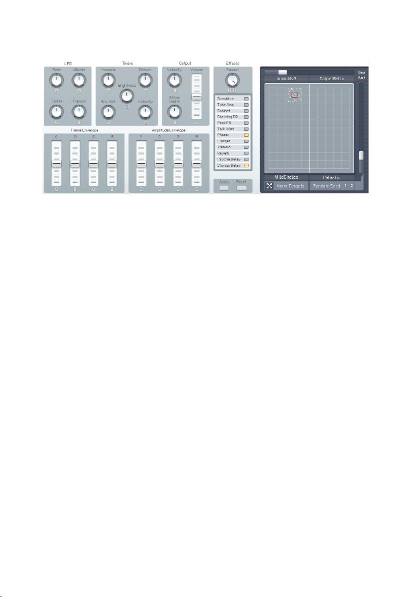
4.10.1. Timbre Controls .......................................................... 67
4.10.2. Output Controls .......................................................... 68
4.10.3. LFO and Amplitude Envelopes ...................................... 68
4.10.4. Apply and Reset ..........................................................69
4.10.5. Effect Controls ............................................................70
4.10.6. Morph Controls ............................................................70
Page 5

4.11. Expert Controls ......................................................................72
4.11.1. FM Matrix ...................................................................72
4.11.2. Operator A-E Pages ......................................................74
4.11.3. Operator X Window ...................................................... 80
4.11.4. Operator Z Window ...................................................... 83
4.11.5. Operators Window ....................................................... 86
4.11.6. Envelopes Window ...................................................... 88
4.11.7. Modulations Windows................................................... 89
4.11.8. Key Scaling Window .................................................... 92
4.11.9. Pitch Window ............................................................. 95
4.11.10. Spec Window ............................................................ 99
4.12. Browser and Attributes Window .............................................100
4.12.1. Attribute Concept .......................................................100
4.12.2. Searching and Loading Sounds with the Browser ...........101
4.12.3. Dening Attributes and Saving Sounds .........................106
4.12.4. Loading FM7 Sounds .................................................108
4.12.5. Importing System Exclusive Data .................................109
Appendix A – Attributes Explained ....................................................110
Appendix B – Attributes Reference ...................................................120
Appendix C – Keyboard Shortcuts .....................................................133
Index .............................................................................................134
FM8 – 5
Page 6

1. Welcome to FM8
Congratulations on your purchase of the Native Instruments FM8 software
synthesizer. You’ll be glad you did.
The FM8 is based on FM synthesis, which made its mass market debut in
1983 with the Yamaha DX7. Boasting aftertouch, velocity sensitivity, a new
type of synthesis that was very different from analogue subtractive synthesizers,
a new protocol called “MIDI,” and a shockingly low list price, the DX7 was
an instant hit and went on to become the best-selling synthesizer of its time.
It spawned several offspring, including the famous TX81Z (still one of the
best synths for MIDI guitar) and the TX802, probably the nest hardware
implementation of FM synthesis that Yamaha ever produced.
Native Instruments brought back FM synthesis with the FM7, and it was better
than ever. The new incarnation of this successful synthesizer is the FM8.
Designed as a convenient plug-in, the FM8 has 32-bit resolution for superb
sound quality, an innovative algorithm programming matrix whose exibility
is light years ahead of older FM synthesizers, extensive modulation, a rack of
effects, a lter module/Operator, multiple waveforms and an Arpeggiator.
Although FM synths had a reputation of being difcult to program – and they
were! - the FM8 offers a unique “easy” page that makes it simple to customize
sounds to perfection, without having to learn programming.
All the great features of FM synthesis are included, such as an “analog” control
to add slight amounts of randomness, and a microtuning page for alternate
tunings. But it also has modern essentials, such as envelope and delay sync
to host tempo, 64-voice polyphony, variable resolution for lo- sounds, total
MIDI control, and much more to bring FM synthesis into the 21st century.
The FM8 integrates perfectly into the computer-based virtual studio, whether
Macintosh or Windows. It can serve as a stand-alone module, turning your
computer into a synthesizer. It also works as a sequencer plug-in with various
interfaces.
If you were around for the rst wave of FM synthesis, you’ll be pleasantly
surprised at just how good it can sound with up-to-date technology. If you’re
new to FM synthesis, you’re in for a great time. You can coax sounds out of
the FM8 that range from angelically clean to hellishly nasty...from sweet to
sour...and from traditional to innovative.
6 – FM8
Page 7

2. Installation and Setup
Your FM8 ships with a separate manual – the Setup Guide - providing details
about all things installation and setup. Please follow the Setup Guide’s
instructions before you proceed with the information given in this manual.
3. Overview and Tutorial
3.1. New in This Version
Native Instruments has built upon the years of experience with the FM7 and
came up with a host of new and exciting features for the FM8.
All FM 7 functionality is still available in FM8, and FM8 is 100% backwards
compatible with FM7 sounds.
3.1.1. New Features
Usability
• The “Easy page” is more prominently featured and simplies quick
sound tweaks.
• An Expert Page provides access to all Operator details for advanced
programming tasks.
• The overall functionality of the various Edit Pages has been improved
for a better sound design experience.
• The new, unied NI Sound Browser has beren added, streamlining the
functionality of all NI synthesis products.
Large Amount of Factory Sounds
• The FM8 sports all FM7 factory Sounds, as well as the FM7 Sounds Vol.
1 & Vol. 2 from the NI Sound Line.
• About 200 additional new Sounds come with the FM8, featuring the
new capabilities of the software.
• 12 new rack effects in addition to the FM7 effects.
• All sounds already attributed and ready for KORE.
FM8 – 7
Page 8

Arpeggiator
The FM8 features a uniquely exible, programmable Arpeggiator with a step
sequencer-like matrix of up to 32 steps.
You get:
• Different modes for pattern generation
• Keyboard split features (arpeggios triggered by parts of the keyboard
only)
• Preset Arpeggio templates
Sound Morphing
One of the key new features in FM8 is Sound Morphing. It enables you to
seamlessly morph between 4 arbitrarily chosen timbres.
There is an X-Y-control with each corner corresponding to one complex timbre.
The 4 timbres are easily assigned using drag and drop from the Sound Browser.
A graphic handle in the square is used for setting the interpolation (interpolated
from the corner’s parameter values).
• When running the FM8 as a plug-in in a host that supports automation,
the handle's movement can be automated.
• Only timbre parameters can be morphed. This is essentially the FMMatrix and the Operator settings. Envelopes and modulation settings
are not morphed
• Effects are not morphed, but the Effects amount parameter is
morphed.
High Resolution mode
The High resolution mode improves the general sound quality by reducing
aliasing (in FM modulation, the X-Operator wave shaping, the overdrive effect
or the tube amp effect) and achieves a cleaner and more analogue sound. This
feature is a global parameter and can’t be saved with the sound.
New Effects
The FM8 brings a number of new Ef fects including a rack concept for
constructing effects chains and a preset system for the complete Effects
rack. The old FM7 effect is of course still available as the Chorus/Delay
effects unit.
Choose from:
8 – FM8
Page 9
• Overdrive
• Tube Amp
• Cabinet
• Shelving EQ
• Peak EQ
• Talk Wah
• Phaser
• Flanger
• Tremolo
• Reverb
• Psychedelay
• Chorus/Delay
3.2. Basic Concepts
3.2.1. Frequency Modulation
Subtractive synthesis has its rm place in sound design; there are lots of good
synthesizers with a huge basis of presets available. Still, sometimes it can be
a bit boring due to its ubiquitous presence.
FM synthesis offers a universe of new and fresh sounding timbres while still
providing an extremely large library of classic Sounds from the DX-7 and its
derivatives.
Build your own algorithms with the FM Matrix.
FM8 – 9
Page 10
The FM8 is ideal for developing new and very original Sounds due to its very
exible FM Matrix with its never ending supply of Algorithms.
The FM8 is completely programmable when it comes to the FM engine.
Combine the eight Operators arbitrarily in Algorithms to produce sound never
heard before.
3.2.2. Modulating Parameters
The basic timbre of a sound is only the beginning. The world is full of boring
and static synth sounds and of course you want your creations to be animate
and articulate.
The old DX-7 was already known for its very lively and expressive sounds and
the FM8 builds on this heritage and extends it with the ability to change the
parameters over time either via internal means or by external automation in
a sequencing environment.
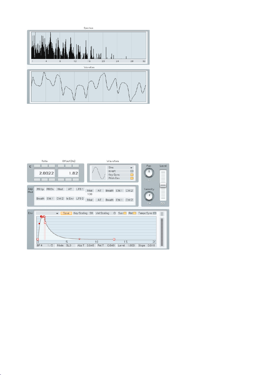
A typical FM8 envelope.
Use the powerful and accurate multi-stage Envelopes to get the sound moving
and to gain tight control over the timbral changes. Examples could be an
evolving pad sound that fades several Operators in and out via slow moving
envelopes or a dissonant sound that smoothes out in its decay phase.
Another approach for moving sound are the FM8’s LFOs that can add simple
vibrato and tremolo effects but can also be the source for complex changes
in harmonic content when you use them on modulators.
10 – FM8
Page 11

3.2.3. Morphing Sounds
The FM8 takes vivid sound and evolving textures a step beyond with its Morph
Square.
The Morph Square in action.
With the Morphing function you can melt four different sounds into one
interactive sound eld.
The basis of the FM sound always is the FM Matrix (see above) and the different
matrix settings of different Sounds can be smoothly morphed into each other
in real-time. This leads to sound transitions that cannot be accomplished via
conventional means like fading in and out.
3.2.4. Arpeggiate
So you want those grooving, pumping, sequenced lines that are so important
for today’s dance music? And of course you want them intuitively playable.
The Arpeggiator – sequence away.
FM8 – 11
Page 12

No problem with the FM8 Arpeggiator. Just play a chord and it will be
transformed, rhythmically re-triggered and transformed into grooving
monophonic synth-lines.
The Arpeggiator is much more exible than its analogue ancestors as in
the FM8 it got injected with a fresh step-sequencing concept. It’s playing a
sequencer like a musical instrument.
3.3. Outline of the Interface
The new design of the FM8 Interface improves on the FM7 with a fresh look
and a host of usability enhancements.
The Interface is divided into four zones:
• The Application Control bar on top of the window.
• The Navigator to the left is for choosing the different Editor windows.
• The Editing Area to the right displays the currently selected Editor.
• The Keyboard is for playing the sound with your mouse.
The following paragraphs only give a very brief introduction into the scope of
the different interface sections. Please read the respective reference chapters
for a detailed description of all parameters.
3.3.1. Global Sections: Application Control Bar, Navigator and Keyboard
The Application Control Bar is the most basic Interface of your FM8. You
can toggle the display of the Navigator/Edit Area and the Keyboard via two
dedicated buttons. You get a mirror of the File menu and a host of status
displays dealing with MIDI, polyphony and the like. Please have a look at the
Reference section for details.
12 – FM8
Page 13
3.3.2. Browser & Attributes Page
The Advent of NI KORE has brought a unied Sound format that is also used in
the FM8 – the KORESound. This also brings a unied interface for managing
Sounds. The Browser is your interface to nding Sounds via a powerful system
of Attributes that characterize each and every Sound of all NI Sound products.
The complete FM8 Sound library has been fully tagged via an extensive system
of Attributes and you can quickly lter and search for any combination of the
provided Attributes or keywords.
Finding the right Sound has never been easier - they’re all in the database.
3.3.3. Master Window
The Master Window provides access to the global parameters of the FM8.
Here you nd things like the main levels, Polyphony settings, global pitch
controls and the MIDI controller assignments.
FM8 – 13
Page 14
3.3.4. Effects Window
The FM8 sports a great sounding selection of Effects processors that can be
combined to produce a variety of professional sounds. The effects range from
classics like chorus and anger over bread-and-butter tools like equalizers and
reverb to a cabinet modelling unit and the crazy Psychedelay.
3.3.5. Arpeggiator Window
The FM8 Arpeggiator combines the old-school Arpeggiator approach with a
exible step-sequencer concept including ties between notes, transposition
of steps and rearrangements of note orders. The results range from classic
arpeggios to rather complex sequences.
14 – FM8
Page 15
3.3.6. Easy/Morph Page
The Easy controls provide a convenient set of macro controls that allow for
sound manipulations without having to bother about the gory details of FM
synthesis. Just grab a knob and change the timbre of your Sound with a single
tweak. You can easily route an LFO to the main pitch or to the harmonic
content or manipulate the amplitude envelope of all Operators at once and
much more.
The Morph Square is a new FM8 feature for seamless morphing between the
timbral characteristics of four FM8 Sounds. You can freely choose those four
Sounds to produce new ones that you would possibly never have gotten when
programming the FM8 the normal way. A randomization function throws in
the possibility for additional variations.
3.3.7. Expert Windows
The Expert Windows offer detailed control of the FM synthesis engine. Here
you can edit and program every tiny detail of the Sound and its movements
over time.
The Expert windows can be divided into two groups. The global group deals
with parameters that can only be set for the complete Sound (like the FM
Matrix and the Pitch window) or showing aspects of all Operators on a single
page (like the Envelopes, Keyscaling and Operators window). The second
group include the dedicated Operator windows showing the various parameters
focussed on the respective Operator.
Depending on the job to be done, both approaches can be the way to go.
Sometimes you have to see all parameters of a single Operator, sometimes
you want to see a special class of parameters for all Operators at once.
FM8 – 15
Page 16
Global Windows
The FM Matrix can be found in almost all Expert windows. It is the heart of the
FM8 synthesis engine where the modulation relationships between Operators
are dened. You can arbitrarily take any Operator’s output to modulate the
frequency of any other Operator using a concise interface.
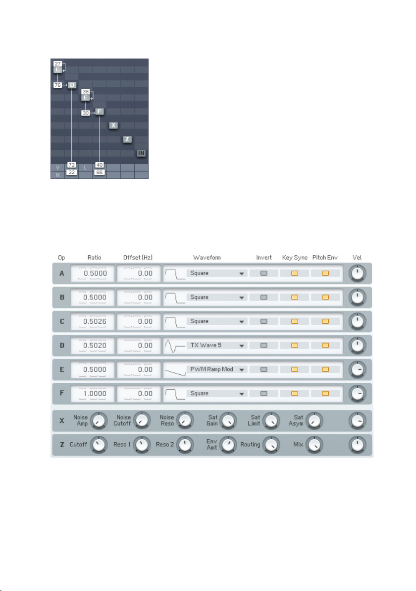
The Operators sub page presents all important parameters of all Operators at
a single glance. Use it to manipulate the Ratios and frequencies of multiple
Operators without getting lost on different pages.
16 – FM8
Page 17
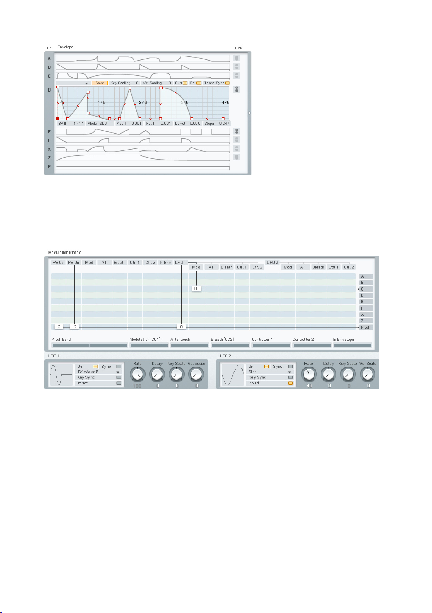
An important aspect of a vivid FM Sound is the Envelopes controlling the
amplitude of modulators and carriers. The Envelope window gives an overview
over all envelopes and still maintains the possibility to edit them. You can
also display a single envelope lling out the complete window or even stack
multiple envelopes in one single graph.
Another way to arrive at lively, interactive Sounds is using modulations via MIDI
or the two FM8 LFOs. The Modulation window shows all current Modulation
assignments of the standard MIDI controllers and the LFO parameters.
FM8 – 17
Page 18
Keyscaling can be very important to make a Sound playable over the complete
range of MIDI notes. Use the Keyscaling window to edit multi-segment
keyscaling graphs for each Operator.
Another function to be found here is the Microtuning editor for producing
alternative tunings.
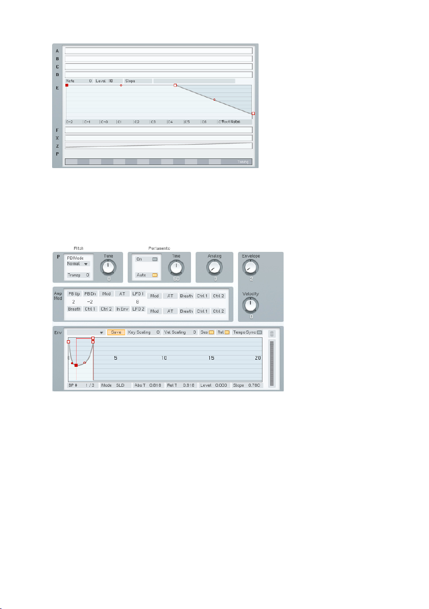
All aspects of pitch are assembled on the Pitch window. Dial in the main pitch,
Portamento and the Pitch Envelope.
18 – FM8
Page 19
Sometimes it’s nice to not only hear sound, but also to be able to actually
see its frequency content. The Scopes are your trusty companions when it
comes to judging changes in timbre due to edits you made somewhere in the
FM8 synthesis engine.
Operator Windows
Each of the Operators has a dedicated page containing all its individual
parameters.
FM8 – 19
Page 20
Operator X is a special one, allowing for the addition of noise and wave shaping
to the signal.
The second special Operator is Operator Z. It offers a great sounding, analoguestyle multimode lter including a lter Envelope.
3.4. Quickstarts
We encourage you to take the time and complete the following short walkthrough
sections. They will help you to understand some of the key aspects of your
FM8.
20 – FM8
Page 21
3.4.1. Loading and Using Sounds
While this is a structured tutorial, if you nd something interesting along the
way, feel free to investigate anything that interests you.
The FM8 Sound Library is organized in a Database providing you with convenient
means for searching and retrieving the Sounds you seek.
Hit the Browser button.
Let’s start right away and open the Browser by clicking on the respective
button on the Navigator.
Toggle the Database View button.
With the Browser open, click the Database View button to yellow to see the
Database View.
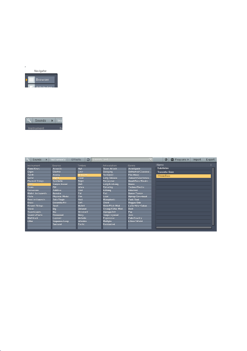
Mining the Library with the browser.
Now the FM8 Library is at your ngertips. On the Browser’s left side are ve
Category columns. These contain the Attributes used to tag, classify and search
all Sounds. These are the same in all NI products using KORESounds.
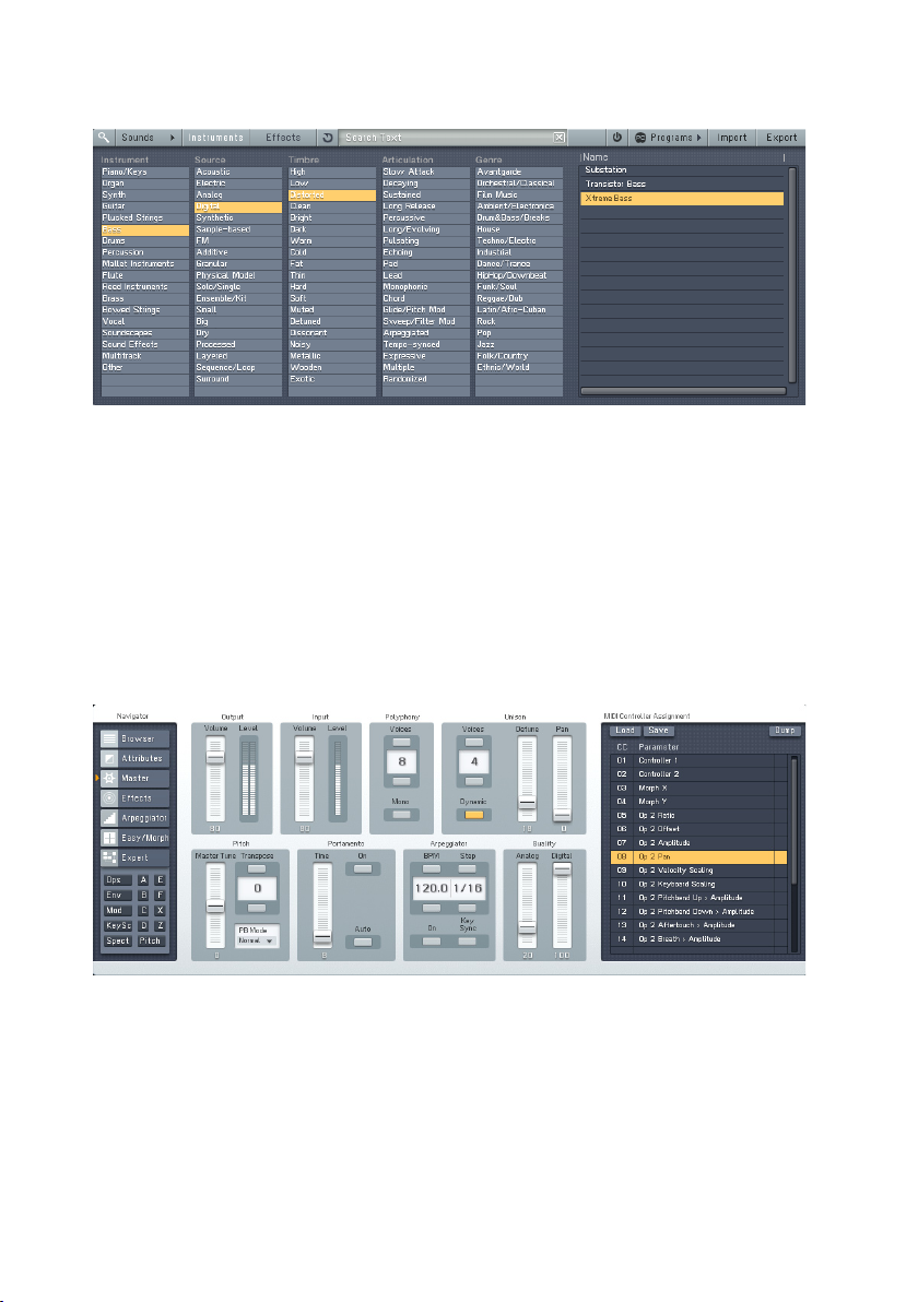
Let’s lter for a classic FM E-Piano. To do this, we combine several Attributes
by clicking them in the Attributes list:
• Click on Piano/Keys under Instrument
• Choose Electric and Synthetic under Source
• In the Timbre Category, click on Bright.
• Under Articulation, we want a Decaying sound
FM8 – 21
Page 22

As you combine Attributes you put more and more constraints on your search,
so the number of Search Results displayed on the right side decreases.
The FM8 Sound Soft Rhodes looks promising, so double-click it.
You can now play the Sound via your MIDI keyboard. If you have not set up
your MIDI connections, please have a look at the Setup Guide for details on
the procedure.
3.4.2. Morphing and Easy Editing
Now let’s check the Morphing feature. We are going to load four different
string Sounds into the Morph Square.
Browsing for Strings.
Open the Browser by clicking on the respective Navigator button and type
Strings into the Search Field. You see a list of string Sounds in the Search
Results.
Drag the Sound to the Morph Square.
22 – FM8
Page 23
Now we are going to drag four of the Sounds into the four quadrants of the small
Morph Square in the Application Control Bar. The rst Sound you drag into
the square will establish all the parameters that are not morphed (envelopes,
modulations, etc.).
• Glass Strings
• Hirez Bell String
• Soft Strings
• Resonant Strings
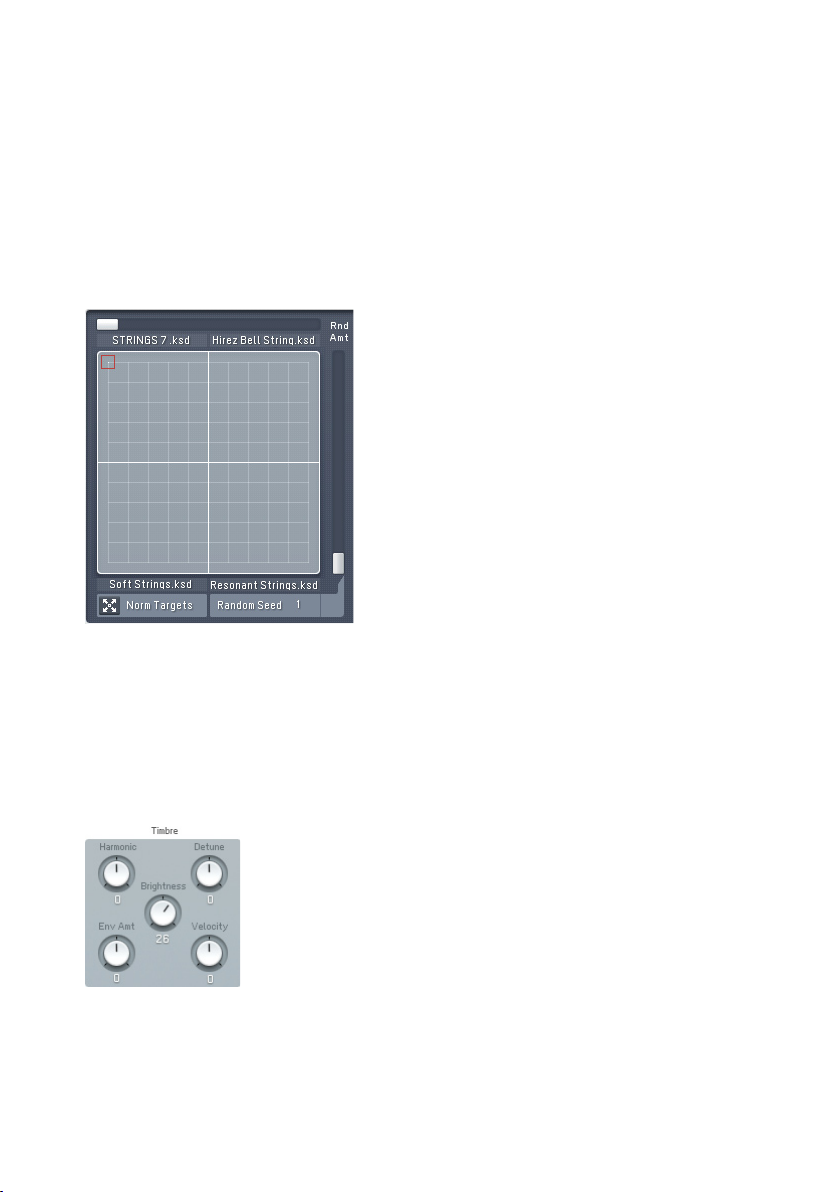
The populated Morph Square.
Please switch to the Easy/Morph window. You see the four Sounds occupying
the four corners of the Morph Square. Play a few chords while moving the
Morph Handle (the small red square). You can hear the sound being morphed
between the four different timbres.
The Sound is a bit on the mufed side, especially with the upper two strings
Sounds. We are going to brighten things up.
Add a bit of sparkle.
Click the Timbre dial and pull it up to a value of 26. If you now play you can
hear all four Sounds getting brighter. The Easy edit macro controls change
FM8 – 23
Page 24
the Sound’s parameters after the morphing has taken place, so it affects all
four corners.
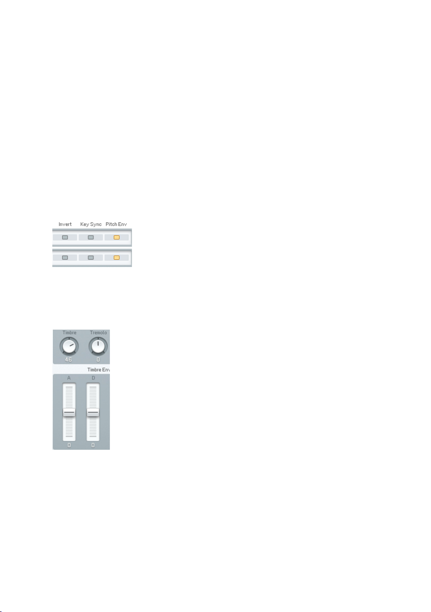
A bit more movement could also sound nice, so we add an LFO to the timbre
of the Sounds.
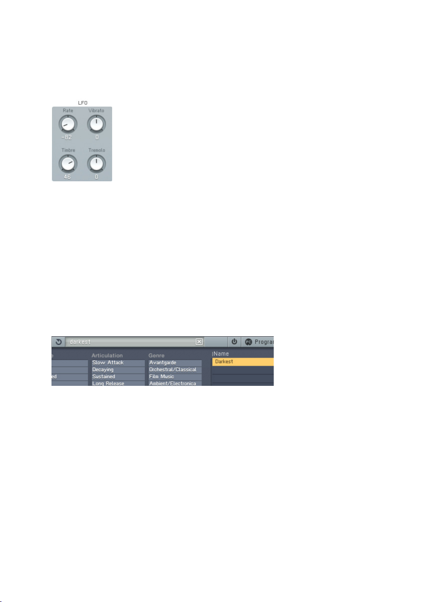
Quick application of the LFO.
Dial in a Rate of -82 and a Timbre value of 46. Now you can hear that the
Sounds have become a lot livelier.
The controls of the Easy window are macro controls. Here you can alter the
sound completely with a few twists and without having to dive into the innards
of FM synthesis.
3.4.3. Using the Arpeggiator and Modifying Attributes
Now to something completely different: the Arpeggiator. As string sounds don’t
lend themselves very well to Arpeggiators, we rst have to nd a different
Sound. Switch back to the Browser.
Loading the bass.
Type “Darkest” into the Search Field. This will nd a nice, analogue sounding
synth bass. Load it with a double-click from the Browser’s Search Results.
Now switch to the Arpeggiator.
24 – FM8
Page 25
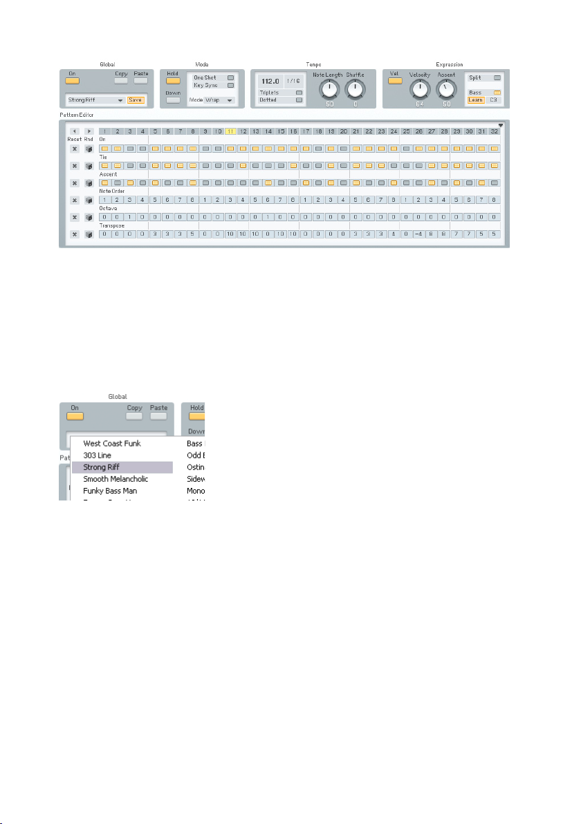
Fun with the sequences.
Hit the On button and lay down a chord on your keyboard.
Now you can start experimenting a bit with the various Arpeggiator settings.
A good start is switching to Autopilot mode (Hold button) to get the hands
free for tweaks.
As the line you hear at the moment might be a bit boring, choose another one
from the Template menu. How about Strong Riff?
Choose your sequence.
Another fruitful set of parameters can be found in the Expression section.
Experiment a bit with the Velocity and Accent settings to get a feeling for
what they do. You might want to deactivate the Velocity switch to have the
Arpeggiator reproduce the velocities you originally played. The Accent dial
sets the amount of accent applied for every accented step on the sequencing
grid.
Next we are going to add a nice effect. Switch over to the Effects page.
FM8 – 25
Page 26

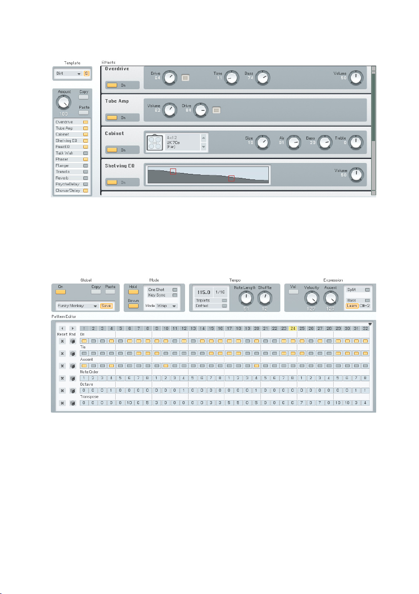
Adding the Talkwah.
A Talkwah is always a nice effect when it comes to adding character to a bass
line. Switch it on via the Effects selector on the left side of the window.
Dial in an Amount of around 70, so that the original bass Sound still shines
through. Now activate the Modwheel option and have some fun with altering
the Mouth value via your modulation wheel.
Now that we have set up our bass line machine, we want to save the Sound
with a new name and with some additional Attributes so that we can nd it
again in the future. Switch to the Attributes window.
New Attributes.
You see the original settings of the Darkest FM8 Sound. Change the name in
the Author eld to your name and add a few matching Attributes to characterize
the changes we made. In The screenshot we added:
• Synthetic under Source
• Arpeggiated for Articulation
• Techno/Electro for Genre.
26 – FM8
Page 27

Save your Sound.
Now save your new Sound by choosing Save Sound from the File menu. A
dialog opens asking for a le name. We chose DarkestArpeggio.
The new Sound is in the Database.
Switch back to the Browser and type Darkest into the Search Field. You can
see the new Sound in the Search Results.
3.4.1. Create your First Sound from Scratch
Now it’s time to design your rst FM Sound from scratch. Of course we are
going to keep it simple and clear.
Initialize the Edit Buffer.
Choose New Sound from the File menu of the Application Control Bar. This
loads an initial sound stored in NewSound.ksd (to be found in the application
folder). If you play a key you will hear a simple and clean sine wave, stemming
from Operator F (unless you already have edited the NewSound.ksd).
FM8 – 27
Page 28

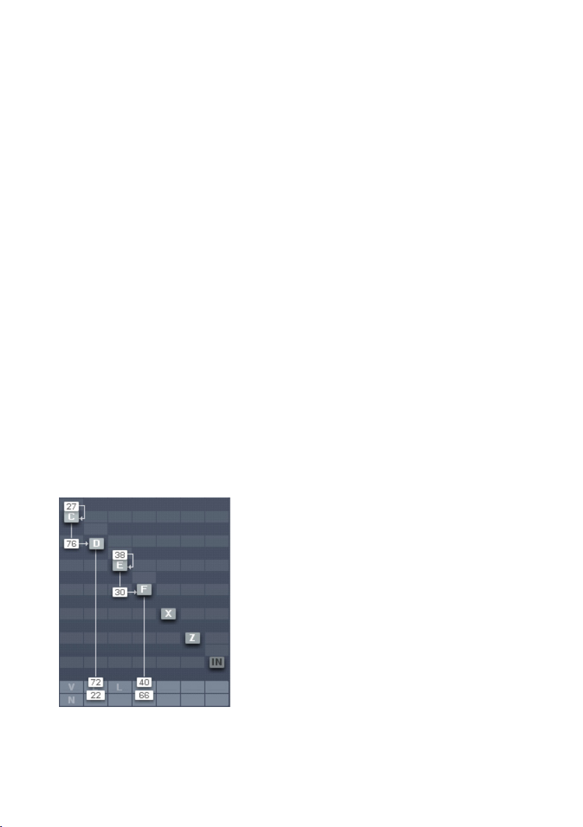
The lonely Operator.
Click on the Operator page of Operator F in the Expert Controls. This sounds
rather dull, so let’s add some harmonics.
Three Operators and some modulation.
Do this by right-clicking Operators D and E to switch them on (the letters
become white). Then click directly to the left of Operator F and drag your mouse
up until you get a value of about 30. Now Operator E modulates Operator F.
The next step is to have Operator D modulate Operator E with an amount of
30. We have a nice little chain of modulators and carriers. You see that a
modulator (like Op. E) modulating a carrier (Op. F) can be a carrier by himself
(like Op. E being modulated by Op. D).
When playing your keyboard you will hear the additional harmonics produced
by the frequency modulation.
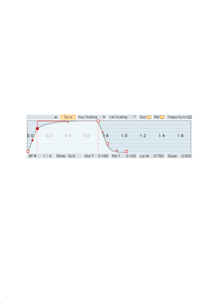
Let’s add some movement to the sound by tweaking the envelopes. Switch
to the Envelopes page (Env).
28 – FM8
Page 29
Now make sure you have Operator F selected for edits and link Operators D and
E to Operator F by clicking on their Link buttons. Now every change you make
to Operator F will be mirrored in the other two Operators and vice versa.
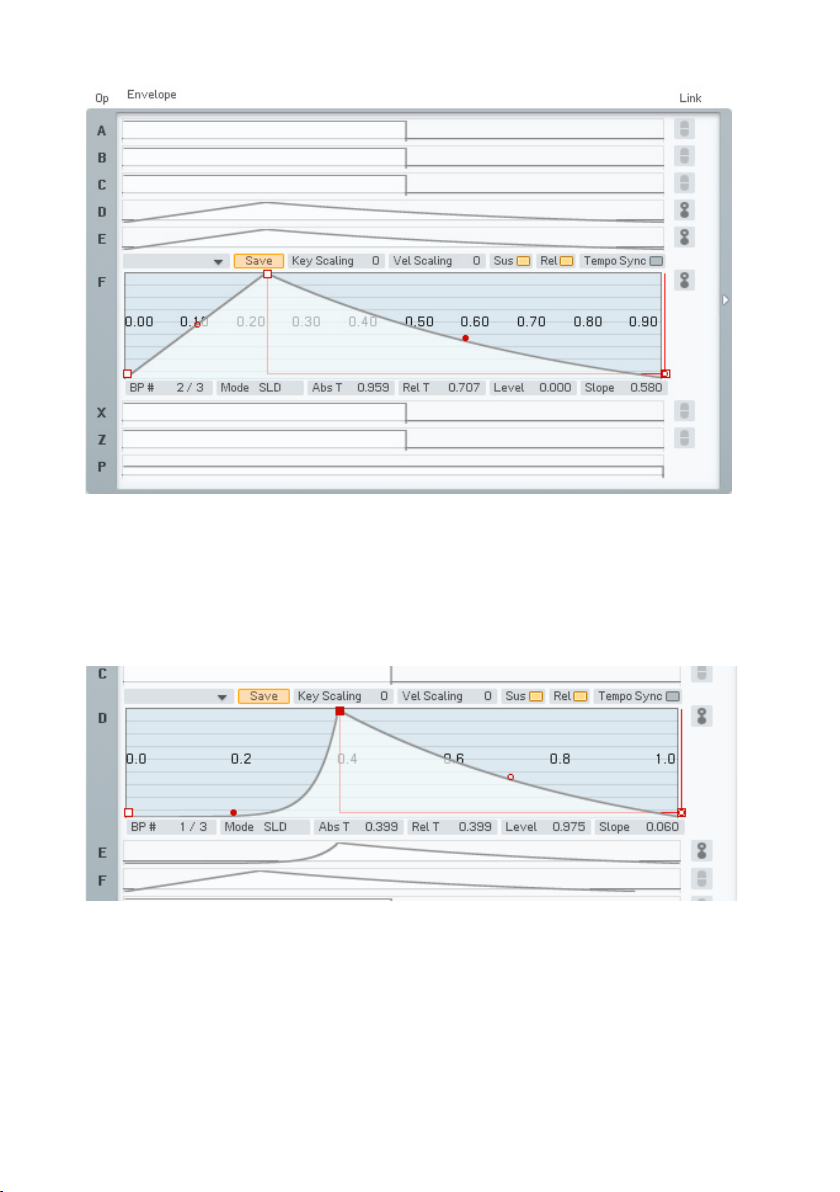
Dial in a bit of Attack and a nice Release, as shown in the picture above.
Remember that you can centre in on the complete Envelope with a doubleclick on the graph. You see that all three envelopes have the same shape.
In the next step deactivate the link buttons and switch to the Envelope of
Operator D. Grab the Slope handle of the Attack phase (the red dot) and dial
in an exponential slope. Play some keys and you will hear that the harmonics
are being faded into the Sound along the Envelope of Operator D, which
is a modulator. This makes the Envelope of Operator D similar to a lter
Envelope.
FM8 – 29
Page 30
Let’s push the Sound a bit more into the woodwind-direction. First of all we
want it to be a bit softer. What could be better than a low-pass lter to soften
things up?
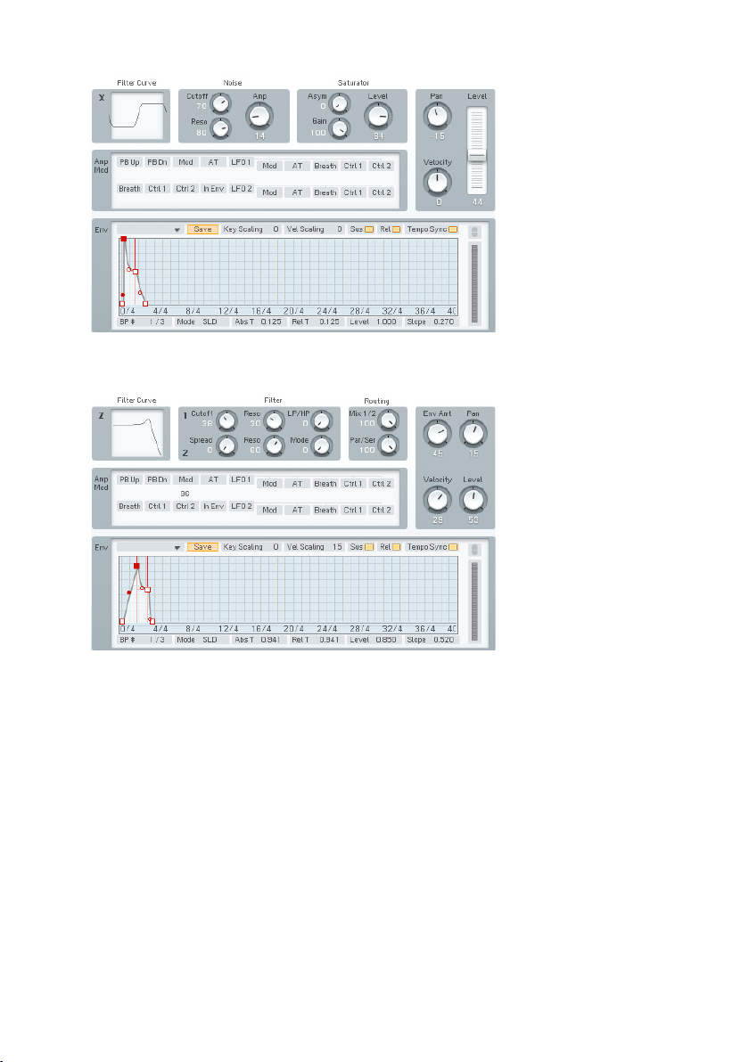
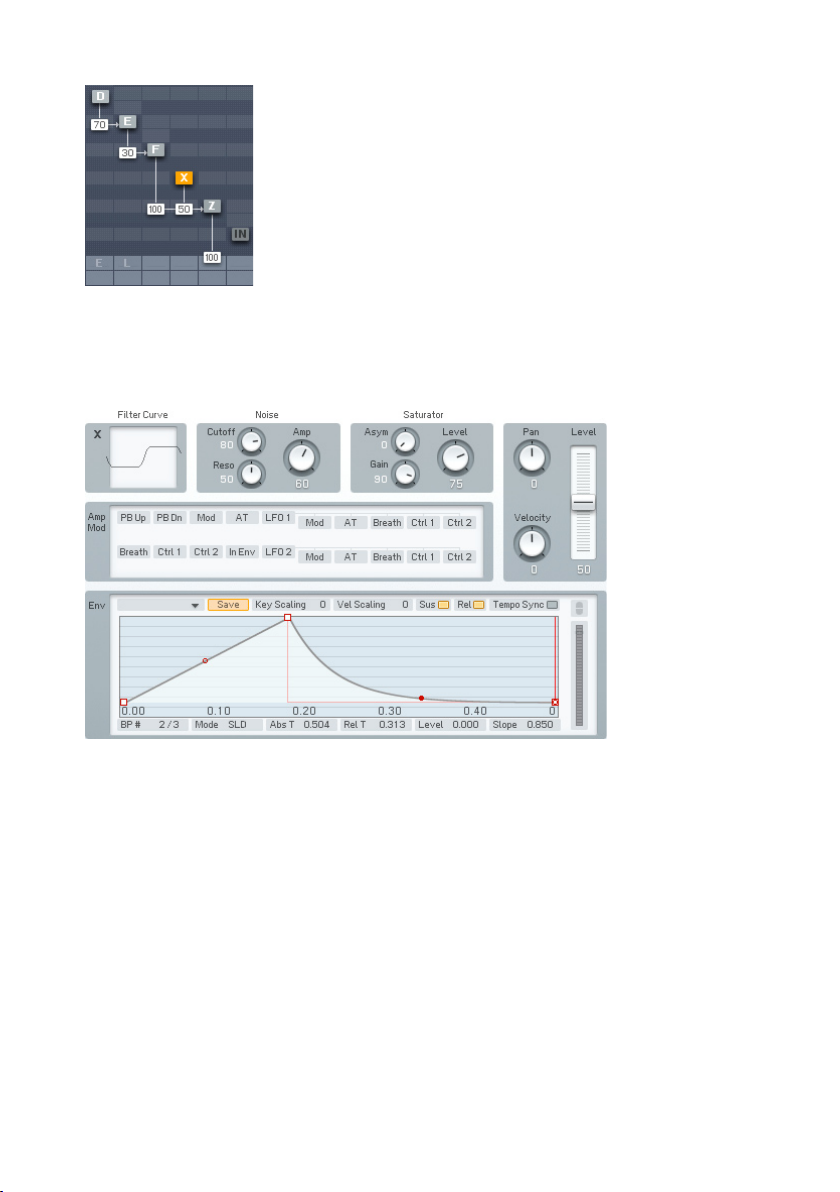
Operator Z joins the action.
The Operator Z contains a great multimode lter, so we just route our signal
through it. Have a look at the picture above for pointers how to do it. Don’t
forget to turn the direct signal from Operator F completely down (a doubleclick on the value is a shortcut for doing this).
Now switch to the Operator Z window.
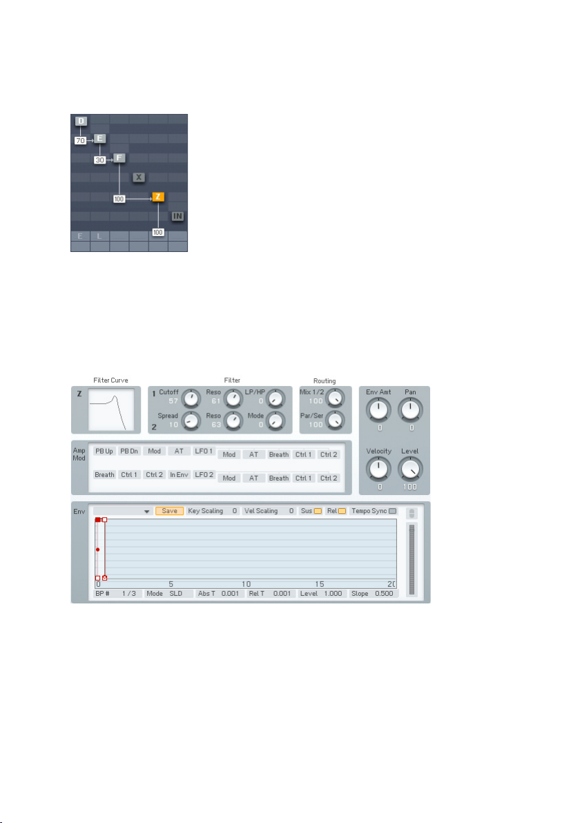
Dial in the lter.
Set the Cutoff to about 60 and the Resonance of the rst lter to about 60.
This setting caps the high mids and highs while adding some character via the
resonant peak. Just have a look at the lter curve to see the response.
We still miss something – the breath. Breathy sounds are usually synthesized
with noise and guess what – the FM8 can produce that too. The noise generator
is located in Operator X.
30 – FM8
Page 31
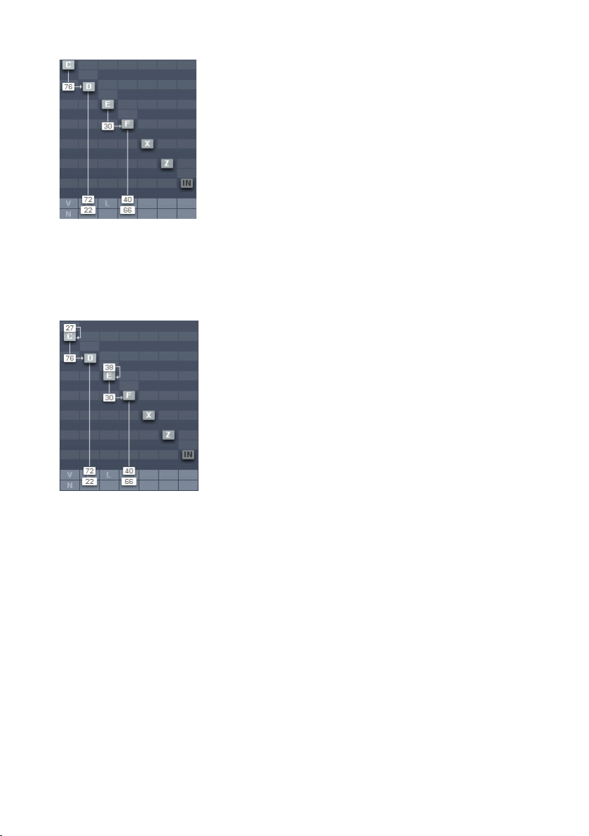
Noise Op to the scene.
Activate Operator X and route its signal through the lter (Operator Z), as
shown in the picture above. Now we switch over to the Operator X window to
tweak the settings.
Noise controls.
Apart from the envelope, the above settings are default values.
We have to change the Envelope to a shape with a small Attack and an
exponential decay phase. We just want a short, soft noise burst at the beginning
of the sound, so you can deactivate the Sustain and Release buttons. Play
some notes to hear the noise being faded in and out at the beginning of the
Sound.
It’s time to save the new Sound but not before we have added a bunch of
Attributes to integrate it into the FM8 Database. To do this, open the Attributes
window.
FM8 – 31
Page 32

Adding some Attributes.
Type your name into the Author eld and add the appropriate Attributes
describing the new Sound. In the picture above we chose:
• Reed Instrument for Instrument
• FM for Source
• Wooden for Timbre
• Sustained for Articulation
The last step is choosing Save Sound from the File menu, type in a name
for the Sound and save it to your Sound folder. We’ll leave the name to your
imagination.
Well, that’s it for now. Just go on experimenting with the new Sound. Maybe
by adding some effects, or an LFO for more liveliness...
32 – FM8
Page 33
4. Reference
4.1. What is Frequency Modulation?
4.1.1. The Basics
The principle behind FM synthesis is of remarkable simplicity. The basis of
all FM synthesis is a sine wave oscillator, represented below as a circle and
an output.
A keyboard or other controller sets the oscillator‘s pitch. However, we now
need a way to gate this oscillator on and off. Analogue synthesizers used a
circuit called a VCA (voltage-controlled amplier) to alter the oscillator level.
The level depended on a control signal (called a control voltage) fed into the
VCA. Many modern digital synths and programs still use this terminology, even
though the level changes are all generated digital, by altering numbers within
the program. Some digital synths refer to VCA as DCA (for Digitally Controlled
Amplier”), while others just refer to it as amp.
With analogue synths, the control signal that changes the level is generated by
a circuit called the envelope generator (EG). It causes the level to change over
time in a predictable way. For example, to create a plucked sound, the envelope
might start at a very high value and then drop over several milliseconds to a
much lower value, or even turn off completely. In digital gear, the program
generates a data stream that changes level the way an envelope generator
would. However, the concept is still usually referred to as envelope generation.
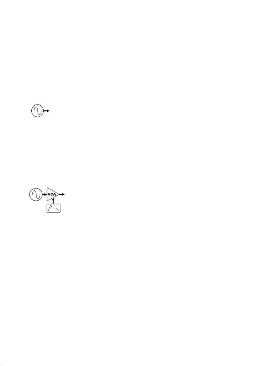
This grouping of a sine wave oscillator, VCA/DCA, and EG is called an Operator,
which is the basic building block of FM synthesis.
As a pure sine wave is pretty boring from a musical standpoint, this leads us
to the extremely clever aspect of FM synthesis. Let’s add a control input to
the Operator to modulate its frequency.
FM8 – 33
Page 34

Feed a sine wave into that control input. A low frequency wave produces
vibrato by slowly changing the frequency over time. But an audio range signal
produces one of two results. Signals that are not harmonically-related to the
main oscillator create “clangourous” sounds. Injecting a harmonically-related
signal generates harmonics that sound more “in-tune” (Both types of effects
can be useful).
The amount of harmonics depends on the level of signal injected into the main
oscillator, and the harmonic structure depends on the modulating oscillator’s
frequency. As timbre is primarily affected by the injected signal’s amplitude,
adding a VCA after the modulating oscillator (along with an envelope generator
to control the VCA/DCA) allows predictable control over the signal, hence the
overall timbre. Our FM synthesis block diagram now looks like this.
Note how the same Operator structure can provide an audio signal (Operator
1) or modulate that audio signal (Operator 2), so we need to differentiate
between the two functions. The Operator we hear is called the carrier. An
Operator is called a modulator if it modulates the carrier.
This two-Operator structure can actually make some very sweet brass timbres.
Increasing the output of Op 2 creates a sound somewhat like opening up a
lowpass lter; decreasing the output is like closing the lter down.
4.1.2. Meet the Algorithm
You can combine Operators in various ways to create a variety of Algorithms.
The FM8 has several preset algorithms, accessible from a drop-down menu
on the FM Matrix window. They use up to six conventional Operators, and you
can see how they are combined in the various macro algorithms. For example,
the following algorithm has two carriers. Each has its own modulator.
34 – FM8
Page 35
4.1.3. Feedback
The next diagram shows the previous algorithm, but with feedback added to
the modulators - in effect, an Operator becomes its own modulator. Increasing
feedback can add bite and grittiness.
Please note that the Input is also present on the FM Matrix. You can use it
as modulator and carrier as if it where a normal Operator. This opens a lot of
new possibilities for using the FM8 as an effects processor.
4.1.4. The Envelope Generator
The envelopes in vintage synths worked on the rate/level principle, which
specied the rate at which the envelope goes from one level to another.
Unfortunately this was quite confusing, as going from zero to a high level
would take longer than going from zero to a low level, given the same rate.
The FM8 solves this problem by letting you set a specic time for one level
to transition to another, and does all the necessary calculations internally to
convert this into the correct rate.
The envelope level typically starts at zero. To create an attack, you specify
the level to be attained, and the time it takes for the envelope to reach that
FM8 – 35
Page 36
level. Other stages of the envelope are set similarly, according to times and
levels. Going from a higher level to a lower one produces a decay, going from
lower to higher produces an attack.
4.2. Interaction with the GUI
4.2.1. Mac and Windows Conventions
Operating the FM8 on Mac or Windows machines is identical, with some slight
differences due to the way the two operation systems handle le systems and
keyboards. Key commands are given for Windows. For the Mac, when the text
says “right-click,” you may also use Ctrl-click.
4.2.2. Buttons and Switches
Click once on a button or switch to activate it, click again to de-select or
disable. An active switch will change its colour to orange.
4.2.3. Faders and Knobs
To change a slider or knob setting, click with the mouse and drag it up or
down to change the value. For ne tuning, press the Shift key prior to moving
the element, and keep holding the Shift key while moving the slider. You may
also double-click on the value for direct editing.
A double-click on the control resets the value to default.
36 – FM8
Page 37

4.2.4. Numeric Values
For value tweaking, click on the numeric readout below the slider. Drag the
mouse up or down to change the value. When there is both a slider and a
numeric value, you get ner resolution by dragging the numeric value. Hold
the Shift key to get an even ner resolution.
For setting up the parameters Ratio and Offset dragging on the 1s digit of the
numeric readout will change the value in 1s. If you drag on the 10s digit, the
value will change in 10s.
If the numeric value has buttons above and below, clicking on the top button
raises the value by one, and clicking on the bottom button lowers the value
by one. Clicking and holding on these buttons scrolls through the values at
a moderate rate.
You can also double-click on a value and type in a new one via your computer’s
keyboard.
4.2.5. Popup Menus
There are two types of popup menus in FM8. The rst type is for preset-type
menus, as with the waveform selection for the Operators. The other one can
be found in the Template selection sections for envelopes, the Arpeggiator or
the Algorithm selector.
For both types, a click on the triangle will open up the menu and a click on
the desired item will load it.
FM8 – 37
Page 38

4.2.6. FM Matrix
The following mouse operations and key commands are available in the
Matrix:
• A click on an Operator selects the appropriate Operator page.
• Right-clicks (Mac: Ctrl-clicks) on Operators switches them on and
off.
• Shift+Right Click (Mac: Shift+Ctrl click)on Operator X and Z switches
Bypass on and off (if Operator X/Z is active)
Constructing your own algorithms is an easy task with the Matrix:
• To send an Operator output to another Operator input, imagine a line
going downward from the rst Operator. Imagine a second line going
across to the right, to the target Operator.
• Click and hold at the junction of these two imaginary lines, as represented
by a blue eld in the background where you click.
• Drag up. The imaginary lines are now drawn in and a box appears with
a numerical value. This controls the level of the modulator feeding the
carrier. Drag until the numerical shows the desired level.
• Any Operator can feed back not just to itself, but to any other Operator.
To create feedback from one Operator to another, imagine a line going
upward from the rst Operator and a second line going across to the
left, to the target Operator.
• Click and hold at the junction of these two imaginary lines.
• Drag up. The imaginary lines are now drawn in, and a box appears
with a numerical value that acts like a volume control. Drag until the
numerical shows the desired level.
• For removal of a connection, drag its value down to 0 or simply doubleclick it.
38 – FM8
Page 39
4.2.7. Graphical Interfaces
There are some specialty graphical interfaces in FM8.
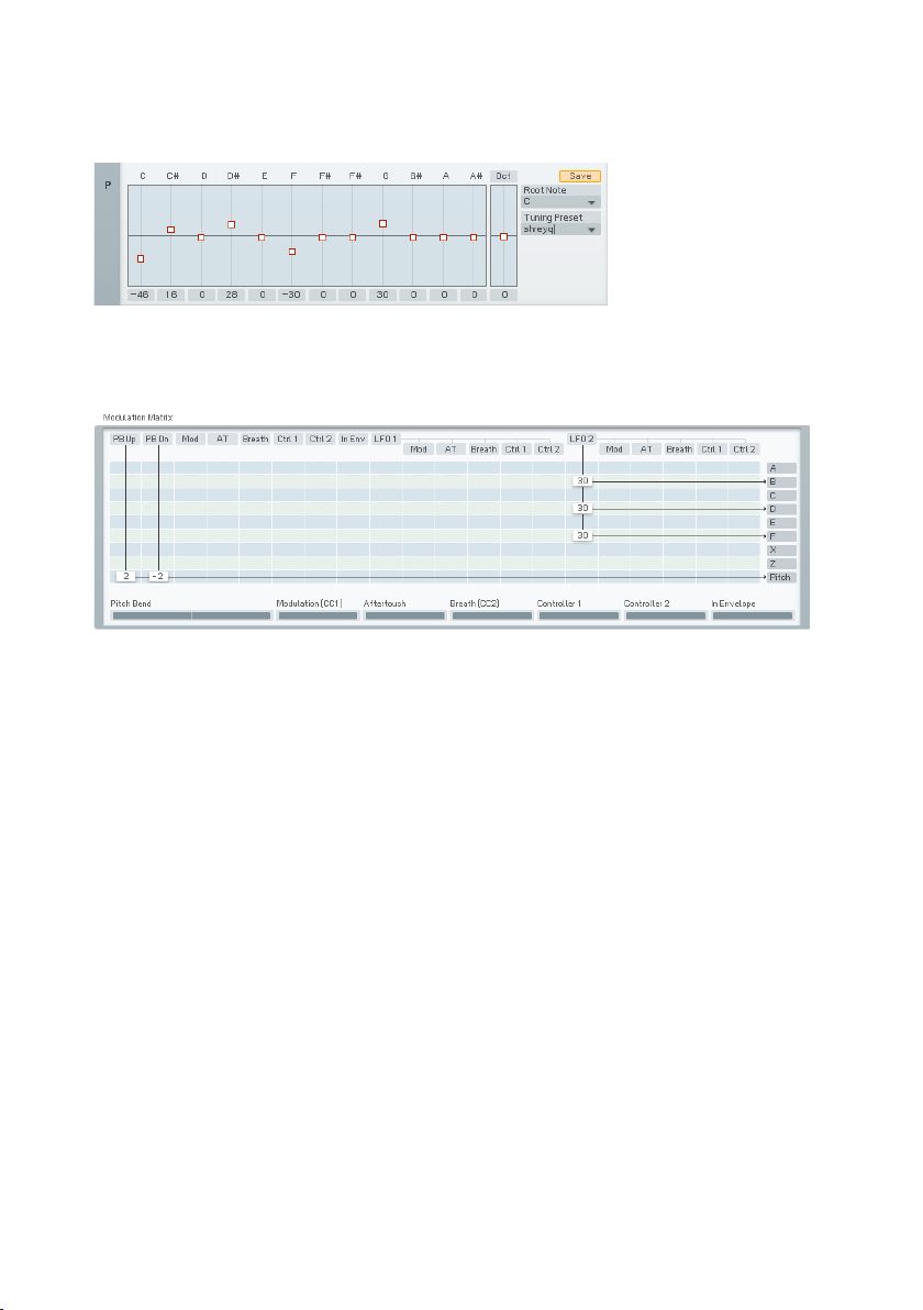
The Microtuning Editor on the Pitch window acts like a bunch of faders. Click
on the small squares and drag the mouse up and down to change the note
tuning.
Another graphical interface can be found on the Modulation window. It works
along the lines of the FM Matrix:
• To send a modulation source’s output to a target input, imagine a line
going downward from the source. Imagine a second line going across
to the right, to the target.
• Click and hold at the junction of these two imaginary lines, as represented
by a eld in the background where you click.
• Drag up. The imaginary lines are now drawn in, and a box appears with
a numerical value. This controls the amount of the modulation applied
to the target. Drag until the numerical shows the desired level.
Modulation amounts can be positive and negative.
FM8 – 39
Page 40

4.2.8. Envelopes
Some parameters, such as envelopes, are shown graphically as curves and
lines with nodes.
• To change an envelope’s shape, click on a node with the mouse, and
drag the breakpoint into the new position.
• To create a new node, right-click where you want the node to appear.
• Drag the Slope handles up or down to change the Envelope’s slope
between breakpoints.
• To delete a node, right-click on the node.
• The ruler behind the envelope is calibrated in seconds. If the envelope
extends past the envelope’s visible range, click on the blue background
and drag to the left or right to see a different range of the ruler.
• Clicking the background and dragging the mouse up or down zooms in
and out.
Double-click on the background to have the envelope t exactly within the
visible part of the ruler.
4.2.9. Pages and Tabs
Most windows you nd in the FM8 are Editors that are switched via the
Navigator and ll out the Editing Area. On some of them (like on the Browser)
you also nd special buttons, called Tabs. Clicking them switches the window
into a different mode, displaying a different page of controls.
4.3. Standalone menus
4.3.1. File Menu
The File menu of the standalone application is mirrored from the Plugin File
menu to be found in the Application Control Bar. For a detailed documentation
please have a look at chapter 0.
40 – FM8
Page 41
4.3.2. Help Menu
Launch Service Center
This command does exactly what it says: It launches the NI Service Center
for managing your NI software licenses. Please have a look at the separate
Setup Guide manual for details.
Visit FM8 on the web
This menu entry opens an external browser window connecting you to the FM8
pages of the NI website. Use it to stay up to speed with the latest information
and development of your FM8.
About FM8
A click on the FM8 or NI logos opens the About FM8 window where you nd
the FM8’s program version number and other information.
The About window can be closed with a click on the close button in the upper
right corner.
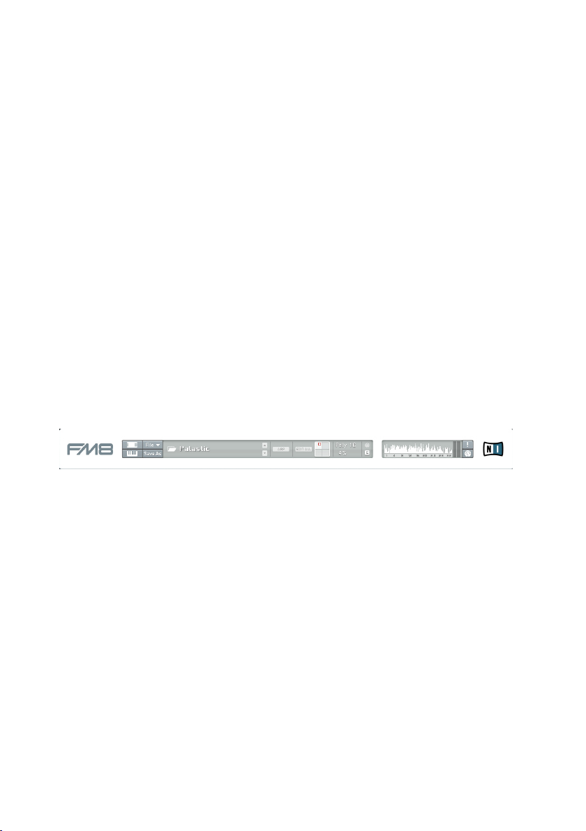
4.4. Application Control Bar
The upper portion of the FM8 remains constant as you switch among the
various Editors. It is also the bare minimum interface of the FM8, as you can
hide the Navigator, the Editing Area and the Keyboard.
4.4.1. Options
The Options window has two tabs.
The General Options tab provides access to some parameters concerning the
behaviour of your FM8.
FM8 – 41
Page 42
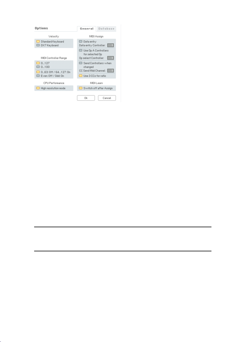
Velocity
The Velocity option toggles between two different modes for the reception of
MIDI velocity. The original DX7 has a note velocity range from 0 to 100, while
all other keyboards and sequencers generate notes with velocities between 0
and 127. If you control the FM8 from a DX7, you can use the DX7 Keyboard
option to adapt the velocity range. With a standard keyboard connected in this
mode, velocities higher than 100 let the presets sound brighter than they have
been programmed. In the Standard Keyboard mode a DX7 would not use the
full dynamic range, so the sounds would be softer than intended.
MIDI Controller Range
Many FM8 parameters have a range from 0 to 100. If you remote control the
FM8 by MIDI control changes it can be advantageous to read the identical
values between 0 and 100 from the remote device. This can be attained with
the 0...100 option; values higher than 100 will be clipped to 100.
Note: this does not apply to parameters that can be negative (like Pan).
In the standard setting, 0…127, the values are mapped to the full range
of an FM8 parameter.
The second pair of switches let you decide how the buttons react to MIDI
controllers. The standard mode is 0…63: Off / 64..127: On, where values
smaller than 64 set the button to the off position, and values greater than 63
set it on. Some MIDI instruments, especially those with multi-step selector
switches, send a value with each change with the sequence being 0, 1, 2, 3,
… Here the Even: Off / Odd: On option can be used so that the FM8 switches
toggle on/off with each action of the remote control switches.
42 – FM8
Page 43

CPU Performance
The High resolution mode enhances the delity of the sound by doubling the
resolution of the internal computations. As a result, aliasing is reduced (in FM
modulation, the X-Operator waves shaping, the overdrive effect or the tube
amp effect) leading to a cleaner and more analogue sound. It also eats up a
bit more CPU cycles. This feature is a global parameter and can’t be saved
with the sound.
MIDI Assign
When Data Entry is activated, selected parameters are outlined and can be
controlled by external hardware via MIDI control changes. Data Entry Controller
sets the number of the MIDI controller to be used for this. Just click on any
knob and then send the MIDI-CC selected in options to change the value. The
Data Entry knob on a DX7 is CC6.
The Use Op A Controllers for Selected Op function allows a page oriented
assignment of MIDI controllers. The controllers assigned to Operator A’s
parameters will control the parameters of another Operator, when you switch
to its page. The switching between Operators is assigned to a MIDI controller
with the number set by Op Select Controller.
Some MIDI hardware allows for incremental control and sometimes the display
of the current state of the values. This has the advantage that knob movements
do not cause any jumps. If you use such a device, enable Send Controllers
When Changed in order to provide the hardware with the latest values set in
the software. CC Send MIDI Channel allows for choosing a separate channel
for these controller events.
The Use 3 CCs for Ratio options provides the possibility to use three different
MIDI controllers to adjust the Operator Ratio.
MIDI Learn
Remember to disable MIDI Learn as soon as a MIDI controller has been
assigned to an FM8 control; this ensures that the assignment will not be
overwritten by later events. But you may want to keep MIDI Learn enabled
should you want to assign several controls in a row. In this case, disable
Switch Off After Assignment to have Learn mode only nished by a click on
the Learn button.
FM8 – 43
Page 44

The Database Tab provides the commands for adding libraries and maintaining
the database.
The User Library Directories are the paths to the folders holding your personal
collections of FM8 Sounds.
• Add chooses a new library to be added via a le dialog.
• Delete removes the currently selected library from your FM8 setup.
• Rebuild DB should be invoked when you make changes to the library
– like adding or removing a new library, or copying new FM8 Sounds
into your folders. Rebuilding the Database can take some time. It’s
best to start a rebuild just before you take a break.
• The name entered under Default Author for Sound DB is used automatically
in the Author eld of the Meta Information if you create a new Sound
or save it.
• Database Hit Count provides a menu that determines the behaviour of
the Browser’s Attributes display. When you lter for Sounds by clicking
various Attributes in the Browser, you put more and more constraints on
the Search Results. For some combination of Attributes, it’s possible
no Sound will t into the current roster of Attributes. With indicate
empty categories chosen, empty categories will be displayed in grey.
The show count as number option additionally displays the number of
Sounds with the current set of Attributes in the various categories. Both
options may degrade the Browser’s performance, so if you experience
a slowdown, switch this menu to none.
44 – FM8
Page 45

4.4.2. Menu Functions and Status Displays
The two switches to the left toggle the Editor and the Keyboard on and off,
respectively. Use them when screen estate is at a premium while working with
various applications and plugins at the same time.
The next bunch of buttons deal with le operations and editing.
The File menu is mirrored from the main application window menus.
You nd the following commands:
New Sound loads an initial FM8 Sound (NewSound.ksd) for you to develop
new content. This le is located in the application folder.
If the currently active FM8 Sound has never been saved before, the Save Sound
opens a File Save dialog. Navigate to the desired folder in your le system,
provide a name and click OK to save the current Sound.
If the Sound has been saved before, the Save Sound command will overwrite
the old version.
Save Sound As… will again provide a File Save dialog, enabling you to save
an existing Sound with a different name.
The Save Sound As… command is also present separately below the
menus.
Options opens the Options window. Please have a look at the separate section
about the Options for more information.
Audio and Midi settings opens the settings window explained in detail in the
FM8 Setup Guide.
FM8 – 45
Page 46

Exit closes the FM8 application.
The Sound Readout displays the name of the current Sound. Use the two
arrows to the left to step through the list of Sounds. Depending on where
the Sound was loaded from, this will either be the current Search Results in
the Browser, the Program change list or the respective folder on your hard
disk. You can also click on the Sound’s name to get a dropdown menu for
immediately switching the Sound.
The ARP switch toggles the Arpeggiator on and off. Have a look at chapter
4.9 for details about the Arpeggiator.
With Edit All inactive, any parameter edits you do are only affecting the timbre
residing in the currently active corner of the morph square. The Morph Square
does not hold complete Sounds but only their timbres (see chapter 4.10.6 for
more). The respective quadrant is selected by moving the morph handle into
its boundaries. With active Edit All option, the parameter edits are affecting
all four Sounds at the same time (for details check chapter 4.10.6).
Note: Please be careful with the Edit All option. It’s very easy to forget
that it is on and therefore to accidentally change timbres.
This Edit All option is deactivated automatically when a new Sound is
loaded.
The Morph Square is the place to set up your morphed Sounds. Drag the
Sounds from the Browser to the desired quadrant of the square to set up
the morph targets. The square is fully functional. Grab the handle to morph
between the four Sounds.
Next on the Application Control Bar is the MIDI Data Display. This display
lights up whenever incoming MIDI data is detected.
The Edit Display always shows you if the current Sound has been altered. If
you have changed something, it will light up.
The Spectrum Display of the Application Control Bar is a mirror from the
Spectrum page. It is for reference purposes and displays the overtone spectrum
of the Sound. The numbers represent the harmonics. This can be very useful
for analysing frequency content relative to parameter changes while editing
a sound.
46 – FM8
Page 47

Poly sets the available polyphony, i.e. the maximum number of voices that FM8
is allowed to generate at any one time. Click on the value and drag up or down
to change it. The maximum value for this parameter is 64. Only voices that
are being played consume CPU cycles, so this parameter acts as a governor
to set a limit on the number of voices and thus on the maximum CPU load.
The Polyphony setting is not stored or recalled as part of a Sound. It should
be set to a value appropriate for the clock speed of the CPU.
The current CPU Load as a percentage of the full load is shown under the
Polyphony display. This is of course non-interactive.
To the right of the Poly and CPU display you nd the Output Level meters
depicting the current level of the main FM8 signal.
The exclamation mark is the Panic button. Should you experience MIDI glitches
resulting in hanging notes, hit this button to kill all sound instantly (including
any reverb and delay responses).
The MIDI Learn button provides an easy means to assign MIDI controllers to the
various FM8 parameters. When the button is active, just move the parameter
you want to assign and directly afterwards move the hardware element on
your controller. The assignment is stored automatically.
4.5. Navigator
The Navigator is your main tool in switching around the FM8 interface. Use
the Navigator buttons to switch to the respective Editors. They are displayed
to the right of the Navigator on the Edit Area.
FM8 – 47
Page 48
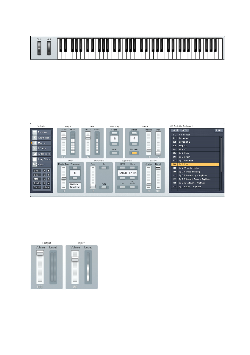
4.6. Keyboard
The virtual Keyboard of the FM8 is for testing out sounds when there’s no
hardware keyboard available. Use your mouse to play. The Pitch Bend and
Modulation wheels are also active.
Your computer keyboard also generates MIDI notes. Type on the letters
(QWERT…) to play the FM8.
4.7. Master Window
The Master Window provides access to the global parameters of the FM8.
Here you nd things like the main levels, Polyphony settings, global pitch
controls and the MIDI controller assignments.
4.7.1. Level Controls
Output Volume changes the level of the entire instrument. Try to keep this as
high as possible, consistent with not overloading the device (e.g., mixer or
soundcard) being fed by the FM8 (as indicated by the associated meter hitting
48 – FM8
Page 49
0 dB). This parameter is not stored or recalled as part of a Sound.
Input Volume controls the level of signals being fed into the FM8 when using
it as a processor. As with output, keep the control as high as possible without
causing the associated level meter to hit 0 dB. This parameter is not stored
or recalled as part of a Sound.
Please note that the Input is also present on the FM Matrix. You can use it
as modulator and carrier as if it where a normal Operator. Of course you will
have to connect the IN Operator’s output to something to hear it.
If you want to process the input without any FM action and pass it through
the effects simply connect it to the OUT of the FM matrix.
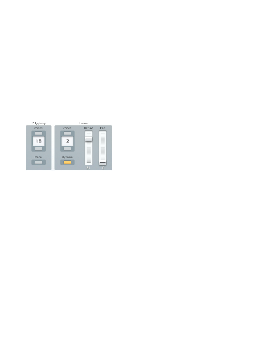
4.7.2. Voices and Polyphony
Polyphony sets the available number of voices. Only voices that are being
played consume CPU power, so this parameter acts as a governor to set a
limit. This parameter is mirrored by the Poly parameter in the main (top) panel
display. It is not stored or recalled as part of a sound.
Mono limits playback to one note at a time, as in the old monophonic, analogue
synthesizers. Like in the DX7 this also switches to single trigger envelopes
(legato playing). However, you can still stack multiple voices on this one note
using Unison (see next).
Unison Voices determines how many voices are stacked on a single key in
unison mode. With Dynamic activated and many keys being pressed without
enough available voices, the FM8 assigns fewer voices to each key, so individual
notes “thin out” rather than disappear.
The Dynamic switch controls what happens when unison voices are selected,
Mono is turned off and several notes are played at the same time.
• With Unison Dynamic switched of f, each new note uses the number
of unison voices specied, if necessary voices are stolen from other
notes already playing.
• When Unison Dynamic is on the voices are shared equally between the
notes. In this case the unison effect thins out gradually as more notes
FM8 – 49
Page 50
are being played. Example: Unison Dynamic on, 8 Voices, 3 Unison
voices, 4 Notes are played: each note gets 2 unison voices.
Unison Detune detunes the unison voices for a fatter, chorus-like effect. Higher
values give increased detuning.
Use the Pan Parameter to distribute the stacked voices over the stereo
panorama. This can produce nice three-dimensional effects.
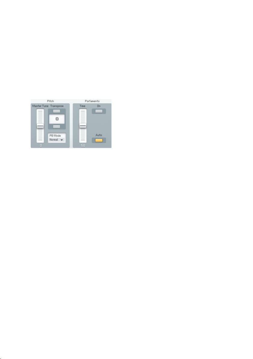
4.7.3. Pitch and Portamento
Master Tune offsets the pitch from -99 to +100 cents for precise pitch matching
to other instruments. This parameter is not stored or recalled as part of a
Sound.
Transpose can transpose pitch up or down two octaves, in semitone
increments.
Portamento On enables or disables the portamento function.
Portamento Time sets how long it takes for the pitch to glide from one note
to another. 0 = shortest time, 100 = longest time.
Portamento Auto allows portamento to occur only when playing legato, i.e.
when there is no gap between played notes. If you release a key before
playing the next one, there will be no portamento. The auto portamento
mode is especially useful in combination with the Arpeggiator Tie parameter.
Tied notes are played legato and therefore get portamento. This is fun when
programming 303-style lines.
50 – FM8
Page 51
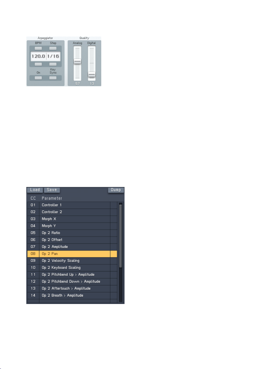
4.7.4. Arpeggiator and Quality
The Arpeggiator controls are mirrored from the Arpeggiator window. Please
have a look at chapter 4.9 for details.
Analog introduces random variations between voices. This used to happen
with analogue gear – e.g. component values would change as temperatures
drifted, and so on. Higher values increase the degree of randomness, and are
very effective in Unison mode.
Digital changes the bit resolution, and therefore the sound quality. The original
DX7 was a 12 Bit device, whereas later models used 16 bits. This control
lets you simulate the “vintage” sound and the resolution can even go lower
than 12 Bit.
4.7.5. MIDI Controls
The MIDI controls display a list of currently assigned MIDI controllers. The
left column shows the controller number and the right column displays the
assigned FM8 parameter.
FM8 – 51
Page 52
Click an assignment with the mouse to select it and hit the delete key on your
keyboard to delete the assignment from the list
Double-click on a controller number and you can change the value.
The Load and Save commands are used to load and save a complete set
of assignments from and to the hard disk. The le ending for assignments
lists is f8c.
You can assign the parameters via the MIDI Learn function on the Application
Control Bar. Please refer to chapter 4.4.2 for details.
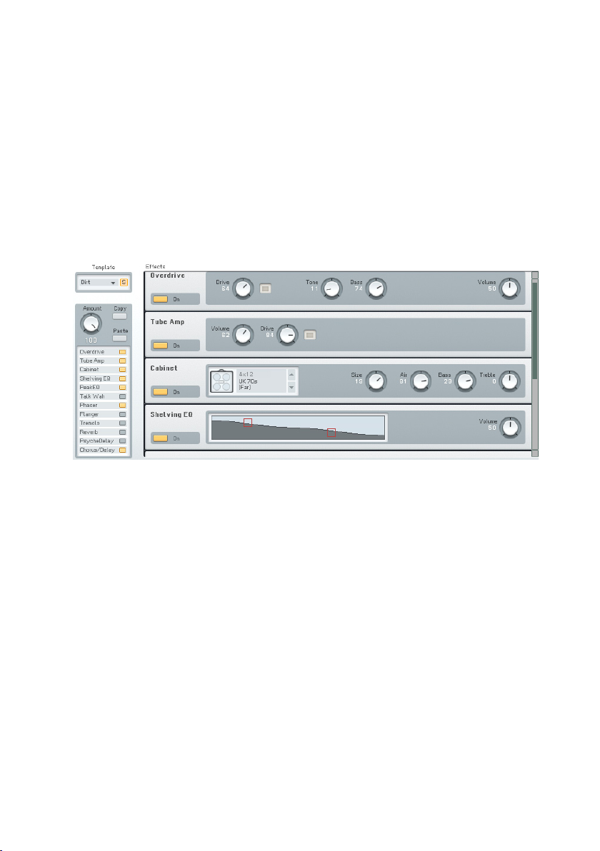
4.8. Effects Window
The FM8 provides a complete set of high-quality effects to be used in your
sound designs. The Effects units are displayed in a rack of virtual devices
and the signal ows serially from top to bottom.
On the upper left of the Effects window you nd the Effects Template system.
Click on the small triangle to see the current list of Templates. If you want
to save your own creation to the list, you have to name it rst. A click on the
name creates a cursor and you can type in the desired name via your computer
keyboard. Clicking on Save opens the Templates list for choosing the slot you
want to save the Template in.
The Amount dial controls the overall effects volume of the complete rack
including all effects units. It acts like a crossfade between wet and dry signal.
The wet signal is the signal after it has been processed by the effects and
the dry one is without processing.
The following section provides a reference for all Effects units. You can
individually switch them on and off with the respective On switches on the
Effects unit itself or on the Effects Navigator. The Navigator is also mirrored
on the Easy page.
52 – FM8
Page 53

4.8.1. Overdrive
This overdrive effect produces a warm and smooth distorted sound.
Parameters
• Drive determines the “crunch factor.” Turn clockwise for more
distortion.
• Turning Tone clockwise provides a bright and screaming sound. Counter-
clockwise turns lead to a mellower, darker sound.
• Bass provides control over the lower frequency tone.
• Volume sets the Effect’s output level. It acts like a master volume
control.
4.8.2. Tube Amp
The Tube Amp simulates a tube guitar amplier.
Parameters
• Volume sets the output level sent from the amplier model. This
determines the overall volume of the sound and it is strictly a volume
adjustment without effect on the tone of the amp.
• Drive determines the preamp level sent to the main tube amp model.
At high levels, this will force the tube amp into overdrive distortion.
4.8.3. Cabinet
The Cabinet Effects simulates a guitar cabinet. Combined with a Tube Amp
you can simulate a complete guitar amp.
FM8 – 53
Page 54
Parameters
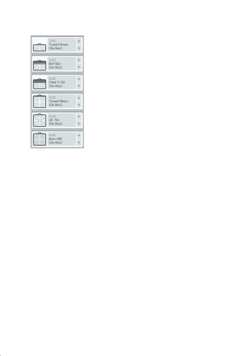
The Cabinets menu is for choosing the different cabinet models. Click on the
small arrows to switch through the following models:
• Tweed Green 2x12 (On Axis)
• Brit 60 2x12 (on Axis)
• Chief V-30 2X12 (On Axis)
• Chief V-30 2X12 (Back)
• Tweed Alnico 4x12 (On Axis)
• Tweed Alnico 4x12 (Far)
• UK 70s 4x12 (On Axis)
• UK 70s 4x12 (Far)
• Bass-WR 4x10 (On Axis)
• Bass-WR 4x10 (Horn)
The comment in brackets states the placement of the virtual microphone and
the numbers behind the name (4x10, etc.) depicts the speaker conguration
of the cabinet.
• Size does the equivalent of “growing” or “shrinking” the cabinet and
speakers. For example, with a 1x12 cabinet, set Size to -20% and it
becomes a 1x10. Increasing Size to +25% turns it into a 1x15, and
+43% creates a 1x17 speaker/cabinet.
54 – FM8
Page 55
• Air controls the level of early reections in the room response adding
a sense of space to the sound.
• Bass boosts or cuts the level of the lower frequencies.
• Treble boosts or cuts the level of the higher frequencies.
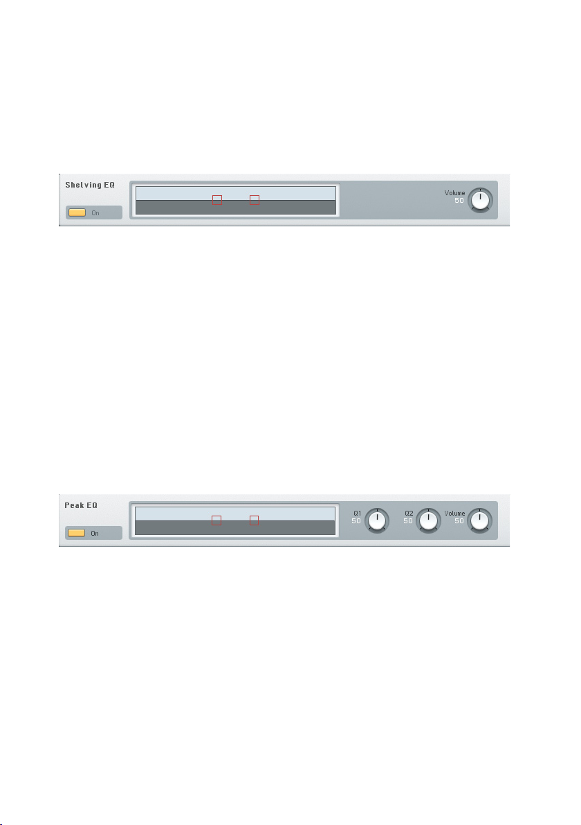
4.8.4. Shelving EQ
A shelving equalizer is a type of tone control that boosts or cuts starting at a
specic frequency. Upon attaining the specied amount of boost or cut, the
response turns into a “shelf” and provides a constant amount of boost or cut
past from that point.
This type of EQ provides general tone shaping to correct broad issues, like
lack of high frequency “sparkle” or excessive “boominess” in the bass end.
The graph in EQ Shelving illustrates the response created by the controls.
Parameters
To adjust parameters click on the graphic display’s dots and drag (up to increase
gain, down to decrease gain, sideways to change frequency).
The Volume dial controls the output level of the Effect.
4.8.5. Peak EQ
A peak or parametric equalizer is a highly sophisticated form of tone control.
Unlike the graphic equalizer which can boost/cut only at specic xed
frequencies, a parametric EQ can boost or cut over a continuously variable
range of frequencies. In addition, the bandwidth (the range of frequencies
affected by the boosting or cutting) is variable from broad to narrow. The
graph illustrates the response created by the controls.
The Peak EQ includes two complete parametric EQ stages, i.e. the rst stage
could boost the bass frequencies around 100 Hz, while the second stage
adds a midrange notch.
FM8 – 55
Page 56
Parameters
To adjust parameters click on the graphic display’s dots and drag (up to increase
gain, down to decrease gain, sideways to change frequency).
Q1 and Q2 edit the width of the frequency band for the boost or cut. Narrow
bandwidth settings (turning clockwise from the centre position) affect a very
small part of the audio spectrum, while broad bandwidth settings (turning
counter-clockwise from the centre position) affect a broader range.
The Volume dial controls the output level of the Effect.
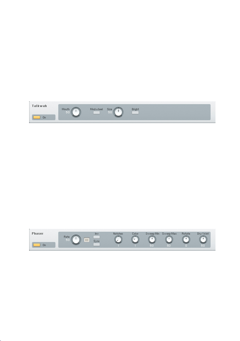
4.8.6. Talk Wah
This is similar to a Wahwah, but uses a different lter type that emulates the
ltering that your mouth creates when enunciating vowels.
Parameters
Mouth controls the Talk Wah frequency. Turning counter-clockwise gives an
“oooo” sound; moving it toward center morphs into more of an “aah” sound,
while going further to the right morphs into more of an “eee” sound.
Size adjusts the size of the “virtual mouth.” When counterclockwise, the
mouth
is small, like that of a midget. When clockwise, it’s like a giant’s mouth.
Bright is a switch that makes the overall sound more trebly.
4.8.7. Phaser
The Phaser adds a swirling, animated effect to the sound.
Parameters
• Rate controls the speed of the phaser effect.
• Invert changes the phase of the shifted signal, producing a different
timbre.
56 – FM8
Page 57

• Sync synchronizes the phaser rate to the host tempo so that it follows
the song’s rhythm. In standalone mode, the phaser rate syncs to the
internal clock.
• Notches determines the number of stages in the phase shifter. Click
on the associated numerical and drag to select from 1 to 5 notches.
• Color creates a timbral change that’s a variation on the standard phaser
sound.
• Sweep Min sets the sweep’s lower frequency limit.
• Sweep Max sets the sweep’s upper frequency limit.
• Rotate alters the phase difference between the LFOs feeding the left
and right channels for a stereo effect.
• Dry Wet adjusts the mix of the dry and processed (phase shifted)
sound.
4.8.8. Flanger
This versatile anger is roughly derived from a legendary analogue effects
box.
Parameters
• Rate controls the LFO frequency. In other words it controls the speed
of modulation.
• An active Inv button leads to a phase-shift of the modulated signal,
thereby changing the timbre.
• Sync enabled synchronization of the LFO to the current MIDI tempo.
• Static toggles modulation of the effect on and off. If switched off, the
anging effect becomes static.
• Depth sets the amount of modulation applied to the effect.
• Color dials in the amount of feedback.
• Rotate produces a spatial effect by shifting the phases of the LFOs for
the two channels against each other. This leads to the impression of
“rotating” the effect in the stereo space.
• Dry Wet controls the balance between effect and dry signal.
FM8 – 57
Page 58
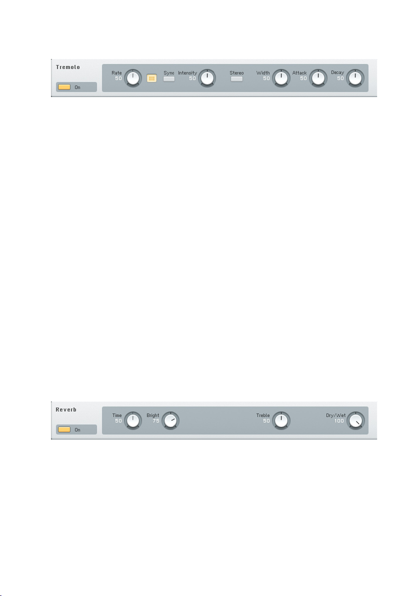
4.8.9. Tremolo
The Tremolo provides a periodic amplitude change leading to a pulsating sound.
A modulation source controls the rate of these amplitude changes.
Parameters
• Rate sets the modulation frequency. Faster settings add a type of
“shimmering” effect to the sound.
• Sync synchronizes the tremolo rate to the host tempo so that it follows
the song’s rhythm. In standalone mode, the tremolo rate syncs to the
FM8 internal clock.
• Intensity controls the tremolo effect depth by adding in some dry signal
to the processed signal.
• Stereo switches between a mono and stereo Tremolo effect. This
interacts with the Width setting (see above).
• Width sets the ratio between the time spent at high or at low volume
when stereo is off, or to the right / left side of the stereo eld when
stereo is on.
• The Attack dial controls the time the Tremolo spends rising up.
• The Decay dial controls the time the Tremolo spends decaying.
• Turning both Attack and Decay to minimum creates more of a hard
gate effect.
4.8.10. Reverb
The Reverb provides a natural-sounding emulation of halls and rooms.
Parameters
• Time determines the decay time of the reverb tail. Turn clockwise for a
large concert hall, counter-clockwise for a small auditorium or room.
• Bright controls the decay time for the high frequencies.
58 – FM8
Page 59

• Treble boosts or cuts the level of the higher frequencies.
• Dry Wet adjusts the mix of the dry and processed (reverberating)
sound.
4.8.11. PsycheDelay
This true stereo delay (both ins and outs are stereo) creates sounds that range
from standard echo/ambient sounds, to reverse-based effects that recall the
“backwards tape” sounds of the 1960s.
Parameters
• Time adjust the initial delay time, from 10 ms to 2000 ms. This
parameter interacts with the Stereo dial. Note that very short delay
times give complex, ring modulation-type tones.
• Tap sets the delay rhythm as you click on the Tap Time button. This
function measures the time between clicks, and uses this value to derive
the tempo. It will also average the time between multiple “taps.”
• Sync synchronizes the delay time to the host tempo so that it follows
the song’s rhythm. In standalone mode, the delay time syncs to the
FM8 internal clock.
• Feedback determines how much of the output feeds back into the
input. Minimum feedback gives a single echo. Increasing this parameter
produces repeating echoes. As noted above under “Detune,” Feedback
interacts with the Detune parameter.
• Reverse causes these additional delays to play back in reverse, like the
main delays when the main reverse button is enabled.
• Stereo, when turned clockwise, creates stereo echo effects. At 1.00,
the delay time is set solely by the main Time parameter. Settings of less
than 1.00 place echoes in the stereo eld, with the number indicating
division (e.g., a setting of 0.50 means that the extra echoes will happen
at half the time of the main delay setting).
• Detune detunes echoes up to ±50 cents. Combining this with
feedback causes successive echoes to have ever-increasing amounts
of detuning.
FM8 – 59
Page 60

• Pitch adds a more extreme amount of detuning by transposing the
echo in semitones, from –12 to +12. It interacts with the feedback
control in the same way as Detune (i.e., each successive echo will be
transposed an additional amount upward or downward, as set by the
Pitch value).
• Dry Wet sets the balance of straight and delay sounds. Completely
turned to the left means dry sound only. Turning the dial clockwise
adds more delay effect.
4.8.12. Chorus / Delay
Parameters
This actually is a 4-tap stereo delay line with four independent modulation
LFOs and the output can be ltered - a luxury Chorus. You can also use it
for nice delay effects.
•
• Time sets the time between repeats.
• Invert alters the phase of the repeats. Inversion gives a somewhat more
diffused sound with echoes and with anging, changes the effect’s
tonality.
• Sync synchronizes the delay time to the host tempo. If Sync is activated,
the modulation LFO is also synchronized to the tempo. In standalone
mode, the delay time syncs to the FM8 internal clock.
• Sync Delay's phase locks the modulation LFOs and diffused echoes.
• Diffusion spreads the 4 echo taps in time. Higher values give more
diffusion. With Time = 55, Feedback = 70, Diffusion = 100, Dry/Wet
= 85, Low Cut = 100, Hi Cut = 40 and Modulation Depth = 20, you’ll
hear a reverb-like effect.
• Low Cut determines the delayed signal’s low end frequency response.
0 gives full low frequency response. A setting of 100 cuts out the low
frequencies.
• Hi Cut edits the delayed signal’s high end frequency response. 0 gives
minimum high frequency response. A setting of 100 gives maximum
high frequency response.
60 – FM8
Page 61

• Feedback causes the delay output to feedback to the input, thus creating
multiple echoes. The Delay Time control sets the spacing between
echoes.
• The two modulation parameters add a periodic, cyclic shift to the delayed
signal time. At low delay times, adding modulation by turning up the
Depth control creates anging effects. At slightly longer delay times,
it’s possible to obtain chorusing. At high values, you can get some really
warped sounds by turning up the Depth.
• Mod Rate sets the period of the LFO modulating the delay time. 0 =
slowest rate, 100 = fastest rate.
• Mod Depth determines how much the modulation varies the delay causing
pitch modulation. 0 = no modulation, 100 = maximum modulation.
• Dry Wet determines the mix of straight and processed sounds. 0 gives
dry sound only, 100 gives effect sound only. 50 is generally the optimum
for chorusing and anging effects.
4.9. Arpeggiator Window
Arpeggiators are an integral part of the synthesizer world since the 80s. The
FM8 extends on this system of semi-automatic pattern production by adding a
step matrix that is derived from step-sequencers. This adds a lot of exibility
and blurs the line between sequencing and arpeggios.
The pattern driven FM8 Arpeggiator is a bit more complex than your average
Arpeggiator to be found in many other synthesizers. Nevertheless, it is still
your note input from the keyboard (or from another sequencer) that is the
basis on which the resulting pattern of notes is constructed.
The notes you play on the keyboard are “projected” on the pattern you construct
with the Pattern Editor. The Editor works like a step sequencer where you can
FM8 – 61
Page 62
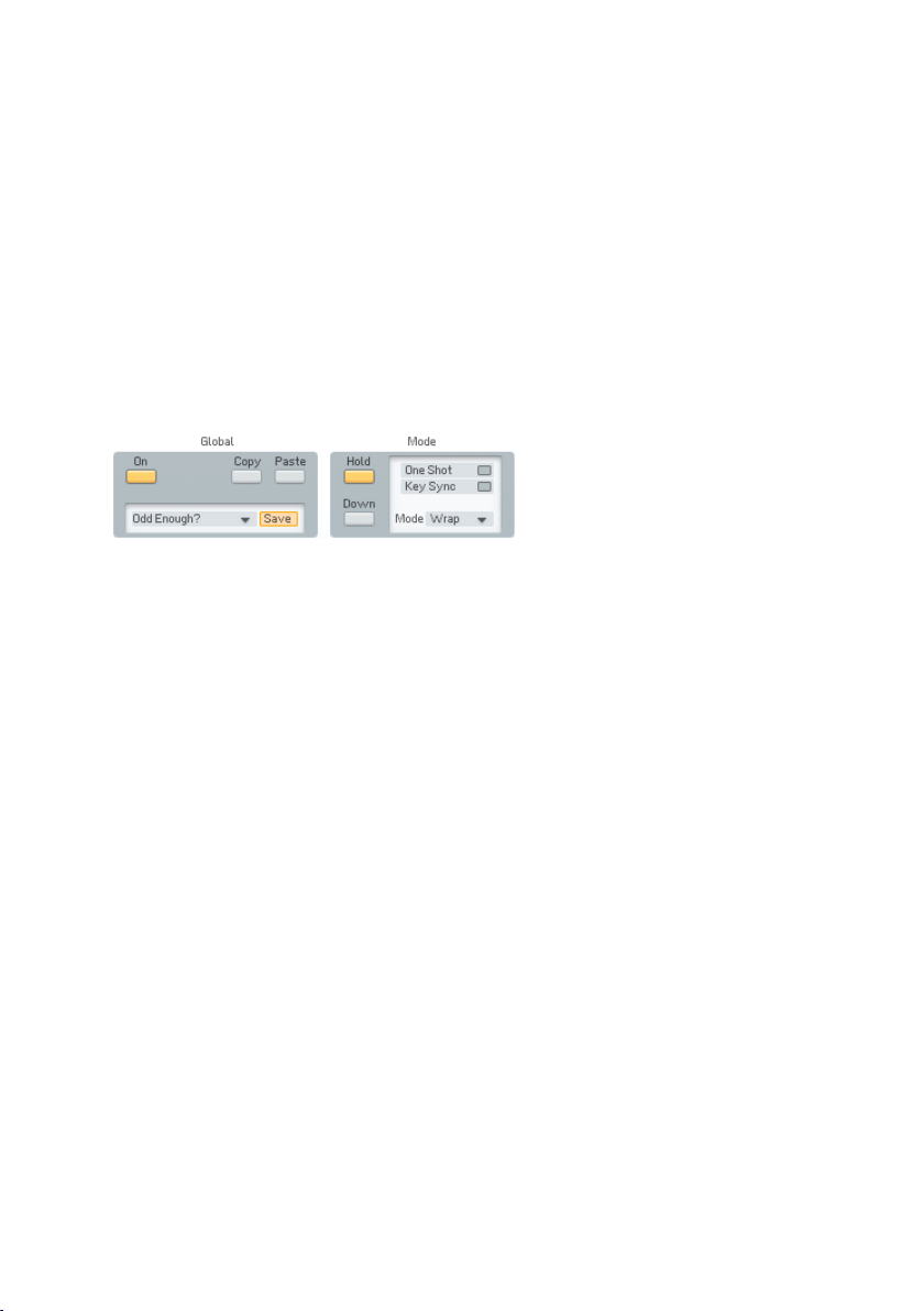
set several parameters for every step of the pattern. The Pattern as dened
in the Editor always runs from step one to the Repeat marker and then starts
over from position one.
You can dene for every step if it triggers a note or not, which of the input
notes is triggered, if the following note gets tied to the current one, if the step
is accented, transposed, etc.
Most of the time there are more steps in the pattern than notes played on the
keyboard. The notes played are used according to the Mode setting leading
to a great variety of sequences. They can be used as an upwards, sequence,
randomly, extended over several octaves, etc.
4.9.1. Arpeggiator Controls
The On button activates the Arpeggiator. The step position is driven by the
clock (internal or host). When you press a note it plays at whatever step it
happens to be now.
Use the Copy and Paste buttons to transfer complete sets of Arpeggiator
settings from one Sound to the other.
The Template system provides access to a variety of preset patterns and is
also the way to go if you want to save your own creations. Find the factory
templates and your own, previously stored patterns by clicking on the small
triangle of the menu. There can be up to 64 stored Templates. For saving
the new Arpeggio, use the Save command. A click on this button opens the
list of Templates. Click on the desired slot and the new pattern is stored.
Please be aware, that the Template already residing in the chosen slot will
be overwritten.
Use the Hold function to let the Arpeggio run even if you lift your ngers from
the keys. You can keep adding notes by holding them down at the same time.
When you let go, they all keep playing. When you then press a rst note, the
old held notes stop and the new note starts playing.
The Down switch selects whether the pressed notes are counted up from the
lowest (default), or down from the highest.
• When off, 1 = lowest note, 2 is second lowest.
• When on, 1 = highest note, 2 is second highest.
62 – FM8
Page 63

With the One Shot Option active, the pattern will run only once and then stop.
This is useful for triggering single phrases. This is most useful with active
Key Sync (see below).
If you have developed a nice new Arpeggio, you can give it a new name with
a single-click into the name eld and subsequent keyboard entry.
Key Sync determines whether the Arpeggio will restart from position one when
a key is pressed or if it will just continue at the position it is currently at (the
Arpeggiator has its own clock that is always running).
Tempo Sync is only functional when the FM8 is running as a plugin in a
sequencer or other host environment. If Tempo Sync is switched on, the
Arpeggiator will synchronize to the current song tempo of the host application.
If you switch it off the Arpeggiator will run with its own clock and the tempo
can be independent from the host tempo.
In standalone mode the Arpeggiator always runs with its own clock and cannot
be synchronized to external software.
The Repeat Mode menu sets the way the Arpeggiator distributes the input
notes on the chosen step grid (see below). As the length is determined by the
pattern, there are many ways how the notes can be used by the Arpeggiator to
build the sequence. Example: the Note pattern goes 1 2 3 4 5 6 7 8, but only
3 notes are pressed: C, D and E. There are nine Repeat Modes available:
• Ping: C D E D C D E D
• Pong: C D E E D C C D
• Wrap: C D E C D E C D
• Wrap+: C D E C+ D+ E+ C++ D++ (+ = 1 octave up, ++ = 2 octaves up)
• Wrap-: C D E C- D- E- C—D-- (- = 1 octave down, -- = 2 octaves down)
• Last: C D E E E E E E
• First: C D E C C C C C
• Random: This chooses randomly from the played notes.
• Pause: C D E - - - - -
The next controls all deal with the tempo grid and note lengths.
Use the BPM Display to dial in the desired tempo of your Pattern. Click with
your mouse and drag it up or down to change the value. Be aware that an
active Tempo Sync will override this setting when running the FM8 in a host
environment.
FM8 – 63
Page 64
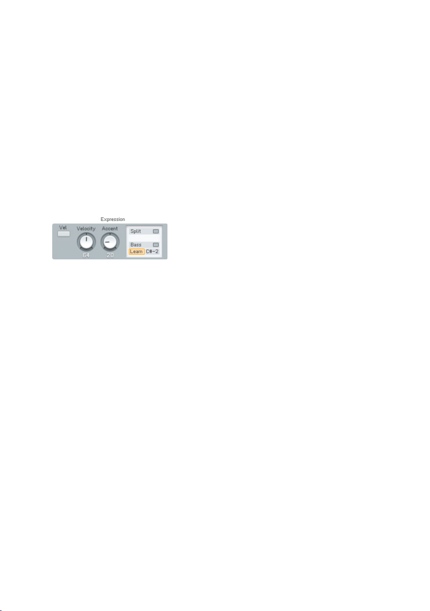
The Time Resolution menu provides ve options for choosing the duration of
the steps. Depending on this setting the Pattern will run faster or slower.
The Time Resolution parameter interacts with the Triplets and Dotted switches,
which are mutually exclusive. Use them to produce triplet or dotted steps with
the step length set by the Time Resolution menu.
The length of the produced notes is controlled by the Note Length dial. The
value displayed means percentage of the current step length, with a default
value of 50%.
With Shufe dialled in, every second step is shifted forward or backward in
timing. At Shufe = 0 (default) these off-steps are exactly in the middle and
the result is the usual mechanically precise timing. With Shufe = 33 you
get a triplet timing 2/3 to 1/3, i.e. the on-the-beat-step is twice as long as
the off-step.
The last group of controls circle around velocity and keyboard split.
The Vel switch activates xed velocity mode. When on, all notes are played at
constant velocity (determined by the Velocity dial), otherwise at the velocity
with which they were pressed.
The Velocity dial determines the Velocity of produced notes when the Vel
switch is on and the Arpeggiator produces only xed velocities.
Control the amount of velocity boost given to accented steps via the Accent
dial.
With active Split, one part of the keyboard is arpeggiated, the rest plays
normally. Set the split point in the Note eld below the Split button or press
the Learn button and hit a MIDI key. An active Bass button causes the notes
below the split point to be arpeggiated. With inactive Bass option the notes
above the split point are arpeggiated).
64 – FM8
Page 65

4.9.2. Pattern Editor
The Pattern Editor is the place where you actually develop your sequences. It
consists of a grid with the columns representing the individual steps and each
row controlling one of the six parameters. The steps and the binary parameters
can be activated / deactivated by single mouse-clicks. The parameters offering
more than one state present a menu with the possible values.
The position on the timeline is shown by a running highlight on the Position
Row on top of the grid. Set the Pattern length by clicking between the numbers
on the Position Row to set the Repeat Marker or drag it directly.
To the left of the Position Row there are two Position Shift buttons that rotate
the contents of the matrix. They move all steps up to the repeat marker to
the left or right by one position. What was the last step before the repeat
marker now becomes the rst step. Everything to the right of the Repeat
Marker stays unchanged.
The On row determines which steps trigger a note.
With an activated Tie on a step, the last note is played legato to tie it to the
one with the Tie. This has two important side-effects:
• When the tied step plays the same note as the step before, no new
Note On message is generated. The old note just continues to sound.
• The Auto-Portamento mode in FM8 is triggered by legato playing. This
means that tied steps will generate a pitch-slide like in the TB303.
With the Accent row you can boost the velocity of individual steps. The amount
of Accent is controlled by the Accent dial (see above).
The Note Order row allows for very complex sequences to be derived from your
note input. The ID number for each step species which of the pressed notes
will be played. The default order is 1 2 3 4 5 6, etc., with the notes being
counted either from lowest to highest or the other way around (depending on
the Down switch). It can be set to the following values:
FM8 – 65
Page 66
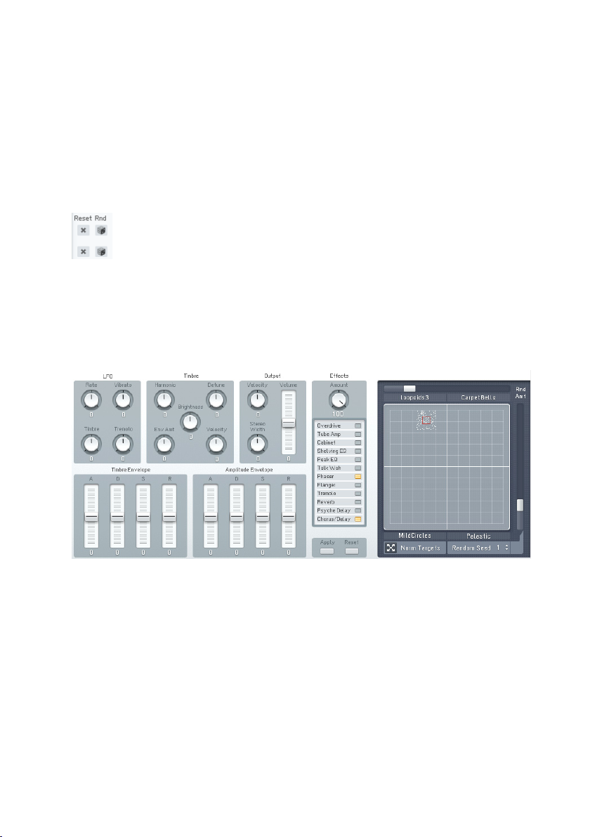
• All: All input notes are triggered at once, so if you play a chord, you
will hear this chord for all steps activated set to All; otherwise the
Arpeggiator always plays monophonic lines.
• Random: One of the pressed notes is picked out at random.
• 1-32: Means that this input note (counted from lowest or highest) is
triggered.
The Octave row allows for transposition of the steps octave-wise up or down,
whereas the Transpose parameter is for transposition in semi-tone steps.
You can reset the individual rows to their default values by clicking on the
Reset buttons and a click on the Randomize button lls the respective row
with random values.
4.10. Easy / Morph Window
FM synthesizers were never easy instruments to program. Familiar synth
parameters were suddenly replaced by a confusing array of Operators,
modulators, rate/level envelopes, and other terms that had no counterpart in
analogue synthesis. No wonder so many people bought third-party sounds!
In designing FM8, Native Instruments has added various helping hands to
make FM synthesis a breeze to program.
For most sounds, the Easy Edit page will be sufcient to customize a sound
for your needs. Just call up a Sound and experiment with the settings to hear
how each one affects the sound.
66 – FM8
Page 67
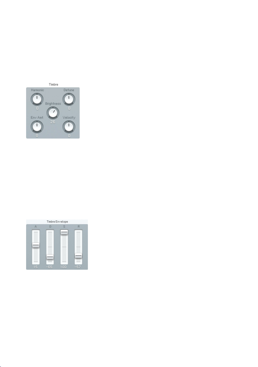
All the Easy Edit sliders go positive and negative, to let you increase or
decrease the relevant properties of the sound. When the sliders are centred
(zero), you hear the original sound.
The various Easy Edit parameters are “meta-parameters” and manipulate a
more or less complex set of FM8 parameters when you use them.
4.10.1. Timbre Controls
Harmonic changes the harmonic content (by adjusting the Operator Ratios).
Depending on the patch, the changed harmonics may be somewhat atonal.
Detune changes the pitch slightly of different oscillators in a multi-oscillator
preset, which creates a fatter sound.
Brightness increases the sound’s high frequency content by increasing the
connection amounts in the FM-Matrix.
Envelope Amount sets how much the timbre envelope inuences the sound.
Velocity Sensitivity determines the extent to which changes in timbre correlate
to the dynamics of your playing.
The FM8 multi-stage envelopes allow for extremely precise control, but are
time-consuming to set up. The Timbre Envelope brings all these parameters
together into the familiar ADSR (Attack Decay Sustain Release) envelope
format. Changing any Timbre Envelope parameter causes multiple changes in
the individual Operator envelopes to accomplish the desired effect.
• Attack Positive values increase the existing attack time, negative values
decrease the attack time.
FM8 – 67
Page 68
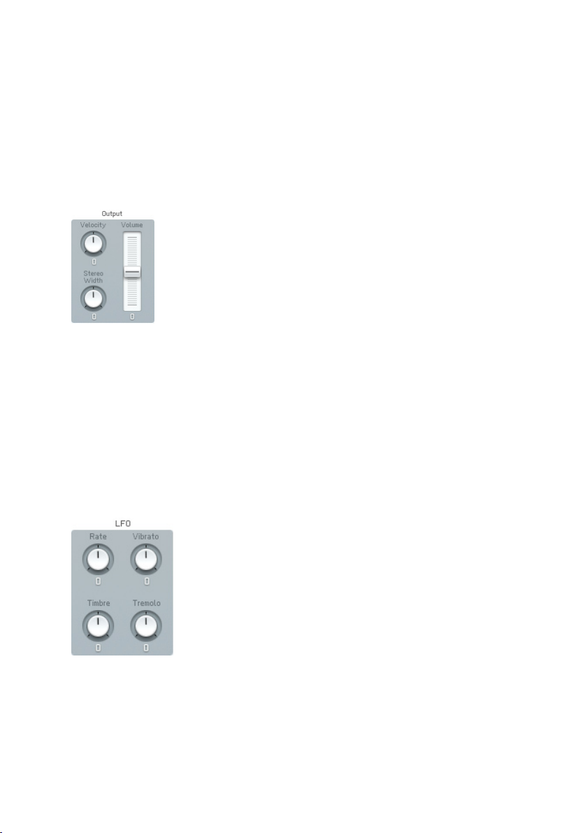
• Decay Positive values increase the existing decay time, negative values
decrease the decay time.
• Sustain Positive values increase the existing sustain level, negative
values decrease the sustain level.
• Release Positive values increase the existing release time, negative
values decrease the release time.
4.10.2. Output Controls
Stereo Width affects the spread of Operators in the stereo eld. Positive values
increase the width to create a wider stereo spread, negative values collapse
the spread to centre (mono).
• Velocity sets how the velocity affects the overall output level. Positive
values increase velocity response, while negative values decrease the
response to velocity.
• Volume changes the overall Sound level. Positive values raise the volume,
negative values decrease it.
4.10.3. LFO and Amplitude Envelopes
As with the envelopes, the LFO parameters tie in with multiple parameters.
Here’s what each control does.
• Rate changes the LFO speed. Positive values increase the speed,
negative values decrease it.
68 – FM8
Page 69
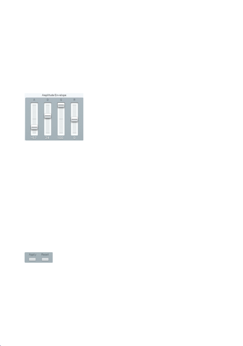
• Vibrato alters how much the LFO modulates pitch. Positive values
increase the amount of pitch modulation, negative values reduce it.
• Timbre determines how much the LFO modulates the frequency response.
In an analogue synth, this is equivalent to altering the amount of lter
modulation from an LFO. Positive values increase the amount of timbre
modulation, negative values reduce it.
• Tremolo sets the extent to which the LFO modulates amplitude. Positive
values increase the amount of amplitude modulation, negative values
decrease it.
This allows tweaking amplitude (level) characteristics in a manner similar to
using the Timbre Envelope to tweak timbral characteristics. Changing any
Amplitude Envelope parameter causes multiple changes in the individual
Operator envelopes to accomplish the desired effect.
• Attack Positive values increase the existing attack time, negative values
decrease the attack time.
• Decay Positive values increase the existing decay time, negative values
decrease the decay time.
• Sustain Positive values increase the existing sustain level, negative
values decrease the sustain level.
• Release Positive values increase the existing release time, negative
values decrease the release time.
4.10.4. Apply and Reset
If you like the edits you’ve made to the sound, click on Apply to store the
edited sound in the Edit buffer. This means that the Easy Page settings revert
to zero, but the relevant sound settings on the other pages are changed so
that you get the same sound. You can go on changing your sound with the
Easy Page from there.
Use Reset to return to the original, pre-edited sound.
FM8 – 69
Page 70
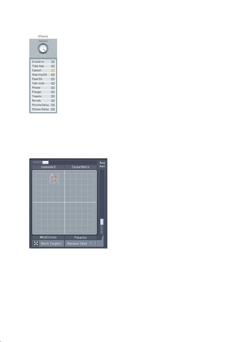
4.10.5. Effect Controls
The Effects controls provide a convenient way to change the Effects setup
without leaving the Easy Page. Just activate or deactivate the various Effects
units by clicking on the respective buttons. The Effects settings will be default
or as saved with the current Sound.
4.10.6. Morph Controls
The Morph Square is your interface to sonically move between four different
FM8 Timbres.
The Morph corners are set up via dragging the Sounds from the Browser to a
quadrant of the small Morph Square you nd in the Application Control Bar.
Once the corner slots are lled with Sounds, you can grab the red square handle
and move it around in the square. The timbre will be morphed to intermediate
versions of the four timbres. Old FM7 sounds have no morphing information,
meaning all corners are the same, and morphing has no effect.
70 – FM8
Page 71

New FM8 sounds have morphing built in so you can load the sound and start
morphing between its corners right away.
You can also morph a single Sound. Load a sound and normalize it (see below).
Select the lower-left corner of the morph square (let’s name it “master corner”).
In this state all four corners have the same timbre settings. Now click on
another corner (let’s name it “timbre corner”) and change some parameters
which can be morphed, e.g. FX Amount. Now you can morph with the handle
between the two parameter settings in the master and timbre corner.
Each corner represents a set of parameters consisting of:
• Operator frequencies
• Operator waveforms (not morphed, but switched)
• Operator X and Z settings
• The Analog & Digital parameters
• FM matrix amounts
• FX Amount
These morphable parameters are marked in the user interface. The following
parameters are not morphed. They exist only once:
• Envelopes
• Keyscalings
• Mono, unison, portamento
• Modulations (LFO, modulation assignments)
• Arpeggiator
• Single FX parameters
You can edit the names of the four morph corners by single-clicking them
and typing in a new one. This can be very useful, as not all parameters are
morphed (see above) leading to a disconnection from the original.
At the right edge and at the upper edge of the square are two sliders labelled
Random Amount. When they are non-zero, a cloud of dots appears around the
handle to indicate the range in which parameters are randomized (each dot
represents one parameter). The two sliders control the height and the width
of the cloud.
Each value of the Random Seed parameter sets a different but reproducible
random distribution (throwing the dice).
The Normalize Timbres button takes the current Morph state and copies it to
all four Slots of the Morph Square leading to four identical Morph corners.
FM8 – 71
Page 72
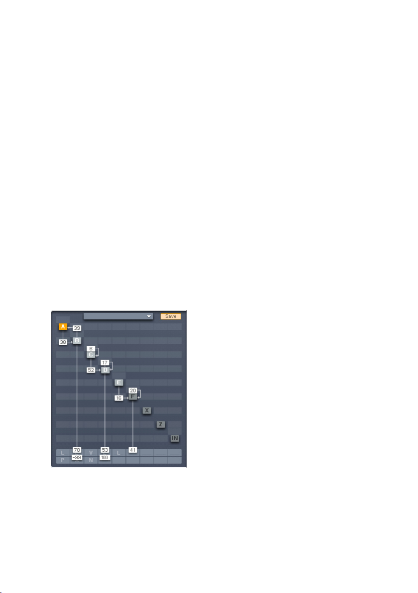
4.11. Expert Controls
4.11.1. FM Matrix
Concepts
Although the FM8 comes with numerous Sounds and can load in presets
from FM synths, learning how to program the FM8 will reward you with
unique sounds that have your own sonic signature. The depth and range of
FM synthesis astonishes, from complex, acoustic-like timbres to wild sound
effects.
Programming starts with an algorithm, and then continues with programming
the various Operators that make up the algorithm. The nal programming step
involves adding effects and tweaking.
Unlike FM synthesizers, which had a xed selection of algorithms, you can
create a virtually innite number of algorithms via the FM8’s programming
matrix. You nd the matrix on all Expert pages, except on the Modulation
page.
The matrix lets you route modulators to carriers, and send carriers to the audio
output. Any Operator can be a modulator, a carrier, or both simultaneously,
and any number of modulators can modulate any number of carriers. Let’s
analyze the algorithm for the Sound Piano 2 included in the FM8 database.
Operator A modulates Operator B, which is a modulator for Operator C.
Operators C, D, and E all modulate Operator F, which serves as a carrier, and
feeds the output. Note that Operator D has feedback.
Inactive Operators are „greyed out“. In the X and Y Operators the letters are
greyed out if Bypass is activated.
72 – FM8
Page 73

Changing Parameters
The following mouse operations and key commands are available in the
Matrix:
• Click on Operator selects the appropriate Operator page
• Right click (Mac: Ctrl click) on Operator switches it on and off.
• Shift+Right Click (Mac: Shift+Ctrl click)on Operator X and Z switches
Bypass on and off (if Operator X/Z is active)
Constructing your own algorithms is an easy task with the Matrix:
• To send an Operator output to another Operator input, imagine a line
going downward from the rst Operator. Imagine a second line going
across to the right, to the target Operator.
• Click and hold at the junction of these two imaginary lines, as represented
by the square eld in the background where you click.
• Drag up. The imaginary lines are now drawn in, and a box appears with
a numerical value. This controls the level of the modulator feeding the
carrier. Drag until the numerical shows the desired level.
• Any Operator can feed back not just to itself, but to any other Operator.
To create feedback from one Operator to another, imagine a line going
upward from the rst Operator and a second line going across to the
left, to the target Operator.
• Click and hold at the junction of these two imaginary lines.
• Drag up. The imaginary lines are now drawn in, and a box appears
with a numerical value that acts like a volume control. Drag until the
numerical shows the desired level.
• For removal of a connection, drag its value down to 0 or simply doubleclick it.
Panning
The lowest row of the FM Matrix holds the panning values for the different
Operators. Pan values range from -99 (left channel only) to 100 (right channel
only).
Panning has no effect on modulations. The Operator has to be a carrier and be
routed to the output for the pan value to work. Pan will also work for operators
routed to the lter operator Z when Z is routed to the output.
FM8 – 73
Page 74
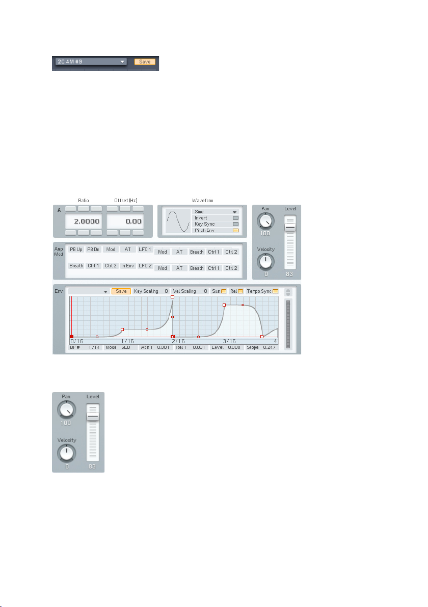
Templates
There is a handy Template system available for storing your fresh Algorithms
and for accessing the preset Algorithms that ship with your FM8.
The Template menu presents a list of preset algorithms, including all those
found in the original DX7. Save lets you store an Algorithm to the list of presets.
To save an Algorithm you created, enter a name in the name eld, click the
Save button and choose the Slot you want top save to. The maximum number
of stored Templates is 64.
4.11.2. Operator A-E Pages
Global Controls
Level serves as a master level control for all values in the matrix column
associated with the selected Operator, except for any feedback to itself.
Example: If Operator E modulates Operator F and sends its output to the
main output, there are two values in the column, one connecting to Operator E
74 – FM8
Page 75

and one to the output. Lowering or raising Level will lower or raise both values.
Similarly, raising or lowering the highest-value numerical will raise or lower
the slider.
Note: the Level slider will always assume the value of the column
numerical with the highest value. It also works ratiometrically. In other
words, if one value is at 50 and another is at 100, reducing the second
value from 100 to 50 doesn’t reduce the other value to 0, but to half
of its value, as 50 is half the value of 100.
Pan mirrors an Operator’s pan control in the algorithm creation matrix, and
edits the audio output’s placement in the stereo eld, from left to right.
Changing this control changes the corresponding value in the matrix; changing
the numerical similarly changes the slider.
Velocity sensitivity sets how the overall envelope amplitude responds to velocity.
At lower values, velocity has less effect. At higher values, velocity kicks the
envelope up higher. If the Operator is a carrier, higher-amplitude envelopes
increase the volume. If the Operator is a modulator, higher-amplitude envelopes
change the timbre by increasing the brightness. With negative values a higher
keyboard velocity will reduce the Operator level.
Frequency Controls
Frequency Ratio denes the mathematical relationship of the Operator
frequency compared to the fundamental frequency of the note being played.
1.0000 means the Operator is the same pitch as the fundamental, 2.000
sets the Operator to the second harmonic (1 octave higher), 3.000 is the
third harmonic (octave + fth), etc. 0.5000 is the sub-harmonic one octave
below the fundamental.
These values are edited by clicking on one of the digits and moving it up or
down. The arrows above and below each numerical allow incrementing (up
arrow) or decrementing (lower arrow) one value at a time.
When the Ratio is not an exact integer (e.g. 1.0030) then the Operator is
detuned and will “beat” against other Operators. The beat frequency rises if
the note pitch increases, and falls if the note pitch decreases.
FM8 – 75
Page 76

Frequency Offset applies a constant frequency offset (in Hz) to the Operator to
cause detuning and beating against other Operators. This is constant regardless
of pitch. Example: a 5 Hz Offset causes beating at exactly 5 Hz between the
selected Operator and another Operator with no offset.
When using an FM-Operator as a static wave shaper (Ratio = 0, Offset = 0),
the phase of the waveform can be adjusted. This makes a big difference to the
modulated sound. A negative value for Offset controls the phase in percent.
So Offset = -10 means the wave is shifted by 10%. Offset = -100 is 100%
shift which sounds the same as no shift at all, as the waveform is periodic.
Waveform Controls
An Operator can have any of 32 different waveforms (the original DX7 had
only sine waves). Clicking and dragging up or down on the numerical selects
the waveform.
Key Sync vs. Free Run
Clicking on this box toggles between these two selections. Key Sync mode
resets the oscillator phase at the beginning of each note. When any group of
Operators needs to have a xed phase relationship to preserve a particular
tone quality, activate Key Sync for all Operators in the group. With Free Run
mode, there is no phase reset.
Pitch Envelope toggles modulation by the pitch envelope on and off. This
allows some nice effects. When one carrier is pitched and another is not, a
deactivated Pitch Envelope for one of them gives a fat, time-varying detune
effect. When this time-varying detuning is applied between a carrier and its
modulator, the result is an inharmonic FM effect.
Inver tWaveform ips the waveform upside down. This can make a subtle
difference in FM-Modulation. The effect is especially noticeable when a
waveform Operator feeds back on itself.
76 – FM8
Page 77
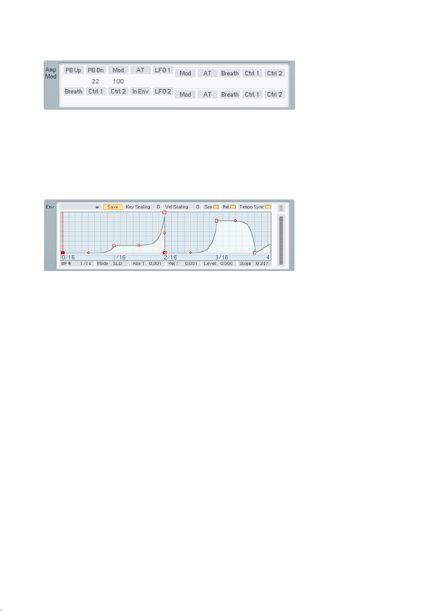
Amplitude Modulation Controls
This is a subset of the Modulation Matrix page. Please refer to chapter 4.11.7
for information on assigning controllers; the only difference is that to conserve
space, the pitch modulation sources are arranged in two lines stacked above
each other, instead of one long line.
Amplitude Envelope Controls
The lower pane displays the Amplitude Envelope varying the Operator amplitude
over time.
Key Scaling edits how keyboard pitch affects the envelope times. At higher
values, playing higher up on the keyboard shortens all time values. This
emulates many plucked instruments, whose notes attack and decay more
quickly at higher pitches.
Velocity Scaling edits how velocity affects the envelope times. At positive
values, hitting the keys harder shortens all time values. At negative values
the envelope times become longer with higher key velocity.
Sustain mode: In FM7, Sustain was always on. When Sustain is turned off,
the envelope does not go into a loop or wait at the loop-end marker, it just
continues straight into the release phase.
Release mode: In FM7, Release was always on. When Release is turned off,
Note-Off messages are ignored. So when a key is released, the envelope just
keeps doing whatever it’s doing: looping, sustaining or (with sustain off) running
through to the end. When Release is off and Sustain is on, the Envelope will
never reach its end, but sustain indenitely, until it is retriggered .
Tempo Sync superimposes a grid on the envelope display that corresponds
to rhythmic values, such as quarter notes, eighth notes, 16th notes, etc.
Breakpoints can be snapped to these points.
FM8 – 77
Page 78

The quantization value depends on the current zoom factor, as set by rightclicking on the envelope ruler and dragging. (When Tempo Sync is enabled,
the ruler markings will be calibrated in rhythmic values instead of seconds.) If
the incoming tempo information changes, the envelope times are re-computed
to match the current song tempo. Example: If the envelope loop is set to a 1
beat duration, it will remain 1 beat long as the tempo changes.
If an envelope has already been created, enabling Tempo Sync will not change
the existing breakpoints. However, you can edit an existing envelope by moving
the breakpoints so that they snap to the nearest quantization value.
Note: Not all VST host software supplies tempo information to plug-in
instruments, so this feature may not work with your host software.
The Level meter displays the current amplitude of the Operator (for the last
triggered voice). This is the combined effect of the envelope and any amplitude
modulation. The FM-Matrix connections do not affect the meter reading.
The Envelopes are of the time/level type. You specify the levels and add the
times that it takes to get from one level to the next. Levels are created by
inserting breakpoints along a line. Then you move the breakpoints up or down
to change levels, and left or right to change times.
Right-click (Mac: ctrl-click) wherever you want to insert a breakpoint. The rst
and the last breakpoints always move up and down together because they are
really one and the same. This is because the envelope always has to start from
the same level where it ends. In fact, to prevent annoying clicks, the envelope
always does this, even when it is retriggered before it has reached the end - it
starts the rst segment, the attack, from whatever level the envelope happens
to be at when it is triggered.
The left-most breakpoint is where the envelope starts. The next breakpoint to
the right sets the envelope’s maximum level; the rst two breakpoints therefore
create the envelope’s attack. The next breakpoint to the right species the
level to which the envelope will fall after passing through the attack phase
(decay).
This and the maximum breakpoint fall on two vertical red lines. These indicate
the segment where the envelope reaches the sustain level, marked by the
horizontal red line. On this level the envelope stays as long as the key is held
down.
If you insert one or more breakpoints between the red markers the sustain
segment becomes a loop. This means that this part will be repeated as long
as the note is sustained. You can create novel tremolo effects by changing
78 – FM8
Page 79

the positions of these breakpoints and this can even be used to created
sequences.
If there are more than 3 breakpoints the sustain or loop segment can be
shifted by moving the vertical red lines with the mouse. They snap to the next
breakpoint, except the start and the end point.
Upon releasing the key, the envelope continues with the segment after the
second red marker. In our example there is one more breakpoint after the
sustain, the nal end point.
Dragging the Slope Handle (small circle) between breakpoints changes the
line’s slope between the breakpoints from concave over linear to convex.
Now let’s investigate the envelope parameter strip below the envelope. Except
as noted, clicking on a numerical value and dragging up or down edits the
value; they also update automatically if you move the breakpoint.
• # shows two numbers. The rst eld is the index number of the
breakpoint or stage being edited. The second eld is the total number of
envelope breakpoints. This is for display only and cannot be edited.
• Mode has two options, SLD and FIX. In SLiDe mode, if you move a
breakpoint left or right, the envelope to the right of the breakpoint
moves as well to maintain the same times and levels past the breakpoint
being edited.
• In Fix mode, the total envelope time doesn’t change. Moving a breakpoint
to the right not only lengthens its distance compared to the breakpoint
to its left, but shortens the distance compared to the breakpoint at its
right.
• Abs Time shows the amount of time in seconds from the start of the
envelope to the breakpoint being edited.
• Rel Time shows the time between the current and the previous
breakpoint.
• Delta Time shows the amount of time in seconds from the breakpoint
being edited to the breakpoint at its immediate left.
• Level shows the breakpoint level referenced to the centre line.
• Slope shows the state of the line between breakpoints. 0.5 indicates a
straight line. 0.999 indicates a maximally convex curve. 0.001 indicates
a maximally concave curve.
FM8 – 79
Page 80
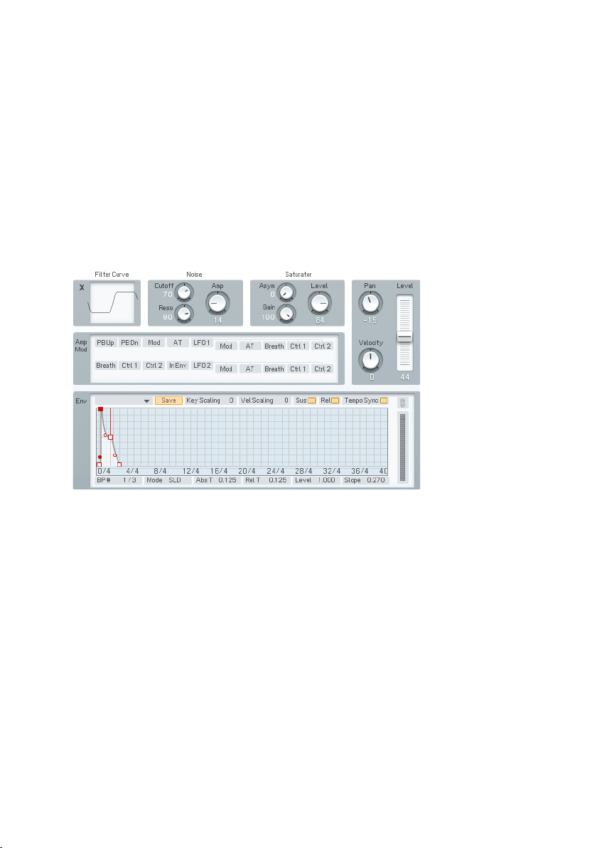
The ruler behind the envelope is calibrated in seconds. If the envelope extends
past the envelope’s visible range, click on the blue background and drag to
the left or right to see a different range of the ruler.
You can zoom in or out by clicking into the background and moving the mouse
up or down
Double-click on the background to have the envelope t exactly within the
visible part of the ruler.
To the right of the envelope there is a button indicating the link status of the
envelope. Note that it can only be used to unlink the current envelope.
4.11.3. Operator X Window
This special-case Operator resembles a conventional Operator in many ways:
its amplitude can be envelope-controlled, keyscaled, amplitude modulated,
and fed back to other Operators. However, it both generates noise and can
process an input signal with wave shaping (distortion). The noise is mixed
with the input signal, processed by a saturation stage and multiplied with
the envelope.
80 – FM8
Page 81
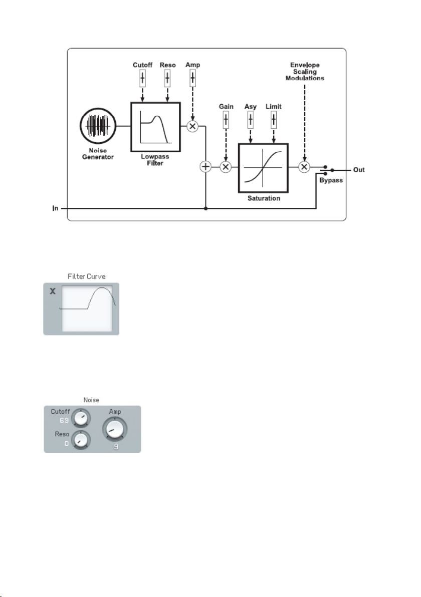
Operator X block diagram
Filter Curve
This display shows the effects on the waveform of manipulating the various
saturation controls. It has no adjustable parameters.
Noise and Saturator
Noise adds digitally-generated random noise (this is very useful for modulating
carriers, but also provides a useful audio output).
• Noise Amp sets the noise level.
• Noise Cutoff sets the noise generator’s lowpass lter cutoff. With very
low cutoff values, the noise source can serve as a low frequency random
modulator.
FM8 – 81
Page 82

• Noise Reso sets the noise generator’s lowpass lter resonance. It adds
a sense of pitch to the noise.
• Saturator Gain sets the level going through the Saturator. The higher
the level, the more pronounced the effects of the Asym and Limit
controls.
• Asym offsets the symmetry of the saturation. The higher the value, the
greater the saturation of negative amplitudes will be.
• Limit clips both the positive- and negative-going portions of the waveform.
Lower values produce more clipping; a value of 100 introduces no
clipping. Note: Extreme clipping will also lower the output level.
Amplitude Modulation Controls
This is a subset of the Modulation Matrix page. Please refer to chapter 4.11.7
for information on assigning controllers; the only difference is that to conserve
space, the pitch modulation sources are arranged in two lines stacked above
each other, instead of one long line.
Envelope
This is identical to the envelope function in the other Operators, as described
in this chapter under Operator Amplitude Envelope.
82 – FM8
Page 83
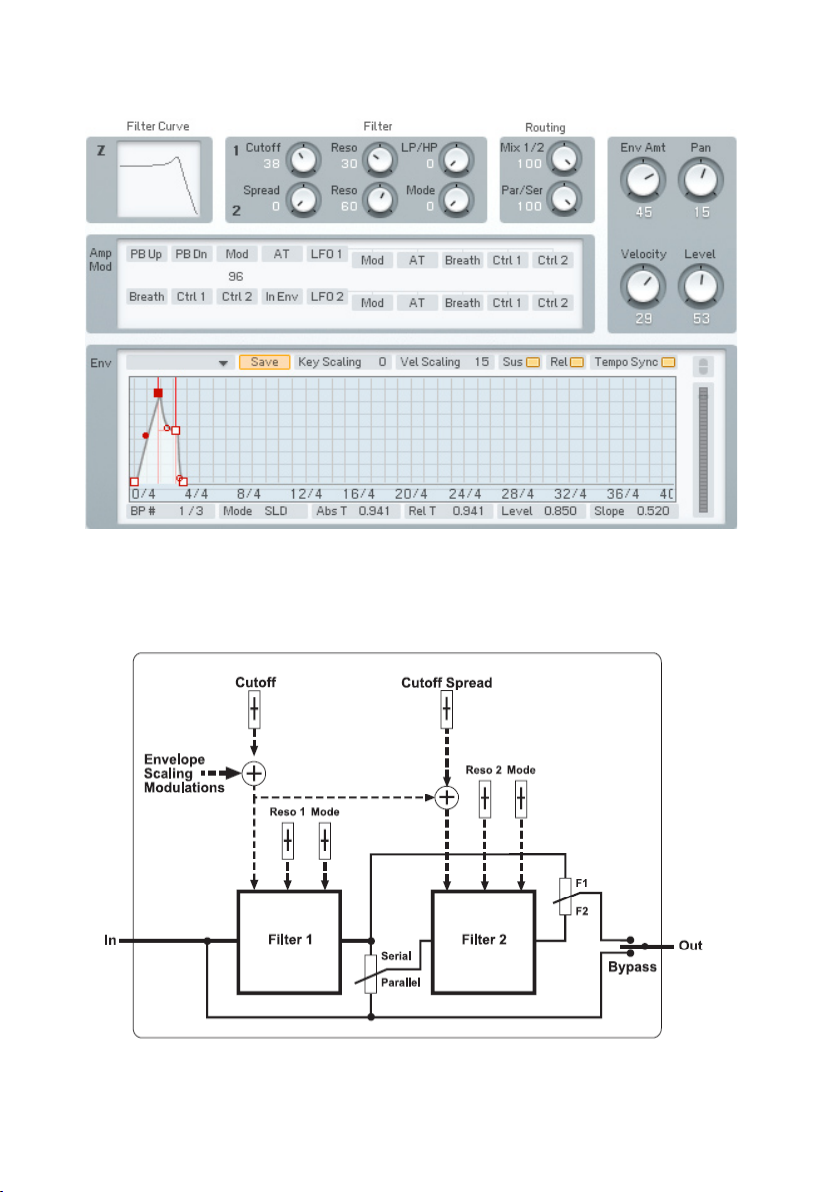
4.11.4. Operator Z Window
This special-case Operator is a signal processor that contains two separate
lters (each a 2-pole 24dB/oct multimode lter), which can be combined in
almost any imaginable conguration. Yes, FM synthesis nally has a greatsounding, analogue-style multimode lter.
Operator Z block diagram
FM8 – 83
Page 84
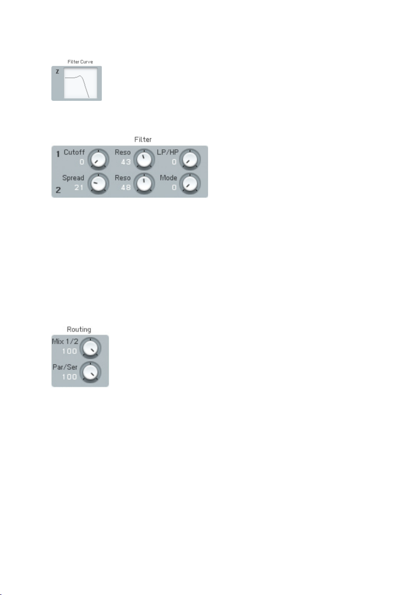
Filter
This display shows the effects on the waveform of manipulating the various
saturation controls. It has no adjustable parameters.
• Cutoff controls the initial cutoff frequency of both lters.
• Reso performs the same function for each lter, and sets the degree
of resonance (boost at the cutoff frequency).
• Mode performs the same function for each lter. It allows setting the
response mode in a continuously variable fashion from lowpass, to
bandpass, to highpass.
• Cutoff Spread applies to Filter 2 only. It offsets Filter 2’s frequency
compared to Filter 1. A value of 0 sets identical cutoffs for both lters.
Increasing the value increases Filter 2’s cutoff compared to Filter 1.
• Filter Mix changes the balance of the output of the two lters, from
only Filter 1 output, to both outputs, to only Filter 2 output.
• Par/Ser adjusts the conguration of the two lters from serial (Filter
2 follows Filter 1) to parallel (the same input signal feeds both lters,
and their outputs are mixed together), to anywhere in between.
84 – FM8
Page 85
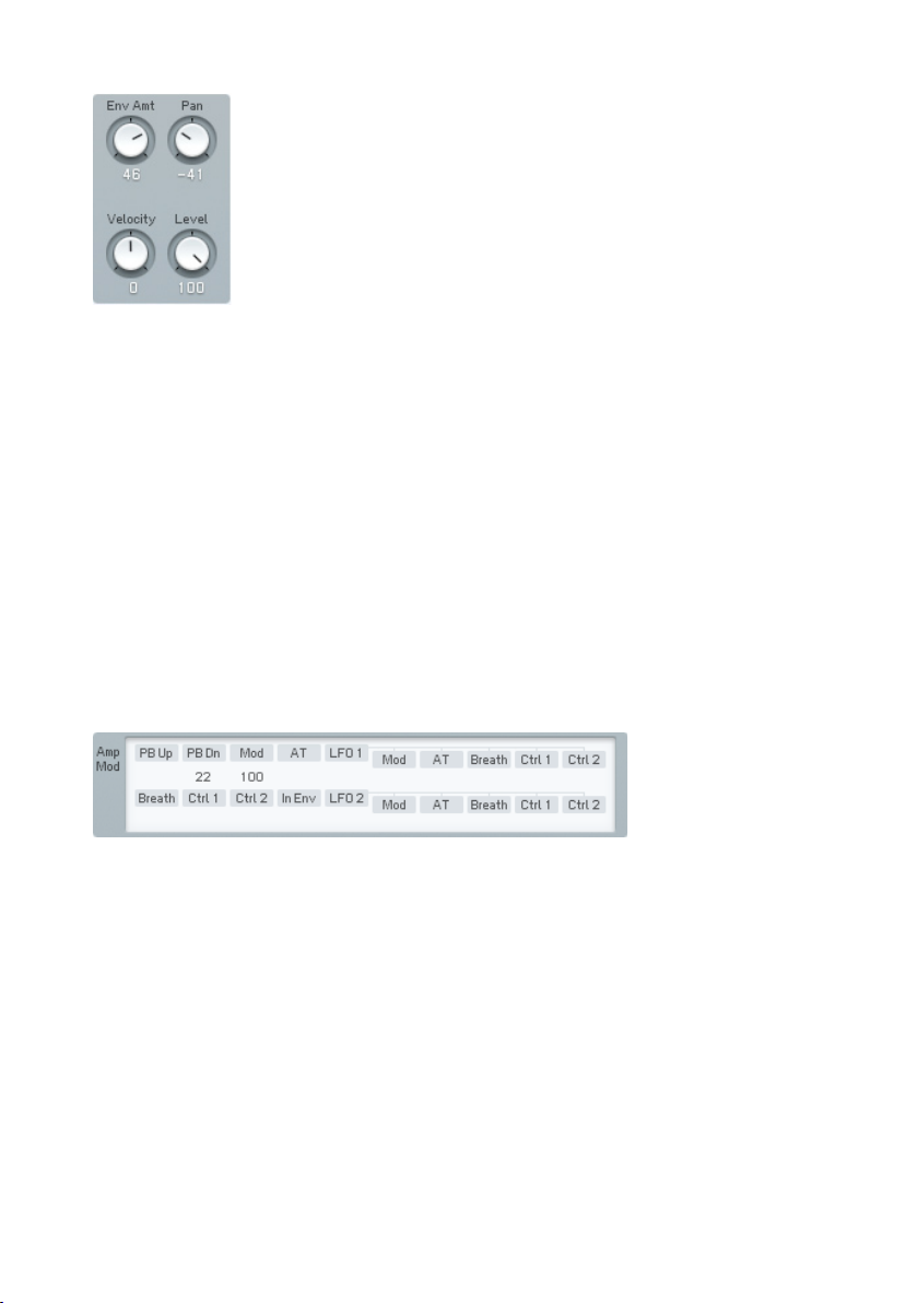
Note that the display of the lter response is invaluable in guring out how
these parameters affect the lter response.
• Env Amount determines how much the envelope affects the cutoff
frequency. Positive values kick the cutoff higher, while negative values
lower the cutoff.
• The Pan dial controls the placement of the Operator’s signal in the
stereo spectrum. Low values place it to the left, higher values to the
right.
• Use the Velocity knob to control the lter cutoff with velocity. The
modulation amount can be negative and positive.
• The Level dial determines the volume of Operator Z in the mix of all
Operators.
Cutoff Modulation Controls
This is a subset of the Modulation Matrix page. Please refer to chapter
4.11.7 for information on assigning controllers; the only difference is that
to conserve space, the pitch modulation sources are arranged in two lines
stacked above each other, instead of one long line. Also note that unlike the
other Operators, this modulation affects the lter cutoff frequency, not an
amplitude parameter.
Envelope
This functions similarly to the envelope function in the other Operators, as
described in this chapter under Operator Amplitude Envelope, but affects
lter cutoff rather than amplitude.
FM8 – 85
Page 86
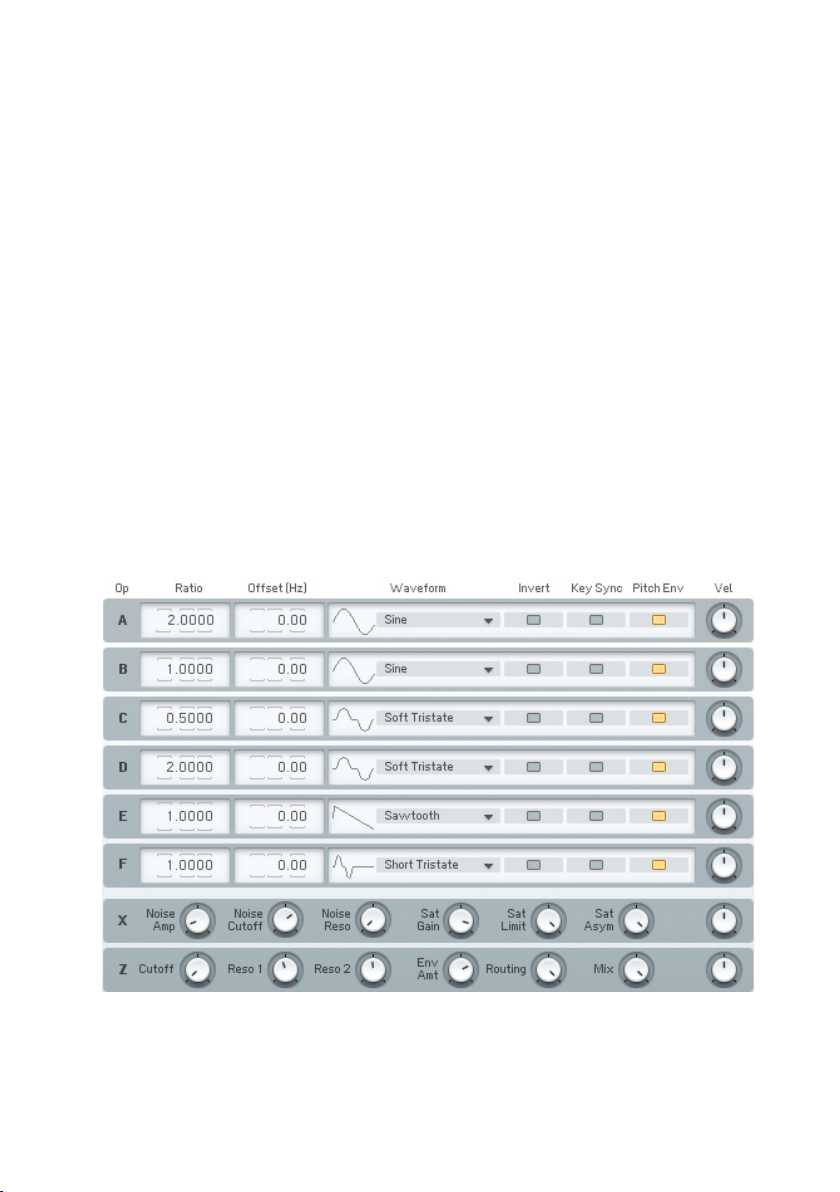
Application Notes
A typical use of Operator Z would be to put the lters in series and select
low pass mode for both. This provides the typical 24dB/octave low pass lter
response as found in traditional analogue synthesizer lters, such as the
Minimoog. To emulate the Oberheim lter sound, use only one lter, as these
lters had a 12 dB/octave response. These congurations are particularly
effective when sweeping the lter with the envelope.
Another option is to put the lters in parallel, choose bandpass mode with
relatively high resonance, and spread them a bit to simulate formants, such as
vocal formants (this usually doesn’t require cutoff frequency modulation).
Typically, the signal produced by the waveform Operators feeds through
Operator Z to make it softer and warmer (possibly just after passing through
the Operator X).
Of course, with the FM Matrix, Operator Z can connect anywhere between
the other Operators. When Z is connected to the output, it is actually a stereo
lter. This means that operators that play through the lter can be positioned
in the stereo panorama and will stay that way as they go through the lter.
4.11.5. Operators Window
This page gives you a one-stop overview of the most important Operator
parameters in a single window. Use it to conveniently see and manipulate all
86 – FM8
Page 87

frequency relations between Operators. You basically get an excerpt of the
controls of the main Operator pages without modulation and envelopes.
Frequency Controls
Frequency Ratio denes the mathematical relationship of the Operator
frequency compared to the fundamental frequency of the note being played.
1.0000 means the Operator is the same pitch as the fundamental, 2.000
sets the Operator to the second harmonic (1 octave higher), 3.000 is the
third harmonic (octave + fth), etc. 0.5000 is the subharmonic one octave
below the fundamental.
These values are edited by clicking on one of the digits and moving it up or
down. The arrows above and below each numerical allow incrementing (up
arrow) or decrementing (lower arrow) one value at a time.
When the Ratio is not an exact integer (e.g. 1.0030) then the Operator is
detuned and will “beat” against other Operators. The beat frequency rises if
the note pitch increases, and falls if the note pitch decreases.
Frequency Offset applies a constant frequency offset (in Hz) to the Operator to
cause detuning and beating against other Operators. This is constant regardless
of pitch. Example: a 5 Hz Offset causes beating at exactly 5 Hz between the
selected Operator and another Operator with no offset.
Waveform Controls
An Operator can have any of 32 different waveforms (the original DX7 had
only sine waves). Clicking and dragging up or down on the numerical selects
the waveform.
Key Sync vs. Free Run
Clicking on this box toggles between these two selections. Key Sync mode
resets the oscillator phase at the beginning of each note. When any group of
Operators needs to have a xed phase relationship to preserve a particular
tone quality, activate Key Sync for all Operators in the group. With Free Run
mode, there is no phase reset.
FM8 – 87
Page 88

• Pitch Envelope toggles modulation by the pitch envelope on and off.
• Invert inverts the waveform which can make a difference in sound when
used as a modulator.
• Velocity sensitivity sets how the overall envelope amplitude responds
to velocity. At lower values, velocity has less effect. At higher values,
velocity kicks the envelope up higher. If the Operator is a carrier,
higher-amplitude envelopes increase the volume. If the Operator is a
modulator, higher-amplitude envelopes change the timbre by increasing
the brightness.
Please have a look at the chapters about Operator X and Operator Z for
documentation of their parameters.
4.11.6. Envelopes Window
Equivalent in approach to the Operators Window, the Envelope Window shows
all Amplitude envelopes for all Operators on one page in a list of graphs for
easy editing.
One of them is displayed in edit view. You can choose the envelope you want
to edit by clicking on the respective Operator letter to the left.
The FM Matrix to the right can be hidden by clicking on the Expand button,
providing more space and better overview for editing operations.
The Link buttons to the right of the graphs allow for editing several envelopes
at the same time. The envelope you link others to is always the one currently
chosen for edits. Click on the Link buttons of other envelopes to build a Link
Group. If you now edit any of the linked envelopes, the other envelopes of the
Link Group will look exactly the same as the one you changed.
88 – FM8
Page 89

You can even build several Link Groups in parallel. If you already have a Link
Group active and add an envelope of this old group to a new group, it will lose
its connection to the rst group and become a member of the new one.
4.11.7. Modulations Windows
Although each Operator page shows modulation information for that individual
Operator, this page shows the modulation parameters for all Operators in one
convenient screen.
Modulation Basics
The amplitude of each Operator has a major effect on the overall sound.
Therefore, many modulation sources are available to vary the Operator
amplitude in real time.
Modulations are set up on a matrix, with columns of modulation sources and
rows of modulation targets (destinations). At each junction, you can vary the
amount of modulation going to the destination.
If you want to add a modulation:
• Imagine a line going downward from the modulation source.
• Imagine a second line going across to the modulation target.
• Click and hold at the junction represented by a blue eld in the
background.
• Drag up. The imaginary lines are now drawn in, and a box appears
with a numerical value. Drag until the numerical shows the desired
modulation level.
Removing a Modulation Control:
Click on the numerical box, and drag down. Upon reaching 0, the box and
lines disappear.
FM8 – 89
Page 90
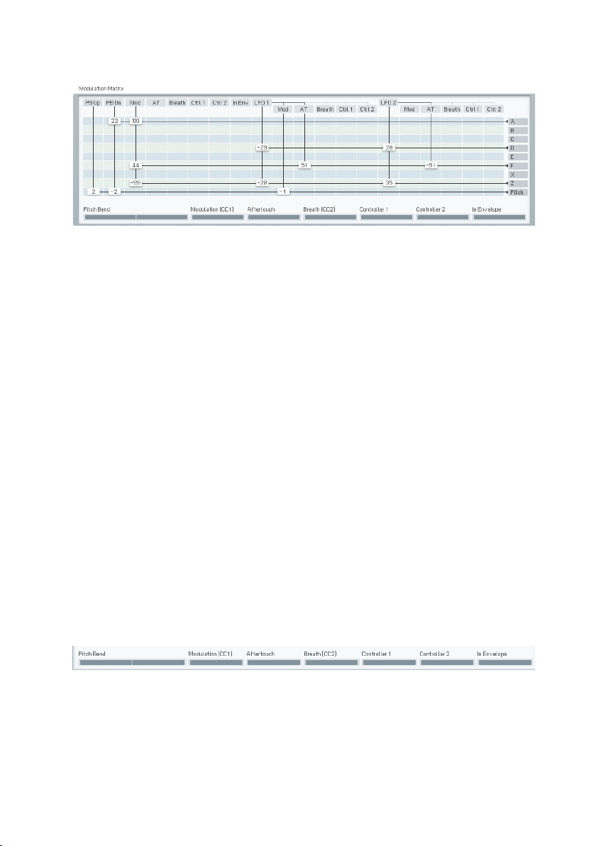
Modulation Matrix
This shows all modulation sources and targets. Available modulation sources
(left to right) are:
• PB Up Pitch bend up range
• PB Dn Pitch bend down range, applied in negative direction
• Mod Modulation wheel (MIDI controller #1)
• AT Aftertouch (channel pressure)
• Breath Breath controller (MIDI controller #2)
• Ctrl 1 1st MIDI controller assigned on Master Page
• Ctrl 2 2nd MIDI controller assigned on Master Page
• In Env Envelope derived from input signal amplitude
The parameters for LFO1 and LFO2 are identical, so we will list those only
for LFO1.
• LFO 1 Main LFO output
• LFO 1 Mod LFO1 output controlled by mod wheel
• LFO 1 AT LFO1 output controlled by aftertouch
• LFO 1 Breath LFO1 output controlled by breath controller
• LFO 1 Ctrl 1 LFO1 output controlled by the 1st MIDI controller assigned
on the Master page
• LFO 1 Ctrl 2 LFO1 output controlled by the 2nd MIDI controller assigned
on the Master page
The lower strip of controls provides two independent functions: modulation
input monitoring, and modulation input control by mouse. These are available
for the following modulation sources:
90 – FM8
Page 91
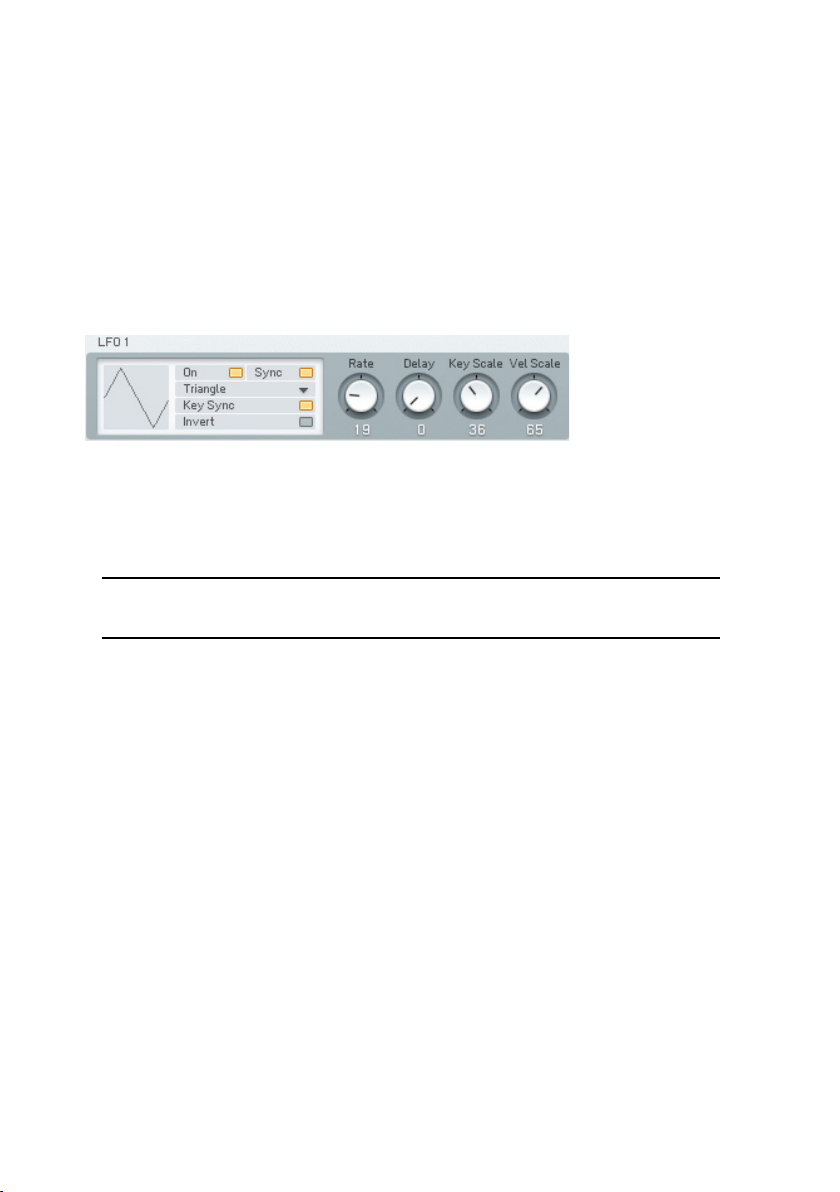
Pitch Bend, Modulation, Breath, Controller 1 (assigned on Master page), and
Controller 2 (assigned on the Master page). Input Envelope has only the meter,
and does not include the control function.
• The meters display the incoming control signals.
• The numerical not only works as a display but also allows entering the
value by mouse action (click on it and drag up or down to change).
• A double-click on the individual displays restores them to zero.
LFO 1 and 2 Controls
The two LFOs are identical, so we will describe only LFO1.
On/Off enables/disables the LFO.
Tempo Sync matches the LFO frequency to the song tempo and syncs the LFO
to the beat. When disabled, the LFO ignores the song tempo.
Note: Not all VST host software supplies tempo information to plug-in
instruments, so this feature may not work with your host software.
• Waveform chooses among the various modulation waveforms. The
waveforms are the same as available for the FM Operators. Click in the
numerical and drag up or down to select the desired waveform.
• Invert sets the polarity of the waveform. If inactive, the LFO produces
positive values, while active Invert produces negative values.
• With inactive Key Sync, the LFO waveform runs continuously. When you
press a key, the modulation picks up whatever part of the LFO curve
is happening at that moment. With active Key Sync, pressing a key
resets the LFO to the beginning of the waveform. Example: Suppose
Sine is selected as the waveform. With Key Sync, upon pressing a
key, the waveform starts at 0 and goes positive. Without KeySync, the
waveform could start anywhere: at 0, at the peak, at the lowest value,
somewhere in between, etc.
• Invert ips the waveform upside down. This is useful in Tempo Sync
mode, to make the modulation go down instead of up, on the beat.
FM8 – 91
Page 92

• Rate sets the LFO’s base frequency.
• Delay sets the time the LFO’s start will be delayed after the note’s
start.
• Key Scale changes the LFO’s rate as you play over the keyboard. Higher
values cause the rate to speed up as you play progressively higher on
the keyboard.
• Velocity Scale changes the LFO’s rate according to velocity. With higher
values, higher velocities increase the LFO rate.
4.11.8. Key Scaling Window
Keyscaling Graphs
Keyscaling sets how the Operator amplitude changes across the keyboard
range. Choose the Operator by clicking on the Operator letter to the left of
the stack of keyscaling graphs.
Like the envelopes, you can create/delete breakpoints to create a particular
curve shape. Dragging the small circle between the breakpoints changes
the line’s shape from concave, to straight, to convex. A small keyboard
graphic below the curve serves as a reference for breakpoints. The white
area corresponds to the range of the FM8 keyboard, or a standard 5-octave
MIDI keyboard controller.
The default keyscale line is at 0 (maximum level), as indicated by a horizontal
line going across the top of the graph. You reduce the level for a particular
area of the keyboard by lowering the line over a particular keyboard range. In
the screen shot above, amplitude falls off starting at around middle C, and
the slope gets progressively steeper the higher you play on the keyboard.
92 – FM8
Page 93
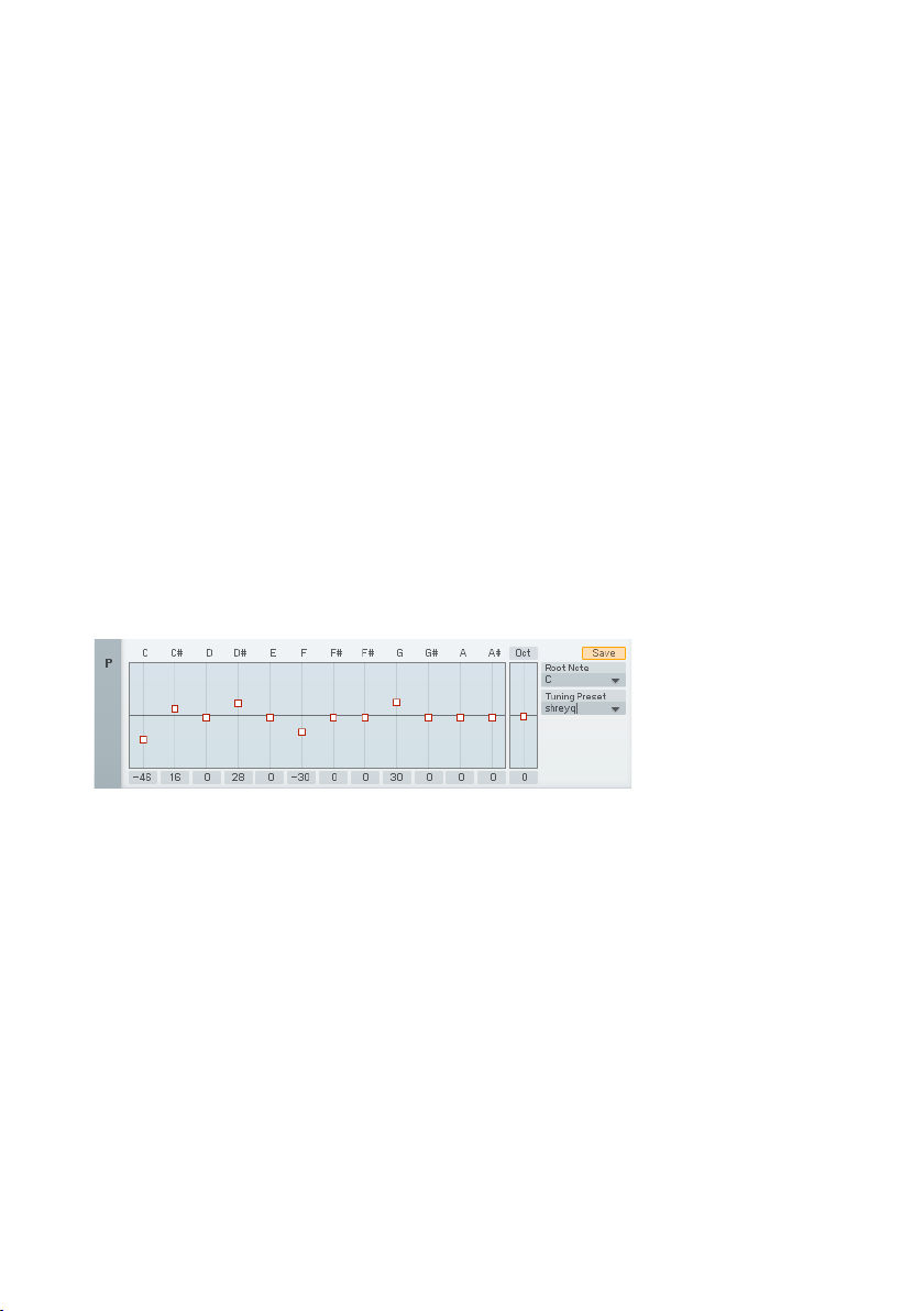
Here’s what the various parameters indicate.
Note shows the MIDI note number of any breakpoint on which you click, or
when you create a breakpoint. Moving the breakpoint updates the MIDI note
number.
• Level shows the level of any breakpoint on which you click, or when you
create a breakpoint. Moving the breakpoint updates the level. Levels
are referenced to 0, so the more negative the number, the lower the
level.
• Slope shows the state of the line between breakpoints. 0.5 indicates a
straight line. 1.000 indicates a maximally convex curve. 0.000 indicates
a maximally concave curve.
Microtuning Controls
Even-tempered tuning, which divides an octave into 12 equal intervals, was
developed for playing in different key signatures. However there are many
other scales, such as just intonation, microtunings, stretch tunings so that
pianos sound more in tune, etc. Several of these are available in the FM8 as
presets, or you can create your own tunings using the microtuning controls
on the Keyscaling page.
Each of the twelve semitones that make up an octave (C, C#, D, etc.) has an
offset control that can change the note’s tuning by - 99 cents to +100 cents.
Zero offset gives a standard even-tempered scale. Any offsets are preserved
throughout all octaves (example: if D is offset by +3 cents, all D notes will
be offset by +3 cents).
The Octave stretch parameter leaves middle C unaffected, but positive offset
values create progressively sharper note tunings when playing higher up on
the keyboard, and progressively atter note tunings when playing lower on
the keyboard. A negative offset value does the reverse - higher notes become
progressively atter, while lower notes become progressively sharper.
An offset of 50 compresses the scale into two semitones per key, or two
octaves into one octave. An offset of -50 does the opposite, expanding the
normal scale into a quarter tone scale (in other words, there are 24 notes
per octave).
FM8 – 93
Page 94

Pianos use stretch tuning, which can be simulated in the FM8 by a small
positive offset. This is because the harmonics of lower strings are slightly sharp,
as the strings cannot be as long as the laws of physics would like, because
of a piano’s size constraints. Therefore, tuning them slightly at allows the
harmonics to fall into tune with the rest of the piano. A related phenomenon
occurs at the high end, where notes have to be tuned slightly sharp to sound
in tune with harmonics from lower strings.
With small offset values (near 0), the number is an octave’s detuning in cents.
Example: a reading of +5 means that each octave is 5 cents sharp.
To select a Microtuning preset click on the arrow in the right edge of the name
eld and choose a preset from the drop down list. To save a tuning preset you
created, enter a name in the name eld and click on Store.
With the Root note control you can set a note to be the root of the displayed
scale.
The Microtuning controls also sport a Template system. Find the factory
templates and your own, previously stored patterns by clicking on the small
triangle of the menu. There can be up to 64 stored Templates.
If you have developed a nice new tuning, you can give it a new name with a
single-click into the name eld and subsequent keyboard entry.
For saving the new tuning, use the Store command. A click on this button
opens the list of Templates. Click on the desired slot and the new tuning is
stored. Please be aware, that the Template already residing in the chosen
slot will be overwritten.
94 – FM8
Page 95
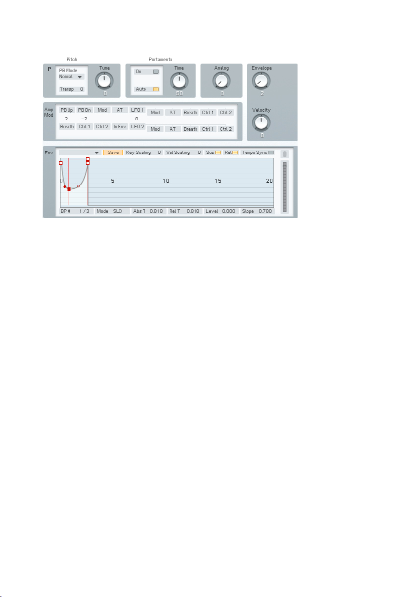
4.11.9. Pitch Window
On the Pitch page you nd various controls dealing with – well – static and
dynamic pitch.
Basic Pitch
The top row of controls starts with the Pitch Bend Mode. You get a choice of
ve:
• Normal affects all notes equally.
• Highest affects only the highest note if several notes are held. This is
designed to provide guitar-like pitch bending effects.
• Lowest affects only the lowest note if several notes are held.
• Key On allows pitch bend to work only as long as a key is held down.
There is no bend during the sound’s release phase.
• Latest affects only the note that was played last.
Use the Transpose dial to shift the main pitch of the sound up or down for
up to 24 semitones.
Tune is for ne tuning your sound in cents. You get a range from -99 to +100
cents.
FM8 – 95
Page 96
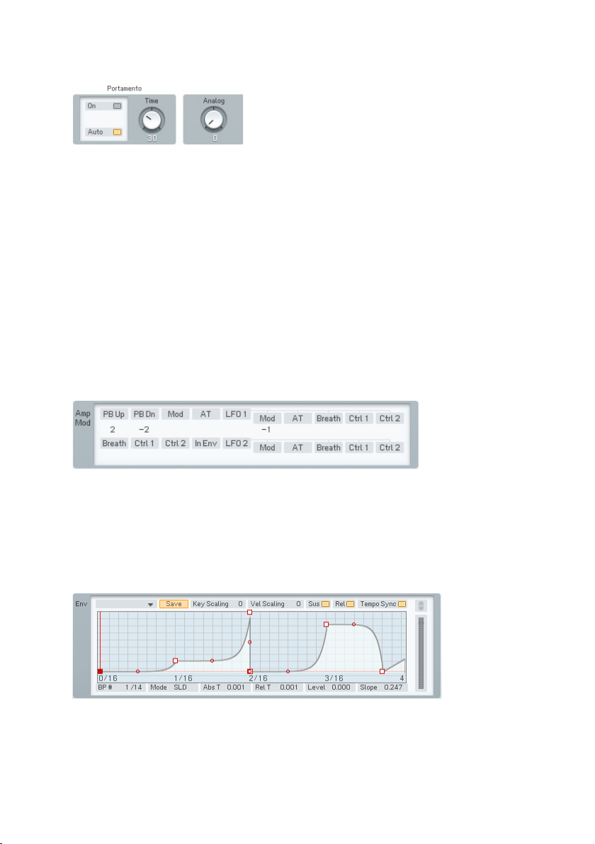
Portamento and Analog
Portamento On/Off enables or disables the portamento function.
• Portamento Auto allows portamento only for legato notes played without
gaps in between. If you release a key before playing the next one, there
will be no portamento.
• Portamento Time controls how long it takes for the pitch to glide from
one note to another. 0 = shortest time, 100 = longest time.
• The Analog Dial is mirrored from the Master page. It introduces random
variations between voices. This used to happen with analogue gear
– e.g. component values would change as temperatures drifted, and
so on. Higher values increase the degree of randomness, and are very
effective in Unison mode.
Pitch Modulation
This is a subset of the Modulation Matrix page. Please refer to that chapter
for information on assigning controllers; the only difference is that to conserve
space, the pitch modulation sources are arranged in two lines stacked above
each other, instead of one long line.
Pitch Envelope
The lower pane displays the Pitch envelope. The pitch envelope varies the pitch
over time. Remember that you can decide for every Operator if it is modulated
96 – FM8
Page 97

by the Pitch Envelope. You nd the related control on the Operators window
and on the dedicated Pages for the individual Operators.
Key Scaling edits how keyboard pitch affects the envelope times. At higher
values, playing higher up on the keyboard shortens all time values. This
emulates many plucked instruments, whose notes attack and decay more
quickly at higher pitches.
Velocity Scaling edits how velocity affects the envelope times. At positive
values, hitting the keys harder shortens all time values. At negative values
the envelope times become longer with higher key velocity.
With Sustain switched off, the envelope will always run to the end, no matter
whether you hold the key or not. With Sustain active, the envelope behaves
like your standard synth-envelope by staying on the Sustain level or playing
the loop until the key is released.
A deactivated Release button leads to an envelope that ignores the Note Off
signal. This means it either stays on the Sustain level or plays the loop forever,
respectively, when Sustain is on, or it runs one single time to the end (one shot)
when Sustain is off. With active Release the envelope behaves normally.
Tempo Sync superimposes a grid on the envelope display that corresponds
to rhythmic values, such as quarter notes, eighth notes, 16th notes, etc.
Breakpoints can be snapped to these points.
The quantization value depends on the current zoom factor, as set by rightclicking on the envelope ruler and dragging. (When Tempo Sync is enabled,
the ruler markings will be calibrated in rhythmic values instead of seconds.) If
the incoming tempo information changes, the envelope times are re-computed
to match the current song tempo. Example: If the envelope loop is set to a 1
beat duration, it will remain 1 beat long as the tempo changes.
If an envelope has already been created, enabling Tempo Sync will not change
the existing breakpoints. However, you can edit an existing envelope by moving
the breakpoints so that they snap to the nearest quantization value.
Note: Not all VST host software supplies tempo information to plug-in
instruments, so this feature may not work with your host software.
The Envelopes are of the time/level type, where you specify levels and the
times that it takes to get from one level to the next. Levels are specied by
inserting breakpoints along a line, then moving the breakpoints up or down
to change levels, and left or right to change times.
Right-click (Mac: ctrl-click) wherever you want a breakpoint. The rst and
FM8 – 97
Page 98

last breakpoints move up and down together, because it is assumed you will
eventually want the envelope to end up where it started.
The left-most breakpoint is where the envelope starts. The next breakpoint to
the right sets the envelope’s maximum level; the rst two breakpoints therefore
create the envelope’s attack. The next breakpoint to the right species the
level to which the envelope will fall after passing through the attack phase
(decay).
This and the maximum breakpoint fall on two vertical red lines. These indicate
the segment where the envelope reaches the “sustain” level, marked by the
horizontal red line. On this level the envelope stays as long as the key is held
down.
If you insert one or more breakpoints between the red markers the “sustain”
segment becomes a “loop”. This means that this part will be repeated as long
as the note is sustained. You can create novel tremolo effects by changing
the positions of these breakpoints.
If there are more than 3 breakpoints the sustain or loop segment can be
shifted by moving the vertical red lines with the mouse. They snap to the next
breakpoint, except the start and the end point.
Upon releasing the key, the envelope continues with the segment after the
second red marker. In our example there is one more breakpoint after the
sustain, the nal end point.
Dragging the small circle between breakpoints can change the line’s shape
between the breakpoints from concave, to straight, to convex.
Now let’s investigate the envelope parameter strip below the envelope. Except
as noted, clicking on a numerical value and dragging up or down edits the
value; they also update automatically if you move the breakpoint.
• # shows two numbers. The rst eld is the index number of the
breakpoint or stage being edited. The second eld is the total number of
envelope breakpoints. This is for display only and cannot be edited.
• Mode has two options, SLD and FIX. In SLiDe mode, if you move a
breakpoint left or right, the envelope to the right of the breakpoint
moves as well to maintain the same times and levels past the breakpoint
being edited.
• In Fix mode, the total envelope time doesn’t change. Moving a breakpoint
to the right not only lengthens its distance compared to the breakpoint
to its left, but shortens the distance compared to the breakpoint at its
right.
98 – FM8
Page 99
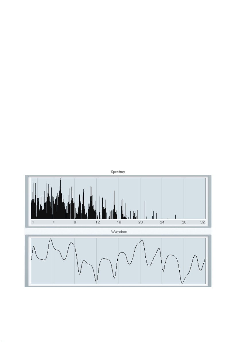
• Abs Time shows the amount of time in seconds from the start of the
envelope to the breakpoint being edited.
• Rel Time shows the time between the current and the previous
breakpoint.
• Delta Time shows the amount of time in seconds from the breakpoint
being edited to the breakpoint at its immediate left.
• Level shows the breakpoint level referenced to the centre line.
• Slope shows the state of the line between breakpoints. 0.5 indicates a
straight line. 0.999 indicates a maximally convex curve. 0.001 indicates
a maximally concave curve.
The ruler behind the envelope is calibrated in seconds. If the envelope extends
past the envelope’s visible range, click on the blue background and drag to
the left or right to see a different range of the ruler.
You can zoom in or out by clicking into the background and moving the mouse
up or down
Double-click on the background to have the envelope t exactly within the
visible part of the ruler.
4.11.10. Spec Window
The two displays are non-editable and for reference purposes only.
FM8 – 99
Page 100

The upper graph is the Spectrum of your sound. It displays the frequency
distribution. This can be very useful for analysing frequency content relative
to parameter changes while editing a sound.
The second graph shows your sound in the time domain, displaying the
waveform.
4.12. Browser and Attributes Window
4.12.1. Attribute Concept
FM8 provides a new and musical way to save, browse and load its sounds. The
old paradigm of sounds within different sound banks is left behind with all its
organizational problems. Instead, each Sound is saved into a single le that
can then easily be ported between platforms or projects. Those sound les can
also be loaded directly by Native Instruments’ KORE. Therefore, each sound
within FM8 is called a KoreSound. If you are familiar with KORE’s powerful
approach, the following explanations will be rather easy to understand.
To handle all those single KoreSound les you need a powerful way to browse
them. Therefore, each KoreSound le also contains information about the sound
in musical terms, called the sound’s Attributes. The Attributes Window of FM8
provides a list of about 170 attributes. By combining them individually each of
the synthesizer’s sounds can be described due to its origin or source, its timbre,
articulation or genre. If FM8 is used as an effect, the sound can be tagged
with a different, dedicated set of attributes. You can also enter additional
Meta Information like the sound’s author or its number of outputs.
All KoreSound les placed in FM8’s user and factory library folders – read
more about this preference in chapter 4.4.1 - are automatically integrated into
a Database. The Browser Window of FM8 is your interface to this database.
Within the Browser you can combine the attributes to nd a sound that ts
your needs. For instance, you can activate the attributes Bass, Digital, Dark
and Fat, Monophonic and Techno/Electro to nd exactly that – a digitally cold
yet pushing and fat bass line sound. Different bank les at various locations
on your disk won’t bother you anymore – you’ll nd the KoreSounds you need
for your music fast.
Please note that there is a differentiation between SingleSounds and
MultiSounds within KORE. All KoreSounds you save with FM8 will be
loaded as SingleSounds in KORE, and the FM8 will also only be able
to load SingleSounds. Please refer to the KORE manual for detailed
information. This difference is of no importance within FM8 itself.
100 – FM8
 Loading...