

Page 1

NAD
SER VICE MANUAL
C 541
COMPACT
DISC PLAYER
C 541
COMPACT
DISC PLAYER
Page 2
2
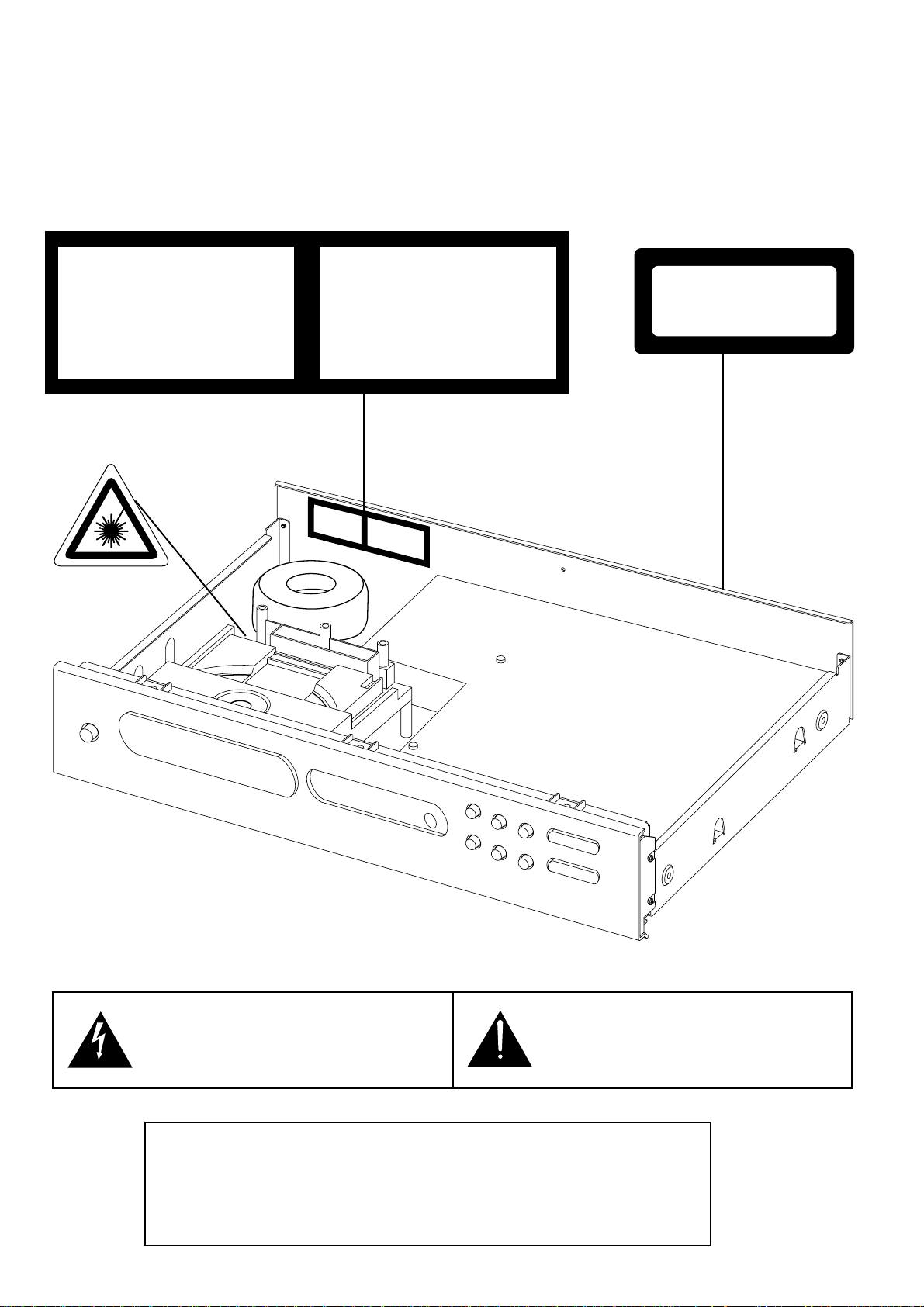
SAFETY INFORMATION
CAUTION
CAUTION
- INVISIBLE LASER RADIATION WHEN OPEN AND
INTERLOCKS DEFEA TED. AVOID EXPOSURE TO BEAM.
ADVARSEL
- USYNLIG LASERSTRÅLING NÅR DEKSEL ÅPNES OG
SIKKERHEDSLÅS BRYTES. UNNGÅ EKSPONERING FOR STRÅLEN.
ADVARSEL
- USYNLIG LASERSTRÅLING VED ÅBNING, NÅR
SIKKERHEDSAFBRYDERE ER UDE AF FUNKTION. UNDGÅ
UDSÆTTELSE FOR STRÅLING.
VARING
- OSYNLING LASERSTRÅLNING NÄR DENNA DELÄR
ÖPPNAD OCH SPÄRRAR ÄR URKOPPLADE. STRÅLEN ÄR FARLIG.
VARO!
- AVATTAESSAJASUOJALUKITUS OHITETTAESSA OLET
ALTTIINANÄKTMÄTÖNTÄ LASERSÄTEILYLLE. ÄLÄ KAISO
SÄTEESEEN.
VORSICT!
- UNSICHTBARE LASERSTRAHLUNG TRITTAUS, WENN
DECKEL GEÖFFNET UND WENN SICHERHEITSVERRIEGELUNG
ÜBERBRÜCKT IST. NICHTDEM STRAHLAUSSETZEN.
THIS DEVICE COMPLIES WITH PART 15 OF THE FCC RULES.
OPERATION IS SUBJECTTO THE FOLLOWING TWO CONDITIONS:(1) THIS DEVICE MAY NOT CAUSE HARMFUL INTERFERENCE, AND
(2) THIS DEVICE MUST ACCEPT ANY INTERFERENCE RECEIVED,
INCLUDING INTERFERENCE THAT MAY CAUSE UNDESIRED
OPERATION.
CATUION
ADVARSEL
KBVNCLKNBCVLKNLKNVLKNCVNCLVK JK
ADVARSEL
HFKLJHJLDKLJLKDJLKFHJHSGMMKJHGSJK
HGKJDHSGKJHGSJK
HGKJDHSGKJHGS
VARING
KLHKFG;LKNG;LKJGF;LKJGF;LKJFL;SJK
HGKLFH;L;HJMNMD
HGKJDHSGKJHGKLGDJH
VARO!
KBVNCLKNBCVLKNLKNVLKNCVNCLVK JK
HGKJDHSGKJHJBJKBKJBJKGS
VORSICT!
JHFKLJHJLDKLJLKDJLKFHJHSGKJHGSJK
HGKLFH;L;HHBHHJD
CLASS 1
LASER PRODUCT
The lightning flash with arrowhead, within an equilateral tri-
angle is intended to alert the user of the presence of
uninsulated "dangerous voltage" within the product’s
enclosure; that may be of sufficient magnitude to consti-
tute a risk of electric shock to persons.
The exclamation point within an equilateral triangle is intend-
ed to alert the user of the presence of important operating
and maintenance (servicing) instructions in the literature
accompanying the appliance.
Page 3

3
SERVICE SAFETY PRECAUTIONS
1. Replacing the fuses
CAUTION: FOR CONTINUED PROTECTION AGAINST THE RISK OF FIRE REPLACE ONLY
WITH SAME TYPE OF FUSE.
Reference No Part Number Description
M507 *AH 5120-0052-0 FUSE T1.6A 250V 5X20MM
M512, M513 *AH 5120-0020-0 FU T1A250V UL/CSA 5X20
M514 *AH 5120-0026-0 FU T315MA L 250V UL/CSA
M507 *C 5120-0050-0 FUSE T1.6A 250V 5X20MM
M512, M513 *C 5120-0018-0 FU T1A 250V SEMKO/VDE
M514 *C 5120-0027-0 FU T315MAL 250V
NOTE:
<*AH > : USA, CANADIAN MODEL ONLY.
<*C > : EUROPEAN MODEL ONLY.
2. Safety check out
(Only U.S.A. model)
Before returning the product to the customer, make leakage current or resistance measurements
to determine that exposed parts are acceptably insulated from the supply circuit.
Parts marked with the symbol are critical with regard to the risk of fire and electric shock.
Replace only with parts recommended by the manufacturer.
CONTENTS
DESCRIPTION PAGE
SPECIFICATIONS . . . . . . . . . . . . . . . . . . . . . . . . . . . . . . . . . . . . . . . . . . . . . . . . . . . . . . . . . . .4
REAR PANEL / FRONT PANEL . . . . . . . . . . . . . . . . . . . . . . . . . . . . . . . . . . . . . . . . . . . . . . . . .5
DISASSEMBLY INSTRUCTIONS . . . . . . . . . . . . . . . . . . . . . . . . . . . . . . . . . . . . . . . . . . . . . . . .6
BLOCK DIAGRAM . . . . . . . . . . . . . . . . . . . . . . . . . . . . . . . . . . . . . . . . . . . . . . . . . . . . . . . . . . .7
WIRING DIAGRAM . . . . . . . . . . . . . . . . . . . . . . . . . . . . . . . . . . . . . . . . . . . . . . . . . . . . . . . . . .8
RF PATTERN TESTING . . . . . . . . . . . . . . . . . . . . . . . . . . . . . . . . . . . . . . . . . . . . . . . . . . . . . . .9
IMPORTANT NOTES . . . . . . . . . . . . . . . . . . . . . . . . . . . . . . . . . . . . . . . . . . . . . . . . . . . . .10-11
PCB LAYOUT . . . . . . . . . . . . . . . . . . . . . . . . . . . . . . . . . . . . . . . . . . . . . . . . . . . . . . . . . . .12-14
SCHEMATIC DIAGRAM . . . . . . . . . . . . . . . . . . . . . . . . . . . . . . . . . . . . . . . . . . . . . . . . . . .15-16
IC BLOCK DIAGRAM . . . . . . . . . . . . . . . . . . . . . . . . . . . . . . . . . . . . . . . . . . . . . . . . . . . . .17-19
TROUBLESHOOTING GUIDE . . . . . . . . . . . . . . . . . . . . . . . . . . . . . . . . . . . . . . . . . . . . . . . . .20
ELECTRICAL PARTS LIST . . . . . . . . . . . . . . . . . . . . . . . . . . . . . . . . . . . . . . . . . . . . . . . . .21-26
MECHANISM EXPLODED VIEW . . . . . . . . . . . . . . . . . . . . . . . . . . . . . . . . . . . . . . . . . . . . . . .27
MECHANISM EXPLODED VIEW PARTS LIST . . . . . . . . . . . . . . . . . . . . . . . . . . . . . . . . . . . . .28
EXPLODED VIEW OF LASER CD11CA-G . . . . . . . . . . . . . . . . . . . . . . . . . . . . . . . . . . . . . . . .29
EXPLODED VIEW PARTS LIST OF LASER CD11CA-G . . . . . . . . . . . . . . . . . . . . . . . . . . . . . .30
EXPLODED VIEW . . . . . . . . . . . . . . . . . . . . . . . . . . . . . . . . . . . . . . . . . . . . . . . . . . . . . . . . . .31
EXPLODED VIEW PARTS LIST . . . . . . . . . . . . . . . . . . . . . . . . . . . . . . . . . . . . . . . . . . . . . . . .32
PACKING DIAGRAM . . . . . . . . . . . . . . . . . . . . . . . . . . . . . . . . . . . . . . . . . . . . . . . . . . . . . . . .33
Page 4

4
SPECIFICATIONS
Disc Capacity . . . . . . . . . . . . . . . . . . . . . . . . . . . . One Disc, 120 or 80 mm
Decoding . . . . . . . . . . . . . . . . . . . . . . . . . . . . . . . BURR-BROWN Delta Sigma 24bit
Digital Filter . . . . . . . . . . . . . . . . . . . . . . . . . . . . . 8 Times oversample
Analog Filter . . . . . . . . . . . . . . . . . . . . . . . . . . . . . 4 pole active
Frequency Response . . . . . . . . . . . . . . . . . . . . . . +/- 0.5 dB, 5Hz - 20kHz
De-Emphasis Error . . . . . . . . . . . . . . . . . . . . . . . . +/- 0.3 dB
THD (at 0 dB, 1kHz) . . . . . . . . . . . . . . . . . . . . . . . 0.007%
Intermodulation Distortion . . . . . . . . . . . . . . . . . . . < - 100 dB
(19 + 20 kHz)
Dynamic Range . . . . . . . . . . . . . . . . . . . . . . . . . . 96 dB
Linearity . . . . . . . . . . . . . . . . . . . . . . . . . . . . . . . . +/- 0.5 dB, 0 dB to -80 dB
Signal / Noise Ratio (A-Weight) . . . . . . . . . . . . . . ³102 dB, De-Emphasis on
³102 dB, De-Emphasis off
Channel Separation 1kHz . . . . . . . . . . . . . . . . . . >90 dB
10 kHz . . . . . . . . . . . . . . . . >80 dB
Wow and Flutter . . . . . . . . . . . . . . . . . . . . . . . . . . Unmeasurable (Quartz Crystal Accuracy)
Output Impedance . . . . . . . . . . . . . . . . . . . . . . . . 200 ½
Output Level at 0 dB . . . . . . . . . . . . . . . . . . . . . . . 2.2 V rms
Digital Error Correction . . . . . . . . . . . . . . . . . . . . . CIRC with double error correction
in C1 and C2
Digital Code Output . . . . . . . . . . . . . . . . . . . . . . . Sony / Philips Serial data format
CONTROLS
Play / Pause, Stop, Random, Skip (< >), Scan (< >), Open, Time, Repeat.
PHYSICAL SPECIFICATIONS
Dimensions 435 x 80 x 285 mm
(Width x Height x Depth)
Net weight 4 kg (8.8 lbs)
Shipping weight 5.1 kg (11.22 lbs)
Page 5
5
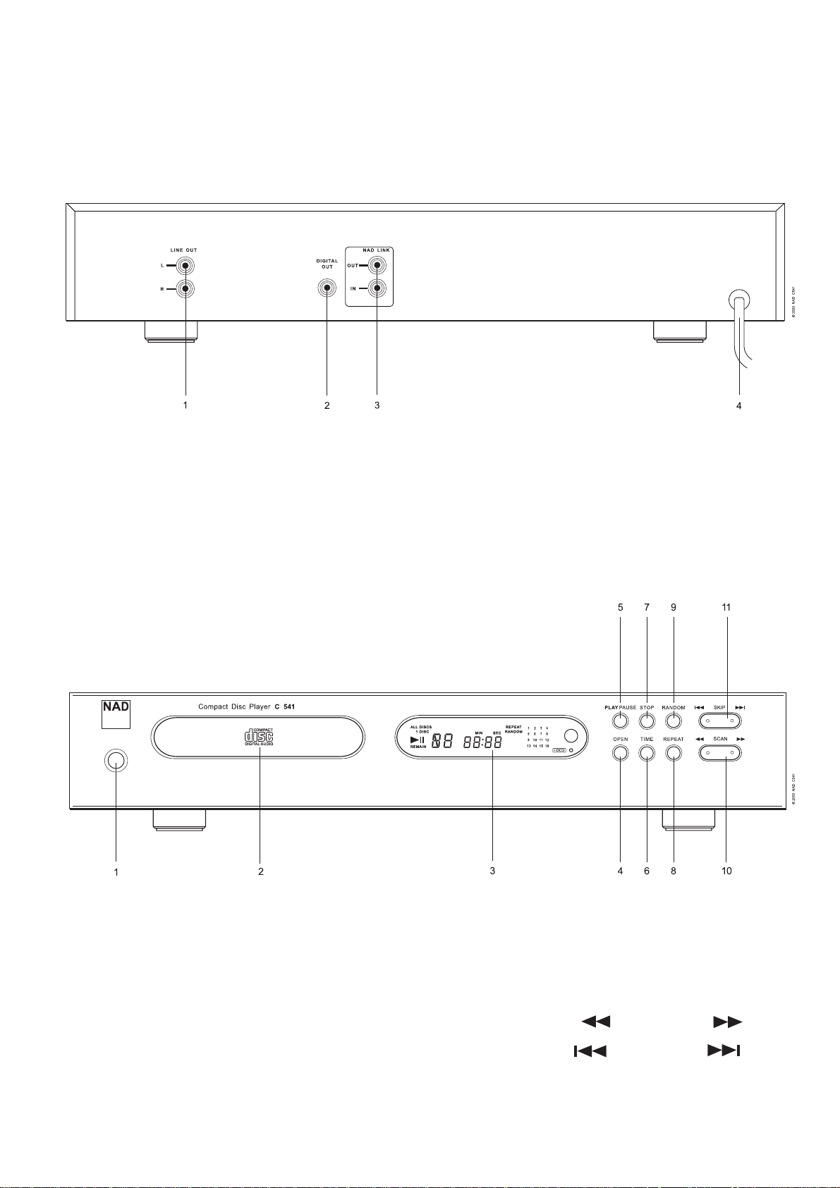
REAR PANEL / FRONT PANEL
REAR PANEL
FRONT PANEL
1. LINE OUT
2. DIGITAL OUT
3. NAD LINK
4. AC LINE CORD
1. POWER ON / OFF
2. DISC DRAWER
3. DISPLAY
4. OPEN
5. PLAY / PAUSE
6. TIME
7. STOP
8. REPEAT
9. RANDOM
10. SCAN Back ( ) / Forward ( )
11. SKIP Back ( ) / Forward ( )
Page 6
6
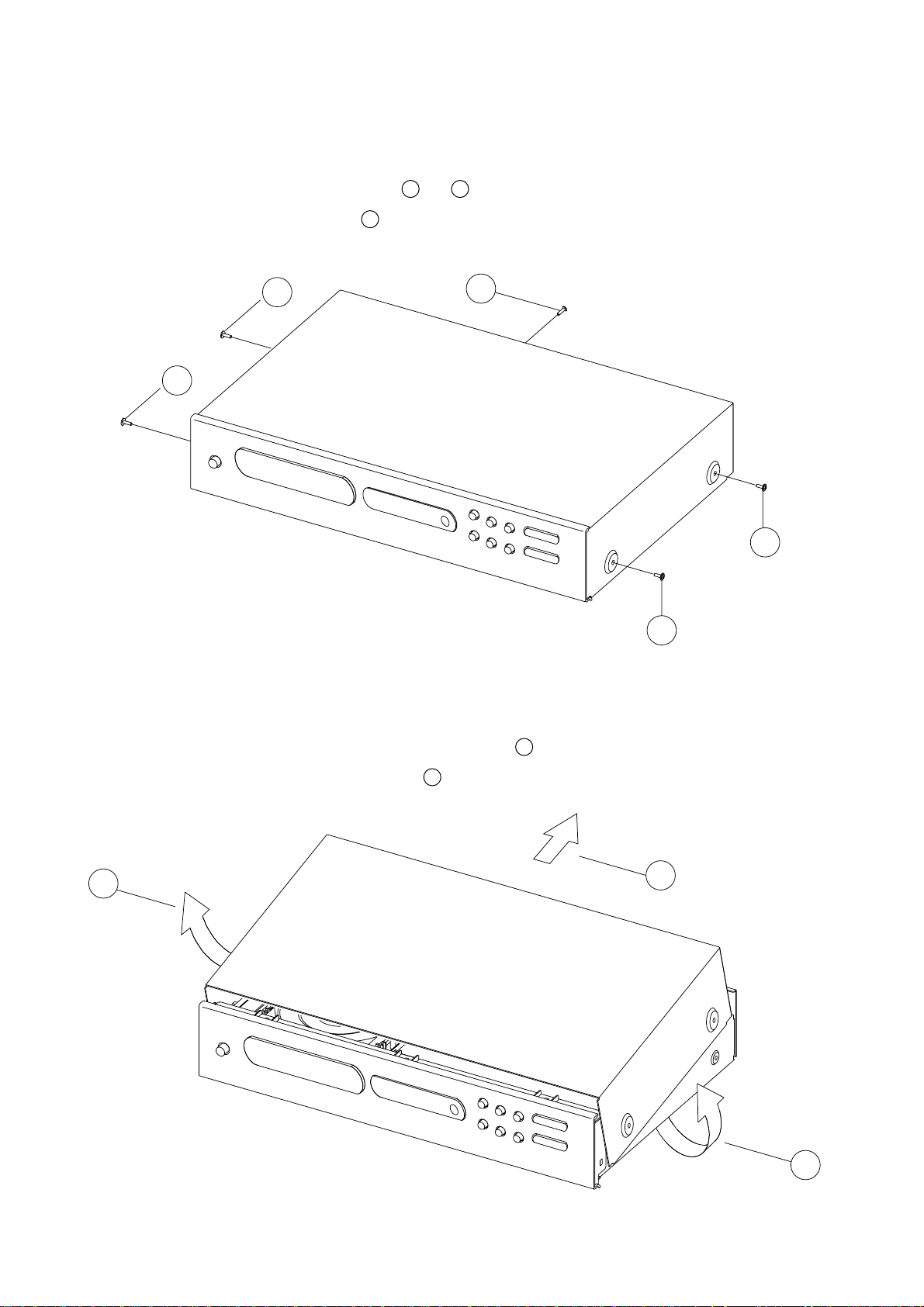
DISASSEMBLY INSTRUCTIONS
1. Remove machine screws M 4.0 x 6.0 ( 1 to 4 ) from the side panels.
Remove tapping screw 3.0 x 8.5 5 from the back panel.
Refer to Figure No.1.
Figure No.1
2. Pull both sides of the TOP COVER slightly outwards 6 and tilt approx. 35˚ and then remove
in the direction as indicated by the arrow 7 . Refer to Figure No.2.
Figure No.2.
5
4
3
1
2
7
6
6
Page 7
7
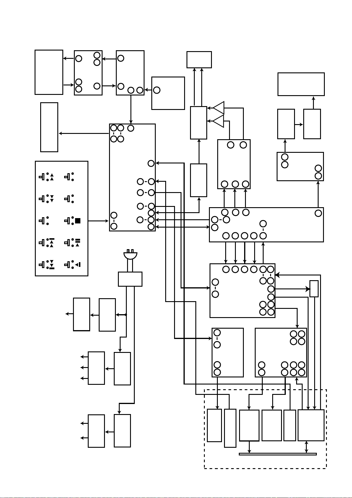
BLOCK DIAGRAM
NAD LINK
M319
RCA JACK
NAD LINK
M501
VFL DISPLAY
REPEAT
KEYBOARD
OUT
IN
M111M112
M104
11
109
RANDOM
TIME
1312
U403
8
74HC00 NAND GATE
M106
M108
15
U402
MICRO-
NAD LINK
CONTROLLER
9
11
64
1 16
19 24
U401 LC866008
SYSTEM CONTROL CPU
& VFL DISPLAY DRIVER
57 58
O/P
J317
RCA
CD AUDIO
1
8
M113
SENSOR
REMOTE
39
40
33
34
35
36
47
41
4344 48
JACK
L
R
Q301-Q304
MUTE
Q401- Q403
MUTE CIRCUIT
M318
DIGITAL
OUTPUT
RCA JACK
U305
U306
L
R
16
13
DAC
U302
PCM1732
1
2
3
42
44
43
65
67
63
23
24
14
10 11
13
U301
LC78621
M303
EMC FILTER
3 6
U403
SIGNAL
DIGITAL
L301
DIGITAL COIL
74HC00
NAND GATE
PROCESSOR
2 4
56
M110 M109
-22V
M101 M103 M102
D510-D511
ZENER DIODES
-12V
U502-3,U506
U501,U507
+8V +5V +12V 5V
POWER
TRANSFORMER
DIODES
RECTIFIER
D506-D508
POWER
ANALOGUE
POWER
DIGITAL
M500
DIODES
RECTIFIER
D501-D504
DIODES
RECTIFIER
D514-D517
AC POWER I / P
TOFF
30 31
5 6
2 10
MOTOR
LOADING
TGL
CLV-
CLV+
35
34
39
U101 LA9240
ANALOG SIGNAL
PROCESSOR/SERVO
U701 LB1641
MOTOR DRIVER
MOTOR
SPINDLE
LIMIT SWITCH
LOADING MOTOR
40
EFM
4
4443
1
63 62
16
29
15
27
U201 LA6541
6
5
SLED
FOCUS &
TRACKING
MOTOR
11
10
MOTOR
13
28
3
18
DRIVER
21
26
20
25
PU-IN
LIMIT SWITCH
UP
PICK
Q101
CD MECHANISM UNIT
DISC
Page 8

8
WIRING DIAGRAM
NAD
IN/OUT
TO CHASSIS
M120A
KEYBOARD
MAIN BOARD
M502
TRANSFORMER
RED
BROWN
M102 (15 PINS)
M105 (6 PINS)
M101 (5 PINS)
BLACK
M505B
M505A
CD MECHANISM
DISPLAY BOARD
NEUTRAL
LIVE
LIVE BOARD
Page 9
9
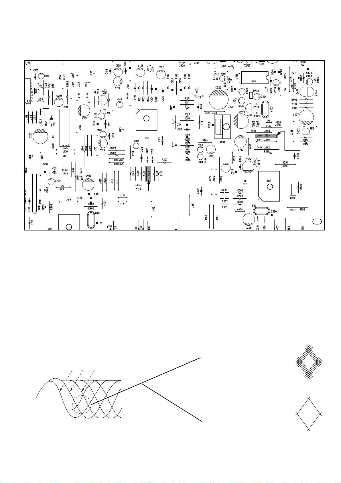
RF PATTERN TESTING
NAD - C 541 PCB TESTING POINTS DIAGRAM
TESTING PROCEDURE
(1) Load the test disc (Sony Test CD YEDS-7) and set the unit into PLAY mode.
(2) Connect the scope to R132 (Pin 41 of U101) and DGND (J334).
Scope setting: Coupling : AC.
Vertical sensitivity : 0.2 V/ div.
Horizontal time base : 0.5 µS/div.
(3) Observe the waveform is 2.0V p-p +/-5% and the eye pattern is at its best shape (see FIG. 1).
FIG. 1 (a) FIG. 1 (b) Poor eye pattern
FIG. 1 (C) Good eye pattern
3T 4T 5T — 11T
Testing
Point
J334
Testing Point
R132
Page 10

10
IMPORTANT NOTES
INSTRUCTION FOR HANDLING OPTICAL SYSTEM BLOCK PICK-UP
Electrostatic breakdown of the laser diode in the optical system block may occur due to a potential difference caused by electrostatic charge accumulated on clothing, human body, etc. A ground
must be provided as follows to prevent any electrostatic charge during unpacking or repair work.
1. Ground for Human Body
Be sure to wear a ground band (1M ohm) that is properly to remove any static electricity that may
be charged on the body.
2. Ground for Work Bench
Be sure to place a conductive sheet (1M ohm) or copper plate with proper grounding on the work
bench or other surface on which the pick-up is to be placed.
3. Because the static electricity charge on the clothing does not discharge through the body
grounding band, do not let clothing to get in contact with the pick-up unit.
PRECAUTIONS FOR CHECKING BEAM EMISSION
The laser beam of this unit is focused on the reflecting surface of the objective lens in the optical
system block. Therefore, keep your eyes at least 12 inches (30 cm) away from the objective lens
when the laser diode is ON.
(Operation Check Method for Laser Diode and Focus Search Function.)
When the POWER switch is turned ON after the chucking plate is removed, observe the objective
lens and confirm that the following operations are performed properly.
(The optical system should be at the lead-in area position when it is checked at this time.)
(1) The laser should be at the innermost position after the chucking plate is removed.
(2) The diffused light of the laser beam can be seen when the POWER switch is turned ON.
(3) Vertical (up and down) movement of the ojective lens (2 or 3 times) will take place.
INCORRECT CORRECT
NOTE: Laser diodes are so susceptible to damage from
static electricity that even if a static discharge does not
ruin the diode, it can shorten its life or cause it to work
improperly.
1.Grounding band
1M ohm
1M ohm
2.Conducttive Sheet
or Copper Plate
Page 11

11
PRECAUTIONS WHEN CHANGING LASER PICK-UP
When removing the pick-up assembly, short circuit the PCB tracks on the optical block as show in
the drawing in order to protect the pick-up before removal.
NOTE: Replacement pick-up assemblies are supplied with the PCB pattern already protected.
DO NOT REMOVE THE SHORT CIRCUITS UNTIL YOU HAVE FINISHED FITTING THE PICK-
UP.
Caution:
Laser diodes are extremely susceptible to damage from static electricity. Even if a static discharge does not ruin the diode, it can shorten its life or cause it to work improperly. When replacing the pick-up, use a conductive mat, a grounded soldering iron, and so on, to protect the laser
diode from static damage.
Ground Conductive
Wrist Band for Body
Ground Line
Less than
10 ohm
Conductive Gum Mat
Soldering
Iron with
Ground
wire
Protective soldering place
for laser diode
Page 12

12
PCB LAYOUT
LIVE BOARD
KEY BOARD
DISPLAY BOARD
Page 13

1413
MAIN BOARD
Page 14

15 16
SCHEMATIC DIAGRAM
D+5VRXDGND
HDCD
D+5VRXDGND
DGND
HDCD
HDCD
HDCD
HDCD
0V
0V
0V
2.4V
1.6V
0V
0V
0V
4.9V
0V
4.8V
*0V
4.8V
*1.2V
4.9V
*0V
5V0V4.3V
2.2V
5V
0V
0V0V5V5V2.4V
0V
1.1V
*2.7V
1.2V
*2.7V
*7.4V
7.8V
2.5V
2.5V
2.5V
3.4V
3.4V0V0V0V3.5V
3.5V
2.5V
2.5V
4.8V
4.9V
*7.4V 7.8V
*5V 0V
2.4V
2.5V
*3.3V
3.5V
*2.9V
3.5V
0V0V0V
3.4V
3.4V
2.5V
2.5V
5V
*7.4V
7.8V
0V0V5V5V5V5V4.9V
4.9V
4.9V
4.9V
0V
4.8V
2.6V
2.4V
∆4.9V
#0V
#4.9V
∆0V
2.4V
2.4V
2.4V
2.4V
2.4V
2.4V
2.4V
2.4V
2.4V
2.4V
2.4V
2.4V
2.4V
2.4V2V3.7V
0V
0V
0V
0V
0V
0V
2.4V
2.4V
2.4V
2.4V
2.4V
2.4V
2.4V
2.4V
2.4V
2.4V
5V
0V
3.3V
1.6V
0V
4.7V
4.8V
0V
0V
0V
0V *1.8V
5V
5V
0V
4.9V
4.9V
5V
2.3V
2.2V0V0V
2.4V
2.3V
4.9V
4.9V
4.9V
0V
0V
2.4V
2.4V
3V *1.6V
0V *1.8V
0V
0V 0V 0V 0V 0V 0V 0V 0V 0V 0V 0V 0V 0V2.4V 2.4V5V
0V
0V
*1.4V
4.6V
0V
1.7V
5V
1.5V
*0.3V 0V
2.3V
2.5V
2.5V
0V
*0.4V 0V
0V
0V
0V
0V
0V
0V
4.9V
4.9V
2.3V
0.2V
*0V 4.9V
0V
0.7V
0.5V
0V
0V
7.8V
7.8V
0.7V
0.5V
∆0.06V #4.2V
*1.2V 3V
2.4V
2.4V
2.1V
2.3V
2.3V
0V
0V
2.4V
2.5V
0V
5V
5V
0V
5V
0V
4.9V
0V
2.3V
0V
0V
2.4V
2.5V
5V
5V
5V
HDCD
R428
560R
DGND
RESISTORS: M- METAL FILM
F- FUSIBLE
CARBON FILM UNLESS OTHERWISE SPECIFIED.
NOTE: 1. RESISTORS, UNLESS OTHERWISE SPECIFIED, ARE 1/8W.
2. ALL CERAMIC CAPACITORS, UNLESS OTHERWISE SPECIFIED, ARE 50V 10%.
3. COMPONENTS MARKED “ ” ARE SAFETY CRITICAL PARTS.
4. VOLTAGE SPECIFIED ON THE IC’S PIN WHICH DOES NOT HAS MARKING IS IN STOP MODE,
MARKED WITH “*” IS PLAY MODE, “#” IS TRAY OPEN MODE AND “∆“ IS TRAY CLOSE MODE.
Page 15

64
VCC163LDS62LDD
61
BH160PH1
59
LF258VR57REFI56VCC255FSS54DRF53CE52DAT51CL50CLK49DEF
48
NC
47
TBC
46
FSC
45
DGND
44
SLI
43
SLC
42
RFS–
41
RFSM
40
CV+
39
CV–
38
SLOF
37
HFL
36
TES
35
TOFF
34
TGL
33
JP+
32
JP–
31
SL+
30
SL–
29
SLD
28
SLEQ
27
SPD
26
SP–
25
SPG
24
SPI
23SP22
AGND
21
FE–
20
FE
19
FA–
18
FA
17
FD–
1
FIN2
2
FIN1
3
E
4
F
5
TB
6
TE–
7
TE
8
TESI
9
SCI
10
TH
11
TA
12
TD–
13
TD
14
JP
15
TO
16
FD
REF
BAL
I/V
TE
T.SERVO & T.LOGIC
F.SERVO & F.LOGIC SPINDLE SERVO
SLC
APC
RF DET
VCA
RF Amp
µ - com
INTER FACE
VCA
SLED SERVO
17
IC BLOCK DIAGRAM
U101: LA9240
EFMO
DEFI
EFMIN
LRSY
C2F
ROMXA
DOUT
ASDACK
ASDFIN
ASDFIR
ASLRCK
DACKO
DFOLO
DFORO
LRCKO
FSEQ
CLV+
CLV–
V/P
PW,SBCK
SBSY,SFSY
WRQ,SQOUT
CQCK
COIN
RWC
DEMO
FST,FOCS
FZD
HFL,RES
TES,JP+
TOFF,JP–
THLD,TGL
EMPH
LASER
16M
4.2M
CS
CONT
EFLG
FSX
XIN
XOUT
XVDD,XVSS
CK2
RVDD,RVSS
MUTER
RCHP
RCHN
LVDD,LVSS
LCHN
LCHP
TGL
EFMO
VVDD
VVSS
PDO
ISET
PCK
TAI
TST11
TST10
TSET1
TEST2
TEST3
TEST4
TEST5
VDD
VSS
2K x 8-bit RAM
RAM address
generator
Interpolation
and muting
Antishock
interface
Digital
attenuator
8x oversampling
digital filters
Level meter
Peak meter
Crystal oscillator system
Timing generation
C1 AND C2 ERROR DETECTION
AND CORRECTION
FLAG PROCESSING
CLV DIGITAL
SERVO
SUBCODE
SEPARATION
Q CRC
MICROPROCESSOR
INTERFACE
Slice level
control
VCO clock Oscillator
Clock control
SYNCHRONIZATION
DETECTION
EFM DEMODULATION
SERVO
COMMAND
Digital
output
1bit DAC
10
9
6
3
5
21
2
69
37
801226
31
74
27
42
45
8
4
44
56
38
39
40
41
36
34
33
46
48
49
52
53
55
43
77
62
58
73
75
70
32
23,29
20,28
68,19
16,17
18
30
64
66
67
63,65
57,60
59,61
15
14
13
22
11
1
24,25
72
71
78
76,79
51,54
47,50
35
U301: LC78621ED
Page 16

18
1 28
ML/I
2
SLRCIN
2 27
MC/DEMDIN
3 26
MD/F
SS
BCKIN
Serial
Input
I/F
Mode
Control
I/F
SCK
BPZ Control
Crystal/OSC
XTI XTO CLKO VCC1 AGND1 VDDDGND
Power Supply
Power-On Reset
HDCD
8X
Oversampling
Digital Filter with
Enhanced
Multi-level
Delta Signal
Modulator
DAC
Low-pass
Filter
V
OUT
L
V
CC
2L
AGND2L
V
CC
2R
AGND2R
EXTL
V
OUT
R
EXTR
ZERO
Low-pass
Filter
DAC
LRCIN
DIN
MUTE
RST
MODE
CS/IWO
MD/FSS
MC/DEM
ML/I
2
S
BCKIN
4 25
MUTECLKO
5 24
MODEXTI
6 23
CS/1WOXTO
7
PCM1732U
22
RSTDGND
8 21
20
ZEROV
DD
9
GAINHDCD
10 19
VCC2LVCC2R
11 18
AGND2LAGND2R
12 17
EXTLEXTR
13 16
V
OUT
LV
OUT
R
14 15
VCC1AGND1
HDCD
Hidden
Code
Recovery
HDCD
Amplitude
Decoding
U302: PCM1732
INPUT
Port 3
Counter
Timers (2)
Interrupt
Control
Two Analog
Comparators
Port 2
I/O
(Bit Programmabel)
1
P24
P25
P26
P27
P28
XTAL 2
XTAL 1
P31
P32
P23
P22
P21
P20
GND
P02
P01
P00
P33
18
9 10
I/O
Vcc
ALU
OTP
Program
Counter
Machine
Timing & Inst.
Control
FLAG
Flegister
Pointer
General-Purpose
Register File
Port 0
GND
XTAL
1
VCC
2
MUTE
3
V IN1
4
VG 1
5
Vo1
6
Vo2
7
GND
8
GND
9
GND
10
Vo3
11
Vo4
12
VG2
13
V IN2
14
REG OUT
15
REG IN
30
VCC
29
V REF
28
V IN4
27
VG 4
26
Vo8
25
Vo7
24
GND
23
GND
22
GND
21
Vo6
20
Vo5
19
VG3
18
V IN3
17
CD
16
RES
Level shift
4
Level shift
1
BTL AMP
4
BTL AMP
1
11K½ 11K½
11K½ 11K½
Vcc
BTL AMP
3
BTL AMP
2
Level Shift
3
Level Shift
2
Regulator RESET
U402: NADLINK(MASKED) U201: LA6541D
Page 17

AMPLIFIER 1
OUTPUT
INVERTING
INPUT
NON-INVERTING
INPUT
V –
AMPLIFIER 2
V +
OUTPUT
INVERTING
INPUT
NON-INVERTING
INPUT
1
2
3
4
8
7
6
5
+ – – +
19
U305-U306: OPA2604
1A1 14 VCC
2B1 13 B4
3Y1 12 A4
4A2 11 Y4
5B2 10 B3
6Y2 9 A3
7GND 8 Y3
P1 OUT1 VCC2 OUT2 P2
3 2 8 10 9 7
4
5
1
6
VCC1
VZ
IN1
GND
IN2
Predriver
Input logic circuit
U403: 74HC00 U701: LB1641
P17/PWM
P16/BUZ
P15/SCK1
P14/SI1/SB1
P13/SO1
P12/SCK0
P11/SI0/SB0
P10/SO0
P07
P06
P05
P04
P02
P03
P01
P00
S0/T0
S1/T1
S2/T2
S3/T3
S4/T4
S5/T5
S6/T6
S7/T7
S8/T8
S9/T9
S10/T10
S11/T11
S13/T13
S12/T12
S14/T14
S15/T15
S29
S28
S27
S26
S25
S24
S23
S22
S21
S20
S19
S18
S17
S16
VP
VDDVPP
TEST 1
RES
XT1
XT2
VSS
CF1
CF2
VDD
P80/AN0
P81/AN1
P82/AN2
P83/AN3
P70/INTO
P71/INT1
P72/INT2/TOIN
P73/INT3/TOIN
48 47 46 45 44 43 42 41 40 39 38 37 36 35 34 33
1 2 3 4 5 6 7 8 9 10 11 12 13 14 15 16
49
50
51
52
53
54
55
56
57
58
59
60
61
62
63
64
32
31
30
29
28
27
26
25
24
23
22
21
20
19
18
17
Interrupt Control
Stand-by Control
Bus Interface
Port1
Port7
Port8
Base Timer
SIO0
SIO1
Timaer 0
Timaer 1
ADC
Bus
Bus
IR PLA
ROM
PC
ACC
B Reg
PSW
RAR
RAM
Stack Pointer
PORT 0
Watcher Dog Timer
C Reg
ALU
INT0-3
Noise Filter
Real Time
Service
XRAM
(128 bytes)
VFD Controller
High Voltage
Output
Clock
Generator
CF
RC
X'tal
U401: LC866008C IC401: System Block Diagram LC8660/08C
Page 18

20
TROUBLESHOOTING GUIDE
SET POWER SWITCH TO ON.
IS POWER TURNED ON ?
YES
CAN TRAY BE OPENED ?
YES
CAN TRAY BE CLOSED ?
YES
DOES INITIAL READING OCCUR ?
YES
NO NO NO
NO
CHECK FUSES
M507, M512-M514 OPEN ?
YES
M507,M512-M514 DEFECTIVE CRYSTAL M401 DEFECTIVE.
IS THERE OPEN/ CLOSE KEY SIGNAL
INPUT ? U401 PIN 39, 40
YESNO
CHECK OPEN/ CLOSE SIGNAL AT U401
PIN 39 PIN 40
TRAY OPEN H L
TRAY CLOSE L H
YES
IS LOADING MOTOR DRIVE CIRCUIT
OPERATION NORMAL ? U701, PIN 2,10
YES
LOADING MOTOR AND LEAD WIRE DEFECTIVE
OR LOADING PART OF MECHANISM DEFECTIVE.
CHECK LASER LIGHT ? DOES LENS MOVE UP AND DOWN ?
YES YES YES
CHECK LASER CIRCUIT CORRECT ?
YES
CONNECTION OR PICKUP DEFECTIVE.
CHECK POWER SUPPLY
CIRCUIT NORMAL ?
YES
IS OSCILLATOR CIRCUIT
OSCILLATING ?
NONO
NO
NO
NO NO
M101 SWITCH, DEFECTIVE
OR PATTERN AND CONNECTOR OPEN.
MICROPROCESSOR IC U401 DEFECTIVE.
MOTOR DRIVE IC U701 DEFECTIVE.
RF SIGNAL OUTPUT ?
YES
FEED MOTOR OR WIRING DEFECTIVE.
NO
U101 DEFECTIVE.
POWER SUPPLY PATTERNS OPEN
OR U501-U507 DEFECTIVE.
NO
U101 DEFECTIVE.
NO
CHECK FOCUS SIGNAL OUTPUT ?
CHECK CONNECTION OR PICKUP.
CAN DISC BE PLAYED ? CHECK TRACKING SERVO CIRCUIT CORRECT ? SERVO IC U101 OR U201 DEFECTIVE.
YES
AUDIO OUTPUT IS CORRECT ? IS POWER SUPPLY NORMALLY ? CHECK POWER SUPPLY PATTERNS.
YES
OK
NO
YES
CHECK DISC OR MECHANISM AND CONNECTOR
NO
YES
CHECK CLOCK PULSE AT PIN4 OF U302
YES
CHECK OUTPUT PULSE AT PIN 42,43,44 OF U301
YES
CHECK OUTPUT SIGNAL AT PIN 13,16 OF U302
YES
CHECK OUTPUT SIGNAL AT PIN 1,7 OF U305, U306
YES
CHECK OUTPUT SIGNAL AT PIN 7,1 OF U305, U306
YES
CHECK MUTE CIRCUIT Q301, Q302, Q303, Q304
YES
LINE OUT PLUG OR PATTERNS DEFECTIVE.
NO
NO
NO
NO
NO
NO
NO
NO
M302 OR U302 DEFECTIVE.
IC U301 DEFECTIVE.
IC U302 DEFECTIVE.
IC U305 OR U306 DEFECTIVE.
IC U305 OR U306 DEFECTIVE.
MUTE CIRCUIT DEFECTIVE.
Page 19

21
ELECTRICAL PARTS LIST
Reference No. Part No. Description
DISPLAY ASSEMBLY
PCB BOARD
1000 PCB-N0960C-DISP DISPLAY ASSEMBLY
LED
LED1 3700-2810-R LED RED 3MM SP L-93XHD
IR SENSOR
M113 4816-043T-3 IR SENSOR PIC-26043TM2 KODENSHI
VFL
M501 2460-1870-0 VFD 6-BF-271GK
KEYBOARD ASSEMBLY
PC BOARD
2000 PCB-N0960C-KEY KEYBOARD ASSEMBLY
RESISTORS
R601 4701-102J-C RCF 1/8W 1K 5% ATS
R602 4701-821J-C RCF 1/8W 820R 5% ATS
R603 4701-471J-C RCF 1/8W 470R 5% ATS
R604 4701-391J-C RCF 1/8W 390R 5% ATS
R605 4701-102J-C RCF 1/8W 1K 5% ATS
R606 4701-821J-C RCF 1/8W 820R 5% ATS
R607 4701-471J-C RCF 1/8W 470R 5% ATS
R608 4701-391J-C RCF 1/8W 390R 5% ATS
SWITCHES
M101-M104,M106 5200-3538-0 SWITCH, TACT SKHHBY 7MM HIGH
M108-M112 5200-3538-0 SWITCH, TACT SKHHBY 7MM HIGH
LIVE ASSEMBLY
PC BOARD
3000 *AH PCB-N0960C-LIVE LIVE ASSEMBLY
3000 *C PCB-N0961C-LIVE LIVE ASSEMBLY
CAPACITOR
C800 8910-0049-0 CAP400V 4700P DE7150F472MVA1KC
POWER SWITCH
M802 5200-3151-0-01 POWER SWITCH
TRANSFORMER
M810 *C 1806-2170-0 EMI FILTER TLN12UA 150W3R0
TRANSFORMER ASSEMBLY
TRANSFORMER
M500 1806-2512-0 TRANSFORMER N0870C I/P 120/230V TOROIDAL
FUSE
ASSEMBLY
Page 20

FUSES
M507 *AH 5120-0052-0 FUSE T1.6A 250V 5 x 20MM
M507 *C 5120-0050-0 FUSE T1.6A 250V 5 x 20MM
M512, M513 *AH 5120-0020-0 FU T1A 250V UL/CSA 5 x 20
M512, M513 *C 5120-0018-0 FU T1A 250V SEMKO/VDE
M514 *AH 5120-0026-0 FU T315MA L 250V UL/CSA
M514 *C 5120-0027-0 FU T315MAL 250V
MAIN ASSEMBLY
PC BOARD
4000 PCB-N0960C-MAIN MAIN ASSEMBLY
CAPACITORS
C101 150F-104K-2-FC CC 50V 0.1µF 10% AT
C104 153F-333J-5-MS CM 50V 0.033µF 5% RL
C105 150F-331K-2-FC CC 50V 330pF 10% AT 3.5x
C106 153F-473J-5-NR CM 50V 0.047µF 5% RL
C107 157F-104M-5-GMK CE 50V 0.1µF 20% RL
C108 153F-332J-5-KW CM 50V 3300pF 5% RL 6x12
C109 153F-154J-5-NLM CM 50V 0.15µ F 5% RL
C111,C113 150F-104K-5-II CC 50V 0.1µF 10% RL 5x5
C114 153F-683K-5-OS CM 50V 0.068µF 10% RL 8x
C115 153F-183J-5-KJ CM 50V 0.018µ F 5% RL
C116 153F-332J-5-KW CM 50V 3300pF 5% RL 6x12
C117 150F-101K-2-FC CC 50V 100pF 10% AT 3.5x
C118 157F-224M-5-GMK CE 50V 0.22µF 20% RL 4X7
C119 157E-475M-5-GMK CE 25V 4.7µ F 20% RL 4x7
C120 157C-226M-5-IUK CE 10V 22µ F 20% RL 5X11
C121 153F-332J-5-KW CM 50V 3300pF 5% RL 6x12
C122 15CH-050D-5-GG CTC 0/60 5pF 0.5pF RL
C123 153F-222J-5-IM CM 50V 2200pF 5% RL5X7
C124 15CH-120J-5-GG CTC 0/60 12pF 5% RL 4x4
C125 153F-333J-5-MS CM 50V 0.033µF 5% RL
C126 157E-106M-5-GMK CE 25V 10µF 20% RL 4X7
C127 153F-103J-5-IM CM 50V 0.01µF 5% RL 5X7
C128,C129 157B-107M-5-KMK CE 6.3V 100µF 20% RL
C130 153F-103J-5-IM CM 50V 0.01µF 5% RL 5X7
C131 153F-473J-5-NR CM 50V 0.047µF 5% RL
C132 157F-334M-5-GMK CE 50V 0.33µF 5% RL
C133 153F-102J-5-IM CM 50V 1000pF 5% RL5x7
C134 157C-476M-5-IMK CE 10V 47µF 20% RL 5X7
C135 157B-227M-5-LMK CE 6.3V 220µF 20% RL
C136 150F-104K-5-II CC 50V 0.1µF 10% RL 5x5
C137 153F-103J-5-IM CM 50V 0.01µF 5% RL 5X7
C138 157E-106M-5-GMK CE 25V 10µF 20% RL 4X7
C139 157B-107M-5-KMK CE 6.3V 100µ F 20% RL
C140 150F-104K-5-II CC 50V 0.1µF 10% RL 5x5
C141 157F-225M-5-GMK CE 50V 2.2µF 20% RL 4x7
C142 153F-102J-5-IM CM 50V 1000pF 5% RL5x7
C152 153F-103J-5-IM CM 50V 0.01µF 5% RL 5X7
C157 157C-477M-5-OVK CE 10V 470µ F 20% RL
C202 157C-108M-5-S5K CE 10V 1000µF 20% RL
C204 157D-106M-5-GMK CE 16V 10µF 20% RL 4x7
C205 153F-103J-5-IM CM 50V 0.01µF 5% RL 5X7
C301,C302 150F-104K-5-II CC 50V 0.1µF 10% RL 5x5
C303 153F-223J-5-LQ CM 50V 0.022µF 5% RL
C304,C308 157B-107M-5-KMK CE 6.3V 100µF 20% RL
C310 150F-104K-5-II CC 50V 0.1µF 10% RL 5x5
C311 150F-101K-2-FC CC 50V 100pF 10% AT 3.5x
22
Reference No. Part No. Description
Page 21

C313 153F-102J-5-IM CM 50V 1000pF 5% RL5x7
C320,C321 157D-106M-5-Iuf3 CE 16V 10µF 20% RL 5X11
C322 150F-104K-5-II CC 50V 0.1µF 10% RL 5x5
C323,C324 157D-106M-5-Iuf3 CE 16V 10µF 20% RL 5X11
C325 157Q-106M-5-IUK CE 35V 10µF 20% RL 5X11
C326,C327 150F-104K-5-II CC 50V 0.1µF 10% RL 5x5
C328,C329 15CH-200J-5-GG CTC 0/60 20pF 5% RL 4x4
C332 157D-106M-5-Iuf3 CE 16V 10µ F 20% RL 5X11
C334 157Q-106M-5-IUK CE 35V 10µF 20% RL 5X11
C350 150F-104K-5-II CC 50V 0.1µF 10% RL 5x5
C352,C353 150F-181K-2-FC CC 50V 180pF 10% AT
C356,C357 153F-272J-5-JM CM 50V 2700pF 5% RL
C362,C363 153I-472K-9-NL CM 63V 0.0047µF 10% RB
C366,C367 158F-681J-5-KW CP 50V 680pF 5% RL 6x12
C368,C369 157D-107M-5-SXF3 CE 16V 100µF 20% RL
C370 153F-103J-5-IM CM 50V 0.01µF 5% RL 5X7
C371-C374 157D-477M-5-X9F3 CE 16V 470µF 20% RL
C375,C376 157D-107M-5-SXF3 CE 16V 100µF 20% RL
C377-C379 153I-224J-9-NL CM 63V 0.22µF 5% RB 7.5x
C380,C381 150F-104K-5-II CC 50V 0.1µF 10% RL 5x5
C382 153I-224J-9-NL CM 63V 0.22µF 5% RB 7.5x
C383 157C-226M-5-IUK CE 10V 22µ F 20% RL 5X11
C384 153F-102J-5-IM CM 50V 1000pF 5% RL 5x7
C385 153F-222J-5-IM CM 50V 2200pF 5% RL 5X7
C386 150F-104K-5-II CC 50V 0.1µF 10% RL 5x5
C387 150F-103K-5-II CC 50V 0.01µF 10% RL 5x5
C401 150F-104K-5-II CC 50V 0.1µF 10% RL 5x5
C402 157B-107M-5-KMK CE 6.3V 100µ F 20% RL
C403,C404 15CH-330J-5-IG CTC 0/60 33pF 5% RL 5x4
C407 157D-108M-5-S9K CE 16V 1000µF 20% RL
C408 157D-226M-5-GMK CE 16V 22µF 20% RL
C409 150F-104K-5-II CC 50V 0.1µF 10% RL 5x5
C410 157D-106M-5-GMK CE 16V 10µF 20% RL 4x7
C411 153F-103J-5-IM CM 50V 0.01µF 5% RL 5X7
C412,C413 150F-104K-5-II CC 50V 0.1µF 10% RL 5x5
C414,C415 15CH-270J-5-GG CTC 0/60 27pF 5% RL 4x4
C416,C417 150F-104K-5-II CC 50V 0.1µF 10% RL 5x5
C418 157D-106M-5-GMK CE 16V 10µF 20% RL 4x7
C419 153F-103J-5-IM CM 50V 0.01µF 5% RL 5X7
C420 157D-106M-5-GMK CE 16V 10µF 20% RL 4x7
C440 150F-104K-5-II CC 50V 0.1µF 10% RL 5x5
C450 150F-104K-2-FC CC 50V 0.1µF 10% AT
C451 150F-103K-5-II CC 50V 0.01µF 10% RL 5x5
C501-C505 150F-104K-5-II CC 50V 0.1µF 10% RL 5x5
C506,C507 157E-108M-5-5$F3 CE 25V 1000µ F 20% RL
C508 157C-108M-5-S5K CE 10V 1000µF 20% RL
C510 157F-107M-5-OVK CE 50V 100µF 20% RL
C511 157C-227M-5-OMK CE 10V 220µF 20% RL 8x7
C512,C513 157E-106M-5-Iuf3 CE 25V 10µF 20% RL 5X11
C521 157F-226M-5-IUK CE 50V 22µF 20% RL 5X11
C522 157Q-476M-5-LUA CE 35V 47µF 20% RL 6.5X11
C525 157D-477M-5-X9F3 CE 16V 470µF 20% RL
C526 150F-104K-5-II CC 50V 0.1µF 10% RL 5x5
C527 157C-108M-5-X&F3 CE 10V 1000µF 20% RL
C528 150F-104K-5-II CC 50V 0.1µF 10% RL 5x5
C529 157D-338M-5-5&K CE 16V 3300µF 20% RL
C532 150F-104K-5-II CC 50V 0.1µF 10% RL 5x5
C533 157C-108M-5-S5K CE 10V 1000µF 20% RL
C534,C535 150F-104K-5-II CC 50V 0.1µF 10% RL 5x5
23
Reference No. Part No. Description
Page 22

24
C537,C538 157E-106M-5-Iuf3 CE 25V 10µF 20% RL 5X11
C539 153F-103K-5-IM CM 50V 0.01µ F 10% RL 5x7
C540-C543 150F-104K-5-II CC 50V 0.1µF 10% RL 5x5
C544 153F-103K-5-IM CM 50V 0.01µ F 10% RL 5x7
C545,C546 150F-104K-5-II CC 50V 0.1µF 10% RL 5x5
C560,C561 157E-107M-5-KUK CE 25V 100µF 20% RL
C701 153F-103K-5-IM CM 50V 0.01µ F 10% RL 5x7
C702 157C-476M-5-IMK CE 10V 47µF 20% RL 5X7
C703 150F-104K-5-II CC 50V 0.1µF 10% RL 5x5
C704 153F-103J-5-IM CM 50V 0.01µF 5% RL 5X7
C710 157B-107M-5-KMK CE 6.3V 100µ F 20% RL
C713 153F-223K-5-LQ CM 50V 0.022µF 10% RL 6.
DIODES
D101, D301-D302, D401-D402 4804-1480-2 DIODE 1N4148 AT
D403 4837-3V31-2 DZ 1/2W 3.1-3.5V ROHM AT
D409, D411-D415, D426, D431 4804-1480-2 DIODE 1N4148 AT
D501-D504 4804-0010-2 DIODE 1N4001 AT
D505 4840-1140-0 ZD 1.3W 3.3V 5% AT
D506-D508 4804-0010-2 DIODE 1N4001 AT
D510 4840-0850-0 ZD 1/2W 21.52-22.63V AT
D511 4837-5V61-2 DZ 1/2W 5.6V ROHM AT
D514-D517 4804-0010-2 DIODE 1N4001 AT
COILS
J507, L101 1801-100K-M COIL 10µH 10% BL7.0
L301 1802-0450-0 DIGITAL COIL 015-910-27BB
CRYSTAL
M302 2300-1910-0 X'TAL 16.9344MHZ +/-30PPM AT-51
M303 2704-0060-0 EMC FILTER
M401, M402 2703-6190-0 CR REASONATOR CSA 12MHz
JACKS
M317 2113-1300-0 2P RCA JACK W/R AU W/SHIELD
M318 2113-1170-0 1P RCA JACK YL AU HTJ-032-0
M319 2113-1121-0 2P RCA JACK Y/Y AU HSP-24V-22
TRANSISTORS
Q101 4851-015Y-5 TR 2SA1015-Y HFE120-240
Q301-Q304 4860-1780-5 TR 2SD655F HFE:600-1200
Q305 485A-1346-5 TR 2SA1346 HFE 50-100
Q308 4860-1780-5 TR 2SD655F HFE:600-1200
Q401 4860-0660-5 TR 2SA1015 (G.R.) RL
Q402 4851-012F-5 TR 2SD1012F/G HFE 160-560
Q403 4860-0660-5 TR 2SA1015 (G.R.) RL
Q502 485A-950Y-5 TR 2SA950-Y HFE 100-200
RESISTORS
D701 4701-752J-C RCF 1/8W 7.5K 5% ATS
J519 4715-4R75-2 RMF 1/4W 4.75R 1% AT
R101 4701-154J-C RCF 1/8W 150K 5% ATS
R102 4701-682J-C RCF 1/8W 6.8K 5% ATS
R103 4701-222J-C RCF 1/8W 2.2K 5% ATS
R106 4701-331J-C RCF 1/8W 330R 5% ATS
R107 4701-273J-C RCF 1/8W 27K 5% ATS
R108 4701-153J-C RCF 1/8W 15K 5% ATS
R109 4701-104J-C RCF 1/8W 100K 5% ATS
R110 4701-222J-C RCF 1/8W 2.2K 5% ATS
Reference No. Part No. Description
Page 23

R111 4701-203J-C RCF 1/8W 20K 5% ATS
R112 4701-223J-C RCF 1/8W 22K 5% ATS
R113 4701-153J-C RCF 1/8W 15K 5% ATS
R116 4701-393J-C RCF 1/8W 39K 5% ATS
R117 4701-152J-C RCF 1/8W 1.5K 5% ATS
R118 4701-103J-C RCF 1/8W 10K 5% ATS
R120 4701-333J-C RCF 1/8W 33K 5% ATS
R121,R123 4701-563J-C RCF 1/8W 56K 5% ATS
R124 4701-102J-C RCF 1/8W 1K 5% ATS
R125 4701-103J-C RCF 1/8W 10K 5% ATS
R126 4701-682J-C RCF 1/8W 6.8K 5% ATS
R131 4701-153J-C RCF 1/8W 15K 5% ATS
R132 4701-183J-C RCF 1/8W 18K 5% ATS
R133 4701-331J-C RCF 1/8W 330R 5% ATS
R134 4701-102J-C RCF 1/8W 1K 5% ATS
R135 4701-103J-C RCF 1/8W 10K 5% ATS
R137 4701-200J-C RCF 1/8W 20R 5% ATS
R138 4701-102J-C RCF 1/8W 1K 5% ATS
R139 4701-472J-C RCF 1/8W 4.7K 5% ATS
R201 4701-682J-C RCF 1/8W 6.8K 5% ATS
R204 4701-103J-C RCF 1/8W 10K 5% ATS
R207,R208 4701-562J-C RCF 1/8W 5.6K 5% ATS
R301 4701-681J-C RCF 1/8W 680R 5% ATS
R302 4701-563J-C RCF 1/8W 56K 5% ATS
R303 4701-122J-C RCF 1/8W 1.2K 5% ATS
R305 4701-104J-C RCF 1/8W 100K 5% ATS
R307 4701-103J-C RCF 1/8W 10K 5% ATS
R317 4701-102J-C RCF 1/8W 1K 5% ATS
R320 4701-471J-C RCF 1/8W 470R 5% ATS
R330 4701-752J-C RCF 1/8W 7.5K 5% ATS
R355,R356 4701-362J-2 RCF 1/8W 3.6K 5% AT
R359,R360 4701-163J-2 RCF 1/8W 16K 5% AT
R363,R364 4701-152J-C RCF 1/8W 1.5K 5% ATS
R367,R368 4701-222J-C RCF 1/8W 2.2K 5% ATS
R371,R372 4701-222J-C RCF 1/8W 2.2K 5% ATS
R373,R374 4701-104J-C RCF 1/8W 100K 5% ATS
R375,R376 4701-750J-C RCF 1/8W 75R 5% ATS
R377,R378 4701-472J-C RCF 1/8W 4.7K 5% ATS
R379,R380 4701-750J-C RCF 1/8W 75R 5% ATS
R381,R382 4701-472J-C RCF 1/8W 4.7K 5% ATS
R383 4701-151J-C RCF 1/8W 150R 5% ATS
R384 4701-750J-C RCF 1/8W 75R 5% ATS
R390 4717-221J-C RMF 1/2W 220R 5% ATS
R391-R393 4717-221J-C RMF 1/2W 220R 5% ATS
R394-R397 4701-472J-C RCF 1/8W 4.7K 5% ATS
R401,R402 4701-104J-C RCF 1/8W 100K 5% ATS
R403 4701-103J-C RCF 1/8W 10K 5% ATS
R404 4701-102J-C RCF 1/8W 1K 5% ATS
R405 4701-223J-C RCF 1/8W 22K 5% ATS
R406 4701-752J-C RCF 1/8W 7.5K 5% ATS
R407 4701-472J-C RCF 1/8W 4.7K 5% ATS
R408,R409 4701-101J-C RCF 1/8W 100R 5% ATS
R410 4701-104J-C RCF 1/8W 100K 5% ATS
R411 4701-101J-C RCF 1/8W 100R 5% ATS
R412 4701-472J-C RCF 1/8W 4.7K 5% ATS
R413 4701-473J-C RCF 1/8W 47K 5% ATS
R414 4701-104J-C RCF 1/8W 100K 5% ATS
R415 4701-752J-C RCF 1/8W 7.5K 5% ATS
R416 4701-473J-C RCF 1/8W 47K 5% ATS
25
Reference No. Part No. Description
Page 24

R418,R419 4701-272J-C RCF 1/8W 2.7K 5% ATS
R420-R427 4701-472J-C RCF 1/8W 4.7K 5% ATS
R428 4701-561J-C RCF 1/8W 560R 5% ATS
R501,R502 4701-241J-C RCF 1/8W 240R 5% ATS
R503,R504 4701-222J-C RCF 1/8W 2.2K 5% ATS
R517,R518,R520 4701-471J-C RCF 1/8W 470R 5% ATS
R523 4701-473J-C RCF 1/8W 47K 5% ATS
R701,R702 4701-472J-C RCF 1/8W 4.7K 5% ATS
R702 4701-472J-C RCF 1/8W 4.7K 5% ATS
ICS
U101 3130-6710-0 IC LA9240 ASP FOR CD QIP64E
U201 3130-6720-0 IC LA6541D 4-CHANNEL BTL DRIVER DIP30SLF
U301 3130-6700-0 IC LC78621ED DSP FOR CD QIP80E
U302 3131-9380-0 IC PCM1732 HDCD D/A CONVERTER
U305, U306 3130-9340-0 IC OPA2604 OPAMP DIP8 BURR-BROWN
U401 3130-9330-1 IC LC866008C MICRO MASK QFP64 SANYO
U402 3130-9320-0 IC NADLINK (MASKED) MICROCONTROLLER
U403 3130-4160-0 IC TC74HC00 NAND GATE
U501, U506 3130-2020-3 IC 7805 REG 5V 1.5A
U502 3130-5610-0 IC LM317T+ADJ REGULATOR
U503 3130-5620-0 IC LM337T-ADJ REGULATOR
U507 3130-2790-1 IC NJM7808FA +8V REG TO-220F
U701 3130-6560-0 IC LB1641 MOTOR DRIVER
26
NOTE: - The components identified by
mark are critical for risk of fire and electrical shock.
Replace only with part number specified.
- <*AH > : USA, Canadian model only.
- <*C > : European model only.
- Capacitors : CP-Polystyrene, CM-Mylar, CE-Electrolytic, CC-Ceramic, CTC-NPO.
- Resistors : RMF-Metal Film, RCF- Carbon Film.
Reference No. Part No. Description
Page 25

27
MECHANISM EXPLODED VIEW
CD11CA
Page 26

28
MECHANISM EXPLODED VIEW PARTS LIST
ITEM Part No. Description Qty
1 4102-6101-0 RUBBER CUSHION (HARD) 2
2 4102-6102-0 RUBBER CUSHION (SOFT) 2
3 4102-6103-0 BASE 1
4 4102-6104-0 TRAY 1
5 4102-6105-0 CDM MOUNTING BASE 1
6 4102-6106-0 MAGNET HOLDER 1
7 4102-6107-0 SLIDE GEAR 1
8 4102-6108-0 PULLEY GEAR 1
9 4102-6109-0 DRIVE GEAR 1
10 4102-6110-0 PULLEY MOTOR 1
11 4102-6111-0 SQUARE BELT 1
12 4102-6112-0 MAGNET 1
13 4102-6113-0 LOADING MOTOR 1
14 4102-6114-0 SWITCH PUSH 2-1 2
15 4102-6115-0 CON JST 5P RT 1
16 4102-6116-0 MOTOR/SW.PCB 1
17 4102-6117-0 SCREW M3.0X8.0 1
18 4102-6118-0 PLATE MAGNET 1
19 4102-6213-0 LASER CD11CA-G 1
Page 27

29
EXPLODED VIEW OF LASER CD11CA-G
Page 28

30
ITEM Part No. Description Qty
1 4102-6214-0 ASSY PICKUP LASER P101N 1
2 4102-6215-0 ASSY MOTOR 6.0V SPINDLE 1
3 4102-6216-0 ASSY MOTOR SLED 6.0V 1
4 4102-6217-0 CHASSIS 1
5 4102-6218-0 COVER GEAR 1
6 4102-6219-0 SHAFT SLIDE 1
7 4102-6220-0 GEAR MIDDLE 1
8 4102-6221-0 GEAR DRIVE 1
9 4102-6222-0 SWITCH LEAF(PWB MOTOR) 1
10 4102-6223-0 PLUG 6P 1
11 4102-6224-0 PWB MOTOR 1
12 4102-6225-0 SCREW PAN PCS 2x3 4
13 4102-6226-0 SCREW SELF-TAPING FLT 2.6x6 2
EXPLODED VIEW PARTS LIST OF LASER CD11CA-G
Page 29

31
EXPLODED VIEW
0202
!
0101
0014
0202
0202
M317
U503
0205
0003
0013
0208
0018
!
U507
U501
0211
0226
U506
0205
0304
0202
0201
0005
0012
M500
!
0201
0027
0218
0002
0225
0205
0219
0008
0228
0001
0226
0227
0010
0022
0019
0023
0205
0202
0021
0007
0006
Page 30

32
ITEM Part No. Description Qty
0001 1465-5704-2 FASCIAW/SS PAINT 1R
0002 1402-3781-2 STRAP 1
0003*AH 1402-3518-0 CHASSIS W/SS PAINT 1
0003*C 1402-3519-0 CHASSIS W/SS PAINT 1
0005 1402-3530-0 COVER 1
0006 2442-1000-0 POWER BUTTON 1
0007 1464-6011-3 CD DOOR W/SS PAINT 1
0008 3716-4316-0 WINDOW LENS W/SS 1
0010 2444-1201-0 BUTTON TRIO 2
0012 4111-1131-0 CD DECK 1
0013 4152-4631-0 RUBBER FOOT 14MM HIGH 4
0014 4151-9461-0 STRAIN RELIEF BUSHING 4N-4 1
0018 4152-4641-0 CUSHION FOOT 4
0019 2444-1301-1 BUTTON RACKER 2
0021 4152-4331-0 POWER BUTTON BEZEL 1
0022 4154-0031-0 BEZEL TRIO 2
0023 4154-0091-0 BEZEL RACKER 2
0027 4104-3721-0 TRANSFORMER BRACKET 1
0101*AH 7009-3100-2 AC CORD 18AWGX2 SPT-2 D.INSULATED UL/CSA 1
0101*C 7009-3110-0 AC CORD SEMKO 1
0201 2900-4006-3010 M4X0.5PX6MM W/FLAT WASHER 8
0202 2954-3008-3000 T3X8MM SELF TAPPING 12
0205 2954-3008-0000 TAPPING 3X8MM B-TITE(YEL.ZN) 17
0208 2842-3367-0 METAL WASHER ID=3.3 OD=6.7 4
0211 2904-3006-0000 SCREW M3X6 4
0218 2954-3006-0000 3X6MM B-TITE (YEL.ZN) 2
0219 2954-4010-3000 SCREW TAP-C2 BH M4X10MM BZ CROSS 4
0226 2954-2006-0000 TAPPING SCREW 2X6 13
0227 2954-2608-0000 SCREW BT 2.6X8 7
0228 2950-2608-3000 SCREW PAN HEAD,B-TITE 2.6X8 BLACK 1
0304 1463-160B-0 CD TRANSIT LOCK (RED) 1
M500 1806-2512-0 TRANSFORMER I/P 120/230V 1
U501-U503 5400-9130-0 HEAT SINK FOR 7805 2438-17 3
U506-U507 5400-9130-0 HEAT SINK FOR 7805 2438-17 2
EXPLODED VIEW PARTS LIST
NOTE: - The components identified by
mark are critical for risk of fire and electrical shock.
Replace only with part number specified.
- <*AH > : USA, Canadian model only.
- <*C > : European model only.
Page 31

33
PACKING DIAGRAM
ITEM PART NO. DESCRIPTION Q’TY
36 1490-3783-0 POLYFOAM ENDCAP 2
37 1497-1332-1 UNIT POLYBAG 1
38 1497-1432-0 FASCIACOVER 1
39 4060-0530-0 BATTERIES 2
40 2103-7302-1 RCA CABLE 1
41 8900-2166-0 REMOTE CONTROL HANDSET 1
42 1497-1302-1 REMOTE CONTROL POLYBAG 1
43 4301-4105-0 INSTRUCTION MANUAL 1
44 1497-1062-0 MANUAL POLYBAG 1
45 1435-4200-1-2 CARTON BOX 1
Proprietary information for servicing purposes only. The information herein may not be used commercially without the prior written agreement of NAD Electronics International, Toronto, Canada.
36
44
43
37
38
39
40
45
36
42
41
Page 32

SERVICE MANUAL
© NAD 2001
C 541
COMPACT
DISC PLAYER
NAD ELECTRONICS INTERNATIONAL
TORONTO
 Loading...