

Page 1

Bolt Grips andNut Grips
http://support.mts.com
MTS Fundamental™
Accessories
100-230-712A
Page 2

Copyright information 2010 MTS Systems Corporation. All rights reserved.
Declaration This manual describes all the available MTS fastener fixtures. The actual fixtures
supplied to the customer depend on the specs and types of specimen and relevant
standards stated in the purchase contract. Refer to Appendix A in fixture
purchasing and usage.
Trademark information MTS is a registered trademark and MTS Fundamental is a trademark of MTS
Systems Corporation within the United States. These trademarks may be
protected in other countries.
Publication
information
MANUAL PART NUMBER PUBLICATION DATE
100-230-712A January 2011
2
Page 3

Contents
Introduction 5
Component Identification 6
Safety 11
Installation 17
Operation 21
Bolt Tests 21
Proof Load Test for Nuts 26
Tests for Other Types of Specimens 29
Appendix A 31
MTS Fundamental™ Bolt Grips and Nut Grips
3
Page 4

4
MTS Fundamental™ Bolt Grips and Nut Grips
Page 5

Introduction
The MTS Fundamental fixtures are designed for tension, proof load ,and wedge
load tests of bolts and nuts.
Thread Specifications Table
P
ART NUMBER THREAD SPECIFICATIONS
F-JLL305A1
F-JLL305A2
F-JLL605A1
F-JLL605A2
F-JLL106A1
F-JLL106A2
The bolt length (l) should be no less than 3 times of the nominal diameter of bolts
(d), l≥3d.
The fixtures can perform tension, proof load and wedge load tests specified by
the following standards:
• GB/T 1231-2006 Specification of hexagon bolts, hexagon nuts, and plain
washers for high strength structural bolting with large width across flats.
• GB/T 3098.1-2000 (idt ISO 898-1 :1999) Mechanical properties of fasteners
– Bolts, screws and studs.
• GB/T 3098.2-2000 (idt ISO 898-2 :1992) Mechanical properties of fasteners
– Nuts – Coarse thread.
M5 to M20
M5 to M24
M5 to M30
• GB/T 3098.4-2000 (idt ISO 898-6 :1994) Mechanical properties of fasteners
– Nuts – Fine pitch thread.
• ASTM F606-07 Internally Threaded Fasteners, Washers, Direct Tension
Indicators, and Rivets.
MTS Fundamental™ Bolt Grips and Nut Grips Introduction
5
Page 6
Component Identification
The fixture consists of two assemblies: upper assembly indicated by Figure 1 and
Figure 2; Lower assembly indicated by Figure 3 and Figure 4. The wedge faces
(Part 3) have markers for pairs, use wedge faces which have same markers
together.
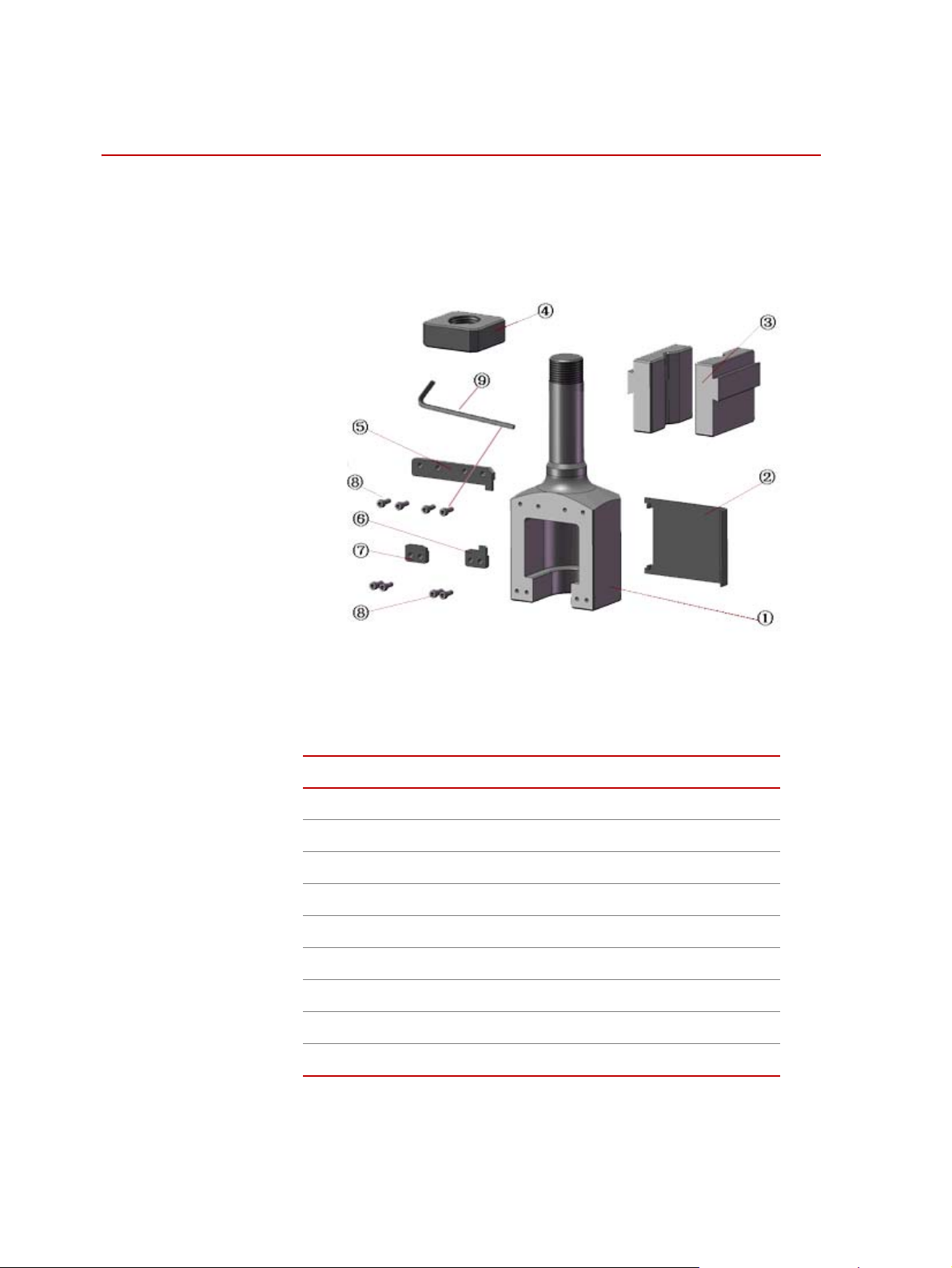
Figure 1 Parts of Upper Assembly
(F-JLL605A1/ F-JLL605A2/ F-JLL106A1/ F-JLL106A2)
Parts of Upper Assembly
C
ALLOUT DESCRIPTION
1
2
3
4
5
6
7
8
9
Upper Joint
Upper Protection Plate
Wedge Faces
Square Nut
Leading Block 1
Leading Block 2
Leading Block 3
Allen Screw M6×16
Hexagon Spanner (5mm)
6
Introduction
MTS Fundamental™ Bolt Grips and Nut Grips
Page 7
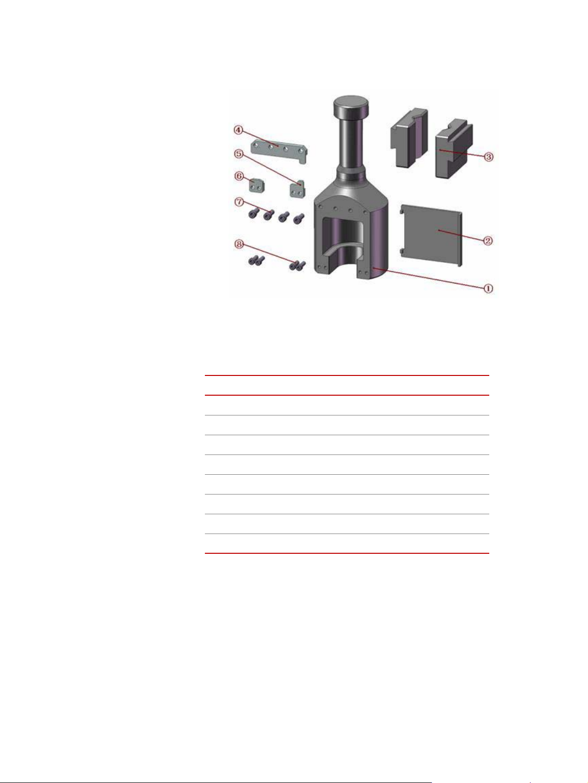
Figure 2 Parts of Upper Assembly
(F-JLL305A1/ F-JLL305A2)
Parts of Upper Assembly
C
ALLOUT DESCRIPTION
1
2
3
4
5
6
7
8
Upper Joint
Upper Protection Plate
Wedge Face
Leading Block 1
Leading Block 2
Leading Block 3
Allen Screw M6×16
Allen Screw M5×16
MTS Fundamental™ Bolt Grips and Nut Grips Introduction
7
Page 8
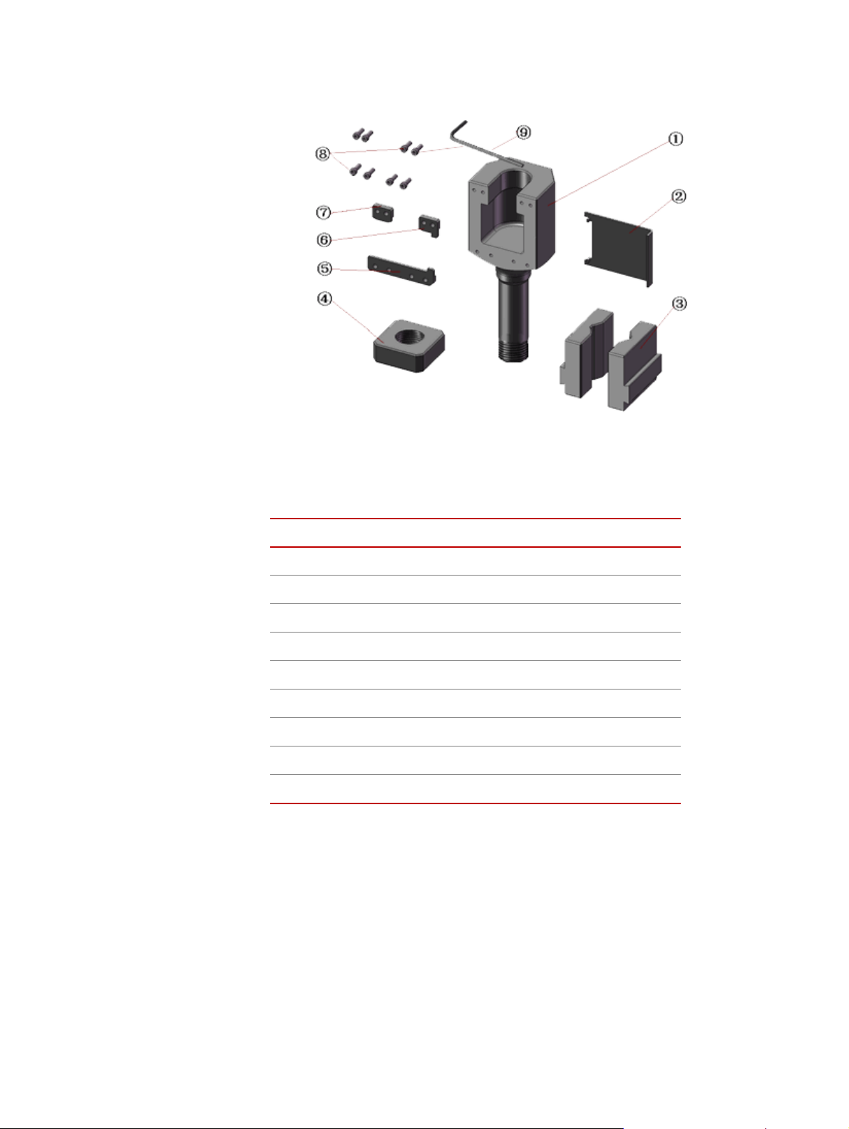
Figure 3 Parts of Lower Assembly
(F-JLL605A1/ F-JLL605A2/ F-JLL106A1/ F-JLL106A2)
Parts of Lower Assembly
C
ALLOUT DESCRIPTION
1
2
3
4
5
6
7
8
9
Lower Joint
Lower Protection Plate
Wedge Face
Square Nut
Leading Block 4
Leading Block 5
Leading Block 6
Allen Screw M6×16
Hexagon Spanner (5mm)
8
Introduction
MTS Fundamental™ Bolt Grips and Nut Grips
Page 9
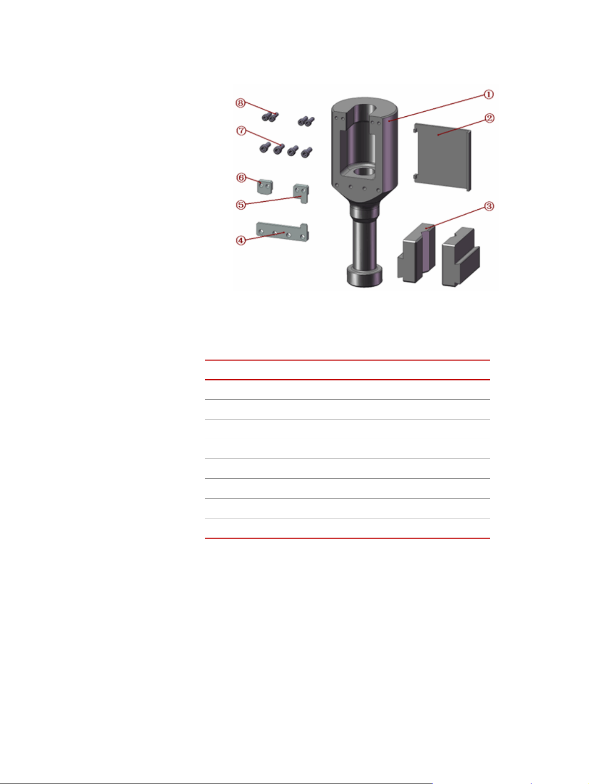
Figure 4 Parts of Lower Assembly
(F-JLL305A1/ F-JLL305A2)
Parts of Lower Assembly
ALLOUT DESCRIPTION
C
1
2
3
4
5
6
7
8
Lower Joint
Lower Protection Plate
Wedge Face
Leading Block 4
Leading Block 5
Leading Block 6
Allen Screw M6×16
Allen Screw M5×16
MTS Fundamental™ Bolt Grips and Nut Grips Introduction
9
Page 10

10
Introduction
MTS Fundamental™ Bolt Grips and Nut Grips
Page 11

Safety
General Safety
Practices: Grips and
Fixtures
This section provides general information about safety issues that pertain to MTS
systems that use grips and fixtures. These issues include statements to the
intended use and foreseeable misuse of the system, definitions for the graphical
hazard labeling that is affixed to your product, and other (more general) safety
information that relates to the high-pressure and high-performance characteristics
of MTS static hydraulic and electromechanical systems.
When you prepare to operate a system that includes grips or fixtures, ensure the
following:
• Do not allow personnel to operate the system who are not experienced,
trained, or educated in the inherent dangers associated with highperformance static hydraulics and who are not experienced, trained, or
educated with regard to the intended operation as it applies to this test
system.
• Do not disable safety components or features (including limit detectors,
light curtains, or proximity switches/detectors).
• Do not attempt to operate the system without appropriate personal safety
gear (for example, hearing, hand, and eye protection).
• Do not modify the system or replace system components using parts that are
not MTS component parts or effect repairs using parts or components that
are not manufactured to MTS specifications.
• Do not operate the grips or fixtures in an explosive atmosphere.
• Do not use the system in a test area where uncontrolled access to the test
system is allowed when the system is in operation.
• For servohydraulic systems, do not operate the system unless an interlock is
installed to monitor supply pressure into the HSM and initiate a system
interlock if a low or no pressure event occurs.
If you have system-related responsibilities (that is, if you are an operator, service
engineer, or maintenance person), you should study safety information carefully
before you attempt to perform any test system procedure.
You should receive training on this system or a similar system to ensure a
thorough knowledge of your equipment and the safety issues that are associated
with its use. In addition, you should gain an understanding of system functions
by studying the other manuals supplied with your test system. Contact MTS for
information about the content and dates of training classes that are offered.
MTS Fundamental™ Bolt Grips and Nut Grips Safety
11
Page 12

It is very important that you study the following safety information to ensure that
WARNING
your facility procedures and the system’s operating environment do not
contribute to or result in a hazardous situation. Remember, you cannot eliminate
all the hazards associated with this system, so you must learn and remain aware
of the hazards that apply to your system at all times. Use these safety guidelines
to help learn and identify hazards so that you can establish appropriate training
and operating procedures and acquire appropriate safety equipment (such as
gloves, goggles, and hearing protection).
Each test system operates within a unique environment which includes the
following known variables:
• Facility variables (facility variables include the structure, atmosphere, and
utilities)
• Unauthorized customer modifications to the equipment
• Operator experience and specialization
• Test specimens
Because of these variables (and the possibility of others), your system can
operate under unforeseen circumstances that can result in an operating
environment with unknown hazards.
Improper installation, operation, or maintenance of your system can result in
hazardous conditions that can cause death, personal injury, or damage to the
equipment or to the specimen. Common sense and a thorough knowledge of the
system’s operating capabilities can help to determine an appropriate and safe
approach to its operation.
The larger capacity grips are heavy.
Dropped grips can cause injury to personnel and damage to equipment.
Be sure to have help or a proper lifting device to position the grips for installation.
Read all manuals Study the contents of this manual and the other manuals provided with your
system before attempting to perform any system function for the first time.
Procedures that seem relatively simple or intuitively obvious may require a
complete understanding of system operation to avoid unsafe or dangerous
situations.
Avoid pinch/crush
Safety
12
points
Pinch points exist between the parts of the grip or fixture that contact the
specimen. Be aware of these pinch points when installing a specimen or working
around the grip or fixture during test setup. High forces generated when grip
pressure is activated can pinch, cut, or crush anything in the path of the grip/
fixture specimen contact area and cause serious injury. Stay clear of any potential
pinch points.
MTS Fundamental™ Bolt Grips and Nut Grips
Page 13

A crush point exists between the grips. Whenever possible, use tongs or a similar
tool when handling the specimen during specimen installation. Never allow any
part of your body to enter the path of machine movement or to touch moving
machinery, linkages, hoses, cables, specimens, and so forth. These present
serious crush points or pinch points.
Locate and read
hazard placards/labels
Know facility safe
procedures
Find, read, and follow the hazard placard instructions located on the equipment.
These placards are placed strategically on the equipment to call attention to areas
such as known crush points, electrical voltage, and high pressure hazards.
Most facilities have internal procedures and rules regarding safe practices within
the facility. Be aware of these safe practices and incorporate them into your daily
operation of the system.
Know controls Before you operate the system for the first time, make a trial run through the
operating procedures with the power off. Locate all hardware and software
controls and know what their functions are and what adjustments they require. If
any control function or operating adjustment is not clear, review the applicable
information until you understand it thoroughly.
Know specimen
properties
The user is responsible for understanding the characteristics of the test specimen.
Be sure to use appropriate personal protective equipment (clothing, hand gloves,
eye protection, and so forth).
Use protective guards such as cages, enclosures, and special laboratory layouts
when you work with hazardous test specimens (for example, brittle or
fragmenting materials or materials that are internally pressurized).
Have first aid available Accidents can happen even when you are careful. Arrange your operator
schedules so that a properly trained person is always close by to render first aid.
In addition, ensure that local emergency contact information is posted clearly and
in sight of the system operator.
Be aware of
component movement
with hydraulics off
Keep bystanders
safely away
MTS Fundamental™ Bolt Grips and Nut Grips Safety
The actuator rod can also drift down when hydraulics are turned off, hitting
anything in its path. This uncommanded movement is because of oil movement
between the pressure/return ports and oil blow by across the piston hub. Be aware
that this can happen and clear the area around the actuator rod when hydraulics
are turned off.
Keep bystanders at a safe distance from all equipment. Never allow bystanders to
touch specimens or equipment while the test is running.
13
Page 14

Wear proper clothing Do not wear neckties, shop aprons, loose clothing or jewelry, or long hair that
could get caught in equipment and result in an injury. Remove loose clothing or
jewelry and restrain long hair.
Remove flammable
fluids
Check bolt ratings and
torques
Practice good
housekeeping
Do not exceed the
Maximum Supply
Pressure
Remove flammable fluids from their containers or from components before you
install the container or component. If desired, you can replace the flammable
fluid with a non-flammable fluid to maintain the proper proportion of weight and
balance.
To ensure a reliable product, fasteners (such as bolts and tie rods) used in MTSmanufactured systems are torqued to specific requirements. If a fastener is
loosened or the configuration of a component within the system is modified, refer
to information in this product manual to determine the correct fastener, fastener
rating, and torque. Overtorquing or undertorquing a fastener can create a
hazardous situation due to the high forces and pressures present in MTS test
systems.
On rare occasions, a fastener can fail even when it is correctly installed. Failure
usually occurs during torquing, but it can occur several days later. Failure of a
fastener can result in a high velocity projectile. Therefore, it is a good practice to
avoid stationing personnel in line with or below assemblies that contain large or
long fasteners.
Keep the floors in the work area clean. Hydraulic fluid that is spilled on any type
of floor can result in a dangerous, slippery surface. Do not leave tools, fixtures,
or other items not specific to the test, lying about on the floor, system, or decking.
For hydraulic grips and fixtures, make sure that the hydraulic supply pressure is
limited to the maximum pressure defined by the grip or fixture identification (ID)
tag.
Do not disable safety
devices
Provide adequate
lighting
Provide means to
access out-of-reach
components
Wear appropriate
personal protection
Your system may have active or passive safety devices installed to prevent
system operation if the device indicates an unsafe condition. Do not disable such
devices as it may result in unexpected system motion.
Ensure adequate lighting to minimize the chance of operation errors, equipment
damage, and personal injury. You need to see what you are doing.
Make sure you can access system components that might be out of reach while
standing on the floor. For example, ladders or scaffolding might be required to
reach load cell connectors on tall load units.
Wear eye protection when you work with high-pressure hydraulic fluid,
breakable specimens, or when anything characteristic to the specimen could
break apart.
Wear ear protection when you work near electric motors, pumps, or other devices
that generate high noise levels. Some systems can create sound pressure levels
that exceed 70 dbA during operation.
Wear appropriate personal protection equipment (gloves, boots, suits, respirators)
whenever you work with fluids, chemicals, or powders that can irritate or harm
the skin, respiratory system, or eyes.
14
Safety
MTS Fundamental™ Bolt Grips and Nut Grips
Page 15

Handle chemicals
safely
Whenever you use or handle chemicals (for example, cleaning fluids, hydraulic
fluid, batteries, contaminated parts, electrical fluids, and maintenance waste),
refer to the appropriate MSDS documentation for that material and determine the
appropriate measures and equipment required to handle and use the chemical
safely. Ensure that the chemical is disposed of appropriately.
Know system
interlocks
Interlock devices should always be used and properly adjusted. Interlock devices
are designed to minimize the chance of accidental damage to the test specimen or
the equipment. Test all interlock devices for proper operation immediately before
a test. Do not disable or bypass any interlock devices, as doing so could allow
hydraulic pressure to be applied regardless of the true interlock condition. The
Reset/Override button is a software function that can be used to temporarily
override an interlock while attempting to gain control of the system.
Know system limits Never rely on system limits such as mechanical limits or software limits to
protect you or any personnel. System limits are designed to minimize the chance
of accidental damage to test specimens or to equipment. Test all limits for proper
operation immediately before a test. Always use these limits and adjust them
properly.
Do not disturb sensors Do not bump, wiggle, adjust, disconnect, or otherwise disturb a sensor (such as
an accelerometer or extensometer) or its connecting cable when hydraulic
pressure is applied.
Ensure secure cables Do not change any cable connections when electrical power or hydraulic pressure
is applied. If you attempt to change a cable connection while the system is in
operation, an open control loop condition can result. An open control loop
condition can cause a rapid, unexpected system response which can result in
severe personal injury, death, or damage to equipment. Also, ensure that all
cables are connected after you make any changes in the system configuration.
Stay alert Avoid long periods of work without adequate rest. In addition, avoid long periods
of repetitious, unvarying, or monotonous work because these conditions can
contribute to accidents and hazardous situations. If you are too familiar with the
work environment, it is easy to overlook potential hazards that exist in that
environment.
Contain small leaks Do not use your fingers or hands to stop small leaks in hydraulic or pneumatic
hoses. Substantial pressures can build up, especially if the hole is small. These
high pressures can cause the oil or gas to penetrate your skin, causing painful and
dangerously infected wounds. Turn off the hydraulic supply and allow the
hydraulic pressure to dissipate before you remove and replace the hose or any
pressurized component.
Stay clear of moving
equipment/avoid crush
points
Stay clear of mechanical linkages, connecting cables, and hoses that move
because you can get pinched, crushed, tangled, or dragged along with the
equipment. High forces generated by the system can pinch, cut, or crush anything
in the path of the equipment and cause serious injury. Stay clear of any potential
crush points. Most test systems can produce sudden, high-force motion. Never
assume that your reactions are fast enough to allow you to escape injury when a
system fails.
MTS Fundamental™ Bolt Grips and Nut Grips Safety
15
Page 16

Know the causes of
unexpected actuator
motions
The high force and velocity capabilities of MTS actuators can be destructive and
dangerous (especially if actuator motion is unexpected). The most likely causes
of unexpected actuator response are operator error and equipment failure due to
damage or abuse (such as broken, cut, or crushed cables and hoses; shorted wires;
overstressed feedback devices; and damaged components within the servocontrol
loop). Eliminate any condition that could cause unexpected actuator motion.
16
Safety
MTS Fundamental™ Bolt Grips and Nut Grips
Page 17

Installation
The grips are usually assembled before shipment.
Inspect and clean the
parts
Assembly Refer to the component identification illustrations in the Introduction section for
F-JLL305A1
F-JLL305A2
F-JLL605A1
F-JLL605A2
F-JLL106A1
F-JLL106A2
Installation
Make sure you have all the parts. Check to see if the parts are correct. All parts
should be free of deformities or surface damages, and the screw holes should be
free of iron filings. Clean all parts before assembling.
the location of parts in the following paragraphs.
1. Mount the Leading Block 1 on the Upper Joint with an Allen Screw. The
uneven side of the Leading Block 1 should face the upper joint to form a
slot.
2. Insert the Upper Protection Plate into the slot and mount the Leading Block
2 and Leading Block 3 on the upper joint with an Allen Screw, so as to
mount the upper protection plate to the upper joint.
3. Repeat Steps 1 and 2 for the lower assembly.
Note When tightening the Allen screws, adjust the clearance of the leading
blocks and check that they are parallel. Make the protection plate slip
smoothly in the slots which are formed by the leading blocks and the
upper/lower joint.The fixtures must be stored with anti-rust oil applied.
Installing fixtures requires you to operate the equipment, which can cause
expected grip or crosshead movements.
Unexpected grip or crosshead movements can cause personal injury and
damage to the equipment.
Take every precaution to avoid unexpected grip and crosshead movements while
installing the fixtures.
MTS Fundamental™ Bolt Grips and Nut Grips Installation
17
Page 18

Open the grips of the testing machine. Make sure all of the small pistons of grips
Baffle Board
Cushion Plate
Upper Crosshead
Hexgon Spanner (6mm)
for M8
×16 Allen Screws
withdraw totally. Dismount the existing wedge faces from the grips and clean the
grooves.
F-JLL605A1
F-JLL605A2
F-JLL106A1
F-JLL106A2
Install the upper assembly according to actions shown in Figure 5.
Figure 5 Installation Procedure of Upper Assembly
1. Pick out two wedge faces which have the same marks, and mount one
wedge face into the upper grip as per ① and lock it with the baffle-board
(the baffle-board is used to prevent the wedge from moving during the test).
2. Mount another wedge face into the upper grip as per ② and lock it with the
baffle-board.
3. Insert the square nut between the wedge faces and the grip as per ③ .
4. Mount the upper assembly on the square nut as per ④, ⑤. Make the column
of the upper joint touch the surface of the V-shape groove of the wedge
faces.
5. Close the upper grip.
6. Use similar steps to install the lower assembly to the lower grip.
18
Installation
MTS Fundamental™ Bolt Grips and Nut Grips
Page 19

F-JLL305A1
Upper Crosshead
Baffle-Board
Cushion Plate
F-JLL305A2
Install the upper assembly according to actions shown in Figure 6.
Figure 6 Installation Procedure of Upper Assembly
1. Pick out two wedge faces which have the same marks, and mount one
wedge face into the upper grip as per ① and lock it with the baffle-board.
2. Mount another wedge face into the upper grip as per ② and lock it with the
baffle-board.
3. Mount the upper assembly on the square nut as per ③, ④. Make the column
of the upper joint touch the surface of the V-shape groove of the wedge
faces.
4. Close the upper grip.
5. Use similar steps to install the lower assembly to the lower grip.
MTS Fundamental™ Bolt Grips and Nut Grips Installation
19
Page 20

20
Installation
MTS Fundamental™ Bolt Grips and Nut Grips
Page 21

Operation
Contents Bolt Tests 21
Bolt Tests
Specimen Refer to Thread Specs Table in the Introduction section of this manual.
Proof Load Test for Nuts 26
Tests for Other Types of Specimens 29
Testing is dangerous because the broken specimen may be projected
violently from the testing zone.
The projected specimen can cause personal injury.
Close the protection plates of the fixtures and clear the personnel in front of the
fixtures before testing.
Check the diameter and length of the specimen; make sure they can meet the
requirement of the fixtures.
To ensure a valid test, the specimen should be free of any thread damages or
other deformities.
Proof load test Choose appropriate loading plates and threaded adapters for the specimen.
There are two types of loading plates and threaded adapters for different
specimens.
• Figure 7 shows the structure and installation manner for specimens of M5 to
M10.
• Figure 8 shows the structure and installation manner for specimen of M12 to
M30.
MTS Fundamental™ Bolt Grips and Nut Grips Operation
21
Page 22

The test can not be performed with the wrong loading plates and threaded
1
2
3
4
5
6
adapter.
Be sure to choose the appropriate loading plates and threaded adapters for the
specimen.
Figure 7 Proof Load Test (M5–M10)
ALLOUT DESCRIPTION
C
22
Operation
1
2
3
4
5
6
Flat Loading Plate(M5–M10)
Specimen
Threaded Adapter (M5-M10)
Spec Mark
Lower Protection Plate
Upper Protection Plate
MTS Fundamental™ Bolt Grips and Nut Grips
Page 23

Figure 8 Proof Load Test (M12–M30)
1
2
3
WARNING
C
ALLOUT DESCRIPTION
1
2
3
Debris can be discharged as a result of testing.
Debris can cause injury to personnel and damage to equi pment.
Be sure to close the protection plates of the fixture and clear the personnel in front
of the fixture before testing.
Loading Plate (M12–M30)
Specimen
Threaded Adapter (M12-M30)
Tensile test You can install the fixture and specimen the same as with the proof load test.
Wedge load test Choose appropriate wedge loading plates and threaded adapters for the specimen.
There are two types of wedge loading plates and threaded adapters for different
specimens.
• Figure 9 shows the structure and installation manner for specimens of M5 to
M10.
• Figure 10 shows the structure and installation manner for specimens of M12
to M30.
MTS Fundamental™ Bolt Grips and Nut Grips Operation
23
Page 24

Figure 9 Loading Plate (M5-M10)
Figure 10 Wedge Loading Plate (M12-M30)
The test can not be done if mounting the specimen on the opponent
position.
Be sure to make the loading plate surface engraved with "UP" on top and touching
the head of the bolt during the test.
24
Operation
There are spec marks on the wedge loading plates and threaded adapters, choose
appropriate loading plates and threaded adapters for the specimen (See Figure
11).
There are three kinds of wedge angles 4°, 6° and 10°, choose the appropriate
wedge loading plate to do the test.
You can do the test after completing the installation of fixture and specimen.
MTS Fundamental™ Bolt Grips and Nut Grips
Page 25

Debris can be discharged as a result of testing.
WARNING
Upper Protection Plate
Lower Protection Plate
Spec Mark
Debris can cause injury to personnel and damage to equi pment.
Be sure to close the protection plates of the fixture and clear the personnel in front
of the fixture before testing.
Figure 11 Wedge Load Test
CALLOUT DESCRIPTION
1
2
3
4
5
MTS Fundamental™ Bolt Grips and Nut Grips Operation
Wedge Loading Plate (M5–M10)
Specimen (M5–M10)
Threaded Adapter (M5–M10)
Wedge Loading Plate (M12–M30)
Threaded Adapter (M12–M30)
25
Page 26

Proof Load Test for Nuts
WARNING
Choose appropriate fixtures for the specimen. There are two kinds of fixtures for
different specimens (See Figure 12 and Figure 13).
All of the loading plates, threaded rods, high strength bolts and threaded adapters
have spec marks. Choose those parts according to the marks. For same thread
specs, the hole of the nuts’ loading plate is smaller than that of the bolts’ loading
plate. Do not misuse these loading plates.
Debris can be discharged as a result of testing.
Debris can cause injury to personnel and damage to equi pment.
Be sure to close the protection plates of the fixture and clear the personnel in front
of the fixture before testing.
Proof load test for nuts
(M5 to M10)
Choose appropriate loading plates and threaded rods for the specimen. A
threaded adapter of M12 should also be used. Screw the M12 thread of the thread
rod into the threaded adapter, Screw the other end of the thread rod into the
specimen (see Figure 12).
26
Operation
MTS Fundamental™ Bolt Grips and Nut Grips
Page 27

Proof load test for nuts
Upper Protection Plate
Lower Protection Plate
(M12 to M30)
Choose appropriate loading plates, nut loading plate and high strength bolt. See
Figure 13 for installation.
Figure 12 Proof Load Test for Nuts (M5-M10)
ALLOUT DESCRIPTION
C
1
2
3
4
Specimen (M5–M10)
Nut Loading Plate (M5–M10)
Threaded Rod (M5–M10)
Threaded Adapter (M12)
MTS Fundamental™ Bolt Grips and Nut Grips Operation
27
Page 28

Figure 13 Proof Load Test for Nuts (M12-M30)
Spec Mark
ex. N M12
Lower Protection
Plate
Upper Protection
Plate
ALLOUT DESCRIPTION
C
1
2
3
4
Loading Plate (M12–M30)
High-Strength Bolt (M12–M30)
Nut loading Plate (M12–M30)
Specimen (M12–M30)
28
Operation
MTS Fundamental™ Bolt Grips and Nut Grips
Page 29

Tests for Other Types of Specimens
By using appropriate loading plates, thread rods, thread adapters, and high
strength bolts, the fixtures can perform tests for specimens of fine pitch threads
and inch threads. Double-headed studs can also be tested. If you want to test
these kinds of specimens, you must state it clearly in your order.
T ests for specimens of
fine pitch threads
Tests for specimen of
inch threads
If you want to run tests for bolts, nuts, and studs which have fine pitch thread,
you need to change threaded adapters and high strength bolts (or threaded rods).
If you want to run the tests for bolts, nuts, and studs which have inch threads, you
need to change loading plates, wedge loading plates, threaded adapters, and high
strength bolts (or threaded rods).
MTS Fundamental™ Bolt Grips and Nut Grips Operation
29
Page 30

Tests for studs If you want to run tests for studs, you should use high strength nuts (no less than
Lower
Protection Plate
Upper
Protection Plate
class 12). One end of the stud should be connected to the high strength nut; the
other end be connected to the threaded adapter. Figure 14 illustrates the
installation manner. Refer to bolt proof load test for details.
Figure 14 Tests for Studs (M5–M30)
Tests for Studs
C
ALLOUT DESCRIPTION
1
2
3
4
High Strength Nut (No Less Than Class 12)
Loading Plate (M5–M30
Specimen (M5–M30)
Threaded Adapter (M5–M30)
30
Operation
MTS Fundamental™ Bolt Grips and Nut Grips
Page 31

Appendix A
Optional Fixture References
M5,M6,
M7,M8,M10
M12,M14,M16,M18,
M20,M22,M24,M27,M30
E
XAMPLES OF
MARK
REMARK
Bolts Threaded adapter Determined by
Loading plate M6,M20 aperture
4° wedge loading plate 4°×M20
6° wedge loading plate 6°×M20
10° wedge loading
plate
Nuts M4 -
M10
M12M30
Loading plate
for nuts
Threaded rod Determined by
Threaded
adapter
(M12)
Loading plate -- Determined by the
High strength
bolt
the specimen and
test method, one
for each
Determined by
the specimen,
one each
the specimen,
one each
One for all M12 see note
Determined by the
specimen and test
method, one for each
-- N-M6
specimen, one
Determined by the
specimen, one
M6,M20
10°×M20
M6
M20 see note
designed by
medium
clearance as
per GB/T
5227
Nut loading
plate
Note:
The loading plates and threaded adapter (M12) used in the proof load test of nuts are the same as the
loading plates and threaded adapter (M12) used in tensile test of bolts. Therefore, only one set is
necessary for both tests.
MTS Fundamental™ Bolt Grips and Nut Grips Appendix A
Determined by the
specimen, one
N-M20
31
Page 32

m
MTS Systems Corporation
Http://www.mts.com/en/global/index.asp
 Loading...