

Page 1

Multipurpose Elite Test Design Guide
100-229-376 F be certain.
Page 2

© 2013 MTS Systems Corporation. All rights reserved.
Trademark Information
MTS, FlexTest, RPC, and TestWare are registered trademarks and MTS Acumen, MTS TestSuite, Station
Builder, and Station Manager are trademarks of MTS Systems Corporation within the United States. These
trademarks may be protected in other countries. All other trademarks are the property of their respective
owners.Microsoft and Windows NT are registered trademarks of Microsoft Corporation. All other trademarks
or service marks are property of their respective owners.
Proprietary Software
Software use and license is governed by MTS’s End User License Agreement which defines all rights
retained by MTS and granted to the End User. All Software is proprietary, confidential, and owned by MTS
Systems Corporation and cannot be copied, reproduced, disassembled, decompiled, reverse engineered,
or distributed without express written consent of MTS.
Software Verification and Validation
MTS software is developed using established quality practices in accordance with the requirements detailed
in the ISO 9001 standards. Because MTS-authored software is delivered in binary format, it is not user
accessible. This software will not change over time. Many releases are written to be backwards compatible,
creating another form of verification. The status and validity of MTS’s operating software is also checked
during system verification and routine calibration of MTS hardware. These controlled calibration processes
compare the final test results after statistical analysis against the predicted response of the calibration
standards. With these established methods, MTS assures its customers that MTS products meet MTS’s
exacting quality standards when initially installed and will continue to perform as intended over time.
Manual Part Number—Publication Date—Release
100-229-376 F—August 2013—TestSuite MP 2.6 or
later
100-229-376 E—January
2013—TestSuite MP 2.5
100-229-376 D—December
2012—TestSuite MP 2.4
Page 3

Contents
1.0 Technical Support 7
2.0 Preface 11
3.0 Designing a Test 15
1.1.0 How to Get Technical Support........................................................................................................7
1.2.0 Before You Contact MTS................................................................................................................7
1.3.0 If You Contact MTS by Phone........................................................................................................9
1.4.0 Problem Submittal Form in MTS Manuals...................................................................................10
2.1.0 Before You Begin..........................................................................................................................11
2.2.0 Documentation Conventions.........................................................................................................11
3.1.0 Introduction...................................................................................................................................16
3.2.0 Test Design WorkFlow..................................................................................................................16
3.2.1.0 Using the Multipurpose Application with Controller Software.....................................17
3.2.1.1.0 Launching MPE or MPX.................................................................................17
3.2.1.2.0 Creating a Desktop Shortcut That Includes a Controller................................18
3.2.1.3.0 Multipurpose Application Startup Overview..................................................18
3.2.2.0 Creating Tests Overview................................................................................................19
3.2.3.0 Test Activities Overview................................................................................................19
3.2.3.1.0 Deleting and Disabling Test Activities............................................................21
3.2.3.2.0 Variables Overview.........................................................................................22
3.2.3.3.0 Information for an Operator............................................................................23
3.2.4.0 Working with Test-Run Display Devices.......................................................................24
3.2.5.0 Test Execution Overview...............................................................................................24
3.2.6.0 Model 494.05 Handset Station Activities.......................................................................26
3.2.7.0 Generating a Report in MP.............................................................................................27
3.2.8.0 Generating a Report Using the Excel Reporter Add-In.................................................28
4.0 Working with Resources 29
4.1.0 Resources......................................................................................................................................30
4.2.0 Starting MPE and Connecting to a Controller...............................................................................30
4.3.0 Station Congurations...................................................................................................................32
4.4.0 Controller Resources.....................................................................................................................32
4.5.0 Resource Mapping.........................................................................................................................33
4.6.0 Ofine Test Design.......................................................................................................................34
4.7.0 Resources That Allow Dimension Changes..................................................................................36
Multipurpose Elite Test Design Guide 3
Page 4

5.0 Creating Tests 37
5.1.0 Installing MTS TestSuite Simulation Software.............................................................................38
5.2.0 Creating Ramp and Cycle Test......................................................................................................38
5.2.1.0 Ramp and Cycle Test Design Overview.........................................................................38
5.2.2.0 Opening a Station Conguration and Starting the MPE Application............................40
5.2.3.0 Creating an Empty Test..................................................................................................41
5.2.4.0 Adding a Ramp Activity.................................................................................................41
5.2.5.0 Adding a Cycle Activity.................................................................................................43
5.2.6.0 Adding a Second Ramp Activity....................................................................................44
5.2.7.0 Adding a Signal Scope Monitor.....................................................................................45
5.2.8.0 Checking the Test Procedure..........................................................................................47
5.2.9.0 Adding Variables............................................................................................................48
5.2.10.0 Adding an Input Variables Activity..............................................................................50
5.2.11.0 Adding Parallel Paths and a Data Acquisition Activity...............................................52
5.2.12.0 Running the Test Procedure.........................................................................................54
5.3.0 External Commands......................................................................................................................55
5.3.1.0 External Command Test Overview................................................................................55
5.3.2.0 Controls That Affect External Command.......................................................................56
5.3.3.0 Simulating an External Command Input in the Station Conguration..........................58
5.3.4.0 Simulating a Sine Wave Command with a Calculation..................................................58
5.3.5.0 Setting Station Manager Application Command Options..............................................59
5.3.6.0 Showing the Station Manager Application Setpoint and Span Controls........................60
5.3.7.0 Starting the MPE Application and Creating a New Test Shell.......................................60
5.3.8.0 Adding an External Command Activity.........................................................................61
5.3.9.0 Adding a Signal Scope Monitor.....................................................................................62
5.3.10.0 Set MPE Application Command Settings....................................................................63
5.3.11.0 Starting the Test Procedure and Observing the Response............................................64
5.3.12.0 Stop the Test Procedure and Observe the Response.....................................................67
5.3.13.0 Resume the Test and Change Setpoint and Span.........................................................67
5.4.0 External Command Considerations...............................................................................................69
5.4.1.0 External Command Activity...........................................................................................69
5.4.2.0 Starting External Commands..........................................................................................69
5.4.3.0 Stopping External Command Activity...........................................................................69
5.4.4.0 Overriding System Setpoint and Span............................................................................70
6.0 Creating Advanced Tests 71
6.1.0 Introduction...................................................................................................................................72
6.2.0 Working with Proles...................................................................................................................72
6.2.1.0 Prole Test Overview.....................................................................................................73
6.2.2.0 Controls That Affect Proles.........................................................................................74
4 Multipurpose Elite Test Design Guide
Page 5

6.2.3.0 Creating a Prole............................................................................................................75
6.2.4.0 Creating Controller Resource Actions that Map to the Prole......................................76
6.2.5.0 Starting the MPE Application and Creating a New Test Shell.......................................78
6.2.6.0 Adding a Prole Activity...............................................................................................78
6.2.7.0 Adding a Monitor Display to Show the Prole Waveform............................................80
6.2.8.0 Adding a Monitor Display to Track Prole Passes........................................................81
6.2.9.0 Adding a Monitor Display to Show When Part of the Prole Plays Out.......................81
6.2.10.0 Start the Test Procedure and Observe the Response....................................................82
6.2.11.0 Considerations for Prole Design................................................................................84
6.2.11.1.0 Prole Types..................................................................................................84
6.2.11.2.0 Using ALC with the Prole Activity.............................................................84
6.2.11.3.0 General Prole Syntax Requirements...........................................................86
6.2.11.4.0 Header Data Syntax.......................................................................................86
6.2.11.5.0 Action and Counter Syntax...........................................................................87
6.2.11.6.0 Channel Header Syntax.................................................................................88
6.2.11.7.0 Channel Data Syntax.....................................................................................89
6.2.11.8.0 Dimensions....................................................................................................91
6.2.11.9.0 Normalized Dimensions................................................................................92
7.0 MTS Controller Software 95
7.1.0 Software Concepts.........................................................................................................................96
7.1.1.0 Key Concepts about Using MTS TestSuite and Controller Software............................96
7.2.0 Setting Station Limits and Install the Physical Specimen.............................................................97
7.2.1.0 Setting Station Detector Limits......................................................................................97
7.2.2.0 Access and Set Detector Settings...................................................................................98
7.2.3.0 Resetting a Detector.......................................................................................................98
7.3.0 Use Manual Command to Install the Specimen............................................................................99
7.3.1.0 Manual Command Overview.........................................................................................99
7.3.2.0 Manually Position the Actuator to Install and Remove Specimens.............................101
7.4.0 Apply Offsets to the Input Signal (optional)...............................................................................102
7.4.1.0 Applying an Auto Offset to an Input Signal.................................................................102
7.4.2.0 Applying a Manual Offset to an Input Signal..............................................................102
7.5.0 Adding Station Resources...........................................................................................................103
7.5.1.0 Adding Existing Hardware Resources to a Station Conguration...............................104
7.5.2.0 Adding New Hardware to a Controller........................................................................104
8.0 Appendix A: MPE for MPT Users 105
8.1.0 About This Appendix..................................................................................................................106
8.2.0 Major Concepts...........................................................................................................................106
8.3.0 Control Panel and Options..........................................................................................................109
8.4.0 Editing Features...........................................................................................................................110
Multipurpose Elite Test Design Guide 5
Page 6

8.5.0 Command....................................................................................................................................111
8.6.0 Data Acquisition..........................................................................................................................113
8.7.0 Event Detectors...........................................................................................................................116
8.8.0 External Control..........................................................................................................................117
8.9.0 Performance................................................................................................................................118
8.10.0 General......................................................................................................................................118
8.11.0 Other..........................................................................................................................................119
6 Multipurpose Elite Test Design Guide
Page 7

1.0 Technical Support
1.1.0 How to Get Technical Support
Start with your manuals
The manuals supplied by MTS provide most of the inf ormation you need to use and maintain your equipment.
If your equipment includes software, look for online help and README files that contain additional product
information.
Technical support methods
MTS provides a full range of support services after your system is installed. If you ha ve any questions about
a system or product, contact Technical Support in one of the following ways.
Web site
Outside the U.S.
For technical support outside the United States, contact your local sales and service office. For a list of
worldwide sales and service locations and contact information, use the Global MTS link at the MTS web site:
www.mts.com > Global Presence > Choose a Region
www.mts.com > Contact Us (upper-right corner) > In the Subject field, choose
To escalate a problem; Problem Submittal Form
Worldwide: tech.support@mts.comE-mail
Europe: techsupport.europe@mts.com
Worldwide: 1 800 328 2255 - toll free in U.S.; +1 952 937 4000 - outside U.S.Telephone
Europe: +800 81002 222, International toll free in Europe
1.2.0 Before You Contact MTS
MTS can help you more efficiently if you have the following information available when you contact us for
support.
Multipurpose Elite Test Design Guide 7
Page 8

Know your site number and system number
The site number contains your company number and identifies y our equipment type (such as material testing
or simulation).The number is typically written on a label on your equipment before the system leaves MTS.
If you do not know your MTS site number, contact your sales engineer.
Example site number: 571167
When you have more than one MTS system, the system job number identifies your system.You can find
your job number in your order paperwork.
Example system number: US1.42460
Know information from prior technical assistance
If you have contacted MTS about this problem before, we can recall your file based on the:
• MTS notification number
• Name of the person who helped you
Identify the problem
Describe the problem and know the answers to the following questions:
• How long and how often has the problem occurred?
• Can you reproduce the problem?
• Were any hardware or software changes made to the system before the problem started?
• What are the equipment model numbers?
• What is the controller model (if applicable)?
• What is the system configuration?
Know relevant computer information
For a computer problem, have the following information available:
• Manufacturer’s name and model number
• Operating software type and service patch information
• Amount of system memory
• Amount of free space on the hard drive where the application resides
• Current status of hard-drive fragmentation
• Connection status to a corporate network
Know relevant software information
For software application problems, have the following information available:
• The software application’s name , v ersion number, build number, and (if a v ailable) softw are patch number.
This information can typically be found in the About selection in the Help menu.
• The names of other applications on your computer, such as:
• Anti-virus software
• Screen savers
8 Multipurpose Elite Test Design Guide
Page 9

• Keyboard enhancers
• Print spoolers
• Messaging applications
1.3.0 If You Contact MTS by Phone
A Call Center agent registers your call before connecting you with a technical support specialist.The agent
asks you for your:
• Site number
• Name
• Company name
• Company address
• Phone number where you can be reached
If your issue has a notification number, please provide that number. A new issue will be assigned a unique
notification number.
Identify system type
To enable the Call Center agent to connect you with the most qualified technical support specialist available ,
identify your system as one of the following types:
• Electrodynamic material test system
• Electromechanical material test system
• Hydromechanical material test system
• Vehicle test system
• Vehicle component test system
• Aero test system
Be prepared to troubleshoot
Prepare to perform troubleshooting while on the phone:
• Call from a telephone close to the system so that you can implement suggestions made over the phone.
• Have the original operating and application software media available.
• If you are not familiar with all aspects of the equipment operation, have an experienced user nearby to
assist you.
Write down relevant information
In case Technical Support must call you:
• Verify the notification number.
• Record the name of the person who helped you.
Multipurpose Elite Test Design Guide 9
Page 10

• Write down any specific instructions.
After you call
MTS logs and tracks all calls to ensure that you receive assistance for your problem or request. If you have
questions about the status of your problem or have additional information to report, please contact Technical
Support again and provide your original notification number.
1.4.0 Problem Submittal Form in MTS Manuals
Use the Problem Submittal Form to communicate problems with y our software, hardware, man uals, or service
that are not resolved to your satisfaction through the technical support process.The form includes check
boxes that allo w you to indicate the urgency of y our problem and y our e xpectation of an acceptable response
time.We guarantee a timely response—your feedback is important to us.
You can access the Problem Submittal Form at www.mts.com > Contact Us (upper-right corner) > In the
Subject field, choose To escalate a problem; Problem Submittal Form
10 Multipurpose Elite Test Design Guide
Page 11

2.0 Preface
2.1.0 Before You Begin
Safety first!
Before you use y our MTS product or system, read and understand the safety information provided with your
system. Improper installation, operation, or maintenance can result in hazardous conditions that can cause
severe personal injury or death, or damage to your equipment and specimen. Again, read and understand
the safety information provided with your system before you continue. It is very important that you remain
aware of hazards that apply to your system.
Other MTS manuals
In addition to this manual, you may receive additional manuals in paper or electronic form.
You may also receiv e an MTS System Documentation CD. It contains an electronic copy of the manuals that
pertain to your test system.
Controller and application software manuals are typically included on the software CD distribution disc(s).
2.2.0 Documentation Conventions
The following paragraphs describe some of the conventions that are used in your MTS manuals.
Hazard conventions
Hazard notices may be embedded in this manual.These notices contain safety information that is specific
to the activity to be performed. Hazard notices immediately precede the step or procedure that may lead to
an associated hazard. Read all hazard notices carefully and f ollow all directions and recommendations.Three
different levels of hazard notices may appear in your manuals. Following are examples of all three levels.
(for general safety information, see the safety information provided with your system.)
DANGER:
Danger notices indicate the presence of a hazard with a high level of risk which, if
ignored, will result in death, severe personal injury, or substantial property damage.
WARNING:
Warning notices indicate the presence of a hazard with a medium lev el of risk which,
if ignored, can result in death, severe personal injury, or substantial property damage.
Multipurpose Elite Test Design Guide 11
Page 12
CAUTION:
Caution notices indicate the presence of a hazard with a low level of risk which, if
ignored, could cause moderate or minor personal injury or equipment damage, or
could endanger test integrity.
Other special text conventions
Important:
Important notices provide information about your system that is essential to its proper
function.While not safety-related, if the important information is ignored, test results may
not be reliable, or your system may not operate properly.
Note:
Notes provide additional information about operating your system or highlight easily
overlooked information.
Recommended:
Recommended notes provide a suggested way to accomplish a task based on what MTS
has found to be most effective.
Tip:
Tips provide helpful information or a hint about how to most efficiently accomplish a task.
Access:
Access provides the route you should follow to a referenced item in the software.
Example:
Examples show specific scenarios relating to your product and appear with a shaded
background.
Special terms
The first occurrence of special terms is shown in italics.
Illustrations
Illustrations appear in this manual to clarify text.They are examples only and do not necessarily represent
your actual system configuration, test application, or software.
Electronic manual conventions
This manual is available as an electronic document in the Portable Document File (PDF) format. It can be
viewed on any computer that has Adobe Acrobat Reader installed.
12 Multipurpose Elite Test Design Guide
Page 13

Hypertext links
The electronic document has many hypertext links displayed in a blue font. All blue words in the body text,
along with all contents entries and index page numbers, are hypertext links.When you click a hypertext link,
the application jumps to the corresponding topic.
Multipurpose Elite Test Design Guide 13
Page 14

Page 15

3.0 Designing a Test
Topics:
•
Introduction............................................................................................................................................16
•
Test Design WorkFlow...........................................................................................................................16
Multipurpose Elite Test Design Guide 15
Page 16

3.0 Designing a Test
3.1.0 Introduction
About this chapter
This chapter contains information about the MPE and Station Manager software, basic test design principles,
how tests are ex ecuted, and how information about test results is made av ailable. If you already f eel comfortable
with these test design principles and are ready to begin creating a basic ramp and cycle test, see Creating
Ramp and Cycle Test on page 38.
MTS Multipurpose Elite application overview
The MTS Multipurpose Elite (MPE) application is a sophisticated, general purpose test design application
that allows you to quickly and easily define comple x test designs.The role of either Administrator or Engineer
is required to access full functionality of MPE. Operators are allowed to access MPE but only with the same
rights they have in MPX.
Note:
MTS offers a companion application to MPE named Multipurpose Express (MPX).You cannot create
or modify tests with MPX; it is only to run existing tests . In cases where this manual ref ers to functionality
shared by both applications (such as running tests), the term “Multipurpose application” is used.
The Multipurpose Elite Test Design Guide contains the information you need to begin designing tests and
test reports with the MPE application. It includes the fundamental concepts of using the MPE application with
the MTS controller software to create and run tests.
This guide does not explain ev ery MPE application feature. Its goal is to introduce the most important features
of the application in the context of designing tests and test reports.
This chapter contains conceptual information pertinent to test designs. New users should read this chapter
before using the software to gain an overall understanding of the design process. Experienced users can
read this chapter to review the high-level activities associated with each design task. Detailed instructions to
perform the tasks in this chapter are included in other parts of this guide.
3.2.0 Test Design WorkFlow
This table shows the tasks a test designer may perform to prepare a test for an operator.The order in which
the tasks are shown is typical.
Typical Tasks for Preparing a Test
DescriptionActivityStep
Open a station configuration1
16 Multipurpose Elite Test Design Guide
Open a station configuration file with your MTS
controller software.
Page 17

3.0 Designing a Test
DescriptionActivityStep
2
select a new test
3
4
7
Add test activities and define their
properties
Add monitor display devices and
define their properties
Run the test to verify your design5
Create a test report template6
Ensure your test is ready for the
operator
Deliver your test to the operator8
With your station open, use the MPE application.Start the MPE application and
To create a test file, drag test activity icons onto the
Procedure tab.
Add monitor display devices, such as Signal Scope,
so you can monitor test progress.
Use MTS controller software and MPE together to run
tests.This step generates data in a test run.
Create a test report template by adding test variables
from your test run to a Microsoft Excel report.
You typically run your test again from the operator’s
perspective.You can choose to enhance your test
with special operator information.
When the test meets your requirements, deliver it to
the operator.You can choose to have your operators
use MP Express to run your test.
3.2.1.0 Using the Multipurpose Application with Controller Software
3.2.1.1.0 Launching MPE or MPX
Note:
If you have a desktop shortcut that opens the Station Manager application and then opens the MPE
or MPX application, you do not have to perf orm this procedure to start the Station Manager application
and load the station configuration. For more information about creating this desktop shortcut, see
Creating a Desktop Shortcut That Includes a Controller on page 18.
1. Start the Station Manager application by double-clicking the Station Manager icon located in the MTS 793
Software folder on the desktop; or from the Start menu, go to All Programs > MTS 793 Software >
Station Manager.The Open Station window appears.
2. In the Open Station window , select the station configuration file (.cfg) required to run the test (MTS FlexTest
40 with 2 Channel configuration).The .cfg file defines all the station resources that are available for a test.
3. Click Open.
4. The Station Manager window appears, which can be minimized.
Multipurpose Elite Test Design Guide 17
Page 18
3.0 Designing a Test
Important:
You must leav e the Station Manager application open, but y ou can minimize it so it does not appear
on your screen.
MTS TestSuite MPX is the intended operator interface. Do not make configuration changes in the
Station Manager application without training from MTS.
5. Open MPE or MPX by double-clic king its icon on your desktop; or from the Start menu, go to All Programs
> MTS TestSuite.The MP main window opens.You can now open a test.
Note:
If you have multiple stations, you can create individual shortcuts that are specific to each station.
3.2.1.2.0 Creating a Desktop Shortcut That Includes a Controller
Access:
Tools menu > Create Desktop Shortcut
Note:
This procedure only applies to MTS FlexTest controllers.
There are two types of desktop icons. One opens just the MTS TestSuite application, and the other will open
the controller and then open the MTS TestSuite application.The desktop shortcut that includes opening the
controller includes the configuration file name in its name, for example, “Multipurpose Express
(Station_Configuration.cfg).” If you have multiple stations, you can create a shortcut for each configuration
file.
To create the desktop shortcut that includes opening the controller:
1. Open your MTS TestSuite application: From the Start menu, select All Programs > MTS TestSuite >
application name.
2. From the Tools menu, click Create Desktop Shortcut.The Create Desktop Shortcut window opens.
3. Browse to the Station Configuration file you will be using, or type the file name in the Station Configur ation
box. Ensure that this configuration file contains the parameter and tuning sets that you want the operator
to use for the tests.
4. If the Controller Name box is not already populated, type the name of the controller you will be using.
5. Click OK.The configuration message that states that the shortcut was created on the desktop appears.
Click OK.
6. To avoid confusion, delete other MTS TestSuite application desktop shortcuts.
3.2.1.3.0 Multipurpose Application Startup Overview
After you open your station configuration with the Station Manager application, you open the Multipurpose
application, which automatically connects to your station configuration.
Multipurpose projects
When you select a new test, the test is automatically associated with an MTS TestSuite Project. A project is
a directory that organizes your test procedures, specimen information, and test run data.
18 Multipurpose Elite Test Design Guide
Page 19

Note:
MTS TestSuite projects are independent of the underlying controller, and are not related to MTS
controller projects or the MTS Project Manager application.
3.2.2.0 Creating Tests Overview
From the File menu, you can create new tests as follows:
Creating New Tests
DescriptionFile Menu Option
3.0 Designing a Test
New Test
New Test from
Template
New Test from Existing
Test
New Test from File
Creates a new test that does not contain test
data and has an undefined workflow. When
the workflow is defined, it can be extracted b y
saving the test as a template.
Creates a container file called a test that is
used to collect data and contains a copy of the
template. Each time you run the template on
a physical specimen, the application creates
a test run.The test run is a data set that
populates the test.
Note:
Only templates that are licensed appear
in the New Test from Template list.
Creates a new test that includes a copy of the
test without test run data.
Creates a new test from an XML file; typically
used in automation.
3.2.3.0 Test Activities Overview
Test activity sequence
Test activities execute from top to bottom in the order in which the y appear on the Pr ocedure tab .To execute
activities simultaneously, add Parallel Path activities to the test flow.You can also add While Loop, If-Else
Condition, and Periodic Time Event activities to control the test flow.
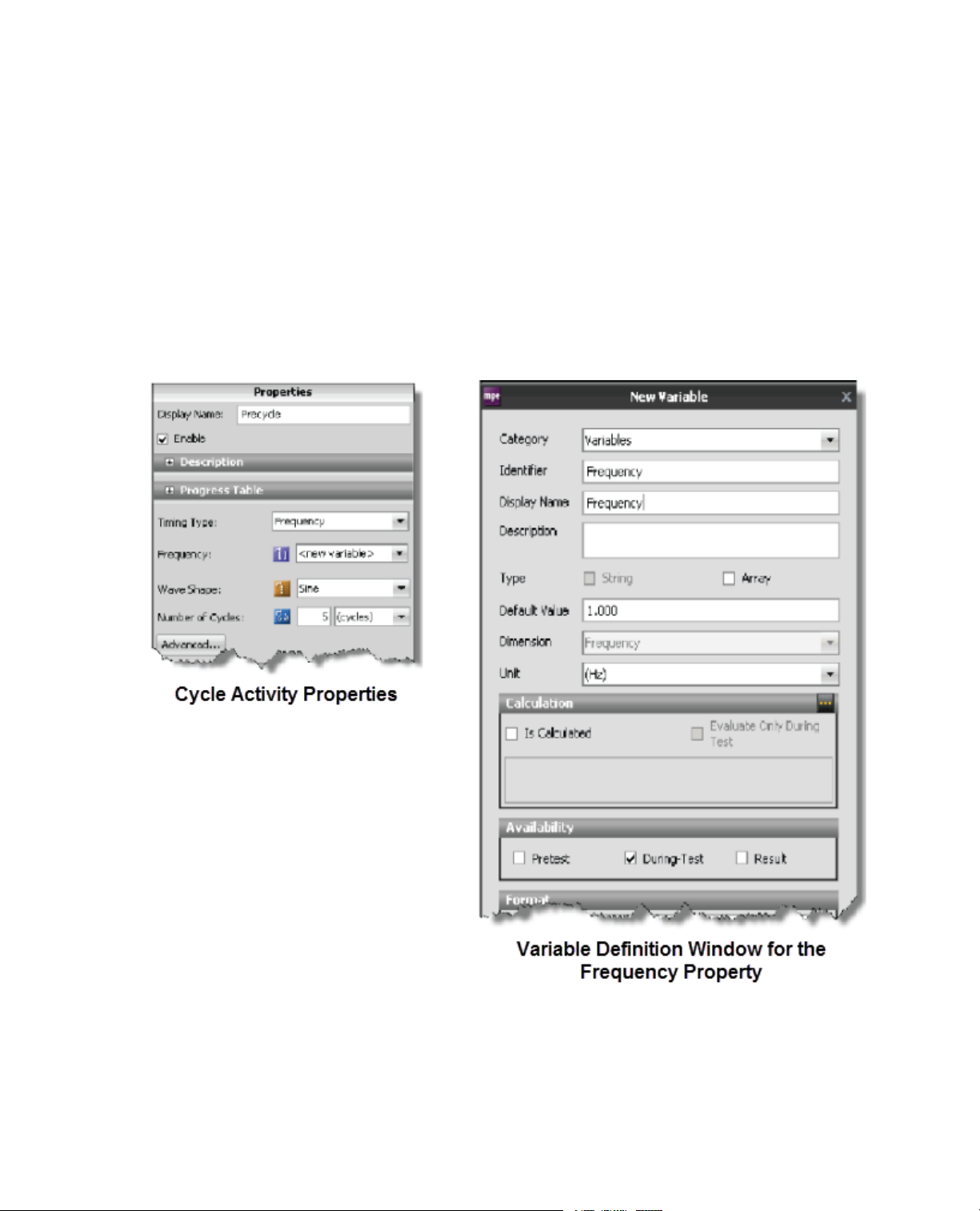
Test activity property definition
To define the properties of an activity, select the activity icon on the Procedure tab, and then click the
Properties tab.Y ou can choose to define properties as fixed v alues or variable v alues.The following example
shows the property definitions for a Cycle test activity.
Multipurpose Elite Test Design Guide 19
Page 20
3.0 Designing a Test
Cycle Activities Properties
Error indicators assist definition
Red error icons appear next to activity property fields where information is missing or incorrect.
20 Multipurpose Elite Test Design Guide
Page 21
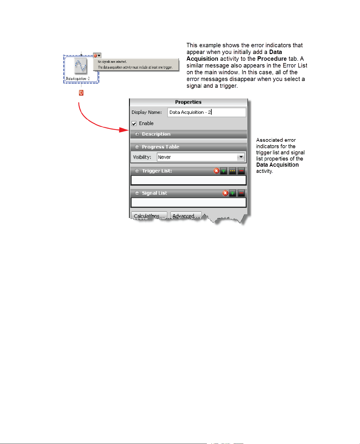
3.0 Designing a Test
Error Indicators
3.2.3.1.0 Deleting and Disabling Test Activities
If you want to remove a test activity from the test procedure, you can either delete the test activity or disable
the test activity.
When you delete the activity, the activity is permanently removed from the test procedure.This action cannot
be undone, and you will have to either recreate the test activity or revert to a previously-saved v ersion of the
test that contains the activity.
If you do not want to delete a test activity, but you also w ant to temporarily pre v ent the activity from occurring
during a test run, you can disable the activity.When you disable a test activity, the test activity becomes
gray ed-out in the test procedure and the activity is ignored when the test is run. After you disable an activity,
you can enable the activity and it will once again occur during test runs.
You may find it helpful to temporarily disable some test activities when you are creating a test or when you
are troubleshooting suspected problems in the test. For example, y ou can disab le certain portions of the test
in order to focus your time on a f ew specific test activities that y ou believ e are causing problems. Alternatively ,
if you want to remove a troublesome test activity, but you are unsure of the impacts, you can temporarily
disable that test activity and replace it with a modified activity and perform a test run to view the results. If
you determine that you do need the disabled test activity, you can later "retriev e" the test activity b y enabling
it.
To delete, disable, or enable a test activity, right-click the test activity and select Delete, Disable, or Enable
(if the test activity is currently disabled).
Multipurpose Elite Test Design Guide 21
Page 22
3.0 Designing a Test
3.2.3.2.0 Variables Overview
Typically, when you enter a value for a property in an activity, you can change the value only when the test
is stopped and the test procedure is unlocked. In this sense, the property is “fixed.”
With the use of variables, you can associate a property of an activity with a variable .This allows you to change
the variable value without selecting the activity.
For example, suppose you create a test procedure that includes several command activities that all use the
same frequency. Rather than enter a frequency value for each activity separately , y ou could associate all the
frequency properties with a “Frequency” variable.Then, between tests (with the test stopped and the test
procedure unlocked), you could use the Variables Editor to change the frequency value of all the activities
at the same time. For more information about the Variables Editor, see the Multipurpose Elite User Guide.
The following example shows how to make the Frequency property of the Cycle activity a variable.
Cycle Activity New Variable
Variable use in MTS TestSuite software
MTS TestSuite software uses variables extensively throughout its applications:
22 Multipurpose Elite Test Design Guide
Page 23

3.0 Designing a Test
• The MPE application uses variables to simplify test creation and modification, allow operator interaction
in the test flow, and facilitate monitor display.
• The MTS TestSuite Reporter Add-In for Microsoft Excel uses variab les to capture test data for test reports.
• The various MTS Analyzer applications use variables to create “what if” scenarios using specimen variables
and data from test runs.
Test activities and variables
The MPE application allows you to define many of the individual properties of test activities as variables.The
MPE application also includes test activities you can use to manipulate variables in the test flow, as follows:
• Assign Variables activity
• Calculate Variables activity
• Input Parameters activity
You can use these activities in a variety of wa ys to manipulate variables. For example, you can use an Input
Parameters activity to allow the operator to change variable values while the test is running.
Adding calculations to variables
You can add mathematical operators to variables to create calculated variables.You can do this in two ways,
depending on test design considerations:
• Click the Variables tab in the main window to add calculations to individual variables.
• Add the Calculate Variables activity to the test procedure.This activity allows you to add calculations to
variables in the test flow.
Adding and editing variables
You can add or edit variables from within the various variable editing windows and editors (such as the Map
Variables window or the Calculation Editor).You can click the Add Variable (green plus sign) or Edit Variable
(...) icon or right-click and select New Variable.To edit a variable, right-click a variable name and select Edit
Variable.
3.2.3.3.0 Information for an Operator
You can add information for an operator, such as hardware installation instructions or safety information,
directly into your test design.This allows you to create the inf ormation visible to the operator during the test,
and control at which point in the test flow to show the information.
To do this, add special test activities and run-time devices to your test.
• The Custom Message Window activity allows you to show a custom message to the operator anytime
the test is running.
• The Run External Application activity allows you to show documents that require external applications
to launch, such as word processing, spreadsheet, and video documents.
• The Custom Help monitor display allows you to show custom help information, such as files in the .chm
file format, that you create for the test.
Multipurpose Elite Test Design Guide 23
Page 24
3.0 Designing a Test
3.2.4.0 Working with Test-Run Display Devices
When you start the test, you can see real-time test information on the Test-Run Display panel.
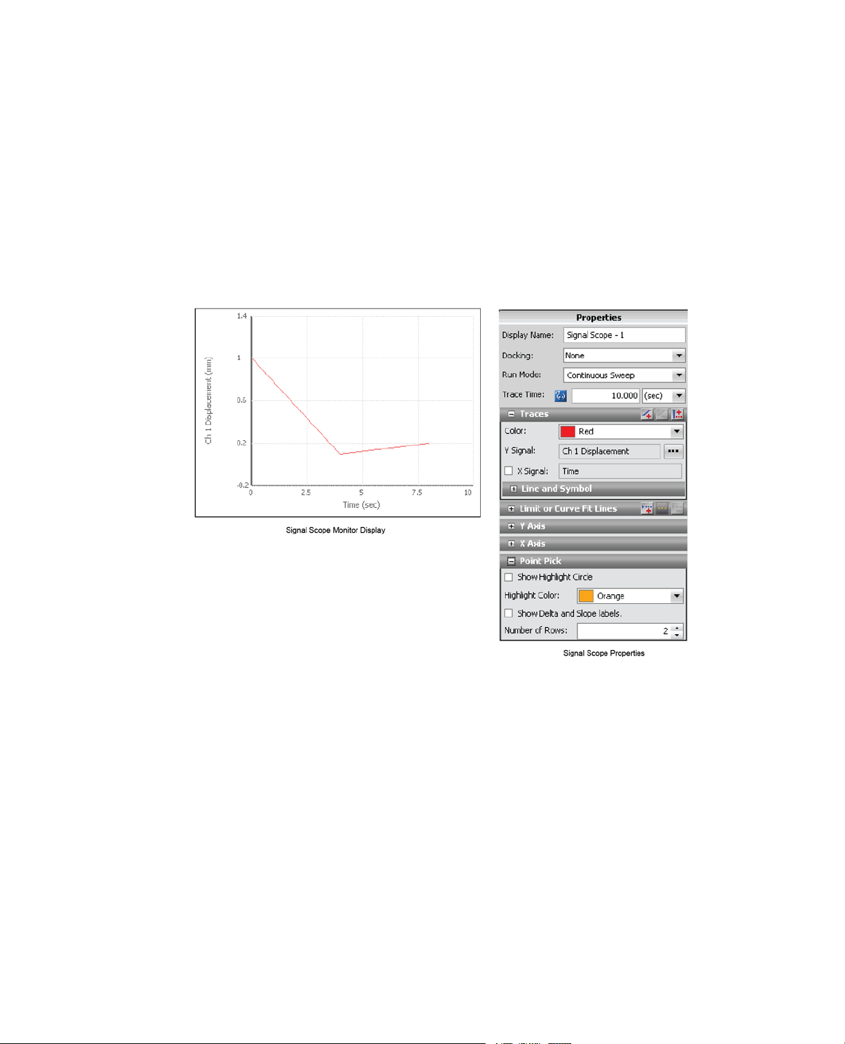
Add monitor display devices
To add monitor display devices to y our test, clic k the Test-Run Display tab and drag monitor display de vices
from the toolbox to the work area.When you do this, error icons on the device icon and Error list guide you
to define required properties.The following example shows a Signal Scope device, which simulates an
oscilloscope on the Test-Run Display tab when the test executes.To view its properties, you select the
Signal Scope device on the work area.
Signal Scope Monitor Display
3.2.5.0 Test Execution Overview
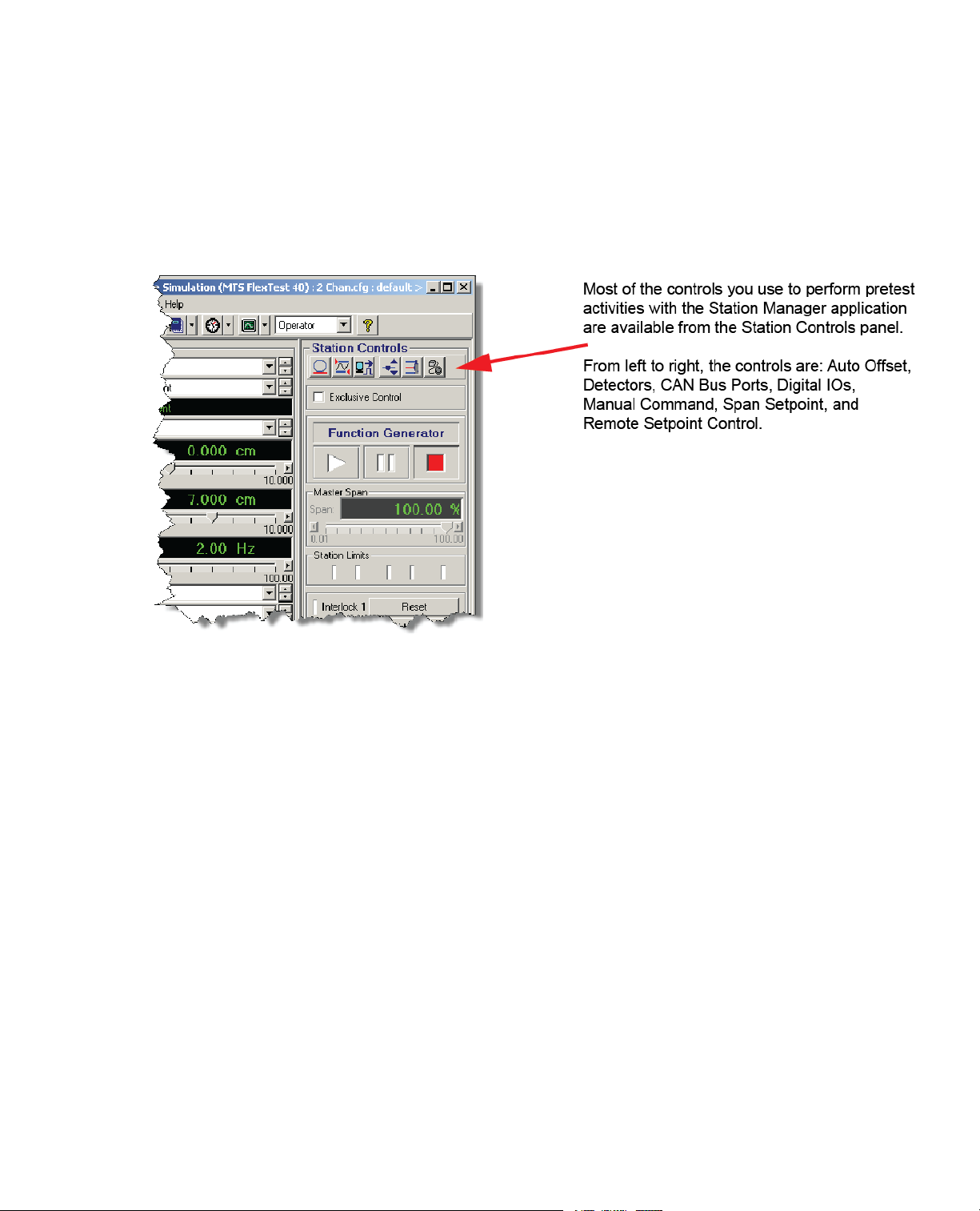
Using Station Manager with TestSuite software
The Station Manager application runs in the background alongside the MPE application.When you design
or run tests with the MPE application, minimize the Station Manager application to simplify your PC desktop.
The activities that an expert user may perform with the Station Manager application varies with your station
and test setup, but typically includes:
• Design and use profiles.This is done using the optional Profile Editor in the Station Manager application.
• Install new hardware resources.This is done using the Station Builder tool in the Station Manager
application.
24 Multipurpose Elite Test Design Guide
Page 25
3.0 Designing a Test
• Adjust commands settings (such as ramp and taper times).This is done using the Channel Options tool
in the Station Manager application.
• Access the values of calculation parameters and variables.This is done using the Calculation Editor in
the Station Manager applicationr.
• Set limit levels and actions for detectors.
• Position the actuator to install the specimen.
• Apply offsets.
MTS Station Manager Window
Station activities you can perform with the Multipurpose application
You can perform some station activities with the Multipurpose application, such as:
• Energize and de-energize actuator power.
• Reset and override interlocks.
• Start, hold, and stop tests.
• Perform Park, Unload, and Stop At operations.
Other station activities you may perform with Station Manager
You can perform some station activities pre-test or between tests, such as:
• Check shunt calibration levels
• Adjust tuning values
You can only perform these activities with the Station Manager application.
Multipurpose Elite Test Design Guide 25
Page 26
3.0 Designing a Test
Test execution with the MPX application
Similar to the MPE application, the MPX application can be used to run tests. However , the MPX application
cannot create or modify tests. In order to create or modify tests, you must use the MPE application.
Considerations for automatic background saves
It is important to keep in mind that when you start a test run, the application automatically saves the current
state of the test. If you need to modify a test without necessarily saving your changes; that is, experiment
with the test, you should perform a Save As of your test, modify as required, and then run the new test.
If you inadvertently run a modified test and have to undo the changes you made to the test before you ran it
(and the application automatically saved it), you must do so manually.
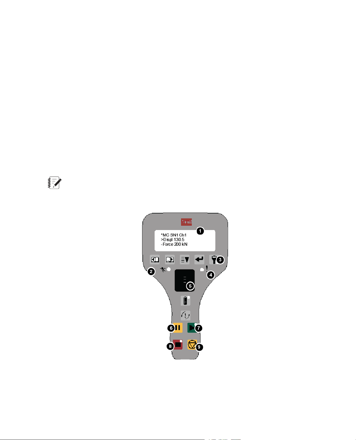
3.2.6.0 Model 494.05 Handset Station Activities
If your station is equipped with a Model 494.05 Handset, you can use it to:
• Manually position the actuator to install the specimen.
• Apply offsets.
Note:
You cannot use the handset to set limit levels and actions for detectors. Perform these activities with
the MTS Station Manager application.
26 Multipurpose Elite Test Design Guide
Model 494.05 Handset
Page 27

3.0 Designing a Test
Note:When control is provided by a handset, the application controls will be locked and overlaid by
the handset exclusive control icon:
Description of Model 494.05 Handset
DescriptionItem
Programmable display1
Hydraulics indicator2
Exclusive control3
Interlock indicators4
Thumbwheel (manually positions the actuator when Manual Command is enabled)5
Manual command6
Interlock reset/override7
Program Run/Stop/Hold controls8
Hydraulics off9
3.2.7.0 Generating a Report in MP
To generate reports from within MP, you must have an existing report template and the Microsoft Excel
application or a suitable Microsoft Excel reader. To design or modify a report template, you must have the
Reporter Add-In application, which is a separately licensed product.
1. On the Explorer panel, right-click the Test Run name and select Generate Report.To generate multiple
reports at one time, click Test Runs on the Explorer panel to see the Test Runs table. Select the test
runs to include in the reports.To select more than one, press the Ctrl key and click the report name.
Right-click and select Generate Report.The Generate Report window opens.
2. Select one or more templates to use for your reports and click Generate Report.
3. Microsoft Excel opens with the newly generated report. If multiple test runs were selected, a separate
report for each Test Run will open. Modify as desired and save and close. By default, the report is shown
below the test run name in the Explorer panel.You can click Preferences > Configuration and select
a different location for generated reports on the Project tab.
Multipurpose Elite Test Design Guide 27
Page 28

3.0 Designing a Test
3.2.8.0 Generating a Report Using the Excel Reporter Add-In
Note:
To generate a report using the Excel Reporter Add-In, you must have purchased a separate license
for the Reporter Add-In product. It also requires the installation of Microsoft Excel software or another
suitable Microsoft Excel reader.
1. Open a report template in Excel (MTS templates are located in C:\MTS TestSuite\Report Templates).
2. Click the MTS TestSuite Report tab in the ribbon.
3. Click the Test icon in the ribbon and open the test that contains the test run that requires a report.
4. In the Generate section of the ribbon, click Source and select the test, test run, or analysis run that you
want to use to create a report.
5. Click the Report icon on the ribbon.
6. The system will launch another instance of Microsoft Excel and show the newly generated report file.
28 Multipurpose Elite Test Design Guide
Page 29

4.0 Working with Resources
Topics:
•
Resources..............................................................................................................................................30
•
Starting MPE and Connecting to a Controller........................................................................................30
•
Station Configurations...........................................................................................................................32
•
Controller Resources.............................................................................................................................32
•
Resource Mapping.................................................................................................................................33
•
Offline Test Design.................................................................................................................................34
•
Resources That Allow Dimension Changes..........................................................................................36
Multipurpose Elite Test Design Guide 29
Page 30

4.0 Working with Resources
4.1.0 Resources
With the MPE application, you create test designs that cause controller resources to apply desired forces to
your test specimen. Controller resources include control channels, control modes, sensors , digital inputs, and
so on.
For example , suppose you design a test to apply a tensile force to your specimen and receive a digital pulse
when the specimen fails.When you run the test, the controller uses a control channel with a force control
mode resource to apply the tensile force to the specimen, and a digital input resource to receive the digital
pulse.
Controller resources
A controller resource refers to a hardware resource in the controller as it appears in a station configuration
file. For example, a control mode in a station configuration file named “axial force” is a controller resource.
Test resources
A test resource refers to a resource with equivalent functionality as it appears in the test definition. For
example, a control mode in a test definition named “load 1” is a test resource.You can use test resources
for various test elements, such as activities, monitor display devices, and variables.
Resource mapping
A test resource is not required to have the same name as the equivalent controller resource. However, if the
names are different when the MPE connects to the station, you must map the test resource to the equiv alent
controller resource.
For example , suppose you design a test offline in which you name a control mode “load 1”. Later , y ou connect
to a station in which the equivalent resource is named “Axial Force”.This mismatch of resources creates a
resource validation error. To resolve this error, you must map the test resource to the controller resource.
4.2.0 Starting MPE and Connecting to a Controller
Controller resources are available to the MPE application through station configur ation files . Before you start
the MPE application, you typically start the MTS Station Manager application and open a station configuration
file first.When you start the MPE application, it automatically connects to the station configuration, which
allows you to design tests with the resources in the station configuration. If you do not already have one, y ou
can create a desktop shortcut that will open the MTS Station Manager application and then open the MPE
application. F or more information about creating that shortcut, see Creating a Desktop Shortcut That Includes
a Controller on page 18.
30 Multipurpose Elite Test Design Guide
Page 31

Display of MPE Application Resources
DescriptionFunctionNumber
4.0 Working with Resources
1
2
Controller and Station
Identification
Resources Tab
Access
Test Resources3
Controller Resources4
When MPE is connected to a station, the window title
shows the controller and station configuration
associated with the current test. In this example, the
controller name is “MTS FlexTest 40”, and the station
configuration name is “2 chan.cfg”.
On Explorer, clic k Resources. Clic k a Test Definition
element and click the Resources tab at the top of
the panel.
The resources in the Name column are test
resources.Test resources are required by the test
and must map to equivalent resources in the
Controller Resources column when connected to a
controller.
Controller resources represent hardware resources
in the physical station. Resource mapping is saved
with tests.
When connected to a controller, Controller Resources
reflect the resources in the Station Configuration file.
When not connected to a controller, Controller
Resources reflect the resources the MPE application
expects to find when connected to a station.
For More Information
Offline Test Design on page 34
Multipurpose Elite Test Design Guide 31
Page 32

4.0 Working with Resources
4.3.0 Station Configurations
A station configuration is a discrete file that lists all or a portion of the hardware resources in your physical
station.You create and modify station configurations with the MTS Series 793 controller software. MTS
typically provides a station configuration when you receive your system.
Station Configuration
The Station Configuration file lists some or all of the hardware resources in your test system.When you
connect to a controller with MPE, the Controller Resources shown on the Resources tab are the same as
the resources in the station configuration file.
4.4.0 Controller Resources
A station configuration may include only a portion of the resources available to the controller.The complete
inventory of resources availab le to your controller is defined by the hardw are interface file (or .hwi file) installed
with your controller software.The .hwi file defines what internal components are available to your controller,
which controller slots they are installed in, and which rear-panel connectors they are accessed through.
32 Multipurpose Elite Test Design Guide
Hardware Interface File
Page 33

4.0 Working with Resources
The Hardware Interface file represents all of the hardware resources available to your test system.When
you connect to a station with MPE, the Controller Resources shown on the Resources tab pertain only to
the connected controller.
Note:
You use the Station Builder application (one of the applications included with MTS Series 793 controller
software) to define station configuration files by allocating some or all of the resources listed in the .hwi
file.
4.5.0 Resource Mapping
A resource map aligns test resources with controller resources.When you create a test while MPE is connected
to a controller and save the test, MPE saves the resource map with the test definition.The resource map
saved in the test definition is an inventory of resources the MPE application expects to find the next time it
connects to a controller.
Before you can load and run the test procedure on a controller , the test resources must either be automatically
or manually mapped to controller resources. Resources are stored with the test definition and validated against
the available controller resources the next time the application connects to a controller.
Automatic mapping example
Suppose you design a test online while MPE is connected to a controller. As part of your test, you add a
Ramp activity and select a control channel named “Ch 1” and a control mode named “Displacement”.When
you design a test online rather than offline, you are using the test resources that MPE automatically mapped
to the controller when MPE connected to the controller.When you save the test, the names for all of the test
resources in the test definition appear identical to the equivalent controller resources on the Resources tab.
If you disconnect the controller from your test, MPE expects to find the same controller resources for the
current test in whatever station you connect to in the future.
If you reconnect to the same controller, MPE maps the channel and control mode test resources to the
equivalent resources in the controller, and you can run the test immediately.
If you reconnect to a different controller, one of two things may occur:
• If MPE finds a control channel named “Ch 1” and a control mode named “Displacement” in the station
with equivalent functionality , then MPE automatically maps them to the test resources with the same name .
If the remainder of the test resources also map to the controller resources in the new controller, you can
run the test immediately.
• If MPE does not find a control channel named “Ch 1” and a control mode named “Displacement” in the
station, it shows validation error icons.You must resolve these errors (and any other validation errors)
before you can run the test.
Manual mapping example
Suppose you design a test while MPE is connected to a controller , and that the controller has control modes
named “Disp 1” and “Load 1”. Now, suppose you disconnect from the controller and connect to a different
controller that has control modes named “Displacement” and “Force”.
Multipurpose Elite Test Design Guide 33
Page 34

4.0 Working with Resources
In this case, MPE is unable to automatically map the new controller resources to the test resources, and
shows validation error icons.To resolve the errors, you must manually map the controller resources to the
test, as shown.
Resource Validation Errors
Resource validation errors appear as red icons on the Resources tab.Validation errors occur when you
connect to a controller and MPE cannot locate controller resources that match test resource requirements in
the test definition. In this example, the names of the test resource control modes are “Disp 1” and “Load 1”.
If resources exist in the connected controller that have equivalent functionality but different names, you can
map them to the current test.To remap a resource, click the list icons in the Controller Resource column that
contains error icons and select compatible resources.
Import resources from an existing test
Before you begin manually entering test resource names, chec k to see if any other tests e xist that ha v e been
designed with the controller to which you intend to connect. If there are, import the resources from that test
first to save time. (Resources tab > Import Resources > Import resources from another test.)
4.6.0 Offline Test Design
You can design tests offline, that is, when disconnected from the controller and away from the station, and
then map resources when you connect to the station.You might find offline test design useful if you want to
design tests in your office or anywhere else outside of the lab .When you design tests offline, you do not have
to start the Station Manager application and open a station configuration before starting the MPE application.
The general workflow for designing tests offline is as follows:
1. Start the MPE application without starting the Station Manager application or connecting to a controller.
2. Click the Resources tab.
3. Manually enter test resource names.
4. Assign the test resources you created to test elements (such as activities, variables, and so forth).
5. Save the test.
6. Connect to a station.
7. Manually map the resources in the station to your test.
34 Multipurpose Elite Test Design Guide
Page 35

4.0 Working with Resources
Creating resources manually
If no existing tests are av ailable to import resources from, you must add them to your test manually. (Resources
tab > Add Resource > resource type).When you add a resource, you must enter a Display Name, an
Internal Name (spaces not permitted), and where applicable, a Dimension.
Example of Control Mode Test Resources Added Manually
Mapping test resources that have been added manually to controllers
When you connect to a station, MPE attempts to map the test resources you added offline to the station. If
the resource names do not match, MPE shows resource validation errors.To resolve the errors, you must
manually map the controller resources to the test. For more information about mapping controller resources
to the test, see Resource Mapping on page 33.
Considerations for selecting compensators
It is a best practice to wait until you connect to a station bef ore selecting compensators for command activities.
When not connected to a station, the compensator list for a given command-type activity shows all of the
types of compensators that are possible to use with the activity.When you connect to a station, the list of
compensators shows only the compensators that are actually available to the activity.
When connected to a station, compensator availability is affected by the following:
• Some compensators apply only to specific types of command activities. For instance, Peak Valley
Compensation (PVC) pertains only to cyclic command.
• Some compensators, such as Adaptive Inverse Control (AIC), are licensed and are only available if they
were purchased.
• Some compensators, such as Null Pacing, are available only if they are enabled in the underlying station
configuration.
For More Information
Resource Mapping on page 33
Multipurpose Elite Test Design Guide 35
Page 36

4.0 Working with Resources
4.7.0 Resources That Allow Dimension Changes
Float signals with fixed dimensions
A float signal is a type of test resource that typically has a fixed dimension assignment. An example of a float
signal is “Ch 1 Displacement” with a dimension of “Length”.
Float signals with dynamic dimensions
Some float signals can change their dimension during the test:
• Channel Command
• Channel Comp. Cmd
• Channel Active Fdbk
• Channel Error
• Channel Active Stabilization
Float signals that can change their dimension have a dimension type of “<Dynamic>”.
Using the <Dynamic> dimension type in tests
When designing tests, you typically use these signals with the Signal Scope.This allows you to view controller
signals that change dimension during the test, such as when the control mode changes. (Test-Run Display
> Signal > Signal Scope).
You cannot use these signals for functions that cannot tolerate dimension changes while the test is in prog ress,
such as data acquisition, limit detectors, and so on.
36 Multipurpose Elite Test Design Guide
Page 37

5.0 Creating Tests
Topics:
•
Installing MTS TestSuite Simulation Software.......................................................................................38
•
Creating Ramp and Cycle Test..............................................................................................................38
•
External Commands..............................................................................................................................55
•
External Command Considerations.......................................................................................................69
Multipurpose Elite Test Design Guide 37
Page 38

5.0 Creating Tests
5.1.0 Installing MTS TestSuite Simulation Software
Installation of the simulation software consists of launching two separate self-e xtr acting executables, one for
the MTS TestSuite application and one f or the MTS Series 793 Simulation software .These files are available
on CD-ROMs or download sites.
MTS TestSuite self-extracting executable
This file installs any of the following MTS TestSuite applications that you have purchased a license for:
• Multipurpose Elite (mpe), for designing and running tests
• Multipurpose Express (mpx), for running tests
• Fatigue Analyzer (faa), for analysis of fatigue test data
• Fracture Analyzer (fra), for analysis of fracture test data
Series 793 Simulation self-extracting executable
This file installs a simulated version of MTS Series 793 software, including configuration and support files
used with this guide.This software provides simulated real-time control of a test station.
Installation procedure
For detailed instructions on how to install simulated testing software, see the Multipurpose Elite Simulated
Testing User Guide.
A PDF of this document is available in the following locations:
• As a link on the MTS TestSuite Multipurpose Software self-extracting executable
• From the Windows Start button after the MTS TestSuite Multipurpose software is installed (Start >
Programs > MTS TestSuite > Documentation)
The same information is also available in the online help for the Multipurpose Elite application.
5.2.0 Creating Ramp and Cycle Test
5.2.1.0 Ramp and Cycle Test Design Overview
This section contains a walkthrough of how to create a simple test using MTS TestSuite MPE that ramps and
cycles the actuator.The Ramp and Cycle test design performs the following activities:
• Ramps from zero to a fixed mean level.
• Cycles at an amplitude relative to mean as entered by the operator.
38 Multipurpose Elite Test Design Guide
Page 39

5.0 Creating Tests
• Acquires time data while cycling.
• Ramps back to zero.
• Shows test signals on a Signal Scope monitor as the test runs.
After you follow the steps in this chapter, the Ramp and Cycle test appears in the Procedure workspace as
follows:
Ramp and Cycle Test
When you run the ramp and cycle test, the Signal Scope monitor will show the following test results:
Multipurpose Elite Test Design Guide 39
Page 40

5.0 Creating Tests
MPE features used to create this test
• Ramp activity
• Cycle activity
• Data Acquisition activity
• Input Parameters activity
• Parallel Path activity
• Relative End Levels property
• Variable properties
• Signal Scope monitor display
5.2.2.0 Opening a Station Configuration and Starting the MPE Application
Use this task to open a station configuration file (or station) with the Station Manager application, and then
start the MPE application.The Station Manager application is a component of your MTS controller software,
which performs real-time control when you run tests.The test procedures that you create with the MPE
application manipulate resources in the station to apply forces to the physical specimen.
Note:
The instructions in this section are intended to be performed in simulation mode. See Installing MTS
TestSuite Simulation Software on page 38.
1. Click the Windows Start button on your desktop and select Programs > MTS 793 Software > Station
Manager.
40 Multipurpose Elite Test Design Guide
Page 41

5.0 Creating Tests
Note:
If you are prompted to select a controller, select the MTS FlexTest 40 controller.
2. In the Open Station window, select the “2 Chan.cfg” configuration file and then click Open.
Note:
The controller and configuration file you selected in the previous two steps are used for creating
and running tests using the simulation and this test design guide.When you use other stations
connected to actual systems, you may need to select other controllers or configur ation files tailored
to the station that you are working with.
3. Minimize the Station Manager window.You do not have to access the Station Manager application while
creating this test.
Note:
When you run tests on physical specimens (not in simulation mode), you typically use the Station
Manager application to perform tasks such as setting limits, installing the specimen, and so on. See
MTS Controller Software on page 95.
4. Click the Windows Start button on your desktop and select Pr ograms > MTS TestSuite > Multipurpose
Elite.
For More Information
Installing MTS TestSuite Simulation Software on page 38
MTS Controller Software on page 95
5.2.3.0 Creating an Empty Test
Use this task to create an "empty" test and open the Procedure workspace. An empty test is a test that was
not created using a template.There, almost all components of the test, including the test procedure and
variables, are not established.
Note:
The MPE application typically offers more than one method to select existing or create new test files.
You can click toolbar icons, make menu selections, or use the right-click menu.
1. On the toolbar, click the New Test icon arrow and select the New Test option.
2. In the Explorer panel, click Procedure.The Procedure workspace is shown.
3. In the Procedure workspace, observe the green “start” and red “stop” icons between which activities are
placed.
4. On the toolbar, click the Save icon and rename your test as desired.
5.2.4.0 Adding a Ramp Activity
Use this task to add a Ramp activity to the procedure and define its properties. During the test, the Ramp
activity causes the command to ramp to the specified mean level.
Multipurpose Elite Test Design Guide 41
Page 42

5.0 Creating Tests
Note:
Some of the property values you need to enter for this sample test may already be present as default
values.
1. Click on the Procedure tab, and scroll to the Ramp activity in the Toolbox list.
2. Drag and drop the Ramp activity on the “Drop Activities Here” text in the work area.
3. Define Ramp activity properties:
a. Enter the following values as necessary:
Ramp Activity Properties
ValueProperty
Ramp to MeanDisplay Name
TimeTiming Type
2 secTime
RampRamp Shape
No CompensatorCompensator
Ch 1Channel List
DisplacementControl Mode
Adding a Ramp Activity
4 mmAbsolute End Level
42 Multipurpose Elite Test Design Guide
Page 43

5.0 Creating Tests
5.2.5.0 Adding a Cycle Activity
Use this task to add a Cycle activity to the procedure and define its properties. During the test, the Cycle
activity applies a sinusoidal command relative to the mean level.
1. Drag a Cycle activity below the Ramp activity.
2. Define Cycle activity properties:
a. Ensure that the Cycle activity is selected.
b. Enter the following values as necessary:
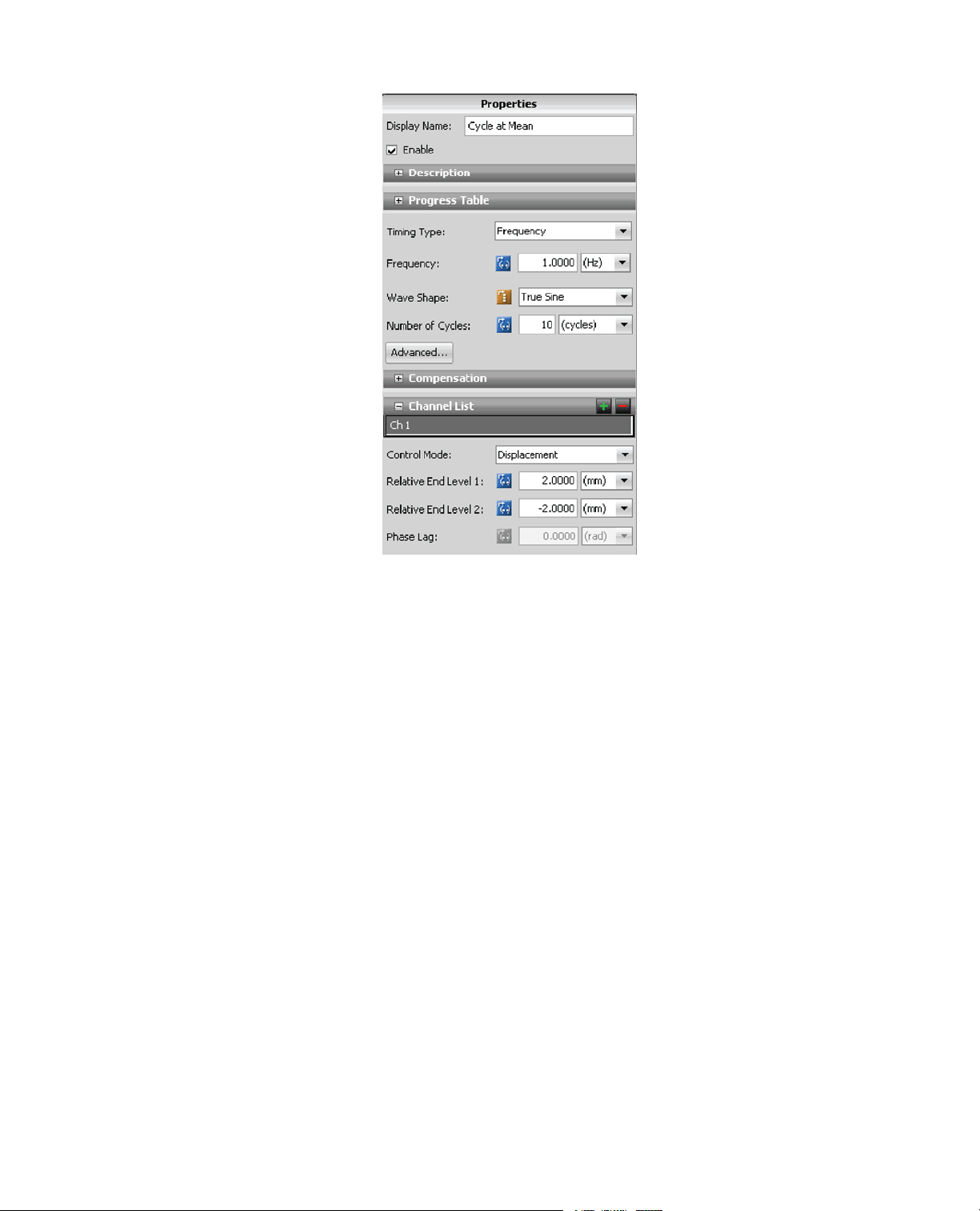
Cycle Activity Properties
ValueProperty
Cycle at MeanDisplay Name
FrequencyTiming Type
1 HzFrequency
True SineWave Shape
5Number of Cycles
Interrupt ImmediatelyAdvanced...
Relative End Levels
Adding a Cycle Activity
Multipurpose Elite Test Design Guide 43
Page 44

5.0 Creating Tests
ValueProperty
No CompensatorCompensator
Ch 1Channel List
DisplacementControl Mode
2 mmRelative End Level 1
-2 mmRelative End Level 2
N/APhase Lag
5.2.6.0 Adding a Second Ramp Activity
Use this task to add a second Ramp activity to the procedure. During the test, the second Ramp activity
ramps command to zero.
1. On the Procedure workspace, right-click the existing Ramp activity and select Copy.Then, right-click
below the Cycle activity and select Paste.
Copying and Pasting Existing Ramp Activity
2. Define Ramp activity properties:
a. Ensure that the Ramp activity is selected.
b. Enter the following as necessary:
44 Multipurpose Elite Test Design Guide
Page 45

Second Ramp Activity Properties
ValueProperty
Return to ZeroDisplay Name
TimeTiming Type
2 secTime
RampRamp Shape
No CompensatorCompensator
Ch 1Channel List
DisplacementControl Mode
0 mmAbsolute End Level
5.0 Creating Tests
5.2.7.0 Adding a Signal Scope Monitor
In this task, you add a Signal Scope to the test.The Signal Scope is graphical, real-time display of your test
data.When running the test, the Signal Scope simulates a conventional oscilloscope.The MPE application
requires defining at least one monitor display before you can run the test.
1. Click the Test-Run Display tab.
2. In the Toolbox panel, note the various monitor displays available.
3. From the Signal list, drag the Signal Scope icon to the Designer area. Position the displa y graph as desired.
4. Observe the Error icons on the Signal Scope, in the Properties panel, and in the Error list at the bottom
of the screen (you may need to expand the panel).The errors direct you to define a parameter for the Y
axis of the Signal Scope.
5. If necessary, click to expand the Traces panel.Then click the (...) icon next to the Y Signal property.
Multipurpose Elite Test Design Guide 45
Page 46

5.0 Creating Tests
6. Select Ch 1 Displacement and click OK.
Note:
By default, Time is the parameter used for the X axis, which is desired for the sample test.
Selecting a Y Signal
7. In the Properties panel, expand the Y Axis panel.
8. Select the Maximum check box.
9. Set the Maximum value to 12 mm.This accommodates the amplitude of the end-level values of the Cycle
at Mean activity.
Setting the Y Axis Maximum
46 Multipurpose Elite Test Design Guide
Page 47

5.0 Creating Tests
Signal Scope Monitor with 12 mm Y Axis Maximum
10. Click the Preview subtab inside the Test-Run Displa y tab to view an example of the Signal Scope monitor
display.
5.2.8.0 Checking the Test Procedure
In this task, you run the test to check its design thus far.
Note:
The test design process is iterative; therefore, it is a recommended best practice to build your test
procedure incrementally.
1. Ensure that the station has power. Access the Hydraulic Power Unit (HPU) by clicking the arrow in the
lower right corner of the Power pane. Set the HPU to high. If the interlock indicator appears red on the
System panel, click Reset. Ne xt, turn on the Hydraulic Service Manifold by clicking the P o wer Low b utton
and then the Power High button on the Power panel.
2. Next, click the New Test Run icon found in the tool bar.
3. Observe the Specimen Selection window .This window pertains to the physical characteristics of your test
sample. Because this is a new test and no specimens used in prior test runs are available, select a new
specimen by clicking the Add New Item (+) icon.
4. Observe the new specimen selection with the following properties:
Specimen Selection Properties
ValueProperty
Specimen-1Name
GenericGeometry
Multipurpose Elite Test Design Guide 47
Page 48

5.0 Creating Tests
ValueProperty
GenericDomain
5. Click OK.
6. Observe the Setup Variables window, and click OK.
7. Observe the Signal Scope.The test is not running yet, so the signal trace is flat.
8. To start the test, click the Run button (green arrow) on the Test control panel.
9. Observe the test run on the Signal Scope.The signal trace ramps to a mean level of 4 mm, performs five
cycles with a true sine waveshape to relative end levels of 6 mm and 2 mm, and returns to zero.
Test Run on Signal Scope
5.2.9.0 Adding Variables
In this task, you replace the currently fixed end-level values of the Cycle activity with variable values. After
you define an Input Parameters activity, the operator can enter variable values that define the cycle end
levels before running the test.
1. Click the Procedure tab.
2. Click the Cycle activity in the Toolbox panel.
3. Observe the Relative End Level 1 property. Note that the current value is 2 mm, and the icon directly to
the right of the Relative End Level 1 label contains parentheses.
48 Multipurpose Elite Test Design Guide
Page 49

5.0 Creating Tests
Relative End Level 1 with a Non-Variable Value
4. Click the icon and observe that it toggles (changes) its appearance.The Variable icon contains empty
brackets. Also, note that the property value (2 mm) has cleared.The property is now ready to be assigned
to a variable.
Relative End Level 1 Ready for Variable
5. Click the Relative End Level 1 entry box and select <new variable>.
Note:
If a preexisting variable w as availab le for this property , it w ould appear in the list with <new variab le>.
6. Observe the New Numeric Variable window, and enter the following as necessary:
New Numeric Variable Window Properties
NotesValueProperty
VariablesCategory
EndLevel1Identifier
End Level 1Display Name
This is the internal name of the variable.
It cannot contain spaces.
This is the name as it appears in variable
lists.The application creates it from the
label name and adds spaces where
appropriate.You can rename the Display
Name as desired.
Multipurpose Elite Test Design Guide 49
Page 50

5.0 Creating Tests
NotesValueProperty
NoneDescription
NumberType
LengthDimension
mmUnit
2.00Default Value
DisabledCalculation
During TestAvailability
FixedFormat Type
DecimalDigit Type
3Digits
This sets the initial value of End Level 1
to 2 mm, which is the same value you
entered on the Properties tab when you
originally defined the Cycle activity.
However, now the End Level 1 value
changes whenever the operator changes
the variable value.
You provide the operator the capability
to change the variable value while the
test is running by enabling the Editable
During Test property, and adding the
Input Parameters activity.
This allows the variable value to change
during the test (when the test is locked).
DisabledUse Range
7. Click OK.
8. Follow the method used to create End Level 1 and create a variable for End Level 2 with a default value
of -2 mm.
Note:
If you were to run the test now, it would look identical to the previous run because you assigned
default values to the variables that are identical to the originally assigned values.
5.2.10.0 Adding an Input Variables Activity
In this task, you add an Input Variables activity to the procedure and define its properties. During the test,
the Input Variables activity opens a window that allows the operator to change the end levels of the Cycle
activity.The end levels are variable values an operator can change before running the test.
50 Multipurpose Elite Test Design Guide
Page 51

5.0 Creating Tests
1. Click the Procedure tab and scroll to the Operator Entry category in the Toolbox panel.
2. Drag the Input Variables activity to the Procedure workspace and place it before the topmost Ramp
activity.
Test Procedure with New Input Variables Activity
3. In the Properties panel, enter the following as necessary:
Input Variables Activity Properties
ValueProperty
Enter Relative Cycle End LevelsDisplay Name
Message
Variable List Note:
Enter End Level 1 and End Level 2 values for the
Cycle activity, then click OK.
Click the plus sign and use the Variable
Selection window to add variables.
End Level 1, End Level 2
NoneRules
DisabledAdd Cancel Button
Multipurpose Elite Test Design Guide 51
Page 52

5.0 Creating Tests
5.2.11.0 Adding Parallel Paths and a Data Acquisition Activity
Use this task to add parallel paths to the procedure. Parallel paths allow concurrent test activities, which in
this task are the Cycle and Data Acquisition activities. F or this ex ercise, you mov e the existingCycle activity
within the parallel path, add a Data Acquisition activity, and designate the terminal path.The terminal path
determines when all other paths terminate. During the test, the parallel paths definition causes the test to
acquire data when the Cycle activity starts running.
1. Add a Parallel Paths activity to the test flow.
a) Click the Procedure tab and scroll down to the Test Flow Control category in the Toolbox panel.
b) Drag the Parallel Paths activity icon to the Procedure workspace and drop it after the first Ramp
activity.
Test Procedure with New Parallel Paths Activity
2. Name each path in the Parallel Paths activity.
a) In the Parallel Paths container, click the path branch on the right side.
b) In the Properties panel, change the default path name by entering Cycle for Display Name.
c) Using the same method, name the path on the left Acquire Data.
3. Assign the Cycle path as the Terminal Path.
a) Click on the border of the Parallel Paths container.
52 Multipurpose Elite Test Design Guide
Page 53

5.0 Creating Tests
b) In the Terminal Paths group of the Properties panel, select the Cycle check box.This causes the
Data Acquisition activity to end when the Cycle activity ends.The Parallel Path container is now set
up and ready to accept test activities.
4. Add the existing Cycle activity to the Parallel Path container b y dragging the Cyc le at Mean activity from
its current position to the area labeled “Drop Activities Here” in the Cycle path.
5. Add a Data Acquisition activity.
a) In the Toolbox panel and scroll to the Data Acquisition category.
b) Drag the DAQ activity from the Toolbox tab to the Acquire Data path of the Parallel Path container.
DAQ and Cycle Activities Added to Parallel Paths Activity
6. In the Properties panel, enter the following as necessary:
Data Acquisition Activity Properties
ValueProperty
Acquire Time DataDisplay Name
Trigger List Note:
Click the Trigger List plus sign and use
the Data Acquisition Trigger Properties
window to set the value.
Trigger 1:Timed
Multipurpose Elite Test Design Guide 53
Page 54

5.0 Creating Tests
ValueProperty
Signal List Note:
Click the Signal List plus sign and use the
Signals Selection window to select the
following signal options:
Ch 1 Displacement Ch 1 Force Ch 1 Output
Buffer Size Note:
Click the Advanced button to set the
buffer size.
100 count
5.2.12.0 Running the Test Procedure
In this task, run the completed test procedure.
1. Ensure that the station has power by setting the HPU to high. If an interlock indicator is lit on the Power
panel, click Reset. Next, click the Low and then High buttons on the HSM.
2. Click the New Test Run icon in the tool bar.
3. In the Specimen Selection window, note the generic specimen selection and click OK.
4. Observe the Setup Variables window, and then click OK.
5. Observe the MTS TestSuite Input Variables window. For End Level 1, enter 3 mm. For End Level 2,
enter -1 mm.When you are finished, click OK.
6. To start the test, click the Run button (green arrow) on the Program control panel.
7. Observe the test run on the Signal Scope.The signal trace ramps to a mean level of 4 mm, performs five
cycles with a true sine waveshape to end levels of 7 mm and 3 mm, and returns to zero.
54 Multipurpose Elite Test Design Guide
Page 55

5.0 Creating Tests
8. Make additional changes to the test and run as desired.
9. Turn off power to the HSM and HPU, then exit the MPE and Station Manager applications.
5.3.0 External Commands
Your controller can process programming received from an external controller or function generator while
maintaining all other closed-loop control functions.You can incorporate externally generated programming
when creating tests with the MultiPurpose Elite application.
5.3.1.0 External Command Test Overview
This test design:
• Simulates an external command source through the use of a calculated input.You add the calculated
input to the station configuration with the Station Builder application.
• Uses a calculation to define a sine wave command.You add the calculation to the station configuration
with the Station Manager application.
• Receives simulated external command through the External Command activity.You add the External
Command activity to the test with the MPE application.
• Interacts with Setpoint and Span controls in the Station Manager application while the test runs.
• Applies transition times to the simulated external command.You define transition times with the External
Command activity and the Station Manager application.
This test uses an External Command activity to receive simulated command from an external source.
This test is simple.You start and stop the test manually with the controls on the MPE application test panel.
Multipurpose Elite Test Design Guide 55
Page 56

5.0 Creating Tests
MPE features used to create this test
• External Command activity
• External Command activity properties used:
• Ramp
• Soft Stop
• Change Span
• Change Setpoint
• Signal Scope monitor display monitor with two Y axes
Control software features used to create this test
• Station Builder application: Calculated Inputs
• Station Manager application:
• Calculation Editor
• Channel Options window (Command Options tab)
• Setpoint and Span window
5.3.2.0 Controls That Affect External Command
When you design a test with the MPE application that uses an external command source, be aware of the
various controls that affect the test.The following illustration shows the controls that affect the sample test.
56 Multipurpose Elite Test Design Guide
Page 57

5.0 Creating Tests
Controls That Affect External Command
Multipurpose Elite Test Design Guide 57
Page 58

5.0 Creating Tests
5.3.3.0 Simulating an External Command Input in the Station Configuration
This task opens a station configuration file (or station) with the Station Builder application and adds a calculated
input.The purpose of this task is to simulate an external command input for the sample test, which you run
in simulation.T o use an external command source on a real test, you would use the Station Builder application
to add an analog input resource to the station configuration instead of a calculated input.
Note:
The instructions in this section are intended to be performed in simulation. See Installing MTS TestSuite
Simulation Software on page 38.
1. Click the Windows Start button and select Programs > MTS 793 Software > Station Builder.
2. In the Password Validation window, enter the password for the Configuration access level. By default, this
password is "Configuration".
Note:
If you are prompted to select a controller, select the MTS FlexTest 40 controller.
3. In the Open Configuration window, select the “2 Chan.cfg” configuration file and click Open.
4. Add a calculated input to simulate an external command source.
a) In the left pane, click the Ch 1 node.
b) In the Channels area, click the External Command tab.
c) In the Hardware tab of the Input Resources area, click <<Calculated Input>>, and then click the
Add button (+ plus sign).This adds the calculated input to the channel.
d) For Dimension, select Length. For Display Units, select mm.
5. Save the Station Configuration as “2_Chan_ExtCmd.cfg”.
6. A message window prompts you to save or discard the parameters. Click Save Parameters.
For More Information
Installing MTS TestSuite Simulation Software on page 38
5.3.4.0 Simulating a Sine Wave Command with a Calculation
This task opens the station configuration file you created for External Command, and assigns a calculation
(to the calculated input) with the Station Manager application.The purpose of this task is to generate a sine
wave that simulates the external command signal. To use an external command source on a real test, you
would use the Station Manager application to adjust the external command analog input signal.
1. Click the Windows Start button on your desktop and select Programs > MTS 793 Software > Station
Manager.
Note:
If you are prompted to select a controller, select the MTS FlexTest 40 controller.
2. In the Open Station window, select the configuration file you created to simulate external command
(2_Chan_ExtCmd.cfg) and click Open.
58 Multipurpose Elite Test Design Guide
Page 59

5.0 Creating Tests
3. A parameter mismatch message window appears. Disregard and click OK. After saving your parameter
changes, the mismatch is resolved the next time the Station Manager application is opened.
4. On the toolbar, select an access level of Configuration.
5. On the Tools menu, select the Calculation Editor.
6. In the left pane, click Ch 1 External Command.
Note:
You can copy the te xt in the ne xt step from the PDF of this document and paste it in the Calculation
Editor entry tab.
7. Enter the following text into the Calculation Editor entry tab:
"output0" = 2.0*sin("Time"*2.0*pi());
8. Click Apply and observe the response. If the calculation is valid, “Success” appears below the entry tab.
If the calculation is not valid, “Error” appears. If the calculation is not valid, check your entry and click
Apply.
9. Close the Calculation Editor.
10. On the Station Manager File menu, click Save Parameters.
5.3.5.0 Setting Station Manager Application Command Options
This task assigns ramp and taper transition times for command beha viors with the Station Manager application.
You assign the command behaviors to which these settings apply later with the MPE application.When you
run the test and apply simulated external commands to your station, these settings affect transition times for
start, stop, hold, and resume operations.
1. In the Station Manager application main window, click Tools > Channel Options > Command Options.
2. Enter the following values as necessary.
Station Manager Command Option Properties
ValueProperty
Taper Times
3.0 sStart
3.0 sStop
3.0 sHold
3.0 sResume
Ramp Times
3.0 sStart
3.0 sStop
3.0 sHold
Multipurpose Elite Test Design Guide 59
Page 60

5.0 Creating Tests
ValueProperty
3.0 sResume
Leave the Begin/End and Setpoint/Span times at their default of 2.0 seconds.
3. On the File menu, click Save Parameters.
5.3.6.0 Showing the Station Manager Application Setpoint and Span Controls
This task shows the Station Manager application Setpoint and Span window.The Setpoint control adjusts
the command signal mean.The Span control adjusts the command signal’s multiplier. Prior to running the
test, minimize the Station Manager application main window , b ut keep the Setpoint and Span windo w visib le.
When you run the test, you can observe the changes the MPE application makes to these controls, and you
can change these controls yourself manually.
1. In the Station Manager application main window, locate the Station Controls panel.
2. Click the Span Setpoint icon.
3. Observe the Span Setpoint window. If necessary, set the Span to 100% and the Setpoint to 0.0.
Note:
Do not close the Span Setpoint window.You use the controls in the Station Manager Setpoint and
Span window when the test runs.
4. On the toolbar, select an access level of Operator.
5. On the Station Controls panel, select Exclusive Control.
6. Minimize the main window of the Station Manager application.
5.3.7.0 Starting the MPE Application and Creating a New Test Shell
This task creates a new empty test shell and opens the Procedure workspace.When you start the MPE
application, it automatically connects to your station.
Note:
The MPE application typically offers more than one method to select existing or create new test files.
You can click toolbar icons, make menu selections, or use the right-click menu.
1. Click the Windows Start button and select Programs > MTS TestSuite > Multipurpose Elite.
2. On the toolbar, click the New Test icon arrow and select the New Test option.
3. In the Explorer panel, click Procedure.The Procedure workspace is shown.
4. In the Procedure workspace, observe the green “start” and red “stop” icons between which activities are
placed.
5. On the toolbar, click the Save As Test icon and rename your test as desired.
60 Multipurpose Elite Test Design Guide
Page 61

5.0 Creating Tests
5.3.8.0 Adding an External Command Activity
This task adds an External Command activity to the procedure and defines its properties. During the test,
this activity modifies and plays out the simulated external command source.
1. In the Toolbox panel, scroll to the External Command activity.
2. Drag the External Command activity icon and drop it in the work area over the “Drop Activities Here”
text.
3. In the Properties panel, enter the following values as necessary:
External Command Activity Properties
EffectValueProperty
Display Name
External
Command
EnabledEnable Ramp
1.0 sRamp Time
Causes command to ramp to
setpoint in 1 second, as entered
here.When the ramp is done, the
command tapers to span in 2
seconds (Station Manager:
Channel Options > Command
Options > Begin/End Times).
Note:
If you select Enable Ramp
but enter a duration of 0, the
command ramps to setpoint
in 3 seconds (Station
Manager: Tools > Channel
Options > Command
Options > Ramp Times). If
you do not select Enable
Ramp, the command tapers
to setpoint in 2 seconds
(Station Manager: Tools >
Channel Options >
Command Options >
Begin/End Times).
Setpoints
Soft-Stop
No CompensatorCompensator
EnabledChange
EnabledChange Spans
DisabledEnable
Enables the Setpoint and Span
controls in the Properties panel.
Causes command to ramp to
setpoint in 3 seconds before
Multipurpose Elite Test Design Guide 61
Page 62

5.0 Creating Tests
EffectValueProperty
stopping (Station Manager: Tools
> Channel Options > Command
Options > Ramp Times).
Note:
If you enable the Soft-Stop
control, the command tapers
to setpoint in 3 seconds
(Station Manager: Tools >
Channel Options >
Command Options > Taper
Times).
DisplacementControl Mode
Signal
Ch 1 External
Command
4.0 mmSetpoint
50%Span
Changes the Setpoint and Span
values to 4.0 mm and 50% when
the External Command activity
starts.
Note:
Later, you can enable the
Span and Setpoint controls
on the Command Settings
tab in the MPE application,
which enables you to change
Setpoint and Span values in
the Station Manager
application while the test
runs.
5.3.9.0 Adding a Signal Scope Monitor
This task adds a Signal Scope to the test. During the test, the Signal Scope simulates a conventional
oscilloscope.To view command and feedback simultaneously, add a Y axis to the display.To separate the
signals, adjust minimum and maximum values for both axes.
1. Click Test-Run Display.
2. In the Toolbox panel, note the various monitor displays available.
3. From the Signal list, drag the Signal Scope icon to the Designer area. Position the displa y graph as desired.
4. Observe the Error icons on the Signal Scope, in the Properties panel, and in the Error list at the bottom
of the screen (you may need to expand the panel).The errors direct you to define a parameter for the Y
axis of the Signal Scope.
62 Multipurpose Elite Test Design Guide
Page 63

5.0 Creating Tests
5. If necessary, click to expand the Traces panel.Then click the Signal List icon (...) next to the Y Signal
property.
6. Select Ch 1 External Command and click OK.
Note:
By default, time is the parameter used for the X-axis, which is desired for the sample test.
7. Click to expand the Y Axis panel.
8. Select the Minimum check box, and set the value to -3 mm.
9. Select the Maximum check box, and set the value to 10 mm.
10. On the Traces toolbar, click the icon that adds a trace on a new axis.
11. The Add Trace window opens with the New Y Axis already selected by default. Click OK.
12. Click the Signal List icon and select Ch 1 Displacement on the new Y axis.
13. Click to expand the Y Axis panel.
14. Select the Minimum check box, and set the value to -7 mm.
15. Select the Maximum check box, and set the value to 10 mm.
16. For Trace Time, enter 5.0 sec.
5.3.10.0 Set MPE Application Command Settings
This task assigns command behaviors for the test with the MPE application.You assign the transition times
for command behaviors with the Station Manager application.When you run the test and apply simulated
external commands to your station, these settings define command behaviors f or start, stop, hold, and resume
operations.
1. Click Test Definition in the Explorer panel.
2. Click Command Settings.
3. Enter the following:
MPE Application Command Settings Properties
EffectValueProperty
Defines the command behavior when
you use the Start, Stop, and Hold
buttons on the MPE application Test
panel after the test begins.You set
transition times with the Station Manager
application.
At Start/Stop
Stay at LevelAt Hold/Resume
Ramp to
Mean
Multipurpose Elite Test Design Guide 63
Page 64

5.0 Creating Tests
EffectValueProperty
Note:
The At Start/Stop property does
not apply to the initial instance in
which the External Command
activity is started.The initial
command behavior is determined
by the Enable Ramp property of
the External Command activity.
EnableSetpoint
EnableSpan
Enables the Setpoint and Span controls
in the Station Manager application while
the MPE application runs the test.
5.3.11.0 Starting the Test Procedure and Observing the Response
This task starts the test and shows signal traces on the Signal Scope.The purpose of this task is to observe
signal traces when the test begins.
1. Ensure that the station has power by turning on the HPU first. If an interlock indicator is lit on the Power
panel, click Reset. Next, click the Low and then High buttons for the HSM.
2. Click the New Test Run icon on the tool bar.
3. Observe the Specimen Selection window .This window pertains to the physical characteristics of your test
sample. Because this is a new test and no specimens used in prior test runs are available, select a new
specimen by clicking the Add New button.
4. Observe the new specimen selection with the following properties:
Signal Traces Specimen Selection Properties
ValueProperty
Specimen 1Name
GenericGeometry
GenericDomain
5. Click OK.
6. Observe the Setup Variables window, and click OK.
7. Observe the Signal Scope.The Signal Scope shows two traces.The trace that is flat (green) shows Ch
1.This trace is flat because the test has not started yet, and displacement feedback is not responding to
external command.The trace that shows a sine wave shape (red) shows Ch 1 External Command.
64 Multipurpose Elite Test Design Guide
Page 65

5.0 Creating Tests
Signal Scope Example
8. In the Setpoint and Span window, observe that Span is set to 100% and Setpoint is set to 0 mm.
Setpoint and Span Window Pre-Test Observation
9. To start the test, click the Run button (green arrow) on the Program Control panel.
10. Observe the test as it plays out on the Signal Scope.The trace for displacement feedback:
• Ramps from zero to setpoint (4.0 mm) in one second.
• Tapers to a span setting of 50% in 2 seconds.
11. Observe that the Station Manager application span changes to 50% and setpoint changes to 4.0 mm.
Multipurpose Elite Test Design Guide 65
Page 66

5.0 Creating Tests
Note:
You set the properties for the initial ramp, taper to Setpoint, and Setpoint and Span values in the
MPE application.
Setpoint and Span Window Post-Test Observation
When you begin the test, the command ramps to the new setpoint, and then tapers to the new span.
Command Ramps to New Setpoint Signal Scope
66 Multipurpose Elite Test Design Guide
Page 67

5.0 Creating Tests
5.3.12.0 Stop the Test Procedure and Observe the Response
This task stops the test and shows signal traces on the Signal Scope.
1. To stop the test, click the Stop button (red octagon) on the Test control panel.
2. Observe the test as it plays out on the Signal Scope.The trace for displacement feedback ramps to
Setpoint (4.0 mm) in 3 seconds.
3. Observe that the Station Manager Span remains at 50% and setpoint remains at 4.0 mm.
Station Manager Span and Setpoint
5.3.13.0 Resume the Test and Change Setpoint and Span
This task resumes the test and shows signal traces on the Signal Scope.The purpose of this task is to make
Setpoint and Span changes to the test as it is running, and to observe the changes on the Signal Scope.
1. Click the Run button (green arrow) on the Test control panel to resume the test.
2. Observe the test as it plays out on the Signal Scope.The trace for displacement feedback:
• Begins at setpoint (4.0 mm)
• Tapers to span (50%) in 3 seconds
3. In the Station Manager Setpoint window, change Setpoint to 6 mm and click Enter.
Multipurpose Elite Test Design Guide 67
Page 68

5.0 Creating Tests
Setpoint and Span Window
4. Observe the Signal Scope.The trace for displacement feedbac k changes from 4 mm to 6 mm immediately .
Signal Scope Displacement Results
5. Make any additional changes to the test and run as desired.
6. Click Stop to stop the test.
7. Click the Stop Procedure (lock) icon to stop the Procedure activity.
8. Exit the MPE application.
9. Turn off power to the HSM and HPU, then exit the Station Manager application.
68 Multipurpose Elite Test Design Guide
Page 69

5.0 Creating Tests
5.4.0 External Command Considerations
5.4.1.0 External Command Activity
The External Command activity accommodates program inputs from an external programmer or controller.
Before you can use an External Command activity, you must:
1. Connect the external command source to your controller.
2. Use the Station Builder application to allocate an analog input resource for the command input signal.
3. Adjust the command input signals with the Station Manager application.
4. When you define the properties of an External Command activity, you must define which channel(s) the
process will control.
5.4.2.0 Starting External Commands
The external command must be running when the MPE application starts the External Command activity.To
ensure that your external program is running when it is needed, do one of the following:
• Start your external program source before you start your MPE procedure.This ensures that the external
command is running when the External Command activity starts and limits unwanted bumps in your
command signal.
• If your external programmer supports digital input and output signals, configure a Digital Output activity
to start the external program, and a Digital Input Detector activity to start the External Command activity.
5.4.3.0 Stopping External Command Activity
T ypically, you use a Data Limit Detector activity or Digital Input Detector activity to end the External Command
activity.
• Use a Limit Detection activity to interrupt the External Command activity after a specified time period or
when specified signal limits are reached.
• If your external programmer can issue a signal when the program is complete , y ou can use a Digital Input
activity to interrupt the External Command activity.
• Stop the External Command activity manually by clicking the Stop control on the MPE Test panel. This
stops the activity and the procedure.
• Resume the External Command activity by clicking the Run control on the MPE Test panel.
• If you click Run after stopping the command, the process either ramps to the specified setpoint and then
tapers up to the defined amplitude (if Enable Ramp is selected), or tapers directly up to the defined
amplitude (if Enable Ramp is not selected).
Multipurpose Elite Test Design Guide 69
Page 70

5.0 Creating Tests
5.4.4.0 Overriding System Setpoint and Span
With the External Command activity, you can temporarily override the default system span and setpoint
values, even if you selected Disable for the Span and Setpoint controls on the MPE Command Settings
tab (MPE > Test Definition > Command Settings).
To temporarily override setpoint and span, enable the Change Setpoints or Change Spans check box (or
both) in the External Command activity properties window, and enter span and setpoint values in the
associated entry boxes.This causes the span and setpoint values you enter to overwrite system span and
setpoint values when MPE executes the External Command activity.
The precise way the MPE applications performs the override depends on whether you select Disable or
Enable:
• If you select Disable, the controller sets span to 100% and setpoint to zero as it plays out the test until it
begins to play out the External Command activity. At that point the controller switches to the External
Command activity setpoint and span values.When the activity is done, the modified values remain in
effect for the remainder of the test.The modified values are persisted and restored if the test run is restarted.
With this selection, you cannot make adjustments to the Station Manager application’ s Setpoint and Span
controls while the test is running.
• If you select Enable, the controller uses the system setpoint and span values as it plays out the test until
it begins to play out the External Command activity. At that point, the controller switches to the External
Command activity setpoint and span values. However, the modified values are not persisted.With this
selection, you can make adjustments to the Station Manager application’s Setpoint and Span controls
while the test is running.
70 Multipurpose Elite Test Design Guide
Page 71

6.0 Creating Advanced Tests
Topics:
•
Introduction............................................................................................................................................72
•
Working with Profiles.............................................................................................................................72
Multipurpose Elite Test Design Guide 71
Page 72

6.0 Creating Advanced Tests
6.1.0 Introduction
About this chapter
This chapter contains step-by-step instructions for creating advanced tests with the MPE application. Creating
advanced tests may require using the Station Manager application.
Important:
Only expert users that are familiar with both MTS TestSuite MP and the Station Manager
application should attempt to perform the test(s) contained in this chapter . Improperly or carelessly
modifying the settings in the Station Manager application can cause damage to both your system and
your specimen.
6.2.0 Working with Profiles
Profiles Overview
The Profile activity generates a command based on a profile file created with a text editor or spreadsheet
application. A profile defines a particular command segment (or series of segments) in a single row. As the
controller plays out the profile, it starts by playing out the segment or cycle in the first row, then the second
row, and so on. A single profile often contains the command content of an entire test.
Important:
Working with profiles requires using the Station Manager application. Only expert users that are familiar
with the Station Manager application should work with profiles. For assistance with creating and
modifying profiles, contact MTS Technical Support.
Note:
The profile file can be entered as a fully qualified file name or by specifying a file path consisting of a
base directory reference plus the name of the file (for example, “<External Files>\1Chan.blk”).The
base directory definitions can be viewed or edited in the configuration settings of the project.
Base directories and relative paths
Base directories are used by the application to help manage where application and external files reside on
the file system. Base directories are the working directories for tests , templates, report templates, and external
files (such as profile files).The application uses the location specified in a base directory as the starting
location when opening or saving files of these types.
These are the following base directories defined by each project:
• Test
• Template
• Report Template
72 Multipurpose Elite Test Design Guide
Page 73

6.0 Creating Advanced Tests
• External File
The application provides default base directory settings that can be viewed or modified from the Preferences
> Configuration > Settings > Project tab. References to the base directories are shown in the application
as <Tests>, <Templates>, <Report Templates>, and <External Files>.
References to base directories are treated as relative file paths.These references should be used in test and
template definitions when use of relative paths is preferred o v er use of absolute file paths. Defining tests and
templates using relative paths ensures they can be shared more easily across PCs and test labs. If used
consistently, references to base directories allow more flexibility in organizing files in the file system.
Note:
References to base directories can be used when entering a file path.
Examples
Select a profile in the <External Files> directory
Suppose you want to select a profile named “1Chan.blk” that is stored in the base directory for external files
(“C:\MTS TestSuite\External Files”).To do this, you enter the fully qualified file name “C:\MTS
TestSuite\External Files\1Chan.blk” in the Profile activity property editor.When you do this, the application
recognizes the base directory in the path and automatically replaces that portion of the path with the base
directory reference. In this example, it shows “<External Files>\1Chan.blk”.To select this profile again, you
simply enter the base directory reference followed by the file name.
Select a profile in a sub-directory of the <External Files> directory
Suppose you want to select a profile named “1Chan.blk” that is stored in a subdirectory named “Profiles” of
the base directory for external files.
To do this, you can:
• Enter the fully qualified file name “C:\MTS TestSuite\External Files\Profiles\1Chan.blk” in the Pr ofile activity
property editor. Or,
• Enter “<External Files>\Profiles\1Chan.blk”.
Note:
If a path does not refer to a base directory, the fully qualified file name will be shown.
6.2.1.0 Profile Test Overview
This test design:
• Creates a profile in a text document that defines a custom wav eform.The profile includes a custom counter
and custom actions.
• Uses the Event-Action Editor in the Station Manager application to create actions in the station configuration
that correspond to the profile.
• Uses the Profile activity to reference the information in the profile.
• Uses the Profile activity to map profile actions to test actions defined in the station configuration, and
maps the profile counter to a test variable.
• Uses MPE monitor displays to monitor test results:
Multipurpose Elite Test Design Guide 73
Page 74

6.0 Creating Advanced Tests
• Signal Scope to monitor the profile command waveform
• Digital IO Indicator to indicate when a specific part of the profile plays out
• Variable Meter to track profile passes
MPE features used to create this test
• Profile activity
• Profile activity properties used:
• Channel mapping
• Action mapping
• Counter mapping
• Monitor displays:
• Signal Scope monitor display
• Digital IO Indicator
• Variable Meter
Control software feature used to create this test
Station Manager application: Event-Action Editor
6.2.2.0 Controls That Affect Profiles
When you design a test that uses profiles with the MPE application, you should be aware of the various
controls that affect the test.The following illustration shows the controls that affect the sample test.
74 Multipurpose Elite Test Design Guide
Page 75

6.0 Creating Advanced Tests
Profile Controls
6.2.3.0 Creating a Profile
This task creates a profile. A profile is a document that defines a custom waveform using special formatting
and syntax.The purpose of this task is to create a profile for the sample test, which runs in simulation.You
use the Profile activity to reference the information in this sample profile when you set up and run the test.
The sample profile file contains DIO (digital input output) actions and includes a pass counter for each time
the profile plays out.The actions include turning on a light (graphical LED indicator) synchronized to sine and
square waveforms.
Note:
The instructions in this chapter are intended to be performed in simulation. See Installing MTS TestSuite
Simulation Software on page 38.
1. Click the Windows Start button on your desktop and select Programs > Accessories > Notepad.
Multipurpose Elite Test Design Guide 75
Page 76

6.0 Creating Advanced Tests
Note:
For the next step, you can copy the sample profile text from the PDF of this document and paste it
into a Notepad document rather than entering the text manually. Be sure to enter the text exactly
as shown. Since spaces within the file may result in errors, align the columns as sho wn by replacing
the spaces with tab characters after pasting the text into a Notepad document.
2. In the Notepad text file, enter the following:
FileType=Block-Arbitrary
Date=Mon May 20 12:11:45 2011
channels=1
Description=Custom Waveform
ActionList= <Turn on light>, <Turn off light>, "Pass Counter"
Channel(1)=Ch 1
Max=8.0000 mm
Min=2.0000 mm
Dimension= Length
Frequency Count Shape Level1 Level2 Action
Hz segments NA mm mm NA
0.25000 4.0000 Sine 2.0000 3.0000 <Turn on light>
0.5000 4.0000 Square 4.0000 5.0000 <Turn off light>
1.0000 6.0000 Ramp 6.0000 8.0000 "Pass Counter"
Note:
When saving the profile, make sure you change the default file extension from “.txt” to “.blk”.
3. Save the document to your desktop as “ProfileTest.blk”.
For More Information
Installing MTS TestSuite Simulation Software on page 38
6.2.4.0 Creating Controller Resource Actions that Map to the Profile
This task opens the station configuration file and uses the Event-Action Editor in the Station Manager application
to define custom actions.The purpose of this task is to define controller resource responses (or actions) that
correspond to keywords in the profile. In this example, you configure a digital output resource in the station
configuration file to set and clear in response to “<Turn on light>” and “<Turn off light>” ke ywords in the sample
profile.
1. Click the Windows Start button on your desktop and select Programs > MTS 793 Software > Station
Manager.
Note:
If you are prompted to select a controller, select the MTS FlexTest 40 controller.
2. In the Open Station window, select the “2 Chan.cfg” configuration file and then click Open.
76 Multipurpose Elite Test Design Guide
Page 77

6.0 Creating Advanced Tests
Note:
The controller and configuration file you selected in the previous two steps are used for creating
and running tests using the simulation and this test design guide.When you use other stations
connected to actual systems, you may need to select other controllers or configur ation files tailored
to the station that you are working with.
3. On the toolbar, select an access level of Configuration.
4. Enter the password for the Configuration access level. By default, the password is “Configuration”.
5. On the Tools menu, select the Event-Action Editor.
6. On the Define Actions tab, click Digital Output.
7. Click the Add button.
8. Enter the following as necessary:
Turn On Light Properties
ValueProperty
Turn on lightName
SetDigital Output 1
DisabledDigital Output 2
DisabledDigital Output 3
9. Click the Apply button.
10. Click the Add button.
11. Enter the following as necessary:
Turn Off Light Properties
ValueProperty
Turn off lightName
ClearDigital Output 1
DisabledDigital Output 2
DisabledDigital Output 3
12. Click the Apply button, and then close the Event-Action Editor.
13. Return the access level to Operator.
14. On the File menu, select Save Parameters.
15. Minimize the main window of the Station Manager application.
Multipurpose Elite Test Design Guide 77
Page 78

6.0 Creating Advanced Tests
6.2.5.0 Starting the MPE Application and Creating a New Test Shell
This task creates a new empty test shell and opens the Procedure workspace.When you start the MPE
application, it automatically connects to your station.
Note:
The MPE application typically offers more than one method to select existing or create new test files.
You can click toolbar icons, make menu selections, or use the right-click menu.
1. Click the Windows Start button and select Programs > MTS TestSuite > Multipurpose Elite.
2. On the toolbar, click the New Test icon arrow and select the New Test option.
3. In the Explorer panel, click Procedure.The Procedure workspace is shown.
4. In the Procedure workspace, observe the green “start” and red “stop” icons between which activities are
placed.
5. On the toolbar, click the Save As Test icon and rename your test as desired.
6.2.6.0 Adding a Profile Activity
This task adds a Profile activity to the procedure and defines its properties. During the test, this activity
references and plays out the custom waveform defined in the sample profile.
1. In the Toolbox panel, scroll to the Profile activity in the Commands list.
2. Drag the Profile activity icon and drop it in the work area over the “Drop Activities Here” text.
3. In the Properties panel, enter the following values as necessary:
Profile Activity Properties
Effect/ExplanationValueProperty
ProfileDisplay Name
ProfileTest.blkFile
References the information in the
Profiletest.blk profile.This is the file
you created for the sample test in
Creating a Profile on page 75.
Note:
The Show Summary control
shows channel mapping
between the profile and the
station configuration.The
Update From File control
references the current version
of the profile.
78 Multipurpose Elite Test Design Guide
Plays out the profile three times.3 countTotal Passes
Page 79

Multiplier
6.0 Creating Advanced Tests
Effect/ExplanationValueProperty
100%Frequency
Profile Action
column label
Test Action
column label
No CompensatorCompensator
Ch 1 and Ch 2 Channels
Arbitrary end level control is av ailable
for the Profile activity. For more
information about ALC see Using ALC
with the Profile Activity on page 84.
Channels 1 and 2 are shown. Channel
1 has a control mode of Displacement,
a Level Reference of 0 mm, and a
Level Multiplier of 100%. Channel 2
is not used.
The action names in this column
(<T urn on light>, <Turn off light>) exist
in the profile as keywords.
The actions in this column (Turn on
light, Turn off light) exist in the station
configuration as user-defined actions.
You created these actions for the
sample test in Creating Controller
Resource Actions that Map to the
Profile on page 76.The MPE
application automatically maps actions
in the station to matching action
names in the profile.
light>
light>
Profile
Counter
column label
Variable
column label
Turn on light<Turn on
Turn off light<Turn off
Causes the “Turn on light” action in
the station to execute when the <Turn
on light> action in the profile plays out.
The “Turn on light” action in the
station sets (turns on) the Digital
Output 1 resource.
Causes the “Turn off light” action in
the station to execute when the <Turn
off light> action in the profile plays out.
The “Turn off light” action in the
station clears (turns off) the Digital
Output 1 resource.
The counter name in this column
(Pass Counter) e xists in the profile as
a keyword.
This column lists counters you create
with MPE using variables.This
Multipurpose Elite Test Design Guide 79
Page 80

6.0 Creating Advanced Tests
Effect/ExplanationValueProperty
column is blank until you create a
counter.
Pass CounterPass Counter
For More Information
Creating a Profile on page 75
Using ALC with the Profile Activity on page 84
To make a variable to support a
counter:
• Click the list icon below “Variable”.
• Select <new variable>.
• In the New Numeric Variable
window , observe the default values
for the new “Pass Counter”
variable, and then click OK.
• Observe the Pass Counter counter
below the Variable column.
The Pass Counter increments each
time the sample profile plays out.
6.2.7.0 Adding a Monitor Display to Show the Profile Waveform
This task adds a Signal Scope to the test. During the test, the Signal Scope simulates a conventional
oscilloscope.You use the Signal Scope to view the custom waveform generated by the profile.
1. Click the Test-Run Display tab.
2. In the Toolbox panel, note the various displays available. If necessary, expand the Signal list.
3. Drag the Signal Scope icon to the work area, and position it as desired.
4. For Trace Time, enter 20.0 sec.
5. Observe the error icons on the Signal Scope in the Properties panel and in the Error list at the bottom
of the screen.This directs you to define a parameter for the Y axis of the Signal Scope.
6. If necessary, click to expand the Traces panel.Then click the Signal List icon (...) next to the Y Signal
property.
7. Select Ch 1 Displacement Command and click OK.
Note:
By default, time is the parameter used for the X axis, which is desired for the sample test.
8. Click to expand the Y Axis panel.
9. Select the Minimum check box, and set the value to 0 mm.
10. Select the Maximum check box, and set the value to 15 mm.
11. Click to expand the X Axis panel.
80 Multipurpose Elite Test Design Guide
Page 81

6.0 Creating Advanced Tests
12. Select the Minimum check box, and set the value to 0 sec.
13. Select the Maximum check box, and set the value to 20 sec.
6.2.8.0 Adding a Monitor Display to Track Profile Passes
This task adds a Variable Meter to the test. During the test, the Variable Meter increments each time the
profile plays out.The Variable Meter uses the variable you created in Adding a Profile Activity on page 78 to
track the “Pass Counter” keyword in the profile.
1. Click the Test-Run Display tab.
2. In the Toolbox panel, note the various monitor displays available. From the Variables list, select the
Variable Meter.
3. Drag the Variable Meter icon to the work area, and position it as desired.
Note:
You can also double-click the Variable Meter icon to place it on the Procedure work area.
4. Observe the error icons on the Variable Meter in the Properties panel and in the Error list at the bottom
of the screen.This directs you to select a variable for the Variable Meter.
Note:
Except for values in the next step, use the default selections in the Properties window.
5. Enter the following as necessary:
Monitor Display to Track Profile Passes
Variable Note:
For More Information
Adding a Profile Activity on page 78
ValueProperty
Click the Variable icon to select the value
from the Variable Selection window.
Pass Counter
24Label Font Size
24Value Font Size
6.2.9.0 Adding a Monitor Display to Show When Part of the Profile Plays Out
This task adds a Digital IO Indicator to the test. During the test, the Digital IO Indicator lights when the <Turn
on light> keyword in the profile plays out, and turns off when the <Turn off light> keyword plays out.The
Multipurpose Elite Test Design Guide 81
Page 82

6.0 Creating Advanced Tests
Digital IO Meter uses the corresponding “Turn on light” and “Turn off light” actions you created in Creating
Controller Resource Actions that Map to the Profile on page 76.
The keywords are placed in the profile so that the Digital IO Indicator lights only while the square wa ve portion
of the custom waveform plays out. Using this concept, you can cause the Digital IO Indicator to light during
the test as desired.
1. Click the Test-Run Display tab.
2. In the Toolbox panel, note the various monitor displays available. From the Interactive list, select the
Digital IO.
3. Drag the Digital IO icon to the work area, and position it as desired.
Note:
You can also double-click the Digital IO icon to place it on the Procedure work area.
4. Observe the error icon on the Digital IO Indicator in the Properties panel and in the Error list.This directs
you to select a resource for the Digital IO Indicator.
Note:
Except for the values listed in the next step, use the default selections.
5. Enter the following as necessary:
Digital IO Indicator Properties
ValueProperty
Digital Output 1Signal
24Font Size
For More Information
Creating Controller Resource Actions that Map to the Profile on page 76
6.2.10.0 Start the Test Procedure and Observe the Response
This task starts the test and shows test information on the monitor displays.The purpose of this task is to
observe command, counter, and action elements of the profile as it plays out.
1. Ensure that the station has power by turning on the HPU first. If an Interlock indicator is lit on the Power
panel, click Reset. Next, click the Low then High buttons for the HSM.
2. Click the New Test Run icon in the tool bar.
3. Observe the Specimen Selection window .This window pertains to the physical characteristics of your test
sample. Since this is a new test and no specimens used in prior test runs are available, select a new
specimen by clicking the Add New button.
4. Observe the new specimen selection with the following properties.
82 Multipurpose Elite Test Design Guide
Page 83

6.0 Creating Advanced Tests
Specimen Selection Properties
ValueProperty
Specimen-1Name
GenericGeometry
GenericDomain
5. Click OK.
6. Observe the Setup Variables window, and click OK.
7. To start the test, click the Run button (green arrow) on the Test control panel.
8. Observe the test as the profile plays out on the display monitor.
• On the Signal Scope, the trace shows displacement command playing out a composite waveform of
sine, square, and ramp wave shapes.The waveform repeats three times.
• The Variable Meter (Pass Counter) increments at the end of each profile pass.
• The Digital IO Indicator named “Digital Output 1” appears green (turn on light action) as the square
wave shape begins and appears g ray (turn off light) as the square wav e shape ends during each profile
pass.
The following graph sho ws the sample profile as the second pass plays out.The Variab le Meter named
“Pass Counter” displays “1 count” because the second pass has not completed yet, and the Digital IO
Indicator (Digital Output 1) is active because the square wave shape is currently playing out.
Sample Profile
9. Make additional changes to the test and run as desired.
10. Exit the MPE and Station Manager applications.
Multipurpose Elite Test Design Guide 83
Page 84

6.0 Creating Advanced Tests
6.2.11.0 Considerations for Profile Design
You can create a profile using one of the following tools:
• A text editor
• A spreadsheet application
When creating profiles, be aware of:
• The selected resources
The Station Manager application and the MPE application must be opened with a configuration file that
is compatible with the profile file.
• The selected dimension
With standard engineering dimensions, you need to ensure that one of the profile file dimensions matches
one of the control mode dimensions available in the station configuration.
With normalized dimensions, you can select any of the control modes av ailable in the station configuration.
6.2.11.1.0 Profile Types
The Profile activity supports block-arbitrary profiles and phase profiles.
Block-arbitrary profiles
A block-arbitrary profile defines a particular command segment (or a series of segments) for each channel.
Each segment can have a different shape, rate, repeat count, and amplitude.
A block-arbitrary profile can define several channels of data since there is no interaction between the data
channels.
Phase profiles
A phase profile also defines a particular command segment (or a series of segments) for each channel.
However, the segment shape, time base, and count must be the same for each channel.
A phase profile can define several channels of data. Each row of segment data can have phase lag defined
for it.The phase lag of each channel is referenced to the lowest Phase Lag defined in a channel.
6.2.11.2.0 Using ALC with the Profile Activity
ALC (arbitrary end-level compensation) is an adaptive compensation technique that improves the tracking
accuracy of MPE. ALC compensates for peak and v alley errors by b uilding (and continually updating) a matrix
of amplitude compensation factors.
ALC compensator settings
ALC compensator settings are enabled only if ALC has been selected as the compensator.
84 Multipurpose Elite Test Design Guide
Page 85

ALC Compensator Settings
DescriptionItem
6.0 Creating Advanced Tests
Browse to and
Select the Matrix File
Matrix Source
Matrix Size
Matrix Save Interval
Use the Browse button to browse to and select
the Matrix file.
Specifies whether you want the application to use
the matrix parameters entered in the Matrix
window or the parameters currently loaded in the
controller real-time.
If you choose Use Controller Matrix, the
application will disregard any file saved on disk
that matches the entered name and use the matrix
parameters currently loaded in the controller
real-time.
If you choose Use Configured Matrix, the
application will use the parameters currently
entered in the Matrix window.
Specifies the number of cells in each axis of the
matrix (16, 32, or 64), which determines the
resolution of the correction (the higher the number,
the greater the resolution).
Selects the time interval between matrix saves. If
you hold the test, the timer for saving the matrix
also holds.
Initial Gain
Enable Frequency
Compensation
Note:
If you want the matrix to be saved only at
the end of the test, type a time longer than
the Profile or Cycle activity.
Specifies the amount of initial gain applied to the
signal.The default is 100% or no magnification.
Attempts to run the test at a faster rate than
specified in the selected Profile or Cycle activity.
For example, if the Profile or Cycle activity
specifies that the end levels be achieved using a
frequency of 0.2 Hz, the application may actually
achieve these end le vels at 0.5 Hz.The maximum
rate increase is specified on the ALC tab in the
Compensator tab in the Station Setup window in
the Station Manager application.
Multipurpose Elite Test Design Guide 85
Page 86

6.0 Creating Advanced Tests
DescriptionItem
Note:
This option is available only if you have
specified a single-channel Profile or Cycle
activity.
Channels
Upper Range
Lower Range
Missed-Peaks
Reference
Missed-Peaks
Counter
Selects the channel to which the compensation
ranges apply. Compensation ranges must be
entered for each channel used by the Profile or
Cycle activity.
Specifies the upper range value and associated
units of compensation matrix for the selected
channel.
Specifies the lower range value and associated
units of compensation matrix for the selected
channel.
Specifies the difference between the commanded
peak and the actual peak achieved that y ou want
the application to detect.
Shows the total number of missed peaks (also
stored in the log file).This value is saved as part
of the run-time state of the process (in the mps
file), and can be restored accordingly.
6.2.11.3.0 General Profile Syntax Requirements
Review the following profile syntax requirements before you create a profile:
• You must separate profile entries with a space or a tab (when using a text editor).
• Profiles should be saved with a “.blk” extension so the default file filter in MPE recognizes them.
• Blank lines between rows may be inserted to improve readability.
• The profile must start with the header data definition, then with channel and command data definitions for
each succeeding channel defined in the profile. (Header data, Channel 1 data, Channel 1 command data,
Channel 2 data, Channel 2 command data, and so forth.)
• Keywords are not case-sensitive.
• Do not leave a space between the k eyw ord and the equals sign (=). How e ver, you can insert a space after
the equals sign to improve readability.
• Use header keywords (FileType, Date, and so on) only once.
• Use channel keywords (level, frequency, and so on) only once for each channel definition.
6.2.11.4.0 Header Data Syntax
The following is an example of proper header data syntax:
86 Multipurpose Elite Test Design Guide
Page 87

FileType= Block-Arbitrary
Date= Fri May 12 07:55:44 2010
Description= this is a sample test profile
ActionList= <DO 1 on>, <DO 1 off>, counter1, “counter 2”
Channels= 1
Header Data Syntax
CommentsSuggestionsKeyword
This required entry must be first.Block-Arbitrary or PhaseFileType=
This optional entry can be in any form.Last modified date and timeDate=
6.0 Creating Advanced Tests
Description=
ActionList=
User-defined description of the
file
See Action and Counter Syntax
on page 87.
Number of channels in profileChannels=
This optional entry can be in any form
(quotation marks are not needed) on one line.
This optional entry applies if you have actions
or counters associated with your profile.
This required entry must be followed by
channel and channel data definitions for each
channel in the profile.
6.2.11.5.0 Action and Counter Syntax
Observe the following syntax requirements when adding actions or counters to a profile file.
• Actions and counters are defined by the keyword Action. This attribute may be a constant value or a
column of values.
• If the Action column is the last column in the file, the action value may be left blank. If the Action column
is not the last column, you must specify the empty string (“ ”) as a placeholder (any other string will be
interpreted as a unique counter name).
• If the string contains embedded spaces, then counter names must be enclosed in double quotation marks
(“ ”). If the name is one word, the quotation marks are not necessary.
• Action names must be delimited by a left angle bracket (<) and a right angle bracket (>).The Profile
process will use these delimiters to distinguish between event actions and counters. If the delimiters are
missing, these strings will be interpreted as new counters. If the delimiters are used for a counter, the
process will interpret the name as an event action. Neither of these syntax errors will generate an error,
but they may cause unexpected results.
• The keyword ActionList= must be in the file header if any actions are defined. It must include all event
action names defined in the file; counter names are optional.The names must be separated by a comma.
This list cannot exceed 256 characters without containing a space. MTS recommends separating items
in the list with a comma (required) and a space.
Example with counters and actions
FileType= Block-Arbitrary
Date= Wed_Jul 05 15:11:32
Multipurpose Elite Test Design Guide 87
Page 88

6.0 Creating Advanced Tests
ActionList= <DO on>, <DO off>, “Counter 1”, Counter2
Channels= 1
Channel(1)= Channel 1
Frequency= 1
Hz Count= 1 segments
Shape= Sine
Level2= 0.0 mm
Level1 Action
mm
5.0000 <DO Off>
-5.0000 “Counter 1”
8.0000
-8.0000
2.000 Counter2
-2.000
5.0000
-5.0000
1.0000
-1.0000 <DO On>
6.2.11.6.0 Channel Header Syntax
Following the header data definition, you must define the first control channel. After the channel definition,
you must define the channel data for that channel.
The following is an example of proper channel data syntax:
Channel(n)= channel name
Max= maximum value and units
Min= minimum value and units
Dimension=Length
Channel Header Syntax
SuggestionsCommentsKeyword
Channel(n)=
Max=
Names the channel; n is the
channel number.
Placed in the file by the Profile
Editor and viewed with the Show
This is a required entry and must be first.The
channel name is not case-sensitive.
This is an optional entry that specifies the
maximum output for the channel.
Summary button; useful for
determining an appropriate
range with which to control the
channel.
Min=
Placed in the file by the Profile
Editor and viewed with the Show
This is an optional entry that specifies the
minimum output for the channel.
Summary button; useful for
determining an appropriate
range with which to control the
channel.
88 Multipurpose Elite Test Design Guide
Page 89

6.0 Creating Advanced Tests
SuggestionsCommentsKeyword
Dimension=
This is an optional but recommended entry.Placed in the file by the Profile
Editor to determine the
dimension of a given unit.
6.2.11.7.0 Channel Data Syntax
Following the channel definition, you must define the command data for that channel.
Channel data attributes can be entered two ways , as constants or as individual values. Constants are declared
before any individual parameters are listed, and the y require the equal sign (=) to be appended to the end of
its keyword. Any keyword can be defined as a constant.The following is one example of the command data
syntax where one keyword is defined as a constant. Each row of data defines a command element.
The following is an example of proper command data syntax:
Command Data Syntax
Shape= Sine
Level2Level1CountFrequency
mmmmCyclesHz
-5510010
Channel Data Syntax
1
Rate
Shape
0101505
000.51
UndeterminedFrequency, Time, or
Greater than 0Count
Ramp, Sine, Square, TrueSine,
SquareTapered, RampTapered,
SineTapered, or
TrueSineTapered
CommentsRangeKeyword
This entry is required. Only one of these three
can be specified. Rate must reflect the rate of
change of the level dimension.
This optional entry specifies the number of
repeats.The units can be segments or cycles,
and the value must be greater than 0. If this
option is omitted, the command will run once.
This entry is optional.When not assigned as
a constant, each segment can have a diff erent
shape.The default is Sine.
1
Rate is not supported by phase profiles.
Multipurpose Elite Test Design Guide 89
Page 90

6.0 Creating Advanced Tests
CommentsRangeKeyword
This entry is required.UndeterminedLevel1
UndeterminedLevel2
This entry is required for more than one
segment.
Phase Lag
2
0–360°
This optional entry specifies the phase lag for
phase profiles.The default is 0.
Rate type
A rate type determines the time base of the waveform.Three types of rate expressions (keywords) are
supported:
• FREQUENCY (Hz, cps)
• TIME (msec, sec, minutes, and so on)
• RATE (units per time; for example, kip/sec)
A constant rate type of TIME= 2.5 sec assigns 2.5 seconds to each row of segment data. When a constant
is defined, the related column (Frequency/Rate/Time) is not allow ed. A variable rate type identifies a column
of time values, where each row can have a different time base.
Count
The count lets you repeat a cyclic waveform a specific number of times.The COUNT keyword can repeat
segments or cycles.
• 1 cycle = 2 segments
• A cycle count of 0.5 is the same as a single segment.
• Repeating a segment an even number of times ends at Level 2.
• Repeating a segment an odd number of times ends at Level 1.
The count can be set to a constant such as COUNT= 1 SEGMENTS.This runs each Level 1 parameter once.
It is useful for profiles that issue a series of arbitrary end levels. In this case, the values in Level 2 are not
used.
Note:
The TrueSine segment shape always starts and stops at its mean level, and will cause an error if the
previous row did not end at its mean level.
Shape
The waveshape defines how to go from the current end level to the next end le vel.The SHAPE keyword can
define a waveshape as a constant at the beginning of the channel (SHAPE= RAMP), or it can define a column
of data to assign a shape to each row.
2
Phase lag is not supported by block-arbitrary profiles.
90 Multipurpose Elite Test Design Guide
Page 91

6.0 Creating Advanced Tests
Level data
The level data defines the end level of the rows.The file requires a Level 1 value for each row. If a Level 2
value is included, multiple segments are being specified (cycles). Cycles run from the current level to Level
1, then to Level 2.
Note:
The first segment of each row is always a “transition” segment from the end level in the previous row
to the Level 1 v alue in the current row . At the beginning of the procedure, the first segment is a tr ansition
from the current level to Level 1 in Row 0.
Phase lag
The Phase file type is the same as the Block-Arbitrary file type, except that phase relationships between
channels can be specified.When Phase is used, the following requirements must be observed:
• The waveform rate, shape, and count must be the same for all phased channels.They must be defined
with the first channel.
• The phase of one channel is compared to another; the higher value lags behind the lower value.
• Each row of data defines a wav eform.The first segment of each of the waveforms is stretched to achieve
the phase lag.
When you create a profile, you must define the segment shape, end-level values, time between end levels,
and count for the command in each row.
Special consideration when running phase type profiles
While running a procedure containing a phase profile, if you stop and unlock the procedure, the resulting
cycle counts on the dependent channels may not be exact when you resume the procedure.The Profile
activity determines where to restart based on the master channel. If the other channels are on a different
segment because of phase differences, the Channel Counters on the MPE control panel will be different by
that amount.
6.2.11.8.0 Dimensions
When you assign dimensions (force, displacement, and so forth) to the end levels in a profile , they m ust map
to the dimensions of the control modes included in the station configuration on which you want to play out
the profile.
Because of this, it is good practice to be aware of all of the instances in which dimension selections affect
your ability to play out profiles, such as:
• Create command files (profiles) by entering the end-level v alues y ou desire the actuator to achiev e during
the course of the profile.T o make end-le v el values meaningful, y ou must specify dimension and unit types
(for example, displacement and centimeters).
• Use the MPE application to play out profiles.When you open the MPE application against a station
configuration, it inherits the resources of the station.These resources include the control mode dimensions
selected for the control modes in the station, as defined with the Station Builder application.
• Use the Profile activity to import profiles, and to map the logical channels in your profile (referred to as
profile channels) to the physical channels in your station configuration.
Multipurpose Elite Test Design Guide 91
Page 92

6.0 Creating Advanced Tests
Note:
The MPE application does not require the names of profile channels to be the same as the names
of station channels.You can arbitrarily map any profile channel to any station channel.You can
also map one profile channel to multiple station channels.
• Use the Profile activity to also select the control mode of a profile channel. For this to work (if the dimension
used to define the end levels of the profile is a standard engineering dimension, such as f orce or length),
the dimension must match one of the control mode dimensions availab le to the current station configuration.
6.2.11.9.0 Normalized Dimensions
If you create a profile using a normalized dimension, such as ratio, percentage, unitless, or volts, you can
select any of the control modes availab le to the station configur ation when selecting the control mode f or the
profile channel.
When you do this, you define the full-scale v alue of the normalized dimension b y selecting one of the control
modes and its associated engineering dimension available in the Control Mode list on the Channels panel,
along with a unit type and a Level Multiplier value. MPE con verts all end-level v alues in the profile to command
levels accordingly.
Example
Suppose you create a station configuration that uses the force dimension for a force control mode, and the
length dimension for a displacement control mode. In addition, suppose you create a profile in which you
select the volts dimension to define end levels.
Next, you start MPE against the station configuration, add a Profile activity, and select the profile you have
created. On the Channels panel, you select a profile channel. In this scenario, both displacement and force
will be available in the Control Mode list.
Suppose you select displacement, and type a value of 5 cm in the Level Multiplier box.This will cause all
of the end-level values in the profile to be converted to displacement values. For volts, the full-scale value
equals 10 volts, which MPE will pla y out as 5 cm. So in this case, if the first end-level v alues in the profile are
2 volts and 9 volts, they will be played out as 1 cm and 4.5 cm.
Using the same profile, suppose you change the control mode selection to force , and enter a Level Multiplier
value of 100 N.This will cause all of the end levels in the profile to be converted to force values. In this case,
MPE will play out 10 volts as 100 N. So if the first end-level values in the profile are 2 volts and 9 volts, they
will be played out as 20 N and 90 N.
Full-scale values of normalized dimensions
Normalized Dimensions
Full-Scale ValueDimension
1:1Ratio
100%Percentage
1.0Unitless
10 VVolts
92 Multipurpose Elite Test Design Guide
Page 93

6.0 Creating Advanced Tests
Using normalized dimensions to define control modes
You can use any of these normalized dimensions to define a control mode in a station configuration. If you
do this, and then attempt to play out a profile that also uses a normalized dimension, MPE will treat it as a
standard dimension when you define a Profile activity.
Example
Suppose you create a station configuration that uses volts as a dimension for a volt control mode, which is
associated with a conditioner that is connected to a displacement sensor with a full-scale displacement of
±200 cm.
Next, you create a profile in which you select the volts dimension to define end levels.
Then you start MPE against the station configuration, add a Profile activity, and select the profile you have
created.
On the Channels panel, you select a profile channel, and note that volts is av ailab le in the Contr ol Mode list,
and that the Level Multiplier control shows 100%.
In this scenario, if the first end-level values in the profile are 1 V and 9 V, they will be played out as 20 cm
and 180 cm. If you change the Level Multiplier value to 50%, MPE would play out these values as 10 cm
and 90 cm.
Multipurpose Elite Test Design Guide 93
Page 94

Page 95

7.0 MTS Controller Software
Topics:
•
Software Concepts.................................................................................................................................96
•
Setting Station Limits and Install the Physical Specimen......................................................................97
•
Use Manual Command to Install the Specimen.....................................................................................99
•
Apply Offsets to the Input Signal (optional).........................................................................................102
•
Adding Station Resources...................................................................................................................103
Multipurpose Elite Test Design Guide 95
Page 96

7.0 MTS Controller Software
7.1.0 Software Concepts
Designing tests involves using MTS controller software and MTS TestSuite software together to meet your
test objectives.
MTS controller software consists of MTS Series 793 applications, including the Station Builder and Station
Manager applications.These applications allow you to map hardware to station configurations and maintain
real-time control of the test station.
MTS TestSuite software consists of the MTS Multipurpose Elite and MTS Multipurpose Express applications,
as well as report generation and analysis applications.These applications allow you to design and execute
tests, create test reports, and analyze test data.
7.1.1.0 Key Concepts about Using MTS TestSuite and Controller Software
Setting up and running tests involves several activities, as shown below. It is important to understand that
each activity requires a specific type of MTS software. For instance, to create station configurations, you use
MTS Series 793 software.T o design and run tests on station configurations, you use MTS TestSuite softw are.
Mapping User Activities to MTS Series 793 and MTS TestSuite Software
Using MTS controller software
Initially , y ou use MTS controller software to create station configur ations that include the hardware resources
necessary to perform your tests, and to control the test station in real time. As test requirements change , you
may need to add resources to your test station as required by your test, and optimize station performance
using MTS controller software.
There are also some optional station settings, such as detector limits and digital IO settings that are defined
with MTS controller software. Unlike test settings, station settings are active at all times.
Using MTS TestSuite software
You use MTS TestSuite software to create test designs that cause controller resources to apply desired forces
to your test specimen and acquire data.
An important concept to understand about running tests with MTS TestSuite software is that the Station
Manager application, which is a component of MTS Series 793 software, always runs in the backg round.The
Station Manager application hosts the station configuration and performs real-time control.
96 Multipurpose Elite Test Design Guide
Page 97

7.0 MTS Controller Software
7.2.0 Setting Station Limits and Install the Physical Specimen
To install the physical specimen into the test frame, you must position the actuator.To do this, you may use
one or more of the following, depending on your system:
• The Manual Command panel in the Station Manager application
• The Model 494.05 Handset
• Test frame controls
This section describes how to install the specimen with the Manual Command panel and other Station Manager
application features.
For information that pertains to test frame controls, refer to the documentation that accompanies the equipment.
For information that pertains to the Model 494.05 Handset, see the MTS Model 494.05 Handset manual (PN
100-194-691).
7.2.1.0 Setting Station Detector Limits
About station and test detector limits
Set detector limits with both the Station Manager and MPE applications.You set station limits with the Station
Manager application.You typically set station limits to minimize the risk of damage to your test equipment if
the full-scale range of the hardware is exceeded.You set test limits with event detection activities in the MPE
application.Tests limits are inside the range of station limits.You typically set test limits to minimize the risk
of damage to the specimen.
Note:
The MPE application cannot detect or affect the station limits you set with the Station Manager
application.You must ensure each application is configured to detect limits as necessary to minimize
risk of equipment damage and personal injury.
About setting detector limits to install the specimen
Before installing the specimen, you typically use the Station Manager application to set detector limits and
actions to minimize the risk of injury to yourself and damage to the specimen and test equipment.
This involves setting limit detectors (for example, displacement or load limits) and assigning an interlock
action that will remove hydraulics if the system senses conditions that might injure somebody or damage a
specimen. F or more inf ormation on using the Station Manager application to set limit detectors, see the MTS
Series 793 Control Software Manual.
Multipurpose Elite Test Design Guide 97
Page 98

7.0 MTS Controller Software
Note:
After the specimen is installed, you will have to reset the detector limits to levels that are compatible
with your test.
7.2.2.0 Access and Set Detector Settings
The Station Manager application provides multiple locations where you can monitor and set detector limits
and actions.
Station setup access
The Station Setup window includes Limit Detectors and Error Detectors panels with tabs where you can
define detector limits and actions.
Limit Detectors Panel
Each channel input includes a Limits tab where you can define detector limits and actions.
Station Controls access
You can use the Detectors window to monitor and define detector limits and actions. Click the Detectors
button on the Station Manager application window’s Station Controls panel toolbar to view the Detectors
window.
7.2.3.0 Resetting a Detector
To reset a detector that has tripped:
1. Determine the event that caused the detector to trip and fix the problem.
2. Click Reset on the Station Controls panel in the Station Manager application, or click Reset on the Station
panel of the Multipurpose Elite application.
98 Multipurpose Elite Test Design Guide
Page 99

7.0 MTS Controller Software
If the event that caused the detector to trip is within the detector limits, the detectors and any action
assigned to that detector will be reset and returned to the normal (untripped) state.
If the event that caused the detector to trip is still true, the detector will trip and any action assigned to that
detector will occur again.
For more information on station limits, see Access and Set Detector Settings on page 98.
For more information on using the Station Manager application, see MTS Series 793 Control Software
(PN 100-147-130).
For More Information
Access and Set Detector Settings on page 98
7.3.0 Use Manual Command to Install the Specimen
Positioning the actuator to install or remove a specimen must be performed using the Station Manager
application.The following procedures describe how to use the Manual Command window to position an
actuator.
An optional Model 494.05 Handset can be used with the Station Manager application to provide local, manual
control of the actuator.
For more information on using the Station Manager application, see the MTS Series 793 Control Software
manual (PN 100-147-130).
7.3.1.0 Manual Command Overview
This window provides manual control of channels. Use these controls to position the actuator during specimen
installation.
Access
Station Controls panel toolbar > Manual Command button
Multipurpose Elite Test Design Guide 99
Page 100

7.0 MTS Controller Software
Manual Controls Window
Manual Controls Window
DescriptionItem
Enable Manual Command
Selects the control channel.Channel
Click the Channel button to toggle between individual channels and a
Master Command Group.
Selects a control mode.Control Mode
Select the Enable Manual Command check box to make a selected
control mode the Active Mode.
Shows the current control mode.Active Mode
Applies the manual command to the actuator.Manual Cmd
If necessary, click the Manual Cmd text to open a window where you
can change the slider-bar range.
Selecting a Master Command Group that has individual channels at
different Manual Cmd values changes this control. It shows the highest
and lowest Manual Cmd values f or the group . It also sho ws pointers that
indicate the highest and lowest Manual Cmd values. Pointers lock
together once they have been used to move the group to a common
Manual Cmd value.
Enables the manual command. Closing the Manual Command window
disables this command.
Sets Park and Ride level levels for vehicle testing.Rig Commands (Optional)
Park
100 Multipurpose Elite Test Design Guide
Moves enabled channels to a predefined Park level prior to hydraulic
shutdown.
 Loading...