

Page 1

be certain.
m
Multi-Pump Control Manager (MPCM)
Product Information
Supervisor and Basic Connection Interface (BCI)
100-249-603 A
Page 2

Copyright information © 2011 MTS Systems Corporation. All rights reserved.
Trademark information MTS and SilentFlo are registered trademarks of MTS Systems Corporation
within the United States. These trademarks may be protected in other countries.
All other trademarks or service marks are property of their respective owners.
Publication information
Manual Part Number Publication Date
100-249-603 A November 2011
Page 3

Contents
Introduction 5
Intended Use 6
Specifications 7
Safety 9
General Safety Practices 9
Installation 15
Placement of Components 15
Mount the BCI 15
Spacing Requirements 16
Cabling 16
Lifting Instructions 16
AC Power Disconnect Requirements 16
External Device Connections 16
Operation 17
Set HPU to Remote Operation for use with the MPCM Supervisor 17
Setup 18
Startup and Main Screen 19
System 20
Unit 23
Status Screen 27
Setup 31
Station 32
Operating the HPU Locally or Remotely 33
How to Clean the MPCM 34
Appendix 35
Setting Up System Run On Demand (ROD) 35
Run On Demand Detailed Example 36
Multi-Pump Control Manager Contents
3
Page 4

4
Contents
Multi-Pump Control Manager
Page 5

Introduction
The Multi-Pump Control Manager (MPCM) product family consists of a Basic
Connection Interface (BCI) and typically the optional dedicated PC running the
Supervisor software, with remote E-Stops, Station Flow Managers (SFM), and/or
light stacks as options. Together, these components allow you to remotely run
multiple HPUs similar to operation at the main HPU HMI panel.
This manual assumes you are familiar with local operation of the HPU. That is,
the descriptions of the controls and indicators that are similar to the controls and
indicators on the HPU will be abbreviated in this manual, and it is assumed that
you understand the full description provided in the HPU manual.
Note The Multi-Pump Control Manager and associated components can only
be used on the G2 HPU models. It will not work with the older HPU
models. Contact MTS for additional information.
In a typical configuration, there is one BCI, one Supervisor running on a
dedicated PC, up to eight large HPUs, and a combination of up to eight remote
E-Stops and SFMs. One or more optional light stack(s) can be included for HPU
status away from the control room.
Multi-Pump Control Manager Introduction
5
Page 6
Intended Use
Note MTS can provide the BCI without the Supervisor and dedicated PC. In
this case, the BCI commons the signals required for the HPU(s) to work
as a system controlling the cooling solenoids, bypass solenoids, and
E-Stop chain (which includes external E-Stops). In this case, all control of
the HPUs is accomplished at the HPU HMIs.
Intended Use
HPU #1
HPU #2
HPU #8
SUPERVISOR PC
SUPERVISOR
E-STOP
LIGHT STACK(S)
(DAISY CHAIN MULTIPLE LIGHT BARS,2 AMPS
PER CHANNEL NOT TO EXCEED 6 AMPS TOTAL)
The intended use is to provide remote operation and status information for one or
more HPUs. Before you attempt to use your MTS product, read and understand
the manuals that accompany this product. Improper installation or operation of
this product can result in hazardous conditions that can cause severe personal
injury or death, and damage to your equipment and test specimen.
BCI
OR
E-STOP #1
SFM #8
E-STOP #2
OR
SFM #7
E-STOP #8
OR
SFM #1
6
Introduction
Multi-Pump Control Manager
Page 7
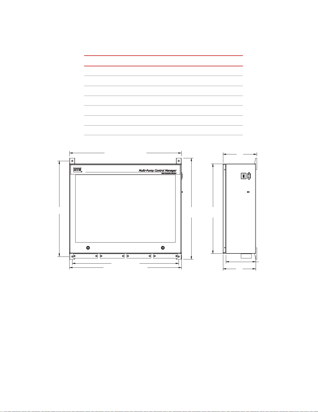
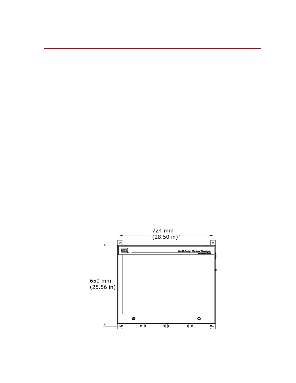
Specifications
25.56
MTG. HOLES
28.50 MTG. HOLES
29.94 MTG. KIT DIMENSION
30.00 ECLOSURE DIMENSION
27.06
MTG. KIT
DIMENSION
DIMENSION
9.04
ENCLOSURE
24.00
8.76
DIMENSION
8.00
ENCLOSURE
Specifications
Parameter Specification
Temperature 5ºC–40ºC (41ºF–104ºF)
Humidity 5–85%, non-condensing
Altitude 2000 m (6,561 ft) maximum
IP rating IP40
Pollution Degree 2
Weight 41 kg (90 lb)
Dimensions See illustration
Multi-Pump Control Manager Introduction
7
Page 8

Specifications
Note Electrical connections must be made by qualified personnel and conform
to local codes and regulations. Local electrical codes supersede any
information found here.
Parameter Specification
100–240 V AC (single phase)
Input Voltage
Input Frequency 50–60 Hz
Input Current
power factor corrected universal
input
4 A at 100 V AC
2 A at 240 V AC
Facility Power Requirements
Input Surge <50 A
Over Voltage Category II
Mark for Canada
Provide a dedicated circuit for the
chassis, computer, and monitor.
This product has been tested to the requirements of CAN/CSA-C22.2 No. 610101, 2nd Edition, including Amendment 1, or a later version of the same standard
incorporating the same level of testing requirements.
8
Introduction
Multi-Pump Control Manager
Page 9

Safety
General Safety Practices
The Multi-Pump Control Manager (MPCM) product family consists of a Basic
Connection Interface (BCI) and typically the optional dedicated PC running the
Supervisor software, with remote E-Stops, Station Flow Managers (SFM), and/or
light stacks as options. Together, these components allow you to remotely run
multiple HPUs similar to operation at the main HPU HMI panel.
The HPU provides high-pressure hydraulic fluid to system components for
system operation. This section provides general information about safety issues
that pertain to system hydraulic supply and distribution components. These
issues include statements to the intended use and foreseeable misuse of the
system and definition for the graphical hazard labeling that is affixed to your
product, and other (more general) safety information that relates to the highpressure and high-performance characteristics of MTS servohydraulic and
electromechanical systems.
General Safety Practices
When you prepare to operate a system that includes hydraulic components,
ensure the following:
• Do not use or allow personnel to operate the system who are not
experienced, trained, or educated in the inherent dangers associated with
high-performance servo hydraulics and who are not experienced, trained, or
educated with regard to the intended operation as it applies to this test
system.
• Do not disable safety components or features (including limit detectors,
light curtains, or proximity switches/detectors).
• Do not attempt to operate the system without appropriate personal safety
gear (for example, hearing, hand, and eye protection).
• Do not modify the system or replace system components using parts that are
not MTS component parts or effect repairs using parts or components that
are not manufactured to MTS specifications.
• Do not use the system in a test area where uncontrolled access to the test
system is allowed when the system is in operation.
• For servohydraulic systems, do not operate the system unless an interlock is
installed to monitor supply pressure into the HSM and initiate a system
interlock if a low or no pressure event occurs.
• Mists of DTE 25 are combustible. Refer to MSDS. You are responsible for
fire prevention measures as per facility or building or other local regulations
and codes
If you have system-related responsibilities (that is, if you are an operator, service
engineer, or maintenance person), you should study safety information carefully
before you attempt to perform any test system procedure.
Multi-Pump Control Manager Safety
9
Page 10

General Safety Practices
You should receive training on this system or a similar system to ensure a
thorough knowledge of your equipment and the safety issues that are associated
with its use. In addition, you should gain an understanding of system functions
by studying the other manuals supplied with your test system. Contact MTS for
information about the content and dates of training classes that are offered.
It is very important that you study the following safety information to ensure that
your facility procedures and the system’s operating environment do not
contribute to or result in a hazardous situation. Remember, you cannot eliminate
all the hazards associated with this system, so you must learn and remain aware
of the hazards that apply to your system at all times. Use these safety guidelines
to help learn and identify hazards so that you can establish appropriate training
and operating procedures and acquire appropriate safety equipment (such as
gloves, goggles, and hearing protection).
Each test system operates within a unique environment which includes the
following known variables:
• Facility variables (facility variables include the structure, atmosphere, and
utilities)
• Unauthorized customer modifications to the equipment
• Operator experience and specialization
• Test specimens
Because of these variables (and the possibility of others), your system can
operate under unforeseen circumstances that can result in an operating
environment with unknown hazards.
Improper installation, operation, or maintenance of your system can result in
hazardous conditions that can cause death, personal injury, or damage to the
equipment or to the specimen. Common sense and a thorough knowledge of the
system’s operating capabilities can help to determine an appropriate and safe
approach to its operation.
Read all manuals Study the contents of this manual and the other manuals provided with your
system before attempting to perform any system function for the first time.
Procedures that seem relatively simple or intuitively obvious may require a
complete understanding of system operation to avoid unsafe or dangerous
situations.
Locate and read
hazard placards/labels
Know facility safe
procedures
Find, read, and follow the hazard placard instructions located on the equipment.
These placards are placed strategically on the equipment to call attention to areas
such as known crush points, electrical voltage, and high pressure hazards.
Most facilities have internal procedures and rules regarding safe practices within
the facility. Be aware of these safe practices and incorporate them into your daily
operation of the system.
10
Know controls Before you operate the system for the first time, make a trial run through the
operating procedures with the power off. Locate all hardware and software
controls and know what their functions are and what adjustments they require. If
any control function or operating adjustment is not clear, review the applicable
information until you understand it thoroughly.
Safety
Multi-Pump Control Manager
Page 11

General Safety Practices
Have first aid available Accidents can happen even when you are careful. Arrange your operator
schedules so that a properly trained person is always close by to render first aid.
In addition, ensure that local emergency contact information is posted clearly and
in sight of the system operator.
Know potential crush
and pinch points
Be aware of
component movement
with hydraulics off
Know electrical
hazards
Be aware of potential crush and pinch points on your system and keep personnel
and equipment clear of these areas.
Remember, when hydraulic power is interrupted on a servohydraulic system, it is
likely that stored accumulator pressure will persist for some time within the
system. In addition, it is likely that as stored energy dissipates, gravity will cause
portions of the system to move.
The actuator rod can also drift down when hydraulics are turned off hitting
anything in its path. This uncommanded movement is because of oil movement
between the pressure/return ports and oil blow by across the piston hub. Be aware
that this can happen and clear the area around the actuator rod when hydraulics
are turned off.
When the system electrical power is turned on, minimize the potential for
electrical shock hazards. Wear clothing and use tools that are properly insulated
for electrical work. Avoid contact with exposed wiring or switch contacts.
Whenever possible, turn off electrical power when you work on or in proximity
to any electrical system component. Observe the same precautions as those given
for any other high-voltage machinery.
Make sure that all electrical components are adequately grounded. Grounds must
remain connected and undisturbed at all times.
Keep bystanders
safely away
Keep bystanders at a safe distance from all equipment. Never allow bystanders to
touch specimens or equipment while the test is running.
Wear proper clothing Do not wear neckties, shop aprons, loose clothing or jewelry, or long hair that
could get caught in equipment and result in an injury. Remove loose clothing or
jewelry and restrain long hair.
Practice good
housekeeping
Protect hoses and
cables
Do not disable safety
devices
Keep the floors in the work area clean. Hydraulic fluid that is spilled on any type
of floor can result in a dangerous, slippery surface. Do not leave tools, fixtures,
or other items not specific to the test, lying about on the floor, system, or decking.
Protect electrical cables from spilled hydraulic fluid and from excessive
temperatures that can cause the cables to harden and eventually fail. Ensure that
all cables have appropriate strain relief devices installed at the cable and near the
connector plug. Do not use the connector plug as a strain relief.
Protect all system hoses and cables from sharp or abrasive objects that can cause
the hose or cable to fail. Never walk on hoses or cables or move heavy objects
over them. Consider hydraulic distribution system layout and route hoses and
cables away from areas that expose them to possible damage.
Your system may have active or passive safety devices installed to prevent
system operation if the device indicates an unsafe condition. Do not disable such
devices as it may result in unexpected system motion.
Multi-Pump Control Manager Safety
11
Page 12

General Safety Practices
Use appropriately
sized fuses
Provide adequate
lighting
Provide means to
access out-of-reach
components
Wear appropriate
personal protection
Handle chemicals
safely
Whenever you replace fuses for the system or supply, ensure that you use a fuse
that is appropriately sized and correctly installed. Undersized or oversized fuses
can result in cables that overheat and fuses that explode. Either instance creates a
fire hazard.
Ensure adequate lighting to minimize the chance of operation errors, equipment
damage, and personal injury. You need to see what you are doing.
Make sure you can access system components that might be out of reach while
standing on the floor. For example, ladders or scaffolding might be required to
reach load cell connectors on tall load units.
Wear eye protection when you work with high-pressure hydraulic fluid,
breakable specimens, or when anything characteristic to the specimen could
break apart.
W ear ear protection when you work near electric motors, pumps, or other devices
that generate high noise levels. Some systems can create sound pressure levels
that exceed 70 dbA during operation.
W ear appropriate personal protection equipment (gloves, boots, suits, respirators)
whenever you work with fluids, chemicals, or powders that can irritate or harm
the skin, respiratory system, or eyes.
Whenever you use or handle chemicals (for example, cleaning fluids, hydraulic
fluid, batteries, contaminated parts, electrical fluids, and maintenance waste),
refer to the appropriate MSDS documentation for that material and determine the
appropriate measures and equipment required to handle and use the chemical
safely. Ensure that the chemical is disposed of appropriately.
Know system
interlocks
Interlock devices should always be used and properly adjusted. Interlock devices
are designed to minimize the chance of accidental damage to the test specimen or
the equipment. Test all interlock devices for proper operation immediately before
a test. Do not disable or bypass any interlock devices as doing so could allow
hydraulic pressure to be applied regardless of the true interlock condition. The
Reset/Override button is a software function that can be used to temporarily
override an interlock while attempting to gain control of the system.
Ensure secure cables Do not change any cable connections when electrical power or hydraulic pressure
is applied. If you attempt to change a cable connection while the system is in
operation, an open control loop condition can result. An open control loop
condition can cause a rapid, unexpected system response which can result in
severe personal injury, death, or damage to equipment. Also, ensure that all
cables are connected after you make any changes in the system configuration.
Stay alert A void long periods of work without adequate rest. In addition, avoid long periods
of repetitious, unvarying, or monotonous work because these conditions can
contribute to accidents and hazardous situations. If you are too familiar with the
work environment, it is easy to overlook potential hazards that exist in that
environment.
12
Safety
Multi-Pump Control Manager
Page 13

General Safety Practices
Know the causes of
unexpected actuator
motions
Do not use RF
transmitters
The high force and velocity capabilities of MTS actuators can be destructive and
dangerous (especially if actuator motion is unexpected). The most likely causes
of unexpected actuator response are operator error and equipment failure due to
damage or abuse (such as broken, cut, or crushed cables and hoses; shorted wires;
overstressed feedback devices; and damaged components within the servocontrol
loop). Eliminate any condition that could cause unexpected actuator motion.
Keep radio frequency (RF) transmitters away from the workstation computers,
remote terminals, and electronics consoles. Intense RF fields can cause erratic
operation of the more sensitive circuits in the system.
Multi-Pump Control Manager Safety
13
Page 14

General Safety Practices
14
Safety
Multi-Pump Control Manager
Page 15
Installation
The Multi-Pump Control Manager (MPCM) allows you to operate up to eight
Hydraulic Power Units (HPUs) remotely. Standard installation involves
placement of the components and cabling connections.
Placement of Components
Because all connections between components run through the Basic Connection
Interface (BCI), it is usually placed in a central location; typically next to the
HPUs.
The dedicated PC running the Supervisor software is usually placed in the
control room.
Station Flow Managers (SFMs) are usually placed in alternate control rooms or
next to the test rig.
Remote E-Stops are usually placed at strategic locations, such as near exits from
the test rig.
Placement of Components
Mount the BCI
Light stacks are strategically placed to be able to observe alarm and fault status in
case problems arise that require attention.
Four mounting brackets are provided on the BCI: two top and two bottom. Mount
the BCI using hardware that can support 50 kg (110 lbs); including the weight of
the BCI and attached cables.
Multi-Pump Control Manager Installation
15
Page 16

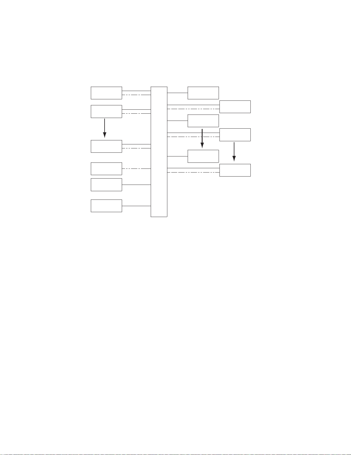
Spacing Requirements
HPU #2
HPU #1
E-STOP #1
E-STOP #2
E-STOP #8
SFM #1
SFM #7
SFM #8
OR
OR
OR
SUPERVISOR PC
LIGHT STACK(S)
SUPERVISOR
E-STOP
HPU #8
BCI
(DAISY CHAIN MULTIPLE LIGHT BARS,2 AMPS
PER CHANNEL NOT TO EXCEED 6 AMPS TOTAL)
Spacing Requirements
Cabling
The front of the enclosure requires 65 cm (25.6 in) minimum of clearance so the
door can be opened by MTS service personnel. The power entry side of the
enclosure requires 16 cm (6.3 in) minimum of clearance for the power cord. The
bottom of the enclosure requires 65 cm (25.6 in) minimum of clearance for the
cables.
The dimensions above are minimum dimensions for the BCI. MTS recommends
an additional 1m (40 in) of clearance around the BCI to ease installation and
should service be necessary.
Cabling consists of connecting the cables from all the associated components to
the BCI. Shown below is a block diagram of connections.
A detailed field wiring diagram (MTS Drawing number 700-005-779) can be
found on the Product Information CD.
Lifting Instructions
AC Power Disconnect Requirements
External Device Connections
16
Installation
The MPCM weighs about 41 kg (90 lb). Improper lifting techniques can cause
strained muscles and back injuries. When lifting the MPCM, take the appropriate
precautions to prevent injuries to yourself.
Be sure to locate the MPCM so that you have adequate access to disconnect the
power cord from the unit.
The MPCM is designed to work with MTS supplied devices. Only MTS supplied
devices should be connected to the MPCM.
Multi-Pump Control Manager
Page 17

Operation
WARNING
Set HPU to Remote Operation for use with the MPCM
This section deals with operation of the Multi-Pump Control Manager (MPCM)
only. It is assumed that the hydraulic power unit (HPU) has been properly set up
and you are familiar with all operating aspects of the HPU.
Remote operation of up to eight HPUs can be done from the MPCM. Most
operation is the same as operation of the HPU from the Human Machine
Interface (HMI) panel on the HPU main electrical enclosure.
The MPCM provides all the same operation features as the main operator’s panel
on the HPU excluding setup and those dealing with safety.
Due to the various modes of operation, components connected to the
MPCM BCI can start without prior notice.
Components include but are not limited to: HPUs, Motor Modules, or
Cooling Supply Circuits.
Lockout tagout procedures should be followed when maintenance is performed on
any component connected to the MPCM BCI.
Set HPU to Remote Operation for use with the MPCM Supervisor
T o control the HPUs from the MPCM, the HPU(s) must be in Remote mode. The
following procedure is from the HPU manual and provided here for reference.
Note Perform the following steps on each HPU in the system.
1. Make a general inspection of the HPU. Ensure that all cooling water valves
are open. Ensure the Emergency Stop button is released.
2. If not already displayed, press the Setup button to display the Setup screen.
Once on the Setup page press the Setup button again to display the Service
screen. Once on the Service screen press the PLC Network button to
display the PLC Network screen.
3. Verify that the Control Source button displays Ethernet. If the button
displays DIO press the button to toggle the HPU into Ethernet source
control.
4. Verify that HPU address is appropriately numbered.
5. Press the Back button to return to the Service screen. Once on the Service
screen press the Back button again to return to the Setup screen. Once on
the Setup screen, press the Main button to display the Main screen.
6. Verify that the Remote Operation button is green. If the button is not green,
press the button to change it to green (indicating remote mode).
Multi-Pump Control Manager Operation
17
Page 18

Setup
Setup
Note Perform the following steps on the MPCM Supervisor.
7. If not already displayed, press the Unit button to display the Unit screen.
8. Verify that each HPU in the system is in Remote Ethernet mode and does
not have a Comm alarm.
Note Each HPU in the system will have to be configured on the Supervisor
Setup Screen. See Setup section for more information.
1. From Supervisor HMI, enter MPCM Supervisor software if not already
displayed.
2. Select desired language and press Main Display.
3. From the Main screen press Setup to go to the Supervisor Setup screen
4. For each HPU Platform in the system, select the model of the HPU.
A. Press down on the type of HPU, and toggle up or down using the up or
down arrows until the correct model is displayed.
B. Press OK to select model.
5. Set System Transducers by pressing each associated button to toggle
between Sensor Present and Sensor Not Present
6. Set System Units by pressing each associated button to toggle between
Metric and English Units.
7. Set System Design Pressure by pressing on associated value button and
toggling up or down using the up or down arrows until the correct System
Design Pressure is displayed. Press OK to select System Design Pressure.
8. If flow meters are present on each HPU and the associated System
Transducer button for HPU Flow Sensors has been toggled to Present, ROD
settings will appear. Adjust each setting following the steps below.
A. Press the associated value button to display the keypad.
B. With the keypad displayed, use the number keys to set the desired flow
level.
C. Press Enter to set the value and return to the Setup screen.
9. Press the Status button to display the Status screen.
A. Enter a name in the chain for each External E-Stop chain present that
has indicate compatibility.
18
Operation
B. To display the keypad, press the pushbutton for the associated chain.
C. Enter in the name for the external e-stop chain.
D. Press Enter to accept the name and return to the Status screen
Multi-Pump Control Manager
Page 19

Startup and Main Screen
Note The following screen images may be from the 4 or 8 HPU version of the
The Startup screen is displayed initially when the MPCM is powered up.
Startup and Main Screen
HMI software. Your actual display may vary slightly. Features that only
exist in the 8 HPU version of the software will be listed as such.
The Main screen is displayed after you select the language. The push button/
indicators on the right are used to select the various screens.
Multi-Pump Control Manager Operation
19
Page 20

System
System
The System screen provides an overview of the status of the entire hydraulic
system. The RUN and PRESSURE buttons control application of hydraulic
pressure to the system (not individual units). The following table describes the
controls and indicators of the System panel.
20
Operation
Multi-Pump Control Manager
Page 21

Item Name Description
System
1 System gauges: Flow/Pressure/
T emperature
2 HPU gauges: Flow (optional)
System gauges. The parameters of these gauges are
determined by settings on the MPCM Setup screen.
Flow - LPM or GPM. Gauge full scale is determined by
the total number of modules present. Green range is
determined by the total number of modules running in the
system. Gauge reading is the current flow if a flow meter
is present on all HPU(s). If a flow meter is not present,
the gauge reading is the flow demand in the Auto mode.
If flow meters are not present and the system is being
operated in manual mode, gauge will read zero.
Pressure (optional)- MPa or PSI. Full scale reading is
determined by values set on the Setup screen. Gauge is
not shown if sensor is not present and enabled.
Temperature (optional)- °C or °F. Full scale reading is
determined by values set on the Setup screen. Gauge is
not shown if sensor is not present and enabled.
Red/green/yellow ranges are normalized based on system
setup.
Flow - LPM or GPM. Gauge full scale is determined by
the number of modules present on that HPU. Green
gauge range is determined by the number of modules
running on that HPU.
3 HPU gauges: Pressure/
T emperature/Level
Gauge is configured in the Setup page on the HPU.
Gauge is not shown if flow meter is not present and
enabled.
Pressure - MPa or PSI. Gauge reading is determined by
HPU’s sensor.
Temperature - °C or °F. Gauge reading is determined by
HPU’s sensor.
Red/green/yellow ranges are normalized based on HPU
setup.
Level - status bar. Colored area indicates fluid level
relative to full capacity (in eights) which is represented
by the overall bar:
flashing red - 0/8
yellow - 1/8
green - 2/8 to 7/8
flashing red - 8/8
Multi-Pump Control Manager Operation
21
Page 22

System
Item Name Description
4 Module indicators
5 Run/Pressure switch
6, 7 System background
HPU background
Color scheme for the module icons is:
• Dashed outline - not present
• Gray with black border - present but not enabled
• Gray with green border - present and enabled
• Green flashing - running in low pressure
• Green solid - running in high pressure
• Red - module fault: sequence or overload
Run O/I: The O (red) switch stops all HPUs. The I
(green) switch starts all enabled HPU modules in low
pressure. In Auto, Run starts present modules with
lowest hours to meet flow demand.
Pressure I/II: The I (yellow) switch will cause all HPU
modules running in high pressure to return to low
pressure. The II (green) switch changes all HPU modules
running in low pressure to high pressure.
Gray - no faults or alarms
Red - fault
Yellow - alarm
8Auto
9 ROD (Run On Demand)
(optional)
Note that all HPU alarms will cause a system alarm, but
not all HPU faults will cause a system fault. Refer to the
HPU manual for additional information.
Push button/Indicator. Change between manual mode and
auto mode. Auto mode will start the modules with the
lowest hours first until the demand is satisfied.
Auto - gray: Indicates the system is in manual mode.
Auto- green: Indicates the system is in auto mode.
When using the auto mode, you need to set the flow
demand. Push the associated value pushbutton below the
Flow Demand title to display the keypad. With the
keypad displayed, use the number keys to set the desired
flow level and then press Enter to set the value and return
to the Main screen.
Pushbutton/Indicator. Used to automatically control
pump operation as system demand changes. The ROD
button is only shown when in auto mode.
ROD - gray: Indicates Run On Demand is not enabled.
ROD- green: Indicates Run On Demand is enabled.
22
Operation
Multi-Pump Control Manager
Page 23

Unit
Unit
The Unit screen displays the HPU operational status. All available HPUs will be
displayed in individual panes. Shown below is an example. The following table
describes the controls and indicators of the Unit panes.
Multi-Pump Control Manager Operation
23
Page 24

Unit
Item Name Description
1 Faulted/Ready/Running/High
Pressure/Alarm/Overtemp Bypass
2 Module #n Enabled
Indicator. Indicates the various states of the HPU.
Faulted - red: Indicates when an interlock has occurred and
the HPU has been shut down. Possible faults include E-Stop,
watchdog timer, low level and high temperature.
Ready - green: Indicates the interlocks are cleared and the
HPU is ready to start.
Running - green: Indicates the HPU is running in low
pressure.
High Pressure - green: Indicates at least one pump motor is
running in high pressure.
Alarm - yellow: Indicates a filter is dirty and needs attention
or hydraulic fluid temperature alarm (user set) has been
activated. A module fault will also activate an alarm.
Overtemp Bypass - yellow: Indicates an overtemperature
interlock has occurred and the HPU has been put into a
bypass mode to circulate hydraulic fluid through the heat
exchanger.
Enable Module - blue: Indicates that no modules are enabled.
It alerts you to enable one or more modules before the HPU
can be started.
Pushbutton/Indicator. Used to enable and disable the
available pump modules. Pressing the button alternates
between the two states.
Enable Module #N - gray: Indicates the pump module is
disabled and cannot be started.
Module #N Enabled - green frame: Indicates the pump
module is enabled and can be started.
Module #N Enabled - flashing green button: Indicates the
pump module is running in low pressure.
Module #N Enabled - solid green: Indicates the pump module
is running in high pressure.
Fault - red: lights when the module has an overload or a
contactor sequence fault.
24
Operation
Multi-Pump Control Manager
Page 25

Item Name Description
Unit
3 Run/Stop/Bypass
4 High Pressure
Pushbutton/Indicator. Pushbutton used to start and stop the
HPU.
Run - gray. black letters: In this state, press to start the HPU.
Stop - gray, red lett ers: In this state, press to stop the HPU.
Bypass - blue, white letters: In this state, press to start the
HPU in bypass mode. The Faulted state will turn to
Overtemp Bypass. Bypass mode only occurs during an
overtemperature condition and allows the HPU to run in low
pressure to cool the hydraulic fluid. An internal timer allow
the bypass mode to run for five minutes. It might be
necessary to repeat activating the bypasss mode several times
before fluid temperature is within an acceptable range,
In remote operation, the run and bypass buttons are disabled.
Pushbutton/Indicator. Used to put the HPU in high pressure
or return to running; pushbutton acts as a toggle between the
two modes.
High Pressure - gray: indicates the HPU is not in high
pressure.
High Pressure - green: Directs the HPU to sequence to high
pressure. When the HPU is in high pressure it will be
indicated on the main display.
5 Local/Remote DIO/Remote ENET
6Auto
7 ROD (Run On Demand)
(optional)
In remote operation, the High Pressure button is disabled.
Indicators. Used to indicate which method is being used to
control the HPU.
Note The unit must be in Remote ENET to operate with
the MPCM. This can only be changed at the HPU.
Pushbutton/Indicator. Change between manual mode and
auto mode. Auto mode will start the modules with the lowest
hours first until the demand is satisfied.
Auto - gray: Indicates the HPU is in manual mode.
Auto- green: Indicates the HPU is in auto mode.
When using the auto mode, you need to set the flow demand.
Push the associated value pushbutton below the Flow
Demand title to display the keypad. With the keypad
displayed, use the number keys to set the desired flow level
and then press Enter to set the value and return to the Main
screen.
Pushbutton/Indicator. Used to automatically control pump
operation as system demand changes. The ROD button is
only shown when in auto mode.
ROD - gray: Indicates Run On Demand is not enabled.
ROD- green: Indicates Run On Demand is enabled.
Multi-Pump Control Manager Operation
25
Page 26

Unit
Item Name Description
8Unit Hours
9 Oil Pressure
10 Oil Temperature
11 Oil Level
12 Oil Flow (optional)
Indicator/Display: Indicates total running time of the HPU.
Indicator/Display: Indicates output pressure of the HPU.
Indicator/Display: Indicates the temperature of the hydraulic
fluid in the reservoir.
Indicator/Display: Displays the level of the hydraulic fluid in
the reservoir in 1/8 increments. The level is relative to the
usable oil volume. Note that the oil level switch, which
controls the low level interlock, can be set at a level higher
than the oil level sensor. Values will match when the oil level
switch is set at its lowest setting.
Indicator/Display: Displays the total hydraulic fluid flow
from all running pumps. Requires that the flow meter and
ROD are present and enabled.
26
Operation
Multi-Pump Control Manager
Page 27

Status Screen
Status Screen
The Status screen is displayed by pressing the Status button on the Main screen.
The following table describes the pushbuttons and indicators on the Status
screen.
Item Name Description
1E- Stop
2Watchdog
Indicator. Used to indicate whether the HPU’s safety relay is
tripped.
E-Stop - gray - OK: Indicates the HPU’s safety relay has not
tripped.
E-Stop - red - Fault: Indicates the HPU’s safety relay has tripped.
The cause of a safety relay trip is either an external E-stop Button
or the HPU watchdog timer (if the watchdog timer is also red).
E-Stop Button - red - Fault: Indicates the HPU’s safety relay has
tripped. The cause of a safety relay trip is the E-Stop Button on the
HPU.
Indicator. Used to indicate the status of the watchdog timer.
W atchdog - gray - OK: Indicates the PLC that controls the HPU is
operating normally.
Watchdog - red - fault: Indicates there is a problem with the
hardware watchdog timer and the PLC is not operating correctly.
A watchdog fault cause the HPU to shut down.
Multi-Pump Control Manager Operation
27
Page 28

Status Screen
Item Name Description
3 Oil Level
4 Oil Temp
5 Return Filter
Indicator. Used to indicate if the hydraulic fluid level is within
acceptable limits.
Oil Level - gray - OK: Indicates the hydraulic fluid level is within
acceptable limits.
Oil Level Fault - red: Indicates the hydraulic fluid level is not
within acceptable limits and an interlock is active.
Indicator. Used to indicate if the hydraulic fluid temperature is
within acceptable limits.
Oil Temp - gray - OK: Indicates the hydraulic fluid temperature is
within acceptable limits.
Oil Temp - yellow - alarm: Indicates that the hydraulic fluid
temperature has exceeded the user-configured alarm value.
Oil Temp - red - Fault: Indicates the hydraulic fluid temperature is
not within acceptable limits and an interlock is active.
Indicator. Used to indicate if the return filter is within acceptable
limits.
Return Filter - gray - OK: Indicates the contamination in the return
filter is within acceptable limits.
Return Filter - yellow - alert: Indicates the contamination in the
return filter is not within acceptable limits. This state will not
generate an active interlock, but alerts you that the filter requires
maintenance.
6 Pressure Filter (optional)
7 Module #N
The HPU cannot be started with an active return filter alert.
Indicator. Used to indicate if the pressure filter is within
acceptable limits.
Press Filter - gray - OK: Indicates the contamination in the
pressure filter is within acceptable limits.
Press Filter - yellow - alert: Indicates the contamination in the
pressure filter is not within acceptable limits. This state will not
generate an active interlock, but alerts you that the filter requires
maintenance.
The HPU cannot be started with an active pressure filter alert.
Indicator. Used as an identifier for the Status and Hours
parameters.
Module - gray: Label.
#N - gray: #1 is associated with pump module 1. #2 is associated
with pump module 2, and so forth.
28
Operation
Multi-Pump Control Manager
Page 29

Item Name Description
Status Screen
8Status
9Hours
Indicator: Indicates the state of the associated module.
Status - gray: Label.
Not Present - light gray: Indicates the module is not present.
Ready- green: Indicates the module is present but is not enabled.
Enabled - green: Indicates the module is enabled and is ready to
into a run condition (replaces READY).
Running Low- green: Indicates the associated pump module is
running in low pressure.
High Pressure - green: Indicates the associated pump module is
running in high pressure.
Overload - red: Indicates an overload condition exists and a fault
is active for the associated module
Sequence - red: Indicates that the PLC commanded the motor
contactor to close, but the contactor did not close after a 10 second
time period and a fault is active.
Indicator: Indicates the running time in hours of the associated
module.
Hours - gray: Label.
Value - gray: The number of total hours the associated module has
been running.
10 Mute
11 Stop Relay Indicator
12 HMI E-Stop Indicator
13 External E-Stops
Pushbutton Indicator
Pushbutton: Allow you to mute the light buzzer if a fault or alarm
activates.
Indicates whether the MPCM's safety relay is tripped.
E-Stop Relay - gray - OK: indicates the MPCM's safety relay has
not tripped.
E-Stop Relay - red - Fault: Indicates that the MPCM's safety relay
has tripped.
The cause of a safety relay trip is either an External E-Stop
Button, an HPU E-Stop Button, or an HPU Watchdog tim er.
Indicates whether the HMI E-Stop Button has been pressed.
HMI E-Stop - gray - OK: Indicates that the HMI E-Stop button has
not been pressed and is in the reset (closed) state.
HMI E-Stop - red - Fault: Indicates that the HMI E-Stop Button
has been pressed and is in the open state.
Indicates whether an external E-Stop chain has been pressed. User
defined text.
Text - gray - OK: Specific external e-stop chain does not have a
button that has been pressed and is in the reset (closed state).
Text - red - Fault: Indicates that the specific external e-stop chain
has an e-stop button that has been pressed, and is in the open state.
Multi-Pump Control Manager Operation
29
Page 30

Status Screen
Item Name Description
14 Flow Demand Indicator
15 PLC Comm Indicator
16 HPU # Comm Indicator
Indicates whether the user(s) are demanding a total flow demand
that is within the maximum capacity of the system.
Flow Demand - gray - OK: Indicates that the Total Flow Demand
is within the maximum capacity of the system.
Flow Demand - yellow - Alarm: Indicates that the Total Flow
Demand is above the maximum flow capacity of the system.
Indicates whether the Supervisor PC is able to communicate with
the PLC.
PLC Comm - gray - OK: Supervisor PC is communicating with
the PLC.
PLC Comm - Alarm: Indicates that the Supervisor PC has lost
communication with the PLC.
The PLC will continue to operate in the last commanded state
until communication is regained.
Indicates whether the PLC is able to communicate with the HPU.
HPU # Comm - gray - OK: PLC is communicating with the HPU.
HPU # Comm - Alarm: Indicated that the PLC has lost
communication with the HPU.
The HPU will continue to operate in the last commanded state
until communication is regained.
17 Status 1-4 Pushbutton
(8 HPU version only)
18 Status 5-8 Pushbutton
(8 HPU version only)
Displays the status of Units 1-4
Status 1-4 - black - Status of units 1-4 are being displayed.
Status 1-4 - gray - Status of units 5-8 are being displayed.
Displays the status of Units 5-8
Status 5-8 - black - Status of units 5-8 are being displayed.
Status 5-8 - gray - Status of units 1-4 are being displayed.
30
Operation
Multi-Pump Control Manager
Page 31

Setup
Setup
On the Supervisor HMI, press the Setup button to display the System Setup
screen.
The following table describes the pushbuttons and indicators on the Setup
screen.
Item Name Description
1 HPU Platform
2 System Transducers
3 System Units
4 System Design Pressure
Indicator. Displays the MTS model number of the HPU.
Indicators. Used to indicate the presence of various sensors.
Sensor not present - gray.
Sensor present - black.
Pushbutton/Indicator: Used to select the units for display. Push to
alternate between Metric and English units.
Pressure Display in PSI,
Pressure Display in MPa,
Indicator. Displays the system hydraulic pressure:
21 MPa (3000 psi), 27.5 MPa (4000 psi), or 34.0 MPa (5000 psi).
°F, GPM- gray.
°C, LPM - black.
Multi-Pump Control Manager Operation
31
Page 32

Stat ion
Item Name Description
5 Serial Number, HMI Software
Part Number, PLC Sof tware Part
Number
6 System ROD Setup
(flow sensor must be present
and enabled)
Station
The Station Flow Manager screen allows you to control the flow demand inputs.
Information fields.
These pushbutton/indicators [Minimum Flow, Flow Buffer, On
Delay (sec), and Off Delay (sec)] allow you to set up the Run On
Demand parameters. Refer to “Setting Up System Run On
Demand (ROD)” on page 35 and “Run On Demand Detailed
Example” on page 36 for a detailed description.
32
Operation
Item Description
1
Display. Clicking this field shows an alpha-numeric keypad that
lets you enter a name for the station.
2
Pushbutton/Indicator. Used to turn on/off the associated channel.
Gray = off. Green = on. Green with hash marks = the channel is
controlled by DIO. These only function with the system in the
Auto mode.
Multi-Pump Control Manager
Page 33

Item Description
Operating the HPU Locally or Remotely
3
Clicking this field brings up a numeric keypad that lets you enter
the flow demand requirement for the associated channel.
4
Total Flow Demand indicator. This displays the total demand as
defined by the Flow Demand entries (item 3) plus the flow
demand available from the System screen, This indicator turns
yellow if the flow demand exceeds total capacity . Refer to “Auto,”
on page 22.
Operating the HPU Locally or Remotely
The HPU can be operated locally using the controls on the user interface panel or
remotely using your Supervisor HMI.
Note The BCI safety relay needs to be in the "go" state or not tripped. If the
BCI does not have power and the HPU is connected to the BCI then the
HPU cannot be run locally.
Local operation 1. Make a general inspection of the HPU. Ensure that all cooling water valves
are open. Ensure the Emergency Stop button is released.
2. If not already displayed, press the Status button to display the Status screen.
3. Verify that Unit does not have any faults or alarms. If a fault or alarm exists
press the Reset button to attempt to reset. If unit does not reset consult HPU
manual for further information.
If not already displayed, press the Main button to display the Main screen.
4. Verify that the Remote Operation button is gray. If the button is green,
press the button to change it to gray (indicating local mode).
5. Verify that at least one pump is enabled. Enable additio nal pumps as
necessary.
6. Press Run to start the pumps. The pumps start sequentially to reduce inrush
current amplitude. Each pump starts in low pressure mode.
7. Check the HPU for leaks and unusual sounds. Stop the HPU immediately if
leaks or unusual sounds are noted. Determine the cause and fix the problem
before restarting the HPU.
8. Press High Pressure to turn on high hy draulic pressure.
Note If the HPU generates an interlock during operation (such as low fluid
level or high temperature), the HPU will stop. Once the cause has been
corrected, press the Reset button before restarting.
9. Run the HPU for about 30 minutes or until the hydraulic fluid is up to
operating temperature [typically
43°C to 49°C (110°F to 120°F)] before
using your test system.
10. When in high pressure mode, press the High Pressure button to return to
low pressure mode.
11. To stop the HPU, press the Stop button.
Multi-Pump Control Manager Operation
33
Page 34

How to Clean the MPCM
Remote operation Note Perform the following steps on the MPCM Supervisor.
1. Configure each HPU according to the “Set HPU to Remote Operation for
use with the MPCM Supervisor” section.
2. If not already displayed, press the Status button to display the Status screen.
3. Verify that each Unit and System does not have any faults or alarms. If a
fault or alarm exists press the Reset button to attempt to reset the fault or
alarm. If unit does not reset consult HPU manual for further information.
4. Press the Unit button to display the Unit screen
5. Verify that the Remote Operation button is green on each HPU that is to be
run. If the button is not green on a specific HPU, revisit "Set HPU to
Remote Operation for use with the MPCM Supervisor" section to insure that
the HPU has been put into remote mode.
6. Verify that at least one pump is enabled. Enable additio nal pumps as
necessary.
7. Start each HPU in low pressure by pressing Run for each HPU that is to be
run.
How to Clean the MPCM
8. Check the HPU for leaks and unusual sounds. Stop the HPU immediately if
leaks or unusual sounds are noted. Determine the cause and fix the problem
before restarting the HPU.
9. Select High Pressure for each HPU that is to be at High Pressure.
Note There are other methods for running the system. Refer to the System
and Unit screen information, or the videos supplied on the CD.
Remove dust and dirt from the chassis with an appropriate cleaner for
electronics.
34
Operation
Multi-Pump Control Manager
Page 35

Appendix
Contents Setting Up System Run On Demand (ROD) 35
Run On Demand Detailed Example 36
Setting Up System Run On Demand (ROD)
The ROD option automatically starts or stops pumps to meet the hydraulic flow
demand from the system. The PLC monitors the hydraulic fluid flow. When the
flow changes beyond a trigger point for a set period of time, one or more of the
pumps are turned on or off.
Note Flow meters must be present on all HPU(s) within the system for ROD to
operate properly.
Refer to the previous table for a description of the controls referenced in the
following procedure.
1. On each HPU in the system, from the current screen, press the AUTO Setup
button. When the Auto Setup screen displays, make sure the Flow Meter
indicator is in the Flow Meter Present state (blue-green).
Setting Up System Run On Demand (ROD)
2. On each HPU in the system, check the Rated Flow Per Module.
If necessary , press the associated value pushbutton to change the flow value.
This value should only require change if the HPU is provided with pump
modules that have a different full flow rating. Refer to the HPU manual for
further information.
3. On the Supervisor HMI, from the current screen, press the Main button and
then the Setup button. When the Setup screen displays. make sure the Flow
Meter indicator is in the HPU Flow Sensors Present state (black).
4. Set the Minimum Flow.
If necessary, press the associated value pushbutton to display the numeric
keypad and change the value. Press Enter to set the value and return to the
Auto Setup screen. The range shown on the numeric keypad depends on the
number of pump modules present.
5. Set the Flow Buffer.
If necessary, press the associated value pushbutton to display the numeric
keypad and change the value. Press Enter to set the value and return to the
Auto Setup screen. The range shown on the numeric keypad depends on the
number of pump modules present.
6. Check the On Delay.
If necessary, press the associated value pushbutton to change the delay time.
Use the numeric keypad described above to increase or decrease the delay.
Multi-Pump Control Manager Appendix
35
Page 36

Run On Demand Detailed Example
7. Check the Off Delay.
If necessary, press the associated value pushbutton to change the delay time.
Use the numeric keypad described above to increase or decrease the delay.
8. Press the System button to return to the System screen.
9. Press the Auto button to enable Auto. The button will turn green.
10. Press the ROD button to enable the run on demand option. The button will
turn green.
11. Press I (green) to start the HPU in low pressure.
12. Press II (green) to select high pressure mode.
The number of pumps running will be determined by the setting on the
Setup screen.
13. Pressing the O (red) button will turn off the HPU(s) that are running.
Run On Demand Detailed Example
Run On Demand (ROD) is a system that monitors the output flow of the
Hydraulic Power Units (HPUs) and turns on and off pumping modules as needed
to best meet the users demands. The parameters for ROD that need to be set by
the user include:
• On Delay: the period of time that must pass where the criteria are met or
exceeded before the next module(s) will be turned on.
• Off Delay: the period of time that must pass where the criteria are met or
exceeded before the next module(s) will be turned off.
• Module Flow: the flow capability of a single pumping module within the
HPU (see table). This must be confirmed at each HPU.
• Minimum Flow: the minimum flow capacity that should be available when
the system is on.
• Flow Buffer: the minimum flow that should be available beyond the actual
current flow. Flow is added for each HPU to compensate for the circulation
pump within each running HPU.
For reference in setting up run on demand, the fo l lo w ing table shows the flow
capacity of the available pump modules.
Pressure
Frequency
21 MPa
3000 psi
50 Hz 100 lpm
27.5 MPa
4000 psi
75 lpm
34.4 MPa
5000 psi
50 lpm
36
Appendix
26 gpm
20 gpm
13 gpm
Multi-Pump Control Manager
Page 37

Run On Demand Detailed Example
60 Hz 113 lpm
30 gpm
85 lpm
22 gpm
61 lpm
16 gpm
An example is shown below. In the example Module Flow is set at 30 gpm,
Minimum Flow is set at 10 gpm, Flow Buffer is set at 4 gpm (which means the
total actual buffer is 10 gpm), Δt
represents the on delay, and Δt
on
represents
off
off delay. The system starts out with one module running to create 30 gpm of
available flow. This satisfies both the Minimum Flow requirement (10 gpm) and
the Flow Buffer requirement (10 gpm). The demand rises and eventually hits 20
gpm. At this point the on delay is started because the 20 gpm of actual flow and
10 gpm of Flow Buffer meet or exceed the available 30 gpm. Because the flow
stays above 20 gpm for the length of time Δt
, another pump module is started
on
and available flow goes to 60 gpm. Then a spike occurs which exceeds the
available flow but because the duration of the spike is less than Δt
, another
on
pump module is not started. Flow then continues to increase but never exceeding
the next trigger point of 50 gpm for a duration of Δt
. Then flow drops off below
on
20 gpm. Because the flow does not stay below 20 gpm for the period of time
, no pump modules are turned off. Finally the flow tapers off and flow is
Δt
off
below 20 gpm for the time Δt
and the second pump module is turned off.
off
Flow buer
Flow buer
Multi-Pump Control Manager Appendix
37
Page 38

Run On Demand Detailed Example
38
Appendix
Multi-Pump Control Manager
Page 39

Page 40

m
MTS Systems Corporation
14000 Technology Drive
Eden Prairie, Minnesota 55344-2290 USA
Toll Free Phone: 800-328-2255
(within the U.S. or Canada)
Phone: 952-937-4000
(outside the U.S. or Canada)
Fax: 952-937-4515
E-mail: info@mts.com
http://www.mts.com
ISO 9001 Certified QMS
 Loading...