


 Loading...
Unpacking
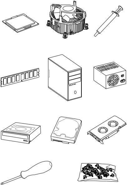
Thank you for buying the MSI® X299 TOMAHAWK/ X299 TOMAHAWK AC motherboard. Check to make sure your motherboard box contains the following items. If something is missing, contact your dealer as soon as possible.
|
|
|
|
|
|
|
|
|
|
|
|
|
|
|
|
|
|
|
|
|
|
|
|
|
|
|
|
|
|
|
|
|
|
|
|
|
|
|
|
|
|
|
|
|
|
|
|
|
|
|
|
|
|
|
|
|
|
|
|
|
|
|
|
|
|
|
|
|
|
|
|
|
|
|
|
|
|
|
|
|
|
|
|
|
|
|
|
|
|
|
|
|
|
|
|
|
|
|
|
|
|
|
|
|
|
|
|
|
|
|
|
|
|
|
|
|
|
|
|
|
|
|
|
|
|
|
|
|
|
|
|
|
|
|
|
|
|
|
|
|
|
|
|
|
|
|
|
|
|
|
|
|
|
|
|
|
|
|
|
|
|
|
|
|
|
|
|
|
|
|
|
|
|
|
|
|
|
|
|
|
|
|
|
|
|
|
|
|
|
|
|
|
|
|
|
|
|
|
|
|
|
|
|
|
|
|
|
|
|
|
|
|
|
|
|
|
|
|
|
|
|
|
|
|
|
|
|
|
|
|
|
|
|
|
|
|
|
|
|
|
|
|
|
|
|
|
|
|
|
|
|
|
|
|
|
|
|
|
|
|
|
|
|
|
|
|
|
|
|
|
|
|
|
|
|
|
|
|
|
|
|
|
|
|
|
|
|
|
|
|
|
|
|
|
|
|
|
|
|
|
|
|
|
|
|
|
|
|
|
|
|
|
|
|
|
|
|
|
|
|
|
|
|
|
|
|
|
|
|
|
|
|
|
|
|
|
|
|
|
|
|
|
|
|
|
|
|
|
|
|
|
|
|
|
|
|
|
|
|
|
|
|
|
|
|
|
|
|
|
|
|
|
|
|
|
|
|
|
|
|
|
|
|
|
|
|
|
|
|
|
|
|
|
|
|
|
|
|
|
|
|
|
|
|
|
|
|
|
|
|
|
|
|
|
|
|
|
|
|
|
|
Drivers & Utilities |
Motherboard User |
|
|
|
|
|
|
|
|
|
|
|
|
|
|
|
|
|
|
|
|
|
|
|
|||
|
|
|
|
|
|
|
|
|
|
|
|
|
|
|
|
|
|
|
|
|
|
|||
|
|
|
|
|
|
|
|
|
|
|
|
|
|
|
|
|
|
|
|
|
|
Disc |
||
|
|
|
|
|
|
|
|
|
|
|
|
|
|
|
|
|
|
|
|
|
|
|||
|
|
|
|
|
|
|
|
|
|
|
|
|
|
|
|
|
|
|
|
|
|
|
|
Guide |
|
|
|
|
|
|
|
|
|
|
|
|
|
|
|
|
|
|
|
|
|
|
|
|
|
Motherboard
I/O Shield
SLI HB Bridge M x1
SATA Cable x2
SATA Cable Labels |
Case Badge |
Antenna x2 |
|
|
(Optional) |
*These pictures are for reference only and may vary without notice.
**The packing contents may vary according to the country you purchased.
Unpacking 1
Safety Information
yThe components included in this package are prone to damage from electrostatic discharge (ESD). Please adhere to the following instructions to ensure successful computer assembly.
yEnsure that all components are securely connected. Loose connections may cause the computer to not recognize a component or fail to start.
yHold the motherboard by the edges to avoid touching sensitive components.
yIt is recommended to wear an electrostatic discharge (ESD) wrist strap when handling the motherboard to prevent electrostatic damage. If an ESD wrist strap is not available, discharge yourself of static electricity by touching another metal object before handling the motherboard.
yStore the motherboard in an electrostatic shielding container or on an anti-static pad whenever the motherboard is not installed.
yBefore turning on the computer, ensure that there are no loose screws or metal components on the motherboard or anywhere within the computer case.
yDo not boot the computer before installation is completed. This could cause permanent damage to the components as well as injury to the user.
yIf you need help during any installation step, please consult a certified computer technician.
yAlways turn off the power supply and unplug the power cord from the power outlet before installing or removing any computer component.
yKeep this user guide for future reference.
yKeep this motherboard away from humidity.
yMake sure that your electrical outlet provides the same voltage as is indicated on the PSU, before connecting the PSU to the electrical outlet.
yPlace the power cord such a way that people can not step on it. Do not place anything over the power cord.
yAll cautions and warnings on the motherboard should be noted.
yIf any of the following situations arises, get the motherboard checked by service personnel:
Liquid has penetrated into the computer.
The motherboard has been exposed to moisture.
The motherboard does not work well or you can not get it work according to user guide.
The motherboard has been dropped and damaged.
The motherboard has obvious sign of breakage.
yDo not leave this motherboard in an environment above 60°C (140°F), it may damage the motherboard.
2 Safety Information
Quick Start
Preparing Tools and Components
Intel® LGA 2066 CPU |
CPU Fan |
Thermal Paste |
|
DDR4 Memory
Power Supply Unit
Chassis
SATA DVD Drive |
SATA Hard Disk Drive |
Graphics Card |
Phillips Screwdriver |
A Package of Screws |
Quick Start 3

Installing a Processor
|
1 |
|
3 |
2 |
https://youtu.be/ecdkLMmkya4 |
|
|
4
|
5 |
|
|
|
6 |
9 |
8 |
7 |

 10
10
 11
11
13 |
12 |
|
4 Quick Start
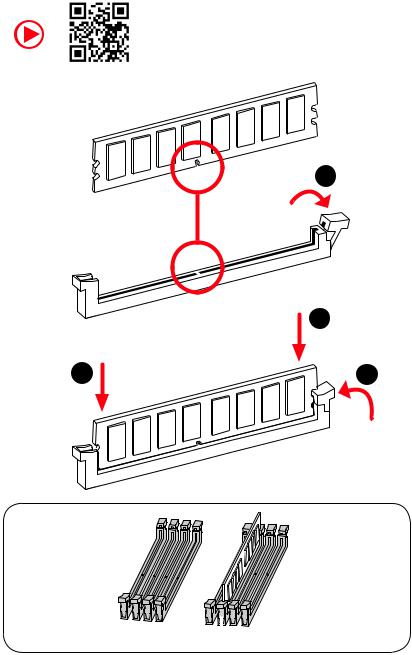
Installing DDR4 memory
http://youtu.be/T03aDrJPyQs
1
|
2 |
2 |
3 |
 DIMMC1
Quick Start 5
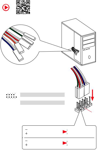
Connecting the Front Panel Header
http://youtu.be/DPELIdVNZUI
|
|
- |
|
|
|
LED |
|
|
LED+ |
POWER |
|
|
POWER |
||
|
LED |
|
|
SW |
HDD |
||
|
|
||
POWER |
|
|
|
SW |
|
|
|
RESET |
|
|
|
2 |
|
|
|
10 |
|
1 |
HDD LED + |
2 |
Power LED + |
|
|
|
|
|
|
|
|
|
|||
|
|
|
3 |
HDD LED - |
4 |
Power LED - |
||||
|
|
|
|
|
|
|
||||
|
|
|
|
|
|
|
|
|
|
|
|
|
|
|
|
|
|
5 |
Reset Switch |
6 |
Power Switch |
1 |
|
|
|
9 |
|
|||||
|
|
|
|
|
|
|
|
|||
|
|
JFP1 |
|
|
7 |
Reset Switch |
8 |
Power Switch |
||
|
|
|
|
|
|
|
|
|||
|
|
|
|
9 |
Reserved |
10 |
No Pin |
|||
|
|
|
|
|
|
|
||||
|
|
|
|
|
|
|
|
|
|
|
RESETSW
HDDLED
|
HDD LED |
|
|
|
|
|
HDD LED - |
|
|
|
|
|
|
||
|
|
|
|
|
|
|
HDD LED + |
|
|
|
|
|
|
|
|
|
|
|
|
|
|
|
POWER LED - |
|
|
|
|
|
|
|
|
|
POWER LED |
|
|
|
|
|
POWER LED + |
|
|
|
|
|
|
|
6 Quick Start
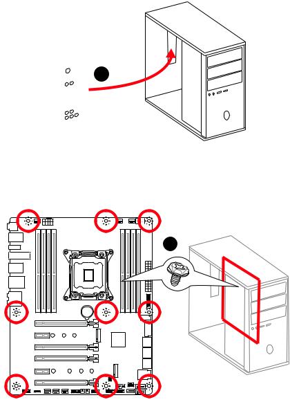
Installing the Motherboard
1
2
BAT1
Quick Start 7
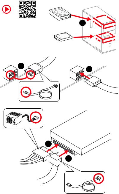
Installing SATA Drives
http://youtu.be/RZsMpqxythc |
1 |
|
2 |
3 |
|
5
 4
4
8 Quick Start
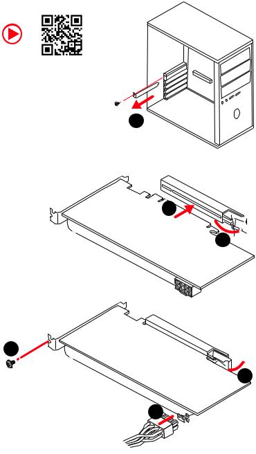
Installing a Graphics Card
http://youtu.be/mG0GZpr9w_A
1
3
2 
5
 4
4
6 

Quick Start 9
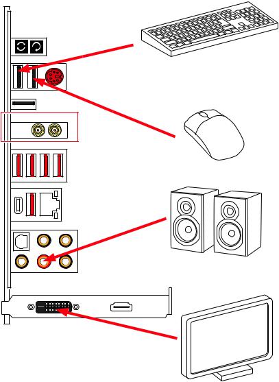
Connecting Peripheral Devices
(Optional) |
10 Quick Start
Connecting the Power Connectors
http://youtu.be/gkDYyR_83I4
ATX_PWR1 |
CPU_PWR1 |
|
Quick Start 11
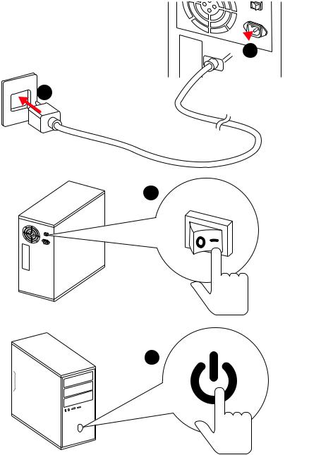
Power On
 1
1
2
3
4
12 Quick Start
Contents |
|
Unpacking.............................................................................................................. |
1 |
Safety Information................................................................................................. |
2 |
Quick Start ............................................................................................................. |
3 |
Preparing Tools and Components.......................................................................... |
3 |
Installing a Processor............................................................................................. |
4 |
Installing DDR4 memory ........................................................................................ |
5 |
Connecting the Front Panel Header....................................................................... |
6 |
Installing the Motherboard..................................................................................... |
7 |
Installing SATA Drives............................................................................................. |
8 |
Installing a Graphics Card ...................................................................................... |
9 |
Connecting Peripheral Devices ............................................................................ |
10 |
Connecting the Power Connectors....................................................................... |
11 |
Power On............................................................................................................... |
12 |
Specifications....................................................................................................... |
16 |
Block Diagram .................................................................................................... |
22 |
Rear I/O Panel ..................................................................................................... |
23 |
LAN Port LED Status Table................................................................................... |
23 |
Audio Ports Configuration .................................................................................... |
23 |
Realtek HD Audio Manager .................................................................................. |
24 |
Installing Antennas (Optional).............................................................................. |
26 |
Overview of Components .................................................................................... |
27 |
CPU Socket ........................................................................................................... |
29 |
DIMM Slots............................................................................................................ |
30 |
PCI_E1~6: PCIe Expansion Slots.......................................................................... |
33 |
PCIe slots bandwidth table................................................................................... |
33 |
U2_1: U.2 Connector............................................................................................. |
36 |
M2_1~2: M.2 Slots (Key M) ................................................................................... |
37 |
SATA1~8: SATA 6Gb/s Connectors ....................................................................... |
38 |
CPU_PWR1, ATX_PWR1: Power Connectors ....................................................... |
40 |
VRAID1: Virtual RAID on CPU Connector ............................................................. |
40 |
JFP1, JFP2: Front Panel Connectors ................................................................... |
41 |
JUSB3, JUSB4: USB 3.1 Gen1 Connectors........................................................... |
41 |
JUSB5: USB 3.1 Gen2 Type-C Connector............................................................. |
42 |
JUSB1~2: USB 2.0 Connectors............................................................................. |
43 |
JTPM1: TPM Module Connector........................................................................... |
43 |
Contents 13
CPU_FAN1, PUMP_FAN1, SYS_FAN1~4: Fan Connectors................................... |
44 |
JTBT1: Thunderbolt Add-on Card Connector ...................................................... |
44 |
JAUD1: Front Audio Connector ............................................................................ |
45 |
JCI1: Chassis Intrusion Connector....................................................................... |
45 |
BIOS_SW1: Multi-BIOS Switch ............................................................................. |
46 |
JBAT1: Clear CMOS (Reset BIOS) Jumper ........................................................... |
47 |
POWER1, RESET1: Power Button, Reset Button ................................................. |
47 |
JLED1: RGB LED connector ................................................................................. |
48 |
Onboard LEDs...................................................................................................... |
49 |
EZ Debug LEDs ..................................................................................................... |
49 |
DIMM LEDs ........................................................................................................... |
49 |
XMP LED ............................................................................................................... |
49 |
Fan LEDs............................................................................................................... |
50 |
PCIe x16 slot LEDs................................................................................................ |
50 |
Debug Code LED................................................................................................... |
51 |
Debug Code LED Table ......................................................................................... |
51 |
ACPI States Codes ................................................................................................ |
53 |
CPU Temperature ................................................................................................. |
53 |
BIOS Setup........................................................................................................... |
54 |
Entering BIOS Setup............................................................................................. |
54 |
Resetting BIOS...................................................................................................... |
55 |
Updating BIOS....................................................................................................... |
55 |
EZ Mode ................................................................................................................ |
57 |
Advanced Mode .................................................................................................... |
59 |
SETTINGS.............................................................................................................. |
60 |
Advanced............................................................................................................... |
60 |
Boot....................................................................................................................... |
65 |
Security................................................................................................................. |
66 |
Save & Exit............................................................................................................ |
67 |
OC.......................................................................................................................... |
68 |
M-FLASH .............................................................................................................. |
74 |
OC PROFILE.......................................................................................................... |
75 |
Software Description........................................................................................... |
76 |
Installing Windows® 10......................................................................................... |
76 |
Installing Drivers .................................................................................................. |
76 |
Installing Utilities ................................................................................................. |
76 |
APP MANAGER ..................................................................................................... |
77 |
LIVE UPDATE 6...................................................................................................... |
78 |
COMMAND CENTER ............................................................................................. |
80 |
14 Contents
GAMING APP......................................................................................................... |
84 |
X-BOOST ............................................................................................................... |
89 |
MYSTICLIGHT........................................................................................................ |
91 |
MSI SMART TOOL ................................................................................................. |
93 |
RAMDISK............................................................................................................... |
95 |
GAMING LAN MANAGER ...................................................................................... |
96 |
DRAGON EYE ........................................................................................................ |
98 |
Nahimic 2.............................................................................................................. |
99 |
XSplit Gamecaster V2 ......................................................................................... |
103 |
SteelSeries Engine 3 .......................................................................................... |
107 |
Intel® Extreme Tuning Utility.............................................................................. |
109 |
CPU-Z.................................................................................................................. |
110 |
TriDef VR ............................................................................................................. |
111 |
TriDef SmartCam................................................................................................ |
114 |
RAID Configuration............................................................................................ |
115 |
Using Intel® Rapid Storage Technology Option ROM ......................................... |
115 |
Degraded RAID Array ......................................................................................... |
118 |
M.2 PCIe SSD RAID............................................................................................. |
120 |
Intel® Optane™ Memory Configuration ............................................................ |
123 |
System Requirements ....................................................................................... |
123 |
Installing the Intel® Optane™ memory .............................................................. |
123 |
Removing the Intel® Optane™ memory ............................................................. |
125 |
Troubleshooting.................................................................................................. |
126 |
Troubleshooting ................................................................................................ |
127 |
Contents 15

Specifications
CPU |
ySupports Intel® Core™ X-Series Processor Family for |
|
LGA2066 Socket |
||
|
||
|
|
|
Chipset |
Intel® X299 Chipset |
|
|
|
|
|
y8x DDR4 memory slots, support up to 128GB* |
|
|
X-series processor support DDR4 4266+(OC)/ 4133(OC)/ |
|
|
4000(OC)/ 3866 (OC)/ 3733(OC)/ 3600(OC)/ 3466(OC)/ |
|
|
3400(OC)/ 3333(OC)/ 3300(OC)/ 3200(OC)/ 3000(OC)/ |
|
|
2800(OC)/ 2666/ 2400/ 2133 MHz* |
|
Memory |
yQuad channel memory architecture with the CPU that |
|
support 4-channels DDR4** |
||
|
yDual channel memory architecture with the CPU that |
|
|
support 2-channels DDR4** |
|
|
ySupports Intel® Extreme Memory Profile (XMP) |
|
|
* For the latest information about memory, please visit http://www.msi.com |
|
|
** Please refer the DIMM Slots section for more details. |
|
|
|
|
|
y4x PCIe 3.0 x16 slots |
|
|
Support x16/ x4*/ x16/ x8 mode with the 44-lane CPU. |
|
|
Support x16/ x4*/ x8/ x4 modes with the 28-lane CPU. |
|
Expansion Slots |
Support x8/ x4*/ x8/ x0, x8/ x4*/ x4/ x4 modes with the |
|
|
16-lane CPU. |
|
|
y2x PCIe 3.0 x1 slots |
|
|
* The PCI_E3 lanes are supported by PCH. Please refer to page 33 for PCIe slots |
|
|
bandwidth table. |
|
|
|
|
Multi-GPU |
ySupports up to 3-Way AMD® CrossFire™ Technology |
|
ySupports up to 3-Way NVIDIA® SLI™ Technology |
||
|
||
|
|
|
LAN |
1x Intel I219-V Gigabit LAN controller |
|
|
|
|
|
yIntel® Dual Band Wireless-AC 8265 module |
|
|
The Wireless module is pre-install in the M2_3 (Key-E) |
|
Wirsless LAN & |
slot. |
|
Bluetooth® |
Supports Wi-Fi 802.11 a/b/g/n/ac, dual band (2.4GHz, |
|
(Optional) |
5GHz) up to 867 Mbps speed. |
|
|
Supports Dual Mode Bluetooth® 2.1, 2.1+EDR, 3.0, 4.0, |
|
|
BLE, 4.2 |
|
|
|
|
|
Continued on next page |
16 Specifications

|
Continued from previous page |
|
|
|
yRealtek® ALC1220 Codec |
Audio |
y7.1-Channel High Definition Audio |
|
ySupports S/PDIF output |
|
|
|
yASMedia® ASM3142 Chipset |
|
1x USB 3.1 Gen2 (SuperSpeed USB 10Gbps) Type-A port |
|
on the back panel |
|
2x USB 3.1 Gen2 (Super Speed USB 10Gbps) Type-C |
|
ports(1 port on the back panel, 1 port available through |
|
the internal USB connector) |
|
yASMedia® ASM1074 Chipset |
USB |
3x USB 3.1 Gen1 (SuperSpeed USB) Type-A ports on the |
|
back panel |
|
yIntel® X299 Chipset |
|
5x USB 3.1 Gen1 (SuperSpeed USB) ports (1 port on the |
|
back panel, 4 ports available through the internal USB |
|
connectors) |
|
7x USB 2.0 (High-speed USB) ports (3 ports on the |
|
back panel, 4 ports available through the internal USB |
|
connectors) |
|
|
|
Intel® X299 Chipset |
|
y8x SATA 6Gb/s ports* |
|
y2x M.2 slots (Key M)* |
|
Supports up to PCIe 3.0 x4 and SATA 6Gb/s |
|
M2_1 slot supports 2242/ 2260 /2280 storage devices |
|
M2_2 slot supports 2242/ 2260 /2280/ 22110 storage |
Storage |
devices |
|
|
|
Intel Optane™ Memory Ready** |
|
y1x U.2 port * |
|
Supports PCIe 3.0 x4 NVMe storage |
|
ySupports Intel® Smart Response Technology |
|
* PCI_E3 slot, M.2 slots, U.2 port and SATA ports share the same bandwidth. |
|
Please refer to page 38 for PCI_E3/ U.2/ M.2/ SATA Combination table . |
|
** Please refer to page 123 for Intel® Optane™ Memory Configuration. |
|
|
|
Continued on next page |
Specifications 17

Continued from previous page
|
Intel® X299 Chipset |
|
|
ySupports RAID 0, RAID 1, RAID 5 and RAID 10 for SATA |
|
RAID |
storage devices |
|
ySupports RAID 0 and RAID 1 for M.2 storage devices* |
||
|
||
|
* M.2 PCIe RAID volume can be created with M.2/Optane Genie. Please refer to |
|
|
page 120 for M.2 PCIe SSD RAID |
|
|
|
|
|
y1x 24-pin ATX main power connector |
|
|
y1x 8-pin ATX 12V power connector |
|
|
y8x SATA 6Gb/s connectors |
|
|
y3x M.2 slots (Key M x2, Key E x1) |
|
|
y1x U.2 port |
|
|
y2x USB 2.0 connectors (supports additional 4 USB 2.0 |
|
|
ports) |
|
|
y2x USB 3.1 Gen1 connectors (supports additional 4 USB 3.1 |
|
|
Gen1 ports) |
|
|
y1x USB 3.1 Gen2 Type-C port |
|
|
y1x 4-pin CPU fan connector |
|
|
y1x 4-pin Water Pump connector |
|
Internal Connectors |
y4x 4-pin system fan connectors |
|
|
y1x Front panel audio connector |
|
|
y2x Front panel connectors |
|
|
y1x TPM module connector |
|
|
y1x Chassis Intrusion connector |
|
|
y1x Clear CMOS jumper |
|
|
y1x Power button |
|
|
y1x Reset button |
|
|
y1x Multi-BIOS switch |
|
|
y1x RGB LED connector |
|
|
y1x Virtual RAID on CPU connector |
|
|
y1x Thunderbolt Add-on Card Connector |
|
|
|
|
|
Continued on next page |
18 Specifications

|
Continued from previous page |
|
|
|
|
|
y1x Clear CMOS button |
|
|
y1x BIOS Flash back button |
|
|
y1x PS/2 keyboard/ mouse combo port |
|
|
y3x USB 2.0 Type-A ports |
|
Back Panel |
y4x USB 3.1 Gen1 Type-A ports |
|
Connectors |
y1x LAN (RJ45) port |
|
|
||
|
y1x USB 3.1 Gen2 Type-A port |
|
|
y1x USB 3.1 Gen2 Type-C port |
|
|
y1x Optical S/PDIF OUT connector |
|
|
y5x OFC audio jacks |
|
|
|
|
I/O Controller |
NUVOTON NCT6795 Controller Chip |
|
|
|
|
|
yCPU/System temperature detection |
|
Hardware Monitor |
yCPU/System fan speed detection |
|
|
yCPU/System fan speed control |
|
|
|
|
Form Factor |
yATX Form Factor |
|
y12 in. x 9.6 in. (30.5 cm x 24.4 cm) |
||
|
||
|
|
|
|
y2x 128 Mb flash |
|
BIOS Features |
yUEFI AMI BIOS |
|
yACPI 6.0, PnP 1.0a, SM BIOS 3.0 |
||
|
||
|
yMulti-language |
|
|
|
|
|
Continued on next page |
Specifications 19

Continued from previous page
|
yDrivers |
|
|
yAPP MANAGER |
|
|
ySUPER CHARGER |
|
|
yCOMMAND CENTER |
|
|
yLIVE UPDATE 6 |
|
|
yMSI SMART TOOL |
|
|
yDRAGON EYE |
|
|
yGAMING APP |
|
|
yX-BOOST |
|
|
yMYSTIC LIGHT |
|
|
yRAMDISK |
|
Software |
yGAMING LAN Manager |
|
yDPC Latency Tuner |
||
|
||
|
yFAST BOOT |
|
|
yNahimic Audio |
|
|
yXSplit Gamecaster V2 |
|
|
yTridef VR & Smart Cam |
|
|
ySteelSeries Engine 3 |
|
|
yWTFast* |
|
|
yCPU-Z MSI GAMING |
|
|
yIntel® Extreme Tuning Utility |
|
|
yGoogle Chrome™,Google Toolbar, Google Drive |
|
|
yNorton™ Internet Security Solution |
|
|
* This offer is valid for a limited period only, for more information please visit |
|
|
www.msi.com |
|
|
|
|
|
yAudio Boost 4 |
|
|
yNahimic 2 |
|
MSI Special |
yGAMING LAN with Gaming LAN Manager |
|
yTurbo U.2 |
||
Features |
||
yTwin Turbo M.2 |
||
|
||
|
yPump Fan |
|
|
ySmart Fan Control |
|
|
|
|
|
Continued on next page |
20 Specifications
Continued from previous page
MSI Special
Features
yMystic Light
yMystic Light Extension
yGaming DNA with bottom LED
yMystic light SYNC
yEZ DEBUG LED
yM.2 Shield FROZR
yPCI-E Steel Armor
yU.2 Steel Armor
yVR Cover
yMuitl GPU - SLI Technology
yMuitl GPU - CrossFire Technology
yDDR4 Boost
yOC Engine (Clock gen)
yUSB with type A+C
yLightning USB with ASM3142
yFront Lightning USB 3.1 Gen type C
yMilitary Class 6
y7000+ Quality Test
yVR Boost
yVR Ready
yIntel WiFi (optional)
yGAMING HOTKEY
yGAMING MOUSE Control
yClick BIOS 5
yBIOS FLASHBACK+
yDual BIOS
yQuadro SLI Ready
yQuadro Ready
yGAMING Certified
ySteelSeries Certified
Specifications 21
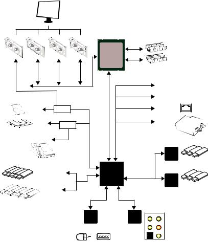
Block Diagram
|
|
|
2/ 4 Channel DDR4 Memory |
||
|
|
|
Processor |
|
|
|
PCI Express Bus |
|
|
PCIe x1 slot |
|
|
|
|
|
||
|
|
|
|
|
PCIe x1 slot |
1x U.2 |
Switch |
|
|
|
Intel I219-V |
2x M.2 |
Switch |
DMI 3.0 |
|
|
Wi-Fi / |
|
|
|
Bluetooth |
||
|
|
|
|
|
|
|
|
|
|
|
(Optional) |
8x SATA 6Gb/s |
|
Bus PCIE |
PCIE Bus |
|
|
|
|
|
ASMEDIA |
||
|
|
|
|
|
ASM3142 |
|
|
|
X299 PCH |
|
|
5x USB 3.1 Gen1 |
|
PCIE Bus |
|
|
|
|
|
|
|
|
ASMEDIA |
|
|
|
|
|
ASM1074 |
7x USB 2.0 |
LPC Bus |
|
|
|
|
|
|
|
|
|
|
|
|
NV6795 |
Realtek |
CS-Out |
Line-In/ SS-Out |
|
|
Super I/O |
ALC1220 |
|
|
|
|
|
|
RS-Out Line-Out |
|
|
PS/2 Mouse / Keyboard |
S/PDIF-Out |
MIC |
||
|
|
|
|
||
3x USB 3.1 Gen2
3x USB 3.1 Gen1
22 Block Diagram
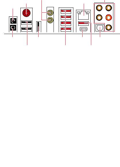
Rear I/O Panel
Wi-Fi Antenna |
|
connectors (Optional) |
Audio Ports |
Clear CMOS |
PS/2 |
LAN |
|
|
|
button |
|
|
BIOS FLASHBACK+ |
USB 2.0/ |
|
USB 3.1 Gen2 Optical |
|
button |
BIOS FLASHBACK+ |
Type-C |
S/PDIF-Out |
|
USB 2.0 |
USB 3.1 Gen1 |
USB 3.1 Gen2 |
||
|
|
Type-A |
|
Type-A |
yClear CMOS button - Power off your computer. Press and hold the Clear CMOS button for about 5-10 seconds to reset BIOS to default values.
yBIOS FLASHBACK+ port/ button - Please refer to page 56 for Updating BIOS with BIOS FLASHBACK+.
LAN Port LED Status Table
Link/ Activity LED
Status |
Description |
|
|
Off |
No link |
|
|
Yellow |
Linked |
|
|
Blinking |
Data activity |
|
|
Speed LED
Status |
Description |
|
|
Off |
10 Mbps connection |
|
|
Green |
100 Mbps connection |
|
|
Orange |
1 Gbps connection |
|
|
Audio Ports Configuration
|
|
|
|
|
|
|
|
|
|
Audio Ports |
|
Channel |
|
|
|
|
|
|
|
|
|
|
|
|
|
|
|||
|
|
|
|
|
|
|
|
|
|
|
|
|
|
|
|
|
|
|
|
|
|
|
|
|
|
2 |
4 |
6 |
8 |
|
|
|
|
|
|
|
|
|
|
|
|
|
|
|
|
|
|
|
|
|
|
|
|
|
Center/ Subwoofer Out |
|
|
● |
● |
|
|
|
|
|
|
|
|
|
|
|
||||
|
|
|
|
|
|
|
|
|
|
Rear Speaker Out |
|
● |
● |
● |
|
|
|
|
|
|
|
|
|
|
|
||||
|
|
|
|
|
|
|
|
|
|
Line-In/ Side Speaker Out |
|
|
|
● |
|
|
|
|
|
|
|
|
|
|
|
|
|||
|
|
|
|
|
|
|
|
|
|
Line-Out/ Front Speaker Out |
● |
● |
● |
● |
|
|
|
|
|
|
|
|
|
|
|||||
|
|
|
|
|
|
|
|
|
|
Mic In |
|
|
|
|
|
|
|
|
|
|
|
|
|
|
|
|
|
||
|
|
|
|
|
|
|
|
|
|
|
|
|
|
|
|
|
|
|
|
|
|
|
|
|
(●: connected, Blank: empty) |
|
|
|
|
Rear I/O Panel 23
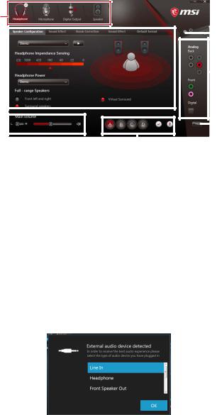
Realtek HD Audio Manager
After installing the Realtek HD Audio driver, the Realtek HD Audio Manager icon will appear in the system tray. Double click on the icon to launch.
Device
Selection
|
|
|
|
|
|
|
|
|
|
|
|
|
|
|
Advanced |
|
|
|
|
|
|
|
|
|
|
|
|
|
|
|
|
|
|
|
|
|
|
|
|
|
|
|
|
|
|
|
Settings |
|
|
|
|
|
|
|
|
|
|
|
|
||||
Application |
|
|
|
|
|
|
|
|
|
|
|
|
|
|
Jack Status |
|
|
|
|
|
|
|
|
|
|
|
|||||
|
|
|
|
|
|
|
|
|
|
|
|
|
|||
Enhancement |
|
|
|
|
|
|
|
|
|
|
|
|
|
||
Main Volume |
|
|
|
|
|
|
|
|
|
|
|
|
|
|
Connector |
|
|
|
|
|
|
|
|
|
|
|
|
|
|
||
|
|
|
|
|
|
|
|
|
|
|
|
|
|
||
|
|
|
|
|
|
|
|
|
|
|
|
|
|
Strings |
|
|
|
|
|
|
|
|
|
|
|
|
|
|
|
|
|
|
|
|
|
|
|
|
|
|
|
|
|
|
|
||
|
|
|
|
|
|
|
Profiles |
||||||||
|
|
|
|
|
|
|
|||||||||
yDevice Selection - allows you to select a audio output source to change the related options. The check sign indicates the devices as default.
yApplication Enhancement - the array of options will provide you a complete guidance of anticipated sound effect for both output and input device.
yMain Volume - controls the volume or balance the right/left side of the speakers that you plugged in front or rear panel by adjust the bar.
yProfiles - toggles between profiles.
yAdvanced Settings - provides the mechanism to deal with 2 independent audio streams.
yJack Status - depicts all render and capture devices currently connected with your computer.
yConnector Settings - configures the connection settings.
Auto popup dialog
When you plug into a device at an audio jack, a dialogue window will pop up asking you which device is current connected.
Each jack corresponds to its default setting as shown on the next page.
24 Rear I/O Panel
Audio jacks to headphone and microphone diagram
Audio jacks to stereo speakers diagram
AUDIO INPUT
Audio jacks to 7.1-channel speakers diagram
AUDIO INPUT
Rear |
Front |
Side |
Center/ |
|
Subwoofer |
Rear I/O Panel 25
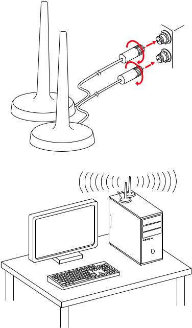
Installing Antennas (Optional)
1. Screw the antennas tight to the Wi-Fi antenna connectors as shown.
2. Place the antennas as high as possible.
26 Rear I/O Panel
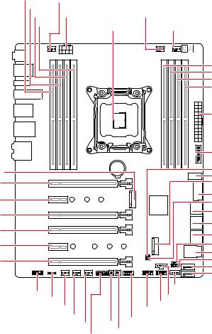
Overview of Components
M2_1 PCI_E1
PCI_E2
PCI_E3
PCI_E4
PCI_E5
PCI_E6
DIMMB1 SYS_FAN1 |
|
|
|
|
DIMMB2 |
|
|
|
|
DIMMA1 CPU_PWR1 |
|
PUMP_FAN1 |
||
DIMMA2 |
CPU Socket |
CPU_FAN1 |
||
|
||||
|
|
|
DIMMC2 |
|
|
|
|
DIMMC1 |
|
|
|
|
DIMMD2 |
|
|
|
|
DIMMD1 |
|
|
|
|
ATX_PWR1 |
|
|
|
|
JUSB4 |
|
|
BAT1 |
|
JBAT1 |
|
|
|
|
JUSB5 |
|
|
|
|
M2_2 |
|
|
|
|
JUSB3 |
|
|
|
|
JCI1 |
|
|
|
|
SATA▼1▲2 |
|
|
|
|
SATA▼3▲4 |
|
|
|
|
SATA▼5▲6 |
|
|
|
|
BIOS_SW1 |
|
|
|
|
U2_1 |
|
|
|
|
JFP2 |
|
|
|
|
SATA7 |
|
|
|
|
SATA8 |
|
JAUD1 |
|
|
VRAID1* |
|
|
|
JTBT1 |
||
JLED1 |
|
|
||
|
|
JUSB2 JUSB1 |
||
SYSFAN4 |
|
|
||
SYSFAN3 |
POWER1 |
JFP1 |
||
SYSFAN2 |
||||
|
|
|||
|
RESET1 |
|
||
JTPM1 |
|
|
||
Overview of Components 27

Component Contents
Port Name |
Port Type |
Page |
|
|
|
|
|
BIOS_SW1 |
Multi-BIOS Switch |
46 |
|
|
|
|
|
CPU_FAN1, PUMP_FAN1, SYS_FAN1~4 |
Fan Connectors |
44 |
|
|
|
|
|
CPU_PWR1, ATX_PWR1 |
Power Connectors |
40 |
|
|
|
|
|
CPU Socket |
LGA2066 |
29 |
|
|
|
|
|
DIMMA1~D2 |
DIMM Slots |
30 |
|
|
|
|
|
JAUD1 |
Front Audio Connector |
45 |
|
|
|
|
|
JBAT1 |
Clear CMOS (Reset BIOS) |
47 |
|
Jumper |
|||
|
|
||
|
|
|
|
JCI1 |
Chassis Intrusion Connector |
45 |
|
|
|
|
|
JFP1, JFP2 |
Front Panel Connectors |
41 |
|
|
|
|
|
JLED1 |
RGB LED connector |
48 |
|
|
|
|
|
JTBT1 |
Thunderbolt Add-on Card |
44 |
|
Connector |
|||
|
|
||
JTPM1 |
TPM Module Connector |
43 |
|
|
|
|
|
JUSB1~2 |
USB 2.0 Connectors |
43 |
|
|
|
|
|
JUSB3, JUSB4 |
USB 3.1 Gen1 Connectors |
41 |
|
|
|
|
|
JUSB5 |
USB 3.1 Gen2 Type-C Connector |
42 |
|
|
|
|
|
M2_1~2 |
M.2 Slots (Key M) |
37 |
|
|
|
|
|
PCI_E1~6 |
PCIe Expansion Slots |
33 |
|
|
|
|
|
POWER1, RESET1 |
Power Button, Reset Button |
47 |
|
|
|
|
|
SATA1~8 |
SATA 6Gb/s Connectors |
38 |
|
|
|
|
|
U2_1 |
U.2 Connector |
36 |
|
|
|
|
|
VRAID1 |
Virtual RAID on CPU Connector |
40 |
|
|
|
|
28 Overview of Components
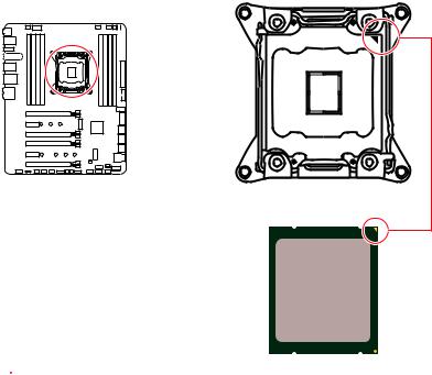
CPU Socket
Introduction to the LGA 2066 CPU
The surface of the LGA2066 CPU has four alignment keys and a yellow triangle to assist in correctly lining up the CPU for motherboard placement. The yellow triangle is the Pin 1 indicator.
 Important
yAlways unplug the power cord from the power outlet before installing or removing the CPU.
yPlease retain the CPU protective cap after installing the processor. MSI will deal with Return Merchandise Authorization (RMA) requests if only the motherboard comes with the protective cap on the CPU socket.
yWhen installing a CPU, always remember to install a CPU heatsink. A CPU heatsink is necessary to prevent overheating and maintain system stability.
yConfirm that the CPU heatsink has formed a tight seal with the CPU before booting your system.
yOverheating can seriously damage the CPU and motherboard. Always make sure the cooling fans work properly to protect the CPU from overheating. Be sure to apply an even layer of thermal paste (or thermal tape) between the CPU and the heatsink to enhance heat dissipation.
yWhenever the CPU is not installed, always protect the CPU socket pins by covering the socket with the plastic cap.
yIf you purchased a separate CPU and heatsink/ cooler, Please refer to the documentation in the heatsink/ cooler package for more details about installation.
yThis motherboard is designed to support overclocking. Before attempting to overclock, please make sure that all other system components can tolerate overclocking. Any attempt to operate beyond product specifications is not recommended. MSI® does not guarantee the damages or risks caused by inadequate operation beyond product specifications.
Overview of Components 29
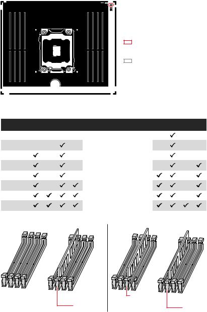
DIMM Slots
S/K LED : S/K LED indicates that the installed CPU supports either 4-channels or 2-channels memory architecture.
Red = 8 DIMMs support (4-channels architecture CPU)
White = 4 DIMMs support (2-channels architecture CPU)
B1B2A1A2 |
BAT1 |
C2C1D2D1 |
Memory module installation recommendation (4-Channels architecture CPU )
|
B1 |
B2 |
A1 |
A2 |
Intel Core X-series CPU |
C2 |
C1 |
D2 |
D1 |
|
|
|
|
|
|
|
|
|
|
1 DIMM |
|
|
|
|
|
|
|
|
|
|
|
|
|
|
|
|
|
|
|
2 DIMMs |
|
|
|
|
|
|
|
|
|
|
|
|
|
|
|
|
|
|
|
3 DIMMs |
|
|
|
|
|
|
|
|
|
|
|
|
|
|
|
|
|
|
|
4 DIMMs |
|
|
|
|
Supports 4-channels |
|
|
|
|
|
|
|
|
|
|
|
|
|
|
5 DIMMs |
|
|
|
|
memory architecture |
|
|
|
|
|
|
|
|
|
|
|
|
|
|
|
|
|
|
|
|
|
|
|
|
6 DIMMs |
|
|
|
|
|
|
|
|
|
|
|
|
|
|
|
|
|
|
|
7 DIMMs |
|
|
|
|
|
|
|
|
|
|
|
|
|
|
|
|
|
|
|
8 DIMMs |
|
|
|
|
|
|
|
|
|
|
|
|
|
|
|
|
|
|
|
|
DIMMA1 |
DIMMC1 |
DIMMC1 |
|
30 Overview of Components
Loading...