


 Loading...
Quick Start
Thank you for purchasing the MSI® Z390-A PRO motherboard. This Quick Start section provides demonstration diagrams about how to install your computer. Some of the installations also provide video demonstrations. Please link to the URL to watch it with the web browser on your phone or tablet. You may have even link to the URL by scanning the QR code.
Preparing Tools and Components
Intel® LGA 1151 CPU
CPU Fan
Chassis
DDR4 Memory
Power Supply Unit |
Graphics Card |
Thermal Paste
SATA Hard Disk Drive |
SATA DVD Drive |
|
Phillips Screwdriver |
A Package of Screws |
Quick Start 1

Installing a Processor |
2 |
|
https://youtu.be/4ce91YC3Oww |
1 |
3
|
7 |
|
4 |
5 |
9 |
|
6 
8
2 Quick Start
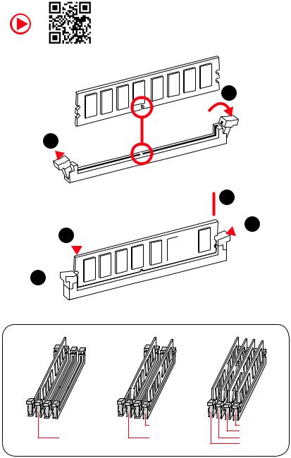
Installing DDR4 memory
http://youtu.be/T03aDrJPyQs
1
1 
2
 3 2
3 2 


3 


|
DIMMB2 |
DIMMB2 |
|
|
DIMMB1 |
DIMMA2 |
DIMMA2 |
DIMMA2 |
|
|
DIMMA1 |
Quick Start 3
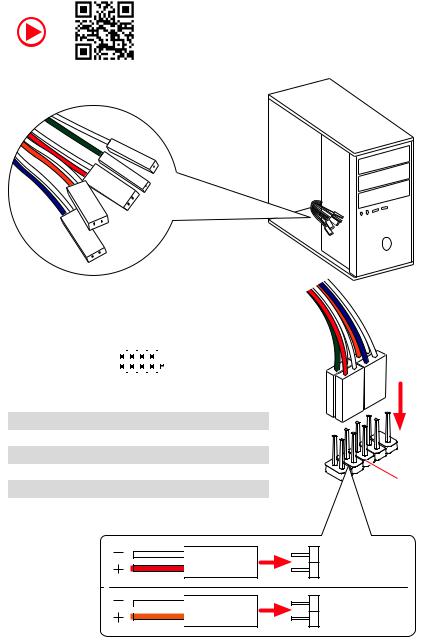
Connecting the Front Panel Header
http://youtu.be/DPELIdVNZUI
|
|
- |
|
|
|
LED |
|
|
LED+ |
POWER |
|
|
POWER |
||
|
LED |
|
|
SW |
HDD |
||
|
|
||
POWER |
|
|
|
SW |
|
|
|
RESET |
|
|
|
|
|
|
|
|
|
|
|
|
|
||||||||
|
|
Power LED |
|
Power Switch |
|||||||||||||
|
|
|
|
|
|
|
|
|
|
|
|
|
|
|
|
|
|
|
|
|
|
|
|
|
|
|
|
|
|
|
|
|
|
|
|
|
|
|
|
+ - + - |
|
|
|
|
|
|
|||||||
|
JFP1 |
2 |
|
|
|
|
|
|
|
|
|
10 |
|
|
|||
|
|
|
|
|
|
|
|
|
|
||||||||
|
1 |
|
|
|
|
|
|
|
|
|
9 |
|
|
||||
|
|
|
|
|
|
|
|
|
|
|
|
|
|
|
|||
|
|
|
|
+ - - + |
|
|
|
Reserved |
|||||||||
|
|
|
|
|
|
|
|
|
|
|
|
|
|
|
|
|
|
|
|
|
|
|
|
|
|
|
|
|
|
||||||
|
|
|
|
|
|
|
|
|
|
|
|||||||
|
|
|
HDD LED |
|
|
|
Reset Switch |
||||||||||
|
|
|
|
|
|
|
|
|
|
|
|
|
|
|
|
|
|
1 |
HDD LED + |
|
|
|
|
2 |
|
|
|
|
|
Power LED + |
|||||
|
|
|
|
|
|
|
|
|
|
|
|
|
|
|
|
|
|
3 |
HDD LED - |
|
|
|
|
4 |
|
|
|
|
|
Power LED - |
|||||
|
|
|
|
|
|
|
|
|
|
|
|
|
|
|
|
|
|
5 |
Reset Switch |
|
|
|
|
6 |
|
|
|
|
|
Power Switch |
|||||
|
|
|
|
|
|
|
|
|
|
|
|
|
|
|
|
|
|
7 |
Reset Switch |
|
|
|
|
8 |
|
|
|
|
|
Power Switch |
|||||
|
|
|
|
|
|
|
|
|
|
|
|
|
|
|
|
|
|
9 |
Reserved |
|
|
|
|
10 |
|
|
|
|
|
No Pin |
|||||
|
|
|
|
|
|
|
|
|
|
|
|
|
|
|
|
|
|
HDD LED
 POWER LED
RESETSW
HDDLED
HDD LED - HDD LED +
POWER LED - POWER LED +
4 Quick Start
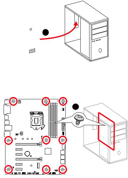
Installing the Motherboard
1
2
BAT1
Quick Start 5
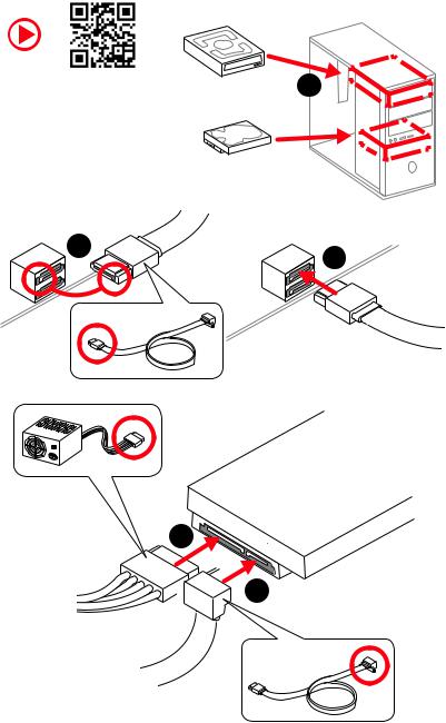
Installing SATA Drives
http://youtu.be/RZsMpqxythc |
1 |
|
2 |
3 |
|
5
 4
4
6 Quick Start
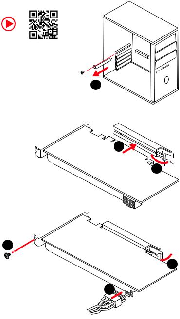
Installing a Graphics Card
http://youtu.be/mG0GZpr9w_A
1
3
2 
5
 4
4
6 

Quick Start 7
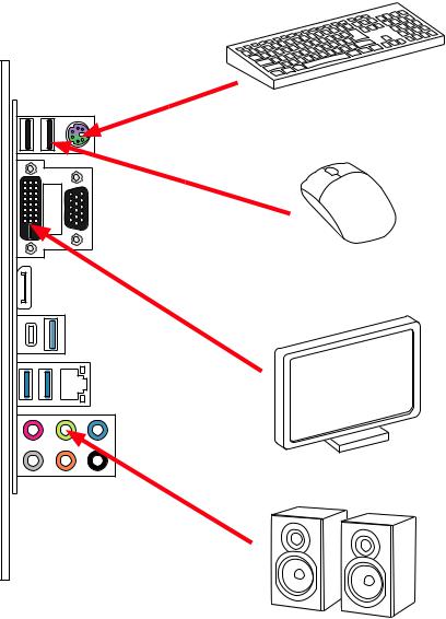
Connecting Peripheral Devices
8 Quick Start
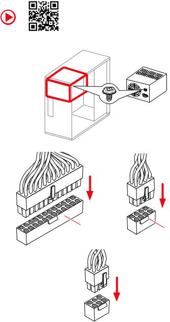
Connecting the Power Connectors
http://youtu.be/gkDYyR_83I4
ATX_PWR1 |
CPU_PWR1 |
|
PCIE_PWR1
Quick Start 9
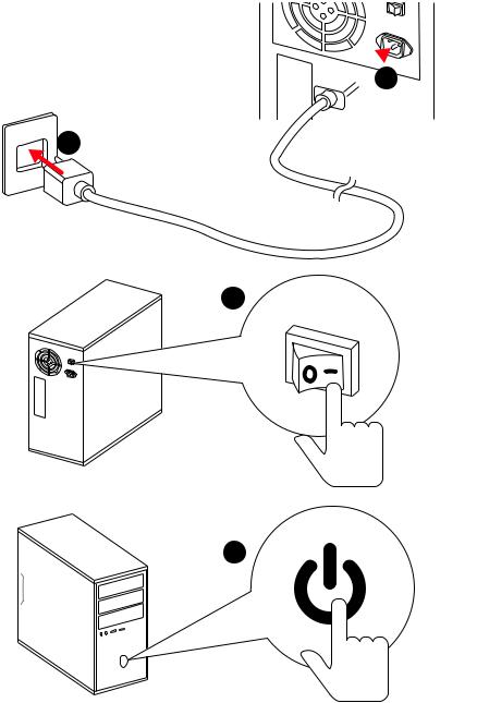
Power On
 1
1
2
3
4
10 Quick Start
Contents |
|
Quick Start ............................................................................................................. |
1 |
Preparing Tools and Components.......................................................................... |
1 |
Installing a Processor............................................................................................. |
2 |
Installing DDR4 memory ........................................................................................ |
3 |
Connecting the Front Panel Header....................................................................... |
4 |
Installing the Motherboard..................................................................................... |
5 |
Installing SATA Drives............................................................................................. |
6 |
Installing a Graphics Card ...................................................................................... |
7 |
Connecting Peripheral Devices .............................................................................. |
8 |
Connecting the Power Connectors......................................................................... |
9 |
Power On............................................................................................................... |
10 |
Specifications....................................................................................................... |
13 |
Package contents ................................................................................................ |
18 |
Block Diagram .................................................................................................... |
19 |
Rear I/O Panel ..................................................................................................... |
20 |
LAN Port LED Status Table................................................................................... |
20 |
Audio Ports Configuration .................................................................................... |
20 |
Realtek Audio Console ......................................................................................... |
21 |
Overview of Components .................................................................................... |
23 |
CPU Socket ........................................................................................................... |
25 |
DIMM Slots............................................................................................................ |
26 |
PCI_E1~6: PCIe Expansion Slots.......................................................................... |
27 |
SATA1~6: SATA 6Gb/s Connectors ....................................................................... |
27 |
M2_1: M.2 Slot (Key M) ......................................................................................... |
28 |
JTPM1: TPM Module Connector........................................................................... |
28 |
JFP1, JFP2: Front Panel Connectors ................................................................... |
29 |
JCOM1: Serial Port Connector ............................................................................. |
29 |
JTBT1: Thunderbolt Add-on Card Connector ...................................................... |
29 |
CPU_PWR1, ATX_PWR1, PCIE_PWR1: Power Connectors.................................. |
30 |
JUSB3~4: USB 3.1 Gen1 Connectors ................................................................... |
31 |
JUSB1~2: USB 2.0 Connectors............................................................................. |
32 |
JLPT1: Parallel Port Connector ........................................................................... |
32 |
CPU_FAN1, PUMP_FAN1, SYS_FAN1~5: Fan Connectors................................... |
33 |
JAUD1: Front Audio Connector ............................................................................ |
34 |
JCI1: Chassis Intrusion Connector....................................................................... |
34 |
JBAT1: Clear CMOS (Reset BIOS) Jumper ........................................................... |
35 |
JOC1: Front OC Button Connector ....................................................................... |
35 |
Contents 11
JRGB1: RGB LED connector................................................................................. |
36 |
EZ Debug LED....................................................................................................... |
36 |
Installing OS, Drivers & Utilities ......................................................................... |
37 |
Installing Windows® 10......................................................................................... |
37 |
Installing Drivers .................................................................................................. |
37 |
Installing Utilities ................................................................................................. |
37 |
MYSTIC LIGHT...................................................................................................... |
38 |
Device LED effect control screen ......................................................................... |
38 |
BIOS Setup........................................................................................................... |
41 |
Entering BIOS Setup............................................................................................. |
41 |
Resetting BIOS...................................................................................................... |
42 |
Updating BIOS....................................................................................................... |
42 |
EZ Mode ................................................................................................................ |
43 |
Advanced Mode .................................................................................................... |
45 |
SETTINGS.............................................................................................................. |
46 |
Advanced............................................................................................................... |
46 |
Boot....................................................................................................................... |
53 |
Security................................................................................................................. |
53 |
Save & Exit............................................................................................................ |
54 |
OC.......................................................................................................................... |
56 |
M-FLASH .............................................................................................................. |
62 |
OC PROFILE.......................................................................................................... |
63 |
HARDWARE MONITOR.......................................................................................... |
64 |
RAID Configuration.............................................................................................. |
65 |
Enabling Intel® Rapid Storage Technology .......................................................... |
65 |
Creating RAID Volume ......................................................................................... |
66 |
Removing a RAID Volume .................................................................................... |
67 |
Resetting Disks to Non-RAID ............................................................................... |
68 |
Rebuilding RAID Array.......................................................................................... |
69 |
Installing RAID Driver........................................................................................... |
70 |
Installing Intel® Rapid Storage Technology Software .......................................... |
70 |
Intel® Optane™ Memory Configuration .............................................................. |
71 |
System Requirements ......................................................................................... |
71 |
Installing the Intel® Optane™ memory ................................................................ |
71 |
Removing the Intel® Optane™ memory ............................................................... |
73 |
Troubleshooting .................................................................................................. |
74 |
Regulatory Notices.............................................................................................. |
75 |
12 Contents

Specifications
|
Supports Intel® Core™ 9000 Series family/ 8th Gen Intel® |
|
CPU |
Core™ / Pentium® Gold / Celeron® processors for LGA 1151 |
|
socket |
||
|
* Please go to www.intel.com for more compatibility information. |
|
|
|
|
Chipset |
Intel® Z390 Chipset |
|
|
y4x DDR4 memory slots, support up to 64GB* |
|
|
ySupports DDR4 4400(OC)/ 4300(OC)/ 4266(OC)/ 4200(OC)/ |
|
|
4133(OC)/ 4000(OC)/ 3866(OC)/ 3733(OC)/ 3600(OC)/ |
|
|
3466(OC)/ 3400(OC)/ 3333(OC)/ 3300(OC)/ 3200(OC)/ 3000(OC) |
|
Memory |
/ 2800(OC)/ 2666/ 2400/ 2133 MHz* |
|
ySupports Dual-Channel mode |
||
|
||
|
ySupports non-ECC, un-buffered memory |
|
|
ySupports Intel® Extreme Memory Profile (XMP) |
|
|
* Please refer www.msi.com for more information on compatible memory. |
|
|
|
|
|
y2x PCIe 3.0 x16 slots |
|
Expansion Slot |
y4x PCIe 3.0 x1 slots |
|
y1 x M.2 slot with E key for Integrated Intel® Wireless-AC |
||
|
||
|
(CNVi) module only |
|
|
|
|
|
y1x VGA port, supports a maximum resolution of |
|
|
2048x1536@50Hz, 2048x1280@60Hz, 1920x1200@60Hz |
|
Onboard Graphics |
y1x DVI-D port, supports a maximum resolution of |
|
1920x1200@60Hz |
||
|
||
|
y1x DisplayPort, supports a maximum resolution of |
|
|
4096x2304@60Hz |
|
|
|
|
Multi-GPU |
ySupports 2-Way AMD® CrossFire™ Technology |
|
|
Intel® Z390 Chipset |
|
|
y6x SATA 6Gb/s ports* |
|
|
y1x M.2 slot (Key M) |
|
Storage |
Supports up to PCIe 3.0 x4 and SATA 6Gb/s, 2242/ 2260/ |
|
2280/ 22110 storage devices |
||
|
||
|
Intel® Optane™ Memory Ready** |
|
|
* The SATA2 will be unavailable when installing M.2 SATA device into M.2 slot. |
|
|
** Before using Intel® Optane™ memory modules, please ensure that you have |
|
|
updated the drivers and BIOS to the latest version from MSI website. |
|
|
|
|
|
Continued on next page |
Specifications 13

|
Continued from previous page |
|
|
|
|
|
Intel® Z390 Chipset |
|
RAID |
ySupports RAID 0, RAID1, RAID 5 and RAID 10 for SATA |
|
|
storage devices |
|
|
|
|
LAN |
y1x Intel® I219-V Gigabit LAN controller |
|
|
|
|
|
yIntel® Z390 Chipset |
|
|
2x USB 3.1 Gen2 (SuperSpeed USB 10Gbps) ports (1x |
|
|
Type-A port and 1x Type-C port) on the back panel |
|
|
6x USB 3.1 Gen1 (SuperSpeed USB) ports (2 Type-A |
|
USB |
ports on the back panel, 4 ports available through the |
|
internal USB 3.1 connectors) |
||
|
6x USB 2.0 (High-speed USB) ports (2 Type-A ports on |
|
|
the back panel, 4 ports available through the internal |
|
|
USB 2.0 connectors)* |
|
|
* The CNVI_1 and JUSB2 share the same bandwidth. Please refer to page 32 for |
|
|
details. |
|
|
|
|
Audio |
yRealtek® ALC892 Codec |
|
7.1-Channel High Definition Audio |
||
|
||
|
|
|
|
y1x PS/2 keyboard/ mouse combo port |
|
|
y2x USB 2.0 Type-A ports |
|
|
y1x VGA port |
|
|
y1x DVI-D port |
|
Back Panel |
y1x DisplayPort |
|
Connectors |
y1x USB 3.1 Gen2 Type-A port |
|
|
||
|
y1x USB 3.1 Gen2 Type-C port |
|
|
y1x LAN (RJ45) port |
|
|
y2x USB 3.1 Gen1 Type-A ports |
|
|
y6x audio jacks |
|
|
|
|
|
Continued on next page |
14 Specifications

Continued from previous page
y1x 24-pin ATX main power connector
y1x 8-pin ATX 12V power connector
y1x 6-pin ATX 12V power connector
y6x SATA 6Gb/s connectors
y2x M.2 slots (1 M-Key slot,1 E-Key slot)
y2x USB 3.1 Gen1 connectors (supports additional 4 USB 3.1 Gen1 ports)
y2x USB 2.0 connectors (supports additional 4 USB 2.0 ports)
y1x 4-pin CPU fan connector
y1x 4-pin Water Pump connector
Internal Connectors y5x 4-pin system fan connectors
y1x Front panel audio connector
y2x System panel connectors
y1x Chassis Intrusion connector
y1x 4-pin RGB LED connector
y1x Serial Port connector
y1x Clear CMOS jumper
y1x Parallel port connector
y1x TPM module connector
y1x thunderbolt Add-on card connector
y1x Front OC button connector
I/O Controller |
NUVOTON NCT6797 Controller Chip |
|
|
|
|
|
yCPU/System temperature detection |
|
Hardware Monitor |
yCPU/System fan speed detection |
|
|
yCPU/System fan speed control |
|
|
|
|
Form Factor |
yATX Form Factor |
|
y12 in. x 9.6 in. (30.5 cm x 24.4 cm) |
||
|
||
|
|
|
|
y1x 128 Mb flash |
|
BIOS Features |
yUEFI AMI BIOS |
|
yACPI 6.1, SMBIOS 2.8 |
||
|
||
|
yMulti-language |
|
|
|
|
|
Continued on next page |
Specifications 15

|
Continued from previous page |
|
|
|
|
|
yDrivers |
|
|
yDRAGON CENTER |
|
|
yMYSTIC LIGHT |
|
Software |
yCPU-Z MSI GAMING |
|
|
yIntel® Extreme Tuning Utility |
|
|
yGoogle Chrome™ |
,Google Toolbar, Google Drive |
|
yNorton™ Internet Security Solution |
|
|
|
|
|
yOC Performance |
|
Dragon Center |
yHardware Monitor |
|
yEyerest |
|
|
Features |
|
|
yLAN Manager |
|
|
|
Please refer to http://download.msi. |
|
|
yLive Update |
com/manual/mb/DRAGONCENTER2. |
|
pdf for more details. |
|
|
|
|
|
|
|
|
yAudio |
|
|
Audio Boost |
|
|
yNetwork |
|
|
Intel LAN with Network Manage |
|
|
Intel CNVi Ready |
|
|
yStorage |
|
Special Features |
Turbo M.2 |
|
|
yFan |
|
|
Pump Fan |
|
|
Smart Fan Control |
|
|
yLED |
|
|
Mystic Light Extension (RGB) |
|
|
EZ DEBUG LED |
|
|
|
|
|
Continued on next page |
|
16 Specifications
Continued from previous page
|
yProtection |
|
|
PCI-E Steel Armor |
|
|
PCI-E Steel Slot |
|
|
yPerformance |
|
|
Core Boost |
|
|
OC Genie |
|
Special Features |
Multi GPU-CrossFire Technology |
|
DDR4 Boost |
||
|
||
|
USB with type A+C |
|
|
Intel Turbo USB 3.1 Gen2 |
|
|
yVR |
|
|
VR Ready |
|
|
yBIOS |
|
|
Click BIOS 5 |
|
|
|
Specifications 17
Package contents
Please check the contents of your motherboard package. It should contain:
Motherboard |
Z390-A PRO |
|
|
|
|
|
|
Cable |
SATA 6Gb/s Cables |
2 |
|
|
|
|
|
|
M.2 Screw |
1 |
|
|
|
|
|
Accessories |
I/O Shield |
1 |
|
|
|
||
Case Badge |
1 |
||
|
|||
|
|
|
|
|
VIP Card |
1 |
|
|
|
|
|
Application DVD |
Driver DVD |
1 |
|
|
|
|
|
Documentation |
Quick Installation Guide |
1 |
|
|
|
|
 Important
If any of the above items are damaged or missing, please contact your retailer.
18 Package contents
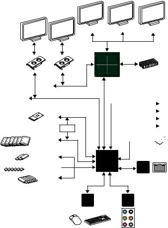
Block Diagram
DisplayPort
PCI Express Bus
x4
PCI Express Bus
1 x M.2 |
|
Switch |
PCI |
|
|
6 x SATA 6Gb/s |
BusExpress |
|
|
2 x USB 3.1 Gen2 |
|

 6 x USB 3.1 Gen1
6 x USB 2.0
LPC Bus
VGA |
DVI-D |
2 Channel DDR4 Memory
CPU
DMI 3.0
x1 |
|
PCIe x1 slot |
x1 |
|
|
|
PCIe x1 slot |
|
x1 |
|
|
|
PCIe x1 slot |
|
x1 |
|
|
|
PCIe x1 slot |
|
|
|
 1x M.2
(E Key for Intel CNVi module only)
chipset
Intel
I219-V
NV6797 |
Realtek |
Super I/O |
ALC892 |
P/S2 Mouse / Keyboard |
Audio Jacks |
|
Block Diagram 19
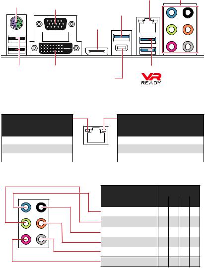
Rear I/O Panel
PS/2 |
|
LAN |
Audio Ports |
VGA |
USB 3.1 Gen2 |
|
|
|
Type-A |
|
|
|
|
|
|
|
|
DisplayPort |
|
USB 2.0 |
DVI-D |
USB 3.1 Gen1 Type-A |
|
|
|
USB 3.1 Gen2 Type-C |
|
LAN Port LED Status Table
Link/ Activity LED
Status |
Description |
|
|
Off |
No link |
|
|
Yellow |
Linked |
|
|
Blinking |
Data activity |
|
|
Speed LED
Status |
Description |
|
|
Off |
10 Mbps connection |
|
|
Green |
100 Mbps connection |
|
|
Orange |
1 Gbps connection |
|
|
Audio Ports Configuration
Audio Ports |
|
Channel |
|
|
|
|
|
|
|
|
|
|
|
|
2 |
4 |
6 |
8 |
|
|
|
|
|
|
Line-In |
|
|
|
|
|
|
|
|
|
Line-Out/ Front Speaker Out ● |
● |
● |
● |
|
Rear Speaker Out |
● |
● |
● |
|
Center/ Subwoofer Out |
|
● |
● |
|
Side Speaker Out |
|
|
● |
|
Mic In
(●: connected, Blank: empty)
20 Rear I/O Panel
Realtek Audio Console
After Realtek Audio Console is installed. You can use it to change sound settings to get better sound experience.
Application Enhancement |
Advanced Settings |
Device 
Selection
 Main Volume
|
|
|
|
|
Connector Settings |
|
|
|
|
Jack Status |
||||
yDevice Selection - allows you to select a audio output source to change the related options. The check sign indicates the devices as default.
yApplication Enhancement - the array of options will provide you a complete guidance of anticipated sound effect for both output and input device.
yMain Volume - controls the volume or balance the right/left side of the speakers that you plugged in front or rear panel by adjust the bar.
yAdvanced Settings - provides the mechanism to deal with 2 independent audio streams.
yJack Status - depicts all render and capture devices currently connected with your computer.
yConnector Settings - configures the connection settings.
Auto popup dialog
When you plug into a device at an audio jack, a dialogue window will pop up asking you which device is current connected.
Each jack corresponds to its default setting as shown on the next page.
Important
The pictures above for reference only and may vary from the product you purchased.
Rear I/O Panel 21
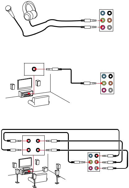
Audio jacks to headphone and microphone diagram
Audio jacks to stereo speakers diagram
AUDIO INPUT
Audio jacks to 7.1-channel speakers diagram
AUDIO INPUT
Front Center/
Subwoofer
Rear |
Side |
22 Rear I/O Panel
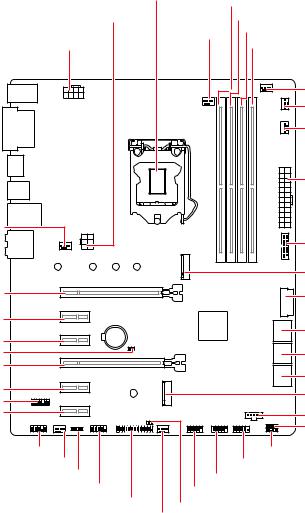
Overview of Components
SYS_FAN1
PCI_E1
PCI_E2
PCI_E3
JBAT1
PCI_E4
PCI_E5
JTPM1
PCI_E6
|
CPU Socket |
|
|
|
|
DIMMA1 |
|
PCIE_PWR1 |
|
|
DIMMA2 |
|
|
CPU_FAN1 |
DIMMB1 |
|
|
|
|
CPU_PWR1 |
|
|
DIMMB2 |
|
|
|
|
|
|
|
PUMP_FAN1 |
|
|
|
SYS_FAN5 |
|
|
|
SYS_FAN4 |
|
|
|
ATX_PWR1 |
|
|
|
JUSB4 |
|
|
|
M2_1 |
|
|
|
JUSB3 |
BAT1 |
|
|
SATA▼1▲2 |
|
|
|
SATA▼3▲4 |
|
|
|
SATA▼5▲6 |
|
|
|
CNVI_1 |
|
|
|
JTBT1 |
|
|
|
JOC1 |
JAUD1 |
|
|
JFP2 |
SYS_FAN2 |
|
|
JFP1 |
JRGB1 |
|
JUSB2 |
|
JCOM1 |
|
|
|
|
JUSB1 |
|
|
|
|
|
|
JLPT1 |
JCI1 |
|
|
|
|
|
|
|
|
SYS_FAN3 |
|
Overview of Components 23

Component Contents
Port Name |
Port Type |
Page |
|
|
|
|
|
CPU_FAN1, PUMP_FAN1, SYS_FAN1~5 |
Fan Connectors |
33 |
|
|
|
|
|
CPU_PWR1, ATX_PWR1, PCIE_PWR1 |
Power Connectors |
30 |
|
|
|
|
|
CPU Socket |
LGA 1151 Socket |
25 |
|
|
|
|
|
DIMMA1/A2/B1/B2 |
DIMM Slots |
26 |
|
|
|
|
|
JAUD1 |
Front Audio Connector |
34 |
|
|
|
|
|
JBAT1 |
Clear CMOS Jumper |
35 |
|
|
|
|
|
JCI1 |
Chassis Intrusion Connector |
34 |
|
|
|
|
|
JCOM1 |
Serial Port Connector |
29 |
|
|
|
|
|
JFP1, JFP2 |
Front Panel Connectors |
29 |
|
|
|
|
|
JLPT1 |
Parallel Port Connector |
32 |
|
|
|
|
|
JOC1 |
Front OC Button Connector |
35 |
|
|
|
|
|
JRGB1 |
RGB LED connector |
36 |
|
|
|
|
|
JTBT1 |
Thunderbolt Add-on Card |
29 |
|
Connector |
|||
|
|
||
JTPM1 |
TPM Module Connector |
28 |
|
|
|
|
|
JUSB1~2 |
USB 2.0 Connectors |
32 |
|
|
|
|
|
JUSB3~4 |
USB 3.1 Gen1 Connectors |
31 |
|
|
|
|
|
M2_1 |
M.2 Slot (Key M) |
28 |
|
|
|
|
|
PCI_E1~6 |
PCIe Expansion Slots |
27 |
|
|
|
|
|
SATA1~6 |
SATA 6Gb/s Connectors |
27 |
|
|
|
|
24 Overview of Components
Loading...