


X58 Pro-E

 series
MS-7522 (v3.x) Mainboard
G52-75221X8
Preface
Copyright Notice
The material in this document is the intellectual property of MICRO-STAR INTERNA - TIONAL.
 We take every care in the preparation of this document, but no guarantee is given as to the correctness of its contents. Our products are under continual improvement and we reserve the right to make changes without notice.
Trademarks
All trademarks are the properties of their respective owners.
MSI® is registered trademark of Micro-Star Int’l Co.,Ltd.
NVIDIA® is registered trademark of NVIDIA Corporation.
ATI® is registered trademark of ATI Technologies, Inc.
AMD® is registered trademarks of AMD Corporation.
Intel® is registered trademarks of Intel Corporation.
Windows® is registered trademarks of Microsoft Corporation.
AMI® is registered trademark of Advanced Micro Devices, Inc.
Award® is a registered trademark of Phoenix Technologies Ltd.
Sound Blaster® is registered trademark of Creative Technology Ltd.
Realtek® is registered trademark of Realtek Semiconductor Corporation.
JMicron® is registered trademark of JMicron Technology Corporation.
Netware® is a registered trademark of Novell, Inc.
Revision |
History |
|
Revision |
Revision History |
Date |
V3.1 |
First release for X58 Pro-E for Europe |
April 2009 |
Technical
 Support
If a problem arises with your system and no solution can be obtained from the user’s manual, please contact your place of purchase or local distributor. Alternatively, please try the following help resources for further guidance.
◙Visit the MSI website for FAQ, technical guide, BIOS updates, driver updates, and other information: http://www.msi.com/index.php?func=service
◙Contact our technical staff at: http://ocss.msi.com
ii
MS-7522
Safety Instructions
Always read the safety instructions carefully.
Keep this User’s Manual for future reference.
Keep this equipment away from humidity.
Lay this equipment on a reliable flat surface before setting it up.
The openings on the enclosure are for air convection hence protects the equipment from overheating. DO NOT COVER THE OPENINGS.
Make sure the voltage of the power source and adjust properly 110/220V before connecting the equipment to the power inlet.
Place the power cord such a way that people can not step on it. Do not place anything over the power cord.
Always Unplug the Power Cord before inserting any add-on card or module.
All cautions and warnings on the equipment should be noted.
Never pour any liquid into the opening that could damage or cause electrical shock.
If any of the following situations arises, get the equipment checked by service personnel:
The power cord or plug is damaged.
Liquid has penetrated into the equipment.
The equipment has been exposed to moisture.
The equipment does not work well or you can not get it work according to User’s Manual.
The equipment has dropped and damaged.
The equipment has obvious sign of breakage.
DO NOT LEAVE THIS EQUIPMENT IN AN ENVIRONMENT UNCONDITIONED, STORAGE TEMPERATURE ABOVE 600 C (1400F), IT MAY DAMAGE THE EQUIPMENT.
CAUTION: Danger of explosion if battery is incorrectly replaced.
Replace only with the same or equivalent type recommended by the manufacturer.
:
使用者會被要求採取某些適當的對策。
For better environmental protection, waste batteries should be collected separately for recycleing special disposal.
iii
Preface
FCC
 -B Radio Frequency
 Interference
 Statement
This equipment has been tested and found to comply with the limits for a Class B digi-
tal device, pursuant to Part 15 of the FCC Rules. These limits are designed to provide reasonable protection against harmful inter-
ference in a residential installation. This equipment generates, uses and can radiate radio frequency energy and, if not installed and used in accordance with the instructions, may cause harmful interference to radio communications. However, there is no guarantee that interference will not occur in a particular installation. If this equipment does cause harmful interference to radio or television reception, which can be determined by turning the equipment off and on, the user is encouraged to try to correct the interference by one or more of the measures listed below.
Reorient or relocate the receiving antenna.
Increase the separation between the equipment and receiver.
Connect the equipment into an outlet on a circuit different from that to which the receiver is connected.
Consult the dealer or an experienced radio/television technician for help.
Notice 1
The changes or modifications not expressly approved by the party responsible for compliance could void the user’s authority to operate the equipment.
Notice 2
Shielded interface cables and A.C. power cord, if any, must be used in order to comply with the emission limits.
OIR LA NOTICE D’INSTALLATION AVANT DE RACCORDER AU RESEAU.
Micro-Star International
MS-7522
This device complies with Part 15 of the FCC Rules. Operation is subject to the following two conditions:
1)this device may not cause harmful interference, and
2)this device must accept any interference received, including interference that may cause undesired operation.
iv
MS-7522
WEEE (Waste Electrical

 and Electronic
 Equipment)
 Statement
ENGLISH


To protect the global environment and as an environmentalist, MSI must remind you that...
Under the European Union (“EU”) Directive on Waste Electrical and Elec- 
 tronic Equipment, Directive 2002/96/EC, which takes effect on August 13,
  2005, products of “electrical and electronic equipment” cannot be discarded
as municipal waste anymore and manufacturers of covered electronic equipment will be obligated to take back such products at the end of their useful life. MSI will comply with the product take back requirements at the end of life of MSI-branded products that are sold into the EU. You can return these products to local collection points.
DEUTSCH
Hinweis von MSI zur Erhaltung und Schutz unserer Umwelt
Gemäß der Richtlinie 2002/96/EG über Elektround Elektronik-Altgeräte dürfen Elektro- und Elektronik-Altgeräte nicht mehr als kommunale Abfälle entsorgt werden. MSI hat europaweit verschiedene Sammelund Recyclingunternehmen beauftragt, die in die Europäische Union in Verkehr gebrachten Produkte, am Ende seines Lebenszyklus zurückzunehmen. Bitte entsorgen Sie dieses Produkt zum gegebenen Zeitpunkt ausschliesslich an einer lokalen Altgerätesammelstelle in Ihrer Nähe.
FRANÇAIS

En tant qu’écologiste et afin de protéger l’environnement, MSI tient à rappeler ceci...
Au sujet de la directive européenne (EU) relative aux déchets des équipement électriques et électroniques, directive 2002/96/EC, prenant effet le 13 août 2005, que les produits électriques et électroniques ne peuvent être déposés dans les décharges ou tout simplement mis à la poubelle. Les fabricants de ces équipements seront obligés de récupérer certains produits en fin de vie. MSI prendra en compte cette exigence relative au retour des produits en fin de vie au sein de la communauté européenne. Par conséquent vous pouvez retourner localement ces matériels dans les points de collecte.
РУССКИЙ
Компания MSI предпринимает активные действия по защите окружающей среды, поэтому напоминаем вам, что....
В соответствии с директивой Европейского Союза (ЕС) по предотвращению загрязнения окружающей среды использованным электрическим и электронным оборудованием (директива WEEE 2002/96/EC), вступающей в силу 13
августа 2005 года, изделия, относящиеся к электрическому и электронному оборудованию, не могут рассматриваться как бытовой мусор, поэтому производители вышеперечисленного электронного оборудования обязаны принимать его для переработки по окончании срока службы. MSI обязуется соблюдать требования по приему продукции, проданной под маркой MSI на территории EC, в переработку по окончании срока службы. Вы можете вернуть эти изделия в специализированные пункты приема.
Preface
ESPAÑOL


MSI como empresa comprometida con la protección del medio ambiente, recomienda:
Bajo la directiva 2002/96/EC de la Unión Europea en materia de desechos y/o equipos electrónicos, con fecha de rigor desde el 13 de agosto de 2005, los productos clasificados como “eléctricos y equipos electrónicos” no pueden ser depositados en los contenedores habituales de su municipio, los fabricantes de equipos electrónicos, están obligados a hacerse cargo de dichos productos al termino de su período de vida. MSI estará comprometido con los términos de recogida de sus productos vendidos en la Unión Europea al final de su periodo de vida. Usted debe depositar estos productos en el punto limpio establecido por el ayuntamiento de su localidad o entregar a una empresa autorizada para la recogida de estos residuos.
NEDERLANDS
Om het milieu te beschermen, wil MSI u eraan herinneren dat….
De richtlijn van de Europese Unie (EU) met betrekking tot Vervuiling van Electrische en Electronische producten (2002/96/EC), die op 13 Augustus 2005 in zal gaan kunnen niet meer beschouwd worden als vervuiling. Fabrikanten van dit soort producten worden verplicht om producten retour te nemen aan het eind van hun levenscyclus. MSI zal overeenkomstig de richtlijn handelen voor de producten die de merknaam MSI dragen en verkocht zijn in de EU. Deze goederen kunnen geretourneerd worden op lokale inzamelingspunten.
SRPSKI
Da bi zaštitili prirodnu sredinu, i kao preduzeće koje vodi računa o okolini i prirodnoj sredini, MSI mora da vas podesti da…
Po Direktivi Evropske unije (“EU”) o odbačenoj ekektronskoj i električnoj opremi, Direktiva 2002/96/EC, koja stupa na snagu od 13. Avgusta 2005, proizvodi koji spadaju pod “elektronsku i električnu opremu” ne mogu više biti odbačeni kao običan otpad i proizvođači ove opreme biće prinuđeni da uzmu natrag ove proizvode na kraju njihovog uobičajenog veka trajanja. MSI će poštovati zahtev o preuzimanju ovakvih proizvoda kojima je istekao vek trajanja, koji imaju MSI oznaku i koji su prodati u EU. Ove proizvode možete vratiti na lokalnim mestima za prikupljanje.
POLSKI
Aby chronić nasze środowisko naturalne oraz jako firma dbająca o ekologię, MSI przypomina, że...
Zgodnie z Dyrektywą Unii Europejskiej (“UE”) dotyczącą odpadów produktów elektrycznych i elektronicznych (Dyrektywa 2002/96/EC), która wchodzi w życie 13 sierpnia 2005, tzw. “produkty oraz wyposażenie elektryczne i elektroniczne “ nie mogą być traktowane jako śmieci komunalne, tak więc producenci tych produktów będą zobowiązani do odbierania ich w momencie gdy produkt jest wycofywany z użycia. MSI wypełni wymagania UE, przyjmując produkty (sprzedawane na terenie Unii Europejskiej) wycofywane z użycia. Produkty MSI będzie można zwracać w wyznaczonych punktach zbiorczych.
vi
MS-7522
TÜRKÇE

Çevreci özelliğiyle bilinen MSI dünyada çevreyi korumak için hatırlatır:
Avrupa Birliği (AB) Kararnamesi Elektrik ve Elektronik Malzeme Atığı, 2002/96/EC Kararnamesi altında 13 Ağustos 2005 tarihinden itibaren geçerli olmak üzere, elektrikli ve elektronik malzemeler diğer atıklar gibi çöpe atılamayacak ve bu elektonik cihazların üreticileri, cihazların kullanım süreleri bittikten sonra ürünleri geri toplamakla yükümlü olacaktır. Avrupa Birliği’ne satılan MSI markalı ürünlerin kullanım süreleri bittiğinde MSI ürünlerin geri alınması isteği ile işbirliği içerisinde olacaktır. Ürünlerinizi yerel toplama noktalarına bırakabilirsiniz.
ČESKY
Záleží nám na ochraně životního prostředí - společnost MSI upozorňuje...
Podle směrnice Evropské unie (“EU”) o likvidaci elektrických a elektronických výrobků 2002/96/EC platné od 13. srpna 2005 je zakázáno likvidovat “elektrické a elektronické výrobky” v běžném komunálním odpadu a výrobci elektronických výrobků, na které se tato směrnice vztahuje, budou povinni odebírat takové výrobky zpět po skončení jejich životnosti. Společnost MSI splní požadavky na odebírání výrobků značky MSI, prodávaných v zemích EU, po skončení jejich životnosti. Tyto výrobky můžete odevzdat v místních sběrnách.
MAGYAR
Annak érdekében, hogy környezetünket megvédjük, illetve környezetvédőként fellépve az MSI emlékezteti Önt, hogy ...
Az Európai Unió („EU”) 2005. augusztus 13-án hatályba lépő, az elektromos és elektronikus berendezések hulladékairól szóló 2002/96/EK irányelve szerint az elektromos és elektronikus berendezések többé nem kezelhetőek lakossági hulladékként, és az ilyen elektronikus berendezések gyártói kötelessé válnak az ilyen termékek visszavételére azok hasznos élettartama végén. Az MSI betartja a termékvisszavétellel kapcsolatos követelményeket az MSI márkanév alatt az EU-n belül értékesített termékek esetében, azok élettartamának végén. Az ilyen termékeket a legközelebbi gyűjtőhelyre viheti.
ITALIANO

Per proteggere l’ambiente, MSI, da sempre amica della natura, ti ricorda che….
In base alla Direttiva dell’Unione Europea (EU) sullo Smaltimento dei Materiali Elettrici ed Elettronici, Direttiva 2002/96/EC in vigore dal 13 Agosto 2005, prodotti appartenenti alla categoria dei Materiali Elettrici ed Elettronici non possono più essere eliminati come rifiuti municipali: i produttori di detti materiali saranno obbligati a ritirare ogni prodotto alla fine del suo ciclo di vita. MSI si adeguerà a tale Direttiva ritirando tutti i prodotti marchiati MSI che sono stati venduti all’interno dell’Unione Europea alla fine del loro ciclo di vita. È possibile portare i prodotti nel più vicino punto di raccolta
vii
Preface
Contents
Copyright |
Notice |
ii |
Trademarks |
ii |
|
Revision |
History |
ii |
Technical |
Support |
ii |
Safety Instructions |
iii |
|
FCC-B Radio Frequency Interference Statement |
iv |
|
WEEE (Waste Electrical and Electronic Equipment) Statement |
v |
|
English |
|
En-1 |
Mainboard Specifications En-2
Quick Components Guide En-4
CPU (Central Processing Unit) En-5
Memory En-9
Power Supply En-13
Back Panel En-14
Connectors En-16
Switch En-22
Buttons En-23
Slots En-24
LED Status Indicators En-27
BIOS Setup En-29
Software Information En-40
Deutsch De-1
Spezificationen De-2
Komponenten-Übersict De-4
CPU (Prozessor) De-5
Speicher De-9
Stromversorgung De-13
Rücktafel De-14
Anschlüssen De-16
Schalter De-22
Tasten De-23
Steckplätze De-24
LED Statusdikatoren De-27
BIOS Setup De-29
Software Information De-40
viii
MS-7522 |
Français Fr-1 |
Spécifications Fr-2 |
Guide Rapide Des Composants Fr-4 |
Processeur : CPU Fr-5 |
Mémoire Fr-9 |
Connecteurs d’Alimentation Fr-13 |
Panneau Arrière Fr-14 |
Connecteurs Fr-16 |
Interrupteur Fr-22 |
Boutons Fr-23 |
Slots Fr-24 |
Indicateurs Du Statut LED Fr-27 |
Réglage BIOS Fr-29 |
Information De Logiciel Fr-40 |
Pycckий Ru-1 |
Характеристики Ru-2 |
Руководство по размещению компонентов Ru-4 |
CPU (Центральный процессор) Ru-5 |
Память Ru-9 |
Разъем питания Ru-13 |
Задняя панель Ru-14 |
Коннекторы Ru-16 |
Переключатели Ru-22 |
Кнопки Ru-23 |
Слоты Ru-24 |
Световые индикаторы Ru-27 |
Настройка BIOS Ru-29 |
Сведения о программном обеспечении Ru-40 |
ix |

Preface
X58 Pro-E


 Series
English

Europe version
MS-7522 Mainboard
Mainboard Specifications
Processor Support
■Intel® i7 processors in the LGA1366 package (For the latest information about CPU, please visit http://www.msi.com/index.php?func=cpuform2)
Supported QPI
■ Up to 6.4 GT/s
Chipset
■North Bridge: Intel® X58 chipset
■South Bridge: Intel® ICH10R chipset
Memory Support
■6 DDR3 DIMMs support DDR3 1600(OC)/ 1333/ 1066/ 800 SDRAM speed(Memory size 24GB Max)
■Supports 1Gb/ 2Gb/ 4Gb DRAM size
■Supports x8/ x16 data lines per DIMM
■Supports up to 3 channels mode
(For more information on compatible components, please visit http://www.msi.com/index.php?func=testreport)
LAN
■ Supports PCIE LAN 10/100/1000 Fast Ethernet by Realtek 8111C
Audio
■Chip integrated by Realtek® ALC889
■Flexible 8-channel audio with jack sensing
■Compliant with Azalia 1.0 Spec
IDE


■1 IDE port by JMicron® JMB363
■Supports Ultra DMA 66/100/133 mode
■Supports PIO, Bus Master operation mode
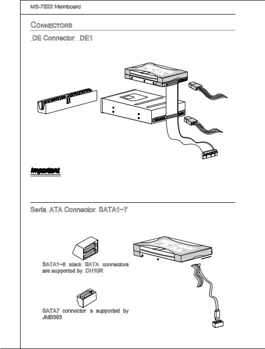
SATA
■6 SATA ports (SATA1~6) by ICH10R
■1 SATA port (SATA7) by JMicron® JMB363
■1 E-SATA port by JMicron® JMB363
■Supports storage and data transfers at up to 3 Gb/s
RAID
■SATA1~6 support Intel Martix Storage Technology (AHCI + RAID 0/1/5/10) by ICH10R
1394
■ 2 1394 ports (rear*1, front*1) by by JMicron® JMB381
Connectors
■Back panel
-1 PS/2 mouse port
-1 PS/2 keyboard port
En-2
-1 Optical S/PDIF-Out port
-1 1394 port
-1 eSATA port
-6 USB 2.0 Ports
-1 LAN jack
-6 flexible audio jacks
■On-Board Connectors
-3 USB 2.0 connectors
-1 1394 connector
-1 chassis intrusion connector
-1 serial port connector
-1 TPM Module connector
-1 CD-In connector
-1 front audio connector
-1 Clear CMOS button
-1 Power button
-1 Reset button
TPM
 (optional)
■ - Supports TPM
Slots
■2 PCI Express gen2 x16 slots (PCI_E2, PCI_E4)
■1 PCI Express x16 slot supports up to PCI Express gen2 x4 speed (PCI_E5)
■2 PCI Express gen1 x1 slots
■2 PCI slots, support 3.3V/ 5V PCI bus Interface
Form
 Factor

■ ATX (30.5cm X 24.4cm)
Mounting
■9 mounting holes
(If you need to purchase accessories and request the part numbers, you could search the product web page and find details on our web address below http://www.msi.com/index.php)
En-3
MS-7522 Mainboard
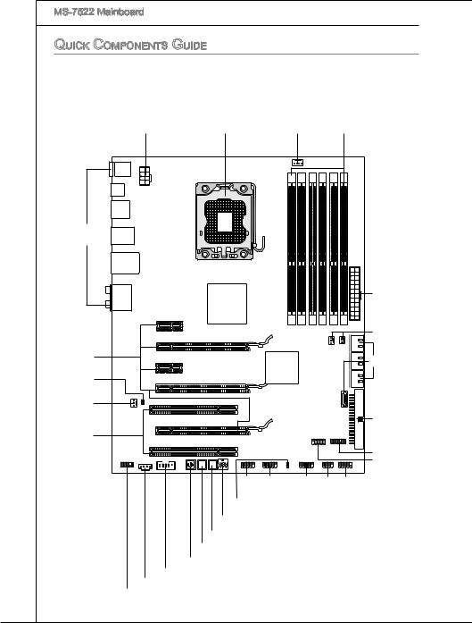
Quick Components Guide
|
JPWR2, En-13 |
CPU, En-5 |
CPUFAN1, En-17 DDR3, En-9 |
||
|
|
|
|
|
|
|
|
|
|
|
|
|
|
|
|
|
|
|
|
|
|
|
|
|
|
|
|
|
|
|
|
|
|
|
|
BackPanel, |
|
En-11 |
|
|
JPWR1, En-13 |
|
SYSFAN1,3, En-17 |
PCIE Slot, En-24 |
SATA1~7, En-16 |
|
|
JSP1, En-21 |
|
SYSFAN2, En-17 |
|
|
|
|
IDE1, En-16 |
PCI Slot, En-26 |
|
|
|
|
JTPM1, En-20 |
RESET |
Clr |
JCOM1, En-20 |
CMOS |
|
|
|
|
JUSB1~3, |
|
En-19 |
|
|
|
|
|
|
JFP1, |
|
JFP2, En-17 |
||||
JCI1,En-18
CPU_CLK1, En-22
CLR_CMOS1, En-23
RESET1, En-23
POWER1, En-23
J1394_1, En-18
JCD1, En-18
JAUD1, En-19
En-4
CPU (Central

 Processing Unit
 )
)
When you are installing the CPU, make sure to install the cooler to prevent overheating. If you do not have the CPU cooler, consult your dealer before turning on the computer.
For the latest information about CPU, please visit http://www.msi.com/index.php?func=cpuform2
Important
Overheating
Overheating will seriously damage the CPU and system. Always make sure the cooling fan can work properly to protect the CPU from overheating. Make sure that you apply an even layer of thermal paste (or thermal tape) between the CPU and the heatsink to enhance heat dissipation.
Replacing the CPU
While replacing the CPU, always turn off the ATX power supply or unplug the power supply’s power cord from the grounded outlet first to ensure the safety of CPU.
Overclocking
This mainboard is designed to support overclocking. However, please make sure your components are able to tolerate such abnormal setting, while doing overclocking. Any attempt to operate beyond product specifications is not recommended. We do not guarantee the damages or risks caused by inadequate operation or beyond product specifications.
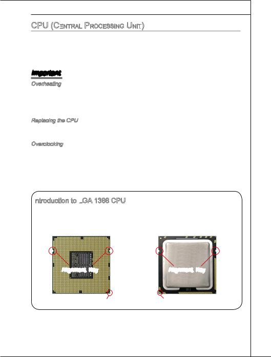
Introduction to LGA
 1366 CPU
The pin-pad side of LGA 1366 CPU.
The surface of LGA 1366 CPU. Remember to apply some thermal paste on it for better heat dispersion.
Alignment Key |
Alignment Key |
Yellow triangle is the Pin 1 indicator |
Yellow triangle is the Pin 1 indicator |
En-5

MS-7522 Mainboard
CPU & Cooler Installation
When you are installing the CPU, make sure the CPU has a cooler attached on the top to prevent overheating. Meanwhile, do not forget to apply some thermal paste on CPU before installing the heat sink/cooler fan for better heat dispersion.
Follow the steps below to install the CPU & cooler correctly. Wrong installation will cause the damage of your CPU & mainboard.
1. Open the load level.
2.Lift the load lever up and open the load plate.
3.The CPU socket has a plastic cap on it to protect the contact from damage. Before you install CPU, always cover it to protect the socket pin. Romove the cap from the lever hinge side (as the arrow shows).
4.After confirming the CPU direction for correct mating, put down the CPU in the socket housing frame. Be sure to grasp on the edge of the CPU base. Note that the alignment keys are matched.
Alignment Key
En-6
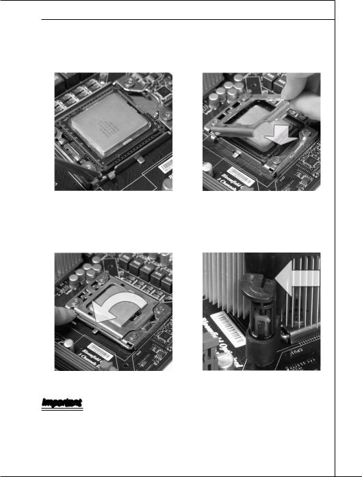
5.Visually inspect if the CPU is seated well into the socket. If not, take out the CPU with pure vertical motion and reinstall.
7.Press down the load lever lightly onto the load plate, and then secure the lever with the hook under retention tab.
6.Cover the load plate onto the package.
8.Make sure the four hooks are in porper position before you install the cooler.
Important
•Confirm if your CPU cooler is firmly installed before turning on your system.
•Do not touch the CPU socket pins to avoid damaging.
En-7
MS-7522 Mainboard
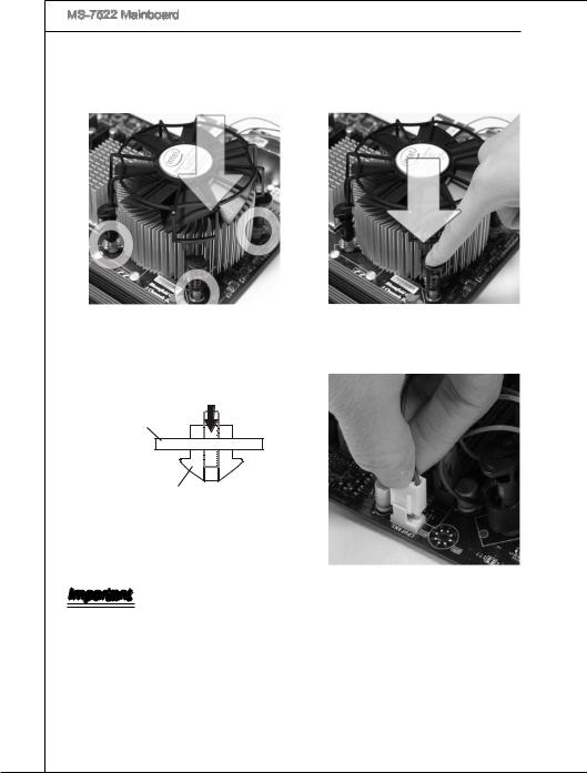
9.Aligntheholesonthemainboardwith the heatsink. Push down the cooler until its four clips get wedged into the holes of the mainboard.
11.Turn over the mainboard to confirm that the clip-ends are correctly inserted.
10.Press the four hooks down to fasten the cooler.
12.Finally, attach the CPU Fan cable to the CPU fan connector on the mainboard.
Mainboard
Hook
Important
•Read the CPU status in BIOS.
•Whenever CPU is not installed, always protect your CPU socket pin with the plastic cap covered to avoid damaging.
• Mainboard photos shown in this section are for demonstration of the CPU/ cooler installation only. The appearance of your mainboard may vary depending on the model you purchase.
•Please refer to the documentation in the CPU fan package for more details about the CPU fan installation.
En-8
Memory

These DIMM slots are used for installing memory modules.
For more information on compatible components, please visit
http://www.msi.com/index.php?func=testreport
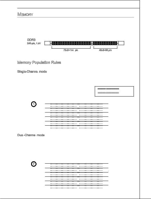
DDR3
240-pin, 1.5V
72x2=144 pin |
48x2=96 pin |
Memory Population Rules
Please refer to the following illustrations for memory population rules. Single-Channel
 mode
mode
When you have only one memory module, please always insert it into the DIMM_A0 first (as way 1 shown in below).


 Installed
 Empty
Empty
1

 DIMM_A1


 DIMM_A0


 DIMM_B1


 DIMM_B0


 DIMM_C1


 DIMM_C0
Dual -Channel
 mode
mode
In Dual-Channel mode, the memory modules can transmit and receive data with two data bus lines simultaneously. Enabling Dual-Channel mode can enhance the system performance. When you have two memory modules, please always insert them into the DIMM_A0 & DIMM_B0 (as way 2 shown in below).
2

 DIMM_A1


 DIMM_A0


 DIMM_B1


 DIMM_B0


 DIMM_C1


 DIMM_C0
En-9
MS-7522 Mainboard
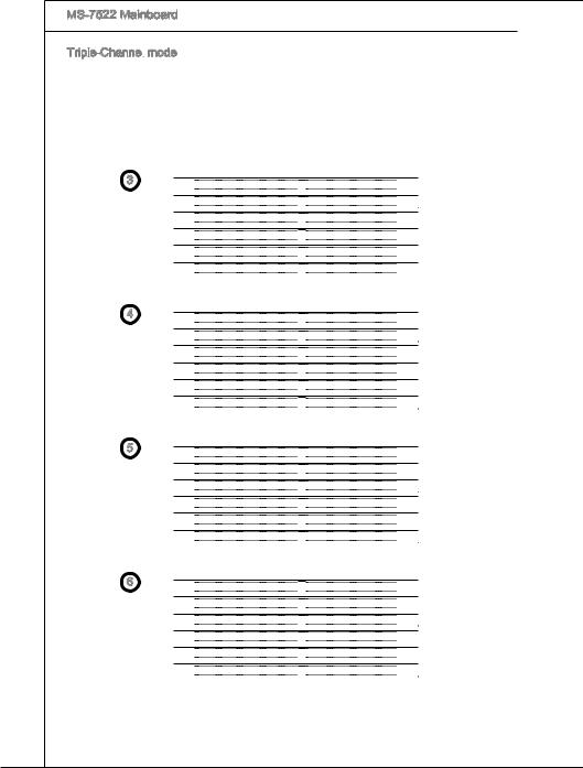
Triple-Channel
 mode
mode
In Triple-Channel mode, the memory modules can transmit and receive data with three data bus lines simultaneously. Enabling Three-Channel mode can enhance the best system performance. When you have three or more memory modules, please always insert them as the way 3/ 4/ 5/ 6 (shown in below) to get the best system performance.
3


 DIMM_A1


 DIMM_A0


 DIMM_B1


 DIMM_B0


 DIMM_C1


 DIMM_C0
4


 DIMM_A1


 DIMM_A0


 DIMM_B1


 DIMM_B0


 DIMM_C1


 DIMM_C0
5


 DIMM_A1


 DIMM_A0


 DIMM_B1


 DIMM_B0


 DIMM_C1


 DIMM_C0
6


 DIMM_A1


 DIMM_A0


 DIMM_B1


 DIMM_B0


 DIMM_C1


 DIMM_C0
En-10
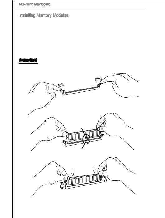
 Memory Modules
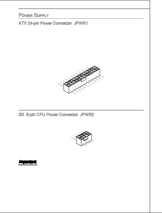
 JPWR1
JPWR1
 8-pin CPU Power Connector:
 JPWR2
JPWR2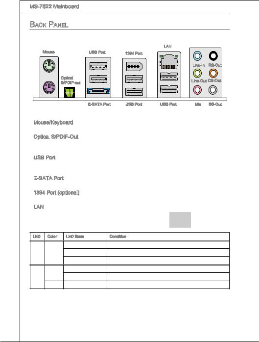
 S/PDIF
 -Out
-Out

 -SATA Port


 Connector:
 IDE1
IDE1


 ATA Connector:
 SATA1~7
 are supported by ICH10R
 supported by
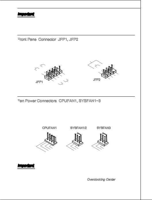
 Panel
Panel Connector:
 JFP1, JFP2
 Power Connectors:
 CPUFAN1, SYSFAN1~3
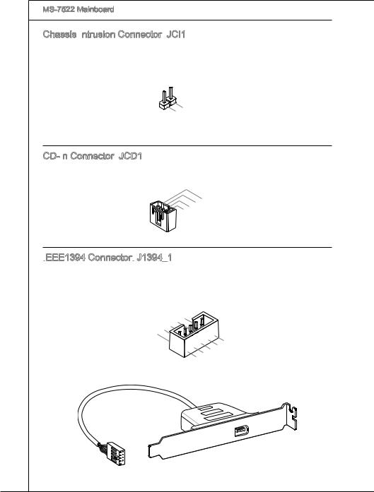
 Connector:
 JCI1
JCI1 Connector:
 JCD1
JCD1 Connector:
 J1394_1
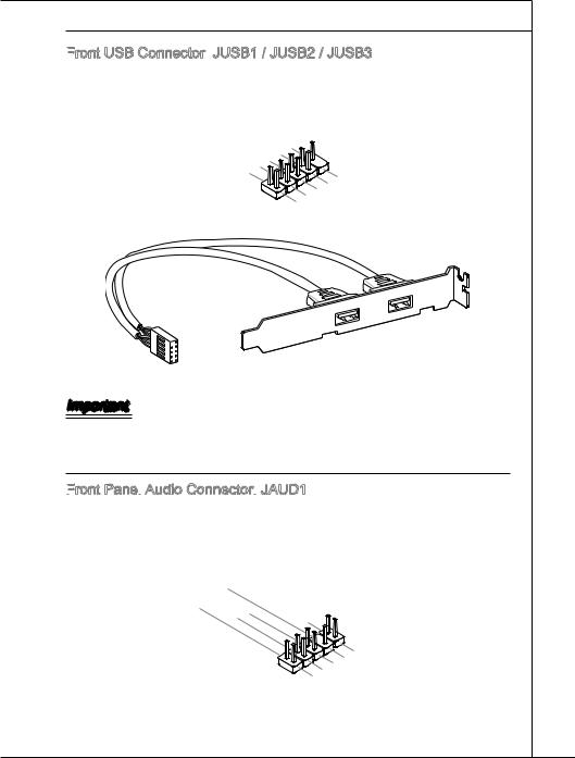
 USB Connector:
 JUSB1 / JUSB2 / JUSB3
 Panel
Panel
 Audio Connector:
 JAUD1
JAUD1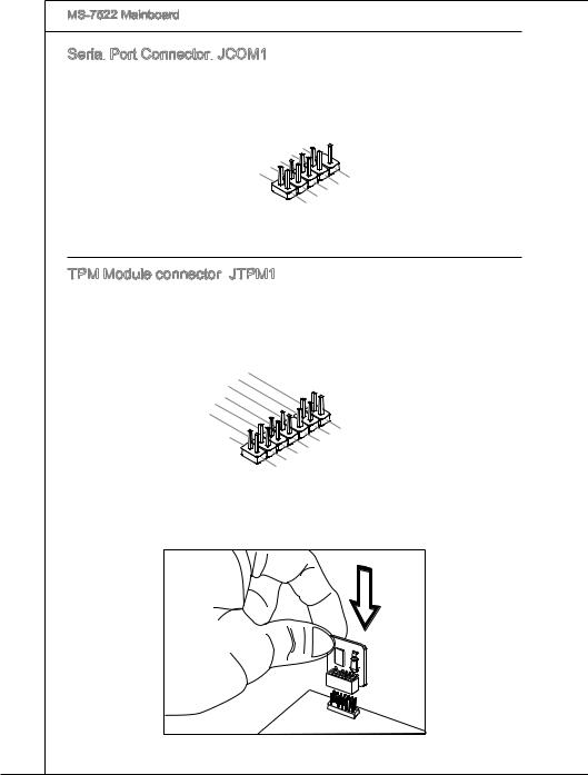

 Port Connector:
 JCOM1
JCOM1 JTPM1
JTPM1 Loading...