


 Loading...
Unpacking
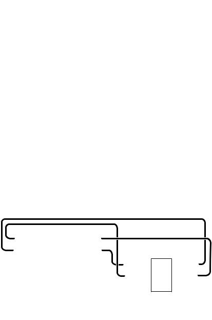
Thank you for buying the MSI® X470 GAMING PLUS motherboard. Check to make sure your motherboard box contains the following items. If something is missing, contact your dealer as soon as possible.
|
|
|
|
|
|
|
|
|
|
|
|
|
|
|
|
|
|
|
|
Motherboard User |
|
|
|
|
|
|
|
|
|
|
|
|
|
|
|
|
|
|
|
|
|
|
|
|
|
|
|
|
|
|
|
|
|
|
|
|
|
|
|
|
|
|
|
|
|
|
|
|
|
|
|
|
|
|
|
|
|
|
|
|
|
|
|
|
|
|
|
|
|
|
|
|
|
|
|
|
|
|
|
|
|
|
|
|
|
|
|
|
|
|
|
|
|
|
|
|
|
|
|
|
|
|
|
|
|
|
|
|
|
|
|
|
|
|
|
|
|
|
|
|
|
|
|
|
|
|
|
|
|
|
|
|
|
|
|
|
|
|
|
|
|
|
|
|
|
|
|
|
|
|
|
|
|
|
|
|
|
|
|
|
|
|
|
|
|
|
|
|
|
|
|
|
|
|
|
|
|
|
|
|
|
|
|
|
|
|
|
|
|
|
|
|
|
|
|
|
|
|
|
|
|
|
|
|
|
|
|
|
|
|
|
|
|
|
|
|
|
|
|
|
|
|
|
|
|
|
|
|
Drivers & Utilities |
||
|
|
|
|
|
|
|
|
|
|
|
|
|
|
|
|
|
|
|||
|
|
|
|
|
|
|
|
|
|
|
|
|
|
|
|
|
|
|||
|
|
|
|
|
|
|
|
|
|
|
|
|
|
|
|
|
|
Disc |
Guide |
|
|
|
|
|
|
|
|
|
|
|
|
|
|
|
|
|
|
|
|||
|
|
|
|
|
|
|
|
|
|
|
|
|
|
|
|
|
|
|||
|
|
|
|
|
|
|
|
|
|
|
|
|
|
|
|
|
|
|
||
Motherboard
I/O Shield |
M.2 Screw x2 |
|
|
|
SATA Cable x2 |
Case Badge |
SATA Cable Labels |
|
Unpacking 1
Safety Information
yThe components included in this package are prone to damage from electrostatic discharge (ESD). Please adhere to the following instructions to ensure successful computer assembly.
yEnsure that all components are securely connected. Loose connections may cause the computer to not recognize a component or fail to start.
yHold the motherboard by the edges to avoid touching sensitive components.
yIt is recommended to wear an electrostatic discharge (ESD) wrist strap when handling the motherboard to prevent electrostatic damage. If an ESD wrist strap is not available, discharge yourself of static electricity by touching another metal object before handling the motherboard.
yStore the motherboard in an electrostatic shielding container or on an anti-static pad whenever the motherboard is not installed.
yBefore turning on the computer, ensure that there are no loose screws or metal components on the motherboard or anywhere within the computer case.
yDo not boot the computer before installation is completed. This could cause permanent damage to the components as well as injury to the user.
yIf you need help during any installation step, please consult a certified computer technician.
yAlways turn off the power supply and unplug the power cord from the power outlet before installing or removing any computer component.
yKeep this user guide for future reference.
yKeep this motherboard away from humidity.
yMake sure that your electrical outlet provides the same voltage as is indicated on the PSU, before connecting the PSU to the electrical outlet.
yPlace the power cord such a way that people can not step on it. Do not place anything over the power cord.
yAll cautions and warnings on the motherboard should be noted.
yIf any of the following situations arises, get the motherboard checked by service personnel:
Liquid has penetrated into the computer.
The motherboard has been exposed to moisture.
The motherboard does not work well or you can not get it work according to user guide.
The motherboard has been dropped and damaged.
The motherboard has obvious sign of breakage.
yDo not leave this motherboard in an environment above 60°C (140°F), it may damage the motherboard.
2 Safety Information
Quick Start
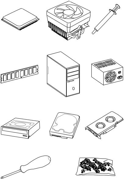
Preparing Tools and Components
AMD® AM4 CPU
Thermal Paste
CPU Fan
DDR4 Memory
Power Supply Unit
Chassis
SATA DVD Drive |
SATA Hard Disk Drive |
Graphics Card |
Phillips Screwdriver |
A Package of Screws |
Quick Start 3

Installing a Processor
https://youtu.be/Xv89nhFk1vc
1 
3
2 

5
 4
4
6 |
8 |
9 |
|
|
|
|
7 |
CPU_FAN1 |
|
|
4 Quick Start
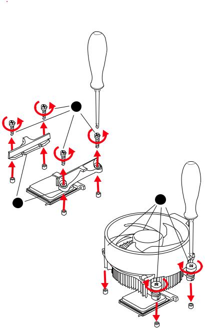
 Important
If you are installing the screw-type CPU heatsink, please follow the figure below to remove the retention module first and then install the heatsink.
1
2 |
3 |
|
Quick Start 5
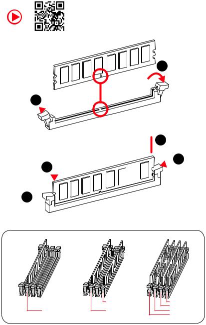
Installing DDR4 memory
http://youtu.be/T03aDrJPyQs
1
1 
2
 3 2
3 2 


3 


|
DIMMB2 |
DIMMB2 |
|
|
DIMMB1 |
DIMMA2 |
DIMMA2 |
DIMMA2 |
|
|
DIMMA1 |
6 Quick Start
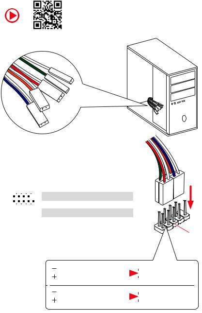
Connecting the Front Panel Header
http://youtu.be/DPELIdVNZUI
|
|
- |
|
|
|
LED |
|
|
LED+ |
POWER |
|
|
POWER |
||
|
LED |
|
|
SW |
HDD |
||
|
|
||
POWER |
|
|
|
SW |
|
|
|
RESET |
|
|
|
2 |
|
|
|
10 |
|
1 |
HDD LED + |
2 |
Power LED + |
|
|
|
|
|
|
|
|
|
|||
|
|
|
3 |
HDD LED - |
4 |
Power LED - |
||||
|
|
|
|
|
|
|
||||
|
|
|
|
|
|
|
|
|
|
|
|
|
|
|
|
|
|
5 |
Reset Switch |
6 |
Power Switch |
1 |
|
|
|
9 |
|
|||||
|
|
|
|
|
|
|
|
|||
|
|
JFP1 |
|
|
7 |
Reset Switch |
8 |
Power Switch |
||
|
|
|
|
|
|
|
|
|||
|
|
|
|
9 |
Reserved |
10 |
No Pin |
|||
|
|
|
|
|
|
|
||||
|
|
|
|
|
|
|
|
|
|
|
RESETSW
HDDLED
|
HDD LED |
|
|
|
|
|
HDD LED - |
|
|
|
|
|
|
||
|
|
|
|
|
|
|
HDD LED + |
|
|
|
|
|
|
|
|
|
|
|
|
|
|
|
POWER LED - |
|
|
|
|
|
|
|
|
|
POWER LED |
|
|
|
|
|
POWER LED + |
|
|
|
|
|
|
|
Quick Start 7
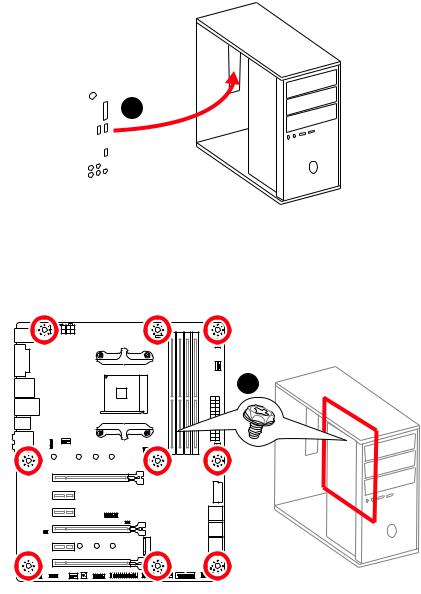
Installing the Motherboard
1
2
8 Quick Start
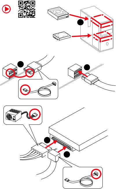
Installing SATA Drives
http://youtu.be/RZsMpqxythc |
1 |
|
2 |
3 |
|
5
 4
4
Quick Start 9
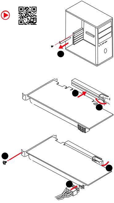
Installing a Graphics Card
http://youtu.be/mG0GZpr9w_A
1
3
2 
5
 4
4
6 

10 Quick Start
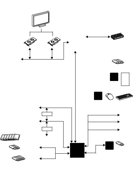
Connecting Peripheral Devices
A |
|
|
|
|
- |
|
|
|
|
Ryzen™ |
Desktop |
|
|
|
|
|
|
||
Series/Athlon™ |
|
Processors |
|
|
|
|
Processors with |
|
|
|
|
|
Radeon |
|
|
|
|
Vega |
Graphics |
|
|
|
|
|
|
|
|
|
& |
Quick Start 11
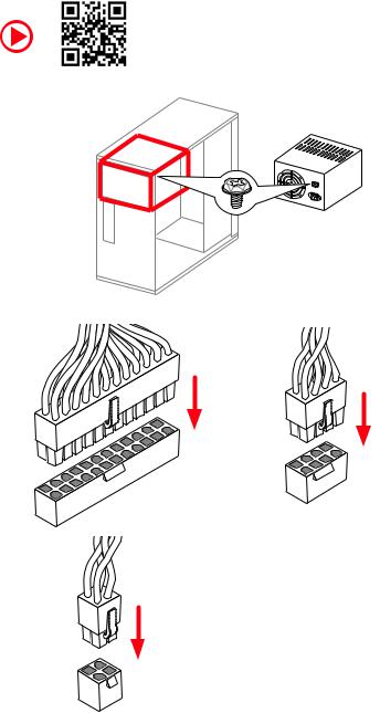
Connecting the Power Connectors
http://youtu.be/gkDYyR_83I4
ATX_PWR1 |
CPU_PWR1 |
|
CPU_PWR2
12 Quick Start
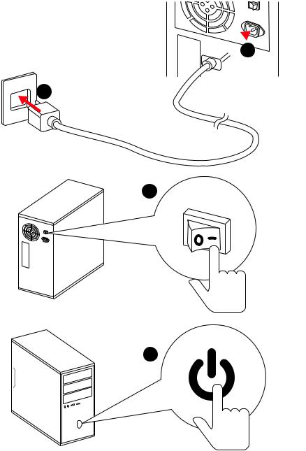
Power On
 1
1
2
3
4
Quick Start 13
Contents |
|
Unpacking.............................................................................................................. |
1 |
Safety Information................................................................................................. |
2 |
Quick Start ............................................................................................................. |
3 |
Preparing Tools and Components.......................................................................... |
3 |
Installing a Processor............................................................................................. |
4 |
Installing DDR4 memory ........................................................................................ |
6 |
Connecting the Front Panel Header....................................................................... |
7 |
Installing the Motherboard..................................................................................... |
8 |
Installing SATA Drives............................................................................................. |
9 |
Installing a Graphics Card .................................................................................... |
10 |
Connecting Peripheral Devices ............................................................................ |
11 |
Connecting the Power Connectors....................................................................... |
12 |
Power On............................................................................................................... |
13 |
Specifications....................................................................................................... |
17 |
Block Diagram .................................................................................................... |
22 |
Rear I/O Panel ..................................................................................................... |
23 |
LAN Port LED Status Table................................................................................... |
23 |
Audio Ports Configuration .................................................................................... |
23 |
Realtek HD Audio Manager .................................................................................. |
24 |
Overview of Components .................................................................................... |
26 |
CPU Socket ........................................................................................................... |
28 |
DIMM Slots............................................................................................................ |
29 |
PCI_E1~6: PCIe Expansion Slots.......................................................................... |
30 |
M2_1~2: M.2 Slots (Key M) ................................................................................... |
32 |
SATA1~6: SATA 6Gb/s Connectors ....................................................................... |
33 |
JLPT1: Parallel Port Connector ........................................................................... |
33 |
CPU_PWR1, CPU_PWR2, ATX_PWR1: Power Connectors .................................. |
34 |
JUSB1~2: USB 2.0 Connectors............................................................................. |
35 |
JUSB3~4: USB 3.1 Gen1 Connectors ................................................................... |
35 |
CPU_FAN1, PUMP_FAN1, SYS_FAN1~4: Fan Connectors................................... |
36 |
JAUD1: Front Audio Connector ............................................................................ |
37 |
JCI1: Chassis Intrusion Connector....................................................................... |
37 |
JFP1, JFP2: Front Panel Connectors ................................................................... |
38 |
JTPM1: TPM Module Connector........................................................................... |
38 |
JCOM1: Serial Port Connector ............................................................................. |
39 |
JRGB1, JRGB2: RGB LED Connectors ................................................................. |
39 |
JBAT1: Clear CMOS (Reset BIOS) Jumper ........................................................... |
40 |
14 Contents
CLR_CMOS1: Clear CMOS Button........................................................................ |
40 |
BIOS Setup........................................................................................................... |
41 |
Entering BIOS Setup............................................................................................. |
41 |
Resetting BIOS...................................................................................................... |
42 |
Updating BIOS....................................................................................................... |
42 |
EZ Mode ................................................................................................................ |
43 |
Advanced Mode .................................................................................................... |
45 |
SETTINGS.............................................................................................................. |
46 |
Advanced............................................................................................................... |
46 |
Boot....................................................................................................................... |
51 |
Security................................................................................................................. |
52 |
Save & Exit............................................................................................................ |
54 |
OC.......................................................................................................................... |
55 |
M-FLASH .............................................................................................................. |
60 |
OC PROFILE.......................................................................................................... |
61 |
HARDWARE MONITOR.......................................................................................... |
62 |
A-XMP Operation .................................................................................................. |
63 |
Software Description........................................................................................... |
64 |
Installing Windows® 10......................................................................................... |
64 |
Installing Drivers .................................................................................................. |
64 |
Installing Utilities ................................................................................................. |
64 |
APP MANAGER ..................................................................................................... |
65 |
LIVE UPDATE 6...................................................................................................... |
66 |
COMMAND CENTER ............................................................................................. |
68 |
GAMING APP......................................................................................................... |
72 |
X-BOOST ............................................................................................................... |
77 |
MYSTIC LIGHT....................................................................................................... |
79 |
MYSTIC LIGHT PARTY ........................................................................................... |
83 |
Joining Group........................................................................................................ |
84 |
Group Control Panel ............................................................................................. |
85 |
Inviting Member.................................................................................................... |
86 |
SMART TOOL......................................................................................................... |
87 |
RAMDISK............................................................................................................... |
89 |
Nahimic 2.5........................................................................................................... |
90 |
RAID Configuration.............................................................................................. |
95 |
Using AMD RAID Controller BIOS Configuration Utility....................................... |
95 |
Initialize Disks ...................................................................................................... |
97 |
Create Arrays........................................................................................................ |
98 |
Delete Arrays ........................................................................................................ |
99 |
Swap Arrays........................................................................................................ |
100 |
Contents 15
Manage Spares ................................................................................................... |
101 |
Change the Controller Options........................................................................... |
102 |
Booting the system from an array...................................................................... |
102 |
Pausing the boot sequence for warning messages ........................................... |
102 |
Change the Staggered Spinup Count ................................................................. |
103 |
Using UEFI to create a 2.2TB RAID .................................................................... |
104 |
Installing RAID Driver......................................................................................... |
105 |
Troubleshooting ................................................................................................ |
106 |
16 Contents

Specifications
CPU |
Supports AMD® Ryzen™ Desktop Processors and AMD® |
|
A-Series/Athlon™ Processors for Socket AM4 |
||
|
||
|
|
|
Chipset |
AMD® X470 Chipset |
|
|
|
|
|
y4x DDR4 memory slots, support up to 64GB |
|
|
Supports DDR4 1866/ 2133/ 2400/ 2667 Mhz by JEDEC, |
|
|
and 2667/ 2800/ 2933/ 3000/ 3066/ 3200/ 3466 Mhz by |
|
|
A-XMP OC MODE* |
|
Memory |
yDual channel memory architecture |
|
ySupports non-ECC UDIMM memory |
||
|
||
|
ySupports ECC UDIMM memory |
|
|
* A-series/ Athlon™ processors support up to 2400 MHz. And the supporting |
|
|
frequency of memory varies with installed processor. Please refer www.msi.com |
|
|
for more information on compatible memory. |
|
|
|
|
|
y2x PCIe 3.0 x16 slots (PCIE_1, PCIE_4) |
|
|
Ryzen™ Desktop Processors support x16/x0, x8/x8 |
|
|
mode |
|
|
Ryzen™ Desktop Processors with Radeon Vega |
|
Expansion Slots |
Graphics and A-Series/Athlon™ Processors support x8/ |
|
|
x0 mode |
|
|
y1x PCIe 2.0 x16 slot (PCIE_6, supports x4 mode)* |
|
|
y3x PCIe 2.0 x1 slots |
|
|
* PCI_E6 slot will be unavailable when installing M.2 PCIe SSD in M2_2 slot. |
|
|
|
|
|
y1x DVI-D port, supports a maximum resolution of |
|
|
1920x1200@60Hz* |
|
Onboard Graphics |
y1x HDMI™ port 1.4, supports a maximum resolution of |
|
4096x2160@30Hz* |
||
|
* Only support when using Ryzen™ Desktop Processors with Radeon Vega |
|
|
Graphics and A-Series/Athlon™ Processors |
|
|
* Maximum shared memory of 2048 MB |
|
|
|
|
|
yRyzen™ Desktop Processors |
|
|
Supports 3-Way AMD® CrossFire™ Technology |
|
Multi-GPU |
yRyzen™ Desktop Processors with Radeon Vega Graphics |
|
|
and A-Series/Athlon™ Processors |
|
|
Supports 2-Way AMD® CrossFire™ Technology |
|
LAN |
1x Realtek® 8111H Gigabit LAN controller |
|
|
|
|
|
Continued on next page |
Specifications 17

Continued from previous page
|
y6x SATA 6Gb/s ports (from AMD® X470 Chipset) |
|
|
y2x M.2 ports (Key M)* |
|
|
M2_1 slot (from AMD® processor) supports PCIe 3.0 x4 |
|
|
(Ryzen™ Desktop Processors ) or PCIe 3.0 x2 (A-series/ |
|
Storage |
Athlon™ Processors) 2242/ 2260 /2280/ 22110 storage |
|
devices |
||
|
||
|
M2_2 slot (from AMD® X470 Chipset) supports PCIe 2.0 |
|
|
x4 and SATA 6Gb/s 2242/ 2260 /2280 storage devices |
|
|
* SATA1 port will be unavailable when installing SATA M.2 SSD in M2_2 slot. |
|
|
* PCI_E6 slot will be unavailable when installing PCIe M.2 SSD in M2_2 slot. |
|
|
|
|
|
AMD® X470 Chipset |
|
RAID |
ySupports RAID 0, RAID 1 and RAID 10 for SATA storage |
|
|
devices |
|
|
|
|
|
yASMedia® ASM1143 Chipset |
|
|
2x USB 3.1 Gen2 (SuperSpeed USB 10Gbps) Type-A |
|
|
ports on the back panel |
|
|
yAMD® X470 Chipset |
|
|
4x USB 3.1 Gen1 (SuperSpeed USB) ports through the |
|
USB |
internal USB connectors |
|
6x USB 2.0 (High-speed USB) ports (2 Type-A ports on |
||
|
||
|
the back panel, 4 ports available through the internal |
|
|
USB connectors) |
|
|
yAMD® CPU |
|
|
4x USB 3.1 Gen1 (SuperSpeed USB) Type-A ports on the |
|
|
back panel |
|
|
|
|
|
yRealtek® ALC892 Codec |
|
Audio |
y7.1-Channel High Definition Audio |
|
|
ySupports S/PDIF output |
|
|
|
|
|
Continued on next page |
18 Specifications

Continued from previous page
|
y1x PS/2 keyboard/ mouse combo port |
|
|
y2x USB 2.0 Type-A ports |
|
|
y1x DVI-D port |
|
Back Panel |
y1x HDMI™ 1.4 port |
|
y4x USB 3.1 Gen1 Type-A ports |
||
Connectors |
||
y1x LAN (RJ45) port |
||
|
||
|
y2x USB 3.1 Gen2 Type-A ports |
|
|
y5x OFC audio jacks |
|
|
y1x Optical S/PDIF OUT connector |
|
|
|
|
|
y1x 24-pin ATX main power connector |
|
|
y1x 8-pin ATX 12V power connector |
|
|
y1x 4-pin ATX 12V power connector |
|
|
y6x SATA 6Gb/s connectors |
|
|
y2x USB 2.0 connectors (support additional 4 USB 2.0 ports) |
|
|
y2x USB 3.1 Gen1 connectors (support additional 4 USB 3.1 |
|
|
Gen1 ports) |
|
|
y1x 4-pin CPU fan connector |
|
|
y1x 4-pin PUMP fan connector (supports up to 2A) |
Internal Connectors y4x 4-pin system fan connectors
y1x Serial port connector
y1x Parallel port connector
y2x 5050 RGB LED strip 12V connectors
y1x TPM module connector
y1x Front panel audio connector
y2x System panel connectors
y1x Chassis Intrusion connector
y1x Clear CMOS jumper
y1x Clear CMOS button
I/O Controller |
NUVOTON NCT6795D Controller Chip |
Continued on next page
Specifications 19

|
Continued from previous page |
|
|
|
|
|
yCPU/System temperature detection |
|
Hardware Monitor |
yCPU/System fan speed detection |
|
|
yCPU/System fan speed control |
|
|
|
|
Form Factor |
yATX Form Factor |
|
y12 in. x 9.6 in. (30.5 cm x 24.4 cm) |
||
|
||
|
|
|
|
y1x 128 Mb flash |
|
BIOS Features |
yUEFI AMI BIOS |
|
yACPI 6.1, SM BIOS 2.8 |
||
|
||
|
yMulti-language |
|
|
|
|
|
yDrivers |
|
|
yAPP MANAGER |
|
|
yCOMMAND CENTER |
|
|
yLIVE UPDATE 6 |
|
|
yMYSTIC LIGHT |
|
|
ySUPER CHARGER |
|
|
yGAMING APP |
|
Software |
yRAMDISK |
|
|
yX-BOOST |
|
|
ySMART TOOL |
|
|
yNahimic Audio |
|
|
yOpen Broadcaster Software (OBS) |
|
|
yNorton™ Internet Security Solution |
|
|
yGoogle Chrome™, Google Toolbar, Google Drive |
|
|
yCPU-Z MSI GAMING |
|
|
|
|
|
Continued on next page |
20 Specifications
Continued from previous page
|
yAudio |
|
|
Audio Boost |
|
|
Voice Boost |
|
|
Nahimic 2.5 |
|
|
yStorage |
|
|
Turbo M.2 |
|
|
yFan |
|
|
Pump Fan |
|
|
Smart Fan Control |
|
|
yLED |
|
|
Mystic Light |
|
|
Mystic Light Extension |
|
|
Mystic light SYNC |
|
|
EZ DEBUG LED |
|
|
yProtection |
|
Special Features |
PCI-E Steel Armor |
|
yPerformance |
||
|
||
|
Multi GPU-CrossFire Technology |
|
|
DDR4 Boost |
|
|
GAME Boost |
|
|
X-Boost |
|
|
A-XMP |
|
|
yStability |
|
|
7000+ Quality Test |
|
|
yVR |
|
|
VR Ready |
|
|
yGamer Experience |
|
|
RAMDisk |
|
|
yBIOS |
|
|
Click BIOS 5 |
|
|
yCertification |
|
|
GAMING Certified |
|
|
|
Specifications 21
Block Diagram
HDMI DVI-D
2 Channel DDR4 Memory
|
CPU |
|
1 x M.2 |
PCI Express Bus |
|
PCIex4 |
4 x USB 3.1 Gen1 |
|
Realtek |
|
ALC892 |
|
Audio Jacks |
|
|
NV6795 |
|
|
|
|
Super I/O |
|
|
|
|
P/S2 Mouse / Keyboard |
||
PCIe x4 slot |
|
|
|
|
Switch |
|
|
x1 |
PCIe x1 slot |
|
|
|
|
|
1 x M.2 |
|
|
x1 |
PCIe x1 slot |
|
|
|
||
Switch |
PCI |
|
x1 |
PCIe x1 slot |
|
|
|
||
6 x SATA 6Gb/s |
BusExpress |
|
|
|
|
|
|
|
|
4 x USB 3.1 Gen1 |
X470 |
ASMEDIA |
2 x USB 3.1 Gen2 |
|
|
ASM1143 |
|||
|
|
|
|
|
6 x USB 2.0 |
|
|
|
|
|
|
RTL8111H |
|
|
22 Block Diagram
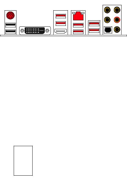
Rear I/O Panel
|
USB 3.1 Gen1 LAN |
Audio Ports |
|
PS/2 |
|
|
|
DVI-D |
USB 2.0 |
USB 3.1 Gen2 |
|
|
USB 3.1 Gen1 |
Optical S/PDIF-Out |
LAN Port LED Status Table
Link/ Activity LED
Status |
Description |
|
|
Off |
No link |
|
|
Yellow |
Linked |
|
|
Blinking |
Data activity |
|
|
Speed LED
Status |
Description |
|
|
Off |
10 Mbps connection |
|
|
Green |
100 Mbps connection |
|
|
Orange |
1 Gbps connection |
|
|
Audio Ports Configuration
Channel
Audio Ports
|
2 |
4 |
6 |
8 |
Center/ Subwoofer Out |
|
|
● |
● |
Rear Speaker Out |
|
● |
● |
● |
Line-In/ Side Speaker Out |
|
|
|
● |
Line-Out/ Front Speaker Out |
● |
● |
● |
● |
Mic In |
|
|
|
|
(●: connected, Blank: empty) |
|
|
|
|
Rear I/O Panel 23
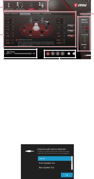
Realtek HD Audio Manager
After installing the Realtek HD Audio driver, the Realtek HD Audio Manager icon will appear in the system tray. Double click on the icon to launch.
Device
Selection
Advanced
Settings
 Jack Status
Application
Enhancement
Main Volume |
|
|
|
|
|
|
|
|
Connector |
|
|
|
|
|
|
|
|
||
|
|
|
|
|
|
||||
|
|
|
|
|
|
|
|
|
Settings |
|
|
|
|
|
|
Profiles |
|||
|
|
|
|
|
|
||||
yDevice Selection - allows you to select a audio output source to change the related options. The check sign indicates the devices as default.
yApplication Enhancement - the array of options will provide you a complete guidance of anticipated sound effect for both output and input device.
yMain Volume - controls the volume or balance the right/left side of the speakers that you plugged in front or rear panel by adjust the bar.
yProfiles - toggles between profiles.
yAdvanced Settings - provides the mechanism to deal with 2 independent audio streams.
yJack Status - depicts all render and capture devices currently connected with your computer.
yConnector Settings - configures the connection settings.
Auto popup dialog
When you plug into a device at an audio jack, a dialogue window will pop up asking you which device is current connected.
Each jack corresponds to its default setting as shown on the next page.
24 Rear I/O Panel
Audio jacks to headphone and microphone diagram
Audio jacks to stereo speakers diagram
AUDIO INPUT
Audio jacks to 7.1-channel speakers diagram
AUDIO INPUT
Rear |
Front |
Side |
Center/ |
|
Subwoofer |
Rear I/O Panel 25
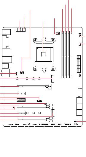
Overview of Components
JRGB2 M2_1
PCI_E1
PCI_E2
JTPM1 PCI_E3
JCI1 PCI_E4
JBAT1
PCI_E5
M2_2
PCI_E6
|
DIMMB1 |
|
|
DIMMA2 |
|
SYS_FAN1 |
DIMMA1 |
DIMMB2 |
|
|
|
CPU_PWR2 |
CPU_FAN1 |
|
CPU_PWR1 |
|
|
CPU Socket |
|
|
|
|
|
|
|
PUMP_FAN1 |
|
|
SYS_FAN3 |

 ATX_PWR1

 SYS_FAN4
 JUSB4
JUSB4
 SATA▼5▲6
 SATA▼3▲4
 SATA▼1▲2
JFP2
|
|
|
|
|
|
|
|
|
|
|
|
|
|
|
|
|
|
|
|
|
|
|
|
|
|
|
|
|
|
|
|
|
|
|
|
|
|
|
|
|
|
|
|
|
|
|
|
|
|
|
|
|
|
|
|
|
|
|
|
|
|
|
|
|
|
|
|
|
|
|
|
|
|
|
|
|
|
|
|
|
|
|
|
|
|
|
|||||||||||
JAUD1 |
|
|
|
|
|
|
|
|
|
|
|
|
|
|
|
|
|
|
|
|
|
|
|
|
|
|
|
|
|
|
|
|
|
|
|
|
|
|
|
|
|
|
|
|||||
|
|
|
|
|
|
|
|
|
|
|
|
|
|
|
|
|
|
|
|
|
|
|
|
|
|
|
|
|
|
|
|
|
|
|
|
|
|
|||||||||||
|
|
|
|
|
|
|
|
|
|
|
|
|
JCOM1 |
|
|
|
|
|
|
|
|
|
|
|
|
|
|
|
|
|
|
|
|
|
|
|
|
|||||||||||
|
|
|
|
JRGB1 |
|
|
|
|
|
|
|
|
|
|
|
|
|
|
|
|
|
|
|
|
|
|
|
|
|
|
|
|||||||||||||||||
|
|
|
|
|
|
|
|
|
|
|
|
|
|
|
|
|
|
|
|
JLPT1 |
|
|
|
|
|
|
|
|
|
|
|
|
|
JFP1 |
||||||||||||||
|
|
|
|
|
|
|
|
|
|
|
|
|
|
|
|
|
|
|
|
|
|
|
|
|
|
|
|
|
|
|
|
|
|
|
||||||||||||||
|
|
|
|
|
SYS_FAN2 |
|
|
|
|
|
|
|
|
|
|
|
|
|
|
|
|
|
JUSB3 |
|||||||||||||||||||||||||
|
|
|
|
|
|
|
|
|
|
|
|
|
|
|
|
|
|
|
|
|
|
|
|
|
|
|
|
|
|
|
|
|
|
|
|
|
|
|
|
|
|
|||||||
|
|
|
|
|
|
|
|
Clear CMOS |
|
|
|
|
|
JUSB2 |
||||||||||||||||||||||||||||||||||
|
|
|
|
|
|
|
|
|
|
|
|
|
|
|
|
|
|
|
|
|
|
|
|
|
|
|
|
|
|
|
|
|
|
|
|
|
|
|
|
|
|
|
|
|
|
|
|
|
|
|
|
|
|
|
|
|
|
|
|
|
|
|
|
|
|
|
|
|
|
|
|
|
|
|
|
|
|
|
|
JUSB1 |
|||||||||||||||||
26 Overview of Components
Component Contents
Port Name |
Port Type |
Page |
|
|
|
|
|
CLR_CMOS1 |
Clear CMOS Button |
40 |
|
|
|
|
|
CPU_FAN1, PUMP_FAN1, |
Fan Connectors |
36 |
|
SYS_FAN1~4 |
|||
|
|
||
|
|
|
|
CPU_PWR1, CPU_PWR2, |
Power Connectors |
34 |
|
ATX_PWR1 |
|||
|
|
||
|
|
|
|
CPU Socket |
AM4 CPU Socket |
28 |
|
|
|
|
|
DIMMA1, DIMMA2, |
DIMM Slots |
29 |
|
DIMMB1, DIMMB2 |
|||
|
|
||
|
|
|
|
JAUD1 |
Front Audio Connector |
37 |
|
|
|
|
|
JBAT1 |
Clear CMOS (Reset BIOS) Jumper |
40 |
|
|
|
|
|
JCI1 |
Chassis Intrusion Connector |
37 |
|
|
|
|
|
JCOM1 |
Serial Port Connector |
39 |
|
|
|
|
|
JFP1, JFP2 |
Front Panel Connectors |
38 |
|
|
|
|
|
JLPT1 |
Parallel Port Connector |
33 |
|
|
|
|
|
JRGB1, JRGB2 |
RGB LED Connectors |
39 |
|
|
|
|
|
JTPM1 |
TPM Module Connector |
38 |
|
|
|
|
|
JUSB1~2 |
USB 2.0 Connectors |
35 |
|
|
|
|
|
JUSB3~4 |
USB 3.1 Gen1 Connectors |
35 |
|
|
|
|
|
M2_1~2 |
M.2 Slots (Key M) |
32 |
|
|
|
|
|
PCI_E1~6 |
PCIe Expansion Slots |
30 |
|
|
|
|
|
SATA1~6 |
SATA 6Gb/s Connectors |
33 |
|
|
|
|
Overview of Components 27
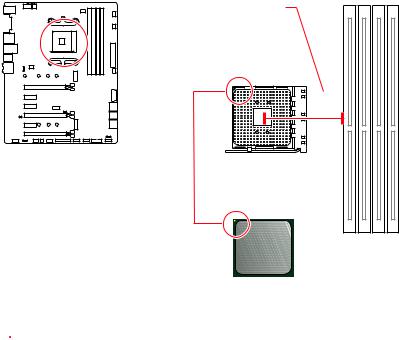
CPU Socket
Distance from the center of the
CPU to the nearest DIMM slot.
53.43 mm
Introduction to the AM4 CPU
The surface of the AM4 CPU has a yellow triangle to assist in correctly lining up the CPU for motherboard placement. The yellow triangle is the Pin 1 indicator.
 Important
yWhen changing the processor, the system configuration could be cleared and reset BIOS to default values, due to the AM4 processor’s architecture.
yAlways unplug the power cord from the power outlet before installing or removing the CPU.
yWhen installing a CPU, always remember to install a CPU heatsink. A CPU heatsink is necessary to prevent overheating and maintain system stability.
yConfirm that the CPU heatsink has formed a tight seal with the CPU before booting your system.
yOverheating can seriously damage the CPU and motherboard. Always make sure the cooling fans work properly to protect the CPU from overheating. Be sure to apply an even layer of thermal paste (or thermal tape) between the CPU and the heatsink to enhance heat dissipation.
yIf you purchased a separate CPU and heatsink/ cooler, Please refer to the documentation in the heatsink/ cooler package for more details about installation.
yThis motherboard is designed to support overclocking. Before attempting to overclock, please make sure that all other system components can tolerate overclocking. Any attempt to operate beyond product specifications is not recommended. MSI® does not guarantee the damages or risks caused by inadequate operation beyond product specifications.
28 Overview of Components
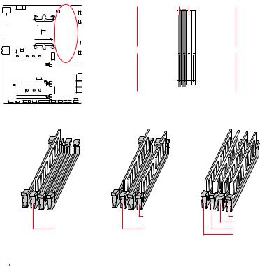
DIMM Slots
 DIMMA1
 DIMMB1
|
|
|
|
|
|
|
|
|
|
|
|
|
|
|
|
|
|
|
|
|
|
|
|
|
|
|
|
|
|
|
|
|
|
|
|
|
|
|
|
|
|
|
|
|
|
|
|
|
|
|
|
|
|
|
|
|
|
|
|
|
|
|
|
|
|
|
|
|
|
|
|
|
|
|
|
|
|
|
|
|
|
|
|
|
|
|
|
|
|
|
|
|
|
|
|
|
|
|
|
|
|
|
|
|
|
|
|
|
|
|
|
|
|
|
|
|
|
|
|
|
|
|
|
|
|
|
|
|
|
|
|
|
|
|
|
|
|
|
|
|
|
|
|
|
|
|
|
|
|
|
|
|
|
|
|
|
|
|
|
|
|
|
|
|
|
|
|
|
|
|
Channel A |
|
|
|
|
Channel B |
|||
|
|
|
|
|
|
|
|
|
|
|
|
|
|
|
|
|
|
|
|||||||||||
|
|
|
|
|
|
|
|
|
|
|
|
|
|
|
|
|
|
|
|
|
|
|
|
|
|
|
|
|
|
 DIMMA2
 DIMMB2
Memory module installation recommendation
|
DIMMB2 |
DIMMB2 |
|
|
DIMMB1 |
DIMMA2 |
DIMMA2 |
DIMMA2 |
|
|
DIMMA1 |
 Important
yAlways insert memory modules in the DIMMA2 slot first.
yDue to chipset resource usage, the available capacity of memory will be a little less than the amount of installed.
yBased on the processor specification, the Memory DIMM voltage below 1.35V is suggested to protect the processor.
ySome memory modules may operate at a lower frequency than the marked value when overclocking due to the memory frequency operates dependent on its Serial Presence Detect (SPD). Go to BIOS and find the DRAM Frequency to set the memory frequency if you want to operate the memory at the marked or at a higher frequency.
yIt is recommended to use a more efficient memory cooling system for full DIMMs installation or overclocking.
yThe stability and compatibility of installed memory module depend on installed CPU and devices when overclocking.
yDue to AM4 CPU/memory controller official specification limitation, the frequency of memory modules may operate lower than the marked value under the default state. Please refer www.msi.com for more information on compatible memory.
Overview of Components 29
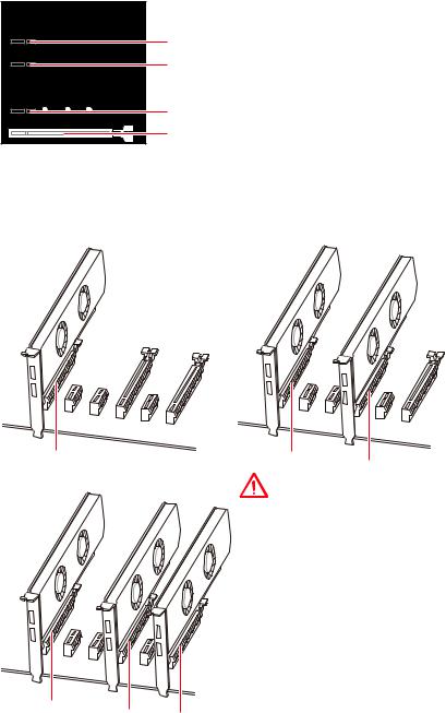
PCI_E1~6: PCIe Expansion Slots

 PCI_E1: PCIe 3.0 x16*/ PCIe 3.0 x8**
PCI_E2: PCIe 2.0 x1 PCI_E3: PCIe 2.0 x1

 PCI_E4: PCIe 3.0 x8*/ Unavailable**
PCI_E5: PCIe 2.0 x1 PCI_E6: PCIe 2.0 x4
*For Ryzen™ Desktop processors
**For Ryzen™ Desktop Processors with Radeon Vega Graphics & A-Series/Athlon™ Processors
Multiple graphics cards installation recommendation (Ryzen™ series processors)
x16 |
x8 |
x8 |
|
|
Important
yIf you install a large and heavy graphics card, you need to use a tool such as MSI Gaming Series Graphics Card Bolster to support its weight to prevent deformation of the slot.
yFor a single PCIe x16 expansion card installation with optimum performance, using the PCI_E1 slot is recommended.
x8
yWhen adding or removing expansion
cards, always turn off the power supply
and unplug the power supply power
cable from the power outlet. Read the expansion card’s documentation to
check for any necessary additional hardware or software changes.
x8 x4
30 Overview of Components
Loading...