


 Loading...
Table of Contents
FOREWORD from Steve Dunnington .................. |
5 |
THE BASICS |
|
How to use this Manual ....................................... |
6 |
Setup and Connections ........................................ |
6 |
Overview and Features ........................................ |
8 |
Signal Flow .................................................................... |
10 |
Basic Operation ......................................................... |
11 |
THE COMPONENTS |
|
A. Oscillator Section ............................................... |
12 |
B. Filter Section ......................................................... |
14 |
C. Envelope Generators Section .................... |
16 |
D. Modulation Section .......................................... |
18 |
E. Output Section .................................................... |
19 |
F. Input/Output Panel ............................................ |
20 |
G. Interface Panel ..................................................... |
21 |
THE USER INTERFACE |
|
Preset Mode ................................................................ |
23 |
Master Mode ............................................................... |
26 |
A. Menus .................................................... |
26 |
B. Advanced Presets ........................... |
36 |
C. System Exclusive ............................. |
42 |
D. System Utilities.................................. |
45 |
THE USER INTERFACE (con’t) |
|
Performance Sets ................................................................ |
50 |
Activating the Arpeggiator and Latch .................... |
52 |
How the SP handles MIDI ............................................. |
54 |
APPENDICES |
|
A – LFO Sync Modes ..................................................... |
58 |
B – Arpeggiator Clock Source .................................. |
59 |
C – The Calibration Preset ......................................... |
60 |
D – Accessories ................................................................. |
61 |
E – Tutorial ............................................................................. |
62 |
F – MIDI Implementation Chart .............................. |
67 |
G – Service & Support Information ........................ |
68 |
H – Caring for the Slim Phatty ................................... |
68 |
I – Using the CP-251 with the Slim Phatty ......... |
69 |
J – Specifications ................................................................. |
71 |
GLOSSARY ...................................................................................... |
72 |
SLIM PHATTY PRESET LIST ................................................ |
76 |
Page 3
SAFETY INFORMATION
*** Important Safety Instructions - Please Read ***
WARNING - When using electric products, basic precautions should always be followed, including the following:
1)Read all the instructions before using the product.
2)Do not use this product near water – for example, near a bathtub, washbowl, kitchen sink, in a wet basement, or near a swimming pool or the like.
3)This product should be used only with a car t or stand that is recommended by the manufacturer.
4)This product, in combination with an amplifier and headphones or speakers, may be capable of producing sound levels that could cause permanent hearing loss. Do not operate for a long period of time at a high volume level or at a level that is uncomfor table. If you experience any hearing loss or ringing in your ears, you should consult an audiologist.
5)The product should be located so that its location does not interfere with its proper ventilation.
6)The product should be located away from heat sources such as radiators, heat registers, or other products that produce heat.
7)The product should be connected to a power supply only of the type described in the operating instructions or as marked on the product.
8)The power supply cord of the product should be unplugged from the outlet when left unused for a long period of time.
9)Care should be taken so that objects do not fall upon and liquids are not spilled into the keyboard or front panel.
10) The product should be ser viced by qualified personnel when:
a)The power supply cord or the plug has been damaged
b)Objects have fallen, or liquid has been spilled onto the product
c)The product has been exposed to rain
d)The product does not appear to operate normally or exhibits a marked change in performance
e)The product has been dropped or the enclosure damaged.
11) Do not attempt to service the product beyond that described in the user-maintenance instructions.
All other ser vicing should be referred to qualified service personnel.
DANGER – INSTRUCTIONS PERTAINING TO RISK OF FIRE, ELECTRIC SHOCK, OR INJURY TO PERSONS:
Do not open the chassis. There are no user serviceable parts inside. Refer all servicing to qualified personnel only.
GROUNDING INSTRUCTIONS: This product must be grounded. If it should malfunction or breakdown, grounding provides a path of least resistance for electrical current to reduce the risk of electric shock. This product is equipped with a cord having an equipment grounding connector and a grounding plug. The plug must be plugged into an appropriate outlet that is properly installed and grounded in accordance with all local codes and ordinances.
DANGER – Improper connection of the equipment-grounding connector can result in a risk of electric shock. Check with a qualified electrician or serviceman if you are in doubt as to whether the product is properly grounded. Do not modify the plug provided with this product – if it will not fit in the outlet, have a proper outlet installed by a qualified electrician.

FOREWORD
Foreword
We here at Moog Music are grateful that you have chosen the Slim Phatty® analog synthesizer for your musical pursuits, and hope you find it to be an inspiring instrument for years to come.
Good things can come in small packages – and “the Slim” is no exception. Making the Slim Phatty has been a labor of love, transforming the electronic workings of the Little Phatty® into a package that is easily used as a desktop or a 3U rack-mount unit. Its small stature doesn’t take away from the massive sounds it can produce. This should come as no surprise as it is a direct descendant of the Little Phatty, Minimoog Voyager®, as well as the original Minimoog® Model D synthesizers. These are all instruments that bear the stamp of Bob Moog’s creative genius for designing analog synthesizer technology with soul. It is our honor and pleasure to bear his torch forward into the future.
I’d like to thank the team who helped bring this instrument from the drawing board to reality: Cyril Lance, Amos Gaynes, Rick Shaich, Eric Church, Dean Cavnaugh, Chris Stack, and of course, our fearless leader, Mike Adams. Special thanks are due to Greg Kist who authored this fine manual. Also, thanks to you, our customer, for using our products and pushing the boundaries of music forward. Finally I’d like to pay tribute to my friend, Bob Moog. We remember you not only for your genius as an instrument designer, but for your genius at living with passion, generosity, humility, and mirth.
The only thing more gratifying than making excellent musical tools for our customers is hearing what they think of our instruments and hearing the music they create. Take a moment to register your Slim Phatty’s warranty. This can be done either on our website Moogmusic.com, or by regular mail with the enclosed warranty card. Visit our website to learn the latest information about the Slim, and our other products, many of which make great
playmates for your new instrument. Our forum is filled with enthusiasts who are always willing to share knowledge, tips, ideas, and music with their fellow forum members. It is a remarkable on-line community. If you have a moment, drop us a line and let us know how you are enjoying your Slim Phatty.
Most important – make some music!
May your sonic adventures with your Slim Phatty be full of discovery and enjoyment.
Product Development Specialist
Moog Music Inc.

THE BASICS
Slim Phatty User’s Manual - The Basics
How to Use this Manual
The Setup and Connections section explains how to unpack, setup and connect the Slim Phatty, and provides a quick start to get you up and running with your new synthesizer.
The Components section offers detailed explanations of the components that create and modify sound.
First time users should check out the Tutorial in Appendix E, where you will find an explanation of sound and subtractive synthesis.
For those interested MIDI interface specifics, see the section titled How the SP handles MIDI (page 54), as well as the MIDI Implementation Chart, which appears in Appendix F.
Throughout the manual you will see icons that point out additional information:
This icon indicates an important note concerning the operation of the Slim Phatty.
This icon indicates a useful performance or programming tip.
This icon indicates technical information for the advanced user or the technically curious.
Setup and Connections
For those of you who can’t wait to play your new Slim Phatty, the following should get you set up and running quickly.
NOTE: We encourage you to read the entire manual at some point to learn more about the instrument and gain a better understanding of what you can do with the Slim Phatty.
Check the contents in the shipping carton
The Slim Phatty is shipped with the following items:
1.The Slim Phatty Synthesizer
2.Power cord
3.CD-ROM containing this User’s Manual & extras
4.Warranty registration card
What you will need
In addition to the Slim Phatty and provided accessories, you will need:
1.A sturdy surface to support the Slim Phatty
2.A MIDI keyboard or MIDI controller
3.A MIDI cable
4.A USB cable to connect the Slim Phatty to a host computer for using USB MIDI
5.A ¼” instrument cable and amplifier, or a pair of headphones
Page 6

Set up
Make sure you have an adequate place to set up. Do not expose your Slim Phatty to dripping or splashing and no objects filled with liquids, such as vases, should be placed on top of it.” Use care when unpacking the Slim Phatty, and be sure to save the carton and all packing material in case you need to ship the Slim Phatty for any reason.
Connect to Power & MIDI
Connect the Slim Phatty’s power receptacle to a properly-wired wall outlet using the supplied AC power cord. Warning: An apparatus with CLASS I construction (such as this device) shall be connected to a MAINS socket outlet with a protective earthing connection. The Slim Phatty's universal power supply will operate with a power source from 100 to 250 Volts AC, 50/60Hz, 12-16W. Using a standard MIDI cable, make the connection between the MIDI OUT of your MIDI controller and the MIDI IN on the Slim Phatty. As shipped from the factory, the Slim Phatty is set to receive messages on MIDI Channel 1. If you are using USB MIDI with a Windows or Macintosh computer, connect the USB cable from the Slim Phatty to a USB port on your computer. Once the SP’s USB drivers are automatically installed, the SP will appear as a ‘USB Audio Device’ in the MIDI Device selection options of the computer’s MIDI software.
Power up
Apply power to the Slim Phatty and your MIDI controller. You will see the LCD screen on the Slim Phatty light up and display the message:
Slim Phatty
Version X.x
After a few seconds the start-up screen will disappear and the current preset will appear in the display. The PRESET button will be illuminated in red, the name of the current preset location and preset name will be displayed on the top line of the LCD screen, and the message ‘PRESET ACTIVE’ will be displayed on the lower line of the LCD screen.
Connect to %QTPM½IV
Set the Slim Phatty’s Volume control to minimum before connecting to an ampli½er or headphones. Adjust the ampli½er level for a comfortable listening level, and then slowly bring up the Slim Phatty’s volume. Make sure the OUTPUT ON/OFF switch is illuminated – this means the output is turned on.
Start Playing
Use the VALUE knob to scroll through the presets. All preset locations (00 – 99) are loaded with sounds from the factory. There are a total of 100 locations in memory for presets – all are user programmable. Note that once a preset is called up, you can tweak the parameters to your liking using the front panel controls. Any changes made to the current preset will cause the PRESET button to change its illumination from red to amber, and the lower line of the LCD screen will change to ‘PANEL ACTIVE’. If you make changes to a preset and want to return to the original sound, press PRESET. You can toggle between the stored preset and the current edited preset by pressing the PRESET button until you change presets. If you wish to save your changes – refer to the section on Storing Presets on page 24. Any changes made to a preset will be lost if they are not saved once you change to a new preset.
Warranty registration
Moog’s on-line warranty registration system is the best way to activate your warranty. Access the Moog web site at www.moogmusic.com and click on the “Product Register” tab. If you complete all the requested information, Moog Music will send you a complimentary gift.
NOTE: It is recommended that a warm up period of about 15 minutes be allowed before using the SP The SP’s VCOs use a heated chip design that take a short time to warm up. The warm up period may be longer if the SP has been stored outside the recommended operating temperature range. .
The Slim Phatty is recommended for an operating temperature between about 50 and 100 degrees Fahrenheit. It is safe to operate the synthesizer outside of this range (between 0 and 125 degrees F), but the SP’s voltage controlled oscillators (VCOs) may not remain in tune. It is recommended that
the SP’s case not be exposed to direct sunlight while operating the unit as the tuning of the VCOs Page 7 may be affected.
Slim Phatty User’s Manual - The Basics
Overview and Features
The Slim Phatty (SP for short) is a monophonic analog synthesizer that is a descendant of the classic Minimoog Model D. The SP features 2 ultra-stable oscillators, a genuine Moog 24dB/Octave low pass filter, two 4-stage analog envelope generators and a flexible modulation matrix. The SP’s front panel has four variable-function edit controls for real time adjustment of the Modulation, Oscillator, Filter and Envelope Generator parameters, plus dedicated controls for Fine Tuning, Octave Switching, Glide, and Volume. The User Interface section has the controls for Preset selection and management, adjustment of global parameters, and System Exclusive MIDI function and utilities. The SP features 100 factory preset sounds, which can be modified or replaced by your own sounds.
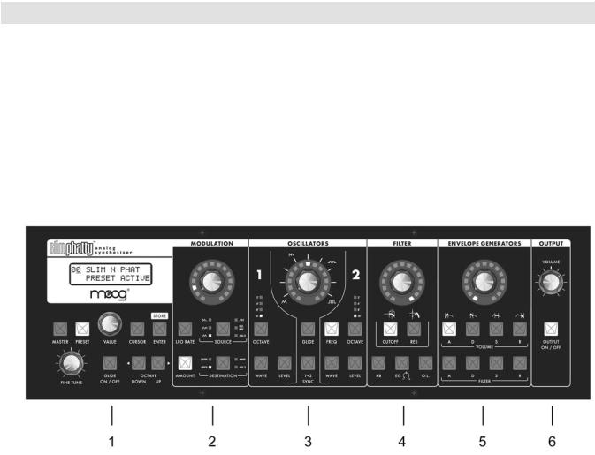
Here’s a brief description of the front panel components.
Front Panel:
1.The LCD display and User Interface - provides controls to access the presets, the arpeggiator, and other software functions. The Fine Tune control is located here, along with switches for Glide On/Off and Octave transpose.
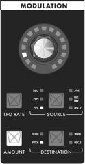
2.The Modulation section - features a programmable modulation matrix. The Modulation section has controls to select the modulation Source (LFO Triangle, LFO Square, LFO Sawtooth, LFO Ramp, Filter EG or Oscillator 2) the LFO Rate, the modulation Destination (Pitch, Filter, Waveform or Oscillator 2) and the modulation Amount parameters. Pressing and holding the AMOUNT switch enables the MODULATION control knob to act as a MOD WHEEL control.
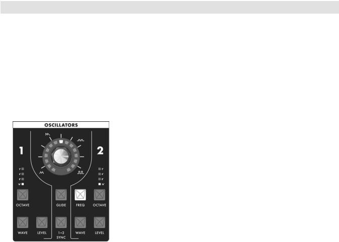
3.The Oscillators section - features two analog oscillators, each with individual Octave, Level and Waveform controls. Additional controls are provided for tuning the second oscillator relative to the first, setting the Glide Rate, and engaging Oscillator Hard Sync. The oscillator outputs are summed together along with the External Audio Input and routed to the Filter section.
4.The Filter section - features the classic Moog 24dB/Octave ‘ladder filter’, and includes controls for adjusting Cutoff Frequency, Resonance, Keyboard Amount, Envelope Amount, and Overload. The output
of the Filter is routed to the output Voltage Controlled Amplifier (VCA), which is controlled by the Volume Envelope Generator.
Page 8
Slim Phatty User’s Manual - The Basics
Front Panel (con’t):
5.The Envelope Generator (EG) section - contains two ADSR-style envelopes, one for the Filter and one for the Volume. The EG section includes controls for adjusting the Attack, Decay, Sustain and Release parameters of each envelope.
6.The Output section - includes controls for adjusting the Master Volume, and a switch to toggle the Audio output on and off. The Master Volume control simultaneously adjusts the levels of both the Audio output and the Headphone output on the back panel.
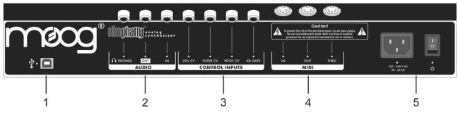
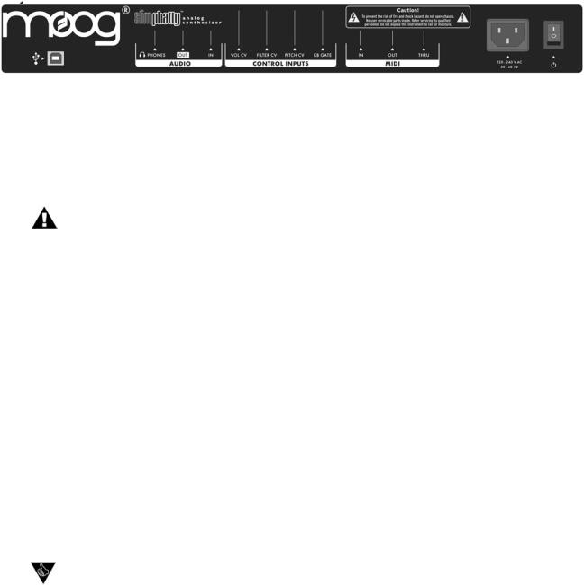
Back Panel:
The back panel provides connections for Power, MIDI, Control Voltage Input and Audio I/O.
1.MIDI USB - provides MIDI Input/Output to other MIDI devices through a standard USB ‘Type B’ connection.
2.Audio jacks – provides monophonic Audio Input and Output connections, as well as a Headphone output. The Audio Input jack allows external signals to be processed by the Slim Phatty.
3.Control Voltage jacks – provides Control Voltage/Expression Pedal inputs for Pitch, Filter, and Volume parameters, and a keyboard Gate input to trigger the envelope generators with a footswitch or gate signal. These inputs allow the SP to be controlled from an EP2 expression pedal, MP-201 Multi-Pedal, Etherwave Plus Theremin, or CV devices like the Moogerfooger® CP-251 Control Processor.
4.MIDI - provides MIDI Input/Output/Thru to other MIDI devices through standard MIDI DIN connections.
5.Power Socket and Switch – provides power to the SP.
Page 9
Slim Phatty User’s Manual - The Basics
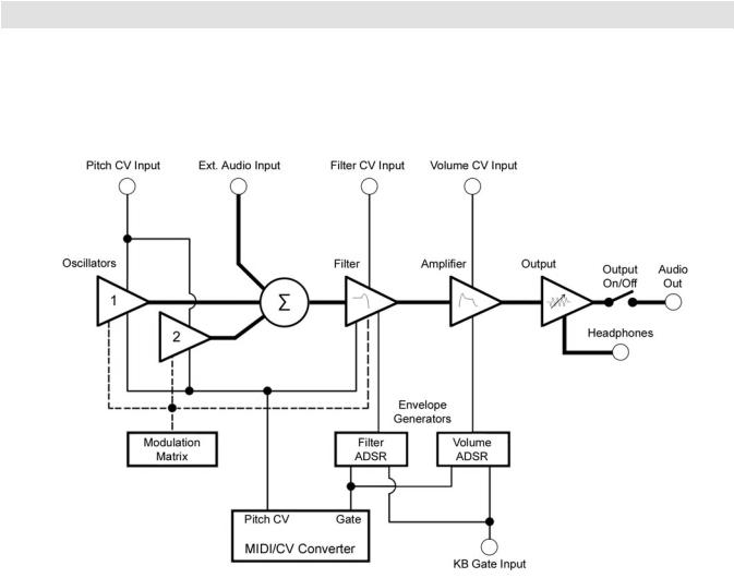
Signal Flow
To understand the operation of the Slim Phatty, refer to the diagram below. The diagram shows the flow of the audio, control voltage and modulation signals in the Slim Phatty. Heavy lines are used to indicate audio signals, which flow from left to right. Lighter lines indicate the control voltages (CV’s), which flow from the top and bottom. Dotted lines indicate programmable modulation routings.
As the diagram shows, the SP’s source signals are created by two voltage-controlled oscillators which are mixed together along with the external audio input. The combined audio signal is passed to the low-pass filter, where the tone is sculpted according to the settings of the filter parameters and the Filter ADSR envelope. The signal then passes to the amplifier stage, where the Volume ADSR envelope shapes it. Finally, the signal is routed to the output section, where the final level is set by the Master Volume control.
For many users, MIDI will be the main source of control for the Slim Phatty. Each time the SP receives a MIDI ‘Note On’ command, the SP produces a Pitch CV and Gate signal in response. The Pitch CV signal is used to specify the pitch of the oscillators, while the Gate signal is used to simultaneously trigger the Filter and Volume Envelope Generators.
The SP can also be operated via CV and Gate trigger connections, providing for a more ‘old school’ method of control.
Page 10
Slim Phatty User’s Manual - The Basics
Basic Operation
The SP has two operating modes: Master and Preset.
•Master mode allows you to access and change global parameters and other utility options. A complete list of the Master mode functions and parameters is shown on page 26.
•Preset mode allows you to access the presets and manipulate the sound from the front panel controls. The Preset mode is the main operating mode for editing and playing the SP. Information on Preset mode is found on page 23.
When the SP is powered on, it starts up in Preset mode. In this mode, you select presets using the VALUE encoder. You can rotate the VALUE encoder to step through the presets in either direction. Pressing the encoder while rotating increments the preset selection by +10 or -10 presets. In Preset mode, you’ll see the current preset displayed on the top line of the LCD display, and a ‘Preset Active’ message on the bottom line. The PRESET button is illuminated in red. When you edit a preset, the bottom line of the display changes to ‘Panel Active’ and the PRESET button changes from red to amber, indicating that you are editing the preset sound. By pressing the PRESET button you can toggle between the preset (stored) and edited (panel) sounds. Note that once you change preset numbers, any edits made to the previous preset will be lost unless the edits are saved.
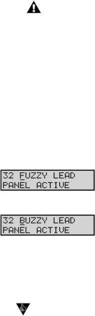
Editing a preset is simple. There are four analog editing controls on the front panel, one for each of the four sound shaping sections (Modulation, Oscillators, Filter, and Envelope Generators). Each control is surrounded by a ring of 15 LEDs that indicate approximately the stored or edited value of the current parameter. The parameters for each section are chosen by pushing the switch for the desired parameter in that section. That switch then becomes illuminated. Only one parameter can be activated at a time for editing in each section.
Some parameters offer multiple selections (such as the Modulation SOURCE switch, shown at right). Pressing that switch advances through the six possible Modulation sources. For the On/Off type switches like GLIDE ON/OFF (above), 1-2 SYNC or OUTPUT ON/OFF, the switch is illuminated when the parameter is turned on, and goes out when the parameter is turned off.
TECH NOTE: The SP’s editing controls are actually analog potentiometers. When certain key parameters are selected, the analog control signal is switched to control that parameter directly. This is called RAC™ (Real Analog Control). RAC gives the SP a responsiveness that can only be achieved with analog control by providing direct access to the analog control signal path; straight to the synthesizer circuits. RAC provides responsive analog control for the Osc 1 & 2, Filter Cutoff, Filter Resonance, EG Amount, Overload and Filter EG Sustain parameters.
Page 11
THE COMPONENTS
Slim Phatty User’s Manual - The Components
The Components
Now let’s take a look at the individual module components that make up the Slim Phatty Synthesizer, starting with the Oscillator section and moving right across the front panel, explaining the features and functions of the Filter, Envelope Generator and Output sections. Then we’ll cover the Modulation section, the Input/ Output Back Panel, and the User Interface section.
A. The Oscillator Section
The Oscillators are the main sound source of the Slim Phatty. The oscillators in the SP are analog Voltage Controlled Oscillators (VCOs) that feature a temperature regulation circuit that provides them with excellent tuning stability. The SP’s VCOs can produce a total musical range of 9 octaves!
Oscillator One serves as a master oscillator to which Oscillator 2 is tuned. The timbres of the oscillators are adjusted by their variable waveform (WAVE) controls. There is also a switch for syncing Oscillator 2 to Oscillator 1, and a control for adjusting the glide rate which is explained below.
The frequencies of the oscillators are controlled and affected by a number of sources. The main control source is a ‘NOTE ON’ command transmitted from an external MIDI controller. The MIDI ‘NOTE ON’ command is translated into a Control Voltage (CV) that allows the oscillators to be played in an equal tempered scale. Adding to that, the SP’s glide circuit can be switched on to slow the CV changes between notes, resulting in portamento. The CV is then mixed with the Octave switch CV, the Frequency offset control (Oscillator 2), the Pitch CV In (if plugged in on the back panel), the fine tune control, and the output of the Mod Matrix when the “Pitch” destination is selected.
Oscillator Section Controls:
Octave:
Each Oscillator has a switch labeled OCTAVE that selects the relative frequency range. To select the octave, simply press the switch. Each press of the switch advances the setting, as indicated by the corresponding LED. When the topmost octave is reached, the next button press cycles back to the lowest octave. The panel markings 16’, 8’, 4’ and 2’ are octave standards based on organ stops. On the 16’ setting the highest A on the keyboard is A440.
Oscillator Level:
Each oscillator has a switch labeled LEVEL that allows the analog edit control to adjust the oscillator level. This allows you to control the relative strength of each oscillator in the mixer from 0 to 100%.
Page 12
Slim Phatty User’s Manual - The Components
Waveform:
Each oscillator has a switch labeled WAVE that allows the analog edit control to modify the waveform. The waveform is continuously variable from triangle, to sawtooth, to square, to rectangular. The waveform is morphed gradually from one to another as the value control is rotated. The legend around the analog edit control for the oscillator section indicates the knob positions to obtain the triangle, sawtooth, square and skinniest pulse waveforms. Because the waveform is voltage controlled, this parameter can be modu-
lated. This allows the generation of some very interesting timbral changes. By limiting the modulation between the square and thin rectangle (pulse) waves, you can get pulse width modulation, a classic analog synthesizer sound. Although the waveforms can be set from the front panel individually for each oscillator, modulation is applied to both waveform controls simultaneously. When modulation is applied, it is possible to make the width of the rectangular wave so skinny that it becomes silent.
Frequency:
Oscillator 2 has a switch labeled FREQ that allows the analog edit control to adjust the frequency
of Oscillator 2 relative to Oscillator 1. The pitch of Oscillator 2 can be adjusted up or down 7 semitones (± a fifth). By changing the pitch of Oscillator 2, more than one frequency can be played when a key is pressed, creating intervals for large adjustments, or to get a chorus sound when the oscillators are just slightly out of tune. Note that Oscillator 1 does not have a frequency control because it is designed to serve as a reference oscillator.
Sync:
In the center of the oscillator panel is a switch labeled 1–2 SYNC. This is simply an ON/OFF type switch that has no interaction with the analog edit control. Sync is ON when the 1-2 SYNC switch is lit. With sync on, Oscillator 2 is synchronized (hard synced) to Oscillator 1, forcing Oscillator 2 to restart its wave-
form from the beginning each time Oscillator 1 starts a new waveform cycle. The effect is noticeable if the synced Oscillator is a higher frequency than the Reset Oscillator. The main frequency heard is that of the reset oscillator. As the frequency of the synced oscillator is swept, it reinforces the harmonics of the reset oscillator. Use the Oscillator 2 Frequency control to hear this effect. Depending on how it is applied, the effect can be aggressive or warm and vocal.
Glide Rate:
In the center of the oscillator panel is a switch labeled GLIDE. When this is selected, the analog edit control is used to set the glide rate (portamento) between notes. A Glide switch on the User Interface panel (on the far left) turns the Glide effect on or off. Glide is the time it takes to go from one note to the next. The glide rate can vary from virtually instantaneous to a very slow glide (about 5 seconds to go from the lowest C to the highest C on the keyboard).
Additional CV control:
The PITCH jack on the back panel is a CV input for external control of the oscillator pitch. This input controls the frequencies of both oscillators. A 1-volt change of this voltage will change the pitch by NOMINALLY one octave. The jack accepts -5 to +5 volts, or an expression pedal like the EP-2.
PERFORMANCE TIP: A steady control voltage applied to the PITCH jack will offset the base pitch of both oscillators. You can use this feature to transpose the keyboard to any desired interval applying the appropriate steady-state CV. See Appendix J for more information on how to con gure this.
Page 13
Slim Phatty User’s Manual - The Components
B. The Filter Section
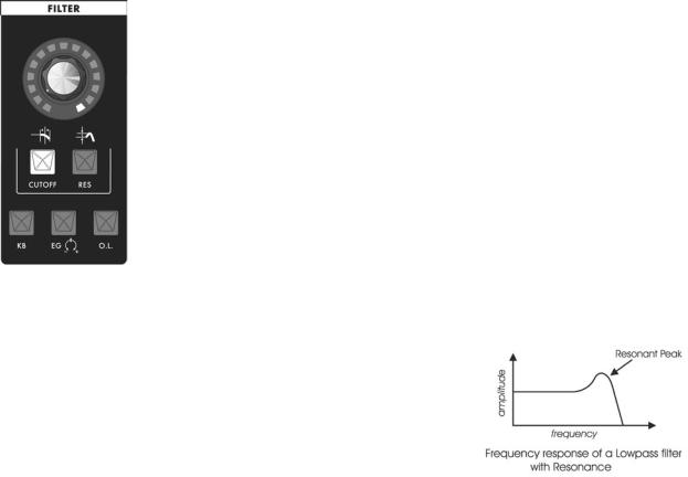
Filters are used for adjusting the timbre of an audio signal. Filters modify sound by attenuating some frequencies while allowing others to pass through unaffected. An important term to understand regarding filters is “Cutoff Frequency”. This is the point at which frequencies begin to be rejected. The SP features a lowpass filter, which behaves as its name indicates: it allows low frequencies to pass and rejects high frequencies.
Another important aspect of filters is the cutoff slope. The cutoff slope defines how well the filter rejects signals above the cutoff frequency. The cutoff slope is measured in decibels per octave (dB/Octave), and is always specified as a multiple of six. A 6dB/Octave slope–the simplest possible filter design–exhibits a gentle roll-off with a minimum rejection of frequencies above the cutoff. By comparison, a 12dB/Octave slope is twice as steep, and rejects frequencies above the cutoff twice as much. An 18dB/Octave slope is steeper still, with a corresponding frequency rejection. Finally, a 24dB/Octave slope provides the steepest rejection of frequencies above the cutoff point. The classic Moog ‘ladder’ filter is a 24dB/Octave lowpass filter.
The Moog filter also features a parameter called Resonance. This parameter adds a resonant peak at the cutoff frequency. When the resonant peak passes through the overtones of the sound being filtered, those overtones are reinforced. This gives the filter a character that can sound nasal, buzzy, raspy, etc., depending on how it’s used. When the resonance is turned up past about 3 o’clock on the dial, the filter begins to self-oscillate at the cutoff frequency, producing a sine wave tone.
Other filter section controls include Keyboard Amount (KB), Envelope
Generator Amount (EG) and Overload (O.L)
The KB parameter allows you to set the degree to which the filter cutoff frequency tracks the note that is played. For example, when KB is set to it’s highest level (100%), the filter cutoff will rise by an octave each time you play an octave higher on the keyboard. This setting allows you to maintain a consistent filter tone regardless of whether you play low or high on the keyboard. When KB is set to zero, the filter cutoff remains at the value determined by the analog edit control, regardless of where you play on the keyboard.
This can make the sound less bright as you play higher up on the keyboard. The KB parameter includes the keyboard GLIDE control signal, which allows the filter cutoff to follow the glide of the notes being played (when GLIDE is switched ON). Using the KB control, you can adjust the amount of Glide that will affect the filter cutoff.
The EG parameter allows you to set the degree to which the Filter EG affects the filter cutoff frequency. The EG parameter is bi-polar, meaning the Filter EG can affect the filter cutoff either in a positive or negative manner. A positive EG amount will raise the cutoff frequency, while a negative EG amount will lower it.
Page 14
Slim Phatty User’s Manual - The Components
Finally, the Overload (O.L.) parameter allows you to set the amount of signal clipping from none to soft to hard clipping as the amount is increased. The results you get with Overload will depend on the settings of the oscillator waves and levels, and the filter cutoff and the filter resonance settings in addition to Overload amount. Note that Overload is not the same distortion you’d get from a fuzz box. It can be quite subtly applied to add just a touch of ‘bite’, or aggressively applied to add a jagged edginess to the sound.
Filter Section controls:
Cutoff:
When the CUTOFF switch is selected, the analog edit control is used to adjust the filter cutoff frequency. The cutoff frequency is adjustable from about 20 Hz to 16 Khz. As the edit control is rotated clockwise, the cutoff frequency is increased, allowing more of the signal harmonics to pass through the filter.
Resonance (RES):
When the RES switch is selected, the analog edit control is used to adjust the filter resonance. Resonance causes feedback in the filter circuit, adding harmonic emphasis at the cutoff frequency. When the Resonance control is all the way down, the lowpass filter acts basically as a tone control, rolling off the high end of the signal as the Cutoff control is turned down. As Resonance is increased, the filter begins to form a peak at the cutoff frequency. This emphasizes harmonics near the cutoff frequency, and can result in a ‘wah-wah’ effect when resonance is set fairly high and the filter cutoff is varied. As the resonance is turned up the peak increases in strength until it begins to self-oscillate – creating a sine wave with the same frequency as the cutoff frequency.
Keyboard Control Amount (KB):
When the KB switch is selected, the analog edit control is used to adjust the amount of post-glide keyboard voltage that is routed to the filter cutoff frequency. When the edit control is rotated fully clockwise, the filter cutoff follows the key played on the keyboard. A higher key will cause a higher cutoff frequency.This allows a sound to retain its brightness as it is played higher on the keyboard.
Envelope Generator Amount (EG):
When the EG switch is selected, the analog edit control adjusts the amount of the Filter Envelope Generator output that affects the filter cutoff. The Envelope Generator Amount is bi-polar, as indicated by the legend on the panel, so the amount is 0 when the edit control dial is at the 12 o’clock position. Rotating the control CW from that point adds a positive EG amount to the filter cutoff, while rotating the control CCW from that point adds a negative amount to the filter cutoff.
Overload (O.L):
When the O.L. switch is selected, the analog edit control adjusts the amount of pre-filter and post-filter clipping. Overload can be used to warm up sounds and give them a distinctive tonal edge. Advancing the edit control increases the amount of clipping from the subtle warmth of soft clipping to the ‘growl’ provided by the beginnings of hard clipping. When set to 100%, Overload adds a volume boost of about +6dB.
Additional CV control:
The FILTER jack on the back panel is a CV input for external control of the filter cutoff parameter. The jack accepts -5 to +5 volts, or an expression pedal like the EP-2. A voltage applied to this jack is added to the setting of the filter cutoff control. A one-volt change in the control voltage will change the cutoff frequency of the filter by about one octave.
Page 15
Slim Phatty User’s Manual - The Components
TECH NOTES:
1.The SP’s Overload circuit uses asymmetrical clipping, which clips each side of the waveform differently. Asymmetrical clipping circuits tend to produce tones with unique richness and character.
2.The Overload circuit has no effect on the sound when the analog edit control is set fully counterclockwise. Advancing the control gradually introduces the effect, starting with a gentle overdrive-like quality that becomes increasingly aggressive and edgy as the control reaches 100%. Because the Overload uses clipping, some sounds, such as a square wave with the lter cutoff all the way up, aren’t affected much by increasing the Overload amount. Try sounds tuned to intervals other than unison, and a slightly resonant lter setting to really hear the effect.
3.The name “Overload” came from the Overload indicator on the Minimoog, where if the output was patched back into the audio input the Overload indicator would go on. Mixing the Audio in would provide a “fatter” sound by increasing the level of signal coming out of the mixer and going into the lter.
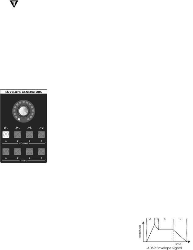
C.The Envelope Generators Section
Musical sounds have a start, a middle and an end. For example, a plucked string sound starts with an initial burst of energy and then slowly fades out until it is silent. In synthesis terms, this progression is called an envelope – a shape that defines the changes that occur in a sound over time. An envelope can define any aspect of change in a sound – volume, timbre, or pitch. The circuits that create envelope control signals in synthesizers are called Envelope Generators (EGs).
The Slim Phatty has two identical EG circuits. When triggered, these circuits produce time-varying control voltages having a start, a middle and an end. The parameters that specify this progression are the Attack, Decay, Sustain and Release controls, abbreviated as ADSR.
Attack determines the fade-in of the envelope. The Attack control adjusts the time it takes for the envelope to go from zero to full value (in other words, the fade-in time) when the EG is triggered. After the Attack segment completes, the Decay control takes over, adjusting the second stage in the evolution. Decay is the time that it takes for the signal to drop from the full level to the level set by the Sustain control. Once the sustain level is reached, it will remain there as long as the trigger signal is present. When the trigger is finally released, the Release control determines how long it takes for the envelope to return to zero (see the ADSR Envelope Signal).
The Slim Phatty has two envelope generators; one EG is dedicated to the amplifier (to control the volume), and one EG is dedicated to the filter (to control the cutoff frequency).The Filter EG can also be used as a modulation source through the Modulation Matrix.
Page 16

Slim Phatty User’s Manual - The Components
Envelope Generator Section Controls:
Attack:
When the ATTACK switch is selected, the analog edit control is used to adjust the Attack time of the corresponding envelope from 1 msec to 10 seconds.
Decay:
When the DECAY switch is selected, the analog edit control is used to adjust the Decay time of the corresponding envelope from 1 msec to 10 seconds.
Sustain:
When the SUSTAIN switch is selected, the analog edit control is used to set the Sustain level of the corresponding envelope.
Release:
When the RELEASE switch is selected, the analog edit control is used to adjust the Release time (the time for the envelope to return to zero) from 1 msec to 10 seconds.
Additional Control:
The KB GATE jack on the side panel is a trigger input that accepts a footswitch (momentary, normally closed like the Moog FS-1) or a gate signal. Pressing the footswitch or applying a gate signal (+5V) causes both envelopes (Volume and Filter) to trigger.
PERFORMANCE TIP: Plugging a FS-1 footswitch into the KB GATE jack allows you to trigger or sustain a note using your foot without playing the keyboard – useful if you want to free-up both hands to modify two panel functions at once.
Page 17
Slim Phatty User’s Manual - The Components
D. The Modulation Section
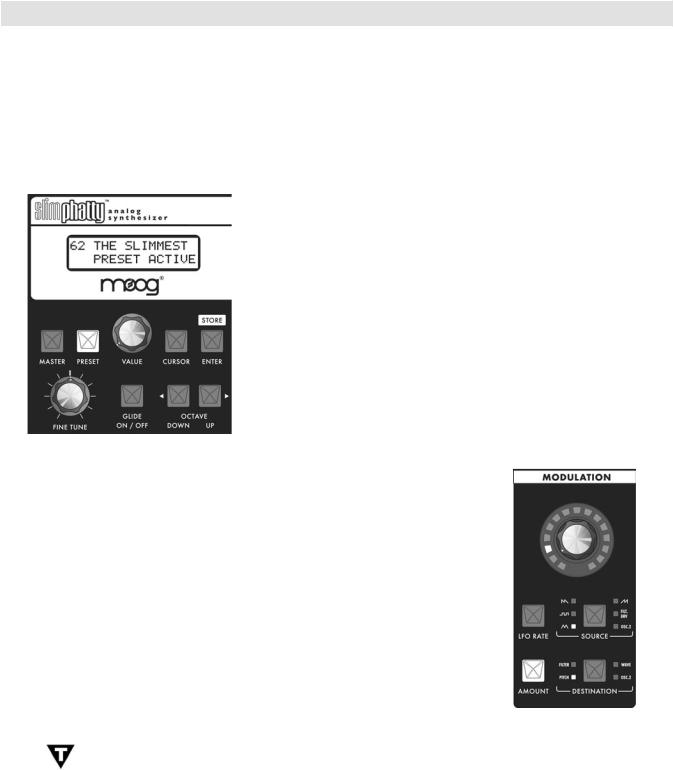
Modulation is the heart of making interesting sounds with analog subtractive synthesis. The SP’s Modulation section opens up a world of modulation possibilities that were not available on the original Minimoog. The Modulation section allows you to select from six modulation sources, specific one of four destinations, and set the modulation amount. The output of the Modulation section is controlled by the Modulation Wheel of your MIDI controller. You can also enable the MODULATION control knob to act as a Modulation Wheel control by pressing and holding the AMOUNT switch.
To try out a simple modulation effect, make the following settings:
-Set the LFO RATE to 6 Hz (about 11 o’clock on the analog edit control)
-Set the SOURCE to Triangle wave
-Set the DESTINATION to Pitch
-Set the AMOUNT to 50% (about 10 o’clock on the analog edit control)
These settings will produce a vibrato effect with variable depth when the
Modulation Wheel is engaged.
Section Controls:
LFO Rate:
When the LFO RATE switch is selected, the analog edit control is used to adjust the frequency of the LFO. The frequency is adjustable from 0.2 Hz to 500 Hz. Since the LFO rate extends well into the audio range, this allows the LFO to be used for clangorous (FM-like) modulations. Pressing and holding the LFO RATE switch enables the Tap Tempo function. When Tap Tempo is enabled, the LFO RATE switch will blink on and off. To escape this function, press and hold the LFO RATE switch until the light stops blinking. For more on the Tap Tempo function, see Tap Tempo on page 25.
Amount:
When the AMOUNT switch is selected, the analog edit control is used to adjust the maximum amount of modulation controlled by the Modulation Wheel. Pressing and holding the AMOUNT switch enables the MODULATION control knob to act as a MOD WHEEL controller. When the MOD WHEEL function is enabled, the AMOUNT switch will blink on and off. To escape this function, press and hold the AMOUNT switch until the light stops blinking.
Source:
The SOURCE switch selects the source of the modulation. Each time the switch is pressed, it advances to the next modulation source, as indicated by the corresponding LED. Four of the selections allow you to use the LFO as a modulation source. When any of the LFO waves is selected, the associated LED will flash in time with the LFO rate. The available Source selections are:
-LFO Sawtooth Wave
-LFO Square Wave
-LFO Triangle Wave
-LFO Ramp Wave
-Filt. Env. (Filter Envelope)/Sample & Hold
-Osc 2 (Oscillator 2)/Noise
Page 18

Slim Phatty User’s Manual - The Components
The Modulation Section (con’t)
Destination:
The DESTINATION switch selects the destination of the modulation.The modulation destination is chosen in the same manner as the source.The modulation destination selections are:
-Filter (affects filter cutoff)
-Pitch (affects the pitch of both oscillators)
-Wave (affects the waveform of both oscillators)
-Osc 2 (affects the pitch of Oscillator 2)
E.The Output Section
The Slim Phatty features a monophonic audio output and a headphone output. Both of these outputs appear on the back panel. The level of both outputs is adjusted simultaneously by the Volume Control. An On/Off switch allows you to turn off the signal at the audio output jack while keeping the Headphone signal active.
Section Controls:
Volume:
VOLUME is the main volume control. Rotating the control fully clockwise produces the maximum output. Rotating the control fully counterclockwise silences the Slim Phatty. The VOLUME control setting is not stored with the preset.
Output On/Off:
The OUTPUT ON/OFF switch controls the signal that appears at the audio output jack. This switch has no effect on the Headphone output. This arrangement allows you to silence the audio output while you monitor and adjust the sound of the SP using headphones. The output is ON when the switch is lit.
Additional CV control:
The VOL CV jack on the back panel is a CV input for external control of the Output level. The jack accepts a positive control voltage from 0 to 5 Volts, or an expression pedal like the Moog EP-2. A voltage of 0 volts silences the SP, and a voltage of 5 volts corresponds to the output level set by the VOLUME control knob.
Page 19
Slim Phatty User’s Manual - The Components
F. Input/Output Panel
The Back Panel provides all of the input and output connections. In addition to Audio Input/Output jacks, there are CV and Gate inputs, connections for MIDI, and the power connector and power switch.
Power Connector:
This is a standard AC power inlet, Use only a power cord designed to mate with this receptacle. The Little Phatty’s built-in universal power supply is designed to work with power inputs of 90-250 Volts AC, 50/60 Hz.
IMPORTANT SAFETY NOTE – Do not alter the power connector in any way. Doing so can result in the risk of shock, injury or death. Be familiar with the safety instructions printed at the beginning of this manual. If the connector is damaged, refer servicing to quali ed personnel only.
Audio IN:
The Audio In jack allows an external audio source to be mixed with the SP’s VCOs, and then routed to the filter for processing. The SP has no provisions for adjusting the level of this input, it must be controlled externally. The audio input is designed to distort as the level of the external audio gets very high, adding color to the sound.
Audio OUT:
The Audio Out jack provides an unbalanced line-level signal for connecting to an amplifier or mixer.
CV Inputs:
The Pitch, Filter and Vol (Volume) CV jacks supply power and will accept an expression pedal such as the Moogerfooger EP-2 (ring = +5.5 supply to the pedal, tip = variable CV return), or a control voltage from –5 to +5 Volts. The KB Gate Input accepts a footswitch (a momentary, normally-closed footswitch like the Moog FS-1) or a +5 Volt Gate Signal.
MIDI Connectors (DIN and USB):
These are DIN connections for MIDI In/Out/Thru, and MIDI USB connector. MIDI I/O is configurable for either connection type. For more information on configuring MIDI, see page 32.
PERFORMANCE TIPS:
1.You can use the SP to process any audio signal simply by plugging into the Audio IN jack. To hear the external audio signal without having to hold down a key on the keyboard, plug a dummy plug (or a patch cord with nothing connected to the other end) into the KB Gate jack. This will leave the keyboard gate open, and the volume envelope will remain at its Sustain level until the keyboard gate closes. Due to the design of the envelope circuits, you will need to turn the envelope Decay parameter down below 12:00 in order for the Sustain level to remain constant. If you notice that the volume of the external signal begins to slowly fade away, check to be sure the envelope Decay parameters are not set too high.
2.The SP’s Audio Input is not limited to processing monophonic signals - it can work well for processing polyphonic signals, too. For example, connect the MIDI Out of the SP to the MIDI Input of another polyphonic keyboard, then feed that audio output back into the SP through the Audio In jack. Now you have a POLYPHONIC source that is being affected by the SP’s Filter, Overload and EGR circuits.
Page 20

Slim Phatty User’s Manual - The Components
G. Interface Panel
The Interface Panel is located on a far left of the instrument. The
Interface Panel provides a status display and controls for all of the
Slim Phatty’s software functions and instrument settings.
The status display is an LCD screen located in the center of the panel above the section controls. When the SP is first powered on, the screen will display the message:
Slim Phatty
Version X.x
The message will stay on the screen for a few seconds, and then the screen will display the active preset. This preset will be the last preset in use when the Slim Phatty was powered down.
Section Controls:
Master:
Pressing the MASTER switch places you in Master mode. In this mode, the VALUE knob is used to scroll through the Master mode menus for the Slim Phatty. For a list of the Master mode menus, see page 26.
Preset:
Pressing the PRESET switch places you in Preset mode. In this mode, the VALUE knob is used to select the preset.The PRESET switch also functions as ‘compare’ button, allowing you to toggle between stored and edited presets. For more on Preset Mode, see page 23.
Value:
The VALUE knob is a continuous rotary encoder used to access menus and options, and select presets. Depending on the selected parameter, the VALUE knob will adjust numeric values UP or DOWN, or toggle amongst discrete options. The encoder has a built-in push button (called the VALUE pushswitch) that is used to advance through the presets in Performance Sets and for stepping though Master menu submenus. When naming a preset, the VALUE pushswitch will advance the cursor to the next letter.
Cursor:
The CURSOR switch is used to navigate around the display. In Master mode, the cursor is used to advance through the parameters in the display, allowing you to make edits and changes. In Preset Mode, the cursor is used to enter the Preset naming operation. Press CURSOR to get into cursor mode, and press MASTER or PRESET to exit cursor mode.
Page 21
Slim Phatty User’s Manual - The Components
Enter/Store:
The ENTER/STORE button is used to enter changes and store edited presets in PRESET mode and to execute SysEx and System Utility functions in MASTER mode.
Fine Tune:
The FINE TUNE control is used to tune the Slim Phatty’s oscillators ±3 semitones for matching an external reference pitch.
Glide On/Off:
The GLIDE ON/OFF switch enables or disables the glissando effect between notes. Glide is ON when the switch LED is lit. The glide rate is set using the GLIDE RATE control in the oscillator section.
Octave Up/Down:
The OCTAVE UP and OCTAVE DOWN switches transpose incoming MIDI notes up or down by octaves. The range is –2, -1, 0, +1, +2. Pressing either switch once will light the switch red and adjust the octave accordingly. Pressing the same switch a second time will adjust the octave again and change the illumination from red to amber, indicating that a two-octave change has been selected. The Octave settings in the Slim Phatty are not stored per Preset, rather, they affect the operation of the SP globally.
Page 22
THE USER INTERFACE
Slim Phatty User’s Manual - The User Interface
Preset Mode
Preset mode is the default mode when the SP is powered on. Preset Mode is used to access presets and provide control for editing, naming and storing sounds.
Preset sounds are selected using the VALUE knob. As the VALUE knob is advanced, the next preset appears in the display and is immediately available to be auditioned (you do not need to ‘activate’ the preset to hear it). Pressing VALUE and turning the knob will advance by increments of ten.
You can use the front panel controls to edit the sound at any point. Changing any of the front panel controls will automatically switch the lower part of the display from ‘PRESET ACTIVE’ to ‘PANEL ACTIVE’, indicating that the preset has been modified. The PRESET light also changes its illumination from red to amber, indicating that the sound you hear is an edited version of the stored preset
You can toggle between the stored and edited sound by pressing the PRESET button. This acts like a COMPARE function, allowing you to compare the sound of the original and edited presets. When using the COMPARE function, the PRESET button will alternate colors and the LCD will display either ‘PRESET ACTIVE’ (the original sound) or ‘PANEL ACTIVE’ (the edited sound).
NOTE: When switching between Master and Preset modes, the last used preset appears in the display.
Storing Presets
To store a preset, press the ENTER button. This button doubles as the STORE button in Preset mode as indicated on the front panel. Store is used to save an edited preset (Panel Active), or to change the location of a stored preset (Preset Active).
When you press STORE, the LCD will display a message similar to the one shown at left. The top line shows the location where the preset will be saved, and the name of the preset that is currently stored in that location. Use the VALUE knob to change to the desired preset location, then press the CURSOR to move the cursor to the lower line of the LCD. A default setting of ‘OVERWRITE: NO’ as shown protects you from accidently overwriting a favorite preset. If you decide that you
do not want to save the preset, press ENTER and the SP will return to Panel Mode without saving.
If you are sure you want to save the preset to the selected location, use the VALUE knob to select ‘OVERWRITE:YES’ and press ENTER. The SP will display the ‘PRESET STORED’ message confirming that your preset was saved successfully.
Page 23
Slim Phatty User’s Manual - The User Interface
NOTE: When the Arpeggiator is running, the ENTER/STORE button is also used to activate the latch if the Latch parameter has been enabled. For more on the Arpeggiator and Latch functions, see page 40.
Changing A Preset Name
Changing a preset name is a simple operation. The characters in a name are individually selected by moving the cursor to the desired location and scrolling through the character list. To change a preset name, press the CURSOR button until it advances to the first letter of the name. Use the VALUE knob to select the desired character or number. Press the VALUE pushswitch to advance the cursor to the next letter. Repeat this action until all desired characters have been changed.
Preset names consist of any combination of 13 letters, numbers and punctuation characters. In order, the available characters are:
(space) A B C D E F G H I J K L M N O P Q R S T U V W X Y Z 0 1 2 3 4 5 6 7 8 9 a b c d e f g h i j k l m n o p q r s t u v w x y z ! # $ % & ( ) * ? @
Press the CURSOR button once to select the first character in the name as shown.
Use the VALUE knob to select a new character as shown. Use the VALUE pushswitch to advance to the next character, then use the VALUE knob to select the next character. Continue in this manner until the desired name change is complete. When finished, press the STORE button to enter the name change into memory. Select the desired memory location, select ‘OVERWRITE:YES’, and press STORE to save the new name.
PERFORMANCE TIP: When a preset is stored, the ‘ON’ status of the active parameter in each of the four sections is also stored. For example, if Cutoff was the active lter parameter when the preset was stored, it will become the active lter parameter again when the preset is recalled. By saving your presets with this in mind, you can have the four analog edit controls automatically set to the desired parameters when the preset is recalled. This is a great feature if you need to tweak the sound in live performance!
Page 24
Slim Phatty User’s Manual - The User Interface
Tap Tempo
Tap Tempo is an easy and intuitive way to adjust the speed of the LFO Rate or the Arpeggiator Clock. The Tap Tempo function is always available for any preset in PRESET Mode. Tap Tempo can be used to adjust the LFO Rate when the Arpeggiator is not running, or adjust the Arpeggiator Clock when the Arpeggiator is running.
To enter Tap Tempo Mode, press and hold the LFO RATE button until it starts flashing rapidly; this indicates that Tap Tempo Mode is active.
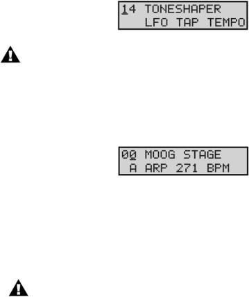
When Tap Tempo is active and the Arpeggiator is not running, tapping the LFO RATE button will set the internal LFO Rate and override the LFO Sync Mode (see ‘LFO SYNC’ on page 27). Both the LFO LED and the LFO RATE button will begin flashing at the new rate, and the bottom line of the LCD will display a status message indicating that the Tap Tempo function is active:
NOTE: Once activated, Tap Tempo will remain activate even if you change presets. The Tap Tempo rate from the previous preset will not be transferred to the new preset, however.
When Tap Tempo is active and the Arpeggiator is running, tapping the LFO RATE button will set the rate of the Arpeggiator Clock. Both the LFO LED and the LFO RATE button will begin flashing at the new rate, and the LCD will display the new rate in BPM:
If the MODULATION control knob is adjusted while in Tap Tempo Mode, it will override the Tap Tempo and adjust the LFO Rate or Arpeggiator Clock to the new value.
To exit Tap Tempo Mode, press and hold the LFO RATE button until it stops flashing. This will return to the previous mode (either free running or MIDI clock).
NOTE: If the Arpeggiator is set to ‘MIDI CLOCK’ when Tap Tempo is active, Tap Tempo will adjust the internal LFO Rate and not the Arpeggiator Clock.
Page 25
Loading...