


This manual is a living document that will be updated frequently.
Please visit www.moogmusic.com/moogone to find the most up to date manual. If you are having trouble finding specific information about your Moog One in this manual please email: moogonemanual@moogmusic.com for assistance.


“ M u s i c a l i n s t r u m e n t s p r o v i d e t h e m o s t e f f i c i e n t a n d r e f i n e d i n t e r f a c e b e t w e e n h u m a n a n d m a c h i n e o f a ny t h i n g w e k n o w.
- Dr . Robert Moog -
3
IMPORTANT SAFETY INSTRUCTIONS
WARNING - PLEASE BE ADVISED THAT THIS INSTRUMENT WEIGHS 45 POUNDS, AS SUCH WE RECOMMEND THAT TWO PEOPLE REMOVE THE INSTRUMENT FROM THE BOX AS A SAFETY PRECAUTION. PLEASE DON’T ATTEMPT TO MOVE THE INSTRUMENT BY YOURSELF.
WARNING - WHEN USING ELECTRIC PRODUCTS, THESE BASIC PRECAUTIONS SHOULD ALWAYS BE FOLLOWED.
1.Read all the instructions before using the product.
2.Do not use this product near water - for example, near a bathtub, washbowl, kitchen sink, in a wet basement, or near a swimming pool or the like.
3.This product, in combination with an amplifier and headphones or speakers, may be capable of producing sound levels that could cause permanent hearing loss. Do not operate for a long period of time at a high volume level or at a level that is uncomfortable.
4.The product should be located so that its location does not interfere with its proper ventilation.
5.The product should be located away from heat sources such as radiators, heat registers, or other products that produce heat. No naked flame sources (such as candles, lighters, etc.) should be placed near this product. Do not operate in direct sunlight.
6.The product should be connected to a power supply only of the type described in the operating instructions or as marked on the product.
7.The power supply cord of the product should be unplugged from the outlet when left unused for a long period of time or during lightning storms.
8.Care should be taken so that objects do not fall and liquids are not spilled into the enclosure through openings.
There are no user serviceable parts inside. Refer all servicing to qualified personnel only.
NOTE: This equipment has been tested and found to comply with the limits for a Class B digital device, pursuant to part 15 of the FCC Rules. These limits are designed to provide reasonable protection against harmful interference in a residential installation. This equipment generates, uses and can radiate radio frequency energy and, if not installed and used in accordance with the instructions, may cause harmful interference to radio communications. However, there is no guarantee that interference will not occur in a particular installation. If this equipment does cause harmful interference to radio or television reception, which can be determined by turning
the equipment off and on, the user is encouraged to try to correct the interference by one or more of the following measures:
—Reorient or relocate the receiving antenna.
—Increase the separation between the equipment and receiver.
—Connect the equipment to an outlet on a circuit different from that to which the receiver is connected. —Consult the dealer or an experienced radio/TV technician for help.
CAUTION: Please note that any changes or modifications made to this product not expressly approved by Moog
Music Inc. could void the user’s authority granted by the FCC to operate the equipment.
TABLE OF CONTENTS
07 UNPACKING AND INSPECTION
07 SETUP AND CONNECTIONS
08 MOOG ONE OVERVIEW
09Presets, Synths, And Performance Sets
09Voice Architecture
10PILOTING MOOG ONE
10 Front Panel
17 Keyboard And Left Hand Controller
19 Rear Panel
22 MOOG ONE MODULES
22 Oscillators
29 Noise
31 Mixer
33 Filters
40 Envelopes
46 Low Frequency Oscillators
51 VCA
53 Output
57 Performance Set
61 Master Clock
63 Voice Allocation (Hold/Chord/Polyphony)
67 Modulation
78 Arpeggiator
82 Sequencer
96 Effects
112 Left Hand Controller
118THE BROWSER
119Loading A Preset
119Loading A Timbre
120Saving Presets And Synth Timbres
122EDITING AND SAVING
122Compare
122Snapshot
123Autosave
124SETTINGS
124 Global
129 MIDI Control
132CV Inputs
133CV Outputs
134Utilities
135Library
140Tuning
141 SPECIFICATIONS
143 SERVICE AND SUPPORT
This page left intentionally blank
UNPACKING AND INSPECTION
Use caution when unpacking your new Moog One, and be sure that nothing is lost or damaged. Moog recommends saving the carton and all packing materials in case you ever need to ship the instrument for any reason.
CONTENTS
In addition to the instrument itself, your new Moog One also ships with the following items:
1.Power adapter and connecting power cord
2.Owner’s Manual
3.Registration Card
SETUP AND CONNECTIONS
Before you begin exploring your Moog One, you will need to provide the instrument with power, and connect it to an audio monitoring system so that you can hear it.
WHAT YOU WILL NEED
1.A stand or table capable of supporting Moog One (which weighs about 45 lbs.)
2.A properly wired and grounded AC outlet
3.Two 1/4” balanced TRS to TRS or TRS to XLR cables for connecting Moog One to an audio monitoring system, or stereo headphones outfitted with a 1/4” TRS (Tip/Ring/ Sleeve) plug may be used in either of the front Headphone jacks.
NOTE: Moog One is equipped with balanced outputs, so use either 1/4” TRS to 1/4” TRS cables or 1/4” TRS to XLR cables for the best results. Unbalanced 1/4” TS to 1/4” TS instrument cables may also be used, but are not recommended.
CONNECTING THE POWER SUPPLY
Moog One uses a universal power supply that can accommodate AC power sources ranging from 100 to 240 volts, and either 50 or 60 cycles (Hz). The included power supply features a detachable IECstyle power cable.
1.Connect the included IEC power cable to the Moog One power supply.
2.Connect the power supply cable to the 19-volt DC locking connector on the rear panel of Moog One.
3.Connect the other end of the power cable to a suitable AC wall outlet with a protective earth ground connection.
4.Finally, use the power switch on the rear panel to turn on your new Moog One.
NOTE: The power supply connects to your Moog One using a locking connector. To release this connector from the instrument, simply press the locking tab at the base of the connector and gently slide out the connector plug. Never pull on the cable, only the plug.
AUDIO MONITORING
With the Moog One MASTER VOLUME knob turned all the way down, connect one 1/4” cable to the MAIN L output, and the other 1/4” cable to the MAIN R output, then connect the opposite ends to a pair of L/R inputs on an amplified speaker system or mixing console. Adjust the Moog One volume level by slowly turning the MASTER VOLUME knob clockwise while playing the keyboard.
If you’re using headphones, turn the HEADPHONES knob all the way down before plugging them into either of the two headphone jacks (located on the front edge of the Left Hand Controller panel). Adjust the volume level by slowly turning the HEADPHONES knob clockwise while playing the keyboard.
NOTE: It may take up to 5 minutes for Moog One to warm up before Oscillator tuning has stabilized, especially if it has been outside in a car on a cold night. (Although its Oscillators are very stable,
Moog One is an analog synthesizer, after all.)
7
MOOG ONE
Designed to exceed every expectation, Moog One is the first polyphonic instrument from Moog in decades. From the original napkin sketches to the day we boxed the first unit for shipment from the
Moog Factory here in Asheville, North Carolina, the goal has remained to create an analog, polyphonic, programmable, and multitimbral synthesizer that is without equal. Realizing the Moog One vision
has been a journey of collaboration and discovery; a sharing of ideas between the Moog Team and countless artists, sound designers, and synthesizer enthusiasts from around the globe. In crafting
Moog One, it was paramount to keep the interface intuitive and tactile. The hope is that your sonic explorations will transcend the separation of artist and instrument, allowing Moog One to be the conduit for your own creative voice.
Moog One is an analog, polyphonic, programmable, and multitimbral synthesizer; each of these terms carries its own significance and its own legacy.
ANALOG
The heart of the Moog One sound is its analog signal path. Since the development of the first Moog Synthesizer in 1963, Moog analog circuits have been renowned for their rich harmonic qualities and for the organic nature of their expression.
POLYPHONIC
Synthesizers changed forever with the advent of polyphony. As a polyphonic synthesizer, Moog
One can independently articulate numerous voices simultaneously; up to 8 or 16, depending on the configuration of your instrument. In addition to being displayed on the startup screen, this voice-count designation is stamped on the serial number label on the underside of your Moog One.
PROGRAMMABLE
Moog One is a wonderland for sound designers and tweakers, with a Front Panel hosting hundreds of knobs and buttons. The status of each knob and button – plus countless below-the-surface parameter settings – are stored and saved in memory in near limitless numbers of Presets. Find your favorites using the searchable Browser. These saved Presets can also be assigned to the Front Panel’s Performance Set for instant recall.
MULTITIMBRAL
As a three-part multitimbral instrument, Moog One is capable of playing up to three distinct Synths simultaneously – split, layered, or zoned across the keyboard – all from within a single Preset. With each Synth able to access its own sound parameters, note range, arpeggiator, and sequencer, Moog One can create its own ensemble performances or deliver a richly layered arsenal of sound.
8
OVERVIEW
By design, Moog One is both intuitive and efficient. The iconic angled Front Panel groups singlefunction knobs together by module – Oscillators, Filters, Envelopes, LFOs, etc. – in a way that is reminiscent of the original Moog modular synthesizers, as well as the legendary Minimoog Model D.
Under the hood, a robust operating system keeps track of voice assignments, modulation routings, and other housekeeping tasks. The interactive LCD center panel provides quick access to global settings and reveals a second level of sound-creation parameters via the MORE button located in the top right corner of most modules. This fluid combination of hands-on control and precision parameter editing establish Moog One as both a powerful performance instrument and a serious sound-design station.
And, of course, there’s more. Moog One provides 61 expressive keys that respond to both velocity and aftertouch. The enhanced Left Hand Controller (LHC) features a unique three-axis touchpad, and a pair of aluminum pitch and modulation wheels. Two control pedal inputs and a sustain pedal jack offer further opportunities for real-time expression. Onboard sequencing, arpeggiating, and effects processing – including premier reverbs from Eventide® – add depth and motion to your sonic creations. Best of all, Moog One can communicate with your other gear via MIDI, USB, and through analog Control Voltage (CV) inputs and outputs. Finally, Moog One encourages you to dive deeply into the world of music synthesis with a programmable Matrix Modulation page connecting dozens of modulation sources and destinations – in various amounts – using a virtual patchbay. Purists can even bypass the entire digital Effects section to achieve a 100% analog audio path - from the Oscillators,
Filters, and Amplifier, to the final analog output jacks.
PRESETS, SYNTHS, AND PERFORMANCE SETS
Moog One allows every Preset to contain up to three separate Synths. These Synths can be split and layered across the keyboard, while maintaining multitimbral MIDI control, and the total number of hardware voices can be allocated between them at will. Each Synth is equipped with its own Arpeggiator and
Sequencer. Either (or both) can be easily synced to the Master Clock, or allowed to run freely. In addition, each Synth contains its own distinct sound settings, note range, voice count, MIDI Channel, and more.
Collectively, these settings and parameters that define an individual Synth are referred to as a Timbre.
There are two types of audio effects in Moog One: Synth Effects and Master Effects. Each Synth has a dedicated Synth Effect that can be applied to the currently selected Synth voice only. Unlike Synth
Effects, Master Effects can be accessed by all three Synth voices simultaneously through dedicated Send level controls located in the Master Effects module.
NOTE: Master Effects work similarly to the Send/Return architecture found on a traditional mixing console.
Time-stamped, Auto-Saved “Snapshots” keep track of your in-progress edits, and prevent accidental loss of any modified data. Moog One can store thousands of Presets. As a way of providing quick access to specific Presets in a live performance or session environment, Moog One allows the building and saving of up to 128 Performance Sets, which are shortcuts that select specific collections of Presets within the vast Moog One memory. Functionally similar to traditional Bank and Preset selection, each
Performance Set offers instant access to up to 64 Presets through the 8x8 matrix of assignable Bank (A - H) and Preset (1 - 8) buttons found in the Performance Set module.
VOICE ARCHITECTURE
Moog One provides three incredibly agile and advanced Voltage Controlled Oscillators (VCO). These uniquely Moog Oscillators offer creative access to increased wave-generating dexterity and rich harmonic content. Each Oscillator simultaneously generates a variable-width Pulse wave, plus a Saw or Triangle (switchable) wave, also with variable shape control. Selecting Triangle allows continuous change of the wave’s rise and fall times via the WAVE ANGLE knob -- sweeping from a Sawtooth to a symmetrical Triangle to a Ramp (Reverse Sawtooth) wave. Selecting Saw varies the reset phase angle of the wave. Individually each wave offers a diverse palette of tonalities. The MIX knob sets the blend between the Triangle/Sawtooth wave and the variable-width Pulse wave, creating a world of new and
complex wave shapes not traditionally found on an analog synthesizer. Each Oscillator is highlighted by an OLED screen that displays a static image of the resultant wave.
9
VOICE ARCHITECTURE (Continued)
Hard Sync is available on Oscillator 2 and Oscillator 3, with Oscillator 1 being the default source of sync. Oscillator-derived ring modulation, a multi-mode noise generator, and external audio signals are also available as sound sources. In the Mixer module, each sound source can be routed to either a pair of
State Variable Filters (SVF), the Ladder Filter, or both. The SVF and Ladder filters can operate in series or parallel with one another, while a dedicated MIX knob specifies the output balance between Filters.
In addition, each Synth also has access to four Low Frequency Oscillators (LFO) and three Envelope Generators (EG), each equipped with a wealth of extended functions that greatly expand the synthesis capabilities of Moog One. Commonly used modulation routings are hardwired through dedicated frontpanel controls. Further assignments can easily be made via the DEST buttons located within each LFO and Envelope module.
From the central LCD panel, modulation routings can be tweaked and reassigned using the vast potential of the Modulation Matrix. Assignments can stand alone, or can be mapped through a controller (such as the MOD WHEEL, X/Y PAD, and AFTERTOUCH). Assignable modulation modifiers called Transforms can also be utilized to morph the source signal, providing even greater creative control over modulation.
PILOTING MOOG ONE
As with the Minimoog and Memorymoog before it, Moog One features an angled control panel for improved visibility and ease of operation. This Front Panel provides immediate access to the Moog One sound engine and all of its synthesis parameters. Below the Front Panel you will find an ultra-playable
61-note velocity-sensitive keyboard with aftertouch, and an expressive Left Hand Controller that further extends the dynamic playability of this powerful analog instrument. Around back, the Moog One Rear Panel is home to a vast array of audio, analog control voltage, and expression input and output jacks, as well as MIDI, USB, and Ethernet ports.
FRONT PANEL
The Front Panel is divided into three sections – the Left Panel, the Center Console, and the Right Panel. The Front Panel is always active, in that turning a knob or pressing a button will have an immediate effect. Because Moog One is a fully programmable instrument, however, the position of the Front Panel knobs and buttons will rarely match their currently loaded values. The exceptions are the MASTER VOLUME and HEADPHONES knobs, which are unaffected by the loading of Presets and Timbres.
NOTE: The response behavior of the Front Panel knobs can be specified using the HARDWARE settings in the GLOBAL menu.
LEFT AND RIGHT PANEL CONTROLS
The Left and Right Panels are populated with dedicated single-function hardware knobs and buttons that offer immediate control of the Moog One sound engine. These controls are grouped together by module, and modules are grouped together by type. Contained in the Left Panel are the Oscillators,
Low Frequency Oscillators (LFO), Noise Generator, Ring Modulator, Arpeggiator, Sequencer, Master
Clock, Chord, and Polyphony modules. A distinctive feature of each Oscillator module is the dedicated OLED window, which provides a graphic representation of the composite waveform being output to the Mixer. Contained in the Right Panel are the Mixer, State Variable Filters, Ladder Filter, Envelope
Generators (EG), VCA, and Output modules. Also found in the Right Panel are the Synth Effect parameters and the Master Effect sends, which provide access to numerous studio-grade effects, including acclaimed reverbs from Eventide®.
With the exception of the MASTER VOLUME, HEADPHONES, and MASTER CLOCK controls, all of the parameters available on the Left and Right Panels will control the currently selected Synth(s) only.
10
KNOBS AND BUTTONS
In this manual, when referring to a specific knob, button, or jack, the name of the control will be presented in ALL BOLD CAPS as it appears on the Moog One front or rear panels - for example: CUTOFF knob, SHIFT button, MIDI OUT jack, etc.
Also, in this manual, when referring to the parameter affected by the controller, no bold is used, and only the first letter is Capitalized – for example: the Cutoff frequency, the Shift state, the Preset Library, etc.
|
|
|
KNOBS |
|
|
|
|
|
|
|
There are three different types of knobs found on |
|
|
|
Moog One. Traditional knobs have a fixed functional |
|
|
|
destination and rotational limitations. Soft Knobs, |
|
|
|
which change assignment based on the currently |
|
|
|
selected item on the LCD screen, can be rotated |
Soft |
|
|
infinitely and are only found below the Center |
|
|
Console Display. Finally, there is a large Master |
|
|
Traditional |
|
|
|
|
Encoder located in the Center Console that allows for |
|
|
|
Master Encoder |
|
|
|
scrolling and selection (by pressing the knob). |
|
|
|
|
|
|
|
|
|
BUTTONS
Pressing a translucent button will toggle its function On (the LED being lit) and Off, while pressing a solid red button selects a function, state, or option as indicated by a lit LED on the panel.
MORE
Nearly every module is equipped with a triangular MORE button located in its upper right corner. When a MORE button is pressed, the Center Console Display screen reveals additional parameters specific to that module. These additional parameters are accessed and controlled using the Center Console knobs and buttons.
NOTE: Pressing an illuminated MORE button will close that parameter window and recall the HOME screen.
DEST
The four LFOs and three EGs each feature a dedicated DEST (Destination) button that provides a simple shortcut for assigning that LFO or EG as a modulation source to a particular destination. Once the DEST button is pressed, a modulation routing screen will open in the Center Console Display -- the next Front
Panel parameter that is touched or tweaked will become the new modulation destination. As soon as the assignment is made, the modulation amount and additional parameters will appear on the screen.
11
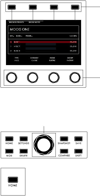
CENTER CONSOLE
The upper portion of the Center Console is built around an interactive graphic interface that provides access to a secondary layer of sound design parameters, as well as other Moog One Global parameters. The Center Console Display is operated via four Soft Buttons and four Soft Knobs, all of whose functions change based on the current screen.
Soft Buttons
Soft Knobs
Additionally, there is a large Master Encoder that can be used to scroll through lists and make selections by pushing down on the knob momentarily. In general, parameters are displayed above their respective Soft Knobs in groups of four. Here, values can be edited using the four Soft Knobs. If more than four parameters are available, rotating the Master Encoder will call up the additional rows. Together, the Soft Buttons, Soft Knobs, and Master Encoder provide effortless navigation of the graphic interface.
Master Encoder
Surrounding the Master Encoder are eight dedicated buttons.
HOME
Pressing the HOME button calls up the HOME screen, which displays the name of the active Preset, the names of the Timbres within the Preset, the respective keyboard ranges and On/Off status of Synth 1, 2, and 3, and the current Master Clock tempo.
12
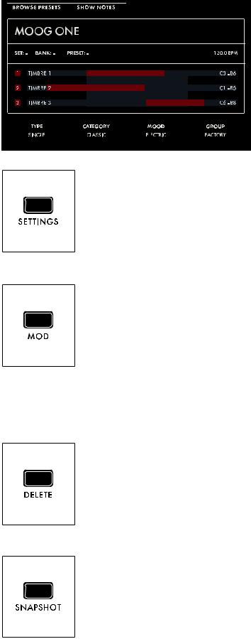
As notes are played on the keyboard, key range indicators will flash to show which Synth(s) are being played from those keys. In addition, the HOME screen shows any tags that have been assigned
(Type, Category, Mood, Group) to make the Preset more discoverable in a search.
NOTE: Pressing the HOME button will exit any currently selected screen and return to the HOME screen.
SETTINGS
This button provides access to all Moog One Global, Library, and Tuning parameters.
MOD
The MOD button opens the Modulation Matrix screen, where any possible modulation source can be freely routed to any possible modulation destination, and in any amount. A controller, such as the MOD wheel, may also be assigned in order to add articulation and expression to a modulation assignment. Additionally, Transforms can be inserted to place high and low limits on the modulation source signal, or to square or cube the modulation source control signal to further expand the variation and expressivity of the Moog One’s powerful modulation engine.
NOTE: When editing or creating a Modulation Matrix, pressing down on the Master Encoder will toggle back and forth between two sets of parameters (upper and lower) available for each modulation routing.
DELETE
The DELETE button is used to remove a modulation routing row, eliminate sequence data, and more. Its specific function is contextual, and is determined by the currently selected screen and parameter.
SNAPSHOT
Pressing SNAPSHOT performs a “micro-save” of the current data as you are editing. Each Snapshot is time stamped, so there is no need to keep saving the data manually under a new Preset name while you are editing. Any Snapshot can be recalled, auditioned, or designated as the “official” version of a Preset when you are saving the data. To view the Snapshots saved with the current Preset, Hold the SHIFT and SNAPSHOT buttons on the Front Panel.
13
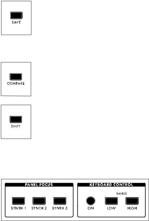
SAVE
The SAVE button begins the Save process that allows you to store the current settings of the instrument as a Preset. During the Save process, you will also have the ability to add names to the individual Timbres (1, 2, and 3) that are contained within the Preset.
NOTE: A full explanation of the save process can be found in the “Saving A
Preset” section on page 118.
NOTE: The SAVE button will light dimly if any parameters have been altered from their originally saved value, reminding you to save your changes if you wish to make them permanent.
COMPARE
Pressing the COMPARE button places a copied version of the current Preset parameter settings in a separate buffer, so you can tweak one version of a Preset and always compare it to the saved version as you edit.
NOTE: Pressing SHIFT and COMPARE simultaneously (SHIFT + COMPARE) creates a new initialized Preset using the Moog One default sound parameters and settings.
SHIFT
The SHIFT button is most often used in conjunction with another controller or function. For example, holding the SHIFT button while operating a Soft Knob parameter allows the value to be edited at a finer level of resolution. SHIFT operations can be performed by holding down the SHIFT button as you operate the controls. Alternatively, you can enter SHIFT mode by pressing and releasing the SHIFT button. The button will blink, and any operation performed will behave as if the SHIFT button is being held. Moog One will remain in this state until the SHIFT button is pressed again, and the blinking has stopped.
WORKING WITH SYNTHS
Tweaking knobs and pressing buttons has a direct effect on the sound of Moog One. But what exactly is the Front Panel controlling? Remember, a Preset is comprised of up to three Synths -- and one Synth
(or more) is always assigned to the Front Panel.
The active Synth is selected using the SYNTH 1, 2 and 3 buttons in the Panel Focus module, which allows the Front Panel knobs and buttons to only affect the currently selected Synth(s). Pressing any
SYNTH button by itself will select just that one Synth. Holding one SYNTH button while pressing additional SYNTH buttons will select multiple Synths, and allow any tweaks or edits to be applied to all of the selected Synths simultaneously.
NOTE: When multiple Synths are selected, the MORE pages and the sound engine status LEDs in the
LFO, Sequencer, and Arpeggiator modules will reflect the status of the most recently selected Synth. This SYNTH button will be illuminated at full brightness, while the initially held SYNTH buttons will be lit at a lesser brightness.
14

WORKING WITH SYNTHS (Continued)
The active Synth can be turned On or Off using the ON button located in the Keyboard Control module. In addition, each Synth can be quickly zone-limited to a specific area of the keyboard. To do this, press the LOW RANGE button (the LED will light) and then press a key on the keyboard to set the lowest playable note for the selected Synth (the LED goes dark). Next press the HIGH RANGE button (the LED will light) and press a key on the keyboard to set the highest playable note for the selected Synth (the LED goes dark). Additional visual confirmation is provided on the HOME page, where the keyboard range for each Synth is shown in red if Keyboard Control is ON, and greyed-out if it is Off.
TIP: Pressing both the LOW RANGE button and the HIGH RANGE button at the same time will expand the zone of the active Synth to its full note range of G0 to C10 (MIDI Note 0 - 127).
ADDING EXPRESSION
The Expression Assign buttons provide a convenient way to instantly assign a controller as a modulation source to a specific parameter. Simply press any Controller button in the Expression Assign module, and then tweak a knob or press a button to link the selected controller to that parameter. Once a modulation path has been created, the Quick Assign modulation screen will appear in the Center Console Display. Additional parameters may be accessed here.
The available controllers are:
•MW (Mod Wheel)
•PAD X (Pad Position X Axis - horizontal motion)
•PAD Y (Pad Position Y Axis - vertical motion)
•KB (Keyboard Note Value)
•VEL (Keyboard Velocity)
•AT (Aftertouch)
•EXP 1 (Expression Pedal input 1)
SELECTING A PRESET
Moog One can store a nearly infinite number of Presets that may be searched and filtered in a variety of ways. From the HOME screen, press the BROWSE PRESETS Soft Button at the upper left of LCD to open the Preset Browser.
15
SELECTING A PRESET (Continued)
Use the Master Encoder to scroll through the list of available Presets that are displayed on the left pane. Pressing down on the Master Encoder will load the selected Preset; you can also use the LOAD PRESET Soft Button at the top of the screen.
The upper-right pane lists the Timbres used to create this Preset. The lower-right pane lists any tags that have been assigned to this Preset. Tags narrow the list of available selections, making it easier to find a specific or appropriate Preset.
The four Soft Knobs at the bottom of the screen can choose which Presets will be displayed according to TYPE, CATEGORY, MOOD, and GROUP. All tags are user definable, with the exception of TYPE. Only TYPE has fixed options - SINGLE, LAYER, SPLIT, and MULTI. Generally, one would use SINGLE for a Preset using a single Synth. SPLIT for multiple Synths playing in different areas of the keyboard,
LAYER for multiple Synths stacked on the same keys, and MULTI for a Preset combing SPLITS and LAYERS, etc.
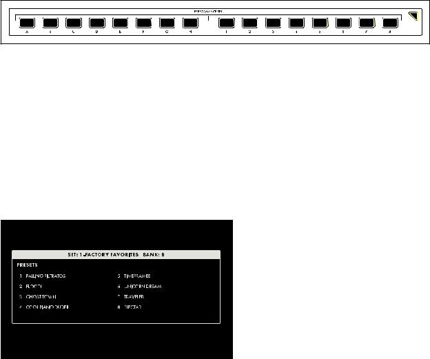
Presets in Moog One can also be instantly recalled using Performance Sets; the current Performance Set is always accessible from the lower Right Panel. Each Performance Set can recall up to 64 Presets, that are arranged in eight Banks (A - H) of eight Presets (1 - 8). Performance Sets allow you to have select Presets ready and on tap for instant access during a live performance - or even a studio session.
To assign the active Preset to the currently loaded Performance Set, simply press the Bank (A - H) button of your choice, then press and hold the desired Preset (1 - 9) button for 1 second. The Preset button will blink rapidly to let you know your Preset is now assigned to that location.
NOTE: The Performance Set does not itself provide storage of Presets; instead, the Performance Set saves “pointers” that direct Moog One to recall a specific Preset from its memory banks.
To select a Preset from a Performance Set, simply press a Bank button (A - H), and then press a Preset button (1 - 9) to choose a Preset from your selected Bank.
NOTE: Buttons that are dimly lit indicate that there’s a Preset assigned to that button. Buttons that are completely dark indicate that no Preset has been assigned.
TIP: There is a SHOW BANK PREVIEW option available (under SETTINGS - GLOBAL - HARDWARE SETTINGS). When this function is On, pressing a Bank button will open a screen showing all of the Presets assigned to that Bank.
16
KEYBOARD
Moog One features a premium quality, 61-note keyboard with velocity sensitivity and aftertouch, which are both available as modulation sources. Selectable sensitivity curves are also available to further tailor the keyboard’s response to your personal playing style.
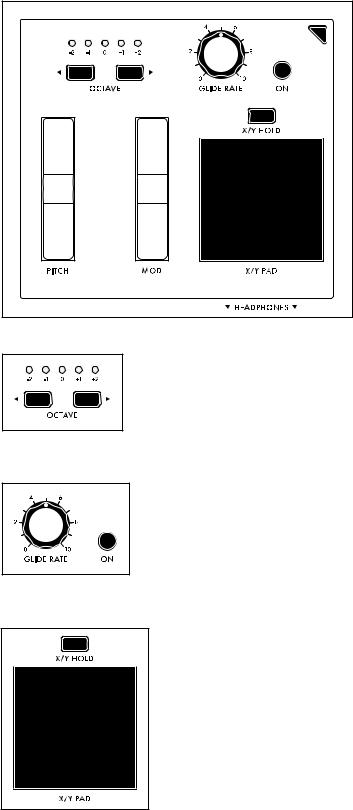
LEFT HAND CONTROLLER
Located at the left end of the Moog One keyboard, the Left Hand
Controller (LHC) provides a number of tools that enhance the playability, performance, and expression of this powerful instrument.
OCTAVE
The OCTAVE
 buttons allow the keyboard to be shifted up or down by octave. Pressing both OCTAVE buttons at the same time will reset the keyboard to its Default Octave.
NOTE: Press and hold both OCTAVE buttons to send a MIDI Panic (All Notes and Controllers Off) message.
GLIDE
Glide delivers a smooth, continuous change in pitch when moving from one note to the next. In addition to the GLIDE RATE knob and the GLIDE ON button, Moog One offers three types of Glide, as well as additional parameters for Legato, Glissando, and Gated Glide. Pressing the MORE button on the Left Hand Controller brings these parameters into view in the Center Console Display.
X/Y PAD
The X/Y PAD is a highly expressive, multidimensional touch surface whose X and Y axes can be easily assigned to a variety of musically useful destinations. There is also a third assignable axis that can sense Pressure on the surface of the pad. The X/Y PAD can operate in either a latching or non-latching manner as determined by the state of the X/Y HOLD button. If the X/Y HOLD button is illuminated, the held value of the X/Y PAD
can be saved as part of a Preset, similar to the MOD wheel amount. Pad pressure also sends a Gate On signal, available as a Control Source in the Mod Matrix.
17
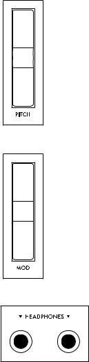
PITCH
The spring-loaded PITCH wheel is used to bend the pitch of the Moog One Oscillators up or down by a predetermined amount. The Pitch Bend Up and Pitch Bend Down range can easily be specified by pressing the MORE button on the Left Hand Controller and adjusting each parameter accordingly.
MOD
The MOD wheel is an assignable Controller that is most commonly used to manually determine the amount of modulation being applied from a Source to a Destination. In the case of the Moog One, the MOD wheel can also be assigned to multiple locations simultaneously through the Mod Matrix and EXPRESSION ASSIGN Buttons.
NOTE: The MOD wheel position can be saved as part of the Preset.
HEADPHONES
Located just below the X/Y PAD is a pair of front-facing stereo headphone outputs. Use the HEADPHONES knob in the Output module to set the volume level for both headphone outputs.
18

REAR PANEL
The Moog One Rear panel is equipped with a full complement of audio jacks, communication ports, MIDI connectors, and pedal ports – plus configurable CV In and CV Out connections – to accommodate nearly any use.
POWER
Moog One uses an external power supply/adapter that connects using a locking multi-pin cable. Orient the cable correctly and slide it straight in until it locks. To remove the cable, depress the locking tab on the connector plug and slide the cable straight out. Hold the cable by the locking plug -- never pull on the cable directly. The Moog One On/Off switch is located adjacent to the power port.
MAIN OUT/SUB OUT
Moog One features two sets of stereo outputs, the MAIN L (Left) and MAIN R (Right), and the SUB L (Left) and SUB R (Right). Both the
MAIN OUTS and the SUB OUTS feature 1/4” balanced TRS jacks. Each Synth can be assigned to either set of outputs – or both.
NOTE: The SUB OUTS do not carry the MASTER EFFECT signal and their volumes are not affected by the MASTER VOLUME knob.
INSERT 1 2 3 4
Four INSERT jacks are provided. Their routing is controlled by
pressing the Output Module MORE button. The tip of this tip-ring-
sleeve jack is wired as the Send, so each INSERT jack can be used
as an individual output when used with a standard unbalanced TS 1/4” cable. Each Insert jack can also be used with a Y-configuration insert
cable to achieve true insert functionality. The signal is returned to Moog One via the ring connection of the tip-ring-sleeve jack. This allows the active Synth to be sent to, and returned from, an external processor, while still maintaining its place in the internal mix. In addition, the ring/return connectors on adjacent pairs of inserts (1 & 2, 3 & 4) are stereo normalled, so that they can be used as stereo returns.
The way this works is that if nothing is connected to the return of Insert 2, the signal returning via Insert 1 will be summed to both the MAIN L and MAIN R outputs. Similarly, if nothing is connected to the return of Insert 4, the signal returning via Insert 3 will be summed to both the MAIN L and MAIN R outputs.
19

REAR PANEL (Continued)
EXT INPUT
Moog One provides an External Audio Input featuring a Neutrik connector, capable of
accepting either a balanced XLR cable, a balanced 1/4” TRS cable, or an unbalanced 1/4” TS cable.
The TRIM knob can adjust the input gain from -9 dB to +65 dB. There is also a Line Level (LINE)
input equipped with a 1/4” balanced TRS jack that can accept a balanced 1/4” TRS cable, or an unbalanced 1/4” TS cable. These external inputs
show up in the Moog One Mixer MORE screen as an additional sound source with a dedicated channel, although dedicated controls do not exist on the hardware Front Panel. From the Output module’s MORE page, the LINE Input can be routed to the Insert 3 buss, and the XLR/1/4” combo jack can be routed to Insert 4.
CV (CONTROL VOLTAGE) I/O
A control voltage is an analog control signal that allows the parameters and functions on one instrument to interact with the parameters and functions of another instrument in the analog domain. In the days before MIDI and USB, control voltage was the primary method for interconnection between synthesizers, and it is still the primary method of interfacing with modular and Eurorack synthesizers today.
Moog One is equipped with two dedicated CV IN jacks (1, 2) and four CV OUT jacks (1, 2, 3, 4). Additionally, both expression pedal inputs (EXP 1, EXP 2) and the SUSTAIN pedal input may also be configured for use as control voltage inputs for further analog control.
MIDI (5-PIN DIN)
Moog One offers 5-pin DIN MIDI IN, MIDI THRU, and MIDI OUT jacks to connect directly to other MIDI devices, such as sequencers, drum machines, interfaces, etc. Each Synth in a Preset can operate on a separate MIDI Channel for multitimbral control via external MIDI devices. In addition to note data, the MIDI ports can be configured to respond to MIDI Clock, controllers, expression, SysEx, and more.
20
REAR PANEL (Continued)
COMM (COMMUNICATION PORTS)
The LAN port enables Moog One to connect
directly to a computer network using a CAT-5
cable, which allows for remote servicing and future expansion. The USB HOST port provides a convenient way to backup instrument data onto portable USB drives for safe keeping and
backline applications. Additionally, the USB HOST port can also incorporate any classcompliant MIDI device (one that requires no
additional software drivers) into Moog One operations. The USB port found here allows Moog One to communicate directly with your computer via USB, sending and receiving MIDI and other system data.
PEDAL JACKS
Moog One includes three pedal input jacks. One is configured as a sustain (SUSTAIN) pedal input, and the other two as expression (EXP 1, EXP 2) pedal inputs. These inputs can be used to control nearly any Moog One parameter, allowing for a tremendously expressive performance.
NOTE: Keep in mind that these pedal jacks can also be used to receive CV signals (via 1/4” TS cables) from other synth modules, Eurorack systems, etc.
21
OSCILLATORS
Oscillators are the primary sound source for any synthesizer. Moog One Oscillators have no physical moving parts like a guitar’s string or a clarinet’s reed. Instead, the Oscillators generate an electronic signal that changes direction very rapidly. The patterns created by these fluctuations determine the waveform, or wave shape, which in turn determines the harmonic content of the signal. Moog One features three independent Oscillators that are nearly identical in design.
Each Oscillator generates two waveforms simultaneously; these can be blended via a dedicated
MIX control into a single complex, composite wave. For the first waveform, either a Triangle or
Sawtooth wave can be chosen. Applying the WAVE ANGLE control to the Triangle wave can change the symmetry of the waveform, allowing the Triangle to reach a Ramp or Sawtooth shape at either extreme. Applying the WAVE ANGLE control to the Sawtooth wave can vary the reset time, delivering increased harmonic diversity. The second waveform is a Pulse wave with a variable Pulse Width. As with the PULSE WIDTH knob, the TRI/SAW WAVE ANGLE knob can be modulated from another controller or parameter.
Together, their combined signals can be used to create an endless array of wave shapes that determine each Oscillator’s final sonic output. The OLED screen in the center of each Moog One Oscillator provides a static image of this composite waveform.
NOTE: The static image displayed on the OLED is created by the Oscillator’s parameter settings only, and does not reflect any real-time modulation routings that may also be affecting the final waveform.
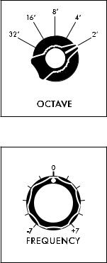
OCTAVE (32’, 16’, 8’, 4’, 2’)
Rotating the OCTAVE knob will change the pitch of the Oscillator by octaves. The historical “foot” settings are a musical convention that relates to pipe lengths on a pipe organ. The 8’ setting is considered standard, and will pitch the “C” in the middle of the Moog One keyboard (MIDI Note #60) at “Middle C.”
FREQUENCY (-7 to 0 to +7)
While the OCTAVE knob sets the Oscillator pitch in octave units, the FREQUENCY knob continuously varies the Oscillator pitch over a range of +/- 7 semitones (up or down a perfect fifth).
22
OSCILLATORS (Continued)
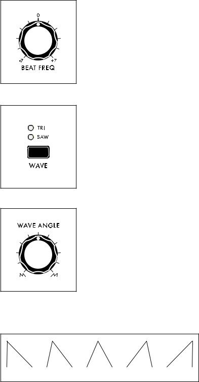
BEAT FREQ (-7 to 0 to +7)
Slightly detuning multiple Oscillators is a classic method for creating huge analog sounds. Moog One adds a Beat Frequency control that can offset the pitch of any Oscillator by a constant amount, which is measured in Hertz (Hz). Use the BEAT FREQ knob to create a slight tuning offset per Oscillator. This method provides consistent, musical results over the entire keyboard.
WAVE (TRI, SAW)
The WAVE button is used to select either the TRI (Triangle wave) or
SAW (Sawtooth) mode for the first wave generator.
WAVE ANGLE
The function of the WAVE ANGLE knob is determined by the
WAVE button selection.
TRI (TRIANGLE MODE)
With the WAVE button set to TRI (the TRI LED will be lit), rotating the
WAVE ANGLE knob will continually vary the wave shape, changing the relationship between the rising and falling segments of the wave.
The center position will create a Triangle wave. Rotating the knob to the far left will produce a wave shape closer to a Sawtooth wave; rotating the knob to the far right will produce a Reverse Sawtooth (or Ramp) wave.
NOTE: In TRI mode, the rising and falling phases of the wave both scale with pitch -- both get faster at higher pitches, and both get slower at lower pitches.
SAW |
TRIANGLE |
RAMP |
TIP: In TRI mode, try modulating the WAVE ANGLE to vary the rise and fall segments of the wave, producing a wide variety of timbres traditionally unavailable on an analog synthesizer.
23
OSCILLATORS (Continued)
SAW (SAWTOOTH MODE)
With the WAVE button set to SAW (the SAW LED will
be lit), rotating the WAVE ANGLE knob will continuously
vary the reset time of the Sawtooth wave. Rotating the knob hard left will produce a classic Moog Sawtooth
wave with a 6µs (microsecond) reset time. As the WAVE ANGLE knob is rotated to the right, the reset time of the
Sawtooth wave is increased, creating a darker and less aggressive timbre. The Wave Angle range is from 6µs to 1 ms.
NOTE: In SAW mode, modulating the Wave Angle will vary the reset time of the wave, resulting in dynamic variations of timbral complexity.
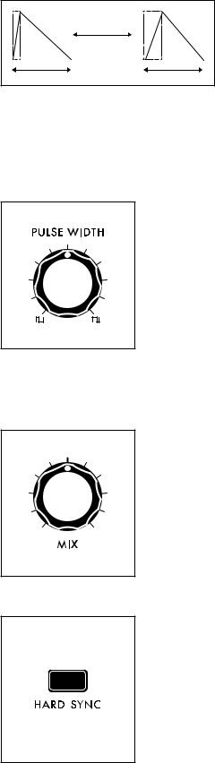
PULSE WIDTH
The second wave generator in each Oscillator creates a pulse wave. Rotating the PULSE WIDTH knob will vary the duty-cycle (Pulse Width) of the wave. Rotating the PULSE WIDTH knob to the far left will create a narrow pulse with a short duty cycle; the center position will produce a square wave (50% duty cycle); rotating the knob to the far right will produce a wide pulse with a long duty cycle.
NOTE: The inverse of a narrow Pulse Wave with a 20% “on” time is a wide
Pulse Wave with a 20% “off” time. Graphically, they are mirror images of each other, and their harmonic contents are identical. However, it is the smooth cyclic transition from one to the other that gives Pulse Width Modulation (PWM) its distinctive sound.
MIX
Using the MIX knob, you can create a unique and intricate analog wave shape by combining the outputs of the Triangle/Sawtooth generator and the Pulse/Square generator. The MIX knob determines the blend between the two, and the resultant waveform is shown in the individual OLED window for each Oscillator. Rotating the MIX knob to the far left outputs the Triangle/Sawtooth only; the center position provides an equal mix of the two generators; rotating the MIX knob to the far right will output the Pulse/Square only.
HARD SYNC (OSCILLATOR 2 and OSCILLATOR 3 only)
When an Oscillator is sync’d to the phase of another Oscillator, the sync’d Oscillator is being forced to reset itself to match every waveform peak of the master Oscillator. As the sync’d Oscillator struggles to keep up, the resulting wave shape can become more and more complex.
24
OSCILLATORS (Continued)
OSCILLATOR 1
HARD SYNC’D OSCILLATOR
The sound can become aggressive, metallic, or even exhibit elements of comb filtering. Adding modulation to the frequency of a sync’d Oscillator can greatly enhance this effect. Moog One sets Oscillator 1 as the Master Oscillator by default. Use the HARD SYNC button to force the selected Oscillator(s) to sync to
Oscillator 1.
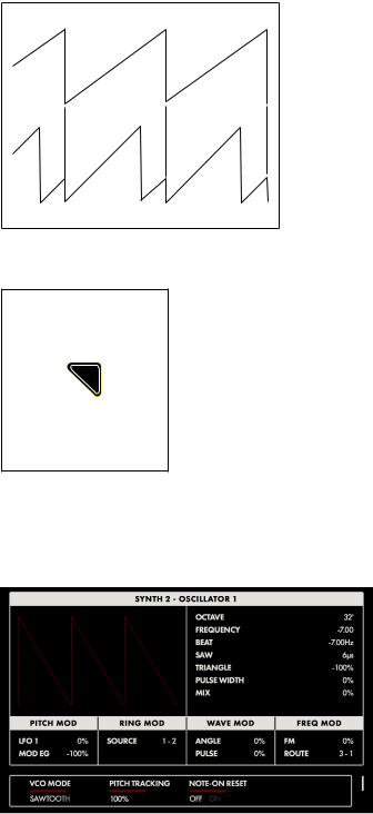
OSCILLATOR MORE PAGE
Pressing the triangular MORE button in the upper right corner of any Oscillator module will reveal a second level of parameters that can be accessed and modified using the Soft Knobs and Master Encoder in the Center Console. These additional parameters are displayed
in the bottom portion of the screen. The left pane shows a static representation of the final wave shape output from the Oscillator.
NOTE: The static image displayed on the screen is created by the
Oscillator’s parameter settings only, and does not reflect any real-time modulation routings that may also be affecting the final waveform.
The right pane shows the current value of the Front Panel hardware parameters for this module.
NOTE: Pressing the (now) illuminated MORE button will exit the MORE page and recall the HOME screen.
CHANGING THE VALUE
Rotate the Soft Knob below each parameter name to change its value. In some cases, the Soft Knob simply turns a function on or off. In other cases, the Soft Knob may choose from a range of values or settings.
SELECTING A ROW
The scroll bar at the right edge of the screen indicates the current row. Rotating the Master Encoder to the right will select the next available row of parameters.
Rotating the Master Encoder to the left will select the previous row. Once selected, rotate the Soft Knob below each parameter name to change its value.
25
OSCILLATORS (Continued)
VCO MODE (SAWTOOTH, TRIANGLE)
This parameter shows the status of the WAVE button on the front panel. This function can also be controlled here.
PITCH TRACKING (0 to 200%)
With this parameter set to 100%, the pitch of the Oscillator will track the keyboard as normal. In some cases you may want to change this value. For example, at 0%, the Oscillator would play the same pitch, regardless of the note played. Another example would be to set an Oscillator to Hard Sync, and utilize an excessive value (150% - 200%) to enhance the effect.
NOTE-ON RESET (OFF, ON)
Normally, an Oscillator is constantly running, and each new note played begins from the current point in the waveform cycle. When NOTE-ON RESET is On, the phase of the Oscillator is reset to zero with each new note-on command, which can make for extremely punchy bass sounds.
BEND OFFSET
The Bend Offset amount is set individually for each oscillator, and is combined with the per-Synth Pitch Bend Up and Down values set on the LHC MORE Page. Bend Offset provides separate values for Bend Up and Bend Down, and each can be set to either a positive or a negative value. In this way, the
Pitch Bend wheel can be used to resolve each oscillator to a specific note or interval at either end of its travel, allowing for creative harmonies and chords to be introduced as part of a performance.
BEND UP OFFSET (-24 to 0 to +24)
This parameter specifies the amount of Pitch Bend Offset applied to the Oscillator when the Pitch Bend wheel is moved Up. When the value is set to zero no offset is added. Negative offset values will bend the pitch down; positive values will bend the pitch up. The range is +/-
24 semitones (two octaves).
BEND DOWN OFFSET (-24 to 0 to +24)
This parameter specifies the amount of Pitch Bend Offset applied to the Oscillator when the Pitch Bend wheel is moved Down. When the value is set to zero no offset is added. Negative offset values will bend the pitch down; positive values will bend the pitch up. The range is +/-
24 semitones (two octaves).
HARD SYNC SRC. (Oscillator 2 and Oscillator 3 only)
The default source for Hard Sync on Oscillator 2 and Oscillator 3 is Oscillator 1. Here, a different oscillator can be designated as the Hard Sync source.
OSCILLATOR 2 (VCO 1, VCO 3)
OSCILLATOR 3 (VCO 1, VCO 2)
26
OSCILLATOR COMMON PARAMETERS
Just below the Oscillator section is a set of controls that affect all three of the oscillators in the active Synth. These parameters are instantly available and are conveniently hard-wired to commonly-used modulation applications.
PITCH MODULATION
These modulation parameters affect the pitch of all three oscillators.
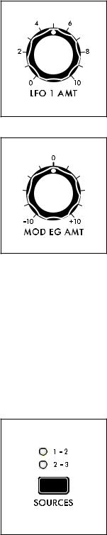
LFO 1 AMT (0 to 10)
Turning this knob will determine the amount of LFO 1 being applied as a modulation source to the pitch of all three Oscillators. The higher the value of this knob, the deeper the modulation effect.
MOD EG AMT (-10 to 0 to +10)
Adjusting this knob will determine how much of the control signal from the Modulation Envelope Generator is being applied as a modulation source to the pitch of all three Oscillators. The center position equals zero and produces no effect. Rotating the knob to the right increases the amount of MOD EG signal; rotating the knob to the left inverts the amount of MOD EG signal.
RING MOD (RING MODULATOR)
Ring Modulation analyzes two input signals to create a new, complex output signal. Mathematically, this output signal is the combined sum and difference of the frequencies of the input signals. Ring Modulation is known for creating metallic, robotic and inharmonic sounds. The output of the RING MOD appears in a dedicated channel in the Moog One Mixer module.
NOTE: The oscillator signals being fed into the RING MOD are tapped directly from the Triangle/Sawtooth generator, and are not affected by the Oscillators’ PULSE WIDTH knobs or the Oscillator MIX knobs.
TIP: Try altering the PITCH TRACKING amount of one of the Oscillators (using the MORE button) to emphasize the RING MOD effect. You may want to reduce the volume of the altered Oscillator.
SOURCES (1 – 2, 2 – 3)
Use this button to choose which pair of Oscillators will be fed into the
RING MOD. The corresponding LED will light.
1 – 2
Oscillator 1 and Oscillator 2 will drive the Ring Modulator.
2 – 3
Oscillator 2 and Oscillator 3 will drive the Ring Modulator.
27
WAVEFORM MODULATION
These modulation parameters affect the waveform of the Oscillators. Both knobs are applying LFO 3 to the Oscillator wave shape.
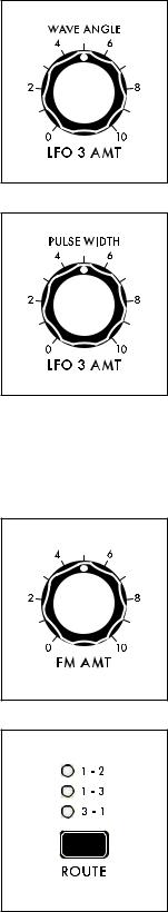
WAVE ANGLE / LFO 3 AMT (0 to 10)
Turning this knob determines the amount of LFO 3 that is applied as a modulation source to the Oscillators’ Wave Angle parameter. The higher the value of this knob, the deeper the effect.
PULSE WIDTH / LFO 3 AMT (0 to 10)
Turning this knob determines the amount of LFO 3 that is applied as a modulation source to the Oscillators’ Pulse Width parameter. The higher the value of this knob, the deeper the effect.
FM (FREQUENCY MODULATION)
Frequency Modulation (FM) allows the output of one oscillator to modulate the frequency of another oscillator. Applying FM can produce complex sounds and introduce interesting harmonics. Moog One uses linear FM.
FM AMT (0 to 10)
Turning this knob determines the amount of Frequency Modulation that is applied from one Oscillator to another. The higher the value of this knob, the deeper the effect.
ROUTE (1 – 2, 1 – 3, 3 – 1)
This button selects the Oscillators and routing scheme for the FM effect.
When making a selection, the corresponding LED will light.
1 – 2
The output of Oscillator 1 is modulating the frequency of Oscillator 2.
1 – 3
The output of Oscillator 1 is modulating the frequency of Oscillator 3.
3 – 1
The output of Oscillator 3 is modulating the frequency of Oscillator 1.
28

NOISE
In addition to the three Oscillators and the Ring Modulator, Moog One also includes a sophisticated dual source Noise Generator, available as a separate audio source with a dedicated channel in the Mixer module.
Built into the Noise module is a dedicated Envelope Generator to provide independent articulation of the noise. This envelope generator offers a variable ATTACK knob, a variable RELEASE knob, and a SUSTAIN button that allows the Noise generator to continue to sound as long as a note is held.
ATTACK (1 M-SEC to 10 SEC)
The ATTACK knob sets the Attack Time of the Noise Envelope Generator, controlling how fast the Noise reaches its maximum volume once a key has been pressed or a gate signal received.
RELEASE (1 M-SEC TO 10 SEC)
The RELEASE knob sets the Release Time of the Noise Envelope Generator, controlling how slowly the NOISE fades out after a key is released or the gate is closed.
SUSTAIN (ON/LIT, OFF/UNLIT)
When the SUSTAIN button is engaged, the Noise Generator will continue to sound as long as a gate is held open, either by pressing the Keyboard, holding a Sustain Pedal, or when receiving a CV Gate. When the SUSTAIN button is off, the Release stage will act as more of a Decay stage, fading the sound down as soon as the Attack stage has been completed.
29
NOISE (Continued)
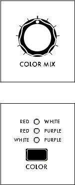
The Noise generator produces three different colors of noise – White, Red, and Purple. Any two noise colors can be selected at once using the COLOR button; the COLOR MIX knob creates a blend between those two noise colors.
WHITE NOISE
COLOR MIX
The COLOR MIX knob sets the balance between the two colors of noise selected by the COLOR button. Rotating the knob fully to the left will emphasize the color listed in the left column. Rotating the knob fully to the right will emphasize the color listed in the right column. Placing the knob in the center position will provide an even mix between the two.
COLOR
The COLOR button specifies which two colors of noise are being blended using the COLOR MIX knob - the corresponding LED will light for each selected pair.
RED + WHITE
Red Noise and White Noise are selected.
RED + PURPLE
Red Noise and Purple Noise are selected.
WHITE + PURPLE
White Noise and Purple Noise are selected.
White Noise is analogous to white light; it contains the same amount of energy across every octave band in the audio spectrum. It’s the sound you hear when an old television is set to a non-existing channel.
RED NOISE
Also referred to as Brownian Noise, Red Noise provides a 6 dB decrease in energy per octave across the audio spectrum as the frequency increases. This greatly curtails the high-frequency Noise components. Red Noise can be thought of as a “rumble” type of Noise.
PURPLE NOISE
Sometimes called Violet Noise, Purple Noise is the counterpart to Red Noise. Purple Noise provides a 6 dB increase in energy per octave across the audio spectrum as the frequency increases. This greatly
reduces the low-frequency Noise components. Purple Noise can be thought of as a “hiss” type of Noise.
NOTE: Pink Noise – a popular element in modular and percussion synthesis – can be approximated by using the COLOR button to select RED + WHITE, and by then adjusting the COLOR MIX knob to taste.
30
 Loading...