


3
IMPORTANT SAFETY INSTRUCTIONS
WARNING - WHEN USING ELECTRIC PRODUCTS, THESE BASIC PRECAUTIONS SHOULD ALWAYS BE FOLLOWED:
1.Read all the instructions before using the product.
2.Do not use this product near water - for example, near a bathtub, washbowl, kitchen sink, in a wet basement, or near a swimming pool or the like.
3.This product, in combination with an amplifier and headphones or speakers, may be capable of producing sound levels that could cause permanent hearing loss. Do not operate for a long period of time at a high volume level or at a level that is uncomfortable.
4.The product should be located so that its location does not interfere with its proper ventilation.
5.The product should be located away from heat sources such as radiators, heat registers, or other products that produce heat. No naked flame sources (such as candles, lighters, etc.) should be placed near this product. Do not operate in direct sunlight.
6.The product should be connected to a power supply only of the type described in the operating instructions or as marked on the product.
7.The power supply cord of the product should be unplugged from the outlet when left unused for a long period of time or during lightning storms.
8.Care should be taken so that objects do not fall, and liquids are not spilled, into the enclosure through openings.
There are no user serviceable parts inside. Refer all servicing to qualified personnel only.
NOTE: This equipment has been tested and found to comply with the limits for a Class B digital device, pursuant to Part 15 of the FCC rules. These limits are designed to provide reasonable protection against harmful interference in a residential installation. This equipment generates, uses, and can radiate radio frequency energy and, if not installed and used in accordance with the instructions, may cause harmful interference to radio communications. However, there is no guarantee that interference will not occur in a particular installation. If this equipment does cause harmful interference to radio
or television reception, which can be determined by turning the equipment off and on, the user is encouraged to try to correct the interference by one or more of the following measures:
—Reorient or relocate the receiving antenna.
—Increase the separation between the equipment and receiver.
—Connect the equipment to an outlet on a circuit different from that to which the receiver is connected.
—Consult the dealer or an experienced radio/TV technician for help.
CAUTION: Please note that any changes or modifications made to this product not expressly approved by Moog Music Inc. could void the user’s authority granted by the FCC to operate the equipment.
TABLE OF CONTENTS
8UNPACKING & INSPECTION
8SETUP & CONNECTIONS
9 |
ABOUT MATRIARCH |
10 |
SIGNAL FLOW |
10 |
FEATURES & CONTROLS |
10 |
KEYBOARD |
1 1 |
LEFT-HAND CONTROLLER |
13OSCILLATORS
14UNDERSTANDING OSCILLATOR SYNC
16OSCILLATOR PATCH POINTS
17MIXER
19MIXER PATCH POINTS
20 FILTERS
23 FILTER PATCH POINTS
25 ENVELOPE GENERATORS (ADSR)
27 ENVELOPE GENERATOR PATCH POINTS
29OUTPUT
30VCA PATCH POINTS
32STEREO DELAY
34STEREO DELAY PATCH POINTS
36MODULATION
38MODULATION PATCH POINTS
40UTILITIES (1)
42UTILITIES (2)
44ARP / SEQ
48ARP / SEQ PATCH POINTS
49ARP / SEQ LHC CONTROLS
50PARAPHONY
52 REAR PANEL
54 AUDIO JACKS
56 STEREO DELAY JACKS
56 KEYBOARD JACKS
58ARP / SEQ JACKS
59MIDI PORTS
61 GLOBAL SETTINGS
70 SIGNAL FLOW DIAGRAMS
74 BLANK PRESETS
78SPECIFICATIONS
79WARRANTY
79 SERVICE & SUPPORT INFORMATION

|
|
0 |
|
8’ |
4’ |
8’ |
4’ |
|
|
|
|
||||
|
- |
|
+ |
16’ |
2’ |
16’ |
|
|
|
|
|
|
|
||
2 |
3 |
|
|
|
|
|
|
1 |
4 |
|
|
|
- |
|
+ |
|
|
|
|
|
|
0
- |
+ |
8’ |
4’ |
8’ |
4’ |
16’ |
|
16’ |
|
- |
+ |
- |
+ |
|
|
|
0 |
200Hz |
2kHz |
- |
+ |
|
|
||
20Hz |
20kHz |
|
|
- |
+ |
- |
+ |
STEREO DELAY
- |
+ |
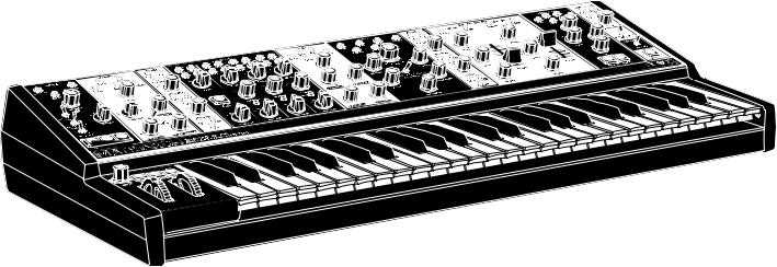
Based on the vintage circuitry of classic Moog synthesizer modules, Matriarch is a catalyst for creative ideas and a medium for multidimensional expression.
6 |
7 |
UNPACKING & INSPECTION
Check the contents of the shipping carton. Be careful when unpacking your new Moog Matriarch® so that nothing is lost or damaged. Moog recommends saving the carton and all packing materials in case you ever need to ship the instrument for any reason.
Matriarch ships with the following items:
1.Matriarch Semi-Modular Analog Synthesizer
2.Power Supply
3.Owner’s Manual
4.Patch Cables
5.Registration Card
What you will need:
1.A table or surface where you can set your Matriarch. (30lbs / 13.61kg)
2.A 1/4” instrument cable and amplified speaker, or headphones with a 1/4” plug.
3.A properly wired AC outlet. (100 Volts to 240 Volts AC; 50/60 Hz)
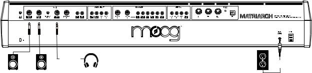
SETUP & CONNECTIONS
Speakers |
Headphones |
|
Power |
|
Supply |
POWER
Plug the included power adapter into the 12V DC power jack on the back of your Matriarch. Plug the other end of the included power adapter into an AC outlet. Matriarch uses a universal power supply that operates with power sources from 100 Volts to 240 Volts AC; 50/60 Hz.
NOTE: Your Matriarch is an analog instrument and should be allowed 10-15 minutes to warm up before use. In cases where it has been left in a cold car overnight, for example, it may take as long as 25 minutes before oscillator tuning has stabilized. Do not operate Matriarch in direct sunlight.
AUDIO OUTPUTS
With the Matriarch MAIN VOLUME knob turned all the way down, plug one end of a 1/4” (TS) instrument cable into the MAIN OUT LEFT (MONO) jack on the rear panel to monitor the instrument in mono. To monitor the instrument in stereo, connect a second 1/4” (TS) instrument cable to the MAIN OUT RIGHT jack on the rear panel.
NOTE: The MAIN OUT jacks will work with both TS and TRS 1/4” cables.
Plug the other end(s) into an amplified speaker or mixing console line-level input. Raise the MAIN VOLUME knob above the 12 O’clock position, and adjust the amplifier or mixer level accordingly.
HEADPHONE OUT
Also on the rear panel is a stereo headphone jack, complete with its own HEADPHONE VOLUME knob for private listening or monitoring.
NOTE: This headphone jack is unaffected by the MAIN VOLUME knob in the Output module on the front panel.
8
ABOUT MATRIARCH
Matriarch sits at the pinnacle of the Moog family of semi-modular synthesizers. The patchable architecture and classic Moog circuits reward open exploration with endless sonic possibilities and unparalleled analog sound. Matriarch’s four analog VCOs can be split into four notes of paraphony that can be sequenced, shifted, and stored with the instrument’s intuitive 256 step Sequencer, or stacked in unison to create a massive four-oscillator mono synth.
With a deep assortment of synthesis modules based on Bob Moog’s original circuit designs, Matriarch provides a 100% analog signal path spanning a dynamic sonic vocabulary – from overdriven monophonic bass to gently evolving paraphonic plucks that cycle through waveshapes into a wash of infinite delay trails. Coupling the power of vintage-designed stereo Ladder Filters, dual Envelope Generators, stereo Analog Delays, and stereo VCAs, Matriarch delivers a multi-dimensional sound that empowers the sonic exploration of both space and time.
Although Matriarch uses a semi-modular design that requires absolutely no patching, 90 modular patch points are easily accessible throughout the panel via the included 3.5mm patch cables. This powerful electronic instrument is a highly-versatile addition to any stage or studio that can effortlessly transform from a performance keyboard into a fully modular analog synthesizer at a moment’s notice.
In addition to its standalone function, Matriarch is also an ideal processor of external sound sources and a powerful keyboard front-end for expanding a DFAM, Mother-32, Grandmother, or Eurorack modular system.
MOD
EXQUISITE EXPRESSION OSCILLATOR ABUNDANCE MULTIPLE MODULATORS
49 velocity-sensing keys with aftertouch, glide, and pitch & mod wheels.
4 analog oscillators with Hard Sync and FM capabilities.
Dual, voltage-controlled analog LFOs with selectable waveforms and patchable routing.
|
FLEXIBLE FILTERING |
|
HANDS-ON INTERFACE |
Dual Ladder filters configurable |
ANALOG EFFECTS |
Color-coded semi-modular front |
in series, parallel, or stereo modes. |
Stereo analog delay with MIDI |
panel with single-function knobs, |
|
sync, ping pong, and tap tempo. |
switches, and buttons. |
RHYTHMIC RECALL |
|
|
Record and playback 12 unique |
USEFUL UTILITIES |
PATCHABLE PERFORMER |
sequences with up to 256 notes |
Three bipolar voltage-controlled |
90 modular patch points with |
each, or arpeggiate endlessly |
attenuators and two 4-jack mults. |
expression pedal connectivity, |
through a random selection of |
|
external audio input, plus 5-Pin |
held notes. |
VERSATILE VOICING |
DIN & USB MIDI. |
|
Perform in mono (1-note), 2-note, |
|
|
and 4-note paraphonic modes. |
9
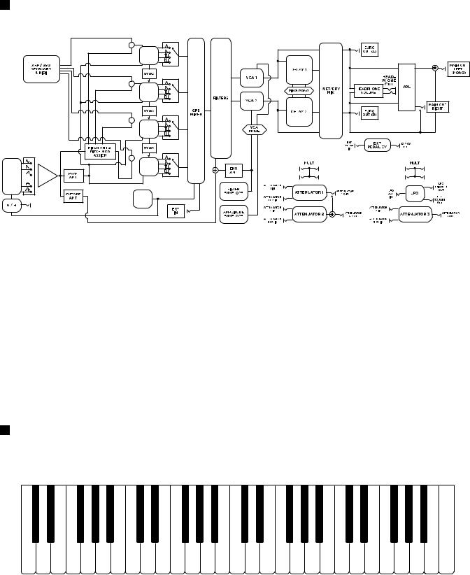
SIGNAL FLOW
MOD MOD 
 WHEEL OSC
  VCA
VCA
 PITCH
PITCH
OSC 1
PWM
 PITCH
PITCH
OSC 2
PWM
 PITCH
PITCH
OSC 3
PWM
 PITCH
PITCH
OSC 4
PWM
NOISE
REFERENCE: To view the full Signal Flow diagram see Page 70-71.
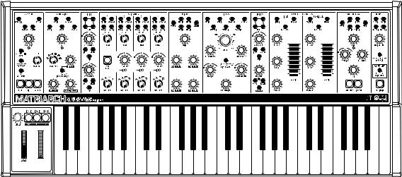
FEATURES & CONTROLS
Matriarch’s panel is comprised largely of single-function knobs, switches, and buttons that are grouped together by module. Each module is equipped with a set of 3.5mm patch points that can be utilized to create new audio and control pathways within Matriarch. These patch points can also be used to establish synchronization and interconnectivity with other Moog synthesizers like Mother-32, DFAM, and Grandmother, or to create a completely a new instrument through deep integration with a Eurorack modular system.
NOTE: Additional patch points and connectors are available on Matriarch’s rear panel.
KEYBOARD
Matriarch offers a 49-note Fatar keyboard with velocity and channel aftertouch. There are no hardwired connections for these signals; they can be easily accessed via rear-panel patch points and MIDI.
NOTE: By using the Mults and Attenuators found in the Utilities modules, multiple parameters can be affected – in varying amounts – using the Keyboard Pitch, Velocity and Aftertouch control signals.
10
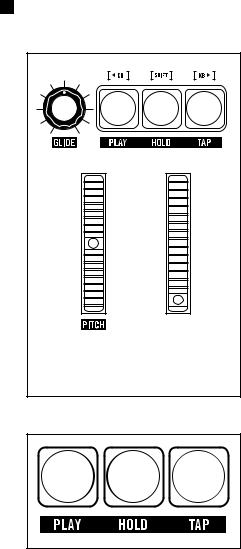
LEFT-HAND CONTROLLER
MOD |
The Left-Hand Controller (LHC) is home to a number of performance-enriching controls. The PITCH (Pitch Bend) and MOD (Modulation) wheels deliver real-time expression, while the GLIDE knob provides enhanced articulation between notes. The Left-Hand Controller is also home to the Transport Buttons for the Arpeggiator and Sequencer, allowing instant access to these powerful features during performance.
TRANSPORT BUTTONS
PLAY
The green PLAY button acts as a toggle, either arming or disarming the Arpeggiator or Sequencer. When this button is lit, pressing the notes to be arpeggiated, or the starting note of a sequence, will begin playback. This button will remain lit when the Sequencer or Arpeggiator is armed.
HOLD
The blue HOLD button acts as a latch for the Arpeggiator and the Sequencer, where notes played and released remain held until new notes are played. This button will remain lit as long as the Hold function is engaged.
TAP
The playback tempo of the Arpeggiator or Sequencer can be set using a series of successive taps on this yellow TAP button. Once a Tempo has been entered using the TAP button, it will remain lit yellow. To exit Tap Tempo, simply press and hold the TAP button until its light goes out.
TIP: As long as the TAP button is lit yellow (indicating a tempo has been entered using this method), turning the RATE knob in the ARP / SEQ module will select clock divisions of this tempo.
NOTE: More specific information regarding these buttons can be found in the ARP / SEQ chapter of this manual located on Page 49.
11
LEFT-HAND CONTROLLER (Continued)
MOD
OCTAVE TRANSPOSE
The Transport Buttons can also be used to shift the pitch of the keyboard up or down in one-octave increments. This allows the range of the keyboard to be extended without changing the settings of individual oscillators. To transpose the keyboard by octave units, simply press and hold the [SHIFT] button, and then press the [<KB] button (down one octave) or [KB>] button (up one octave). The transpose range is up or down two octaves.
NOTE: Press the HOLD, PLAY, and TAP buttons at the same time to reset Matriarch to its default octave. Press and hold these same three buttons for one second to utilize the MIDI Panic function and silence any stuck notes.
PITCH
The PITCH wheel (Pitch Bend) provides an intuitive method for quickly bending the pitch of the oscillators up or down during live performance.
NOTE: The PITCH wheel is spring-loaded and will return to center position as soon as it is released.
MOD
The MOD wheel (Modulation) provides an expressive way to introduce and control modulation while performing. At minimum position, no modulation is applied. As the MOD wheel’s position is raised, more modulation is introduced. At its uppermost position, the amount of modulation is equal to the maximum values set using the PITCH AMT (Oscillator Pitch), CUTOFF AMT (Filter Cutoff Frequency), and PULSE WIDTH AMT (Pulse Width Modulation [PWM]) knobs in the Modulation module.
NOTE: Unlike the PITCH wheel, the MOD wheel is not spring-loaded, and will remain in position until it is moved again.
TIP: You can patch from the MOD WHL OUT jack on the Matriarch rear panel to any available destination for a more expressive and expansive performance.
12
LEFT-HAND CONTROLLER (Continued)
GLIDE
Glide produces a smooth, continuous change in pitch when transitioning from one note to the next. The GLIDE knob sets the amount of time needed to complete this transition. When the GLIDE knob is set to minimum, there is no Glide effect. Raising the value of the GLIDE knob will increase the Glide time between notes from zero to a maximum value of roughly ten seconds.
TIP: Legato Glide only produces the Glide effect when a new note is played while the previous note is still held down on the keyboard. To turn Legato Glide On, continue to press the [SHIFT] button while turning the GLIDE knob to the right. To turn Legato Glide Off, continue to press the [SHIFT] button while turning the GLIDE knob to the left. The Default setting for Legato Glide is Off.
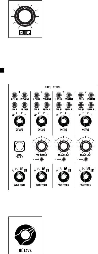
OSCILLATORS
Matriarch’s analog sound begins with four voltage-controlled oscillators (VCOs) of nearly identical design. Each oscillator provides individual control of the Octave and Waveform
settings, while Oscillators 2, 3, and 4 also feature a FREQUENCY knob used for detuning from Oscillator 1.
Oscillators can be tuned in unison or set to differing intervals, octaves, and waveforms to create a vast expanse of monophonic and paraphonic sounds.
Oscillators 2, 3, and 4 can also be Hard Sync’d to the previous oscillator using the dedicated SYNC buttons – Oscillator 2 can be sync’d to Oscillator 1, Oscillator 3 to Oscillator 2, and Oscillator 4 to Oscillator 3.
NOTE: There is a FINE TUNE knob located on Matriarch’s rear panel for adjusting the overall tuning of the instrument.
MODULE PROVENANCE: Matriarch’s Oscillators are based on those found in the Minimoog Voyager and are descendants of the classic Moog 921 Oscillator design.
8’ 4’ 16’ 2’
OCTAVE
This four-position switch is used to select the fundamental octave setting for each oscillator. The choices are 16’, 8’, 4’ and 2’.
NOTE: These octave numbers originated as lengths (or footages) in the days of pipe organs.
13
OSCILLATORS (Continued)
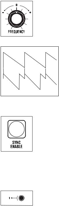
FREQUENCY (Oscillators 2, 3, & 4)
The FREQUENCY knob detunes each oscillator from the pitch of Oscillator 1 over a range of +/- 7 semitones (or a musical 5th). The center position (12 O’clock) tunes the oscillator in unison with Oscillator 1. Increasing the value (+) raises the pitch, while decreasing the value (–) lowers the pitch.
NOTE: The range of the FREQUENCY knobs can be specified in the Global Settings.
OSCILLATOR
UNDERSTANDING OSCILLATOR SYNC
When two oscillators are sync’d, the first oscillator behaves normally, while the phase of the second, or sync’d oscillator, is forced to reset its cycle to match each new cycle of the first oscillator. This synchronization causes the waveform of
the sync’d oscillator to take on a more complex wave shape as it works to stay aligned with the first oscillator. Sync is useful for creating sharp, metallic, and flange-like sounds, while also ensuring that the pitch of the sync’d oscillator stays locked
to the pitch of the first oscillator.
HARD SYNC’D OSCILLATOR
TIP: Applying modulation to the pitch of a sync’d oscillator is a great way to enhance the sound of the Sync effect.
SYNC ENABLE (Main)
Pressing the main red SYNC ENABLE button enables the Sync functions of Oscillator 2, Oscillator 3, and Oscillator 4. The button will remain lit as long as the Sync function is On. Press the red SYNC ENABLE button a second time to turn the Sync function Off.
NOTE: When the frequency of the sync’d oscillator is set below that of the oscillator it is sync’d to, the sync’d oscillator will not be able to complete a full cycle before it is forced to reset, resulting in little or no sound.
INDIVIDUAL OSCILLATOR SYNC (Oscillators 2, 3, & 4)
Oscillators 2, 3, and 4 are each equipped with a dedicated button that allows it to be sync’d to the previous oscillator.
1 2 SYNC
Pressing this button (On/lit red) will cause Oscillator 2 to become sync’d to Oscillator 1. In this case, changing the Frequency of Oscillator 2 will vary the degree of the Sync effect and its associated harmonic content. The range of the FREQUENCY knob is also greatly increased while the oscillator is sync’d.
14
OSCILLATORS (Continued)
2 3 SYNC
Pressing this button (On/lit red) will cause Oscillator 3 to become sync’d to Oscillator 2. In this case, changing the Frequency of Oscillator 3 will vary the degree of the Sync effect and its associated harmonic content. The range of the FREQUENCY knob is also greatly increased while the oscillator is sync’d.
3 4 SYNC
Pressing this button (On/lit red) will cause Oscillator 4 to become sync’d to Oscillator 3. In this case, changing the Frequency of Oscillator 4 will vary the degree of the Sync effect and its associated harmonic content. The range of the FREQUENCY knob is also greatly increased while the oscillator is sync’d.
NOTE: Remember, the main red SYNC button must be On (lit) for the individual
Oscillator Sync functions to work.
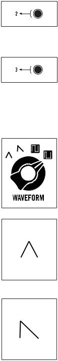
WAVEFORM (Triangle, Sawtooth, Square, Pulse)
Each waveform has unique harmonic content that is based on the number and strength of the harmonic overtones that it contains. These overtones are what impart a particular timbre, or character, to the sound of each oscillator. This four-position knob is used to select the oscillator’s waveform. The choices are Triangle, Sawtooth, Square, and Narrow Pulse.
TRIANGLE
The Triangle wave has an extremely strong fundamental, and contains only odd-numbered harmonics at very low levels. This makes the Triangle wave an ideal choice for creating soft, flute-like sounds that have a relatively pure tone with little overtone activity.
TIP: Try mixing a Triangle wave from one oscillator with a more complex wave from another to emphasize one particular harmonic without adding unwanted overtones.
SAWTOOTH
The Sawtooth wave is the most harmonically dense of the four waveform options, containing all of the natural harmonics in relatively strong levels. In addition to creating thick, brassy sounds, the Sawtooth wave lends itself to powerful lead and bass sounds as well.
PULSE WAVES (Square & Narrow Pulse)
A Pulse wave contains only odd-numbered harmonics. Think of it as a switch that is being turned off and on hundreds or thousands of times per second. Pulse width, or duty cycle, is the percentage of time that the wave is “on.” Every pulse width has its own unique harmonic structure, making a variety of basic timbres possible.
15
OSCILLATORS (Continued)
SQUARE
A Square wave is simply a Pulse wave with a 50% duty cycle, meaning that in a single cycle, it is on half of the time and off half of the time. If the frequency is 440 Hz, it turns on and off 440 times every second. Square waves have a hollow sound and provide a rich starting point for clarinet and bass sounds.
NARROW PULSE
As a Pulse wave continues to grow narrower, the resulting timbre takes on a more reedy, or nasal tone and is used to make oboe and even classic “clav” sounds.
TIP: Varying the duty cycle of the Pulse wave can result in a wide variety of lush or chorus-like sounds. With at least one oscillator set to produce a Pulse wave, try experimenting with the PULSE WIDTH AMT knob in the Modulation module and listen to how modulating this waveform affects the sound.
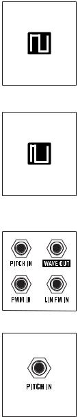
OSCILLATOR PATCH POINTS
Each Matriarch oscillator is equipped with versatile patch points, allowing for a variety of modulation possibilities, including Linear FM (Frequency Modulation) and PWM (Pulse Width Modulation).
NOTE: The patch points for each oscillator are identical.
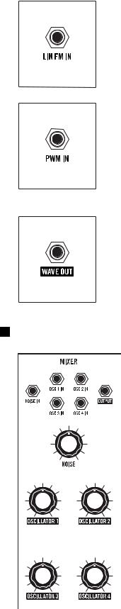
PITCH IN (Exponential Frequency Modulation)
A control signal connected to this input will modulate the Pitch (Frequency) of a patched oscillator and all subsequent oscillators, unless a subsequent oscillator is also receiving a modulation signal via its own PITCH IN jack. This input voltage is added to the voltage from the note played on the keyboard.
NOTE: Connecting a modulation source to the PITCH input on Oscillator 1 will affect the Pitch of Oscillators 1, 2, 3, and 4. Connecting an additional modulation source to the PITCH input of Oscillator 2 will affect the Pitch of Oscillators 2, 3 and 4, and will prevent the modulation signal arriving at the Oscillator 1 PITCH input jack from modulating these oscillators.
TIP: By connecting a modulation source to the Oscillator 1 PITCH IN jack, and a “dead patch” to the Oscillator 2 PITCH IN jack, only Oscillator 1 will receive the modulation signal. A dead patch is a cable connected to a patch point with no connection on the opposite end, used to interrupt normalized signal paths.
CV INPUT: -5V to +5V Control Voltage (1V/Oct)
16
OSCILLATORS (Continued)
LIN FM IN (Linear Frequency Modulation)
Connecting an audio signal or high-frequency control signal to this input introduces Linear Frequency Modulation (FM) to a patched oscillator, which can be useful in creating brash, metallic, or bell-like tones.
CV INPUT: -5V to +5V Control Voltage (AC coupled)
PWM IN
A control signal connected to this input will modulate the pulse width of the Square or Narrow Pulse waveform selected by a patched oscillator. Pulse Width Modulation (PWM) varies the duty cycle, or pulse width of a wave, and thereby changes its harmonic content. Among other things, PWM is often used to mimic the sound of ensemble strings and to thicken bass sounds.
CV INPUT: -5V to +5V
WAVE OUT
The audio signal available at this output is determined by the settings of the
OCTAVE, FREQUENCY, SYNC and WAVEFORM knobs of a patched oscillator.
CV / AUDIO OUTPUT: 10V peak-to-peak
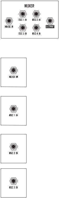
MIXER
The Mixer is where all of the sound sources within Matriarch are blended together before being passed on to the Filter. Patch points in the Mixer allow each hardwired source (Oscillators 1 – 4 and Noise) to be replaced with an external audio signal. There is also a line-level Instrument Input on Matriarch’s rear panel that feeds directly to the Mixer.
MODULE PROVENANCE: Matriarch’s Mixer is based on the classic
Moog CP3 module.
17

MIXER (Continued)
NOISE
Matriarch features a built-in White Noise generator. Noise is an unpitched sound source that can be a useful tool for creating powerful percussion sounds, or for adding a gentle breath to synthesized wind instruments such as flutes. The NOISE knob sets the level of the White Noise generator as it enters the Mixer. Settings above 11 O’clock will impart gentle distortion, while higher settings will result in more overdriven sounds.
NOTE: A High Pass Filter (HPF) can be applied to the noise signal using the Global Settings on page 63, allowing the color (or harmonic strength per frequency band) to be adjusted.
OSCILLATOR 1
The OSCILLATOR 1 knob sets the level of Oscillator 1 as it enters the Mixer. Settings above 11 O’clock will impart gentle distortion, while higher settings will result in more overdriven tones.
OSCILLATOR 2
The OSCILLATOR 2 knob sets the level of Oscillator 2 as it enters the Mixer. Settings above 11 O’clock will impart gentle distortion, while higher settings will result in more overdriven tones.
OSCILLATOR 3
The OSCILLATOR 3 knob sets the level of Oscillator 3 as it enters the Mixer. Settings above 11 O’clock will impart gentle distortion, while higher settings will result in more overdriven tones.
OSCILLATOR 4
The OSCILLATOR 4 knob sets the level of Oscillator 4 as it enters the Mixer. Settings above 11 O’clock will impart gentle distortion, while higher settings will result in more overdriven tones.
18
MIXER (Continued)
MIXER PATCH POINTS
These Mixer module patch points provide a convenient way to replace any or all of the internal sound sources entering the Mixer with an external sound source, such as a Eurorack oscillator or other electronic music devices.
TIP: Matriarch’s Mixer is DC coupled, which means it can also be used to sum multiple control voltages. Combining audio signals with control signals will yield results that can be unique, bizarre, or completely undesirable.
PERFORMANCE NOTE: Mix gates are located on Oscillator channels 1-4. When in 2-Note or 4-Note Paraphonic mode, external sources will be dynamically muted just as the onboard oscillators would.
NOISE IN
When an external audio source is patched to this input, the Noise generator will be removed from the signal path, and the NOISE knob will control the level of the new source.
AUDIO INPUT: -5V to +5V (10V peak-to-peak)
OSC 1 IN
When an external audio source is patched to this input, Oscillator 1 will be removed from the signal path, and the OSCILLATOR 1 knob will control the level of the new source.
AUDIO INPUT: -5V to +5V (10V peak-to-peak)
OSC 2 IN
When an external audio source is patched to this input, Oscillator 2 will be removed from the signal path, and the OSCILLATOR 2 knob will control the level of the new source.
AUDIO INPUT: -5V to +5V (10V peak-to-peak)
OSC 3 IN
When an external audio source is patched to this input, Oscillator 3 will be removed from the signal path, and the OSCILLATOR 3 knob will control the level of the new source.
AUDIO INPUT: -5V to +5V (10V peak-to-peak)
19
MIXER (Continued)
OSC 4 IN
When an external audio source is patched to this input, Oscillator 4 will be removed from the signal path, and the OSCILLATOR 4 knob will control the level of the new source.
AUDIO INPUT: -5V to +5V (10V peak-to-peak)
OUTPUT
The combined signal of all audio sources connected to the Mixer is available at this output.
AUDIO OUTPUT: 10V peak-to-peak
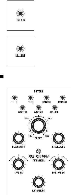
FILTERS
Filters are paramount in shaping the tone of your sound. While an oscillator’s waveform determines the harmonic content of a raw wave, it is the filter that allows that harmonic content to be shaped, sculpted, and modulated over time to create something truly unique.
Matriarch’s filters operate in one of three selectable modes; Series, Parallel, or Stereo. Depending on the current setting of the FILTER MODE switch, VCF 1 has the ability to operate in either High Pass or Low Pass mode, while VCF 2 maintains its Low Pass operation at all times.
NOTE: A stereo signal path is available from the filters onward.
MODULE PROVENANCE: Matriarch’s filters are based on the classic Moog 904A module.
20
FILTERS (Continued)
200Hz |
2kHz |
20Hz |
20kHz |
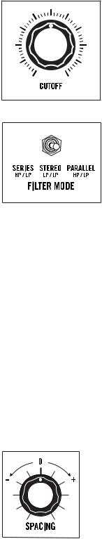
CUTOFF
Matriarch’s CUTOFF knob specifies the Filter Cutoff frequency for both VCF 1 and VCF 2 in a linked fashion. The SPACING knob is used to offset the frequency of VCF 1, above or below the Cutoff Frequency of VCF 2.
FILTER MODE
This three-position switch defines how VCF 1 and VCF 2 are configured, and how they will interact with each other.
HP / LP SERIES
In this mode, VCF 1 is configured as a High Pass filter and VCF 2 is configured as Low Pass filter. Signal passes from the Mixer module into VCF 1 (High Pass), and then is routed into VCF 2 (Low Pass). The mono output signal from VCF 2 feeds both VCA 1 and VCA 2.
NOTE: This is the foundation for creating a Band Pass filter.
LP / LP STEREO
In this mode, VCF 1 and VCF 2 function independently as Low Pass filters. Both receive the same signal from the Mixer module. VCF 1 is routed to VCA 1, and VCF 2 is routed to VCA 2. This creates a true-stereo signal path to the outputs.
HP / LP PARALLEL
In this mode, VCF 1 is configured as a High Pass filter and VCF 2 is configured as a Low Pass filter. Both receive the same signal from the Mixer module, and their outputs are combined into a monaural signal that feeds both VCA 1 and VCA 2.
NOTE: This is the foundation for creating a Notch filter.
REFERENCE: To see Filter Mode Signal Flow diagrams see Page 72-73.
SPACING
Both VCF 1 and VCF 2 share the same Cutoff frequency value as determined by the CUTOFF knob. This SPACING knob specifies an offset in the value of the Cutoff frequency of VCF 1 in relation to the Cutoff frequency of VCF 2. This knob is bipolar; so turning this knob clockwise from center (+) increases the Cutoff frequency of VCF 1 to a value above that of VCF 2. Turning this knob counterclockwise (-) decreases the Cutoff frequency of VCF 1 to a value below that of VCF 2. In the center position, the Cutoff frequency of VCF 1 is equal to the Cutoff frequency of VCF 2.
NOTE: The SPACING knob only affects the Cutoff Frequency of VCF 1.
21
FILTERS (Continued)
RESONANCE 1 & 2
Resonance channels a portion of the Filter’s output back to the input of the Filter, creating an emphasis peak at the Filter’s Cutoff frequency. This is useful for adding focus, funkiness, or “sci-fi laser blasts” to a sound.
The RESONANCE 1 knob sets the amount of Resonance being applied to VCF 1, while the RESONANCE 2 knob sets the amount of Resonance being applied to VCF 2.
NOTE: A RESONANCE knob setting of around 3 O’clock or more will cause the filter to self-oscillate.
ENVELOPE AMT (Envelope Amount)
The ENVELOPE AMT knob determines how much of the control signal created by the Filter Envelope will be applied to the Filter’s Cutoff frequency over time. This knob is bipolar, so turning the ENVELOPE AMT knob clockwise from center will raise the Filter’s Cutoff frequency from the CUTOFF knob’s current setting. Turning it counterclockwise from center will lower the Filter’s Cutoff frequency from the CUTOFF knob’s current setting.
NOTE: Negative (or inverse) modulation simply flips the shape of the Filter Envelope generator. Instead of the Attack parameter raising the Cutoff frequency over time, the Attack parameter will lower the Cutoff frequency by the same amount, in the same period of time.
KB TRACKING (Keyboard Tracking)
Keyboard Tracking allows the note being played on the keyboard itself to be used as a modulation source for the Filter’s Cutoff frequency. Higher notes on the keyboard may be perceived as being brighter than lower notes – especially when the filter is in the Low Pass mode.
When the KB TRACKING knob is set to its maximum value (fully clockwise), the Filter will track the keyboard using the same 1 volt/octave scheme as the oscillators. At its minimum value (fully counterclockwise), the KB TRACKING knob will have no effect.
TIP: Setting the RESONANCE and KB TRACKING knobs to maximum allows the keyboard to play the Filter(s) similarly to an oscillator.
22
FILTERS (Continued)
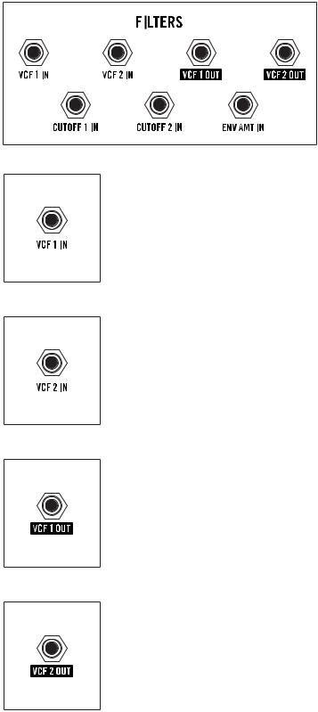
FILTER PATCH POINTS
These Filter module patch points provide a convenient way to independently modulate the Cutoff frequency of VCF 1 and/or VCF 2, and to modulate the value of the ENVELOPE AMT knob. In addition, audio inputs and outputs allow each filter to be used as a stand-alone processor for filtering any internal or external sound source.
VCF 1 IN
The input to VCF 1 is connected to the output of the Mixer module. Patching an audio signal to this input overrides the Mixer signal, allowing any audio source to be processed by VCF 1.
NOTE: The path and mode of VCF 1 are determined by the FILTER MODE switch.
AUDIO INPUT: -5V to +5V
VCF 2 IN
The input of VCF 2 is connected to the output of the Mixer or VCF 1, depending on the position of the FILTER MODE switch. Patching an audio signal to this input overrides this signal, allowing any audio source to be processed
by VCF 2 using the filter’s current settings.
AUDIO INPUT: -5V to +5V
VCF 1 OUT
The audio output of VCF 1 is available via this jack, allowing it to be sent to any input on Matriarch itself, or to an external electronic music device.
AUDIO OUTPUT: 10V peak-to-peak
NOTE: VCF 1 can be used as a stand-alone audio processor.
VCF 2 OUT
The audio output of VCF 2 is available via this jack, allowing it to be sent to any input on Matriarch itself, or to an external electronic music device.
AUDIO OUTPUT: 10V peak-to-peak
NOTE: VCF 2 can be used as a stand-alone audio processor.
23
FILTERS (Continued)
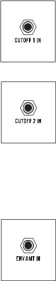
CUTOFF 1 IN
A control signal connected here will modulate the Cutoff frequency of VCF 1. This is based on the current CUTOFF, SPACING, ENVELOPE AMT, and KB TRACKING knob settings.
CV INPUT: -5V to +5V
CUTOFF 2 IN
A control signal connected here will modulate the Cutoff frequency of VCF 2. This is based on the current CUTOFF, ENVELOPE AMT, and KB TRACKING knob settings.
CV INPUT: -5V to +5V
NOTE: A control signal arriving at the CUTOFF 1 IN jack is normalled to the CUTOFF 2 IN jack and will affect the Cutoff frequency of both VCF 1 and VCF 2. A control signal connected to the CUTOFF 2 IN jack will affect only the Cutoff frequency of VCF 2.
TIP: Connecting a modulation source to the CUTOFF 1 IN jack, and a “dead patch” to the CUTOFF 2 IN jack will prevent the modulation signal from reaching VCF 2. A dead patch is a cable connected to a patch point with no connection on the opposite end, used to interrupt normalized signal paths.
ENV AMT IN
A control signal connected here will modulate the value of the ENVELOPE AMT knob, thereby changing how much influence the Filter Envelope has over the Filter Cutoff frequency.
CV INPUT: -5V to +5V
24
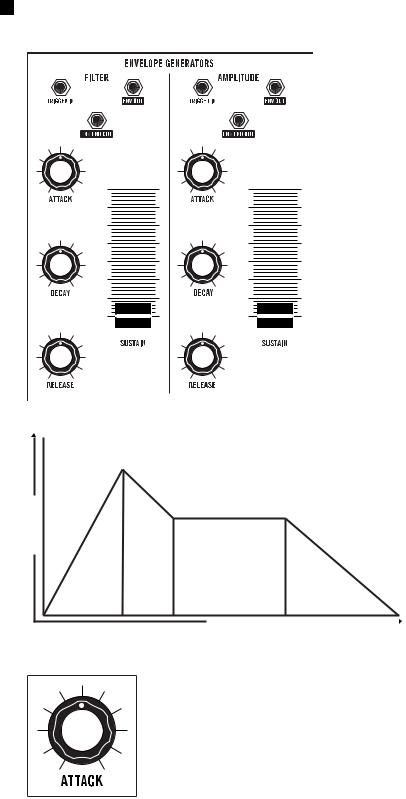
ENVELOPE GENERATORS (ADSR)
edutilpma
Sounds change over time. How they change over time is part of what makes each one unique. Some sounds begin abruptly, like the strike of a
drum. Some sounds end just as quickly, and some linger like a held chord on a piano. We call this the envelope of a sound. Matriarch uses a pair of identical Envelope Generators to create control voltages that also change over time. This type of control voltage can be applied to the amplitude of the sound, changing its volume over time. This same type of control voltage can also be used to affect the Cutoff frequency of the Filter over time, creating changes in timbre, or tone.
NOTE: In a semi-modular synthesizer such as Matriarch, an Envelope Generator can be patched to modulate any controllable parameter over time.
MODULE PROVENANCE: Matriarch’s Envelope
Generators are based on the classic Moog 911 module.
Regardless of how the Envelope is applied, there are four main stages: Attack time, Decay time, Sustain level, and Release time. These controls are identical for both Envelope Generators.
kcatta |
ayced |
niatsus |
esaeler |
Of these four stages, three relate |
|
to time, and are controlled by |
|||||
|
|
|
|
||
|
|
|
|
rotary knobs. Only the Sustain |
|
|
|
|
|
stage relates to level; it is |
|
|
|
time |
|
controlled using a slider. |
|
|
|
|
ATTACK
The ATTACK knob determines the amount of time required for the control signal to rise from zero to its maximum level once a key is pressed. The ATTACK knob has a range from 2 milliseconds to 10 seconds. Fast attacks are useful for creating plucked sounds, while slow attacks are more useful for creating bowed string sounds and swells. Brass swells will often have a faster Amplitude Attack and a slower Filter Attack.
25
 Loading...