


DS2000
USER'S MANUAL (rev.C)
GB-4534

|
|
INDEX |
I.1 |
|
|
INDEX OF REVISIONS |
|
|
|
|
|
Revision |
Date |
Description |
Updated section |
|
|
|
|
0 |
Jul 99 |
Preliminary |
|
1 |
Dec 99 |
Initial Release |
|
2 |
Jan 00 |
Correct errors |
|
3 |
Mar 00 |
Change fuses according UL, correct |
|
|
|
miscellaneous errors |
|
4 |
Jan 01 |
Changes of control board |
All |
5 |
May 02 |
Update on new drives sizes, error correction |
All |
6 |
Feb 04 |
Update on new SW release |
Index, |
|
|
|
Section 3-4-7, |
|
|
|
Appendix |
7 |
May 04 |
Update |
All |
8 |
Jul 04 |
New UL requirement |
Table of contents |
9 |
Oct 04 |
Deleted DSloader section, update |
All |
B |
Jan 06 |
New size E, update section 8 – Restart Interlock |
All |
|
|
Function, update new software releases, correct |
|
|
|
miscellaneous errors |
|
C |
Sep 06 |
G motor resolver connection, APHAPOS |
Par. 2.11.2.1, |
|
|
parameter, update figures Size E, update section |
2.11.3.2, 3.3.4, |
|
|
8 – Restart Interlock Function, correct |
6.2.1, 6.2.2, 6.3.1, |
|
|
miscellaneous errors |
6.7.1.5 |
|
|
|
Fig. 2.4.1, 2.5, 2.6, |
|
|
|
2.8, 2.8.1, 2.14, |
|
|
|
3.5.1 |
|
|
|
Section 8 |
DS2000 USER’S MANUAL (rev.C)

I.2 INDEX
INDEX OF CONTENTS
Index |
Introduction |
I.1 |
|
Using the manual |
I.2 |
|
Accident protection |
I.3 |
|
EC declaration of conformity |
I.4 |
|
EC requirements |
I.5 |
|
UL authorization |
I.6 |
|
UL requirements |
I.7 |
|
ICEPI certificate |
I.8 |
|
Safety requirements |
I.9 |
|
(Restart Interlock Function) |
|
|
Legal aspects |
I.10 |
Section 1 |
Introduction |
1.1 |
Description |
Product range |
1.2 |
|
General features |
1.3 |
|
Technical data |
1.4 |
|
Standard versions codes |
1.5 |
|
Special versions codes |
1.6 |
|
Options |
1.7 |
|
Serial number – Nameplate |
1.8 |
Section 2 |
Introduction |
2.1 |
Wiring and installation |
Dimensions and drilling jig |
2.2 |
|
External fuses |
2.3 |
|
Power dissipation |
2.4 |
|
Soft-start |
2.5 |
|
Recovery circuit |
2.6 |
|
Fans |
2.7 |
|
Reset |
2.8 |
|
Connection cables |
2.9 |
|
AWG/mm2 conversion |
2.10 |
|
Wiring and connectors |
2.11 |
|
Drive starting sequence |
2.12 |
|
Starting sequence times |
2.13 |
|
Dynamic braking |
2.14 |
|
Power off |
2.15 |
|
Mechanical braking |
2.16 |
Section 3 |
Introduction |
3.1 |
Electromagnetic |
European directive (89/336/EEC) |
3.2 |
compatibility (EMC) |
Filters |
3.3 |
|
Wiring and grounding |
3.4 |
|
Recovery resistor |
3.5 |
|
Screening |
3.6 |
|
Safety aspects |
3.7 |
DS2000 USER’S MANUAL (rev.C)

|
INDEX |
I.3 |
Section 4 |
Introduction |
4.1 |
Starting |
Drive setting up information |
4.2 |
|
First Start-up |
4.3 |
|
Configuration for installation in electrical cabinet |
4.4 |
Section 5 |
Introduction |
5.1 |
Component description |
High power input section |
5.2 |
|
High power output section |
5.3 |
|
Control section |
5.4 |
Section 6 |
Introduction |
6.1 |
Commands |
Motor parameters menu |
6.2 |
|
Drive parameters menu |
6.3 |
|
Control loops parameters menu |
6.4 |
|
Drive enable menu |
6.5 |
|
Display variables menu |
6.6 |
|
Utility menu |
6.7 |
|
Keyboard lock menu |
6.8 |
|
Fault detection menu |
6.9 |
Section 7 |
Introduction |
7.1 |
Troubleshooting |
Faults on drive power supply circuit |
7.2 |
|
Faults on drive output section |
7.3 |
|
Faults on feedback section |
7.4 |
|
Control loops troubles |
7.5 |
|
Motor troubles |
7.6 |
|
Recovery resistor troubles |
7.7 |
Section 8 |
Intended application |
8.1 |
Restart interlock circuit |
Restart interlock function |
8.2 |
(Optional) |
Safety requirements |
8.3 |
|
Restart interlock circuit |
8.4 |
|
Restart interlock connections |
8.5 |
|
Safety relays – Technical data |
8.6 |
|
Application example |
8.7 |
|
Sequence and procedure using the restart |
8.8 |
|
interlock |
|
|
Checking the restart interlock |
8.9 |
|
External plausibility tests |
8.10 |
|
Installation and routine test |
8.11 |
|
RIC identification on the nameplate |
8.12 |
Appendix |
Appendix A - Motors technical data |
|
|
Appendix B - FC series technical data |
|
|
Appendix C - Active software release |
|
|
Appendix D - Obsolete software release |
|
DS2000 USER’S MANUAL (rev.C)

I.4 |
INDEX |
I.1 INTRODUCTION
This manual refers to DS 2000 “The Motion Solution” drive, with SW Release 3.20X.
The manuals from 0 to 3 release refers to DS2000 drives and SW release below 2.00X.
The manuals from 4 to 5 release refers to DS2000 “The Motion Solution” drive, with SW release 3.00X and 3.10X.
New characteristics and added functionalities on DS2000 Software Release 3.200:
•I2T IGBT Protection. This functionality allows to protect IGBT modules from overheating, due to excessive phase current flowing (particularly at low frequencies or locked rotor).
When the protection activates the drive can be disabled or the current flowing can be limited. This functionality can be activated or deactivated from menu. Activating this protection the Notch Filter will be automatically deactivated. I2T IGBT Protection and NOTCH FILTER cannot be used together.
•Anti-Free-Wheeling (AFW). This functionality allows to have an emergency motor stop in case of NO POWER, MOTOR OVERHEATING and DRIVE OVERHEATING. The motor will brake with the deceleration value eventually set in menu. This functionality can be activated or deactivated from menu.
•Regen Resistor Protection. Some customer applications have shown an intense continuous utilization of the regen resistor that sometimes ends with its damage or even breaking. To avoid this problem a new functionality has been developed within the new DS2000 Firmware Release 3.200: this algorithm estimates the growing of the resistor temperature and, depending on the manufacturer data (nominal power, maximum power and time at peak power), protects it from dangerous overheating.
•FAS G Defluxing. This modification improves motor performances at high speed introducing a defluxing component (sinusoidal current phase shifting) starting from a speed value and with a maximum angle value to be set in the menu. This functionality can be activated or deactivated from menu using its related parameter.
•Dead Band on analog reference. A dead Band on analog reference can be introduced (centered on zero crossing and symmetric in both directions) with an amplitude selected with the menu. It eliminates possible offsets that can cause slow motor shaft drift rotations. This functionality can be activated or deactivated from menu using its related parameter.
•PTC/NTC Selection. PTC/NTC motor thermal sensor can be selected using menu.
•Automatic Current Offset Compensation. This functionality automatically auto-activates when drive is disabled and it repeats its calculations until the drive is off. When the drive is enable, the last calculated offset value is memorized and used in current loop. When the drive is disabled again, this function activates and compensates also possible thermal drifts.
DS2000 USER’S MANUAL (rev.C)

INDEX |
I.5 |
•ENC/OUT Zero Marker Calibration. This functionality is activated through the “ENC/OUT
MARKER CALIBRATION” in the UTILITY menu and shifts the Zero Marker on the electric turn. It can be useful to align the ENC/OUT Marker with mechanical zero of the machine.
•Digital speed reference parameter saving. Digital speed reference parameter set in CURRENT LOOP PARAMETERS, SPEED LOOP menu can now be saved.
•Parameter range modification: motor speed and motor Rw.
-Motor speed parameter range has been changed from 300/9999 to 100/9999;
-Motor Rw parameter range has been changed from da 0/30.0 to 0/100.0;
-IOFFS U and V parameter range has been changed from -100/100 to -500/500;
-RECOVERY RESISTOR parameter has been changed from 5/100 to 3/100;
NOTE: this software can be installed on the DS2000 with 3.xxx software version: please contact Moog service before update the drives.
NOTE: this software is totally compatible with the interface Windrive GUI; with 3.1xx or previous release use DSLoader interface.
I.2 USING THE MANUAL
This manual provides the necessary information for a proper installation and use of the DS2000 servodrive.
The DS2000 was designed to be easily installed; it is not necessary any specific skill concerning servodrives to start it up.
Anyway, the installer should have basics of electronics/electrotechnics, of servodrives, and of safety.
The DS 2000 is a digital servodrive, which can be configured via software as a computer, according to the application requirements.
It is recommended to read carefully the manual before the installation.
After the installation, and before starting up the motor it is also recommended to check all the system parameters to ensure a correct system configuration.
Particular attention must be used to safety instructions.
DS2000 USER’S MANUAL (rev.C)

I.6 |
INDEX |
I.3 ACCIDENT PROTECTION
The safety instructions provided in this Manual are included to prevent injury to personnel (WARNINGS) or damage to equipment (CAUTIONS).
WARNING: High Voltage. BUS BAR's can have voltage ≥810Vdc even after switching off (capacitive voltage). Discharge Time approx. 6 Minutes.
WARNING: High Voltage. The recovery resistor is connected to the BUS BAR’s and can have voltage ≥810Vdc.
WARNING: do not touch recovery resistor during operation to avoid scalds.
CAUTION: it is recommended to disconnect the drive and the EMC filters to carry out the AC
Voltage Tests of EN 60204-1 (1997), par.19.4, in order to not damage the Y-type capacitors between phases and ground. Moreover the DC voltage dielectric test required by EN 50178
(1997), product family standard, has been carried out in factory as a routine test. The DC Insulation Resistance Tests of EN 60204-1 (1997), par.19.3, may be carried out without disconnecting the drive and the EMC filters.
CAUTION: when required for an emergency stop, opening U2-V2-W2 pins and closing motor phases to resistors, must be preceded by disabling the axis. The delay time must be at least 30 ms.
CAUTION: in case of repetitive switching on and off, waits 1 minute between off and on.
CAUTION: do not exceed the tightening torque of the table (but see proper data sheets for the tightening torque of input capacitors and power modules and see section 2 of this manual for the tightening torque of terminal blocks).
Screw thread |
Tightening torque |
||
[Nm] |
[lb in] |
||
|
|||
M3 |
1.00 |
8.85 |
|
M4 |
3.00 |
26.55 |
|
M5 |
6.00 |
53.10 |
|
M6 |
8.00 |
70.80 |
|
M8 |
20.00 |
177.00 |
|
DS2000 USER’S MANUAL (rev.C)

INDEX |
I.7 |
I.4 EC DECLARATION OF CONFORMITY
DS2000 USER’S MANUAL (rev.C)

I.8 |
INDEX |
I.5 EC REQUIREMENTS
Cautionary Marking. See previous page.
Protection against electric shock. Electronic Equipment intended for installation in closed electrical operating areas kept locked. Where Electronic Equipment requires manual intervention, 412.2.1 of HD 384.4.41 S2 shall be consulted.
Fixed connection for protection. The equipment may have a continuous leakage current of more than A.C. 3.5 mA or D.C. 10 mA in normal use and a fixed ground connection is required for protection.
RCD. When the protection in installations with regard to indirect contact is achieved by means of an RCD, their appropriate function/combination shall be verified. In any case only a residual-current-operated protective device (RCD) of Type B is allowed. In fact a
D.C component can occur in the fault current in the event of a fault connection to earth.
Climatic Conditions. Equipment intended to operate within its performance specification over the range of Class 3K3, as defined in table 1 of EN 60721-3-1, EN 60721-3-2, EN 60721-3-3, EN 60721-3-4, partly modified.
Pollution Degree 2 Installation. The equipment shall be placed in a pollution degree 2 environment, where normally only non-conductive pollution occurs. Occasionally, however, a temporary conductivity caused by condensation is to be expected, when the electronic equipment is out of operation.
EMC Requirements. The installer of the equipment is responsible for ensuring compliance with the EMC standards that apply where the equipment is to be used. Product conformity is subjected to filters installation and to recommended procedures, as from section 3 of this manual.
Second Environment (EMC). Equipment intended to be connected to an industrial lowvoltage power supply network, or public network that does not supply buildings used for domestic purposes (second environment, according to EMC Standards). It is not intended to be used on a low-voltage public network that supplies domestic premises (first environment). Radio frequency interference is expected if used on such a network.
Recovery Resistor Cable. Shielding of the recovery resistor cable, provided in kit for test purposes, is recommended for ensuring compliance with the EMC standards.
Large-Scale Stationary Industrial Tools (WEEE, RoHS). Equipment intended for installation as part of large-scale stationary industrial tools, covered by the exception of
Annex IA, No.6, of the European Directives 2002/96/EC (WEEE) and 2002/95/EC (RoHS).
DS2000 USER’S MANUAL (rev.C)
INDEX |
I.9 |
I.6 UL AUTHORIZATION (page 1)
DS2000 USER’S MANUAL (rev.C)
I.10 |
INDEX |
UL AUTHORIZATION (page 2)
DS2000 USER’S MANUAL (rev.C)

INDEX |
I.11 |
I.7 UL REQUIREMENTS
•These Brushless Servo-Drives shall be assembled with the guidelines specified in this
Manual. Only the configurations with the components tested and described in the UL Report, file E194181, Vol.1, Sec.1, Issue date 01-21-00 and following Revisions can bear the Listing Mark.
•These drives shall be used within their ratings, as specified in the marking of the equipment.
•Cautionary Marking. See Accident Protection page.
•Surrounding Air Temperature. "Maximum Surrounding Air Temperature 40°C". In the final installation considerations shall be given for the need of repeating Temperature test if the unit is mounted with a different Surrounding Air conditions.
•Pollution degree 2 Installation. The drive must be placed in a pollution degree 2 Environment.
•Environmental designation. “Open Type Equipment”.
•Short Circuit Ratings.
DS2000 3/9, 4/12, 6/15, 8/22, 14/42, 20/45, 25/70, 35/90, 50/140: “Equipment suitable for use on a circuit capable of delivering not more than 5000 rms Symmetrical
Amperes, 460 Vac +10% maximum”
DS2000 60/180, 100/300: “Equipment suitable for use on a circuit capable of delivering not more than 10000 rms Symmetrical Amperes, 460 Vac +10% maximum”
•Branch Circuit Protection. The Branch Circuit Protection for Short Circuit shall be provided in the end-use applications by external R/C Fuses (JFHR2), manufactured by
Busman Div Cooper (UK) LTD, Semiconductor fuse type, rated 660 Vac, 200 kA A.I.C., Mod. No. as follows:
DS2000 3/9, 4/12, 6/15, 8/22, 14/42: Mod. No. 50 FE, rated 50 Amps
DS2000 20/45, 25/70, 35/90: Mod. No. 100 FE, rated 100 Amps
DS2000 50/140, 60/180: Mod. No. 160 FEE, rated 160 Amps
DS2000 100/300: Mod. No, 315-FM, rated 315 Amps
•Overspeed Protection. The Power Conversion Equipment is incorporating an Overspeed
Protection. See MV command in section 6.
•Overvoltage Control. In the equipment the Overvoltage is controlled by a Transient
Suppressive device, with 1500 V Clamping Voltage and min 120 J (10x1000 us or 2 ms) Energy Handling Capability. See also “Bus not normal” protection in section 6.
•Overload Protection. The equipment does not incorporate internal overload protection for the motor load. The drive is intended to be used with motors that must have integral thermal protection through a PTC or NTC. The overtemperature fault of the drive will trip when the PTC reaches 2 kW or 6.5kW for the NTC. See J4 connector in section 2 of this manual for wiring.
DS2000 USER’S MANUAL (rev.C)

I.12 |
INDEX |
•Over-Current Protection. The drive is provided with a current limiting circuitry. See
ANALOG ILIMIT and I2T commands in section 6.
•Wiring. Wiring shall be made by stranded and/or solid, copper (Cu), 60/75°C (140/167°F) conductor only, and, for terminal blocks, the tightening torque values specified in section 2 of this manual shall be applied. These requirements do not pertain to control circuit terminals.
•Wiring of Recovery Resistor. The Dynamic Brake Unit Recovery Resistor, when external, shall have the connection wiring made with R/C (AVLV2) or insulated with R/C (YDPU2) or R/C (UZCW2) in the end-use installation.
•Transient Suppression Devices. Input power wiring, only for size A and B, shall be protected by external Transient Suppression Devices, such as varistors or transient voltage surge protections, evaluated to the component requirements in UL1449. the following devices are recommended:
|
Ref. |
|
TVSS |
|
Rating |
|
|
||
Drive |
Manufacturer |
Operating |
Clamping |
Maximum |
Max |
Qty |
|||
|
Code |
|
Mod. No. |
Voltage |
Voltage |
Energy (J) |
Op. |
|
|
|
|
|
|
(Vac) |
(Vac) |
Temp |
|
||
|
|
|
|
|
|
||||
|
|
Littelfuse Inc |
V-575-LA-40- |
575 Vrms |
1500 |
120 |
85°C |
|
|
|
|
A |
max |
(10x1000µs) |
|
||||
|
|
|
|
|
|
||||
A and B |
|
|
S14-K-550 |
550 Vrms |
1500 |
120 |
85°C |
|
|
AS5046 |
Epcos Ohg |
max |
(2ms) |
3 |
|||||
|
|
|
|||||||
size |
S20-K-550 |
550 Vrms |
1500 |
210 |
85°C |
||||
|
|
|
|||||||
|
|
|
max |
(2ms) |
|
||||
|
|
|
|
|
|
|
|||
|
|
S A BC |
2322 595.551 |
550 Vrms |
1500 |
160 |
85°C |
|
|
|
|
Components NV |
max |
(10x1000µs) |
|
||||
|
|
|
|
|
|
||||
DS2000 USER’S MANUAL (rev.C)

INDEX |
I.13 |
I.8 ICEPI CERTIFICATE
DS2000 USER’S MANUAL (rev.C)

I.14 |
INDEX |
I.9 SAFETY REQUIREMENTS (RESTART INTERLOCK FUNCTION)
•Complete Standstill. The Restart Interlock safety function prevents motor unexpectedly starting from standstill. This circuit can be used in the “Safe Standstill” machine function.
When the motor is rotating, the switching-on of the Restart Interlock provides an uncontrolled stop (category 0 according to EN 60204-1:1997). When a controlled stop of category 1, according to EN 60204-1:1997, is requested, the condition of stopped motor must be assured. The final machine must be able to stop the motor.
WARNING: The designer must evaluate the machine stopping time during the risk assessment even in case of failure. The machine can present a dangerous overrun in case of failure of the drive. Other protective measure are needed to achieve a safe condition.
•Environmental Conditions. Equipment intended to operate within the following environmental conditions:
◊Ambient temperature: 0 to +40°C
◊EMC immunity: according to EN 61800-3/A11:2000 (Adjustable speed electrical power drive systems. Part 3: EMC product standard including specific test methods). Second environment (industrial)
◊Vibration immunity: 2 to 12Hz, 1.5 mm amplitude (peak); 12 to 200Hz, 1 g acceleration
◊Shock immunity: 10 g, half sine, 11 ms, according to EN 60721-3-3:1995, Class 3M4
•Enlosure. Electronic Equipment intended for installation in an enclosure providing at least IP54 protection.
•Pollution Degree 2. The equipment shall be installed in a pollution degree 2 environment, where normally only non-conductive pollution occurs. Occasionally, however, a temporary conductivity caused by condensation is to be expected, when the electronic equipment is out of operation.
WARNING: When the Restart Interlock Circuit is activated, the motor can no longer generate a torque. Motors which are not automatically clamped when powered down (e.g. vertical/inclined axes), must be clamped using a mechanical brake
DS2000 USER’S MANUAL (rev.C)

INDEX |
I.15 |
I.10 LEGAL ASPECTS
This manual can be used only by final Customers/Users of the Moog product it describes and only for proper installation purposes.
This manual cannot be reproduced in whole or in part without the prior written consent of Moog.
No transmission or diffusion of this manual, under electronic, mechanical, or printed form, is allowed.
Moog issued this manual attempting to ensure a complete information; anyway, Moog shall not be liable for errors or omissions contained herein and for incidental or consequential damages due to the above mentioned errors and omissions.
Moog reserves the right to change and update this manual without notice.
This manual has a merely information purpose. There is no obligation for Moog as regard the correspondence of the product features described in the manual with the features of the real product purchased by the final Customer/User.
No statement or sentence contained in this manual implies further legal obligations different from the ones contained in each single sale or supply contract concerning Moog products.
DS2000 USER’S MANUAL (rev.C)

I.16 |
INDEX |
THIS PAGE INTENTIONALLY BLANK
DS2000 USER’S MANUAL (rev.C)

SECTION ONE – DESCRIPTION |
1.1 |
1. DESCRIPTION
1.1 INTRODUCTION
This section describes the DS2000 drive series, providing information about the coding system. Such data allow understanding the DS2000 characteristics and makes clear the necessary concepts to access the following sections.
DS2000 USER’S MANUAL (rev.C)

1.2 SECTION ONE – DESCRIPTION
1.2 PRODUCT RANGE
DS2000 is a full digital drive series for permanent magnet synchronous servomotors (hereinafter: brushless) and for vector control asynchronous servomotors (hereinafter: asynchronous).
The range is made up of 11 models, corresponding to 3, 4, 6, 8, 14, 20, 25, 30, 50, 60 and
100 Arms nominal currents.
The standard transducers provided with the motor are the incremental encoder or the resolver (with its simulated encoder).
The recovery resistors are placed outside the drive; only the 3, 4, and 6 A models can be equipped with built-in recovery resistor (optional).
DS2000 drive is provided together with this manual and the Application Notes in the Appendix of DS2000 user’s manual, for a deep understanding and the best use of the product.
1.3 GENERAL FEATURES
The DS2000 features provide the automation industry with the best response to the hardest requirements related to motion control:
FULL DIGITAL:
•Speed and current control loops and many other functions, as the DC BUS status monitoring, the soft-start and recovery circuit management, and the protections thresholds detection are carried out through numeric algorithms.
•The digital mode allows a maximum stability related to the aging, the temperature and the various application cases.
•Settings are carried out through numbers calculated by means of analytic models and do not depend upon analog calibrations.
FLEXIBLE:
•Any brushless motor can be very well driven by entering a maximum of 8 parameters which adjust the current loop and identify the motor electromechanical characteristics (peak current, electromotive force, inductance, resistor, poles number, voltage rating, speed).
•Any asynchronous motor can be very well driven by vector control, working as a brushless servomotor; by entering the magnetization current (ID) and the slip gain
(frequency) additional parameters it is possible to use any kind of asynchronous motor. The other parameters, the ones in connection with the hardware features in common with brushless motors, remain active.
•The motor transducer can be both a resolver (2 to 24 poles) and an incremental encoder (1024 to 8192 pulses).
•It is possible to program the device in 2 different languages: Italian and English. The required language should be specified in the purchase order.
•The power supply voltage range can be from Three-phase 65 Vac to 510 Vac with no previous setup.
•With power supply voltages lower than 120 Vac Three-phase, it is necessary to supply a 24 Vdc auxiliary voltage.
DS2000 USER’S MANUAL (rev.C)
SECTION ONE – DESCRIPTION |
1.3 |
ADVANCED PERFORMANCE:
•The current loop, based on a traditional PI structure, is provided with automatic compensation algorithms of the EMF and of the KP/KI ratio, as a function of the motor characteristics.
•Hardware calibrations are not necessary for the current loop, but they are necessary for parameters setting.
•Current loops are closed at 10kHz.
•The speed loop is closed at 5kHz.
•Additional phase advance is provided.
1.4TECHNICAL DATA
1.4.1 ELECTRICAL AND MECHANICAL SPECIFICATIONS
Three-phase input voltage rating: |
230Vac to 460Vac ±10%, 50/60 Hz |
|
|||||||
Min/max Three-phase input voltage |
|
|
|
|
|
|
|||
- With 24 Vdc auxiliary input voltage: |
65 / 510 Vac (DC-BUS: 80 / 720 Vdc) |
|
|||||||
- Without 24 Vdc auxiliary input voltage: |
120 / 510 Vac (DC-BUS: 150 / 720 Vdc) |
|
|||||||
Auxiliary voltage: |
|
24 Vdc ±10% , 1.5A |
|
|
|
||||
Configurable analog references: |
3.2 to 10 Vdc |
|
|
|
|
||||
Max dynamic with encoder: |
|
200 Hz |
|
|
|
|
|||
Switching frequency: |
|
10 kHz |
|
|
|
|
|||
Speed adjustment: |
|
0 to 9999 rpm |
|
|
|
|
|||
Anti-resonance low-pass filter: |
20 to 800 Hz |
|
|
|
|
||||
Filter on reference: |
|
1 to 800 Hz |
|
|
|
|
|||
Notch filter (programmable): |
50 to 1500 Hz |
|
|
|
|
||||
|
|
|
|
|
|
|
|
|
|
|
Model |
|
Output current |
|
Mass |
|
Size |
||
|
|
Nominal |
Max |
|
Peak |
|
|||
|
|
|
(kg) |
|
|||||
|
|
|
(Arms) |
(Arms) |
|
(A) |
|
|
|
|
|
|
|
|
|
|
|||
|
3/9 |
|
3 |
6.4 |
|
9 |
4.5 |
|
A |
|
4/12 |
|
4 |
8.5 |
|
12 |
4.5 |
|
A |
|
6/15 |
|
6 |
10.6 |
|
15 |
4.5 |
|
A |
|
8/22 |
|
8 |
15.6 |
|
22 |
4.5 |
|
A |
|
14/42 |
|
14 |
29.7 |
|
42 |
6 |
|
B |
|
20/45 |
|
20 |
31.8 |
|
45 |
10 |
|
C |
|
25/70 |
|
25 |
49.5 |
|
70 |
10 |
|
C |
|
30/90 |
|
30 |
63.6 |
|
90 |
10 |
|
C |
|
50/140 |
|
50 |
99.0 |
|
140 |
23 |
|
D |
|
60/180 |
|
60 |
127.3 |
|
180 |
23 |
|
D |
|
100/300 |
|
100 |
212.7 |
|
300 |
40 |
|
E |
Tab. 1.0 – Mechanical and electrical characteristics
DS2000 USER’S MANUAL (rev.C)

1.4 |
SECTION ONE – DESCRIPTION |
1.4.2CLIMATIC CONDITIONS
1.4.2.1AMBIENT TEMPERATURE
0°C to +40°C (exceeding EN 60204-1:1997, par.4.4.3).
1.4.2.2 AMBIENT HUMIDITY
5% to 85% with no condensation and no formation of ice (according to EN 50178:1997, weather protected site).
1.4.2.3 ALTITUDE
The electrical equipment is able to operating correctly at altitudes up to 1000m above sea level (according to EN 60204-1:1997, par.4.4.5)
1.4.2.4 TRANSPORTATION AND STORAGE
The electrical equipment withstands the effects of transportation and storage temperatures within a range of –25°C to +55°C and for short periods not exceeding 24 h at up to +70°C (according to EN 60204-1:1997, par.4.5).
1.4.2.5 POLLUTION
The equipment has been designed according to pollution degree 2, where normally only non-conductive pollution occurs. Occasionally, however, a temporary conductivity caused by condensation is to be expected, when the electronic equipment is out of operation.
1.4.3OTHER MECHANICAL SPECIFICATIONS
1.4.3.1IMMUNITY TO MECHANICAL VIBRATION
0.075mm amplitude from 10 Hz to 57 Hz, 1g acceleration from 57 Hz to 150 Hz (according to EN 50178:1997 and to IEC 68-2-6:1995, Fc test).
DS2000 USER’S MANUAL (rev.C)

SECTION ONE – DESCRIPTION |
1.5 |
1.4.4 INTERFACES
•Analog
Speed (or current) reference differential input: 0 +/- 10V (adjustable scale)
Auxiliary input voltage: 24Vdc ±10%
Output Voltage: 15Vdc
Analog output (configurable)
Tachometric signal (adjustable scale)
Peak current limit (trough adjustable analog signal)
Motor temperature (trough PTC or NTC)
Resolver interface
Sine Encoder Interface (optional)
•Digital
RS485 full-duplex serial link
Encoder input (incremental)
Encoder output (incremental)
Reset
Drive OK output
Drive enable input (torque)
Reference enable input (speed)
CAN BUS (optional)
1.4.5 PROTECTIONS
•Motor over temperature
•Drive over temperature
•Input voltage out of tolerance
•Encoder or resolver signal missed
•Encoder or resolver faulty connections
•Axis short circuit (motor and recovery resistor output)
•Recovery resistor missed (overvoltage)
•Recovery resistor overload (software selectable)
•Over speed in torque mode control (if speed is 12% above max set value).
•IGBT over temperature (software selectable)
•Anti-free-wheeling (software selectable)
•Safety – Restart interlock function (optional).
DS2000 USER’S MANUAL (rev.C)

1.6 |
SECTION ONE – DESCRIPTION |
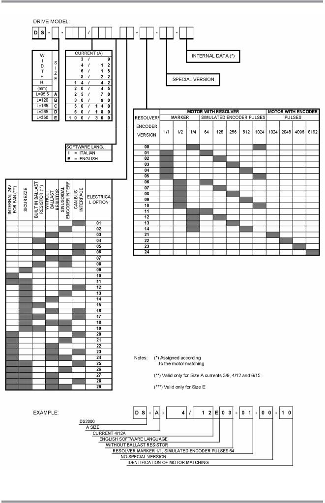
1.5 STANDARD VERSIONS CODES
DS2000 drives are marked by a code identifying both the current supplied by the Model and the eventual internal recovery resistor.
Codes correspond to:
•Standard Italian software drives
•6 poles resolver (transformation ratio:0.29), ¼ marker configured, 1024 simulated encoder pulses
•External recovery resistor, provided with the drive together with mating connectors.
The following table summarizes the drive codes:
Model |
Size |
||
Code |
Type |
||
|
|||
CZ1000C0A |
3/9 |
A |
|
CZ1001C0A |
4/12 |
A |
|
CZ1002C0A |
6/15 |
A |
|
CZ1003C0A |
8/22 |
A |
|
CZ1008C0A |
14/42 |
B |
|
CZ1005C0A |
20/45 |
C |
|
CZ1006C0A |
25/70 |
C |
|
CZ1007C0A |
30/90 |
C |
|
CZ1009C0A |
50/140 |
D |
|
CZ1010C0A |
60/180 |
D |
|
CZ1011C0A |
100/300 |
E |
|
Tab. 1.1 – Standard versions codes
Besides the coding in Tab. 1.1, a new coding formed by a descriptive code has been introduced, which univocally and directly identifies a drive and its configuration.
Fig. 1.1 shows the new codifications .
DS2000 USER’S MANUAL (rev.C)

SECTION ONE – DESCRIPTION |
1.7 |
1.6 SPECIAL VERSIONS CODES
For a limited braking power dissipation application, special versions of 3/9, 4/12, and 6/15 Size drives have been realized with built-in recovery resistor. Their codes are different, but all the other features and the operation remain the same.
Codes correspond to:
•Standard Italian software drives
•6 poles resolver (transformation ratio:0.29), ¼ marker configured, 1024 simulated encoder pulses
•Mating connectors provided with the drive
The following table summarizes the drive codes:
Model |
|
Size |
|
Code |
|
Type |
|
|
A |
||
CZ1100C0A |
|
3/9 |
|
CZ1101C0A |
|
4/12 |
A |
CZ1102C0A |
|
6/15 |
A |
Tab. 1.2 – Special versions codes
Additional informations can be found in Section 2 and Section 5.
DS2000 USER’S MANUAL (rev.C)
1.8 |
SECTION ONE – DESCRIPTION |
Fig. 1.1 – Table of DS2000 codification
DS2000 USER’S MANUAL (rev.C)
SECTION ONE – DESCRIPTION |
1.9 |
1.7 OPTIONS
Optional devices can be built-in or separately supplied.
Built-in drive devices are:
•CAN BUS interface on speed reference (SW Release 4.X00)
•Safety – Restart interlock function
•24V fans internal power supply (only size E)
Separately supplied devices are:
•RS232/422/485 Converter (Moog code CZ5200)
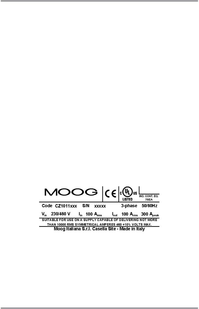
1.8SERIAL NUMBER – NAMEPLATE
Each drive is provided with a serial number identifying the Model, any eventual option and the manufacturing date. This number is a useful tool to verify, through the Moog Database, the original software and firmware revision.
Using these data it is possible to carefully support the final Customers. It is recommended to take note of the serial number, which is present on each drive, before shipment.
CODE: |
CZxxxxYYz |
Product code |
||
S/N: |
AASSNNNNYYA |
Serial number, where |
||
|
|
|
AA= year, SS= week, NNNN= progressive number, |
|
|
|
|
YYA= option (C0A= standard version) |
|
Vin: |
xxx V |
Input voltage rating |
||
Iin: |
xxx Arms |
Nominal effective input current |
||
Iout: |
xxx Arms |
Nominal effective output current |
||
Iout: |
xxx Apeak |
Output peak max current |
||
|
|
|
|
|
|
|
|
|
|
Fig. 1.2 – Nameplate
DS2000 USER’S MANUAL (rev.C)

1.10 |
SECTION ONE – DESCRIPTION |
THIS PAGE INTENTIONALLY BLANK
DS2000 USER’S MANUAL (rev.C)

SECTION TWO – WIRING AND INSTALLATION |
2.1 |
2.GENERAL INFORMATION
2.1INTRODUCTION
This section describes the installation, wiring and cabling of the Moog DS2000 servo drive series. Such information allows the understanding of DS2000 functionality and makes clear the necessary concepts to access the following sections.
DS2000 USER’S MANUAL (rev.C)

2.2 |
SECTION TWO – WIRING AND INSTALLATION |
2.2 DIMENSIONS AND DRILLING JIG
Fig. 2.1 – Size A dimensions and drilling jig (mm)
DS2000 USER’S MANUAL (rev.C)
 Loading...