


Mitsubishi PLFY-P32VKM, PLFY-P40VKM, PLFY-P50VKM, PLFY-P63VKM, PLFY-P80VKM SERVICE MANUAL
...1998
SPLIT-TYPE,HEAT PUMP AIR CONDITIONERS
No. OC158
TECHNICAL & SERVICE MANUAL
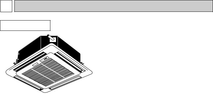
Series PLFY Ceiling Cassettes R407C
Indoor unit
[Model names] |
[Service Ref.] |
PLFY-P32VKM PLFY-P40VKM PLFY-P50VKM PLFY-P63VKM PLFY-P80VKM PLFY-P100VKM PLFY-P125VKM
PLFY-P32VKM PLFY-P40VKM PLFY-P50VKM PLFY-P63VKM PLFY-P80VKM PLFY-P100VKM PLFY-P125VKM
|
CONTENTS |
|
|
1. |
FEATURES ·········································2 |
|
2. SAFETY PRECAUTION ·····················4 |
|
|
3. PART NAMES AND FUNCTIONS······7 |
|
|
4. |
SPECIFICATION·································9 |
|
5. OUTLINES AND DIMENSIONS········11 |
|
|
6. WIRING DIAGRAM···························14 |
|
|
7. REFRIGERANT SYSTEM DIAGRAM ·15 |
|
|
8. TROUBLE SHOOTING·····················16 |
|
|
9. DISASSEMBLY PROCEDURE·········21 |
|
INDOOR UNIT |
10 . PARTS LIST ·····································24 |
|
The Slim Line.
From Mitsubishi Electric.
1 FEATURES
Series PLFY Ceiling Cassettes
Indoor unit
Models |
|
|
Cooling capacity/Heating capacity |
|
|
|
|
|
|
|
|
W |
|
kcal/h |
|||
|
|
||||
|
|
|
|
|
|
P L F Y- P 3 2 V K M |
3,700 |
/ |
4,100 |
3,150 |
/ 3,550 |
P L F Y- P 4 0 V K M |
4,700 |
/ |
5,200 |
4,000 |
/ 4,500 |
P L F Y- P 5 0 V K M |
5,800 |
/ |
6,600 |
5,000 |
/ 5,600 |
P L F Y- P 6 3 V K M |
7,300 |
/ |
8,300 |
6,300 |
/ 7,100 |
P L F Y- P 8 0 V K M |
9,300 / 10,500 |
8,000 |
/ 9,000 |
||
P L F Y- P 1 0 0 V K M |
11,600 / 13,000 |
10,000 / 11,200 |
|||
P L F Y- P 1 2 5 V K M |
14,500 |
/ |
16,300 |
12,500 |
/ 14,000 |
|
|
|
|
|
|
1.PURSUING CONPACTNESS
(1)Panel size and body volume reduced to 64% of previous models
The width and depth of the panel have been reduced by 19cm respectively,resulting in a compact model which fits smaller environments (like shops) perfectly.
(2)Multi-application panels flexibly adapt to installation conditions.
Space panel and Wide panel may be installed on ceilings with shallow depth using the exiting opening .
2."SMUDGE-FREE", PRECISELY TARGETED AIRFLOW SYSTEM
The new control system regulates airflow to prevent smudging. A projection inside the air passage distributes air evenly over the top and bottom of the vane. Two projections on the air outlet work to prevent cooled air from rising to the celling, and also to stop outside air being dragged into the cooled air stream.
3.AIRFLOW ADJUSTABLE TO ANY INDOOR ENVIRONMENT
Airflow can be adjusted according to celling height and the number of air outlets. "Wide Zoming Flow" creates anoptimum airflow for any indoor environment.
4.A FURTHER REFINEMENT OF COMFORT WITH NOISE SUPPRESION
The celling 4-way airflow cassette has a special "silent-design". The "2-Tap"system allows a choice between silent and standard modes according to the height of the cellig. For ordinary residenced which have a low celling, selection of the silent mode will result in remarkable noise reductions.
5.ECONOMICAL AND EASY MAINTENANCE
(1)Push-open grill
Filter clogging is widely recognized as a cause of reduced perfomance, but up until now it has been troublesome to clean filters. With the "push-open grill" the fillter can be smoothly opened out at the push of a button, enabling speedy cleaning.
(2)An unprecedented level of vane-cleaning
The unique airflow system prevents the intake of indoor air. Dewing therefore does not occur, and the vane is flockless. The resulting level of dirt on the vane due to tobacco smoke, dust, etc. is very light,and can be wiped off easily with a neutral detergent
(3)Long-life fillter
This new celling 4-way airflow cassette employs a long life fillter which requires no maintenance for up to 2,500 hours of operation in general office environments. It adds uo to an ideal blend of comfort and low maintenance.
2
6.COMPACT DIMENSIONS MEAN EASY INSTALLATION
(1)Carefree suspension work with lightweight unit
The new unit weighs in at 20kg (9kg lighter than the previous model) and is easy to handle and install. What's more, suspension work is facillitated by compact dimensions ensuring a snug fit.
(2)Smooth installation with "one-direction"bolts
Suspension bolts can be fixes consistently from one direction easing suspension work.
(3)Trouble-free fitting work with slender refrigerant piping
Refrigerant piping has been reduced in size, and pipe-curving work at the installation site can now be completed quickly and economically. In addition, refrigerant and drain piping are set at different corners, which means that flare connections and drain piping heat insulation work can be smoothly and reliably implemented.
(4)Easy-access terminal and control panels for efficient wiring
When performing wiring work, progress can be checked on the power source terminal and control panels simply by removing the electrical parts cover. Adress setting can also be done easily from beneath at a convenient angle.
(5)"One-push"to provisionally position front panel
Panel weight has been redused from 7kg to 3.7kg. The previous 3-step process for provisionally positioning the panel has been streamlined, and now a simple "one-push" action at the diagonal corners fixed it into place, resulting in major
time-saving.
7.ADVANCED MICROPROCESSOR [PAR-F25MA]
(1)Easy to use microprocessor 1)Ultra-thin remote controller
The streamlind,square controller is designed to blend well with any interior.Also,the sophisticated microprocessor allows you to easily carry out a wide range of operations.
2)Attractive liquid crystal display(LCD)
The unit´s operation mode,set temperature,room temperature,timer setting,fan speed,louver oper-ation,and air flow direction are displayed on the remote controller´s easy-to-read Liquid Crystal Dis-play(LCD).
3)Convenient 24-hour ON-OFF timer
The timer switches Mr.SLIM on and off automati-cally at the time you set. Once the timer is set,the remaining time is shown on the LCD
3

2 SAFETY PRECAUTION
Cautions for devices that use R407C refrigerant.
·Do not use the existing refrigerant piping.
-The old refrigerant and refrigerator oil in the existing piping contains a large amount of chlorine which may cause the refrigerator oil of the new unit to deteriorate.
·Use “low residual oil piping”.
-If there is a large amount of residual oil (hydraulic oil, etc.) inside the piping and joints, deterioration of the refrigerator oil will result.
·Store the piping to be used during installation indoors and keep both ends of the piping sealed until just before brazing. (Store elbows and other joints in a plastic bag.)
-If dust, dirt, or water enters the refrigerant cycle, deterioration of the oil and compressor trouble may result.
·Use Suniso 4GS or 3GS (small amount) as the refrigerator oil to coat flares and flange connection parts.
-The refrigerator oil used with the air conditioner is highly hygroscopic. If it is used, water may be mixed in and deterioration of the refrigerator oil may result.
·Use liquid refrigerant to seal the system.
-If gas refrigerant is used to seal the system, the composition of the refrigerant in the cylinder will change and performance may drop.
·Do not use a refrigerant other than R407.
-If another refrigerant (R22, etc.) is used, the chlorine in the refrigerant may cause the refrigerator oil to deteriorate.
·Use a vacuum pump with a reverse flow check valve.
-The vacuum pump oil may flow back into the refrigerant cycle and cause the refrigerator oil to deteriorate.
4

[1] Service tools
Use the below service tools as exclusive tools for R407C refrigerant.
No. |
Tool name |
Specifications |
|
1 |
Gauge manifold |
·Only for R407C. |
|
|
|
·Use the existing fitting SPECIFICATIONS. (UNF7/16) |
|
|
|
·Use high-tension side pressure of 35kgf/cm or over. |
|
|
|
2 |
|
2 |
Charge hose |
·Only for R407C. |
|
|
|
·Use pressure performance of 52kgf/cm or over. |
|
3 |
Electronic scale |
|
|
4 |
Gas leak detector |
·Use the detector for R134a or R407C. |
|
5 |
Adapter for reverse flow check. |
·Attach on vacuum pump. |
|
6 |
Refrigerant charge base. |
|
|
7 |
Refrigerant cylinder. |
·For R407C ·Top of cylinder (Brown) |
|
|
|
·Cylinder with syphon |
|
8 |
Refrigerant recovery equipment. |
|
|
[2] Notice on repair service
·After recovering the all refrigerator in the unit, proceed to working. ·Do not release the refrigerant in the air.
·After complete the repair service, recharge the cycle with the specified amount of the liquid refrigerant.
5
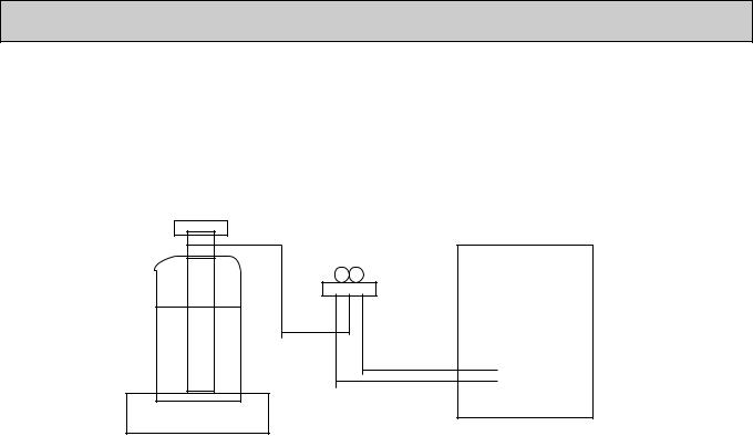
[3]Refrigerant recharging
(1)Refrigerant recharging process
1Direct enclosure from the bomb.
·Comfirm that R407C bomb on the market are syphon pipe.
·Leave the syphon pipe bomb raising and recharge it.
(By liquid refrigerant)
Unit
Gravimeter
(2) Recharge in refrigerant leakage case
·After recovering the all refrigerator in the unit, proceed to working.
·Do not release the refrigerant in the air.
·After complete the repair service, recharge the cycle with the specified amount of the liquid refrigerant.
6

3 
 PART NAMES AND FUNCTIONS
● Indoor (Main) Unit
Filters
Remove dust and pollutants from inhaled air
Horizontal Air Outlet
Sets airflow horizontal automatically during cooling or dehumidifying.
Grill
Auto Air Swing Vane Disperses airflow up and down and adjusts the angle of airflow direction.
Air Intake
Inhales air from room.
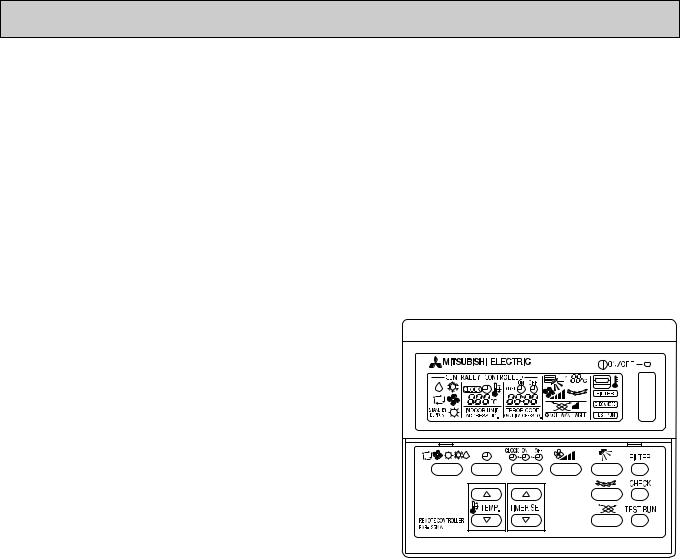
● Remote controller |
[PAR-F25MA] |
|
● Once the controls are set, the same operation mode can |
|
be repeated by simply pressing the ON/OFF button. |
● Operation buttons |
|
|
|
|
|
|
|
|
|
|
|
|
TIMER button |
|
TIME SETTING button |
|
AIR SPEED button |
|
This switches between continuous |
|
This sets of switches the current time. |
|
This sets the ventilation fan speed. |
|
operation and the timer operation. |
|
start time and stop time. |
|
|
|
|
|
|
||
|
|
|
|
|
|
OPERATION SWITCH button |
ON/OFF button |
Press this button to switch the cooler |
This swiches between the operation |
electronic dry (dehumidify) automatic and |
and stop modes each time it is |
heater modes. |
pressed. The lamp on this button |
|
lights during operation. |
|
AIR DIRECTION button |
TEMP ADJUSTMENT button |
This adjusts the vertical angle of the |
ventilation. |
|
This sets the room temparature The |
|
temparature setting can be performed in 1°C |
FILTER button |
units |
|
Setting range |
This resets the filter service indication |
Cooler 19°C to 30°C |
display. |
LOUVER button |
CHECK-TEST RUN button |
This switches the horizontal fan |
Only press this button to perform an |
motion ON and OFF. |
inspection check or test operation Do |
(This button does not operate in this |
not use it for nomal operation. |
|
|
model) |
|
7

● Display
CENTRALLY CONTROLLED display
This indicates when the unit is controlled by optional features such as central control type remote controller.
TIMER display
This indicates when the continous operation and time operation modes are set.
It also display the time for the timer operation at the same time as when it is set.
OPERATION MODE display
This indicates the operation mode.
STANDBY display
This indicates when the standby mode is set from the time the sleep operation starts until the heating air is discharged.
DEFROST display
This indicates when the defrost operation is performed.
CLOCK display |
In this display example on the |
|
bottom left, a condition where all |
||
|
||
The current time , start time and stop |
display lamps light is shown for |
|
time can be displayed in tensecond |
explanation purposes although this |
|
intervals by pressing the time switch |
differs from actual operation. |
|
button. The start time or stop time is |
||
|
||
always displayed during the timer |
|
|
operation. |
|
|
|
AIR DIRECTION display |
|
|
The selected fan speed is displayed. |
|
|
FAN SPEED display |
|
|
This displays the air direction. |
|
|
ROOM TEMPERATURE display |
|
|
The temperature of the suction air is |
|
|
displayed during operation. The |
|
|
display range is 8° to 39°C. The |
|
|
display flashes 8°C when the actual |
|
|
temperature is less than 8° and |
|
|
flashes 39°C when the actual |
|
|
temperature is greater than 39°C. |
|
|
Operation lamp |
|
4 |
This lamp lights during operation, |
|
|
goes off when the unit stops and |
|
|
flashes when amalfunction occurs. |
|
|
CHECK MODE |
|
|
display |
|
|
TEST RUN |
|
|
This display lights in the check mode |
|
|
or when a test operation is |
|
|
performed. |
CHECK display |
|
|
|
|
This indicates when a malfunction |
|
SET TEMPERATURE display |
|
POWER display |
|
|
|
|
|
has occurred in the unit which should |
|
This displays the selected setting |
|
This lamp lights when electricity is |
be checked. |
|
|
||
|
temperature. |
|
supplied to the unit. |
|
|
|
|
||
|
|
|
|
|
Caution
FILTER display
This lamp lights when the filter need to be cleaned.
●Only the Power display lights when the unit is stopped and power supplied to the unit.
●When power is turned ON for the first time the (CENTRAL CTRL) display appears to go off momentarily but this is not a malfunction.
●When the central control remote control unit, which is sold separately, is used the ON-OFF button, operation switch button and  TEMP adjustment button do not operate.
●“NOT AVAILABLE” is displayed when the Air speed button are pressed.This indicates that this room unit is not equipped with the fan direction adjustment function and the louver function.
●When power is turned ON for the first time, it is normal that “H0” is displayed on the room temperature indication (For max. 2minutes). Please wait until this “H0” indication disappear then start the operation.
8
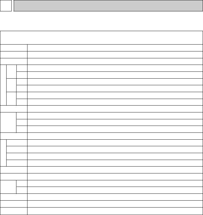
4 SPECIFICATION
4-1. Specification
Item
Power
Cooling capacity
Heating capacity
charocteristic |
Power |
Cooling |
|
supply Heating |
|||
|
|||
|
Starting Cooling |
||
|
current |
Heating |
|
Electric |
|
||
factor |
Heating |
||
|
Power |
Cooling |
|
Exteior (munsell symbol)
|
Height |
|
Out |
Width |
|
dimensions |
||
|
||
|
Depth |
Heat exchanger
|
Fan x No |
|
F |
Air flow #3 |
|
a |
External |
|
n |
||
static pressure |
||
|
Fan motor |
|
|
Output |
|
|
Insulator |
Air filter
Gas Pipe side dimensions Liquid side
Drain pipe size
Noise level
Product weight
|
PLFY-P32VKM |
PLFY-P40VKM |
|
PLFY-P50VKM |
|
PLFY-P63VKM |
|
PLFY-P80VKM |
PLFY-P100VKM |
PLFY-P125VKM |
|||
|
|
|
|
|
|
|
|
|
|
|
|
|
|
V•Hz |
|
|
|
|
Single phase 220V-240V 50 HZ |
|
|
|
|
||||
kcal/h |
3,150 |
|
|
|
5,000 |
|
6,300 |
|
8,000 |
|
10,000 |
|
12,500 |
4,000 |
|
|
|
|
|
|
|||||||
kcal/h |
3,550 |
4,500 |
|
|
5,600 |
|
7,100 |
|
9,000 |
|
11,200 |
|
14,000 |
kw |
0.13 |
0.13 |
|
|
0.14 |
|
0.15 |
|
0.17 |
|
0.21 |
|
0.22 |
kW |
0.13 |
0.13 |
|
|
0.14 |
|
0.15 |
|
0.17 |
|
0.21 |
|
0.22 |
A |
0.60 |
0.60 |
|
|
0.64 |
|
0.68 |
|
0.77 |
|
0.95 |
|
1.00 |
A |
0.60 |
0.60 |
|
|
0.64 |
|
0.68 |
|
0.77 |
|
0.95 |
|
1.00 |
% |
- |
- |
|
|
- |
|
- |
|
- |
|
- |
|
- |
% |
- |
- |
|
|
- |
|
- |
|
- |
|
- |
|
- |
|
|
|
|
|
|
|
|
|
|
|
|
|
|
|
-Unit: Galranized sheets |
• Standard grill:ABS tesin acrylic coating |
Munsell<0.70Y 8.59/0.97> |
||||||||||
mm |
|
298<30> |
|
|
|
|
297<30> |
|
|
||||
|
|
|
|
|
|
|
|||||||
mm |
|
660<760> |
|
|
|
|
840<950> |
|
|
||||
mm |
|
660<760> |
|
|
|
840<950> |
|
1360<1470> |
|||||
|
|
|
|
|
|||||||||
- |
|
|
|
|
|
|
Cross fin |
|
|
|
|
|
|
|
|
|
|
|
|
|
|
|
|
|
|
||
|
|
|
|
|
|
|
Turbo fan x 1 |
|
|
|
|
|
|
|
|
|
|
|
|
||||||||
k/min |
15-14.5-14-13 |
|
16-15-14-13 |
|
17-16-15-14 |
|
22-20-18-16.5 |
26-24-21.5-19.5 |
30-27.5-25-22.5 |
||||
Pa |
|
|
|
|
|
0 |
|
|
|
|
|
|
|
kW |
|
|
|
|
|
|
|
|
|
0.090 |
|
|
|
|
|
|
|
|
|
|
|
|
|
|
|
||
|
|
|
|
|
Polyethylene sheet |
|
|
|
|
||||
|
|
|
|
|
PP honey comb |
|
|
|
|
||||
[mm |
|
12.7<1/2”> |
|
|
|
|
15.88<5/8”> |
|
|
|
19.05<3/4”> |
||
|
|
|
|
|
|
|
|
||||||
[mm |
|
6.35<1/4”> |
|
|
|
|
9.52<3/8”> |
|
|
|
9.52<3/8”> |
|
|
[mm |
|
|
|
|
PVC pipe VP-25 connectable |
|
|
|
|
||||
|
|
|
|
|
|
||||||||
dB(A) |
35-34-32.5-31 |
|
37-35.5-34-32 |
|
39-38-36.5-35 |
|
38-35-32-30 |
|
42-39-36-34 |
||||
kg |
|
19<3.7> |
|
|
|
|
20<3.7> |
|
28<5> |
|
29<5> |
|
37<9> |
|
|
|
|
|
|
|
|
||||||
|
|
|
|
|
|
|
|
|
|
|
|
|
|
Note 1. Rating conditions(JIS B 8616)
Cooling: Indoor: 27°C DB. 19.5°CWB outdoor: 35°C DB.
Heating: Indoor: 21°CDB
outdoor: 7°CDB. 6°CWB Note 2. The number indicated in < > is just for the grill.
Note 3. Air flow and the noise level are indicated as High-Middium 1-Middium 2-Low.
9
4-2. Electrical parts specifications
Model
Symbol PLFY-P32VKM PLFY-P40VKM PLFY-P50VKM PLFY-P63VKM PLFY-P80VKM PLFY-P100VKM PLFY-P125VKM
Parts
name
Tranrsformer |
T |
|
Room temperature |
TH21 |
|
thermistor |
||
|
||
Liquid pipe thermistor |
TH22 |
|
Gas pipe thermistor |
TH23 |
|
Fuse |
FUSE |
|
(Indoor controller board) |
|
|
Fan motor |
MF |
|
(with Inner-thermostat) |
|
|
Inner-thermostat |
|
|
(Fan motor) |
|
|
Fan motor capacitor |
C1 |
|
Vane motor |
MV |
|
(with limit switch) |
|
|
Drain-up mechanism |
DP |
|
Drain sensor |
DS |
|
Linear expansion valve |
LEV |
|
Electric heater |
H2 |
|
(Condensation proof) |
|
|
Power supply terminal |
TB2 |
|
block |
||
|
||
Transmission terminal |
TB5 |
|
block |
||
|
(Primary) 50/60Hz 220-240V (Secondry) (18.4V 1.7A)
Resistance 0:/15k',10:/9.6k',20:/6.3k',25:/5.4k',30:/4.3k',40:/3.0k'
Resistance 0:/15k',10:/9.6k',20:/6.3k',25:/5.4k',30:/4.3k',40:/3.0k'
Rresistance 0:/15k',10:/9.6k',20:/6.3k',25:/5.4k',30:/4.3k',40:/3.0k'
250V |
6.3A |
6-pole OUTPUT 30W |
6-pole Output 90W |
PA1-V30F |
D17A6P90MS |
OFF 125:±5: |
OFF 130:±5: |
ON 85:±20: |
ON 90:±20: |
2+ x 400V |
4+ x 460V |
MC8 200V-240V 2.5/2W 5/6R.P.M
PCD-4N230ME
INPUT 17/15W 36R/Hr
Heater resistance 82'/25:
Thermistor resistance 0:/15k',10:/9.6k',20:/6.3k',25:/5.4k',30:/4.3k',40:/3.0k'
DC12V Stepping motor drive port |
|
DC12V Stepping motor drive |
dimension 3.2 ' (0~2000pulse) |
|
port dimension 5.2 ' (0~2000pulse) |
EDM-402ME |
|
EDM-804ME |
|
|
|
240V 28.8W |
|
|
(L,N,;) 330V 30A
(M1,M2,S) 330V 30A
10
11
|
|
25~35 |
|
Ceiling hole |
25~35 |
|
|
|
|
690~710 |
|||
|
|
|
|
|
|
|
|
|
|
|
640 |
|
|
|
|
|
Suspension bolt pitch |
|
117 |
|
25~35 |
|
|
|
|
|
|
|
|
Terminal block for |
|
117 |
||
|
|
|
|
|
||
Ceilinghole 690~710 |
|
Suspensionbolt pitch |
power supply |
|
|
|
507 |
Terminal block for control |
660 |
||||
|
|
|
|
|||
|
|
|
|
Drain hole |
|
|
25~35 |
77 |
64 |
186 |
68 |
117 |
13 117 |
|
|
|
660 |
|
||
|
|
|
|
|
Drain pipe |
|
|
|
|
|
|
|
|
NOTE 1.The electrical parts box may be removed during servic-
ing.When connecting the power line and the control wire,provide enough length to the electric wires.
NOTE 2.When installing the optional high-efficiency filter,the dimension between the transom and ceiling shall be more than 440mm. Also,when installing the optional
fresh air intake casement or the multi-functional casement,the dimension between the transom and ceiling shall be more than 440mm. (The optional highefficiency filter can also be installed.)
Optional high-efficiency filter |
135 |
435 |
|
|
Suspension bolt M10 |
75 |
65 |
2 |
|||
1 |
||||||
or W3/8 |
|
|
|
|
||
166 |
156 |
65~80 |
|
|
|
|
Suspension bolt lower edge |
|
|
|
|||
Control wire entry |
|
|
||||
|
|
|
Power line entry |
|||
Refrigerant piping side |
|
466 |
||||
|
|
|||||
electric wire entry side |
|
Air intake hole |
||||
|
|
A |
|
|
|
|
760 |
|
460 |
outlet hole |
|
|
|
|
|
|
Air |
|
|
|
|
|
66 |
|
|
|
|
|
|
35 |
|
|
460 |
|
|
|
|
|
|
||
|
Air intake grill |
|
Air outlet hole |
|||
|
|
|
|
|
760 |
|
VP-25 connection
42
Feeding hole (Drain pump)
115 |
243 |
253 |
298 |
Leave space of 10~15mm between the |
|
|
|
|
top surface of the unit and the ceiling slab |
Ceiling surface |
+3 |
-2 |
30 |
|
54 |
|
|||
|
|
|
|
|
Grill
Vane motor
|
4-Auto vanes |
|
|
|
hole |
Models |
1 |
|
466 intake |
||
|
PLFY-32VKM |
Refrigerant pipe |
|
|
|
||
|
|
(6.35mmdia) |
|
|
Air |
PLFY-40VKM |
flared connection |
|
|
1/4F |
|
|
|
|
|
|
|
PLFY-P50VKM |
Refrigerant pipe |
|
|
(9.52mmdia) |
|
|
|
PLFY-P63VKM |
flared connection |
|
Intake grill opening/closing side |
|
3/8F |
66 |
35 |
|
|
+3 54 -2
2
Refrigerant pipe (12.7mmdia) flared connection 1/2F
Refrigerant pipe (15.88mmdia) flared connection 5/8F
P40VKM-P32VKM,PLFY-PLFY
P63VKM-P50VKM,PLFY-PLFY
mm : Unit
DIMENSIONS AND OUTLINES 5
 Loading...