


SPLIT-TYPE, HEAT PUMP AIR CONDITIONERS
July 2006
No. OC356
REVISED EDITION-A
TECHNICAL & SERVICE MANUAL
|
|
|
|
|
|
|
|
|
|
|
|
|
|
|
|
|
|
|
|
|
|
|
|
|
|
|
<Indoor unit> |
|
|
|
|
|
|
|
|
[Model names] |
[Service Ref.] |
|||||||
PKFY-P63VFM-E |
PKFY-P63VFM-E |
|||||||
PKFY-P100VFM-E |
PKFY-P100VFM-E |
|||||||
Revision:
•RoHS PARTS LIST is added.
•Some descriptions have been modified.
•Please void OC356.
Note:
•This manual describes only service data of the indoor units.
•RoHS compliant products have <G> mark on the spec name plate.
•For servicing of RoHS compliant products, refer to the RoHS Parts List.
CONTENTS
|
1. SAFETY PRECAUTION············ |
|
2. PART NAMES AND FUNCTIONS ········ |
|
3. SPECIFICATIONS··············· |
|
4. OUTLINES AND DIMENSIONS ········· |
|
5. WIRING DIAGRAM ·············· |
|
6. REFRIGERANT SYSTEM DIAGRAM ····14 |
|
7. TROUBLE SHOOTING ············ |
Indoor unit |
8. DISASSEMBLY PROCEDURE ········· |
|
9. PARTS LIST················· |
|
10. RoHS PARTS LIST ·············· |
1 
 SAFETY PRECAUTION
CAUTIONS RELATED TO NEW REFRIGERANT
Cautions for units utilizing refrigerant R407C
Do not use the existing refrigerant piping.
The old refrigerant and lubricant in the existing piping contains a large amount of chlorine which may cause the lubricant deterioration of the new unit.
Use liquid refrigerant to seal the system.
If gas refrigerant is used to seal the system, the composition of the refrigerant in the cylinder will change and performance may drop.
Use “low residual oil piping”
If there is a large amount of residual oil (hydraulic oil, etc.) inside the piping and joints, deterioration of the lubricant will result.
Store the piping to be used during installation indoors with keep both ends sealed until just before brazing.
(Store elbows and other joints in a plastic bag.)
If dust, dirt, or water enters the refrigerant cycle, deterioration of the oil and compressor trouble may result.
Use ESTR , ETHER or HAB as the lubricant to coat flares and flange connection parts.
If large amount of mineral oil enter, that can cause deterioration of refrigerant oil etc.
Do not use a refrigerant other than R407C.
If another refrigerant (R22, etc.) is used, the chlorine in the refrigerant may cause the lubricant deterioration.
Use a vacuum pump with a reverse flow check valve.
The vacuum pump oil may flow back into the refrigerant cycle and cause the lubricant deterioration.
Ventilate the room if refrigerant leaks during operation. If refrigerant comes into contact with a flame, poisonous gases will be released.
[1] Cautions for service
·After recovering the all refrigerant in the unit, proceed to working. ·Do not release refrigerant in the air.
·After completing the repair service, recharge the cycle with the specified amount of liquid refrigerant.
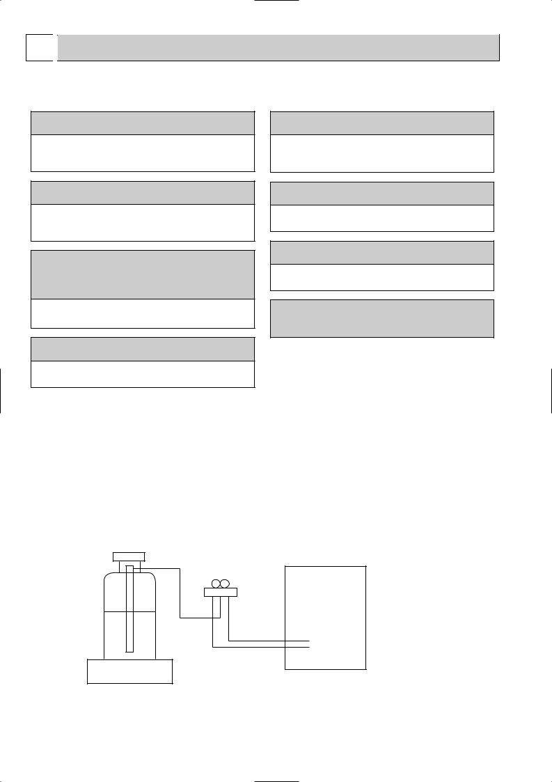
[2] Refrigerant recharging
(1) Refrigerant recharging process
1Direct charging from the cylinder.
·R407C cylinder are available on the market has a syphon pipe. ·Leave the syphon pipe cylinder standing and recharge it.
(By liquid refrigerant)
Unit
Gravimeter
(2) Recharge in refrigerant leakage case
·After recovering the all refrigerant in the unit, proceed to working. ·Do not release the refrigerant in the air.
·After completing the repair service, recharge the cycle with the specified amount of liquid refrigerant.
2

[3] Service tools
Use the below service tools as exclusive tools for R407C refrigerant.
No. |
Tool name |
Specifications |
|
|
|
|
|
1 |
Gauge manifold |
·Only for R407C. |
|
|
|
|
|
|
|
·Use the existing fitting SPECIFICATIONS. (UNF7/16) |
|
|
|
|
|
|
|
·Use high-tension side pressure of 3.43MPa·G or over. |
|
|
|
|
|
2 |
Charge hose |
·Only for R407C. |
|
|
|
|
|
|
|
·Use pressure performance of 5.10MPa·G or over. |
|
|
|
|
|
3 |
Electronic scale |
|
— |
|
|
|
|
4 |
Gas leak detector |
·Use the detector for R134a or R407C. |
|
|
|
|
|
5 |
Adapter for reverse flow check. |
·Attach on vacuum pump. |
|
|
|
|
|
6 |
Refrigerant charge base. |
|
— |
|
|
|
|
7 |
Refrigerant cylinder. |
·For R407C |
·Top of cylinder (Brown) |
|
|
·Cylinder with syphon |
|
|
|
|
|
8 |
Refrigerant recovery equipment. |
|
— |
|
|
|
|
3

Cautions for units utilizing refrigerant R410A
Do not use the existing refrigerant piping.
The old refrigerant and lubricant in the existing piping contains a large amount of chlorine which may cause the lubricant deterioration of the new unit.
Use “low residual oil piping”
If there is a large amount of residual oil (hydraulic oil, etc.) inside the piping and joints, deterioration of the lubricant will result.
Store the piping to be used during installation indoors and keep both ends of the piping sealed until just before brazing. (Leave elbow joints, etc. in their packaging.)
If dirt, dust or moisture enter into refrigerant cycle, that can cause deterioration of refrigerant oil or malfunction of compressor.
Use ester oil, ether oil or alkylbenzene oil (small amount) as the refrigerant oil applied to flares and flange connections.
If large amount of mineral oil enter, that can cause deterioration of refrigerant oil etc.
Charge refrigerant from liquid phase of gas cylinder.
If the refrigerant is charged from gas phase, composition change may occur in refrigerant and the efficiency will be lowered.
Do not use refrigerant other than R410A.
If other refrigerant (R22 etc.) is used, chlorine in refrigerant can cause deterioration of refrigerant oil etc.
Use a vacuum pump with a reverse flow check valve.
Vacuum pump oil may flow back into refrigerant cycle and that can cause deterioration of refrigerant oil etc.
Use the following tools specifically designed for use with R410A refrigerant.
The following tools are necessary to use R410A refrigerant.
|
Tools for R410A |
|
Gauge manifold |
|
Flare tool |
Charge hose |
|
Size adjustment gauge |
Gas leak detector |
|
Vacuum pump adaptor |
Torque wrench |
|
Electronic refrigerant |
|
|
charging scale |
|
|
|
Keep the tools with care.
If dirt, dust or moisture enter into refrigerant cycle, that can cause deterioration of refrigerant oil or malfunction of compressor.
Do not use a charging cylinder.
If a charging cylinder is used, the composition of refrigerant will change and the efficiency will be lowered.
Ventilate the room if refrigerant leaks during operation. If refrigerant comes into contact with a flame, poisonous gases will be released.
4

[1]Cautions for service
(1)Perform service after collecting the refrigerant left in unit completely.
(2)Do not release refrigerant in the air.
(3)After completing service, charge the cycle with specified amount of refrigerant.
(4)When performing service, install a filter drier simultaneously. Be sure to use a filter drier for new refrigerant.
[2]Additional refrigerant charge
When charging directly from cylinder
·Check that cylinder for R410A on the market is syphon type.
·Charging should be performed with the cylinder of syphon stood vertically. (Refrigerant is charged from liquid phase.)
Unit
Gravimeter
[3] Service tools
Use the below service tools as exclusive tools for R410A refrigerant.
No. |
|
Specifications |
1 |
Gauge manifold |
·Only for R410A |
|
|
|
|
|
·Use the existing fitting specifications. (UNF1/2) |
|
|
|
|
|
·Use high-tension side pressure of 5.3MPa·G or over. |
|
|
|
2 |
Charge hose |
·Only for R410A |
|
|
|
|
|
·Use pressure performance of 5.09MPa·G or over. |
3Electronic scale
4 |
Gas leak detector |
·Use the detector for R134a, R407C or R410A. |
|
|
|
5 |
Adaptor for reverse flow check |
·Attach on vacuum pump. |
6Refrigerant charge base
7 Refrigerant cylinder |
·Only for R410A |
Top of cylinder (Pink) |
|
|
Cylinder with syphon |
8Refrigerant recovery equipment
5
2 
 PART NAMES AND FUNCTIONS
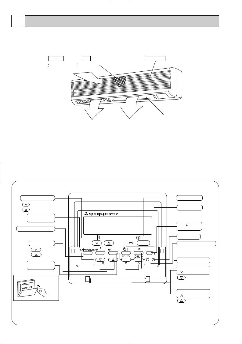
● Indoor Unit
PKFY-P63VFM-E PKFY-P100VFM-E
Air intake |
Filter |
Air intake grille |
Room air is suctioned |
(Removes dust and dirt from the intake air.) |
in here. |
|
Guide vane |
|
|
|
Auto vane |
||
|
|
|
|
|
|
|
Air flow can be changed to horizontally |
|
|
|
|||
by moving the Guide vane to the left or |
|
|
|
|||
right. |
|
|
|
|||
|
|
|
|
|
|
|
|
|
Air outlet |
|
Air outlet |
|
|
|
|
|
|
|
|
|
● Wired remote controller
On the controls are set, the same operation mode can be repeated by simply pressing the ON/OFF button.
● Operation buttons
Set Temperature buttons |
|
|
|
Down |
|
|
|
Up |
|
|
|
Timer Menu button |
|
|
|
(Monitor/Set button) |
|
|
|
Mode button (Return button) |
|
|
|
|
|
TEMP. |
|
Set Time buttons |
|
|
|
Back |
|
MENU |
ON/OFF |
Ahead |
BACK |
MONITOR/SET |
DAY |
|
|||
Timer On/Off button |
PAR-21MAA |
CLOCK |
|
(Set Day button) |
|
|
|
Opening the |
|
|
|
door. |
|
|
|
|
|
ON/OFF button |
||
|
|
Fan Speed button |
||
|
|
Filter |
button |
|
|
|
(<Enter> button) |
||
|
ON/OFF |
Test Run button |
||
|
|
|
|
|
|
|
Check button (Clear button) |
||
|
FILTER |
|
|
|
|
CHECK |
TEST |
|
|
OPERATION |
|
Airflow Up/Down button |
||
CLEAR |
|
|
|
|
|
|
Louver button |
||
|
|
( |
|
Operation button) |
|
|
|
|
To preceding operation |
|
|
|
|
number. |
|
|
Ventilation button |
||
|
|
( |
Operation button) |
|
|
|
|
|
To next operation number. |
6

● Display
For purposes of this explanation, all parts of the display are shown as lit. During actual operation, only the relevant items will be lit.
Identifies the current operation
Shows the operating mode, etc.
*Multilanguage display is supported.
“Centrally Controlled” indicator
Indicates that operation of the remote controller has been prohibited by a master controller.
“Timer Is Off” indicator
Indicates that the timer is off.
Temperature Setting
Shows the target temperature.
Day-of-Week
Shows the current day of the week.
Time/Timer Display
Shows the current time, unless the simple or Auto Off timer is set.
If the simple or Auto Off timer is set, shows the time remaining.
TIME SUN MON TUE WED THU FRI SAT |
||
TIMER |
Hr |
ON |
AFTER |
AFTER |
OFF |
ERROR CODE |
|
FUNCTION |
˚F˚C |
|
FILTER |
˚F˚C |
|
|
|
WEEKLY |
|
ONLY1Hr. |
|
SIMPLE |
|
AUTO OFF |
|
Up/Down Air Direction indicator
The indicator  shows the direction of the outcoming airflow.
“One Hour Only” indicator
Displayed if the airflow is set to weak and downward during COOL or DRY mode. (Operation varies according to model.)
The indicator goes off after one hour, at which time the airflow direction also changes.
Room Temperature display
Shows the room temperature.
Louver display
Indicates the action of the swing louver. Does not appear if the louver is stationary.
 (Power On indicator)
Indicates that the power is on.
“Sensor” indication
Displayed when the remote controller sensor is used.
“Locked” indicator
Indicates that remote controller buttons have been locked.
“Clean The Filter” indicator
Comes on when it is time to clean the filter.
Timer indicators
The indicator comes on if the corresponding timer is set.
Fan Speed indicator
Shows the selected fan speed.
Ventilation indicator
Appears when the unit is running in Ventilation mode.
Caution
●Only the Power on indicator lights when the unit is stopped and power supplied to the unit.
●If you press a button for a feature that is not installed at the indoor unit, the remote controller will display the “Not Available” message.
If you are using the remote controller to drive multiple indoor units, this message will appear only if he feature is not present at the parent unit.
●When power is turned ON for the first time, it is normal that “PLEASE WAIT” is displayed on the room temperature indication (For max. 2minutes). Please wait until this “PLEASE WAIT” indication disappear then start the operation.
7

3 |
|
SPECIFICATIONS |
|
|
|
|||
|
|
|
|
|
|
|
|
|
3-1. SPECIFICATION |
|
|
|
|
|
|||
|
|
|
|
|
|
|
||
Item |
|
|
Unit |
|
PKFY-P63VFM-E |
|
PKFY-P100VFM-E |
|
|
|
|
|
|
|
|
||
Power source |
|
[,V,Hz |
|
Single phase, 220-230-240V, 50Hz / 220V, 60Hz |
||||
|
|
|
|
|
|
|
|
|
Cooling capacity |
|
kW |
|
7.1 |
|
11.2 |
||
|
|
|
|
|
|
|
|
|
Heating capacity |
|
kW |
|
8.0 |
|
12.5 |
||
|
|
|
|
|
|
|
|
|
Electric characteristic |
Input |
Cooling |
kW |
|
0.12 |
|
0.14 |
|
|
|
|
|
|
|
|||
|
|
Heating |
kW |
|
0.12 |
|
0.14 |
|
|
|
|
|
|
||||
|
|
|
|
|
|
|
|
|
|
|
Current |
Cooling |
A |
|
0.55 |
|
0.64 |
|
|
|
|
|
|
|
|
|
|
|
Heating |
A |
|
0.55 |
|
0.64 |
|
|
|
|
|
|
||||
|
|
|
|
|
|
|
|
|
Exterior <munsell symbol> |
— |
|
Plastic |
, white : <3.4Y 7.7/0.8> |
||||
|
|
|
|
|
|
|
|
|
|
|
|
Height |
mm |
|
340 |
|
340 |
|
|
|
|
|
|
|
|
|
Dimensions |
Width |
mm |
|
1,400 |
|
1,680 |
||
|
|
|
|
|
|
|
|
|
|
|
|
Depth |
mm |
|
235 |
|
235 |
|
|
|
|
|
|
|
||
Heat exchanger |
|
— |
|
Cross fin(Aluminum plate fin and copper tube) |
||||
|
|
|
|
|
|
|
|
|
|
|
Type No. |
|
— |
|
|
Line flow fan 2 |
|
|
|
|
|
|
|
|
|
|
Fan |
Air flow High - Low |
k/min |
|
20 - 15 |
|
28 - 22 |
||
|
|
|
|
|
|
|
||
External static pressure |
Pa |
|
|
0 |
||||
|
|
|
|
|||||
|
|
|
|
|
|
|
|
|
|
|
Fan motor output |
|
kW |
|
0.04 |
|
0.07 |
|
|
|
|
|
|
|
||
Insulator |
|
— |
|
Polyethylene sheet |
||||
|
|
|
|
|
|
|
||
Air filter |
|
— |
|
PP Honeycomb fabric |
||||
|
|
|
|
|
|
|
|
|
Pipe dimensions |
Gas side |
[mm(in.) |
|
15.88(5/8") |
|
15.88(5/8") : R410A / 19.05(3/4") : R407C/ R22 |
||
|
|
|
|
|
|
|||
Liquid side |
[mm(in.) |
|
9.52(3/8") |
|
9.52(3/8") |
|||
|
|
|
|
|
||||
|
|
|
|
|
|
|
||
Drain pipe dimension |
|
[mm |
|
Drain socket (Accessory) O.D. 20 <PVC pipe VP-20 connectable> |
||||
|
|
|
|
|
|
|
|
|
Noise level High - Low |
|
dB |
|
45 - 39 |
|
46 - 41 |
||
|
|
|
|
|
|
|
|
|
Product weight |
|
kg |
|
24 |
|
28 |
||
|
|
|
|
|
|
|||
Note : Rating conditions (JIS B8616) |
|
|
|
|
|
|||
|
|
Cooling : Indoor |
D.B. 27°C |
W.B. 19.0°C |
|
|
||
|
|
Outdoor D.B. 35°C |
W.B. 24°C |
|
|
|
||
|
|
Heating : Indoor |
D.B. 20°C |
|
|
|
|
|
|
|
Outdoor D.B. 7°C |
W.B. 6°C |
|
|
|
||
8
3-2. ELECTRICAL PARTS SPECIFICATIONS
Service Ref. |
Symbol |
PKFY-P63VFM-E |
|
PKFY-P100VFM-E |
|
Parts name |
|
||||
|
|
|
|
||
Room temperature thermistor |
TH21 |
Resistance 0°C/15kΩ , 10°C/9.6kΩ , 20°C/6.3kΩ , 25°C/5.2kΩ , 30°C/4.3kΩ , 40°C/3.0kΩ |
|||
Liquid pipe temperature thermistor |
TH22 |
Resistance 0°C/15kΩ , 10°C/9.6kΩ , 20°C/6.3kΩ , 25°C/5.2kΩ , 30°C/4.3kΩ , 40°C/3.0kΩ |
|||
Gas pipe temperature thermistor |
TH23 |
Resistance 0°C/15kΩ , 10°C/9.6kΩ , |
20°C/6.3kΩ , 25°C/5.2kΩ , 30°C/4.3kΩ , 40°C/3.0kΩ |
||
Fuse |
FUSE |
|
250V 6.3A |
||
(Indoor controller board) |
|
||||
|
|
|
|
||
|
|
D094P40MS |
|
D10A4P70MS |
|
Fan motor |
|
220-230-240V / 50Hz, 220V / 60Hz |
220-230-240V / 50Hz , 220V / 60Hz |
||
MF |
4pole Output 40W |
|
4pole Output 70W |
||
(with inner-thermostat) |
|
|
|
||
|
Inner-thermostat |
OFF 130±5; |
|||
|
|
||||
Fan motor capacitor |
C1 |
2.0= 440V |
|
3.0= 440V |
|
Vane motor |
MV |
MP 35 EA DC12V |
|||
Linear expansion valve |
LEV |
DC12V Stepping motor drive |
|
DC12V Stepping motor drive |
|
Port dimension [3.2 (0 ~ 2,000pulse) |
Port dimension [5.2 (0 ~ 2,000pulse) |
||||
|
|
||||
Power supply terminal block |
TB2 |
(L, N, ;) |
330V 30A |
||
Transmission terminal block |
TB5 |
(M1, M2, S) 250V 20A |
|||
MA remote controller |
TB15 |
|
(1,2) 250V 10A |
||
terminal block |
|
||||
|
|
|
|
||
Dew prevention heater |
H2 |
|
28.8W / 240V |
||
9

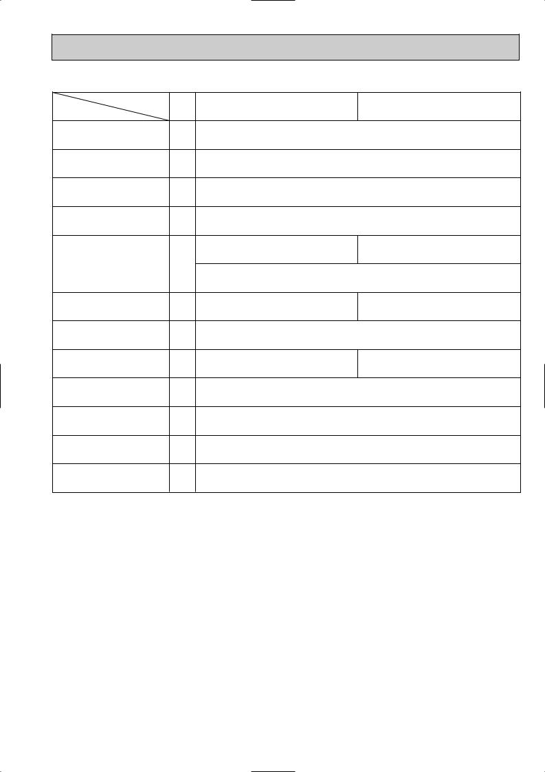
3-3. NOISE CRITERION CURVES
PKFY-P63VFM-E |
|
NOTCH |
SPL(dB) |
LINE |
|||||
|
|
|
|
|
|
|
High |
45 |
|
|
|
|
|
|
|
|
Low |
39 |
|
|
90 |
|
|
|
|
|
|
|
|
bar) |
80 |
|
|
|
|
|
|
|
|
|
|
|
|
|
|
|
|
|
|
dB(0dB=0.0002 |
70 |
|
|
|
|
|
|
|
NC-70 |
|
|
|
|
|
|
|
|
||
60 |
|
|
|
|
|
|
|
|
|
LEVEL, |
|
|
|
|
|
|
|
|
|
|
|
|
|
|
|
|
|
NC-60 |
|
|
|
|
|
|
|
|
|
|
|
PRESSURE |
50 |
|
|
|
|
|
|
|
|
|
|
|
|
|
|
|
|
NC-50 |
|
40 |
|
|
|
|
|
|
|
|
|
SOUND |
|
|
|
|
|
|
|
|
|
|
|
|
|
|
|
|
|
NC-40 |
|
|
|
|
|
|
|
|
|
|
|
BAND |
30 |
|
|
|
|
|
|
|
|
|
|
|
|
|
|
|
|
NC-30 |
|
|
|
|
|
|
|
|
|
|
|
OCTAVE |
20 |
APPROXIMATE |
|
|
|
|
|
|
|
|
TERESHOLD OF |
|
|
|
|
|
|
||
|
HEARING FOR |
|
|
|
|
|
NC-20 |
||
|
|
CONTINUOUS |
|
|
|
|
|
||
|
|
|
|
|
|
|
|
||
|
|
NOISE |
|
|
|
|
|
|
|
|
10 |
63 |
125 |
250 |
500 |
1000 |
2000 |
4000 |
8000 |
|
|
||||||||
BAND CENTER FREQUENCIES, Hz
PKFY-P100VFM-E |
|
NOTCH |
SPL(dB) |
LINE |
|||||
|
|
|
|
|
|
|
High |
46 |
|
|
|
|
|
|
|
|
Low |
41 |
|
|
90 |
|
|
|
|
|
|
|
|
bar) |
80 |
|
|
|
|
|
|
|
|
|
|
|
|
|
|
|
|
|
|
dB(0dB=0.0002 |
70 |
|
|
|
|
|
|
|
NC-70 |
|
|
|
|
|
|
|
|
||
60 |
|
|
|
|
|
|
|
|
|
LEVEL, |
|
|
|
|
|
|
|
|
|
|
|
|
|
|
|
|
|
NC-60 |
|
|
|
|
|
|
|
|
|
|
|
PRESSURE |
50 |
|
|
|
|
|
|
|
|
|
|
|
|
|
|
|
|
NC-50 |
|
40 |
|
|
|
|
|
|
|
|
|
SOUND |
|
|
|
|
|
|
|
|
|
|
|
|
|
|
|
|
|
NC-40 |
|
|
|
|
|
|
|
|
|
|
|
BAND |
30 |
|
|
|
|
|
|
|
|
|
|
|
|
|
|
|
|
NC-30 |
|
|
|
|
|
|
|
|
|
|
|
OCTAVE |
20 |
APPROXIMATE |
|
|
|
|
|
|
|
|
TERESHOLD OF |
|
|
|
|
|
|
||
|
HEARING FOR |
|
|
|
|
|
NC-20 |
||
|
|
CONTINUOUS |
|
|
|
|
|
||
|
|
|
|
|
|
|
|
||
|
|
NOISE |
|
|
|
|
|
|
|
|
10 |
63 |
125 |
250 |
500 |
1000 |
2000 |
4000 |
8000 |
|
|
||||||||
BAND CENTER FREQUENCIES, Hz
UNIT
WALL
1m
1m
MICROPHONE
10
 Loading...