


PKFY-P20VBM-E

Air-Conditioners For Building Application
INDOOR UNIT
PKFY-P·VBM-E / PKFY-P·VHM-E
PCFY-P·VKM-E / PFFY-P·VKM-E
PMFY-P·VBM-E
OPERATION MANUAL
For safe and correct use, please read this operation manual thoroughly before operating the air-conditioner unit.
BEDIENUNGSHANDBUCH
Zum sicheren und einwandfreien Gebrauch der Klimaanlage dieses Bedienungshandbuch vor Inbetriebnahme
gründlich durchlesen.
MANUEL D’UTILISATION
Pour une utilisation correcte sans risques, veuillez lire le manuel d’utilisation en entier avant de vous servir du
climatiseur.
BEDIENINGSHANDLEIDING
Voor een veilig en juist gebruik moet u deze bedieningshandleiding grondig doorlezen voordat u de
airconditioner gebruikt.
MANUAL DE INSTRUCCIONES
Lea este manual de instrucciones hasta el fi nal antes de poner en marcha la unidad de aire acondicionado
para garantizar un uso seguro y correcto.
ISTRUZIONI DI FUNZIONAMENTO
Leggere attentamente questi istruzioni di funzionamento prima di avviare l’unità, per un uso corretto e sicuro
della stessa.
ΕΓΧΕΙΡΙΔΙΟ ΟΔΗΓΙΩΝ ΧΡΗΣΕΩΣ
Για ασφάλεια και σωστή χρήση, παρακαλείστε διαβάσετε προσεχτικά αυτό το εγχειρίδιο χρήσεως πριν θέσετε
σε λειτουργία τη μονάδα κλιματισμού.
MANUAL DE OPERAÇÃO
Para segurança e utilização correctas, leia atentamente o manual de operação antes de pôr a funcionar a unidade de ar condicionado.
FOR USER
FÜR BENUTZER
POUR L’UTILISATEUR
VOOR DE GEBRUIKER
PARA EL USUARIO
PER L’UTENTE
ΓΙΑ ΤΟΝ ΧΡΗΣΤΗ
PARA O UTILIZADOR
English
Deutsch
Français
Nederlands
Español
Italiano
Ελληνικά
Português
Işletme Elkitabı
Emniyetli ve doğru biçimde nasıl kullanılacağını öğrenmek için lütfen klima cihazını işletmeden önce bu
elkitabını dikkatle okuyunuz.
РУКОВОДСТВО ПО ЭКСПЛУАТАЦИИ
Для обеспечения правильного и безопасного использования следует ознакомиться с инструкциями, указанными в
данном руководстве по эксплуатации, тщательным образом до того, как приступать к использованию кондиционера.
操作说明书
在操作空调机之前,请全面阅读本操作说明书,以便安全和正确地使用本机。
KULLANICI İÇİN
ДЛЯ ПОЛЬЗОВАТЕЛЯ
用户适用(安装人员适用)
Türkçe
Русский
中文
Contents
1. Safety Precautions .............................................................................2
2. Parts Names ....................................................................................... 3
3. Screen Confi guration .......................................................................... 6
4. Setting the Day of the Week and Time ............................................... 6
5. Operation ............................................................................................ 6
6. Timer...................................................................................................8
1. Safety Precautions
Before installing the unit, make sure you read all the “Safety
Precautions”.
The “Safety Precautions” provide very important points re-
garding safety. Make sure you follow them.
Please report to or take consent by the supply authority be-
fore connection to the system.
Warning:
• The unit must not be installed by the user. Ask the dealer or an
authorized company to install the unit. If the unit is installed improperly, water leakage, electric shock or fi re may result.
• Do not stand on, or place any items on the unit.
• Do not splash water over the unit and do not touch the unit with
wet hands. An electric shock may result.
• Do not spray combustible gas close to the unit. Fire may result.
• Do not place a gas heater or any other open-flame appliance
where it will be exposed to the air discharged from the unit. Incomplete combustion may result.
• Do not remove the front panel or the fan guard from the outdoor
unit when it is running.
• Never repair the unit or transfer it to another site by yourself.
7. Other Functions ...............................................................................11
8. Function Selection .......................................................................... 12
9. Emergency operation for wireless remote-controller ...................... 16
10. Care and Cleaning.......................................................................... 16
11. Trouble Shooting ............................................................................. 18
12. Specifi cations .................................................................................20
Symbols used in the text
Warning:
Describes precautions that should be observed to prevent danger
of injury or death to the user.
Caution:
Describes precautions that should be observed to prevent damage
to the unit.
Symbols used in the illustrations
: Indicates a part which must be grounded.
• When you notice exceptionally abnormal noise or vibration, stop
operation, turn off the power switch, and contact your dealer.
• Never insert fi ngers, sticks etc. into the intakes or outlets.
• If you detect odd smells, stop using the unit, turn off the power
switch and consult your dealer. Otherwise, a breakdown, electric
shock or fi re may result.
• This air conditioner is NOT intended for use by children or infi rm
persons without supervision.
• Young children must be supervised to ensure that they do not
play with the air conditioner.
• If the refrigeration gas blows out or leaks, stop the operation of
the air conditioner, thoroughly ventilate the room, and contact
your dealer.
Caution:
• Do not use any sharp object to push the buttons, as this may
damage the remote controller.
• Never block or cover the indoor or outdoor unit’s intakes or outlets.
• Never wipe the remote controller with benzene, thinner chemical
rags, etc.
• Do not operate the unit for a long time in high humidity, e.g. leaving a door or window open. In the cooling mode, if the unit is operated in a room with high humidity (80% RH or more) for a long
time, water condensed in the air conditioner may drop and wet or
damage furniture, etc.
• Do not touch the upper air outlet vane or the lower air outlet
damper during operation. Otherwise, condensation may form and
the unit may stop operating.
Disposing of the unit
When you need to dispose of the unit, consult your dealer.
2

2. Parts Names
Indoor Unit
PKFY -P·VBM-E PKFY -P·VHM-E PCFY-P·VKM-E PMFY-P·VBM-E PFFY-P·VKM-E
Fan speed 4 speed 3 speed+ Auto* 4 speed+ Auto* 4 speed 4 speed
Vane
Louver Manual Manual Manual Manual Manual
Filter Normal Normal Long-life Normal Normal
Filter cleaning indication
PMFY-P·VBM-E
1-way Ceiling Cassette
Steps 4 steps 5 steps 5 steps 4 steps 4 steps
Auto swing
100 hr 100 hr 2,500 hr 100 hr 100 hr
* This operation is available only using the remote controller
that is able to set its Fan speed setting "Auto".
Filter
PKFY-P·VBM-E
Wall Mounted
Air outlet
Filter Air intake
Louver
Vane
Air inlet
Air outlet
Vane
Louver
PKFY-P·VHM-E
Wall Mounted
Filter
Louver
Air outlet
Air intake
Vane
PCFY-P·VKM-E
Ceiling Suspended
Air outlet
Vane
Louver
Air intake
PFFY-P·VKM-E
Floor Standing
Filter
(Inside of Air intake)
Louver
Air outlet Air inlet
Vane
Filter
Damper
Air outlet
Louver
3
2. Parts Names
Wired Remote-Controller
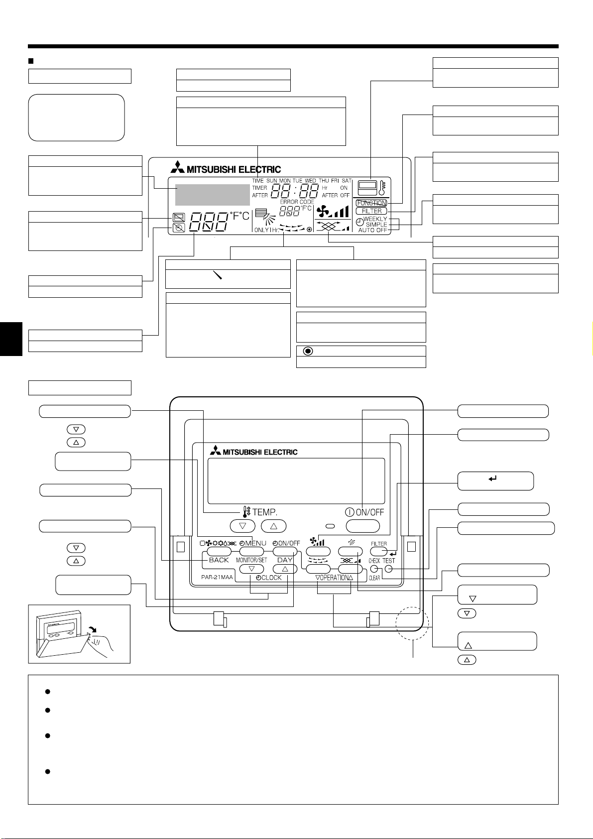
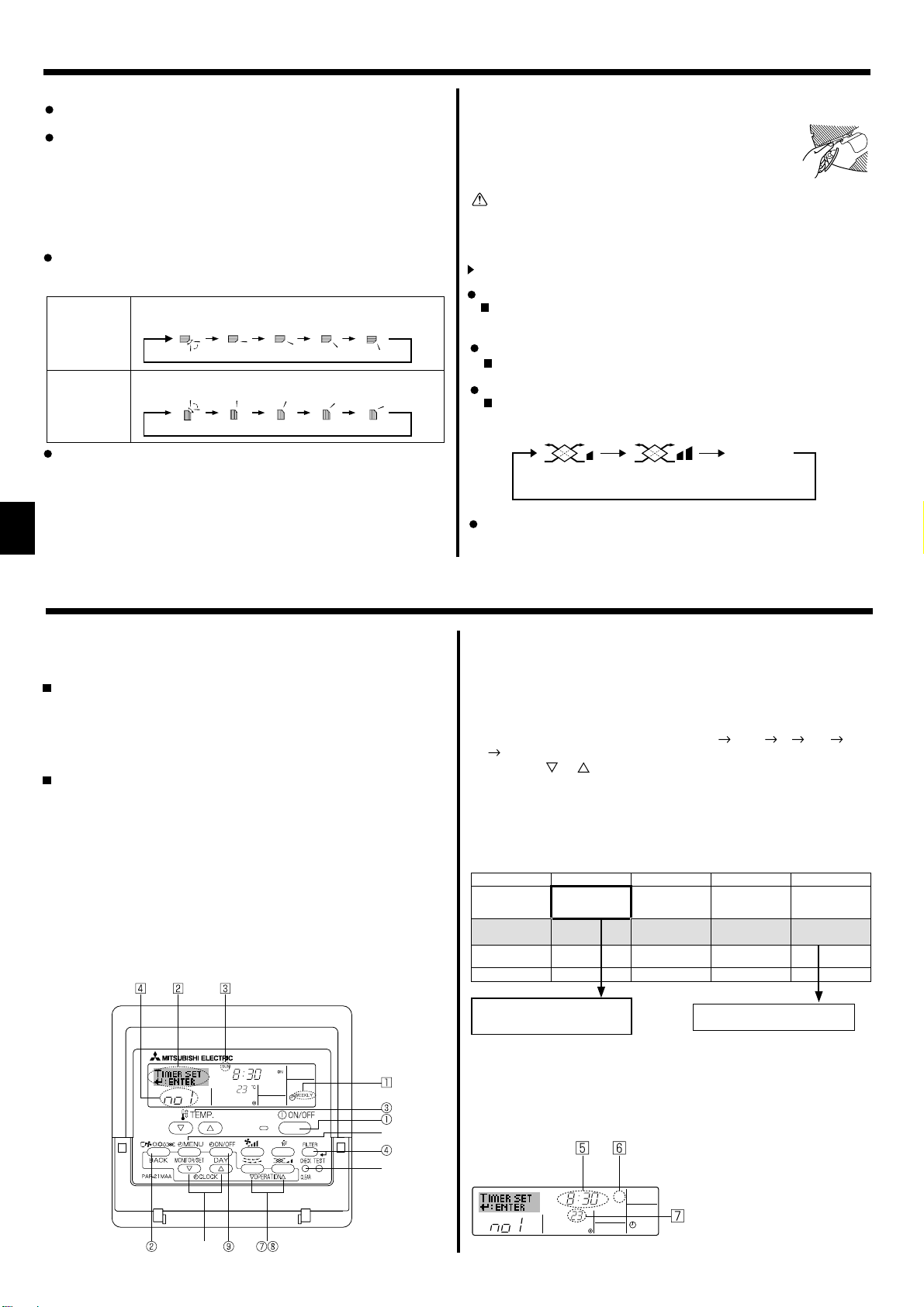
Display Section
For purposes of this explanation, all parts of the display are
shown. During actual operation,
only the relevant items will be
displayed.
Identifi es the current operation
Shows the operating mode, etc.
* Multi-language display is sup-
ported.
“Centrally Controlled” indicator
Indicates that operation of the
remote controller has been prohibited by a master controller.
“Timer is Off” indicator
Indicates that the timer is off.
Temperature Setting
Shows the target temperature.
Day-of-Week
Shows the current day of the week.
Time/Timer Display
Shows the current time, unless the simple or Auto
Off timer is set.
If the simple or Auto Off timer is set, shows the
time remaining.
Up/Down Air Direction indicator
The indicator
of the airfl ow.
“One Hour Only” indicator
Displayed if the airfl ow is set to Low and
downward during COOL or DRY mode.
(Operation varies according to model.)
The indicator goes off after one hour
when the airfl ow direction also changes.
shows the direction
Room Temperature display
Shows the room temperature. The room
temperature display range is 8–39°C.
The display blinks if the temperature is
less than 8°C or 39°C or more.
Louver display
Indicates the action of the swing louver.
Does not appear if the louver is stationary.
Indicates that the power is on.
(Power On indicator)
“Sensor” indication
Displayed when the remote controller
sensor is used.
“Locked” indicator
Indicates that remote controller but-
tons have been locked.
“Clean The Filter” indicator
Comes on when it is time to clean
the fi lter.
Timer indicators
The indicator comes on if the corre-
sponding timer is set.
Fan Speed indicator
Shows the selected fan speed.
Ventilation indicator
Appears when the unit is running in
Ventilation mode.
Operation Section
Set T emperature buttons
Down
Up
Timer Menu button
(Monitor/Set button)
Mode button (Return button)
Set Time buttons
Back
Ahead
Timer On/Off button
(Set Day button)
Opening
the door
Built-in temperature sensor
ON/OFF button
Fan Speed button
Filter button
(<Enter> button)
Test Run button
Check button (Clear button)
Airfl ow Up/Down button
Louver button
Operation button)
(
To return operation
number
Ventilation button
Operation button)
(
To go to next operation number
Note:
“PLEASE WAIT” message
This message is displayed for approximately 3 minutes when power is supplied to the indoor unit or when the unit is recovering from a power failure.
Operation mode blinking display
When multiple indoor units are connected to a single outdoor unit and an operation mode is selected for one indoor unit that is different from the current
operation mode of another indoor unit, the operation mode display blinks. Select the same operation mode of the other indoor unit.
“NOT AVAILABLE” message
This message is displayed if a button is pressed to operate a function that the indoor unit does not have.
When the same remote controller is used to operate multiple indoor units, this message is displayed if the main indoor unit is not equipped with the
selected function.
Room temperature display
The indoor unit temperature sensors or the remote controller temperature sensor can be selected to measure the room temperature. The indoor unit
temperature sensors are the initial setting. When the indoor unit temperature sensors are selected to measure the room temperature, the room temperature measured at the main indoor unit is displayed on the remote controller that operates multiple indoor units.
4

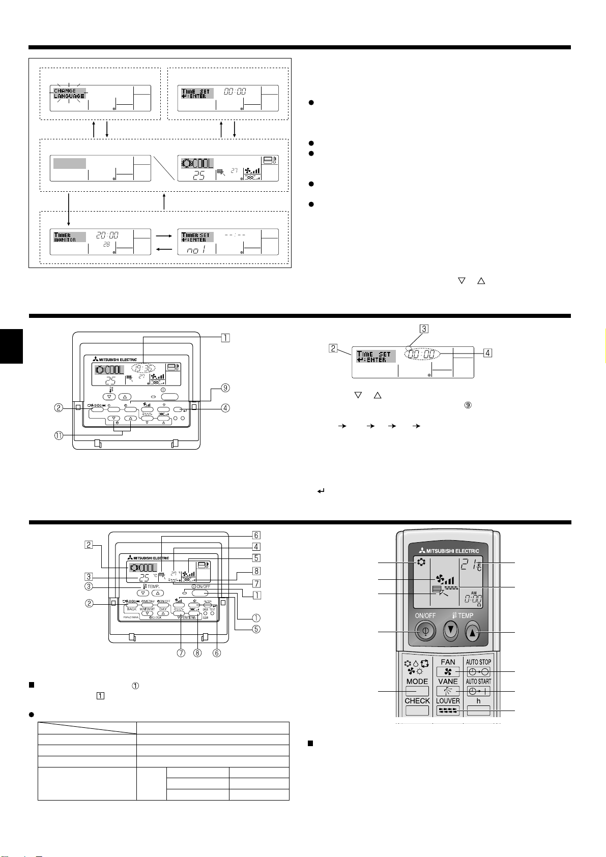
2. Parts Names
Wireless Remote-Controller
Transmission area
Remote controller display
* For explanation purposes, all of the items
that appear in the display are shown.
* All items are displayed when the Reset
button is pressed.
ON/OFF button
Set Temperature buttons
Fan Speed button (Changes fan speed)
Airfl ow button (Changes up/down airfl ow direction)
Mode button (Changes operation mode)
Check button
Test Run button
Transmission indicator
Timer indicator
Operation areas
Timer Off button
Timer On button
Hour button
Minute button
Set Time button (Sets the time)
Louver button (Changes left/right airfl ow direction)
Reset button
When using the wireless remote controller, point it towards the receiver on the indoor unit.
If the remote controller is operated within approximately two minutes after power is supplied
to the indoor unit, the indoor unit may beep twice as the unit is performing the initial automatic
check.
The indoor unit beeps to confirm that the signal transmitted from the remote controller has
been received. Signals can be received up to approximately 7 meters in a direct line from the
indoor unit in an area 45° to the left and right of the unit. However, illumination such as fl uores-
cent lights and strong light can affect the ability of the indoor unit to receive signals.
If the operation lamp near the receiver on the indoor unit is blinking, the unit needs to be in-
spected. Consult your dealer for service.
Handle the remote controller carefully! Do not drop the remote controller or subject it to strong
shocks. In addition, do not get the remote controller wet or leave it in a location with high humidity.
To avoid misplacing the remote controller, install the holder included with the remote controller
on a wall and be sure to always place the remote controller in the holder after use.
Battery installation/replacement
1. Remove the top cover, insert two AAA batteries, and then install the top cover.
1
2
Top cover
2. Press the Reset button.
3
Two AAA batteries
Insert the negative (–)
end of each battery fi rst.
Install the batteries in
the correct directions
(+, –)!
Press the Reset button
with an object that has
a narrow end.
5
3. Screen Confi guration
Function Selection of remote controller
A
Standard Control Screens
OFF ON
BC
Timer Monitor Timer Setup
MON
TIMER
OFF
°F°C
WEEKLY
B
Set Day/Time
TIME SUN
DC
°F°C
°C
SUN MON TUE WEDTHU FRI SAT
WEEKLY
4. Setting the Day of the Week and Time
Day of the Week &
TIME SUN
°C
°C
TEMP.
MENU
MONITOR/SET
BACK DAY
PAR-21MAA
ON/OFF
CLOCK
OPERATION
ON/OFF
FILTER
CHECK
CLEAR
TEST
Note:
The day and time will not appear if clock use has been disabled at
Function Selection of remote controller.
Time display
<Screen Types>
For details on setting the language for the remote controller display, refer
to section 8. Function Selection.
The initial language setting is English.
Function Selection of remote controller:
Set the functions and ranges available to the
remote controller (timer functions, operating
restrictions, etc.)
Set Day/Time: Set the current day of the week or time.
Standard Control Screens:
View and set the air conditioning system’s op-
erating status.
Timer Monitor: View the currently set timer (weekly timer, sim-
ple timer or Auto Off timer).
Timer Setup: Set the operation of any of the timers (weekly
timer, simple timer or Auto Off timer).
<How to change the screen>
: Hold down both the Mode button and the Timer On/Off button for 2
A
seconds.
: Press the Timer Menu button.
B
: Press the Mode (Return) button.
C
: Press either of the Set Time buttons ( or ).
D
Day of the Week Setting
TIME SUN
1. Press the or
Set Time button 1 to show display 2.
2. Press the Timer On/Off (Set Day) button
* Each press advances the day shown at
Sun
Mon ... Fri Sat.
3
Time Setting
to set the day.
:
3. Press the appropriate Set Time button 1 as necessary to set the time.
* As you hold the button down, the time (at
) will increment fi rst in
4
one-minute intervals, then in ten-minute intervals, and then in onehour intervals.
4. After making the appropriate settings at Steps 2 and 3, press the Filter
button
to lock in the values.
4
5. Operation
5.1. Turning ON/OFF
<To Start Operation>
Press the ON/OFF button .
• The ON lamp and the display area come on.
Note:
When the unit is restarted, initial settings are as follows.
Remote Controller settings
Mode Last operation mode
Temperature setting Last set temperature
Fan speed Last set fan speed
Airfl ow up/down
Mode
COOL or DRY
HEAT
FAN
*1
Last setting might be applied depending on the type of the indoor unit.
*2 In case of the last setting is swing, airfl ow might be Downward 4 de-
pending on the type of the indoor unit.
Horiz. outlet
Last setting
Horiz. outlet
6
*1
*2
*1
2
3
5
6
1
7
3
5
2
6
7
<To Stop Operation>
Press the ON/OFF button
• The ON lamp
and the display area go dark.
1
Note:
Even if you press the ON/OFF button immediately after shutting
down the operation is progress, the air conditioner will not start
for about three minutes. This is to prevent the internal components
from being damaged.
1
again.
Swing
Auto 1 2
3
4
5
5. Operation
5.2. Mode select
Press the operation mode ( ) button 2 and select the operation mode
Automatic operation
According to a set temperature, cooling operation starts if the room
temperature is too hot and heating operation starts if the room temperature is too cold.
During automatic operation, if the room temperature changes and
remains 1.5 °C or more above the set temperature for 3 minutes, the
air conditioner switches to cooling mode. In the same way, if the room
temperature remains 1.5°C or more below the set temperature for 3
minutes, the air conditioner switches to heating mode.
Cooling mode
Because the room temperature is automatically adjusted in order to
maintain a fi xed effective temperature, cooling operation is performed
a few degrees warmer and heating operation is performed a few degrees cooler than the set room temperature once the temperature is
reached (automatic energy-saving operation).
.
2
Cooling mode
Drying mode
Fan mode
Heating mode
Automatic (cooling/heating) mode
3 minutes (switches from
heating to cooling)
3 minutes (switches from cooling to heating )
Set temperature +1.5°C
Set temperature
Set temperature -1.5°C
Note:
The number of available fan speeds depends on the type of unit
connected. Note also that some units do not provide an “Auto”
setting.
In the following cases, the actual fan speed generated by the unit
will differ from the speed shown the remote controller display.
1. While the display is showing “STAND BY” or “DEFROST”.
2. When the temperature of the heat exchanger is low in the heating mode. (e.g. immediately after heating operation starts)
3. In HEAT mode, when room temperature is higher than the temperature setting.
4. When the unit is in DRY mode.
■
Automatic fan speed setting (For wireless remote controller)
It is necessary to set for wireless remote controller only when
automatic fan speed is not set at default setting.
It is not necessary to set for wired remote controller with automatic
fan speed at default setting.
Press the SET button with something sharp at the end.
1
Operate when display of remote controller is off.
MODEL SELECT
blinks and Model No. is lighted
Press the AUTO STOP button.
2
blinks and setting No. is lighted
A.
B.
(Setting No.01: without automatic fan speed )
Press the temp.
3
(Setting No.02:with automatic fan speed )
If you mistook the operation, press the ON/OFF
buttons to set the setting No.02.
button and oper-
ate again from procedure 2.
Press the SET button with something sharp at the end.
4
MODEL SELECT
and Model No. are lighted for 3 seconds, then turned off.
MODEL SELECT
ON/OFF TEMP
B
A
5.3. Temperature setting
To decrease the room temperature:
Press button
The selected temperature is displayed at
to set the desired temperature.
3
.
3
To increase the room temperature:
Press button
The selected temperature is displayed at
to set the desired temperature.
3
.
3
• Available temperature ranges are as follows:
Cooling/Drying: 19 - 30 °C
Heating: 17 - 28 °C
Automatic: 19 - 28 °C
• The display blinks either 8°C - 39°C to inform you if the room temperature is lower or higher than the displayed temperature.
5.4. Fan speed setting
Press the Fan Speed button 5 as many times as necessary while the
system is running.
• Each press changes the force. The currently selected speed is
shown at
• The change sequence, and the available settings are as follows.
FAN SPEED
4-speed
+
Auto *
3-speed
+
Auto *
4-speed
model
* For MA remote controller only.
Automatic fan speed setting is necessary for wireless remote controller.
.
5
Display
Speed 1 Speed 2 Speed 3 Speed 4 Auto
Speed 1 Speed 2 Speed 3 Auto
Speed 1 Speed 2 Speed 3 Speed 4
3
2
h
min
14
MODE
CHECK
TEST RUN
FAN
VANE
LOUVER
RESETSET CLOCK
AUTO STOP
AUTO START
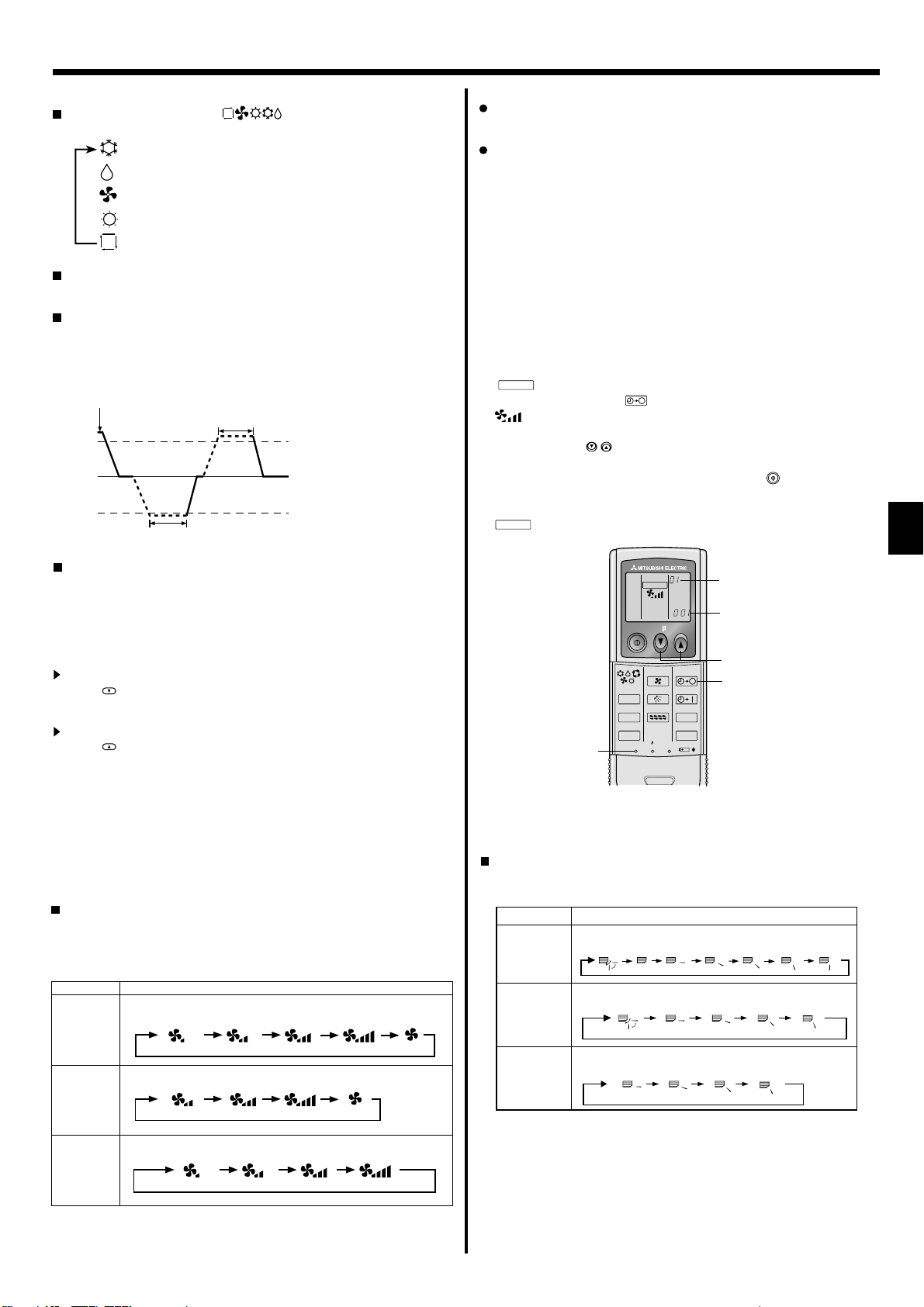
5.5. Airfl ow direction setting
<To Change the Airfl ow’s Up/Down Direction>
With the unit running, press the Airfl ow Up/Down button 6 as necessary.
•
Each press changes the direction. The current direction is shown at 6.
• The change sequence, and the available settings, are as follows.
Airfl ow Display
5 steps
model*1
4 steps
model
(PMFY)
4 steps
model
(PKFY-BM)
Swing
(Horiz.)
* Note that during swing operation, the directional indication on the
screen does not change in sync with the directional vanes on the unit.
* Some models do not support directional settings.
*1. For MA remote controller only, other remote controllers display the
same as 4steps model.
*2. Airfl ow direction setting <Auto>
COOL/FAN/DRY : Setting 1 (Horizontal), HEAT : Setting 5 (Downward 5)
123 4
(Horiz.)
123 4
7
5. Operation
Note:
Available directions depend on the type of unit connected. Note
also that some units do not provide an “Auto” setting.
In the following cases, the actual air direction will differ from the
direction indicated on the remote controller display.
1. While the display is showing “STAND BY” or “DEFROST”.
2. Immediately after starting heater mode (while the system is
waiting for the mode change to take effect).
3. In heat mode, when room temperature is higher than the temperature setting.
(For PFFY-P·VKM series)
For the PFFY-P·VKM series, the airfl ow direction displayed on the
remote controller is different from the actual airflow direction.
Refer to the following table.
Display
Actual
Swing
Swing
123 4
(Horiz.)
1234
(Horiz.)
The airfl ow direction for the lower air outlet damper cannot be set.
The airfl ow direction is automatically controlled by a computer.
<[Manual] To Change the Airfl ow’s Left/Right Direction>
* The louver button 7 cannot be used.
• Stop the unit operation, hold the lever of the louver,
and
adjust to the desired direction.
* Do not set to the inside direction when the unit is
in the cooling or drying mode because there is a
risk of condensation and water dripping.
Caution:
When you operate the process above, be sure to take measures to avoid falls.
5.6. Ventillation
For LOSSNAY combination
5.6.1. For Wired Remote-controller
To run the ventilator together with the indoor unit:
Press the ON/OFF button 1.
•
The Vent indication appears on the screen (at 8). The ventilator
will now automatically operate whenever the indoor unit is running.
To run the ventilator only when the indoor unit is off:
Press the Ventilation button 8 while the indoor unit is off.
• The On lamp (at 1 ) and the Vent indication (at 8) come on.
To change the ventilator force:
Press the Ventilation button 8 as necessary.
• Each press toggles the setting as shown below.
No display
(Stop)
(Low)
(High)
Note:
With some model confi gurations, the fan on the indoor unit may
come on even when you set the ventilator to run independently.
(OFF)
6. Timer
6.1. For Wired Remote-controller
You can use Function Selection of remote controller to select which of three
types of timer to use: 1 Weekly timer, 2 Simple timer or 3 Auto Off timer.
6.1.1. Weekly Timer
The weekly timer can be used to set up to eight operations for each
day of the week.
• Each operation may consist of any of the following: ON/OFF time
together with a temperature setting, or ON/OFF time only, or temperature setting only.
• When the current time reaches a time set at this timer, the air conditioner carries out the action set by the timer.
Time setting resolution for this timer is 1 minute.
Note:
*1. Weekly Timer/Simple Timer/Auto Off Timer cannot be used at
the same time.
*2. The weekly timer will not operate when any of the following con-
ditions is in effect.
The timer feature is off; the system is in an malfunction state; a
test run is in progress; the remote controller is undergoing selfcheck or remote controller check; the user is in the process of
setting a function; the user is in the process of setting the timer;
the user is in the process of setting the current day of the week
or time; the system is under central control. (Specifically, the
system will not carry out operations (unit on, unit off, or temperature setting) that are prohibited during these conditions.)
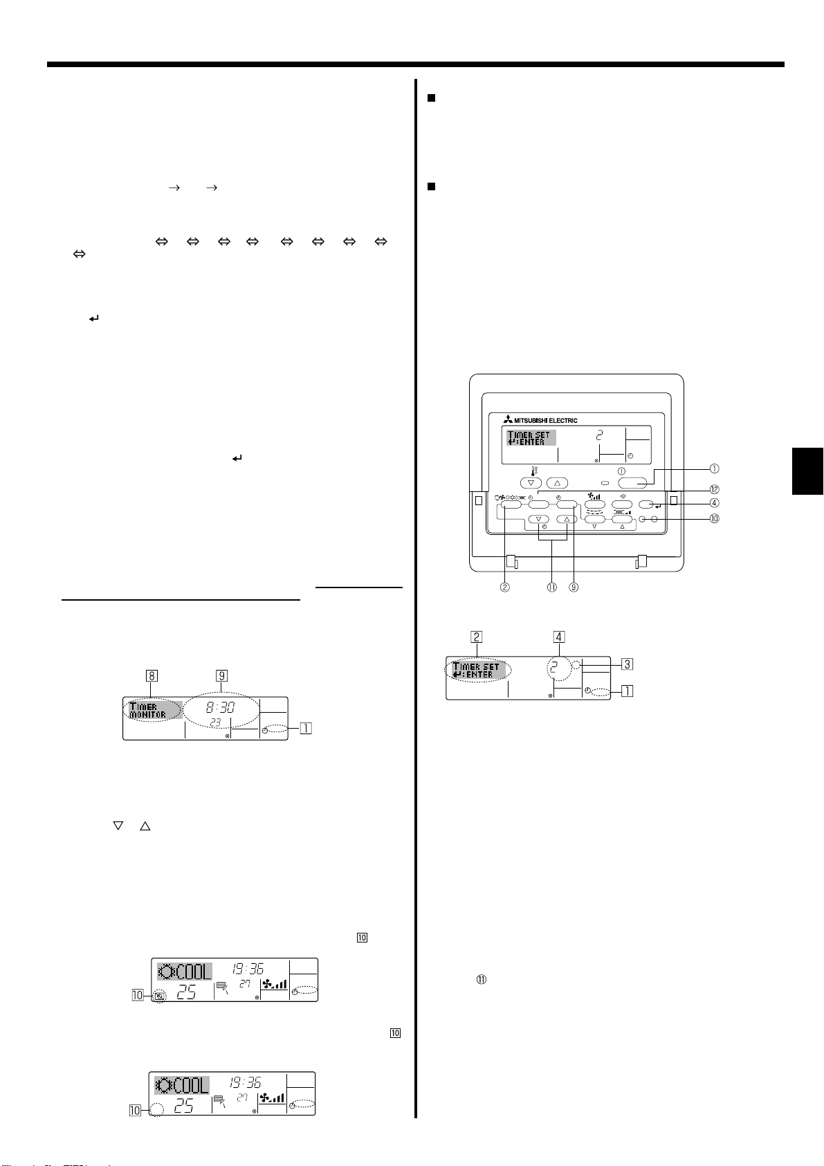
Operation No.
Day Setting
<How to Set the Weekly Timer>
1. Be sure that you are at a standard control screen, and that the weekly
timer indicator 1 is shown in the display.
2. Press the Timer Menu button 2, so that the “Set Up” appears on the
screen (at 2). (Note that each press of the button toggles the display
between “Set Up” and “Monitor”.)
3. Press the Timer On/Off (Set Day) button 9 to set the day. Each press
advances the display at 3 to the next setting, in the following sequence: “Sun Mon Tues Wed Thurs Fri Sat”
“Sun” ... “Fri” “Sat”
“Sun Mon Tues Wed Thurs Fri Sat”...
4. Press the or Operation button (7 or 8) as necessary to select
the appropriate operation number (1 to 8) 4.
* Your inputs at Steps 3 and 4 will select one of the cells from the
matrix illustrated below.
(The remote-controller display at left shows how the display would
appear when setting Operation 1 for Sunday to the values indicated
below.)
Setup Matrix
Op No. Sunday Monday … Saturday
No. 1
No. 2
…
No. 8
<Operation 1 settings for Sunday>
Start the air conditioner at 8:30, with
the temperature set to 23 °C
• 8:30
• ON
• 23°C
• 10:00
• OFF
• 10:00
• OFF
• 10:00
• OFF
<Operation 2 settings for every day>
Turn off the air conditioner at 10:00.
• 10:00
• OFF
Note:
By setting the day to “Sun Mon Tues Wed Thurs Fri Sat”, you can
set the same operation to be carried out at the same time every day.
(Example: Operation 2 above, which is the same for all days of the
week.)
Shows the time setting
Shows the selected operation (ON or OFF)
* Does not appear if operation is not set.
SUN
ON
°C
WEEKLY
Shows the temperature setting
* Does not appear if temperature is
not set.
8
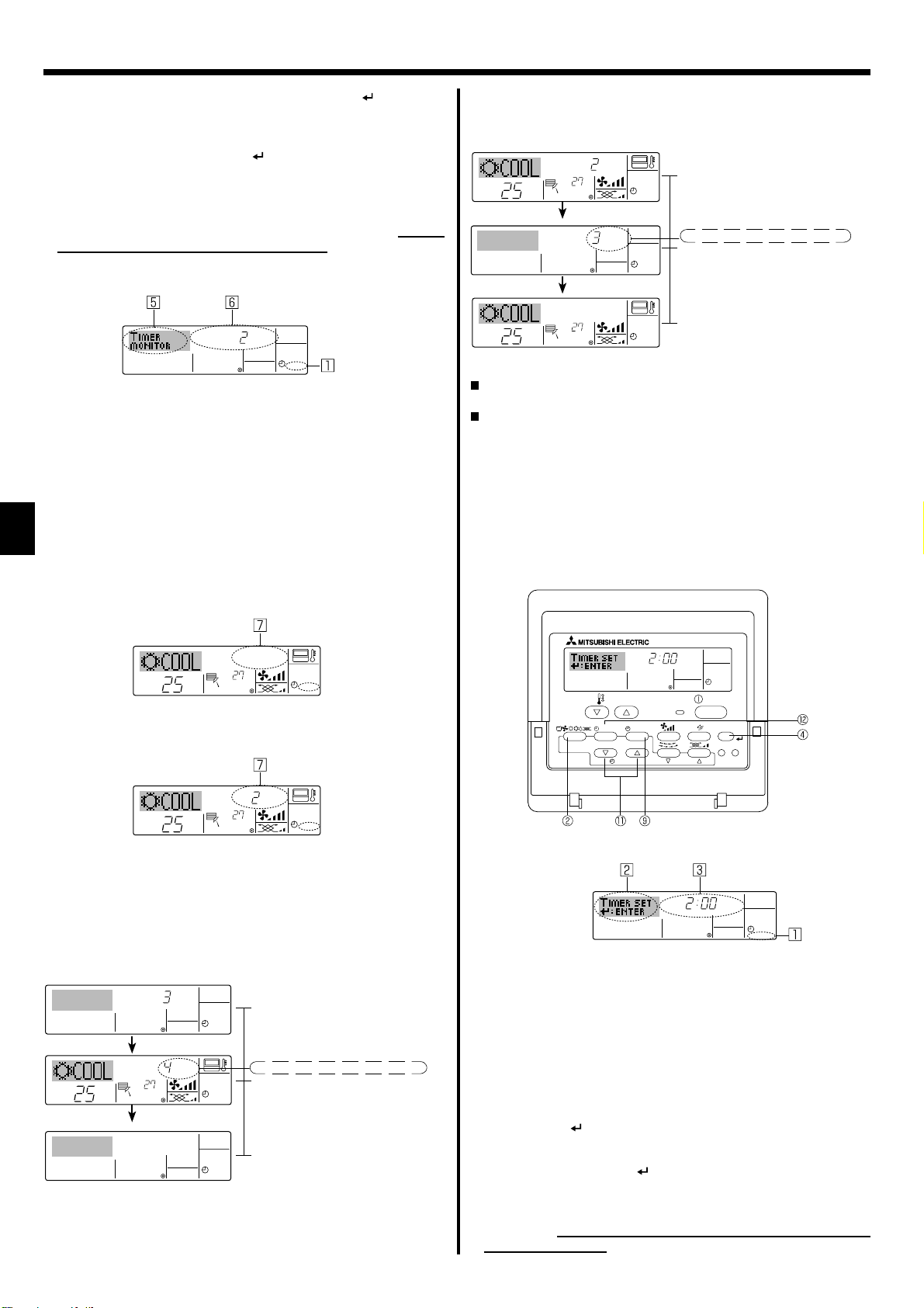
6. Timer
<Setting the Weekly Timer>
5. Press the appropriate Set Time button 1 as necessary to set the desired time (at 5).
* As you hold the button down, the time fi rst increments in minute in-
tervals, then in ten-minute intervals, and then in one-hour intervals.
6. Press the ON/OFF button 1 to select the desired operation (ON or
OFF) at 6.
* Each press changes the next setting, in the following sequence: No
display (no setting)
“ON” “OFF”
7. Press the appropriate Set Temperature button 3 to set the desired
temperature (at 7 ).
* Each press changes the setting, in the following sequence: No dis-
play (no setting) 24 25 ... 29 30 12 ... 23
No display.
(Available range: The range for the setting is 12°C to 30°C. The ac-
tual range over which the temperature can be controlled, however,
will vary according to the type of the connected unit.)
8. After making the appropriate settings at Steps 5, 6 and 7, press the
Filter button 4 to lock in the values.
To clear the currently set values for the selected operation, press and
quickly release the Check (Clear) button 0 once.
* The displayed time setting will change to “—:—”, and the On/Off
and temperature settings will all disappear.
(To clear all weekly timer settings at once, hold down the Check
(Clear) button 0 for two seconds or more. The display will begin
blinking, indicating that all settings have been cleared.)
Note:
Your new entries will be cancelled if you press the Mode (Return)
button 2 before pressing the Filter button 4.
If you have set two or more different operations for exactly the
same time, only the operation with the highest Operation No. will be
carried out.
9. Repeat Steps 3 to 8 as necessary to fi ll as many of the available cells
as you wish.
10.Press the mode (Return) button 2 to return to the standard control
screen and complete the setting procedure.
11.To activate the timer, press the Timer On/Off button 9, so that the
“Timer Off” indication disappears from the screen. Be sure that the
“Timer Off” indication is no longer displayed.
* If there are no timer settings, the “Timer Off” indication will blink on
the screen.
<How to View the Weekly Timer Settings>
Timer Settings
SUN
TIMER
ON
OFF
°C
WEEKLY
1. Be sure that the weekly timer indicator is visible on the screen (at 1).
2. Press the Timer Menu button 2 so that “Monitor” is indicated on the
screen (at 8).
3. Press the Timer On/Off (Set Day) button 9 as necessary to select the
day you wish to view.
4. Press the or Operation button (7 or 8) as necessary to change
the timer operation shown on the display (at 9 ).
* Each press will advance to the next timer operation, in order of time
setting.
5. To close the monitor and return to the standard control screen, press
the Mode (Return) button 2.
<To Turn Off the Weekly Timer>
Press the Timer On/Off button 9 so that “Timer Off” appears at .
TIME SUN
°C
°C
WEEKLY
<To Turn On the Weekly Timer>
Press the Timer On/Off button 9 so that the “Timer Off” indication (at )
goes dark.
TIME SUN
°C
°C
WEEKLY
6.1.2. Simple Timer
You can set the simple timer in any of three ways.
• Start time only:
The air conditioner starts when the set time has elapsed.
• Stop time only:
The air conditioner stops when the set time has elapsed.
• Start & stop times:
The air conditioner starts and stops at the respective elapsed times.
The simple timer (start and stop) can be set only once within a
72-hour period.
The time setting is made in hour increments.
Note:
*1. Weekly Timer/Simple Timer/Auto Off Timer cannot be used at
the same time.
*2. The simple timer will not operate when any of the following con-
ditions is in effect.
The timer is off; the system is in malfunction state; a test run is
in progress; the remote controller is undergoing self-check or
remote controller check; the user is in the process of selecting
a function; the user is in the process of setting the timer; the
system is under central control. (Under these conditions, On/Off
operation is prohibited.)
ONHr
AFTER
SIMPLE
TEMP.
MENU
ON/OFF
BACK DAY
MONITOR/SET
PAR-21MAA
CLOCK
<How to Set the Simple Timer>
Timer Setting
ONHr
AFTER
1. Be sure that you are at a standard control screen, and that the simple
timer indicator is visible in the display (at 1).
When something other than the Simple Timer is displayed, set it to
SIMPLE TIMER using the function selection of remote controller (see
8.[4]–3 (3)) timer function setting.
2. Press the Timer Menu button 2, so that the “Set Up” appears on the
screen (at 2). (Note that each press of the button toggles the display
between “Set Up” and “Monitor”.)
3. Press the ON/OFF button 1 to display the current ON or OFF simple
timer setting. Press the button once to display the time remaining to
ON, and then again to display the time remaining to OFF. (The ON/
OFF indication appears at 3).
• “ON” timer:
The air conditioner will start operation when the specifi ed number of
hours has elapsed.
• “OFF” timer:
The air conditioner will stop operation when the specifi ed number of
hours has elapsed.
4. With “ON” or “OFF” showing at 3: Press the appropriate Set Time
button as necessary to set the hours to ON (if “ON” is displayed) or
the hours to OFF (if “OFF” is displayed) at 4.
• Available Range: 1 to 72 hours
5. To set both the ON and OFF times, repeat Steps 3 and 4.
* Note that ON and OFF times cannot be set to the same value.
6. To clear the current ON or OFF setting: Display the ON or OFF setting
(see step 3) and then press the Check (Clear) button 0 so that the
time setting clears to “—” at 4. (If you want to use only an ON setting
or only an OFF setting, be sure that the setting you do not wish to use
is shown as “—”.)
OPERATION
SIMPLE
ON/OFF
FILTER
CHECK
TEST
CLEAR
Action (On or Off)
* “— —” is displayed if there is no
setting.
9
AFTER OFF
AUTOOFF
6. Timer
7. After completing steps 3 to 6 above, press the Filter button 4 to
lock in the value.
Note:
Your new settings will be cancelled if you press the Mode (Return)
button 2 before pressing the Filter
button 4.
8. Press the Mode (Return) button 2 to return to the standard control
screen.
9. Press the Timer On/Off button 9 to start the timer countdown. When
the timer is running, the timer value is visible on the display. Be sure
that the timer value is visible and appropriate.
<Viewing the Current Simple Timer Settings>
Timer Setting
TIMER ON
OFFHrAFTER
SIMPLE
1. Be sure that the simple timer indicator is visible on the screen (at 1).
2. Press the Timer Menu button 2, so that the “Monitor” appears on the
screen (at 5).
• If the ON or OFF simple timer is running, the current timer value will
appear at 6.
• If ON and OFF values have both been set, the two values appear
alternately.
3. Press the Mode (Return) button 2 to close the monitor display and
return to the standard control screen.
<To Turn Off the Simple Timer...>
Press the Timer On/Off button 9 so that the timer setting no longer appears on the screen (at 7).
Example 2:
Start the timer with OFF time set earlier than ON time
ON Setting : 5 hours
OFF Setting: 2 hours
OFFHrAFTER
°C
°C
°C
ONHr
AFTER
°C
At Timer Start
Display shows the timer’s OFF setting (hours
SIMPLE
remaining to OFF).
At 3 hours after timer start
Display changes to show the timer’s ON setting
(hours remaining to ON).
SIMPLE
The time displayed is ON setting (5 hours) – OFF
setting (2 hours) = 3 hours.
At 5 hours after timer start
The air conditioner comes on and will continue to
SIMPLE
run until it is turned off.
6.1.3. Auto Off Timer
This timer begins countdown when the air conditioner starts and shuts
the air conditioner off when the set time has elapsed.
Available settings run from 30 minutes to 4 hours in 30-minute intervals.
Note:
*1. Weekly Timer/Simple Timer/Auto Off Timer cannot be used at
the same time.
*2.
The Auto Off timer will not operate when any of the following conditions is in effect
The timer is off; the system is in malfunction state; a test run is
in progress; the remote controller is undergoing self-check or
remote controller check; the user is in the process of selecting
a function; the user is in the process of setting the timer; the
system is under central control. (Under these conditions, On/Off
operation is prohibited.)
.
°C
°C
SIMPLE
<To Turn On the Simple Timer ...>
Press the Timer On/Off button 9 so that the timer setting becomes visible at 7.
ONHr
AFTER
°C
°C
SIMPLE
Examples
If ON and OFF times have both been set at the simple timer, operation
and display are as indicated below.
Example 1:
Start the timer with ON time set earlier than OFF time
ON Setting : 3 hours
OFF Setting : 7 hours
ONHr
°C
AFTER
OFFHrAFTER
°C
At Timer Start
Display shows the timer’s ON setting (hours
SIMPLE
remaining to ON).
At 3 hours after timer start
Display changes to show the timer’s OFF setting (hours remaining to OFF).
SIMPLE
The time displayed is OFF setting (7 hours) –
ON setting (3 hours) = 4 hours.
At 7 hours after timer start
The air conditioner goes off and will remain off
SIMPLE
until it is restarted.
10
AFTER OFF
OPERATION
AUTOOFF
ON/OFF
FILTER
CHECK
CLEAR
TEST
TEMP.
MENU
BACK DAY
MONITOR/SET
PAR-21MAA
CLOCK
ON/OFF
<How to Set the Auto Off Timer>
Timer Setting
1. Be sure that you are at a standard control screen, and that the Auto
Off timer indicator is visible in the display (at 1).
When something other than the Auto Off Timer is displayed, set it to
AUTO OFF TIMER using the function selection of remote controller (see
8.[4]–3 (3)) timer function setting.
2. Hold down the Timer Menu button 2 for 3 seconds so that the “Set
Up” appears on the screen (at 2).
(Note that each press of the button toggles the display between “Set
Up” and “Monitor”.)
3. Press the appropriate Set Time button 1 as necessary to set the OFF
time (at 3).
4. Press the Filter button 4 to lock in the setting.
Note:
Your entry will be cancelled if you press the Mode (Return) button
before pressing the Filter button 4.
2
5. Press the Mode (Return) button 2 to complete the setting procedure
and return to the standard control screen.
6. If the air conditioner is already running, the timer starts countdown
immediately. Be sure to check that the timer setting appears cor-
rectly on the display.
°C
°C
FUNCTION
6. Timer
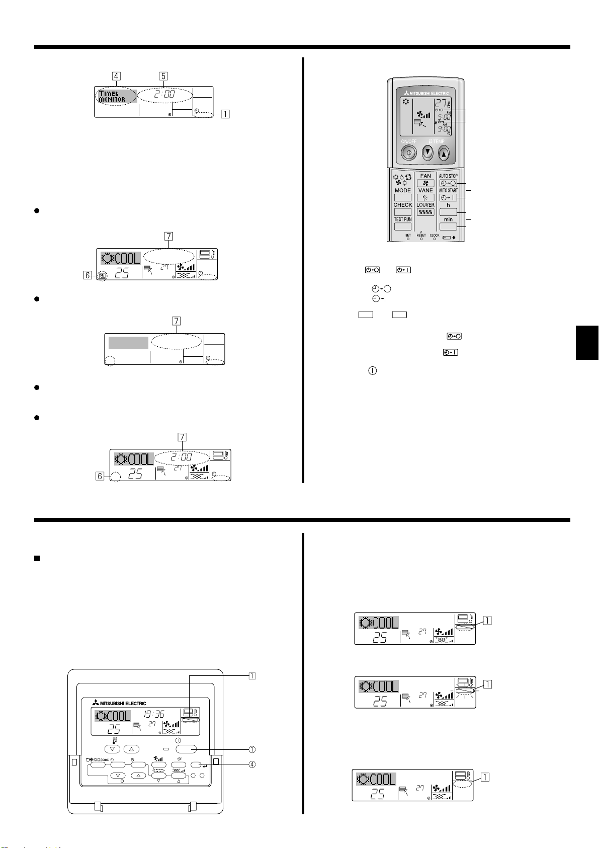
<Checking the Current Auto Off Timer Setting>
Timer Setting
TIMER
AFTER
OFF
AUTOOFF
1. Be sure that the “Auto Off” is visible on the screen (at 1).
2. Hold down the Timer Menu button 2 for 3 seconds so that “Monitor”
is indicated on the screen (at 4).
• The timer remaining to shutdown appears at 5.
3. To close the monitor and return to the standard control screen, press
the Mode (Return) button 2.
<To Turn Off the Auto Off Timer...>
Hold down the Timer On/Off button 9 for 3 seconds so that “Timer
Off” appears (at 6) and the timer value (at 7) disappears.
°C
°C
AUTOOFF
Alternatively, turn off the air conditioner itself. The timer value (at 7)
will disappear from the screen.
AUTOOFF
<To Turn On the Auto Off Timer...>
Hold down the Timer On/Off button 9 for 3 seconds. The “Timer Off”
indication disappears (at 6), and the timer setting comes on the display (at
).
7
Alternatively, turn on the air conditioner. The timer value will appear at 7.
6.2. For Wireless Remote-controller
A
13
2
1 Press the
AUTO STOP
• Time can be set while the following symbol is blinking.
OFF timer : A
ON timer : A is blinking.
2 Use the h and
3 Canceling the timer.
To cancel the OFF timer, press the
To cancel the ON timer, press the
• It is possible to combine both OFF and ON timers.
• Pressing the ON/OFF button of the remote controller during timer
mode to stop the unit will cancel the timers.
• If the current time has not been set, the timer operation cannot be
used.
AUTO START
or
button (TIMER SET).
is blinking.
min
buttons to set the desired time.
AUTO STOP
AUTO START
button.
button.
AFTER OFF
°C
°C
AUTOOFF
7. Other Functions
7.1. Locking the Remote Controller Buttons (Operation
function limit controller)
If you wish, you can lock the remote controller buttons. You can use
the Function Selection of remote controller to select which type of lock
to use. (For information about selecting the lock type, see section 8,
item [4]–2 (1)).
Specifi cally, you can use either of the following two lock types.
Lock All Buttons:
1
Locks all of the buttons on the remote controller.
Lock All Except ON/OFF:
2
Locks all buttons other than the ON/OFF button.
Note:
The “Locked” indicator appears on the screen to indicate that buttons are currently locked.
Lock Indicator
TIME SUN
FUNCTION
ON/OFF
°C
OPERATION
ON/OFF
FILTER
CHECK
CLEAR
TEST
TEMP.
MENU
BACK DAY
MONITOR/SET
PAR-21MAA
CLOCK
°C
<How to Lock the Buttons>
1. While holding down the Filter button 4, press and hold down the ON/
OFF button 1 for 2 seconds. The “Locked” indication appears on the
screen (at 1), indicating that the lock is now engaged.
* If locking has been disabled in Function Selection of remote control-
ler, the screen will display the “Not Available” message when you
press the buttons as described above.
FUNCTION
°C
°C
• If you press a locked button, the “Locked” indication (at 1) will blink
on the display.
<How to Unlock the Buttons>
1. While holding down the Filter button 4, press and hold down the ON/
OFF button 1 for 2 seconds—so that the “Locked” indication disappears from the screen (at 1).
°C
°C
11

7. Other Functions
7.2. Error Codes indication
ERRORCODE
ON/OFF
ON lamp
(Blinking)
Unit No.
Error Code
If you have entered contact number to be called in the event of a problem, the screen displays this number.
(You can set this up under Function Selection of remote controller. For information, refer to section 8.)
If the ON lamp and error code are both blinking: This means that the air conditioner is out of order and operation has been stopped (and cannot
resume). Take note of the indicated unit number and error code, then switch off the power to the air conditioner and call your dealer or servicer.
When the Check button is pressed:
ERRORCODE
°C
If only the error code is blinking (while the ON lamp remains lit): Operation is continuing, but there may be a problem with the system. In this case,
°C
ON/OFF
Error Code
CALL:XXXX
XXX:XXX
ON/OFF
you should note down the error code and then call your dealer or servicer for advice.
* If you have entered contact number to be called in the event of a problem, push the Check button to display it on the screen. (You can set this up
under Function Selection of remote controller. For information, refer to section 8.)
8. Function Selection
Function selection of remote controller
The setting of the following remote controller functions can be changed using the remote controller function selection mode. Change the setting when
needed.
Item 1 Item 2 Item 3 (Setting content)
1. Change Language
(“CHANGE LAN-
GUAGE”)
Language setting to display • Display in multiple languages is possible
2. Function limit
(“FUNCTION SELEC-
TION”)
3. Mode selection
(“MODE SELECTION”)
4. Display change
(“DISP MODE SET-
TING”)
12
(1) Operation function limit setting (operation lock)
• Setting the range of operation limit (operation lock)
(“LOCKING FUNCTION”)
(2) Use of automatic mode setting (“SELECT
• Setting the use or non-use of “automatic” operation mode
AUTO MODE”)
(3) Temperature range limit setting (“LIMIT TEMP
FUNCTION”)
(1) Remote controller main/sub setting (“CON-
TROLLER MAIN/SUB”)
• Setting the temperature adjustable range (maximum, minimum)
• Selecting main or sub remote controller
* When two remote controllers are connected to one group,
one controller must be set to sub.
(2) Use of clock setting (“CLOCK”) • Setting the use or non-use of clock function
(3) Timer function setting (“WEEKLY TIMER”) • Setting the timer type
(4) Contact number setting for error situation
(“CALL.”)
(1) Temperature display °C/°F setting (“TEMP
• Contact number display in case of error
• Setting the telephone number
• Setting the temperature unit (°C or °F) to display
MODE °C/°F”)
(2) Suction air temperature display setting (“ROOM
TEMP DISP SELECT”)
(3) Automatic cooling/heating display setting
(“AUTO MODE DISP C/H”)
• Setting the use or non-use of the display of indoor (suction)
air temperature
• Setting the use or non-use of the display of “Cooling” or
“Heating” display during operation with automatic mode
 Loading...