


Mitsubishi Electronics PLFY-P36, PLFY-P30, PLFY-P24, PLFY-P18, PLFY-P15 User Manual
...SPLIT-TYPE, HEAT PUMP AIR CONDITIONERS
November 2008
No. OCH421
REVISED EDITION-A
TECHNICAL & SERVICE MANUAL
Indoor unit [Model names]
PLFY-P12NBMU-E
PLFY-P15NBMU-E
PLFY-P18NBMU-E
PLFY-P24NBMU-E
PLFY-P30NBMU-E
PLFY-P36NBMU-E
Model name indication
R410A / R22
[Service Ref.]
PLFY-P12NBMU-E PLFY-P12NBMU-ER1 PLFY-P15NBMU-E PLFY-P15NBMU-ER1 PLFY-P18NBMU-E PLFY-P18NBMU-ER1 PLFY-P24NBMU-E PLFY-P24NBMU-ER1 PLFY-P30NBMU-E PLFY-P30NBMU-ER1 PLFY-P36NBMU-E PLFY-P36NBMU-ER1
Revision:
•PLFY-P12/15/18/24/30/36 NBMU-ER1 are added in REVISED EDITION-A.
•Some descriptions have been modified.
•Plase void OCH421.
Note:
•This manual does not cover outdoor units.
When servicing them, please refer to the outdoor unit’s service manual.
•RoHS compliant products have <G> mark on the spec name plate.
CONTENTS
|
1. TECHNICAL CHANGES |
......................... |
|
|||
|
|
|
|
2 |
||
|
2. |
FEATURES............................................. |
2 |
|||
|
3. |
PART NAMES AND FUNCTIONS.......... |
3 |
|||
|
4. |
................................... |
5 |
|||
|
SPECIFICATIONS |
................... |
||||
|
5. |
|
9 |
|||
|
4-WAY AIR FLOW SYSTEM |
|
|
|||
|
6. |
OUTLINES AND DIMENSIONS............12 |
||||
|
|
............................... |
13 |
|||
|
7. WIRING DIAGRAM |
|
|
|||
|
8. REFRIGERANT SYSTEM DIAGRAM |
...... |
|
|||
|
|
14 |
||||
|
|
|
......... |
15 |
||
INDOOR UNIT |
9. MICROPROCESSOR CONTROL |
|
||||
|
......................... |
22 |
||||
|
10. TROUBLESHOOTING |
|
|
|||
|
11. DISASSEMBLY PROCEDURE............. |
31 |
||||
PARTS CATALOG (OCB421)
1 
 TECHNICAL CHANGES
PLFY-P12NBMU-E PLFY-P15NBMU-E PLFY-P18NBMU-E PKFY-P24NBMU-E PKFY-P30NBMU-E PKFY-P36NBMU-E
PLFY-P12NBMU-ER1 PLFY-P15NBMU-ER1 PLFY-P18NBMU-ER1 PLFY-P24NBMU-ER1 PLFY-P30NBMU-ER1 PLFY-P36NBMU-ER1
INDOOR CONTROLLER BOARD (I.B.) has been changed.
2 
 FEATURES
Models |
Cooling capacity / Heating capacity |
PLFY-P12NBMU-E |
12,000 / 13,500 Btu/h |
PLFY-P15NBMU-E |
15,000 / 17,000 Btu/h |
PLFY-P18NBMU-E |
18,000 / 20,000 Btu/h |
PLFY-P24NBMU-E |
24,000 / 27,000 Btu/h |
PLFY-P30NBMU-E |
30,000 / 34,000 Btu/h |
PLFY-P36NBMU-E |
36,000 / 40,000 Btu/h |
Indoor Unit
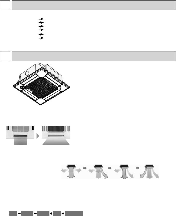
1. WIDE AIRFLOW
The new wide shape vane capable of wide angle air supply provides comfort even at the corners of a room regardless of cooling and heating operation. A reduction in the air speed by 20% compared to the conventional product eliminates uncomfortable draft sensation for friendly air conditioning.
2. WAVE AIRFLOW SYSTEM (HEATING MODE)
The wave airflow system has 4 vanes where each vane runs independently. Repeating of horizontal and down blows with a time lag allows the conditioned warm air to be distributed even to room corners thus preventing uneven room temperature distribution.
Operation image of "Wave Airflow"
3. AUTOMATIC AIR SPEED ADJUSTMENT MODE
The automatic air speed adjustment mode is provided in addition to the 4 air speed stages of "High/Medium 1/Medium 2/ Low." Air speed can be changed freely in accordance with a difference between the set temperature and the room temperature. The automatic air speed adjustment mode presents quick cooling of a room with the high mode, such as at the starting up of cooling operation, for example. After the room temperature is stabilized, the low mode will be applied by automatic switching to keep your comfort.
Low |
Medium 2 |
Medium 1 |
High |
Automatic air |
speed adjustment |
4. i-see Sensor (OPTIONAL CORNER PANEL)
The i see sensor is a radiation temperature sensor originated from Mitsubishi’s new technology. In order to create a really comfortable space in shops and offices, it is essential to control the temperature near the floor where occupants/visitors gather. The i see sensor measures the infrared rays generated from the surrounding wall and floor surface at an angle of 360° and the infrared ray energy is computed to convert it into the value of temperature. In addition, the floor temperature at distant spots (radiation temperature) is also measured to supply the optimum airflow to realize comfort which was never experienced in the past.
2

3 
 PART NAMES AND FUNCTIONS
Indoor unit
Drain pipe
Filter
Air outlet Liquid pipe
Gas pipe
i-see sensor (option)
Vane
Air intake (Intake grille)
 Wired remote controller
Operation Section
Temperature setting buttons |
|
|
|
Down |
|
|
|
Up |
|
|
|
Timer Menu button |
|
|
|
(Monitor/Set button) |
|
|
|
Mode button (Return button) |
|
|
|
|
|
TEMP. |
|
Set Time buttons |
|
|
|
Back |
|
MENU |
ON/OFF |
Ahead |
BACK |
MONITOR/SET |
DAY |
|
|||
Timer On/Off button |
PAR-21MAA |
CLOCK |
|
(Set Day button) |
|
|
|
Opening the |
|
|
|
lid |
|
|
|
|
ON/OFF |
|
|
FILTER |
|
|
CHECK |
TEST |
OPERATION |
CLEAR |
|
Built-in temperature sensor
ON/OFF button
Fan Speed button
Filter  button (<Enter> button)
Test Run button
Check button (Clear button)
Airflow Up/Down button
Louver button
( Operation button)
To return operation number
Ventilation button
( Operation button)
To go to next operation number
3

 Wired remote controller
Display Section
For purposes of this explanation, |
Day-of-Week |
|
all parts of the display are shown |
Shows the current day of the week. |
|
as lit. During actual operation, only |
Time/Timer Display |
|
the relevant items will be lit. |
||
|
Shows the current time, unless the simple or Auto Off |
|
|
timer is set. |
|
|
If the simple or Auto Off timer is set, the time to be |
|
|
switched off is shown. |
|
Identifies the current operation
Shows the operating mode, etc. *Multilanguage display is available.
“Centrally Controlled” indicator
Indicates that operation from the remote controller has been prohibited by a master controller.
“Timer is Off” indicator
Indicates that the timer is off.
Temperature Setting
Shows the target temperature.
TIME SUN MON TUE WED THU FRI SAT |
||
TIMER |
Hr |
ON |
AFTER |
AFTER |
OFF |
ERROR CODE |
|
FUNCTION |
°F°C |
|
FILTER |
°F°C |
|
|
|
WEEKLY |
|
ONLY1Hr. |
|
SIMPLE |
|
AUTO OFF |
|
Up/Down Air Direction indicator
The indicator shows the direction of the outcoming airflow.
“One Hour Only” indicator
Displayed if the airflow is set to Low or downward during COOL or DRY mode. (Operation varies according to model.)
The indicator goes off in one hour, at which time the airflow direction also changes.
Room Temperature display
Shows the room temperature. The room temperature display range is 46–102F. The display blinks if the temperature is less than 46F or 102F or more.
Louver display
Indicates the action of the swing louver. Does not appear if the louver is not running.
 (Power On indicator)
Indicates that the power is on.
“Sensor” indication
Displayed when the remote controller sensor is used.
“Locked” indicator
Indicates that remote controller buttons have been locked.
“Clean The Filter” indicator
To be displayed on when it is time to clean the filter.
Timer indicators
The indicator comes on if the corresponding timer is set.
Fan Speed indicator
Shows the selected fan speed.
Ventilation indicator
Appears when the unit is running in Ventilation mode.
Note:
●“PLEASE WAIT” message
This message is displayed for approximately 3 minutes when power is supplied to the indoor unit or when the unit is recovering from a power failure.
●“NOT AVAILABLE” message
This message is displayed if an invalid button is pressed (to operate a function that the indoor unit does not have).
If a single remote controller is used to operate multiple indoor units simultaneously that are different types, this message will not be displayed as far as any of the indoor units is equipped with the function.
4

4 |
|
|
SPECIFICATIONS |
|
|
|
|
|
||||||
4-1. SPECIFICATIONS |
|
|
|
|
|
|
|
|
||||||
Model |
|
|
|
|
|
PLFY-P12NBMU-E |
PLFY-P15NBMU-E |
PLFY-P18NBMU-E |
||||||
|
|
|
|
|
PLFY-P12NBMU-ER1 |
PLFY-P15NBMU-ER1 |
PLFY-P18NBMU-ER1 |
|||||||
|
|
|
|
|
|
|
|
|||||||
Power source |
|
|
|
|
BTU/h |
|
|
|
1-phase 208-230V 60Hz |
|
|
|||
Cooling capacity |
|
|
*1 |
|
12,000 |
|
15,000 |
|
18,000 |
|
||||
(Nominal) |
|
|
|
*1 |
kW |
|
3.5 |
|
4.4 |
|
5.3 |
|
||
|
|
|
|
Power input |
kW |
|
0.03 |
|
0.04 |
|
0.05 |
|
||
|
|
|
|
Current input |
A |
|
0.22 |
|
0.29 |
|
0.36 |
|
||
Heating capacity |
|
|
*2 |
Btu/h |
|
13,500 |
|
17,000 |
|
20,000 |
|
|||
(Nominal ) |
|
|
|
*2 |
kcal/h |
|
4.0 |
|
5.0 |
|
5.9 |
|
||
|
|
|
|
Power input |
kW |
|
0.02 |
|
0.03 |
|
0.04 |
|
||
|
|
|
|
Current input |
A |
|
0.14 |
|
0.22 |
|
0.29 |
|
||
External finish |
|
|
|
|
|
|
|
|
Galvanized steel sheet |
|
|
|||
External dimension H × W × D |
|
|
in. |
10-3/16 × 33-3/32 × 33-3/32 |
10-3/16 × 33-3/32 × 33-3/32 |
10-3/16 × 33-3/32 × 33-3/32 |
||||||||
|
|
|
|
|
|
|
mm |
258 × 840 × 840 |
258 × 840 × 840 |
258 × 840 × 840 |
||||
Net weight |
|
|
|
|
Ibs (kg) |
|
49 (22) |
49 (22) |
51 (23) |
|||||
Decoration panel |
Model |
|
|
|
|
PLP-40BAU |
PLP-40BAU |
PLP-40BAU |
||||||
|
|
|
|
External finish |
|
|
|
|
MUNSELL (6.4Y 8.9/0.4) |
|
|
|||
|
|
|
|
Dimension |
|
in. |
1-3/8 × 37-13/32 × 37-13/32 |
1-3/8 × 37-13/32 × 37-13/32 |
1-3/8 × 37-13/32 × 37-13/32 |
|||||
|
|
|
|
H × W × D |
|
mm |
|
35 × 950 × 950 |
35 × 950 × 950 |
35 × 950 × 950 |
||||
|
|
|
|
Net weight |
|
Ibs (kg) |
|
13 (6) |
|
13 (6) |
|
13 (6) |
|
|
Heat exchanger |
|
|
|
|
|
|
|
Cross fin |
|
|
||||
FAN |
|
Type x Quantity |
|
|
Turbo fan × 1 |
Turbo fan × 1 |
Turbo fan × 1 |
|||||||
|
|
|
|
External |
|
|
in.WG |
|
0.000 (208V) |
0.000 (208V) |
0.000 (208V) |
|||
|
|
|
|
static press. |
|
Pa |
|
0 |
|
0 |
|
0 |
|
|
|
|
|
|
|
|
|
in.WG |
|
0.000 (230V) |
0.000 (230V) |
0.000 (230V) |
|||
|
|
|
|
|
|
|
Pa |
|
0 |
|
0 |
|
0 |
|
|
|
|
|
Motor type |
|
|
|
|
|
DC motor |
|
|
||
|
|
|
|
Motor output |
kW |
|
0.050 |
|
0.050 |
|
0.050 |
|
||
|
|
|
|
Driving mechanism |
|
|
|
|
Direct-drive |
|
|
|||
|
|
|
|
Airflow rate |
|
cfm |
388 - 424 - 459 - 494 |
424 - 459 - 494 - 565 |
494 - 530 - 565 - 636 |
|||||
|
|
|
|
(Low-Mid2- |
|
m3/min |
11.0 - 12.0 - 13.0 - 14.0 |
12.0 - 13.0 - 14.0 - 16.0 |
14.0 - 15.0 - 16.0 - 18.0 |
|||||
|
|
|
|
Mid1-High) |
|
L / s |
183 - 200 - 217 - 233 |
200 - 217 - 233 - 267 |
233 - 250 - 267 - 300 |
|||||
Noise level (Low-Mid2-Mid1-High) |
dB <A> |
27 - 28 - 29 - 31 (208-230V) |
27 - 28 - 30 - 31 (208-230V) |
28 - 29 - 3032 (208-230V) |
||||||||||
(measured in anechoic room) |
|
|
dB <A> |
|
— |
|
— |
|
— |
|
||||
|
|
|
|
|
|
|
dB <A> |
|
— |
|
— |
|
— |
|
|
|
|
|
|
|
|
|
|
|
|
|
|
|
|
Insulation material |
|
|
|
|
|
|
|
PS |
|
|
|
|||
Air filter |
|
|
|
|
|
|
|
PP honeycomb (long life filter, anti-bacterial type) |
|
|||||
Protection device |
|
|
|
|
|
|
|
Fuse |
|
|
|
|||
Refrigerant control device |
|
|
|
|
|
|
LEV |
|
|
|
||||
Connectable outdoor unit |
|
|
|
|
|
|
R410A, R22 CITY MULTI |
|
|
|||||
Diameter of |
|
Liquid |
(R410A) |
in. (mm) |
1/4 (6.35) |
Flare |
1/4 (6.35) |
Flare |
1/4 (6.35) |
Flare |
||||
refrigerant pipe |
|
|
(R22) |
|
1/4 (6.35) |
Flare |
1/4 (6.35) |
Flare |
3/8 (9.52) |
Flare |
||||
(O.D.) |
|
Gas |
(R410A) |
in. (mm) |
1/2 (12.7) |
Flare |
1/2 (12.7) |
Flare |
1/2 (12.7) |
Flare |
||||
|
|
|
|
|||||||||||
|
|
|
|
|
|
(R22) |
|
1/2 (12.7) |
Flare |
1/2 (12.7) |
Flare |
5/8 (15.88) |
Flare |
|
Field drain pipe size |
|
|
in. (mm) |
|
O.D. 1-1/4 (32) |
O.D. 1-1/4 (32) |
O.D. 1-1/4 (32) |
|||||||
Standard |
|
Document |
|
|
|
|
|
Installation Manual, Instruction Book |
|
|
||||
attachment |
|
Accessory |
|
|
|
|
|
|
|
|||||
Optional parts |
|
Air outlet shutter plate |
PAC-SH51SP-E |
PAC-SH51SP-E |
PAC-SH51SP-E |
|||||||||
|
|
|
|
High efficiency filterelement |
PAC-SH59KF-E |
PAC-SH59KF-E |
PAC-SH59KF-E |
|||||||
|
|
|
|
Multi-function casement |
PAC-SH53TM-E |
PAC-SH53TM-E |
PAC-SH53TM-E |
|||||||
Remark |
|
|
|
|
|
|
|
|
|
|
|
|
||
|
|
|
|
Installation |
|
|
Details on foundation work, duct work, insulation work, electrical wiring, power source switch, and other items |
|||||||
|
|
|
|
|
|
|
|
shall be referred to the Installation Manual. |
|
|
|
|||
Note: |
|
|
*1 Nominal cooling conditions |
*2 Nominal heating conditions |
|
Unit converter |
||||||||
|
|
|
|
|
||||||||||
|
|
|
|
Indoor : 80degF D.B. / 67degF W.B. |
70degF D.B. |
|
|
kcal/h = kW × 860 |
||||||
|
|
|
|
|
|
(26.7degC D.B. / 19.4degC W.B.) (21.1degC D.B.) |
|
|
||||||
|
|
|
|
|
|
|
|
BTU/h = kW × 3,412 |
||||||
|
|
|
|
Outdoor : 95degF D.B. |
|
47degF D.B. / 43degF W.B. |
|
|||||||
|
|
|
|
|
|
cfm = m3/min × 35.31 |
||||||||
|
|
|
|
|
|
(35degC D.B.) |
|
(8.3degC D.B. / 6.1degC W.B.) |
|
|||||
|
|
|
|
|
|
|
|
lbs = kg/0.4536 |
||||||
|
|
|
|
Pipe length : |
25 ft. (7.6 m) |
|
25 ft. (7.6 m) |
|
|
|||||
|
|
|
|
|
|
|
|
|
||||||
|
|
|
Level difference : |
0 ft. (0 m) |
|
0 ft. (0 m) |
|
|
|
|
||||
|
*Above specification |
|
data is subject to |
*Due to continuing improvement, above specification may be subject to change without notice. |
rounding variation. |
|
5
|
|
|
|
|
|
|
|
|
|
|
|
Model |
|
|
|
|
PLFY-P24NBMU-E |
PLFY-P30NBMU-E |
PLFY-P36NBMU-E |
||||
|
|
|
|
PLFY-P24NBMU-ER1 |
PLFY-P30NBMU-ER1 |
PLFY-P36NBMU-ER1 |
|||||
|
|
|
|
|
|||||||
Power source |
|
|
|
BTU/h |
|
|
|
1-phase 208-230V 60Hz |
|
|
|
Cooling capacity |
|
|
*1 |
24,000 |
|
30,000 |
|
36,000 |
|
||
(Nominal) |
|
|
*1 |
kW |
7.0 |
|
|
8.8 |
|
10.5 |
|
|
Power input |
kW |
0.06 |
|
0.07 |
|
0.16 |
|
|||
|
Current input |
A |
0.43 |
|
0.51 |
|
1.07 |
|
|||
Heating capacity |
|
|
*2 |
Btu/h |
27,000 |
|
34,000 |
|
40,000 |
|
|
(Nominal ) |
|
|
*2 |
kcal/h |
7.9 |
|
|
10.0 |
|
11.7 |
|
|
Power input |
kW |
0.05 |
|
0.06 |
|
0.15 |
|
|||
|
Current input |
A |
0.36 |
|
0.43 |
|
1.00 |
|
|||
External finish |
|
|
|
|
|
|
|
Galvanized steel sheet |
|
|
|
External dimension H × W × D |
|
|
in. |
10-3/16 × 33-3/32 × 33-3/32 |
10-3/16 × 33-3/32 × 33-3/32 |
11-3/4 × 33-3/32 × 33-3/32 |
|||||
|
|
|
|
mm |
258 × 840 × 840 |
258 × 840 × 840 |
298 × 840 × 840 |
||||
Net weight |
|
|
|
Ibs (kg) |
51 (23) |
51 (23) |
60 (27) |
||||
Decoration panel |
Model |
|
|
|
PLP-40BAU |
PLP-40BAU |
PLP-40BAU |
||||
|
External finish |
|
|
|
|
MUNSELL (6.4Y 8.9/0.4) |
|
|
|||
|
Dimension |
|
in. |
1-3/8 × 37-13/32 × 37-13/32 |
1-3/8 × 37-13/32 × 37-13/32 |
1-3/8 × 37-13/32 × 37-13/32 |
|||||
|
H × W × D |
|
mm |
35 × 950 × 950 |
35 × 950 × 950 |
35 × 950 × 950 |
|||||
|
Net weight |
|
Ibs (kg) |
13 (6) |
|
13 (6) |
|
13 (6) |
|
||
Heat exchanger |
|
|
|
|
|
|
|
Cross fin |
|
|
|
FAN |
Type × Quantity |
|
Turbo fan × 1 |
Turbo fan × 1 |
Turbo fan × 1 |
||||||
|
External |
|
|
in.WG |
0.000 (208V) |
0.000 (208V) |
0.000 (208V) |
||||
|
static press. |
|
Pa |
0 |
|
|
0 |
|
0 |
|
|
|
|
|
|
in.WG |
0.000 (230V) |
0.000 (230V) |
0.000 (230V) |
||||
|
|
|
|
Pa |
0 |
|
|
0 |
|
0 |
|
|
Motor type |
|
|
|
|
|
DC motor |
|
|
||
|
Motor output |
kW |
0.050 |
|
0.050 |
|
0.120 |
|
|||
|
Driving mechanism |
|
|
|
|
Direct-drive |
|
|
|||
|
Airflow rate |
|
cfm |
530 - 565 - 636 - 706 |
565 - 636 - 706 - 777 |
777 - 883 - 989 - 1,059 |
|||||
|
(Low-Mid2- |
|
m3/min |
15.0 - 16.0 - 18.0 -20.0 |
16.0 - 18.0 - 20.0 - 22.0 |
22.0 - 25.0 - 28.0 - 30.0 |
|||||
|
Mid1-High) |
|
L/s |
250 - 267 - 300 - 333 |
267 - 300 - 333 - 367 |
367 - 417 - 467 - 500 |
|||||
Noise level (Low-Mid2-Mid1-High) |
dB <A> |
28 - 30 - 32 - 34 (208-230V) |
30 - 32 - 35 - 37 (208-230V) |
35 - 38 - 41 - 43 (208-230V) |
|||||||
(measured in anechoic room) |
|
|
dB <A> |
— |
|
|
— |
|
— |
|
|
|
|
|
|
dB <A> |
— |
|
|
— |
|
— |
|
|
|
|
|
|
|
|
|
|
|
|
|
Insulation material |
|
|
|
|
|
|
|
PS |
|
|
|
Air filter |
|
|
|
|
|
|
PP honeycomb (long life filter, anti-bacterial type) |
|
|||
Protection device |
|
|
|
|
|
|
|
Fuse |
|
|
|
Refrigerant control device |
|
|
|
|
|
|
LEV |
|
|
|
|
Connectable outdoor unit |
|
|
|
|
|
|
R410A, R22 CITY MULTI |
|
|
||
Diameter of |
Liquid |
(R410A) |
in. (mm) |
3/8 (9.52) |
|
Flare |
3/8 (9.52) |
Flare |
3/8 (9.52) |
Flare |
|
refrigerant pipe |
|
|
(R22) |
|
3/8 (9.52) |
|
Flare |
3/8 (9.52) |
Flare |
3/8 (9.52) |
Flare |
(O.D.) |
Gas |
(R410A) |
in. (mm) |
5/8 (15.88) |
Flare |
5/8 (15.88) |
Flare |
5/8 (15.88) |
Flare |
||
|
|||||||||||
|
|
|
(R22) |
|
5/8 (15.88) |
Flare |
5/8 (15.88) |
Flare |
3/4 (19.05) |
Flare |
|
Field drain pipe size |
|
|
in. (mm) |
O.D. 1-1/4 (32) |
O.D. 1-1/4 (32) |
O.D. 1-1/4 (32) |
|||||
Standard |
Document |
|
|
|
|
|
Installation Manual, Instruction Book |
|
|
||
attachment |
Accessory |
|
|
|
|
|
|
|
|||
|
|
|
|
|
|
|
|
|
|||
Optional parts |
Air outlet shutter plate |
PAC-SH51SP-E |
PAC-SH51SP-E |
PAC-SH51SP-E |
|||||||
|
High efficiency filterelement |
PAC-SH59KF-E |
PAC-SH59KF-E |
PAC-SH59KF-E |
|||||||
|
Multi-function casement |
PAC-SH53TM-E |
PAC-SH53TM-E |
PAC-SH53TM-E |
|||||||
Remark |
|
|
|
|
|
|
|
|
|
|
|
|
Installation |
|
|
Details on foundation work, duct work, insulation work, electrical wiring, power source switch, and other items |
|||||||
|
|
|
|
|
shall be referred to the Installation Manual. |
|
|
|
|||
Note: |
|
*1 Nominal cooling conditions |
*2 Nominal heating conditions |
|
Unit converter |
||||||
|
|
|
|
||||||||
|
Indoor : 80degF D.B. / 67degF W.B. |
70degF D.B. |
|
|
kcal/h = kW × 860 |
||||||
|
|
|
(26.7degC D.B. / 19.4degC W.B.) |
(21.1degC D.B.) |
|
|
|||||
|
|
|
|
|
BTU/h = kW × 3,412 |
||||||
|
Outdoor : 95degF D.B. |
|
47degF D.B. / 43degF W.B. |
|
|||||||
|
|
|
cfm = m3/min × 35.31 |
||||||||
|
|
|
(35degC D.B.) |
|
(8.3degC D.B. / 6.1degC W.B.) |
|
|||||
|
|
|
|
|
lbs = kg/0.4536 |
||||||
|
Pipe length : |
25 ft. (7.6 m) |
|
25 ft. (7.6 m) |
|
|
|||||
|
|
|
|
|
|
||||||
Level difference : |
0 ft. (0 m) |
|
0 ft. (0 m) |
|
|
|
|
||||
|
*Above specification |
|
data is subject to |
*Due to continuing improvement, above specification may be subject to change without notice. |
rounding variation. |
|
6

4-2. SOUND LEVEL
PLFY-P-NBMU-E
5 ft (1.5m)
Measurement location
* Measured in anechoic room.
Sound level at anechoic room : Low-Mid2-Mid1-High
|
Sound level dB (A) |
|
PLFY-P12NBMU-E |
27-28-29-31 |
|
PLFY-P12NBMU-ER1 |
||
|
||
PLFY-P15NBMU-E |
27-28-30-31 |
|
PLFY-P15NBMU-ER1 |
||
|
||
PLFY-P18NBMU-E |
28-29-30-32 |
|
PLFY-P18NBMU-ER1 |
||
PLFY-P24NBMU-E |
28-30-32-34 |
|
PLFY-P24NBMU-ER1 |
||
|
|
|
PLFY-P30NBMU-E |
30-32-35-37 |
|
PLFY-P30NBMU-ER1 |
||
|
||
PLFY-P36NBMU-E |
35-38-41-43 |
|
PLFY-P36NBMU-ER1 |
||
|
4-3. NC CURVES |
|
|
|
|
|
|
|
|
|
|
|
|
|
|
|
|
|
|
|
|
|
|||||
PLFY-P12NBMU-E |
|
|
|
|
|
PLFY-P15NBMU-E |
|
|
|
|
PLFY-P18NBMU-E |
|
|
|
|
|||||||||||
PLFY-P12NBMU-ER1 |
|
|
|
|
PLFY-P15NBMU-ER1 |
|
|
|
|
PLFY-P18NBMU-ER1 |
|
|
|
|
||||||||||||
External static pressure : 0Pa |
|
|
|
External static pressure : 0Pa |
|
|
|
External static pressure : 0Pa |
|
|
|
|||||||||||||||
Power source : 208,230V, 60Hz |
|
|
Power source : 208,230V, 60Hz |
|
|
Power source : 208,230V, 60Hz |
|
|
||||||||||||||||||
|
|
|
|
High 60Hz |
|
Middle1 60Hz |
|
|
|
|
High |
60Hz |
|
Middle1 60Hz |
|
|
|
|
High |
60Hz |
|
Middle1 60Hz |
||||
|
70.0 |
|
|
Low |
60Hz |
|
Middle2 60Hz |
|
70.0 |
|
|
Low |
60Hz |
|
Middle2 60Hz |
|
70.0 |
|
|
Low |
60Hz |
|
Middle2 60Hz |
|||
0dB=20Pa |
|
|
|
|
|
|
|
0dB=20Pa |
|
|
|
|
|
|
|
0dB=20Pa |
|
|
|
|
|
|
|
|||
65.0 |
|
|
|
|
|
|
|
65.0 |
|
|
|
|
|
|
|
65.0 |
|
|
|
|
|
|
|
|||
60.0 |
|
|
|
|
|
|
NC-60 |
60.0 |
|
|
|
|
|
|
NC-60 |
60.0 |
|
|
|
|
|
|
NC-60 |
|||
55.0 |
|
|
|
|
|
|
55.0 |
|
|
|
|
|
|
55.0 |
|
|
|
|
|
|
||||||
|
|
|
|
|
|
|
|
|
|
|
|
|
|
|
|
|
|
|
|
|
||||||
(dB) |
50.0 |
|
|
|
|
|
|
NC-50 |
(dB) |
50.0 |
|
|
|
|
|
|
NC-50 |
(dB) |
50.0 |
|
|
|
|
|
|
NC-50 |
|
|
|
|
|
|
|
|
|
|
|
|
|
|
|
|
|
|
|
|
|
||||||
level |
45.0 |
|
|
|
|
|
|
level |
45.0 |
|
|
|
|
|
|
level |
45.0 |
|
|
|
|
|
|
|||
|
|
|
|
|
|
|
|
|
|
|
|
|
|
|
|
|
|
|
|
|
||||||
40.0 |
|
|
|
|
|
|
|
40.0 |
|
|
|
|
|
|
|
40.0 |
|
|
|
|
|
|
|
|||
pressure |
|
|
|
|
|
|
NC-40 |
pressure |
|
|
|
|
|
|
NC-40 |
pressure |
|
|
|
|
|
|
NC-40 |
|||
35.0 |
|
|
|
|
|
|
35.0 |
|
|
|
|
|
|
35.0 |
|
|
|
|
|
|
||||||
|
|
|
|
|
|
|
|
|
|
|
|
|
|
|
|
|
|
|
|
|
||||||
30.0 |
|
|
|
|
|
|
|
30.0 |
|
|
|
|
|
|
|
30.0 |
|
|
|
|
|
|
NC-30 |
|||
band |
25.0 |
|
|
|
|
|
|
NC-30 |
band |
25.0 |
|
|
|
|
|
|
NC-30 |
band |
25.0 |
|
|
|
|
|
|
|
|
|
|
|
|
|
|
|
|
|
|
|
|
|
|
|
|
|
|
||||||||
|
|
|
|
|
|
|
|
|
|
|
|
|
|
|
|
20.0 |
|
|
|
|
|
|
|
|||
Octave |
20.0 |
Approximate minimum |
|
|
|
|
|
Octave |
20.0 |
Approximate minimum |
|
|
|
|
|
Octave |
Approximate minimum |
|
|
|
|
NC-20 |
||||
15.0 |
audible limit on |
|
|
|
|
|
NC-20 |
15.0 |
audible limit on |
|
|
|
|
|
NC-20 |
15.0 |
audible limit on |
|
|
|
|
|
||||
continuous noise |
|
|
|
|
|
continuous noise |
|
|
|
|
10.0 |
continuous noise |
|
|
|
|
|
|||||||||
|
10.0 |
125 |
250 |
500 |
1k |
2k |
4k |
8k |
|
10.0 |
125 |
250 |
500 |
1k |
2k |
4k |
8k |
|
125 |
250 |
500 |
1k |
2k |
4k |
8k |
|
|
63 |
|
63 |
|
63 |
|||||||||||||||||||||
Octave band center frequencies (Hz) |
Octave band center frequencies (Hz) |
Octave band center frequencies (Hz)
PLFY-P24NBMU-E
PLFY-P24NBMU-ER1
External static pressure : 0Pa
Power source : 208,230V, 60Hz
|
|
|
|
High |
60Hz |
|
Middle1 60Hz |
|
|
70.0 |
|
|
Low |
60Hz |
|
Middle2 60Hz |
|
0dB=20Pa |
|
|
|
|
|
|
|
|
55.0 |
|
|
|
|
|
|
|
|
|
65.0 |
|
|
|
|
|
|
|
|
60.0 |
|
|
|
|
|
|
NC-60 |
(dB) |
|
|
|
|
|
|
|
|
50.0 |
|
|
|
|
|
|
NC-50 |
|
|
|
|
|
|
|
|
||
level |
45.0 |
|
|
|
|
|
|
|
|
|
|
|
|
|
|
||
|
|
|
|
|
|
|
|
|
pressure |
40.0 |
|
|
|
|
|
|
NC-40 |
30.0 |
|
|
|
|
|
|
||
|
35.0 |
|
|
|
|
|
|
|
band |
25.0 |
|
|
|
|
|
|
NC-30 |
|
|
|
|
|
|
|
||
|
|
|
|
|
|
|
|
|
Octave |
20.0 |
continuous noise |
|
|
|
|
|
|
|
|
Approximate minimum |
|
|
|
|
NC-20 |
|
|
15.0 |
audible limit on |
|
|
|
|
|
|
|
10.0 |
125 |
250 |
500 |
1k |
2k |
4k |
8k |
|
63 |
|||||||
Octave band center frequencies (Hz)
PLFY-P30NBMU-E
PLFY-P30NBMU-ER1
External static pressure : 0Pa
Power source : 208,230V, 60Hz
|
|
|
|
High |
60Hz |
|
Middle1 60Hz |
|
|
70.0 |
|
|
Low |
60Hz |
|
Middle2 60Hz |
|
0dB=20Pa |
|
|
|
|
|
|
|
|
55.0 |
|
|
|
|
|
|
|
|
|
65.0 |
|
|
|
|
|
|
|
|
60.0 |
|
|
|
|
|
|
NC-60 |
(dB) |
|
|
|
|
|
|
|
|
50.0 |
|
|
|
|
|
|
NC-50 |
|
|
|
|
|
|
|
|
||
level |
45.0 |
|
|
|
|
|
|
|
|
|
|
|
|
|
|
||
|
|
|
|
|
|
|
|
|
pressure |
40.0 |
|
|
|
|
|
|
NC-40 |
30.0 |
|
|
|
|
|
|
||
|
35.0 |
|
|
|
|
|
|
|
band |
25.0 |
|
|
|
|
|
|
NC-30 |
|
|
|
|
|
|
|
|
|
Octave |
20.0 |
continuous noise |
|
|
|
|
|
|
|
|
Approximate minimum |
|
|
|
|
NC-20 |
|
|
15.0 |
audible limit on |
|
|
|
|
|
|
|
10.0 |
125 |
250 |
500 |
1k |
2k |
4k |
8k |
|
63 |
|||||||
Octave band center frequencies (Hz)
PLFY-P36NBMU-E
PLFY-P36NBMU-ER1
External static pressure : 0Pa
Power source : 208,230V, 60Hz
|
|
|
|
High |
60Hz |
|
Middle1 60Hz |
|
|
70.0 |
|
|
Low |
60Hz |
|
Middle2 60Hz |
|
0dB=20Pa |
|
|
|
|
|
|
|
|
55.0 |
|
|
|
|
|
|
|
|
|
65.0 |
|
|
|
|
|
|
|
|
60.0 |
|
|
|
|
|
|
NC-60 |
(dB) |
|
|
|
|
|
|
|
|
50.0 |
|
|
|
|
|
|
NC-50 |
|
|
|
|
|
|
|
|
||
level |
45.0 |
|
|
|
|
|
|
|
|
|
|
|
|
|
|
|
|
pressure |
40.0 |
|
|
|
|
|
|
NC-40 |
30.0 |
|
|
|
|
|
|
||
|
35.0 |
|
|
|
|
|
|
|
band |
25.0 |
|
|
|
|
|
|
NC-30 |
|
|
|
|
|
|
|
||
|
|
|
|
|
|
|
|
|
Octave |
20.0 |
continuous noise |
|
|
|
|
|
|
|
15.0 |
Approximate minimum |
|
|
|
|
NC-20 |
|
|
audible limit on |
|
|
|
|
|
||
|
10.0 |
125 |
250 |
500 |
1k |
2k |
4k |
8k |
|
63 |
|||||||
Octave band center frequencies (Hz)
7

4-4. ELECTRICAL PARTS SPECIFICATIONS
Service Ref. |
Symbol |
PLFY-P12NBMU-E |
PLFY-P15NBMU-E |
PLFY-P18NBMU-E |
PLFY-P24NBMU-E |
PLFY-P30NBMU-E |
PLFY-P36NBMU-E |
||
|
|||||||||
Parts name |
|
PLFY-P12NBMU-ER1 |
PLFY-P15NBMU-ER1 |
PLFY-P18NBMU-ER1 |
PLFY-P24NBMU-ER1 |
PLFY-P30NBMU-ER1 |
PLFY-P36NBMU-ER1 |
||
|
|
|
|
|
|
|
|
||
Room temperature |
TH21 |
Resistance 30"F/15.8k , 50"F/9.6k , 70"F/6.0k , 80"F/4.8k , 90"F/3.9k , 100"F/3.2k |
|||||||
thermistor |
|||||||||
|
|
|
|
|
|
|
|
||
|
|
|
|
|
|
|
|
||
Liquid pipe thermistor |
TH22 |
Resistance 30"F/15.8k , 50"F/9.6k , 70"F/6.0k , 80"F/4.8k , 90"F/3.9k , 100"F/3.2k |
|||||||
|
|
|
|
|
|
|
|
||
Gas pipe thermistor |
TH23 |
Resistance 30"F/15.8k , 50"F/9.6k , 70"F/6.0k , 80"F/4.8k , 90"F/3.9k , 100"F/3.2k |
|||||||
|
|
|
|
|
|
|
|
|
|
Fuse |
FUSE |
|
|
|
250V 6.3A |
|
|
||
(Indoor controller board) |
|
|
|
|
|
||||
|
|
|
|
|
|
|
|
||
|
|
|
|
|
|
|
|
|
|
Fan motor |
MF |
|
8-pole OUTPUT 50W |
|
8-pole OUTPUT, |
||||
|
|
120W |
|||||||
|
|
|
|
|
|
|
|
||
|
|
|
|
|
|
|
|
||
Vane motor |
MV |
|
|
MSBPC20M04 |
|
|
|||
|
|
DC12V 300 /phase |
|
|
|||||
|
|
|
|
|
|
||||
|
|
|
|
|
|
|
|
||
Drain-up mechanism |
DP |
|
|
PLD-12230ME-1 |
|
|
|||
|
|
INPUT 12/10.8W 24 /Hr |
|
|
|||||
|
|
|
|
|
|
||||
|
|
|
|
|
|
|
|
||
Drain float swich |
FS |
|
|
Open/short detection |
|
|
|||
|
|
|
|
|
|
|
|
|
|
|
|
DC12V Stepping motor drive port dimension |
:3.2 (0~2000pulse) |
DC12V Stepping motor drive port |
|||||
Linear expansion valve |
LEV |
dimension :5.2 (0~2000pulse) |
|||||||
|
EDM-40YGME |
|
|
||||||
|
|
|
|
|
EDM-80YGME |
||||
|
|
|
|
|
|
|
|||
Power supply terminal |
TB2 |
|
|
(L1, L2, GR) 330V 30A |
|
|
|||
block |
|
|
|
|
|||||
|
|
|
|
|
|
|
|
||
|
|
|
|
|
|
|
|
|
|
Transmission terminal |
TB5 |
|
|
(M1, M2, S) 250V 20A |
|
|
|||
block |
|
|
|
|
|||||
|
|
|
|
|
|
|
|
||
|
|
|
|
|
|
|
|
|
|
MA remote controller |
TB15 |
|
|
(1, 2) 250V 10A |
|
|
|||
terminal block |
|
|
|
|
|||||
|
|
|
|
|
|
|
|
||
|
|
|
|
|
|
|
|
|
|
8
5 
 4-WAY AIR FLOW SYSTEM
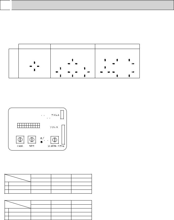
5-1. PLACEMENT OF THE AIR OUTLETS
•For this grille, the blowout direction comes in 11 patterns.
Also, by setting the remote controller to the appropriate settings, you can adjust the air flow and speed. Select the settings from Table1 according to the location in which you want to install the unit.
1) Decide on the pattern of the airflow direction.
<Table 1>
Blowout direction pattern
4-direction |
|
|
3-direction |
|
|
|
|
|
2-direction |
|
||||||||
|
|
Initial setting |
|
One air outlet |
|
|
|
|
2 air outlet |
|
||||||||
Pattern 1 |
|
Pattern 4 |
|
|
|
Pattern 6 |
|
|||||||||||
|
|
|
|
|
|
fully closed |
|
|
|
|
|
fully closed |
|
|||||
|
|
|
|
|
|
|
|
|
|
|
|
|
|
|
|
|
|
|
|
|
|
|
|
|
|
|
|
|
|
|
|
|
|
|
|
|
|
|
|
|
|
|
|
|
|
|
|
|
|
|
|
|
|
|
|
|
|
|
|
|
|
|
|
|
|
|
|
|
|
|
|
|
|
|
|
|
|
|
|
|
|
|
|
|
|
|
|
|
|
|
|
|
|
|
|
|
|
|
|
|
|
|
|
|
|
|
|
|
|
|
|
|
|
|
|
|
|
|
|
|
|
|
|
|
|
|
|
|
|
|
|
|
Note: For 3 and 2-direction settings, please use the air outlet shutter plate (option).
2) According to the number of air outlets and height of the ceiling to install the unit, be sure to set up the switches (SWA, SWB) on the address board to the appropriate setting.
• Correspondence of ceiling heights to numbers of air outlets
SWA SWB |
|
||||
3 |
|
2 |
|
|
|
|
|
||||
2 |
|
3 |
|
|
CN43 |
1 |
|
4 |
|
|
|
SW1 |
|
|
|
|
|
|
|
|
|
|
|
|
|
|
|
|
|
ON
OFF
1 2 3 4 5 6 7 8 9 10
SW12 SW11
9 |
0 |
1 |
9 |
0 |
1 |
8 |
|
2 |
8 |
|
2 |
7 |
|
3 |
7 |
|
3 |
6 |
5 |
4 |
6 |
5 |
4 |
|
|
|
|
||
(10ths DIGIT) |
(1s DIGIT) |
||||
CN82
SWC SW14
|
|
|
F0 |
1 |
|
||
|
D |
E |
|
|
|
2 |
|
|
|
|
|
3 |
|||
|
|
|
|
|
|
4 |
|
|
C |
|
|
|
|
5 |
|
|
B |
|
|
|
6 |
||
|
|
A |
9 |
|
7 |
|
|
|
|
|
|
8 |
|
||
. / . (BRANCH No.)
PLFY-P12·P15·P18·P24·P30NBMU-E(R1) |
|
||
SWA |
|
|
|
SWB |
Silent |
Standard |
High ceiling |
4 direction |
2.5m, 8.2ft |
2.7m, 8.9ft |
3.5m, 11.5ft |
3 direction |
2.7m, 8.9ft |
3.0m, 9.8ft |
3.5m, 11.5ft |
2 direction |
3.0m, 9.8ft |
3.3m, 10.8ft |
3.5m, 11.5ft |
PLFY-P36NBMU-E(R1) |
|
|
|
SWA |
|
|
|
SWB |
Silent |
Standard |
High ceiling |
4 direction |
2.7m, 8.9ft |
3.2m, 10.5ft |
4.5m, 14.8ft |
3 direction |
3.0m, 9.8ft |
3.6m, 11.8ft |
4.5m, 14.8ft |
2 direction |
3.3m, 10.8ft |
4.0m, 13.1ft |
4.5m, 14.8ft |
9
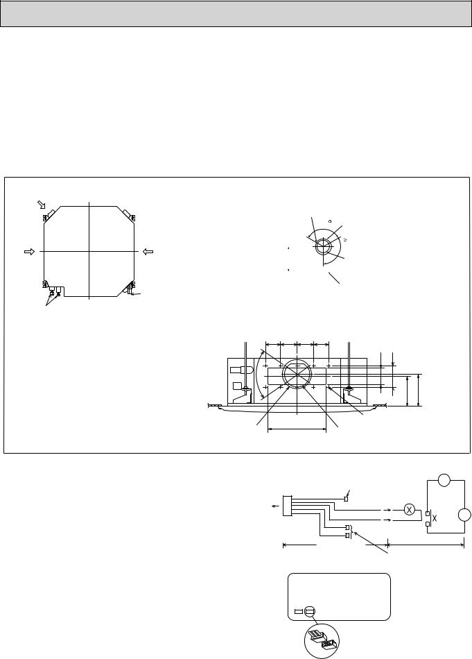
5-2. BRANCH DUCT HOLE AND FRESH AIR INTAKE HOLE
At the time of installation, use the duct holes (cut out) located at the positions shown in following diagram, as and when required.
• A fresh air intake hole for the optional multi function casement can also be made.
Note:
The figures marked with * in the drawing below represent the dimensions of the main unit excluding those of the optional multi function casement.
When installing the optional multi function casement, add 5-5/16” (135 mm) to the dimensions marked on the figure. When installing the branch ducts, be sure to insulate adequately.
Otherwise, condensation and dripping may occur.
Fresh air intake hole
Indoor unit
Refrigerant pipe
|
|
|
|
|
|
|
|
Unit : inch(mm) |
|
Fresh air intake hole diagram |
|||||||
Branch duct hole |
3-:1/8 (:2.8) burring hole |
|
|
|||||
|
120 |
:4-29/32 (:125) burring hole pitch |
||||||
|
|
|
||||||
|
|
|
|
|
|
|
120 |
|
7/32-6 (*158) |
|
|
|
|
|
|||
|
|
|
|
|
|
|||
|
|
|
|
|
|
|
3-:15/16 (:100) cut out hole |
|
|
|
|
|
|
|
|
|
|
|
|
|
|
|
|
|
|
|
Ceiling
Drain pipe
Branch duct hole diagram (view from either side)
3-17/32 3-15/16 |
3-15/16 3-17/32 |
1/8-5(130) |
|
|||
(90) |
(100) |
(90) |
15/16-3 (100) |
|
||
(90) |
|
|
||||
70 |
|
|
|
(155) |
(167) |
|
|
|
|
|
*6-3/32 |
*6-9/16 |
|
|
13-25/32 (350) |
14-:1/8 (:2.8) burring hole |
||||
:6-7/8 (:175) burring hole pitch |
:5-29/32 (:150) cut out hole |
|||||
|
|
|||||
5-3. OPERATION IN CONJUNCTION WITH DUCT FAN (Booster fan)
•Whenever the indoor unit is operating, the duct fan also operates.
(1)Connect the optional multiple remote controller adapter (PAC-SA88HA-E) to the connector CN51 on the indoor controller board.
(2)Drive the relay after connecting the 12V DC relay
between the Yellow and Orange connector lines. MB: Electromagnetic switch power relay for duct fan.
X: Auxiliary relay (For DC 12V, coil rating: 1.0W or smaller)
|
|
|
Be sure to secure insulation |
~ |
|
|
|
|
|
||
CN51 |
5 |
|
material by tape, etc. |
|
|
Green |
|
|
|||
on |
|
|
Yellow |
|
|
indoor |
|
|
|
|
|
controller |
1 |
|
Orange |
|
MB |
board |
Connector (5P) |
Red |
|
|
|
|
Indoor unit side |
Brown |
|
|
|
|
Multiple remote |
Installation at site |
|||
|
|
|
|||
|
|
|
|
|
|
|
|
|
controller adapter |
Be sure to secure insulation |
|
|
|
|
PAC-SA88HA-E |
material by tape, etc. |
|
Indoor controller board
Distance between indoor controller board and relay
must be within 10m (33ft).
CN51
Multiple remote controller adapter PAC-SA88HA-E
CN51
10
5-4. FRESH AIR INTAKE AMOUNT & STATIC PRESSURE CHARACTERISTICS 1 PLFY-P12 · P18 · P24 · P30NBMU-E(R1)
Multifunction casement + High efficiency filter |
Multifunction casement + Standard filter |
10-2)] |
50(20) |
|
|
|
|
|
|
|
|
|
|
|
|
|
|
|
|
|
|
|
|
||
0 |
|
|
|
|
|
|
|
|
|
|
|
[Pa(in.W.G.% |
|
|
|
|
|
|
|
|
|
|
|
-50(-20) |
|
|
|
|
|
|
|
|
2 - inlet |
||
|
|
|
|
|
|
|
|
|
|
|
|
pressure |
-150(-60) |
|
|
|
|
|
|
|
|
|
|
|
|
|
|
|
|
|
|
|
|
||
|
|
|
|
|
|
|
|
|
|
||
|
-100(-40) |
|
|
|
|
|
|
|
|
|
|
Static |
|
|
|
|
|
|
|
|
|
|
|
-200(-80) |
|
|
|
|
|
1 - inlet |
|
|
|
||
|
|
|
|
|
|
|
|
|
|||
|
|
|
|
|
|
|
|
|
|
|
|
|
|
|
|
|
|
|
|
|
|
|
|
|
0 |
1 |
2 |
3 |
4 |
|
5 |
||||
|
|
|
|
50 |
100 |
|
150 |
|
|
||
|
Taking air into the unit Air flow rate |
|
|
|
|
|
|||||
-2)] |
50(20) |
|
|
|
|
|
|
|
|
|
|
|
|
|
|
|
|
|
|
|
|
||
|
|
|
|
|
|
|
|
|
|
|
|
[Pa(in.W.G.%10 |
0 |
|
|
|
|
|
|
|
|
|
|
-50(-20) |
|
|
|
|
|
|
|
|
|
|
|
pressure |
|
|
|
|
|
|
|
|
|
|
|
-150(-60) |
|
|
|
|
|
|
|
|
|
|
|
|
-100(-40) |
|
|
|
|
|
|
|
|
|
|
Static |
-200(-80) |
|
|
|
|
|
|
|
|
|
|
|
0 |
1 |
2 |
3 |
4 |
|
5 |
||||
|
|
|
|
50 |
100 |
|
150 |
|
|
||
|
|
|
|
|
|
|
|||||
Air flow rate
2 PLFY-P36NBMU-E(R1)
Multifunction casement + Standard filter
|
10-2)] |
50(20) |
|
|
|
|
|
|
|
|
|
|
|
|
|
|
|
|
|
|
|
|
|
|
|
|
|
|
|
|
|
|
|
|
|
||
|
|
|
|
|
|
|
|
|
|
|
|
|
|
|
|
|
|
|
|
|
|
|
|
|
|
|
|
|
|
|
|
|
|
|
|
||
|
[Pa(in.W.G.% |
0 |
|
|
|
|
|
|
|
|
|
|
|
|
|
|
|
|
|
|
|
|
|
|
|
|
|
|
|
|
|
|
|
|
|
||
|
-50(-20) |
|
|
|
|
|
|
|
|
|
|
|
|
|
|
|
|
|
|
|
|
|
|
|
|
|
|
|
|
|
|
|
|
|
|||
|
|
|
|
|
|
|
|
|
|
|
2 - inlet |
|
|
|
|
|||
|
|
|
|
|
|
|
|
|
|
|
|
|
|
|
|
|||
|
pressure |
-150(-60) |
|
|
|
|
|
|
|
|
|
|
|
|
|
|
|
|
|
Static |
-100(-40) |
|
|
|
|
|
|
|
|
|
|
|
|
|
|
|
|
|
|
|
|
|
|
|
|
|
|
|
|
|
|
|
|
|
||
|
|
|
|
|
|
|
|
|
|
|
|
|
|
|
|
|
|
|
|
|
|
|
|
|
|
|
|
|
|
|
|
|
|
|
|
|
|
|
|
|
|
|
|
|
|
|
1 - inlet |
|
|
|
|
|
|
|
||
|
-200(-80) |
|
|
|
|
|
|
|
|
|
|
|
|
|
|
|
|
|
|
|
|
|
|
|
|
|
|
|
|
|
|
|
|
6[CMM] |
|||
6[CMM] |
0 |
1 |
2 |
3 |
4 |
5 |
|
|||||||||||
200 |
[CFM] |
|
|
|
|
50 |
|
100 |
150 |
200 |
|
|
[CFM] |
|||||
|
|
|
|
|
|
|||||||||||||
How to read curves
|
Curve in the |
Duct characteristics |
|
1 |
at site |
||
graphs. |
|||
|
|
||
0 |
|
A C |
|
|
|
||
|
Q |
B |
|
|
|
||
2 |
|
|
|
|
|
C A |
|
|
E |
|
|
Q |
|
|
3 |
|
|
D |
|
6[CMM] |
|
200 |
[CFM] |
A |
|
|
Q |
|
|
Qa |
Q…Designed amount of fresh air intake <CMM (CFM)> A…Static pressure loss of fresh air
intake duct system with air flow amount Q <Pa (in.W.G.o10-2)> B…Forced static pressure at air condi-
tioner inlet with air flow amount Q <Pa (in.W.G.o10-2)>
C…Static pressure of booster fan with air flow amount Q <Pa (in.W.G.o10-2)> D…Static pressure loss increase amount of fresh air intake duct system for air flow amount Q <Pa (in.W.G.o10-2)> E…Static pressure of indoor unit with air flow amount Q <Pa (in.W.G.o10-2)> Qa…Estimated amount of fresh air intake without D <CMM (CFM)>
Multifunction casement + High efficiency filter
-2)] |
50(20) |
|
|
|
|
|
|
|
|
|
|
|
|
|
|
|
|
|
|
|
|
|
|
|
|
|
|
|
|
|
|
||
|
|
|
|
|
|
|
|
|
|
|
|
|
|
|
|
|
[Pa(in.W.G.%10 |
0 |
|
|
|
|
|
|
|
|
|
|
|
|
|
|
|
-50(-20) |
|
|
|
|
|
|
|
|
|
|
|
|
|
2 - inlet |
|
|
|
|
|
|
|
|
|
|
|
|
|
|
|
|
|
|
|
pressure |
-150(-60) |
|
|
|
|
|
|
|
|
|
|
|
|
|
|
|
|
|
|
|
|
|
|
|
|
|
|
|
|
|
|
||
|
-100(-40) |
|
|
|
|
|
|
|
|
|
|
|
|
|
|
|
Static |
|
|
|
|
|
|
|
|
|
|
|
|
|
|
|
|
-200(-80) |
|
|
|
|
|
|
|
|
|
|
1 - inlet |
|
|
|
||
|
|
|
|
|
|
|
|
|
|
|
|
|
|
|||
|
|
|
|
|
|
|
|
|
|
|
|
|
|
|
|
|
|
|
|
|
|
|
|
|
|
|
|
|
|
|
|
|
|
|
0 |
2 |
4 |
6 |
8 |
|||||||||||
|
|
|
|
50 |
100 |
150 |
200 |
|
250 |
|
||||||
|
|
|
|
|
||||||||||||
Taking air into the unit |
Air flow rate |
|
|
|
|
|
|
|||||||||
|
|
|
|
|
|
|
|
|||||||||
-2)] |
50(20) |
|
|
|
|
|
|
|
|
|
|
|
|
|
|
|
|
|
|
|
|
|
|
|
|
|
|
|
|||||
|
|
|
|
|
|
|
|
|
|
|
|
|
|
|
|
|
[Pa(in.W.G.%10 |
0 |
|
|
|
|
|
|
|
|
|
|
|
|
|
|
|
-50(-20) |
|
|
|
|
|
|
|
|
|
|
|
|
|
|
|
|
pressure |
|
|
|
|
|
|
|
|
|
|
|
|
|
|
|
|
-150(-60) |
|
|
|
|
|
|
|
|
|
|
|
|
|
|
|
|
|
-100(-40) |
|
|
|
|
|
|
|
|
|
|
|
|
|
|
|
Static |
-200(-80) |
|
|
|
|
|
|
|
|
|
|
|
|
|
|
|
|
0 |
2 |
4 |
6 |
8 |
|||||||||||
|
|
|
|
50 |
100 |
150 |
200 |
|
250 |
|
||||||
|
|
|
|
|
||||||||||||
Air flow rate
Static pressure [Pa(in.W.G.%10-2)]
[CMM]
[CFM]
[CMM]
[CFM]
50(20) |
|
|
|
|
|
|
|
|
|
|
|
|
|
0 |
|
|
|
|
|
|
|
|
|
|
|
|
|
|
|
|
|
|
|
|
|
|
|
|
|
|
|
|
|
|
|
|
|
|
|
|
|
|
|
|
|
-50(-20) |
|
|
|
|
|
|
|
|
|
|
|
|
|
|
|
|
|
|
|
|
|
|
|
|
|
|
|
|
|
|
|
|
|
|
|
|
|
|
|
|
|
-100(-40) |
|
|
|
|
|
|
|
|
|
|
|
|
|
|
|
|
|
|
|
|
|
|
|
|
|
|
|
|
|
|
|
|
|
|
|
|
|
|
|
|
|
|
|
|
|
|
|
|
|
|
|
|
|
|
|
-150(-60) |
|
|
|
|
|
|
|
|
|
2 - inlet |
|
|
|
|
|
|
|
|
|
|
|
|
|
|
|
||
|
|
|
|
|
|
|
|
|
|
|
|
|
|
|
|
|
|
|
|
|
|
|
|
|
|
|
|
|
|
|
|
|
|
|
|
|
|
|
|
|
|
|
|
|
|
|
|
|
|
|
|
|
|
|
|
-200(-80) |
|
|
|
|
1 - inlet |
|
|
|
|
|
|
|
|
|
|
|
|
|
|
|
|
|
|
|
|||
|
|
|
|
|
|
|
|
|
|
|
|
|
|
|
|
|
|
|
|
|
|
|
|
|
|
|
|
0 |
2 |
|
4 |
|
6 |
8 |
[CMM] |
||||||
|
50 |
100 |
150 |
200 |
|
250 |
|
|
[CFM] |
||||
|
|
|
|
||||||||||
Air flow rate
11
 Loading...