


Mitsubishi PLA-RP_AA(1), PLA-RP_AA(1).UK, PEA-RP_EA, PEAD-RP_EA, PEAD-RP_EA.UK TECHNICAL MANUAL
...SPLIT-TYPE, HEAT PUMP AIR CONDITIONERS
No. OCT04
SERVICE TECHNICAL GUIDE R410A
<Indoor unit> |
[Service Ref] |
[Model names] |
PLA-RP·AA
PEA-RP·EA
PEAD-RP·EA
PLA-RP·AA
PLA-RP·AA1 PLA-RP·AA.UK PLA-RP·AA1.UK PEA-RP·EA.TH-A PEAD-RP·EA.UK PEAD-RP·EA1.UK
<Outdoor unit> |
[Service Ref] |
[Model names] |
PUHZ-RP·VHA
PUHZ-RP·VHA PUHZ-RP·VHA-A
CONTENTS
1.PAIRING TABLE OF THE INDOOR AND OUTDOOR UNIT ·····2
2.SPECIFICATIONS FOR ELECTRICAL WORK ···········
3.WIRING DIAGRAM·······················
4.REFRIGERANT SYSTEM DIAGRAM ···············
5.HOW TO CHECK THE PARTS ··················
6.MICROPROCESSOR CONTROL·················
7.INDOOR UNIT CONTROL····················
8.OUTDOOR UNIT CONTROL···················
9.DIP SWITCH FUNCTION ·····················
10.FUNCTION SETTING ······················
11.TEST RUN • REPLACEMENT OPERATION
&EMERGENCY OPERATION···················
12.SELF-DIAGNOSIS ························
13.TEST POINT DIAGRAM ·····················
14.TROUBLESHOOTING ······················
15.SYSTEM CONTROL·······················
1 PAIRING TABLE OF THE INDOOR AND OUTDOOR UNITS
Outdoor unit [PUHZ]
Indoor unit |
OC294 |
RP3VHA RP4VHA RP5VHA RP6VHA
PLA-RP·AA |
OC293 |
PLA-RP·AA1 |
REVISED EDITION-A |
PLA-RP·AA.UK OC297
PLA-RP·AA1.UK REVISED EDITION-A
PEAD-RP·EA.UK
—
PEAD-RP·EA1.UK
|
|
Outdoor unit [PUHZ] |
Indoor unit |
OC300 REVISED EDITION-A |
|
|
|
RP3VHA-A RP4VHA-A RP5VHA-A RP6VHA-A |
PEA–RP·EA.TH-A |
OC299 |
|
REVISED EDITION-A |
|
|
2
2 SPECIFICATIONS FOR ELECTRICAL WORK
2-1. Field electrical wiring(power wiring specifications) PUHZ-RP•VHA
PUHZ-RP•VHA-A
Models (Outdoor unit) Indoor unit power supply
Outdoor unit |
Phase |
|
Power supply |
Frequency & Voltage |
|
Input capacity |
Indoor unit(A) |
|
Main switch/Fuse |
Outdoor unit(A) |
|
Outdoor unit |
Wire No. |
|
Power supply |
||
|
||
Wiring Wire No. o size (e) |
||
Indoor unit/Outdoor unit connecting
Remote controller-indoor unit connecting Wire No. o size (e)
Control circuit rating
RP3V |
RP4V |
RP5V |
RP6V |
|
~ / N (Single), 50Hz, 220-230-240V |
|
|
|
|
~ / N (Single) |
|
|
|
50Hz, 220-230-240V |
|
— |
— |
— |
— |
25/25 |
32/32 |
32/32 |
40/40 |
3 |
3 |
3 |
3 |
3 o 2.5 cable (Polar)
Cable 2C o 0.69
This wire is accessory of remote controller (Wire length: 10m, Non-polar) Indoor unit-Outdoor unit: S1-S2 AC220V-230V-240V
S2-S3 DC24V
Remote controller-Indoor unit: DC14V
Check items
1.Wiring size must comply with the applicable local and national code.
2.Be careful about choosing the installation location for the earth leakage breaker and how it is installed as the initial electric current may cause it to malfunction.
3.Power supply cords and indoor unit / Outdoor unit connecting cords shall not be lighter than polychloroprene sheathed flexible cord. (design 254 IEC 57)
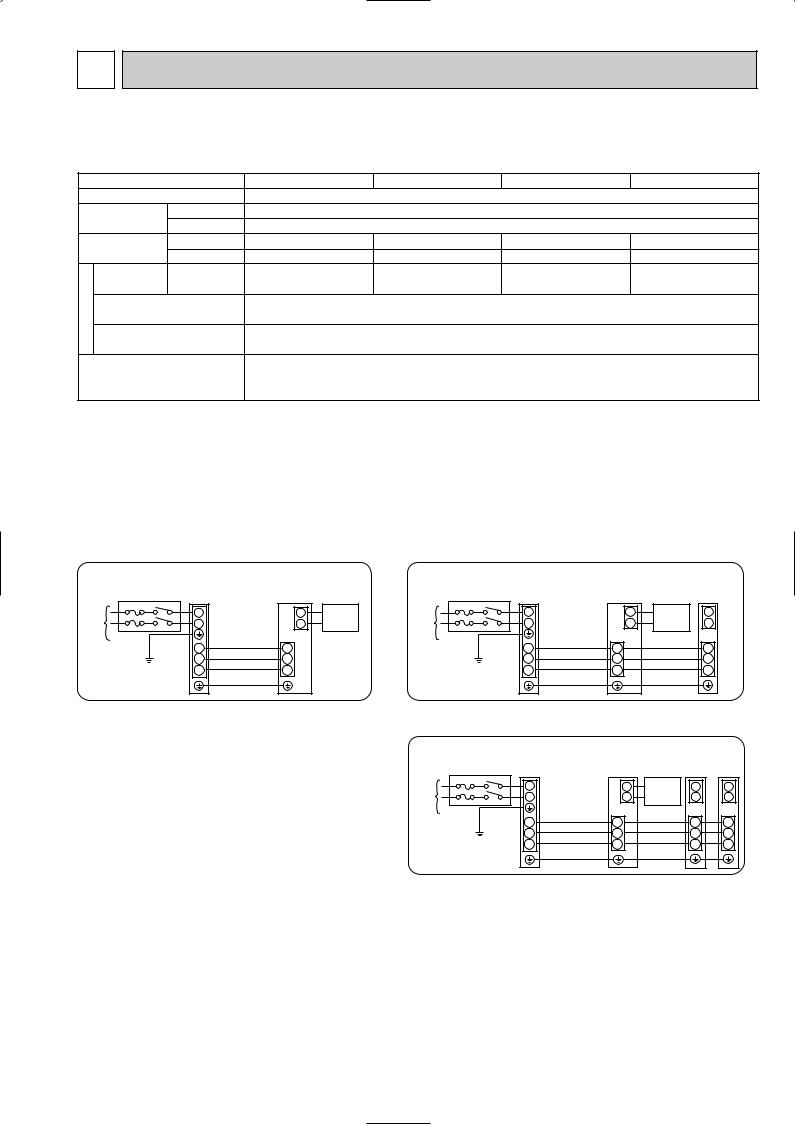
1:1 system |
|
|
|
|
Synchronized twin and triple system |
Electrical wiring |
|||||
|
|
|
|
|
• Synchronized twin |
|
|
|
|
|
|
|
Outdoor |
Indoor |
|
|
Outdoor |
Indoor |
|
Indoor |
|||
|
unit |
|
unit |
|
|
unit |
|
unit |
|
unit |
|
Unit |
L |
|
1 |
Remote |
Unit |
L |
|
1 |
Remote |
|
1 |
power |
N |
|
2 |
controller |
power |
N |
|
2 |
controller |
2 |
|
supply |
|
Indoor/outdoor |
|
|
supply |
|
Indoor/outdoor |
|
|
|
|
|
|
unit connection |
|
|
|
|
unit connection |
|
|
|
|
|
S1 |
cable |
S1 |
|
|
S1 |
cable |
S1 |
|
|
S1 |
|
|
|
|
|
|
|
|||||
|
S2 |
|
S2 |
|
|
S2 |
|
S2 |
|
|
S2 |
Grounding |
S3 |
|
S3 |
|
Grounding |
S3 |
|
S3 |
|
|
S3 |
|
|
|
|
|
• Synchronized triple |
|
|
|
|
|
|
|
|
|
|
|
|
Outdoor |
Indoor |
|
Indoor Indoor |
||
|
|
|
|
|
|
unit |
|
unit |
|
unit |
unit |
|
|
|
|
|
Unit |
L |
|
1 |
Remote |
1 |
1 |
|
|
|
|
|
power |
N |
|
2 |
controller |
2 |
2 |
|
|
|
|
|
supply |
|
Indoor/outdoor |
|
|
|
|
|
|
|
|
|
|
|
|
|
|
|
|
|
|
|
|
|
|
S1 |
connection cable |
S1 |
|
S1 |
S1 |
|
|
|
|
|
|
|
|
||||
|
|
|
|
|
|
S2 |
|
S2 |
|
S2 |
S2 |
|
|
|
|
|
Grounding |
S3 |
|
S3 |
|
S3 |
S3 |
3

2-2. M-NET wiring method
(Points to notice)
(1)Outside the unit, transmission wires should stay away from electric wires in order to prevent electromagnetic noise from making an influence on the signal communication. Place them at intervals of more than 5cm. Do not put them in the same conduit tube.
(2)Terminal block (TB7) for transmission wires should never be connected to 220~240V power supply. If it is connected, electronic parts on M-NET p.c. board may be burn out.
(3)Use 2-core x 1.25mm2 shield wire (CVVS, CPEVS) for the transmission wire. Transmission signals may not be sent or received normally if different types of transmission wires are put together in the same multi-conductor cable. Never do this because this may cause a malfunction.
Group |
|
Refrigerant |
Refrigerant |
Refrigerant |
|
address 00 |
address 00 |
address 00 |
|
remote |
|
|||
controller |
|
M-NET |
M-NET |
M-NET |
|
Power |
address 01 |
address 02 |
address 03 |
|
supply |
|
|
|
|
unit for |
|
|
|
|
transmission |
|
|
|
|
wire |
|
|
|
A-control |
A-control |
A-control |
remote |
remote |
remote |
controller |
controller |
controller |
It would be ok if M-NET wire (non-polar, 2-cores) is arranged in addition to the wiring for A-control.
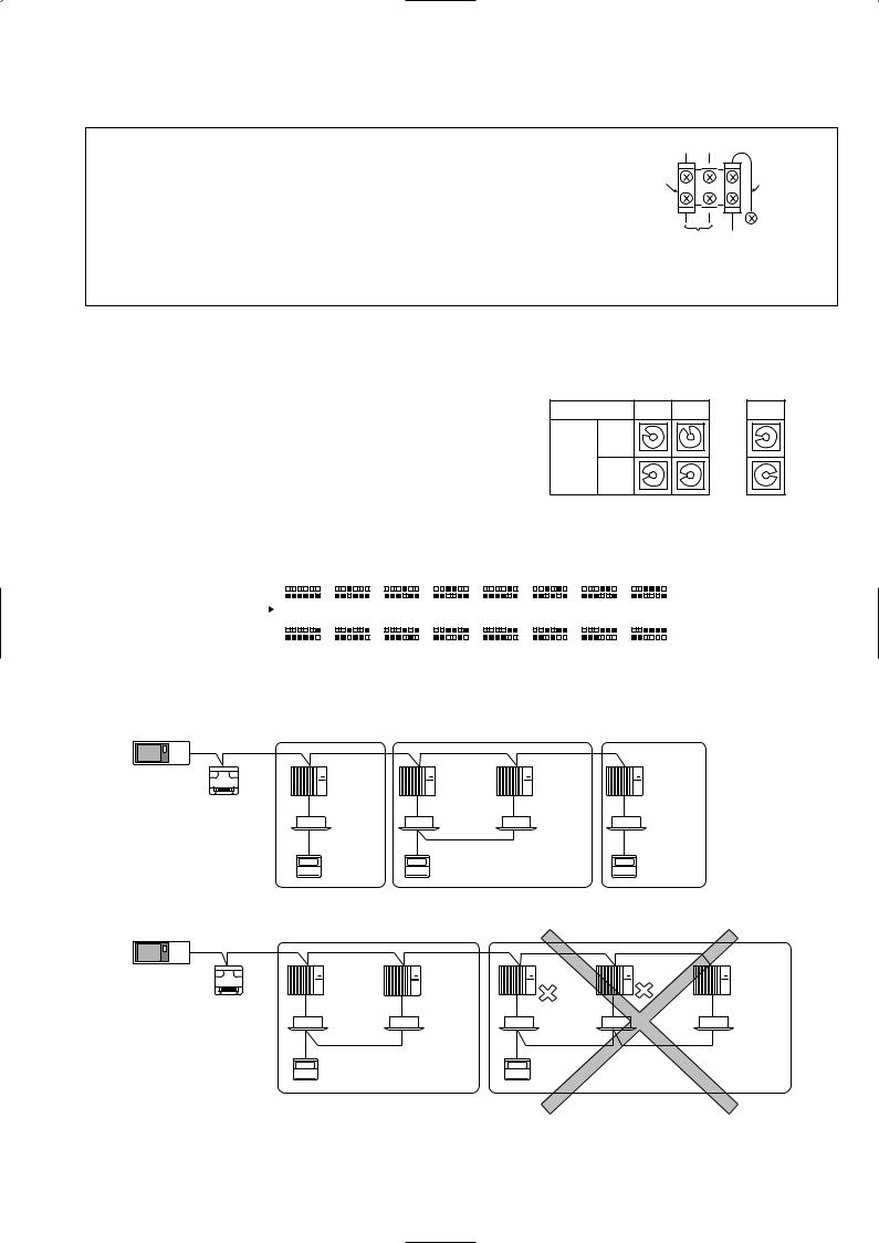
(4)Ground only one of any appliances through M-NET transmission wire (shield wire). Communication error may occur due to the influence of electromagnetic noise.
“Ed” error will appear on the LED display of outdoor unit. “0403” error will appear on the central-control remote controller.
Bad example (Multi spot grounding of shield wire)
Central |
|
Power |
|
M-NET type |
|
M-NET type |
|
M-NET type |
remote |
|
supply |
|
|
|
|||
|
|
outdoor unit |
|
outdoor unit |
|
outdoor unit |
||
controller |
|
appliance |
|
|
|
|||
|
|
|
|
|
|
|
M-NET transmission wire
Good example 1 (Single spot grounding of shield wire) |
|
||||
Central |
Power |
M-NET type |
M-NET type |
M-NET type |
|
remote |
supply |
||||
outdoor unit |
outdoor unit |
outdoor unit |
|||
controller |
appliance |
||||
|
|
|
|||
M-NET transmission wire |
|
|
|
||
Good example 2 (Single spot grounding of shield wire) |
|
||||
Central |
Power |
M-NET type |
M-NET type |
M-NET type |
|
remote |
supply |
||||
outdoor unit |
outdoor unit |
outdoor unit |
|||
controller |
appliance |
||||
|
|
|
|||
M-NET transmission wire |
|
|
|
||
If there are more than two grounding spots on the shield wire, noise may enter into the shield wire because the ground wire and shield wire form one circuit and the electric potential difference occurs due to the impedance difference among grounding spots. In case of single spot grounding, noise does not enter into the shield wire because the ground wire and shield wire do not form one circuit.
To avoid communication errors caused by noise, make sure to observe the single spot grounding method described in the installation manual.
4
|
|
|
|
|
|
● M-NET wiring |
|
|
|
||
(1) |
Use 2-core x 1.25mm2 shield wire for electric wires. |
M-NET |
|
|
|
|
|
||||
|
(Excluding the case connecting to system controller.) |
terminal |
|
Ground |
|
|
block |
|
|||
(2) |
Connect the wire to the M-NET terminal block.Connect one core of the |
|
wire |
||
|
|
||||
|
|
|
|||
|
transmission wire (non-polar) to A terminal and the other to B. Peel the |
|
|
|
|
|
A B |
S |
|||
|
shield wire, twist the shield part to a string and connect it to S terminal. |
||||
|
Transmission |
Shield |
|||
(3) |
In the system which several outdoor units are being connected, the terminal |
||||
wire |
part |
||||
|
|
||||
(A, B, S) on M-NET terminal block should be individually wired to the other
outdoor unit’s terminal, i.e. A to A, B to B and S to S.In this case, choose one of those outdoor units and drive a screw to fix an ground wire on the plate as shown on the right figure.
2-2-1. M-NET address setting
In A-control models, M-NET address and refrigerant address should be set only for the outdoor unit. Similar to Free Combo system, there is no need to set the address of outdoor unit and remote controller. To construct a central control system, the setting of M-NET address should be conducted only upon the outdoor unit. The setting range should be 1 to 50 (the same as that of the indoor unit in Free Combo system), and the address number should be consecutively set in a same group.
Address number can be set by using rotary switches (SW11 for ones digit and SW12 for tens digit), which is located on the M-NET p.c. board of outdoor unit.
(Factory setting: all addresses are set to “0”.)
2-2-2. Refrigerant address setting
<Setting example> M-NET Address No.
SW11
ones
Switng digit setting SW12
tens digit
1
2 |
34 |
|
01 |
5 |
|
9 |
7 |
6 |
8 |
|
|
2 |
34 |
|
01 |
5 |
|
9 |
7 |
6 |
8 |
|
|
2 |
|
50 |
|||
2 |
34 |
2 |
34 |
||
01 |
5 |
01 |
5 |
||
9 |
7 |
6 |
9 |
7 |
6 |
8 |
|
8 |
|
||
2 |
34 |
~ |
34 |
||
2 |
|||||
01 |
5 |
01 |
5 |
||
9 |
7 |
6 |
9 |
7 |
6 |
8 |
|
8 |
|
||
In case of multiple grouping system (multiple refrigerant circuits in one group), indoor units should be connected by remote controller wiring (TB5) and the refrigerant address needs to be set. Leave the refrigerant addresses to “00” if the group setting is not conducted. Set the refrigerant address by using DIP SW1-3 to -6 on the outdoor controller board. [Factory setting: all switches are OFF. (All refrigerant addresses are “00”.)]
|
|
|
ON |
|
|
|
|
|
|
|
ON |
|
|
|
|
|
|
|
ON |
|
|
|
|
|
|
|
ON |
|
|
|
|
|
|
|
ON |
|
|
|
|
|
|
|
ON |
|
|
|
|
|
|
|
ON |
|
|
|
|
|
|
|
ON |
|
|
|
|
|
|
|
|
|
|
|
|
|
|
|
|
|
|
|
|
|
|
|
|
|
|
|
|
|
|
|
|
|
|
|
|
|
|
|
|
|
|
|
|
|
|
|
|
|
|
|
|
|
|
|
|
|
|
|
|
|
|
|
|
|
|
||||||||
|
|
|
OFF |
|
|
|
|
|
|
|
OFF |
|
|
|
|
|
|
|
OFF |
|
|
|
|
|
|
|
OFF |
|
|
|
|
|
|
|
OFF |
|
|
|
|
|
|
|
OFF |
|
|
|
|
|
|
|
OFF |
|
|
|
|
|
|
|
OFF |
|
|
|
|
|
|
|
|
|
|
|
|
|
|
|
|
|
|
|
|
|
|
|
|
|
|
|
|
|
|
|
|
|
|
|
|
|
|
|
|
|
|
|
|
|
|
|
|
|
|
|
|
|
|
|
|
|
|
|
|
|
|
|
|
|
|
|
|
|
|
|
|
|
|
Refuigrant |
|
|
|
1 |
2 |
3 |
4 |
5 |
6 |
|
1 |
2 |
3 |
4 |
5 |
6 |
1 |
2 |
3 |
4 |
5 |
6 |
|
1 |
2 |
3 |
4 |
5 |
6 |
|
1 |
2 |
3 |
4 |
5 |
6 |
|
1 |
2 |
3 |
4 |
5 |
6 |
|
1 |
2 |
3 |
4 |
5 |
6 |
|
1 |
2 |
3 |
4 |
5 |
6 |
|||||||||
|
|
|
|
|
0 |
|
|
|
|
|
|
|
1 |
|
|
|
|
|
|
|
2 |
|
|
|
|
|
|
|
3 |
|
|
|
|
|
|
|
4 |
|
|
|
|
|
|
|
5 |
|
|
|
|
|
|
|
6 |
|
|
|
|
|
|
|
7 |
|
|
|
|
|
|
|
|
|
|
|
|
|
|
|
|
|
|
|
|
|
|
|
|
|
|
|
|
|
|
|
|
|
|
|
|
|
|
|
|
|
|
|
|
|
|
|
|
|
|
|
|
|
|
|
|
|
|
|
|
|
|
||||||||||
address |
|
|
|
|
|
|
|
|
|
|
|
|
|
|
|
|
|
|
|
|
|
|
|
|
|
|
|
|
|
|
|
|
|
|
|
|
|
|
|
|
|
|
|
|
|
|
|
|
|
|
|
|
|
|
|
|
|
|
|
|
|
|
|
|
||
|
|
|
ON |
|
|
|
|
|
|
|
ON |
|
|
|
|
|
|
|
ON |
|
|
|
|
|
|
|
ON |
|
|
|
|
|
|
|
ON |
|
|
|
|
|
|
|
ON |
|
|
|
|
|
|
|
ON |
|
|
|
|
|
|
|
ON |
|
|
|
|
|
|
|
|
|
|
OFF |
|
|
|
|
|
|
|
OFF |
|
|
|
|
|
|
|
OFF |
|
|
|
|
|
|
|
OFF |
|
|
|
|
|
|
|
OFF |
|
|
|
|
|
|
|
OFF |
|
|
|
|
|
|
|
OFF |
|
|
|
|
|
|
|
OFF |
|
|
|
|
|
|
|
|
|
|
|
|
|
|
|
|
|
|
|
|
|
|
|
|
|
|
|
|
|
|
|
|
|
|
|
|
|
|
|
|
|
|
|
|
|
|
|
|
|
|
|
|
|
|
|
|
|
|
|
|
|
|
|
|
|
|
|
|
|
|
|
|
|
|
|
|
|
|
1 |
2 |
3 |
4 |
5 |
6 |
|
|
1 |
2 |
3 |
4 |
5 |
6 |
|
1 |
2 |
3 |
4 |
5 |
6 |
|
|
1 |
2 |
3 |
4 |
5 |
6 |
|
|
1 |
2 |
3 |
4 |
5 |
6 |
|
|
1 |
2 |
3 |
4 |
5 |
6 |
|
|
1 |
2 |
3 |
4 |
5 |
6 |
|
|
1 |
2 |
3 |
4 |
5 |
6 |
|
|
|
|
|
|
|
|
8 |
|
|
|
|
|
|
|
9 |
|
|
|
|
|
|
|
10 |
|
|
|
|
|
|
11 |
|
|
|
|
|
|
12 |
|
|
|
|
|
|
13 |
|
|
|
|
|
|
14 |
|
|
|
|
|
|
15 |
|
|
|
||||||
2-2-3. Regulations in address settings
In case of multiple grouping system, M-NET and refrigerant address settings should be done as explained in the above section. Set the lowest number in the group for the outdoor unit whose refrigerant address is “00” as its M-NET address.
|
|
Group A |
Group B |
|
Group C |
System |
|
Refrigerant |
Refrigerant |
Refrigerant |
Refrigerant |
|
address 00 |
address 00 |
address 01 |
address 00 |
|
controller |
|
||||
|
M-NET |
M-NET |
M-NET |
M-NET |
|
|
|
||||
|
Power |
address 01 |
address 02 |
address 03 |
address 04 |
|
|
|
|
|
|
|
supply |
|
|
|
|
|
unit for |
|
|
|
|
|
transmission |
|
|
TB5 |
|
|
wire |
|
|
|
|
|
|
A-control |
A-control |
|
A-control |
|
|
remote |
remote |
|
remote |
|
|
controller |
controller |
|
controller |
w Refrigerant addresses can be overlapped if they are in the different group.
|
Group A |
|
|
Group B |
|
|
System |
Refrigerant |
Refrigerant |
Refrigerant |
Refrigerant |
Refrigerant |
|
address 00 |
address 01 |
address 00 |
address 01 |
address 02 |
||
controller |
||||||
M-NET |
M-NET |
M-NET |
M-NET |
M-NET |
||
|
||||||
Power |
address 01 |
address 02 |
address 04 |
address 03 |
address 05 |
|
supply |
|
|
|
|
|
|
unit for |
|
|
|
|
|
|
transmission |
|
|
TB5 |
|
|
|
wire |
|
|
|
|
||
|
A-control |
|
A-control |
|
|
|
|
remote |
|
remote |
|
|
|
|
controller |
|
controller |
|
|
wIn group B, M-NET address of the outdoor unit whose refrigerant address is “00” is not set to the minimum in the group. As “3” is right for this situation, the setting is wrong. Taking group A as a good sample, set the minimum M-NET address in the group for the outdoor unit whose refrigerant address is “00”.
5
3 
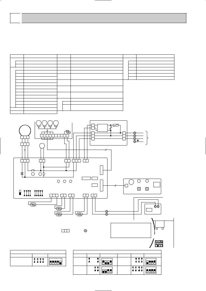
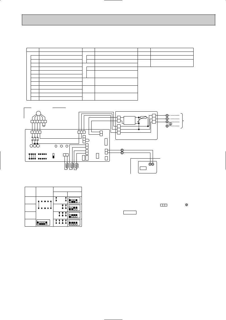
 WIRING DIAGRAM
PLA-RP3AA
PLA-RP3AA1 PLA-RP3AA.UK PLA-RP3AA1.UK
[LEGEND]
PLA-RP4AA
PLA-RP4AA1 PLA-RP4AA.UK PLA-RP4AA1.UK
PLA-RP5AA
PLA-RP5AA1 PLA-RP5AA.UK PLA-RP5AA1.UK
PLA-RP6AA
PLA-RP6AA1 PLA-RP6AA.UK PLA-RP6AA1.UK
SYMBOL |
|
NAME |
|
|
SYMBOL |
NAME |
|
SYMBOL |
|
NAME |
||
P.B |
INDOOR POWER BOARD |
MV |
|
VANE MOTOR |
|
W.B |
WIRELESS REMOTE CONTROLLER BOARD |
|||||
F1 |
FUSE (4A) |
|
|
|
DP |
|
DRAIN-UP MACHINE |
|
|
RU |
RECEIVING UNIT |
|
ZNR |
VARISTOR |
|
|
DS |
|
DRAIN SENSOR |
|
|
BZ |
BUZZER |
|
|
I.B |
INDOOR CONTROLLER BOARD |
H2 |
|
DEW PREVENTION HEATER |
|
|
LED1 |
LED (RUN INDICATOR) |
||||
CN2L |
CONNECTOR (LOSSNAY) |
TB4 |
|
TERMINAL BLOCK (INDOOR/OUTDOOR CONNECTING LINE) |
|
LED2 |
LED (HOT ADJUST) |
|||||
CN32 |
CONNECTOR (REMOTE SWITCH) TB5 |
|
TERMINAL BLOCK (REMOTE CONTROLLER |
|
SW1 |
SWITCH (HEATING ON/OFF) |
||||||
CN41 |
CONNECTOR (HA TERMINAL-A) |
|
|
TRANSMISSION LINE) |
|
|
SW2 |
SWITCH (COOLING ON/OFF) |
||||
SW1 |
JUMPER WIRE (MODEL SELECTION) TH1 |
|
ROOM TEMPERATURE THERMISTOR |
|
|
|
|
|||||
SW2 |
JUMPER WIRE (CAPACITY CORD) |
|
|
(0:/15kΩ , 25:/5.4kΩ DETECT) |
|
|
|
|
|
|||
SWE |
SWITCH (EMERGENCY OPERATION) TH2 |
|
PIPE TEMPERATURE THERMISTOR/LIQUID |
|
|
|
|
|||||
X1 |
RELAY (DRAIN PUMP) |
|
|
|
(0:/15kΩ , 25:/5.4kΩ DETECT) |
|
|
|
|
|
||
X4 |
RELAY (FAN MOTOR) |
|
TH5 |
|
COND./EVA. TEMPERATURE THERMISTOR |
|
|
|
|
|||
FC |
FAN PHASE CONTROL |
|
|
(0:/15kΩ , 25:/5.4kΩ DETECT) |
|
|
|
|
|
|||
LED1 |
POWER SUPPLY (I.B) |
|
R.B |
|
REMOTE CONTROLLER BOARD |
|
|
|
|
|
||
LED2 |
POWER SUPPLY (I.B) |
|
|
CN2 |
CONNECTOR (PROGRAM TIMER) |
|
|
|
|
|
||
LED3 |
TRANSMISSION (INDOOR-OUTDOOR) |
|
TB6 |
TERMINAL BLOCK (REMOTE CONTROLLER |
|
|
|
|
||||
C |
CAPACITOR (FAN MOTOR) |
|
|
TRANSMISSION LINE) |
|
|
|
|
|
|||
MF |
FAN MOTOR |
|
|
|
|
|
|
|
|
|
|
|
|
|
|
GRILLE |
|
|
|
|
|
P.B |
|
|
|
|
|
MV MV MV MV |
|
CN2S(WHT) |
F1 |
|
|
|
||||
|
|
|
|
|
|
|
||||||
|
|
|
2 |
|
|
|
|
|||||
|
|
5 |
5 |
5 |
|
|
|
|
|
|
|
|
MF |
5 |
H2 |
1 DC14V |
ZNR |
|
TB4 |
|
|||||
|
5 |
|
|
|
|
|||||||
|
|
|
|
3 |
|
1 |
YLW |
S1 |
|
|||
|
|
1 2 3 6 |
7 4 |
8 9 5 10 |
|
ORN |
S2 |
|
||||
1 2 3 |
2 |
|
2 |
|
||||||||
|
BRN |
S3 |
TO OUTDOOR UNIT |
|||||||||
|
|
|
|
|
1 |
|
3 |
|||||
|
|
|
|
|
|
|
|
|
|
|||
|
1 |
2 |
3 |
|
C |
|
|
I.B |
RED |
WHT |
BLK |
FAN 1 3 5 (WHT)
FC
SWE |
SW2 |
ON |
J24 J23 J22 J21 |
OFF |
|
|
|
|
|
|
|
|
|
|
|
|
|
|
|
|
CONTROLLER BOARD OUTDOOR UNIT |
|
|
|||
|
|
|
|
|
DP |
|
|
|
|
|
|
|
|
|
|
CN02 (WHT) |
CN01 (BLU) |
|
|
||
|
|
|
|
|
|
|
|
|
|
|
|
|
|
|
|
|
5 |
|
|
|
|
|
|
|
|
|
|
|
|
|
|
|
|
|
|
|
|
|
|
|
|
|
|
|
|
|
YLW |
YLW |
|
|
|
|
YLW YLW |
|
YLW ORN |
BRN |
BLK |
WHT |
POWER VANE |
|
|
|
|||
D.U.M |
1 3 |
D.HEATER |
1 3 |
1 3 5 |
1 2 |
|
|
|
|||||||||||||
CNP |
|
CNC (RED) |
CN2D |
CN6V |
|
|
|
||||||||||||||
(BLU) |
|
|
|
|
|
|
|
|
|
|
POWER |
(WHT) |
(WHT) |
|
|
|
|||||
X4 |
|
|
|
|
|
|
|
|
|
|
|
|
CN03 |
|
|
|
|
|
|
|
|
|
|
|
|
|
|
|
|
|
|
|
|
(RED) |
|
|
|
|
|
|
|
||
|
|
|
|
|
|
|
|
|
|
|
|
|
|
|
|
|
|
|
|
||
X4 |
|
|
|
X1 |
X1 |
|
|
|
|
|
|
|
CN41 CN2L |
W.B |
|
|
|||||
|
|
|
|
|
|
|
|
|
|
|
|
|
|
|
|
||||||
|
|
|
|
|
|
|
|
|
|
|
|
|
|
|
|
|
|
|
|
|
|
|
|
|
|
|
|
|
|
LED3 LED2 LED1 |
|
|
|
CN32 |
9 |
BZ |
LED1 |
||||||
|
|
|
|
|
|
|
|
|
|
|
|
|
|
LED2 |
|||||||
|
|
|
|
|
|
|
|
|
|
|
|
|
|
|
|||||||
|
SW1 |
D.SENSOR INTAKE LIQUID |
|
PIPE |
REMOCON |
CNB |
|
RU |
|||||||||||||
|
|
|
|
|
|
CN31 |
|
CN20 |
CN21 |
|
CN29 |
CN22 |
|
|
|||||||
|
|
|
|
|
|
|
|
|
|
SW1 |
SW2 |
||||||||||
J11 |
J12 |
J13 |
|
J14 |
J15 |
(WHT) |
(RED) |
(WHT) |
|
(BLK) |
(BLU) |
WIRELESS |
|
||||||||
|
1 |
2 |
3 |
1 |
2 |
1 |
2 |
|
1 |
2 |
1 |
2 |
CN90 |
|
|
|
|||||
|
|
|
|
|
|
|
|
|
|
||||||||||||
|
|
|
|
|
|
|
|
|
|
|
|
|
|
|
|
|
|
(WHT) |
|
|
|
|
BLK |
BLK |
BLK |
BLK |
BLK |
BLK |
BLU BLU |
|
|
DS |
TH1 |
|
|
TH5 |
|
|
2TB5 |
CN2 |
|
|
TH2 |
|
|
|
|
|
|||
NOTES: |
|
|
|
|
|
1 |
|
|
|
|
|
|
|
|
|
|
TRANSMISSION |
||
1.Since the outdoor side electric wiring may change be sure to |
|
|
|
WIRES DC12V |
|||||
check the outdoor unit electric wiring for servicing. |
|
|
|
|
|
|
|||
2.Indoor and outdoor connecting wires are made with polarities, make |
|
|
Please set the voltage using |
||||||
wiring matching terminal numbers (S1,S2,S3). |
|
|
|
|
|
|
the remote controller. |
||
3.Symbols used in wiring diagram above are, |
|
:Connector, |
:Terminal (block). |
|
For the setting method, please |
||||
|
|
|
|
|
|
|
|
|
refer to the indoor unit Installation |
[Servicing] |
|
|
|
|
|
|
|
|
Manual. |
Fasten terminal of the terminal board "TB4" equips lock system.
To remove the fastened terminal, pull it while pressing the protruding portion (locking lever) of the terminal. The fastened terminal protruding portion should face upward.
R.B
1 2 TB6
C
 TB4
TB4
|
SW1 |
|
MODELS |
Manufacture Service board |
|
PLA-RP3,4,5,6AA |
|
1 2 3 4 5 |
PLA-RP3,4,5,6AA1 |
|
ON |
J11J12J13J14J15 |
OFF |
|
|
|
|
MODELS
PLA-RP3AA PLA-RP3AA1
PLA-RP4AA PLA-RP4AA1
|
|
|
SW2 |
|
|
|
|
|
|
Manufacture Service board |
MODELS |
Manufacture |
Service board |
||||||
1 |
2 |
3 |
4 |
PLA-RP5AA |
|
1 |
2 |
3 |
4 |
|
|
|
ON |
|
|
|
|
ON |
|
J21J22J23J24 |
|
|
OFF |
|
J21J22J23J24 |
|
|
|
OFF |
1 |
2 |
3 |
4 |
PLA-RP5AA1 |
|
1 |
2 |
3 |
4 |
|
|
|
ON |
PLA-RP6AA |
|
|
|
|
ON |
J21J22J23 J24 |
|
|
OFF |
PLA-RP6AA1 |
J21J22J23 J24 |
|
|
|
OFF |
6
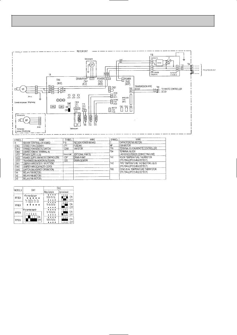
PEA-RP3EA.TH-A PEA-RP5EA.TH-A
PEA-RP4EA.TH-A PEA-RP6EA.TH-A
SYMBOL |
NAME |
SYMBOL |
NAME |
SYMBOL |
NAME |
I.B |
INDOOR CONTROLLER BOARD |
P.B |
INDOOR POWER BOARD |
C |
CAPACITOR(FAN MOTOR) |
CN2L |
CONNECTOR(LOSSNAY) |
F1 |
FUSE(4A) |
MF |
FAN MOTOR |
CN32 |
CONNECTOR(REMOTE SWITCH)) |
ZNR |
VARISTOR |
TB4 |
TERMINAL BLOCK |
CN41 |
CONNECTOR(HA TERMINAL-A) |
R.B |
REMOTE CONTROLLER BOARD |
|
(INDOOR/OUTDOOR CONNECTING LINE) |
LED1 |
POWER SUPPLY(I.B) |
CN2 |
CONNECTOR(PROGRAM TIMER) |
|
|
LED2 |
POWER SUPPLY(R.B) |
TB6 |
TERMINAL BLOCK(REMOTE |
|
|
LED3 |
TRANSMISSOION(INDOOR • OUTDOOR) |
|
CONTROLLER TRANSMISSON LINE) |
|
|
SW1 |
JUMPER WIRE(MODEL SELECTION) |
TH1 |
ROOM TEMPERATURE THERMISTOR |
|
|
SW2 |
JUMPER WIRE(CAPACITY CORD) |
|
(0˚C/15kΩ , 25˚C/5.4kΩ DETECT) |
|
|
SWE |
SWITCH(EMERGENCY OPERATION) |
TH2 |
PIPE TEMPERATURE THERMISTOR/LIQUID |
|
|
X4 |
RELAY(FAN MOTOR) |
|
(0˚C/15kΩ , 25˚C/5.4kΩ DETECT) |
|
|
X5 |
RELAY(FAN MOTOR) |
TH5 |
COND./EVA. TEMPERATURE THERMISTOR |
|
|
X6 |
RELAY(FAN MOTOR) |
|
(0˚C/15kΩ , 25˚C/5.4kΩ DETECT) |
|
|
INDOOR UNIT
|
|
MF |
|
|
|
|
|
|
|
|
|
|
|
2 |
3 |
4 |
1 |
|
5 |
6 |
|
|
|
|
|
|
|
BLK |
BLU |
BRN |
WHT |
RED |
C |
ORN |
|
YLW |
ORN |
BRN |
WHT |
BLK |
|
I.B |
|
|
|
|
|
|
|
|
|
|
|
|
|
FAN 1 |
3 |
5 |
7 |
|
|
|
|
POWER |
1 3 |
5 |
|
|
1 POWER |
(WHT) |
|
|
|
|
|
|
|
CN03 |
|
|
|
|
2 CN2D |
|
|
|
|
|
|
|
|
(RED) |
|
3 |
CN31 |
(WHT) |
|
|
|
|
|
|
|
|
|
|
|
|
|||
|
|
|
|
|
|
|
|
|
|
2 |
|
WIRELESS |
|
X6 X5 X4 |
|
|
|
|
|
|
1 |
|
|
CN90 |
|||
|
|
|
|
|
|
|
|
|
|
|
2 |
LIQUID |
(WHT) |
X6 X5 X4 |
|
|
|
|
|
|
|
|
|||||
|
|
|
|
|
|
|
1 |
CN21 |
REMOCON |
||||
|
|
|
|
|
|
|
LED3 LED2 LED1 |
|
|
(WHT) |
|||
|
|
|
|
|
|
|
|
|
2 INTAKE |
CN22 |
|||
SW2 |
|
|
SW1 |
|
SWE |
PIPE |
|
|
(BLU) 2 |
||||
|
|
|
|
|
1 |
CN20 |
1 |
||||||
J24 J23 J22 J21 |
J15 J14 J13 J12 J11 |
ON |
CN29 2 1 |
|
|
|
(RED) |
|
|||||
OFF |
(BLK) |
|
|
|
CN41 |
CN2L |
|||||||
|
|
|
|
|
|
|
|
CN24 |
|
|
|||
|
|
|
|
|
|
|
|
|
|
|
|
CN32 |
|
TH5 TH2 TH1
CN2S(WHT) |
|
|
|
TB4 |
|
||
F1 |
1 |
YLW |
S1 |
|
|||
|
|
|
|||||
2 |
|
|
ORN |
S2 |
|
||
DC14V |
|
2 |
TO OUTDOOR UNIT |
||||
1 |
ZNR |
BRN |
S3 |
||||
3 |
|||||||
|
|
|
|
|
|
||
3
2
1
CONT.BOARD OUTDOOR CN02(WHT) CN01(BLU)
P.B
TB5
BLU
BLU 2
1TRANSMISSION WIRE DC12V
R.B
CN2
1 2
TB6
MODELS |
SW1 |
SW2 |
|
|
Manufacture Service board |
||||
|
|
|||
<For manufacture> |
1 2 3 4 |
|||
3EA |
|
|
ON |
|
|
J21J22J23J24 |
OFF |
||
|
|
|
||
4EA |
|
1 2 |
3 4 |
|
|
|
ON |
||
|
J21J22J23J24 |
OFF |
||
J11J12J13J14J15 |
||||
|
||||
5EA |
|
1 2 |
3 4 |
|
|
|
ON |
||
|
|
OFF |
||
<For service board> |
J21J22J23J24 |
|||
|
||||
1 2 |
3 4 5 |
1 2 |
3 4 |
|
6EA |
ON |
|
ON |
|
OFF |
J21J22J23J24 |
OFF |
||
|
|
|
||
[NOTES]
1.Since the outdoor side electric wiring may change be sure to check the outdoor unit electric wiring for servicing.
2.Indoor and outdoor connecting wires are made with polarities,make wiring
matching terminal numbers(S1,S2,S3). |
|
3.Symbols used in wiring diagram above are, |
:Connector, :Terminal (block). |
[Self diagnosis]
1.When pressing the CHECK switch twice on the remote controller,the unit changes to the self-diagnosis mode and will display the check code by LED(light Emitting Diode)
Refer to the right table for the check codes and abnormarities.
7
PEAD-RP3EA.UK PEAD-RP4EA.UK PEAD-RP5EA.UK PEAD-RP6EA.UK PEAD-RP3EA1.UK PEAD-RP4EA1.UK PEAD-RP5EA1.UK PEAD-RP6EA1.UK
8
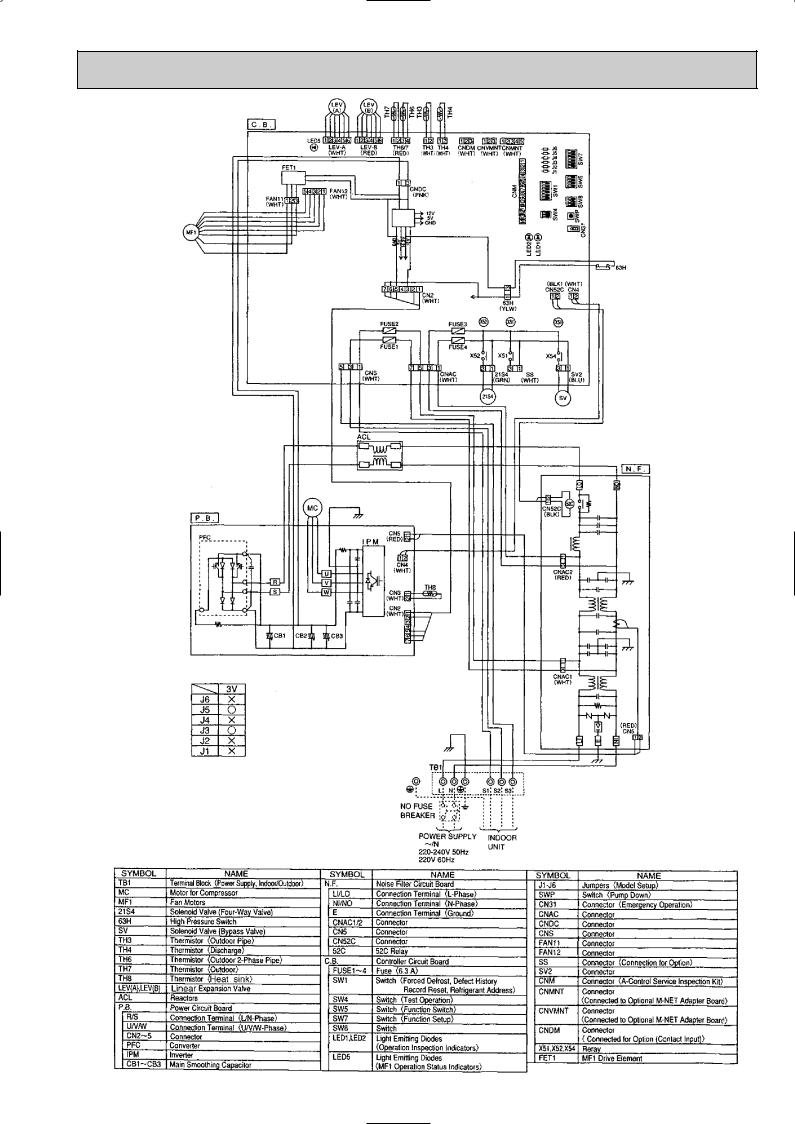
PUHZ-RP3VHA PUHZ-RP3VHA-A
9
, PLA-RP_AA(1).UK, PEA-RP_EA, PEAD-RP_EA, PEAD-RP_EA.UK TECHNICAL MANUAL")
PUHZ-RP4VHA PUHZ-RP5VHA PUHZ-RP6VHA PUHZ-RP4VHA-A PUHZ-RP5VHA-A PUHZ-RP6VHA-A
10
4 
 REFRIGERANT SYSTEM DIAGRAM
4-1. Checking operation statuses PUHZ-RP • HA
4-1-1. Measurement points and items
•The table and diagrams below show the measurement item for each measurement point, and the pressure and temperature near the ISO T1 standard operating conditions.
•Measure the temperature and pressure of each part by following the descriptions in the table.
•Measurement time: Be sure to wait until the refrigerant circuit has stabilized (30 minutes to 1 hour) before taking measurements.
|
Measurement item |
Pressure/temperature near JIS |
Measurement method, remarks |
|
|
standard operating conditions |
|||
|
|
|
||
A |
High pressure (MPa) |
COOL: 2.3 ~ 3.0 |
HEAT: 2.0 ~ 3.2 |
Connect the pressure gauge to the high-pressure check valve. |
|
|
|
|
|
B |
Low pressure (MPa) |
0.55 ~ 1.0 |
Connect the pressure gauge to the low-pressure check valve. |
|
|
|
|
|
|
C |
Discharge pipe temperature (:) |
50 ~ 100 |
Measured with piping surface thermometer. |
|
|
|
|
|
|
D |
Suction pipe temperature (:) |
-2 ~ +18 |
Measured with piping surface thermometer. |
|
|
|
|
|
|
E |
Indoor intake temperature (:) |
COOL: 27: HEAT: 20: |
Can be displayed on remote controller. |
|
|
|
|
|
|
F |
Indoor outlet temperature (:) |
COOL: 8 ~ 20 |
|
|
|
|
HEAT: 30 ~ 50 |
|
|
|
|
|
|
|
G |
Outdoor intake temperature (:) |
COOL: 35 |
HEAT: 7 |
Measured with piping surface thermometer. |
|
|
|
|
|
H |
Outdoor outlet temperature (:) |
COOL: 40 ~ 50 |
HEAT: 0 ~ 5 |
Measured with piping surface thermometer. |
|
|
|
|
|
Notes : The operation statuses vary depending on the compressor's operating frequency because units are inverter-type.
Outdoor
heat exchanger
Ball valve |
4-way valve |
A
B 
D
C
Indoor heat |
|
|
|
exchanger |
Linear |
Power |
Compressor |
|
expansion |
||
|
valve B |
receiver |
Linear |
|
Stop valve |
|
expansion |
|
(with service port) |
|
valve A |
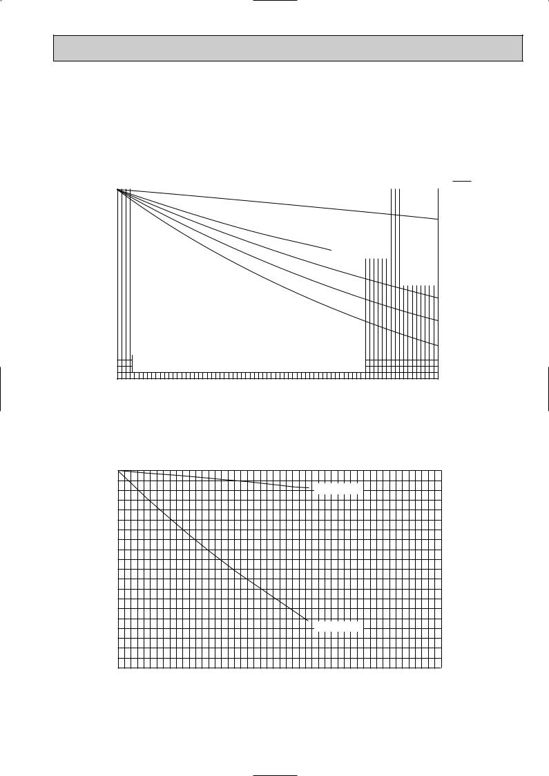
4-1-2. Operation pressure ranges
Discharge pressure (MPa)
Permissible operation range Normal operation range
4.5
4 |
|
3.5 |
Overload operation |
|
|
3 |
|
2.5 |
Standard operation |
2
1.5
1
0.5
0
0 |
0.2 |
0.4 |
0.6 |
0.8 |
1 |
1.2 |
Suction pressure (MPa)
11

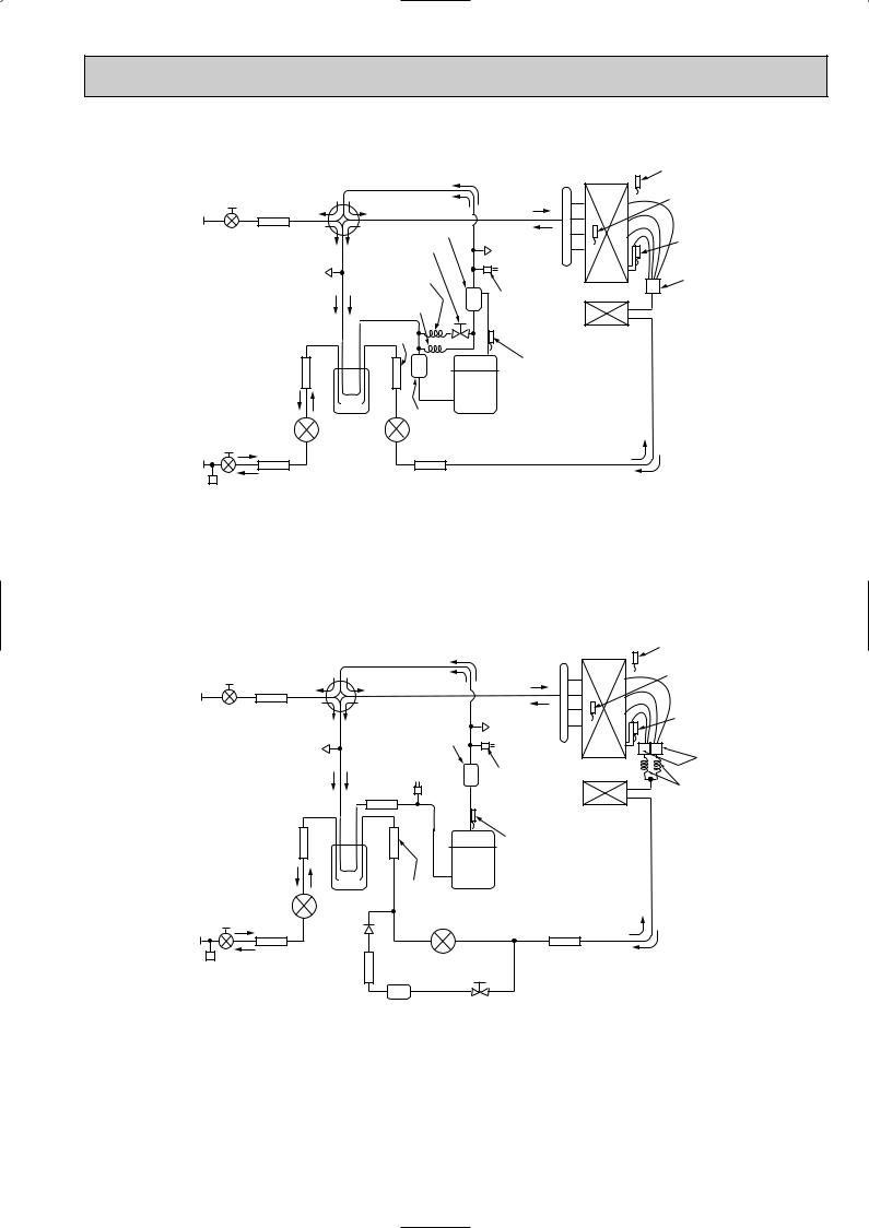
4-2. Refrigerant System Diagram
PLA-RP3AA
PLA-RP3AA1 PLA-RP3AA.UK PLA-RP3AA1.UK PEA-RP3EA.TH-A PEAD-RP3EA.UK PEAD-RP3EA1.UK
PLA-RP4AA
PLA-RP4AA1 PLA-RP4AA.UK PLA-RP4AA1.UK PEA-RP4EA.TH-A PEAD-RP4EA.UK PEAD-RP4EA1.UK
Heat exchanger
PLA-RP5AA
PLA-RP5AA1 PLA-RP5AA.UK PLA-RP5AA1.UK PEA-RP5EA.TH-A PEAD-RP5EA.UK PEAD-RP5EA1.UK
Strainer #50
PLA-RP6AA
PLA-RP6AA1 PLA-RP6AA.UK PLA-RP6AA1.UK PEA-RP6EA.TH-A PEAD-RP6EA.UK PEAD-RP6EA1.UK
|
Refrigerant GAS pipe connection |
|
(Flare) |
|
Condenser/evaporator |
|
temperature thermistor |
|
(TH5) |
|
Refrigerant flow in cooling |
|
Refrigerant flow in heating |
|
Refrigerant LIQUID pipe connection |
|
(Flare) |
|
Pipe temperature |
Room temperature |
thermistor/liquid |
thermistor (TH1) |
(TH2) |
Distributor |
Strainer |
|
#50 |
||
with strainer |
||
|
||
#50 |
|
12
PUHZ-RP3VHA |
|
|
|
Heat exchanger |
Thermistor TH7 |
PUHZ-RP3VHA-A |
|
|
|
||
|
|
|
(Outdoor) |
||
|
|
|
|
||
|
|
|
|
|
|
Ball valve Strainer |
4-way valve |
|
Thermistor TH6 |
||
Refrigerant GAS pipe |
#50 |
|
|
|
(Outdoor 2-phase pipe) |
|
|
|
|
||
|
|
|
|
|
|
connection(5/8F) |
|
|
Oil separator |
|
|
|
|
|
Service port |
Thermistor TH3 |
|
|
|
|
Bypass valve |
||
|
|
|
(High pressure) |
(Outdoor pipe) |
|
|
|
|
|
||
|
Service port |
|
Capillary tube |
|
|
|
(Low pressure) |
O.D.4.0OI.D.2.4OL500 |
|
Distributor |
|
|
|
Capillary tube |
High pressure |
|
|
|
|
switch 63H |
|
||
|
|
O.D.2.5OI.D.0.6OL1000 |
|
||
|
|
|
|
||
|
|
|
Strainer |
|
|
|
|
|
#100 |
|
|
|
|
|
|
Thermistor TH4 |
|
|
Strainer |
|
|
(Discharge) |
|
|
#100 |
|
|
|
|
|
|
Power |
Muffler Compressor |
|
|
Stop valve |
|
receiver |
|
|
|
|
|
Linear expansion valve A |
|
||
(with service port) |
Linear |
|
|||
|
|
|
|||
Refrigerant LIQUID pipe |
|
expansion |
|
|
|
|
valve B |
|
|
|
|
connection(3/8F) |
|
|
|
|
|
Strainer |
|
Strainer |
|
|
|
|
|
|
|
||
|
#100 |
|
#100 |
|
|
PUHZ-RP4VHA PUHZ-RP5VHA PUHZ-RP6VHA PUHZ-RP4VHA-A PUHZ-RP5VHA-A PUHZ-RP6VHA-A
|
Thermistor TH7 |
Heat exchanger |
(Outdoor) |
|
|
Ball valve Strainer |
4-way valve |
|
Thermistor TH6 |
|
|
|
|
(Outdoor 2-phase pipe) |
|||
Refrigerant GAS pipe |
#50 |
|
|
|
|
|
|
|
|
|
|
||
connection(5/8F) |
|
|
|
|
|
Thermistor TH3 |
|
|
|
|
|
Service port |
|
|
|
|
|
|
(Outdoor pipe) |
|
|
|
|
|
|
(High pressure) |
|
|
|
Service port |
|
Muffler |
|
|
|
|
|
|
|
|
|
|
|
(Low pressure) |
|
Low pressure |
|
Distributor |
|
|
|
|
|
|
|
|
|
|
|
switch 63L |
High pressure |
|
|
|
|
|
Strainer |
|
|
|
|
|
|
switch 63H |
Capillary tube |
|
|
|
|
|
#100 |
|
(O.D.4.0OI.D.3.0OL200)O2pcs |
|
|
Strainer |
|
|
Thermistor TH4 |
|
|
|
|
|
(Discharge) |
|
|
|
|
#100 |
|
|
|
|
|
|
|
|
|
|
|
|
|
|
Power |
Strainer |
Compressor |
|
|
Linear expansion valve B |
#100 |
|
|||
|
Stop valve |
receiver |
|
|
||
|
|
Linear expansion valve A |
|
|||
|
(with service port) |
Restrictor |
|
|||
Refrigerant LIQUID pipe |
|
|
|
|
||
|
valve |
|
|
|
||
connection(3/8F) |
|
Strainer |
|
|
Strainer |
|
|
|
|
|
|
||
|
|
#100 |
Strainer |
|
#100 |
|
|
|
|
#100 |
|
|
|
|
|
|
|
Replace filter |
Bypass valve |
|
|
|
|
|
|
|
|
13
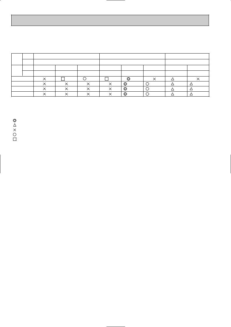
4-3. Applicable extension pipe for each model
4-3-1. 1:1 system
(a) Pipe length
<Table 1> Pipe length for 1:1 system
Liquid |
OD |
|
[6.35 |
|
|
[9.52 |
|
|
[12.7 |
|
pipe |
Thick- |
|
t0.8 |
|
|
t0.8 |
|
|
t0.8 |
|
(mm) |
|
|
|
|
|
|||||
ness |
|
|
|
|
|
|||||
Gas |
OD |
[9.52 |
[12.7 |
[15.88 |
[12.7 |
[15.88 |
[19.05 |
[15.88 |
[19.05 |
|
pipe |
Thick- |
t0.8 |
t0.8 |
t1.0 |
t0.8 |
t1.0 |
t1.0 |
t1.0 |
t1.0 |
|
(mm) |
||||||||||
ness |
||||||||||
RP3 |
|
10m |
10m |
30m |
50m |
|
30m |
|
||
RP4 |
|
|
|
|
75m (*2) |
50m (*1) |
50m |
50m (*1) |
||
RP5 |
|
|
|
|
75m (*2) |
50m (*1) |
50m |
50m (*1) |
||
RP6 |
|
|
|
|
75m (*2) |
50m (*1) |
50m |
50m (*1) |
||
*1: Set DIP SW8-1 on outdoor unit controller board to ON.
*2: The maximum length is 50 m in case of using existing pipes.
*3: The height difference between indoor and outdoor unit should be kept within 30 m for all models.
[Marks in the table above]
:Normal piping
:It can be used, however, additional refrigerant charge is required when the pipe length exceeds 20m.  Refer to table 4.
:It cannot be used.
:It can be used.
:It can be used, however, the capacity is lowered.  Refer to (C) Capacity correction.
(b)Adjusting the amount of refrigerant
•Additional refrigerant charge is not necessary for the pipe length up to 30 m. When the pipe length exceeds 30 m or service (refrigerant replacement) is performed, charge proper amount of refrigerant for each pipe length referring to table below. Use refrigerant R410A. Use charge hose exclusive for R410A.
•When charging additional refrigerant, charge the refrigerant from low-pressure side of the port valve using a safety charger.
•Make sure that air purge for this unit at refrigerant replacement is performed from both high-pressure check valve and service port. (If air purge is performed only from one of them, air in not purged enough.)
•When replacing refrigerant, charge the refrigerant from service port. When charged refrigerant is less than specified amount, charge the refrigerant again from low pressure side of the port valve using a safety charger.
•Tighten the service port cap (nut) of stop valve firmly. The tightening torque is 12 to 16 N·m. (For the prevention of slow-leak)
•Check additional refrigerant charging amount referring to table 4 when liquid pipe is one size larger than standard diameter, and table 2 when the pipe is standard diameter.
<Table 2> Additional refrigerant charging amount for pipe of standard diameter |
|
|
|
|
|
|||||||||||
|
|
|
|
|
Permitted |
|
Additional refrigerant charging amount for pipe |
Number of |
Height |
|
||||||
Outdoor unit |
|
|
|
length exceeding 30 m (kg) |
|
|||||||||||
|
pipe length |
|
|
|
|
|
|
|
bends |
difference |
|
|||||
|
|
|
|
|
|
31 — 40m |
41 — 50m |
51 — 60m |
61 — 75m |
|
||||||
|
|
|
|
|
|
|
|
|
|
|
||||||
|
|
|
|
|
|
|
|
|
|
|
||||||
PUHZ-RP3 |
|
50m or below |
|
0.6Kg |
1.2Kg |
— |
— |
15 |
30m or |
|
||||||
PUHZ-RP4 — |
RP6 |
|
75m or below |
|
0.6kg |
1.2kg |
1.8kg |
2.4kg |
above |
|
||||||
|
|
|
|
|||||||||||||
|
|
|
|
|
|
|
|
|
|
|
|
|
|
|
|
|
<Table 3> |
|
|
|
|
|
|
|
|
|
|
|
|
|
|
|
|
Outdoor unit |
|
Permitted |
Additional refrigerant charging amount for recharging (above) and pipe length exceeding 30m (below) (kg) |
|||||||||||||
|
pipe length |
10m or below |
11 — 20m |
21 — 30m |
31 — 40m |
41 — 50m |
51 — 60m |
61 — 75m |
||||||||
|
|
|
|
|
||||||||||||
|
|
|
|
|
|
|
|
|
|
|
|
|
|
|
|
|
PUHZ-RP3 |
|
50m or below |
|
3.1 |
3.3 |
3.5 |
4.1 |
4.7 |
— |
— |
||||||
|
|
0.6 |
1.2 |
— |
— |
|||||||||||
|
|
|
|
|
|
|
|
|
|
|
|
|||||
|
|
|
|
|
|
|
|
|
|
|
|
|
|
|
|
|
PUHZ-RP4 — |
RP6 |
|
75m or below |
|
5.1 |
5.3 |
5.5 |
6.1 |
6.7 |
7.3 |
7.9 |
|||||
|
|
0.6 |
1.2 |
1.8 |
2.4 |
|||||||||||
|
|
|
|
|
|
|
|
|
|
|
|
|||||
|
|
|
|
|
|
|
|
|
||||||||
<Table 4> Additional refrigerant charging amount for liquid pipe which is one size larger than |
|
|
|
|||||||||||||
standard diameter |
|
|
|
|
|
|
|
|
|
|
|
|
||||
|
Liquid pipe dia |
Chargeless |
Max. pipe length |
Additional refrigerant charging amount |
|
|
|
|
||||||||
|
|
|
|
|
|
|
|
|
|
|
|
|
|
|
|
|
RP3 |
[12.7 |
|
20m |
|
30m |
|
100 g addition per 1 m when pipe length exceeds 20 m |
|
|
|
|
|||||
RP4 — RP6 |
[12.7 |
|
20m |
|
50m |
|
100 g addition per 1 m when pipe length exceeds 20 m |
|
|
|
|
|||||
14
(c) Capacity correction
Cooling and heating capacity is lowered according to pipe length. Capacity can be obtained by referring to the capacity curves below. When the diameter of gas pipe is one size smaller than standard diameter, cooling capacity is lowered comparing to the standard diameter. The lowered capacity can be obtained by referring to capacity curves for gas pipe which is one size smaller than standard size.
Corrected pipe length (m) = actual pipe length (m) + number of bends x 0.3 (m)
1 Capacity curves for PUHZ-RP • HA model <Standard size> |
|
|
|
|
|
|
|
|
|
|
|
|
Cooling |
||||||||||||||||||||||||||||||||||||||||||||||||||||||||||||||||
|
|
|
|
|
|
|
|
|
|
|
|
||||||||||||||||||||||||||||||||||||||||||||||||||||||||||||||||||
|
100 |
|
|
|
|
|
|
|
|
|
|
|
|
|
|
|
|
|
|
|
|
|
|
|
|
|
|
|
|
|
|
|
|
|
|
|
|
|
|
|
|
|
|
|
|
|
|
|
|
|
|
|
|
|
|
|
|
|
|
|
|
|
|
|
|
|
|
|
|
|
|
|
|
|
|
|
Heating |
|
|
|
|
|
|
|
|
|
|
|
|
|
|
|
|
|
|
|
|
|
|
|
|
|
|
|
|
|
|
|
|
|
|
|
|
|
|
|
|
|
|
|
|
|
|
|
|
|
|
|
|
|
|
|
|
|
|
|
|
|
|
|
|
|
|
|
|
|
|
|
|
|
|
Heating RP3, 4, 5 |
|||
|
|
|
|
|
|
|
|
|
|
|
|
|
|
|
|
|
|
|
|
|
|
|
|
|
|
|
|
|
|
|
|
|
|
|
|
|
|
|
|
|
|
|
|
|
|
|
|
|
|
|
|
|
|
|
|
|
|
|
|
|
|
|
|
|
|
|
|
|
|
|
|
|
|
||||
|
95 |
|
|
|
|
|
|
|
|
|
|
|
|
|
|
|
|
|
|
|
|
|
|
|
|
|
|
|
|
|
|
|
|
|
|
|
|
|
|
|
|
|
|
|
|
|
|
|
|
|
|
|
|
|
|
|
|
|
|
|
|
|
|
|
|
|
|
|
|
|
|
|
|
|
|||
|
|
|
|
|
|
|
|
|
|
|
|
|
|
|
|
|
|
|
|
|
|
|
|
|
|
|
|
|
|
|
|
|
|
|
|
|
|
|
|
|
|
|
|
|
|
|
|
|
|
|
|
|
|
|
|
|
|
|
|
|
|
|
|
|
|
|
|
|
|
|
|
|
|
||||
|
|
|
|
|
|
|
|
|
|
|
|
|
|
|
|
|
|
|
|
|
|
|
|
|
|
|
|
|
|
|
|
|
|
|
|
|
|
|
|
|
|
|
|
|
|
|
|
|
|
|
|
|
|
|
|
|
|
|
|
|
|
|
|
|
|
|
|
|
|
|
|
|
|
||||
|
|
|
|
|
|
|
|
|
|
|
|
|
|
|
|
|
|
|
|
|
|
|
|
|
|
|
|
|
|
|
|
|
|
|
|
|
|
|
|
|
|
|
|
|
|
|
|
|
|
|
|
|
|
|
|
|
|
|
|
|
|
|
|
|
|
|
|
|
|
|
|
|
|
||||
|
|
|
|
|
|
|
|
|
|
|
|
|
|
|
|
|
|
|
|
|
|
|
|
|
|
|
|
|
|
|
|
|
|
|
|
|
|
|
|
|
|
|
|
|
|
|
|
|
|
|
|
|
|
|
|
|
|
|
|
|
|
|
|
|
|
|
|
|
|
|
|
|
|
||||
|
|
|
|
|
|
|
|
|
|
|
|
|
|
|
|
|
|
|
|
|
|
|
|
|
|
|
|
|
|
|
|
|
|
|
|
|
|
|
|
|
|
|
|
|
|
|
|
|
|
|
|
|
|
|
|
|
|
|
|
|
|
|
|
|
|
|
|
|
|
|
|
|
|
|
and 6 models |
||
|
|
|
|
|
|
|
|
|
|
|
|
|
|
|
|
|
|
|
|
|
|
|
|
|
|
|
|
|
|
|
|
|
|
|
|
|
|
|
|
|
|
|
|
|
|
|
|
|
|
|
|
|
|
|
|
|
|
|
|
|
|
|
|
|
|
|
|
|
|
|
|
|
|
|
|||
|
|
|
|
|
|
|
|
|
|
|
|
|
|
|
|
|
|
|
|
|
|
|
|
|
|
|
|
|
|
|
|
|
|
|
|
|
|
|
|
|
|
|
|
|
|
|
|
|
|
|
|
|
|
|
|
|
|
|
|
|
|
|
|
|
|
|
|
|
|
|
|
|
|
|
(Up to 55m for |
||
|
|
|
|
|
|
|
|
|
|
|
|
|
|
|
|
|
|
|
|
|
|
|
|
|
|
|
|
|
|
|
|
|
|
|
|
|
|
|
|
|
|
|
|
|
|
|
|
|
|
|
|
|
|
|
|
|
|
|
|
|
|
|
|
|
|
|
|
|
|
|
|
|
|
|
|||
ratio [%] |
90 |
|
|
|
|
|
|
|
|
|
|
|
|
|
|
|
|
|
|
|
|
|
|
|
|
|
|
|
|
|
|
|
|
|
|
|
|
|
|
|
|
|
|
|
|
|
|
|
|
|
|
|
RP3 model |
|
|
|
|
|
|
|
|
|
|
RP3 model) |
|||||||||||||
|
|
|
|
|
|
|
|
|
|
|
|
|
|
|
|
|
|
|
|
|
|
|
|
|
|
|
|
|
|
|
|
|
|
|
|
|
|
|
|
|
|
|
|
|
|
|
|
|
|
|
|
|
|
|
|
|
|
|
|
|
|||||||||||||||||
|
|
|
|
|
|
|
|
|
|
|
|
|
|
|
|
|
|
|
|
|
|
|
|
|
|
|
|
|
|
|
|
|
|
|
|
|
|
|
|
|
|
|
|
|
|
|
|
|
|
|
|
|
|
|
|
|
|
|
|
|
|
|
|
||||||||||||||
|
|
|
|
|
|
|
|
|
|
|
|
|
|
|
|
|
|
|
|
|
|
|
|
|
|
|
|
|
|
|
|
|
|
|
|
|
|
|
|
|
|
|
|
|
|
|
|
|
|
|
|
|
|
|
|
|
|
|
|
|
|
|
|
|
|
|
|
|
|
|
|
|
|
|
|
|
|
|
|
|
|
|
|
|
|
|
|
|
|
|
|
|
|
|
|
|
|
|
|
|
|
|
|
|
|
|
|
|
|
|
|
|
|
|
|
|
|
|
|
|
|
|
|
|
|
|
|
|
|
|
|
|
|
|
|
|
|
|
|
|
|
|
|
|
|
|
|
|
|
|
|
|
|
||
85 |
|
|
|
|
|
|
|
|
|
|
|
|
|
|
|
|
|
|
|
|
|
|
|
|
|
|
|
|
|
|
|
|
|
|
|
|
|
|
|
|
|
|
|
|
|
|
|
|
|
|
|
|
|
|
|
|
|
|
|
|
|
|
|
|
Cooling |
|
|
|
|
||||||||
|
|
|
|
|
|
|
|
|
|
|
|
|
|
|
|
|
|
|
|
|
|
|
|
|
|
|
|
|
|
|
|
|
|
|
|
|
|
|
|
|
|
|
|
|
|
|
|
|
|
|
|
|
|
|
|
|
|
|
|
|
|
|
|
|
|||||||||||||
Capacity |
|
|
|
|
|
|
|
|
|
|
|
|
|
|
|
|
|
|
|
|
|
|
|
|
|
|
|
|
|
|
|
|
|
|
|
|
|
|
|
|
|
|
|
|
|
|
|
|
|
|
|
|
|
|
|
|
|
|
|
|
|
|
|
|
|
|
|
|
|
|
|
|
|
RP4 model |
|||
|
|
|
|
|
|
|
|
|
|
|
|
|
|
|
|
|
|
|
|
|
|
|
|
|
|
|
|
|
|
|
|
|
|
|
|
|
|
|
|
|
|
|
|
|
|
|
|
|
|
|
|
|
|
|
|
|
|
|
|
|
|
|
|
|
|
|
|
|
|
|
|
|
|||||
80 |
|
|
|
|
|
|
|
|
|
|
|
|
|
|
|
|
|
|
|
|
|
|
|
|
|
|
|
|
|
|
|
|
|
|
|
|
|
|
|
|
|
|
|
|
|
|
|
|
|
|
|
|
|
|
|
|
|
|
|
|
|
|
|
|
|
|
|
|
|
|
|
|
|
||||
|
|
|
|
|
|
|
|
|
|
|
|
|
|
|
|
|
|
|
|
|
|
|
|
|
|
|
|
|
|
|
|
|
|
|
|
|
|
|
|
|
|
|
|
|
|
|
|
|
|
|
|
|
|
|
|
|
|
|
|
|
|
|
|
|
|
|
|
|
|
|
|
|
|
|
|||
|
75 |
|
|
|
|
|
|
|
|
|
|
|
|
|
|
|
|
|
|
|
|
|
|
|
|
|
|
|
|
|
|
|
|
|
|
|
|
|
|
|
|
|
|
|
|
|
|
|
|
|
|
|
|
|
|
|
|
|
|
|
|
|
|
|
|
|
|
|
|
|
|
|
|
|
RP5 model |
||
|
|
|
|
|
|
|
|
|
|
|
|
|
|
|
|
|
|
|
|
|
|
|
|
|
|
|
|
|
|
|
|
|
|
|
|
|
|
|
|
|
|
|
|
|
|
|
|
|
|
|
|
|
|
|
|
|
|
|
|
|
|
|
|
|
|
|
|
|
|
|
|
|
|
||||
|
|
|
|
|
|
|
|
|
|
|
|
|
|
|
|
|
|
|
|
|
|
|
|
|
|
|
|
|
|
|
|
|
|
|
|
|
|
|
|
|
|
|
|
|
|
|
|
|
|
|
|
|
|
|
|
|
|
|
|
|
|
|
|
|
|
|
|
|
|
|
|
|
|
||||
|
|
|
|
|
|
|
|
|
|
|
|
|
|
|
|
|
|
|
|
|
|
|
|
|
|
|
|
|
|
|
|
|
|
|
|
|
|
|
|
|
|
|
|
|
|
|
|
|
|
|
|
|
|
|
|
|
|
|
|
|
|
|
|
|
|
|
|
|
|
|
|
|
|
||||
|
|
|
|
|
|
|
|
|
|
|
|
|
|
|
|
|
|
|
|
|
|
|
|
|
|
|
|
|
|
|
|
|
|
|
|
|
|
|
|
|
|
|
|
|
|
|
|
|
|
|
|
|
|
|
|
|
|
|
|
|
|
|
|
|
|
|
|
|
|
|
|
|
|
RP6 model |
|||
|
|
|
|
|
|
|
|
|
|
|
|
|
|
|
|
|
|
|
|
|
|
|
|
|
|
|
|
|
|
|
|
|
|
|
|
|
|
|
|
|
|
|
|
|
|
|
|
|
|
|
|
|
|
|
|
|
|
|
|
|
|
|
|
|
|
|
|
|
|
|
|
|
|
||||
|
|
|
|
|
|
|
|
|
|
|
|
|
|
|
|
|
|
|
|
|
|
|
|
|
|
|
|
|
|
|
|
|
|
|
|
|
|
|
|
|
|
|
|
|
|
|
|
|
|
|
|
|
|
|
|
|
|
|
|
|
|
|
|
|
|
|
|
|
|
|
|
|
|
||||
|
|
|
|
|
|
|
|
|
|
|
|
|
|
|
|
|
|
|
|
|
|
|
|
|
|
|
|
|
|
|
|
|
|
|
|
|
|
|
|
|
|
|
|
|
|
|
|
|
|
|
|
|
|
|
|
|
|
|
|
|
|
|
|
|
|
|
|
|
|
|
|
|
|
||||
|
|
|
|
|
|
|
|
|
|
|
|
|
|
|
|
|
|
|
|
|
|
|
|
|
|
|
|
|
|
|
|
|
|
|
|
|
|
|
|
|
|
|
|
|
|
|
|
|
|
|
|
|
|
|
|
|
|
|
|
|
|
|
|
|
|
|
|
|
|
|
|
|
|
|
|
|
|
Note: The permitted pipe length is up to 55m for RP3 model.
70
5 |
10 |
15 |
20 |
25 |
30 |
35 |
40 |
45 |
50 |
55 |
60 |
65 |
70 |
75 |
80 |
Corrected pipe length
2Capacity curve for PUHZ-RP3 model
<When gas pipe is one size smaller than standard size>
|
100 |
|
|
|
|
|
|
|
|
|
|
|
|
|
|
|
|
|
|
Heating RP3 |
|
|
|
|
95 |
|
|
|
|
|
|
|
|
|
|
ratio [%] |
90 |
|
|
|
|
|
|
|
|
|
|
Capacity |
|
|
|
|
|
|
|
|
|
|
|
|
|
|
|
|
|
|
|
|
|
|
|
|
85 |
|
|
|
|
|
|
Cooling RP3 |
|
|
|
|
|
|
|
|
|
|
|
|
|
|
|
|
80 |
|
|
|
|
|
|
|
|
|
|
|
5 |
10 |
15 |
20 |
25 |
30 |
35 |
40 |
45 |
50 |
55 |
Corrected pipe length
3 When gas pipe is one size larger than standard size for PUHZ-RP4, 5 and 6.
1 Capacity can be obtained by referring to capacity curves of standard size.
15

4-3-2. Synchronized twin and triple
(a)Pipe length
Please note that refrigerant piping length, bend number and height difference of indoor units are specified for each unit combination.
Note: Be sure to use our Multi-distributor for distributing pipe to use existing piping.
<Table 5>
|
|
Synchronized twin |
Permitted total piping |
Chargeless piping |
Indoor unit’s height |
Bend number |
||
|
|
length |
A + B + C |
length |
A + B + C |
difference [B and C] |
w 2 |
|
|
|
|
||||||
Outdoor |
|
PUHZ-RP3VHA |
50 m or less |
30 m or less |
8 m or less |
15 at most |
||
unit |
|
PUHZ-RP4~6VHA |
75 m or less |
|||||
|
|
|
|
|
||||
<Table 6> |
|
|
|
|
|
|
|
|
|
|
Synchronized twin |
Permitted total piping |
Charge-less piping |
Indoor unit’s height difference |
Bend number |
||
|
|
length |
A + B + C + D |
length |
A + B + C + D |
[B and C] [C and D] [B and D] |
w 2 |
|
|
|
|
||||||
Outdoor |
|
PUHZ-RP6VHA |
70 m or less |
30 m or less |
8 m or less |
15 at most |
||
unit |
|
|||||||
|
|
|
|
|
|
|
|
|
|
|
|
|
|
|
|
|
|
Note 1: If total piping length exceeds charge-less piping length of 30 m, charge additional refrigerant according to the table 7.
<Table 7> |
|
|
|
|
|
|
|
|
|
w Charge additional |
|
|
|
|
A + B + C (+D) |
|
|
|
|||
|
|
|
|
|
|
|
|
|
|
refrigerant from |
Outdoor unit |
|
Additional refrigerant to be charged (kg) |
|
|||||||
|
|
the check valve |
||||||||
|
30 m or less |
|
31 - 40 m |
|
41 - 50 m |
51 - 60 m |
|
61 - 75 m |
connected to the |
|
PUHZ-RP3VHA |
Not required |
|
0.6 |
|
1.2 |
|
|
|
|
pipe of low-pressure |
|
|
|
|
|
|
|
side in indoor unit. |
|||
PUHZ-RP4~6VHA |
|
1.8 |
|
2.4 |
||||||
|
|
|
|
|
|
|
|
|||
Note 2: Bends number (w 2) should be within 8 for each combination, A + B, A +C and A + D, and 15 in all.
Note 3: Height difference between indoor and outdoor unit is referred to no matter which unit is located higher or lower.
<Table 8> Pipe length for twin of RP 3 - 6 (Piping length: A + B + C)
|
|
|
RP3 Twin (RP1.6 2) |
RP4 Twin (RP2 2) |
RP5 Twin (RP2.5 2) |
RP6 Twin (RP3 2) |
|
||||
|
|
|
|
|
|
|
|
|
|
|
|
|
|
|
|
|
|
Main pipe diameter [A] |
|
|
|
|
|
|
|
|
|
|
|
|
|
|
|
|
|
|
|
|
Liquid [6.35 |
Liquid [9.52 |
Liquid [9.52 |
Liquid [12.7 |
Liquid [9.52 |
Liquid [12.7 |
Liquid [9.52 |
Liquid [12.7 |
|
|
|
|
Gas [12.7 |
Gas [15.88 |
Gas [15.88 |
Gas [19.05 |
Gas [15.88 |
Gas [19.05 |
Gas [15.88 |
Gas [19.05 |
|
Branch pipe |
Liquid [6.35 |
|
50 m |
75 m( 2) |
50 m( 1) |
|
|
|
|
|
|
|
Gas |
[12.7 |
|
||||||||
diameter |
|
|
|
|
|
|
|
|
|
||
Liquid [9.52 |
|
50 m |
50 m |
50 m( 1) |
75 m( 2) |
50 m( 1) |
75 m( 2) |
50 m( 1) |
|
||
[B and C] |
|
||||||||||
Gas |
[15.88 |
|
|||||||||
|
|
|
|
|
|
|
|
|
|
||
|
Liquid [12.7 |
|
|
|
|
|
|
|
|
|
|
|
Gas |
[19.05 |
|
||||||||
|
|
|
|
|
|
|
|
|
|
||
<Table 9> Pipe length for triple of RP6 (Piping length: A + B + C + D) |
|
|
|
|
|
||||||
|
|
|
Main pipe diameter [A] |
1 ··· Set DIP SW8-1 on outdoor unit control circuit board to ON. |
|||||||
|
|
|
Liquid [9.52 |
Liquid [12.7 |
2 ··· When using existing piping, pipe length should be 50 m at most. |
||||||
|
|
|
Gas [15.88 |
Gas [19.05 |
3 ··· Height difference between indoor and outdoor unit should be |
||||||
Branch pipe |
Liquid [6.35 |
75 m( 2) |
50 m( 1) |
|
kept within 30 m in every case. |
|
|
|
|||
|
Gas |
[12.7 |
|
|
|
|
|
|
|
||
diameter |
|
|
[Marks in table] |
|
|
|
|
|
|||
Liquid [9.52 |
|
|
|
|
|
|
|
||||
[B,C and D] |
50 m |
50 m( 1) |
··· Normal piping |
|
|
|
|
||||
Gas |
[15.88 |
|
|
|
|
||||||
|
|
··· It can be used with some changes of piping length and the |
|||||||||
|
Liquid [12.7 |
|
|
amount of refrigerant to be charged. |
|
|
|
||||
|
Gas |
[19.05 |
··· It cannot be used. |
|
|
|
|
||||
|
|
|
|
|
|
|
|||||
16
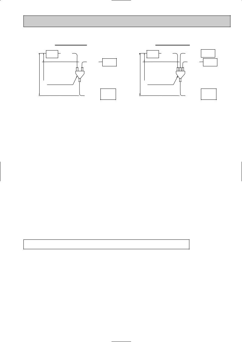
30 m or less 1 m or less
Synchronized twin
Indoor |
Branch |
|
pipe B |
||
unit |
||
|
Branch |
Indoor |
pipe C |
unit |
Optional distributing pipe Multi-distributor
Main |
Outdoor |
|
unit |
||
pipe A |
||
|
30 m or less 1 m or less
Synchronized triple |
|
||
Indoor |
Branch |
Branch |
Indoor |
unit |
pipe B |
pipe C |
unit |
|
|
Branch |
Indoor |
|
|
pipe D |
unit |
Optional distributing pipe Multi-distributor
Main |
Outdoor |
|
unit |
||
pipe A |
||
|
1.Keep Stop valve in outdoor unit fully closed (as it is shipped), and after completing refrigerant piping connection, conduct air purge from service port of stop valve at outdoor unit.
2.After air purging, make the valve rod of stop valve at outdoor unit fully open. Now refrigerating cycle is complete between indoor and outdoor unit. Handle stop valve following the indication on outdoor unit.
Caution:
•Be sure to apply refrigerating oil to flare sheet face. Never apply it to screws. (As it causes flare nut loosening.)
•Use double spanner for piping connection.
•Be sure to check gas leak by using leak detector or soapy water.
•Use attached parts for refrigerant piping to provide correct insulation to the connection of indoor unit side in accordance with attached explanation sheet.
•Be sure to provide anoxidized brazing.
(b) Adjusting the amount of refrigerant oil
(i)In case of RP 3 twin
Check the additional refrigerant oil to be charged referring to table 2 when using pipe of size referred in table 8.
(ii)In case of RP4 - 6 twin or RP6 triple
When using liquid pipe one size larger than standard diameter for main pipe A, calculate the amount of additional refrigerant oil referring to 2 below.
1When using piping of standard diameter or gas pipe one size larger than standard diameter for main pipe A. Check the additional refrigerant oil to be charged referring to table 2 like 1:1 system.
2When using liquid pipe one size larger than standard diameter for main pipe A. [In case of RP4-6 using liquid pipe of [12.7]
•When total length of extension pipe (main pipe and branch pipe) is less than 20 m. No adjustment is required for refrigerant oil. (Chargeless)
•When total length of extension pipe (main pipe and branch pipe) is more than 20 m.
Calculate the amount of additional refrigerant oil, referred to as  W (g) in the following, using the equation below and add proper amount of refrigerant oil. If
  W is less than or equal to 0, no additional charge is required. (Chargeless)
[Additional refrigerant oil]  W (g) = {100(g) L1} + {60(g) L2} + {30(g) L3} - 2000(g)
Note: Put “0” in L1-3 if it is not used.
L1: Liquid pipe length of [12.7 (m) L2: Liquid pipe length of [9.52 (m) L3: Liquid pipe length of [6.35 (m)
(c) Capacity correction
Apply pipe length between indoor and outdoor unit which is the longest of all for the calculation of capacity lowering according to each pipe length.
17
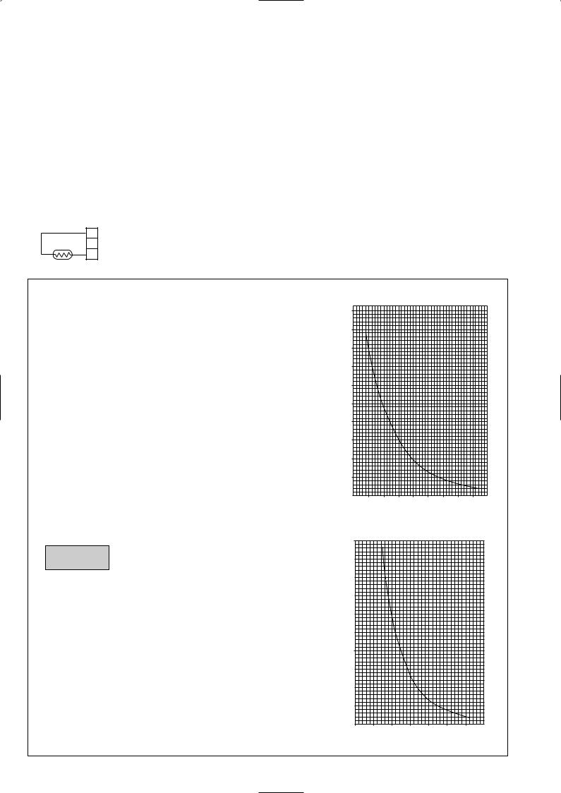
5 |
|
|
HOW TO CHECK THE PARTS |
|||||
|
|
|
|
|
|
|
|
|
5-1. INDOOR UNIT |
|
|
|
|||||
• Common parts |
|
|
|
|
||||
|
|
|
|
|
||||
Parts name |
|
|
|
Check points |
||||
|
|
|
|
|
||||
Room temperature |
|
Disconnect the connector then measure the resistance using a tester. |
||||||
thermistor |
(TH1) |
|
(Surrounding temperature 10:~30:) |
|
|
|||
Pipe temperature |
|
|
|
|
|
|||
thermistor |
(TH2) |
|
Normal |
Abnormal |
|
(Refer to below for a detail.) |
||
|
|
|
|
|
|
|||
Condenser/evaporator |
|
|
|
|
||||
|
4.3k"~9.6k" |
Open or short |
|
|||||
|
|
|
||||||
temperature thermistor |
|
|
|
|
|
|||
|
|
|
|
|
||||
|
|
|
(TH5) |
|
|
|
|
|
|
|
|
|
|
||||
Drain sensor |
|
Measure the resistance between the terminals using a tester. |
||||||
|
|
|
1 |
|
Measure the resistance after 3 minutes have passed since the power supply was intercepted. |
|||
|
|
|
|
(Surrounding temperature 0:~60:) |
|
|
||
|
|
|
2 |
|
|
|
|
|
|
|
|
|
Normal |
Abnormal |
|
|
|
|
|
|
3 |
|
|
|
||
|
|
|
|
|
|
|
(Refer to below for a detail.) |
|
|
|
|
|
0.6k"~6.0k" |
Open or short |
|
||
|
|
|
|
|
|
|||
|
|
|
|
|
|
|
|
|
<Thermistor Characteristic graph>
|
Thermistor for |
|
|
Room temperature thermistor(TH1) |
|||||||
|
lower temperature |
|
Pipe temperature thermistor(TH2) |
||||||||
|
|
|
|
|
Condenser/evaporator temperature |
||||||
|
|
|
|
|
|||||||
|
|
|
|
|
thermistor(TH5) |
||||||
Thermistor R0=15kΩ ± 3% |
|
|
|||||||||
Fixed number of B=3480kΩ ± 2% |
|
||||||||||
Rt=15exp { 3480( |
1 |
|
|
|
|
1 |
) } |
||||
273+t |
273 |
||||||||||
|
|
|
|
||||||||
0: |
15kΩ |
|
|
|
|
|
|
|
|
||
10: |
9.6kΩ |
|
|
|
|
|
|
|
|
||
20: |
6.3kΩ |
|
|
|
|
|
|
|
|
||
25: |
5.2kΩ |
|
|
|
|
|
|
|
|
||
30: |
4.3kΩ |
|
|
|
|
|
|
|
|
||
40: |
3.0kΩ |
|
|
|
|
|
|
|
|
||
Drain sensor
Thermistor R0=6.0kΩ ±5%
Fixed number of B=3390kΩ ±2%
Rt=6exp { 3390( |
1 |
|
|
|
1 |
) } |
||
273+t |
273 |
|||||||
|
|
|
||||||
0: |
6.0kΩ |
|
|
|
|
|
|
|
10: |
3.9kΩ |
|
|
|
|
|
|
|
20: |
2.6kΩ |
|
|
|
|
|
|
|
25: |
2.2kΩ |
|
|
|
|
|
|
|
30: |
1.8kΩ |
|
|
|
|
|
|
|
40: |
1.3kΩ |
|
|
|
|
|
|
|
Resistance (K")
Resistance (K")
< Thermistor for lower temperature >
50
40
30
20
10
0
-20 -10 0 10 20 30 40 50 Temperature (:)
< Thermistor for drain sensor >
10
9
8
7
6
5
4
3
2
1
0
-20 0 20 40 60 80 Temperature (:)
18
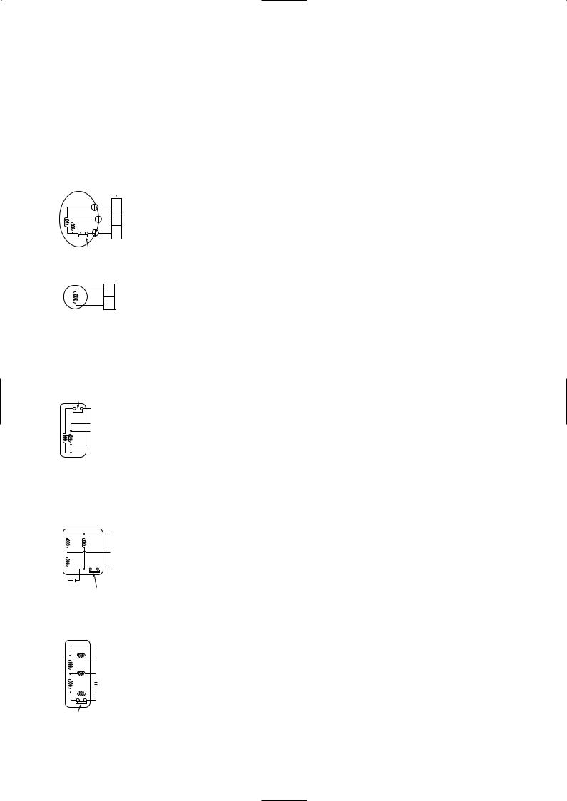
|
|
|
|
|
|
|
|
|
|
|
|
|
|
|
|
|
|
|
|
|
|
|
|
|
PLA-RP3AA |
|
|
PLA-RP4AA |
PLA-RP5AA |
|
|
|
PLA-RP6AA |
||||||||||||||||
PLA-RP3AA1 |
|
|
PLA-RP4AA1 |
PLA-RP5AA1 |
|
|
|
PLA-RP6AA1 |
||||||||||||||||
PLA-RP3AA.UK |
PLA-RP4AA.UK |
PLA-RP5AA.UK |
PLA-RP6AA.UK |
|||||||||||||||||||||
PLA-RP3AA1.UK PLA-RP4AA1.UK |
PLA-RP5AA1.UK PLA-RP6AA1.UK |
|||||||||||||||||||||||
|
Parts name |
|
|
|
|
|
|
|
|
Check points |
|
|
|
|
|
|
|
|||||||
|
|
|
|
|
|
|
|
|
|
|
|
|
|
|
|
|
|
|
|
|
|
|
||
Vane motor |
|
|
|
|
|
Measure the resistance between the terminals using a tester. |
|
|
|
|
|
|
|
|||||||||||
|
|
|
|
|
|
|
|
|
(Surrounding temperature20:) |
|
|
|
|
|
|
|
|
|
|
|
|
|||
|
|
|
|
|
|
|
|
|
|
Normal |
Abnormal |
|
|
|
|
|
|
|
|
|
|
|
||
|
|
|
|
|
|
|
|
|
|
|
|
|
|
|
|
|
|
|
|
|
|
|
|
|
|
|
|
|
|
|
|
|
|
|
15k" |
Open or short |
|
|
|
|
|
|
|
|
|
|
|
||
|
|
|
|
|
|
|
|
|
|
|
|
|
|
|
|
|
|
|
|
|
|
|||
Fan motor |
|
|
|
|
|
Measure the resistance between the terminals using a tester. |
|
|
|
|
|
|
|
|||||||||||
|
Relay connector |
|
(Winding temperature 20:) |
|
|
|
|
|
|
|
|
|
|
|
|
|||||||||
1 |
|
|
|
|
|
|
|
|
|
|
|
|
|
|
|
|
|
|||||||
Red |
1 |
|
|
|
Motor terminal |
|
|
Normal |
|
|
|
|
|
|
|
|||||||||
|
|
|
|
|
|
|
|
|
|
|
|
|
|
|
|
|||||||||
2 |
White |
2 |
|
|
|
or |
PLA-RP3AA |
|
|
PLA-RP4,5,6AA |
|
|
|
Abnormal |
|
|
||||||||
|
|
|
|
|
|
|
|
Relay connector |
|
|
|
|
|
|
|
|
|
|||||||
3 |
|
|
|
|
|
|
|
|
|
|
|
|
|
|
|
|
|
|
|
|
||||
Black |
3 |
|
|
|
|
|
|
|
|
|
|
|
|
|
|
|
|
|
|
|||||
|
|
Red-Black |
87.2" |
|
28.7" |
|
|
|
|
Open or short |
|
|
||||||||||||
|
|
|
|
|
|
|
|
|
|
|
|
|
|
|
|
|
||||||||
|
Protector |
|
|
|
|
|
White-Black |
104.1" |
|
41.6" |
|
|
|
|
|
|
||||||||
|
|
|
|
|
|
|
|
|
|
|
|
|
|
|
||||||||||
|
|
OPEN :130: |
|
|
|
|
|
|
|
|
|
|
|
|
|
|
|
|
|
|||||
|
|
CLOSE:80i20: |
|
|
|
|
|
|
|
|
|
|
|
|
|
|
|
|
|
|||||
Drain pump |
|
|
|
|
|
Measure the resistance between the terminals using a tester. |
|
|
|
|
|
|
|
|||||||||||
|
|
Red |
|
|
|
|
(Winding temperature 20:) |
|
|
|
|
|
|
|
|
|
|
|
|
|||||
|
|
|
|
1 |
|
|
|
|
|
Normal |
Abnormal |
|
|
|
|
|
|
|
|
|
|
|
||
|
|
|
|
2 |
|
|
|
|
|
290" |
Open or short |
|
|
|
|
|
|
|
|
|
|
|
||
|
|
Red |
|
|
|
|
|
|
|
|
|
|
|
|
|
|
|
|
|
|
|
|
||
|
|
|
|
|
|
|
|
|
|
|
|
|
|
|
|
|
|
|
|
|||||
|
|
|
|
|
|
|
|
|
|
|
|
|
|
|
|
|
|
|
|
|||||
PEA-RP3EA.TH-A PEA-RP4EA.TH-A PEA-RP5EA.TH-A PEA-RP6EA.TH-A |
||||||||||||||||||||||||
|
Parts name |
|
|
|
|
|
|
|
|
Check points |
|
|
|
|
|
|
|
|||||||
|
|
|
|
|
|
|
|
|
|
|
|
|
|
|
|
|
|
|
|
|||||
Fan motor (MF) |
|
|
|
|
Measure the resistance between the terminals using a tester. |
|
|
|
|
|
|
|
||||||||||||
Protector |
|
|
|
|
|
(Winding temperature 20:) |
|
|
|
|
|
|
|
|
|
|
|
|
||||||
(PEA-RP3,4,5EA) |
|
|
|
|
|
|
|
|
|
|
|
|
|
|
|
|
|
|
|
|
||||
OPEN :135: |
|
|
|
|
|
Motor terminal |
|
|
|
Normal |
|
|
|
|
|
|
|
|||||||
CLOSE:86i15: |
|
|
|
|
|
|
|
|
|
|
|
|
|
|
|
|
|
|
|
|||||
(PEA-RP6EA) |
|
|
|
|
|
or |
|
|
|
PEA- |
|
|
|
Abnormal |
|
|
||||||||
OPEN :150: |
|
|
|
|
Relay connector |
|
|
|
|
|
|
|
|
|
|
|
|
|
|
|||||
|
|
|
|
RP3EA.TH-A |
RP4EA.TH-A |
RP5EA.TH-A |
RP6EA.TH-A |
|
|
|
|
|||||||||||||
CLOSE:96i15: |
|
|
|
|
|
|
|
|
|
|
||||||||||||||
|
|
|
White |
|
|
|
|
|
White-Black |
28.6" |
|
20.6" |
|
15.3" |
|
10.2" |
|
|
|
|
||||
|
|
|
Orange |
|
|
|
|
|
Black-Blue |
12.5" |
|
8.1" |
|
|
5.1" |
|
5.2" |
Open or short |
|
|
|
|||
|
|
|
|
|
|
|
|
|
|
|
|
|
|
|
||||||||||
|
|
|
Red |
|
|
|
|
|
|
|
|
|
|
|
||||||||||
|
|
|
|
|
|
|
|
Blue-Brown |
4.3" |
|
3.2" |
|
|
2.7" |
|
3.1" |
|
|
|
|||||
|
|
|
Brown |
|
|
|
|
|
|
|
|
|
|
|
|
|||||||||
|
|
|
Blue |
|
|
|
|
|
Brown-Red |
23.6" |
|
16.0" |
|
|
14.5" |
|
12.1" |
|
|
|
|
|||
|
|
|
Black |
|
|
|
|
|
|
|
|
|
|
|
|
|
|
|
|
|
|
|
|
|
|
|
|
|
|
|
|
|
|
|
|
|
|
|
|||||||||||
PEAD-RP3EA.UK PEAD-RP4EA.UK PEAD-RP5EA.UK PEAD-RP6EA.UK |
||||||||||||||||||||||||
PEAD-RP3EA1.UK PEAD-RP4EA1.UK PEAD-RP5EA1.UK |
PEAD-RP6EA1.UK |
|||||||||||||||||||||||
|
Parts name |
|
|
|
|
|
|
|
|
Check points |
|
|
|
|
|
|
|
|||||||
|
|
|
|
|
|
|
|
|
|
|
|
|
|
|
|
|||||||||
Fan motor (MF) |
|
|
|
|
Measure the resistance between the terminals using a tester. |
|
|
|
|
|
|
|
||||||||||||
PEAD-RP3EA(1).UK |
|
|
(Winding temperature 20:) |
|
|
|
|
|
|
|
|
|
|
|
|
|||||||||
|
|
|
|
|
|
|
|
|
|
|
|
|
|
|
|
|
|
|||||||
|
|
|
Motor terminal |
Normal |
|
|
|
|
|
|
|
|
|
|
|
|
||||||||
|
|
|
|
|
Black |
|
|
|
|
|
|
|
|
|
|
|
|
|
|
|
||||
|
|
|
|
|
|
|
|
or |
|
|
|
|
|
Abnormal |
|
|
|
|
|
|
|
|||
|
|
|
|
|
|
|
|
|
|
|
|
|
|
|
|
|
|
|
|
|
|
|||
|
|
|
|
|
Blue |
|
|
Relay connector |
PEAD-RP3EA(1).UK |
|
|
|
|
|
|
|
|
|
|
|
||||
|
|
|
|
|
|
|
|
|
|
|
|
|
|
|
|
|
|
|
|
|
|
|
||
|
|
|
|
|
|
|
|
|
|
Gray-Black |
43.5" |
|
|
|
|
|
|
|
|
|
|
|
|
|
|
|
|
|
|
Gray |
|
|
(White or Red open) |
|
|
|
|
|
|
|
|
|
|
|
|
||||
|
|
|
|
|
|
|
|
|
|
|
|
|
|
|
|
|
|
|
|
|
|
|
||
|
|
|
|
|
|
|
|
|
|
|
|
|
|
|
|
|
|
|
|
|
|
|
||
Red White |
|
|
|
|
|
|
Black-Blue |
14.74" |
|
|
|
Open or short |
|
|
|
|
|
|
|
|||||
|
Protector |
|
|
|
|
(White or Red open) |
|
|
|
|
|
|
|
|
|
|
||||||||
|
OPEN :150: |
|
|
|
|
|
|
|
|
|
|
|
|
|
|
|
|
|||||||
|
CLOSE:96i15: |
|
|
|
Blue-Red |
57.5" |
|
|
|
|
|
|
|
|
|
|
|
|
||||||
|
|
|
|
|
|
|
|
|
|
|
|
|
|
|
|
|
|
|
|
|
|
|||
|
|
|
|
|
|
|
|
|
(White or Red open) |
|
|
|
|
|
|
|
|
|
|
|
|
|||
|
|
|
|
|
|
|
|
|
|
|
|
|
|
|
|
|
|
|
|
|
|
|
||
PEAD-RP4,5,6EA(1).UK |
|
|
|
|
|
|
|
|
|
|
|
|
|
|
|
|
|
|
||||||
|
|
|
|
|
|
|
|
|
|
|
|
|
|
|
|
|
|
|||||||
|
|
|
Motor terminal |
|
|
|
Normal |
|
|
|
|
|
|
|
||||||||||
|
|
|
|
|
|
|
|
|
|
|
|
|
|
|
|
|
|
|
|
|||||
|
|
|
|
|
|
|
|
|
|
|
|
|
|
|
|
|
|
|
|
|
|
|
|
|
|
|
|
|
Black |
|
|
|
|
|
or |
|
|
|
PEAD- |
|
|
|
Abnormal |
|
|
||||
|
|
|
|
Blue |
|
|
|
|
Relay connector |
|
|
|
|
|
|
|
|
|
|
|
|
|
|
|
|
|
|
|
|
|
|
|
RP4EA(1).UK |
|
|
RP5EA(1).UK RP6EA(1).UK |
|
|
|
|
|||||||||
|
|
|
|
|
|
|
|
|
|
|
|
|
|
|
|
|||||||||
|
|
|
|
|
|
|
|
|
|
|
|
|
|
|
|
|
|
|
|
|
|
|
|
|
|
|
|
|
|
|
|
|
|
|
Gray-Black |
24.76" |
|
|
|
10.27" |
|
|
|
|
|
|
|
||
|
|
|
|
Red |
|
|
|
|
(White or Red open) |
|
|
|
|
|
|
|
|
|
||||||
|
|
|
|
|
|
|
|
|
|
|
|
|
|
|
|
|
|
|
|
|
|
|||
|
|
|
|
White |
|
|
|
|
|
|
|
|
|
|
|
|
|
|
|
|
|
|
|
|
|
|
|
|
|
|
|
|
|
|
|
|
|
|
|
|
|
|
|
|
|
|
|
|
|
|
|
|
|
Gray |
|
|
|
|
|
Blue-Black |
4.78" |
|
|
2.11" |
|
|
|
|
|
|
|
|||
|
|
|
|
|
|
|
|
|
|
|
|
|
|
|
|
|
|
|
|
|
Open or short |
|
|
|
Protector |
|
|
|
|
|
|
Black-Red |
18.99" |
|
|
|
20.75" |
|
|
|
|
|
|
||||||
|
|
|
|
|
|
|
|
|
|
|
|
|
|
|
|
|||||||||
|
OPEN :135: |
|
|
|
|
(White or Red open) |
|
|
|
|
|
|
|
|
|
|||||||||
|
CLOSE:86i15: |
|
|
|
|
|
|
|
|
|
|
|
|
|
|
|
|
|
|
|||||
|
|
|
|
|
|
|
|
|
|
|
|
|
|
|
|
|
|
|
|
|
|
|
|
|
|
|
|
|
|
|
|
|
|
|
Gray-Red |
36.63" |
|
|
|
25.44" |
|
|
|
|
|
|
|
||
|
|
|
|
|
|
|
|
|
(White or Red open) |
|
|
|
|
|
|
|
|
|
||||||
|
|
|
|
|
|
|
|
|
|
|
|
|
|
|
|
|
|
|
|
|
|
|
||
|
|
|
|
|
|
|
|
|
|
|
|
|
|
|
|
|
|
|
|
|
|
|
|
|
|
|
|
|
|
|
|
|
|
|
|
|
|
|
|
|
|
|
|
|
|
|
|
|
|
19
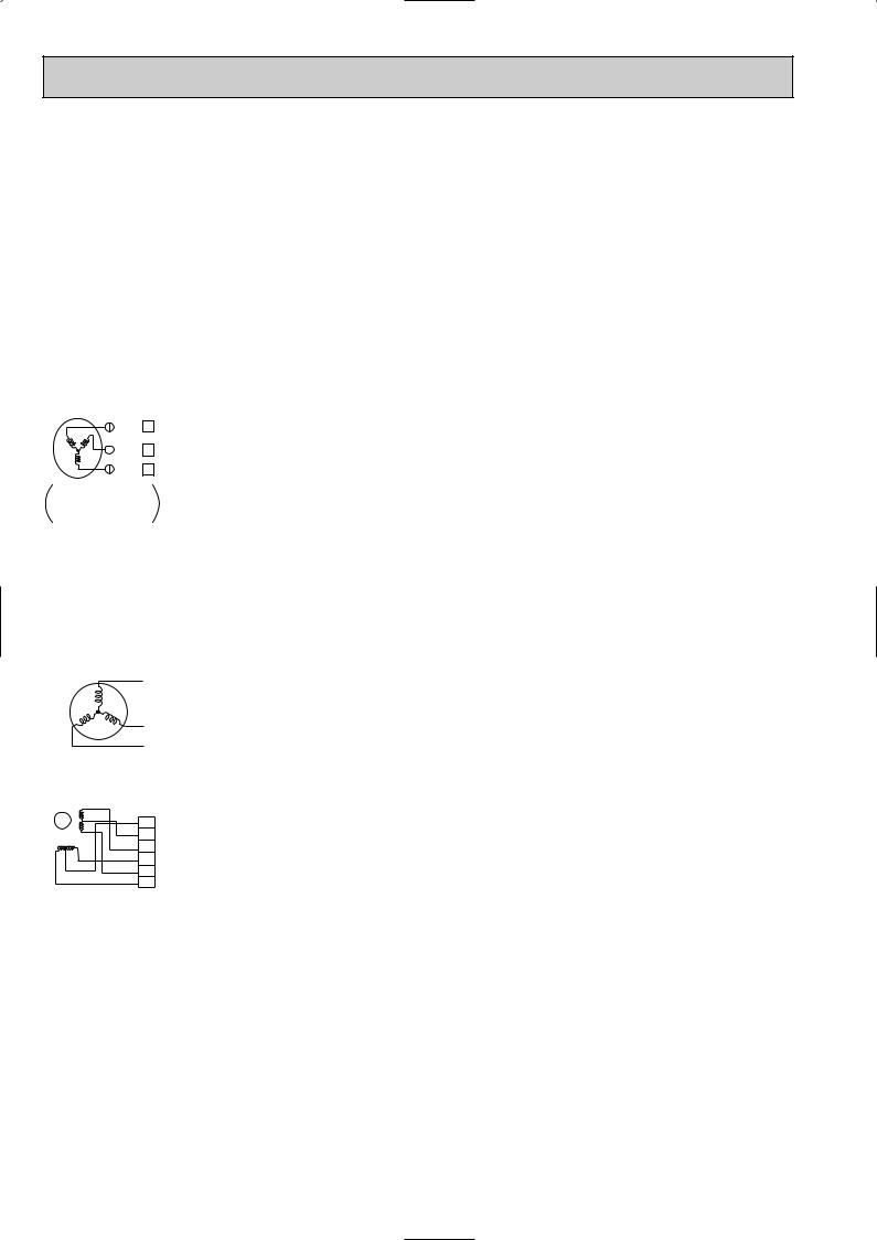
5-2. OUTDOOR UNIT
PUHZ-RP3VHA PUHZ-RP4VHA PUHZ-RP5VHA PUHZ-RP6VHA PUHZ-RP3VHA-A PUHZ-RP4VHA-A PUHZ-RP5VHA-A PUHZ-RP6VHA-A
Parts name |
|
|
|
|
|
|
|
|
|
|
|
Check points |
||||||||||
|
|
|
|
|
|
|
|
|
|
|
|
|
|
|
|
|
|
|
|
|
||
Thermistor (TH3) |
|
Disconnect the connector then measure the resistance using a tester. |
||||||||||||||||||||
|
(Surrounding temperature 10:~30:) |
|
|
|
|
|
|
|
|
|
||||||||||||
<Outdoor pipe> |
|
|
|
|
|
|
|
|
|
|
||||||||||||
Thermistor (TH4) |
|
|
|
|
|
|
|
Normal |
|
Abnormal |
|
|
|
|
|
|||||||
<Discharge> |
|
|
TH4 |
|
|
|
|
160k"~410k" |
|
|
|
|
|
|
|
|
|
|||||
|
|
|
|
|
|
|
|
|
|
|
|
|
|
|
|
|
|
|
||||
Thermistor (TH6) |
|
|
TH3 |
|
|
|
|
|
|
|
|
|
|
|
|
|
|
|
|
|||
<Outdoor 2-phase pipe> |
|
TH6 |
|
|
|
|
4.3k"~9.6k" |
|
Open or short |
|
|
|
|
|
||||||||
|
|
|
|
|
|
|
|
|
|
|
|
|
|
|
|
|||||||
Thermistor (TH7) |
|
|
TH7 |
|
|
|
|
|
|
|
|
|
|
|
|
|
|
|
|
|||
<Outdoor> |
|
|
|
|
|
|
|
|
|
|
|
|
|
|
|
|
|
|
|
|
||
|
|
|
TH8 |
|
|
|
|
39k"~105k" |
|
|
|
|
|
|
|
|
|
|||||
Thermistor (TH8) |
|
|
|
|
|
|
|
|
|
|
|
|
|
|
|
|||||||
|
|
|
|
|
|
|
|
|
|
|
|
|
|
|
|
|
|
|
||||
<Heat sink> |
|
|
|
|
|
|
|
|
|
|
|
|
|
|
|
|
|
|
|
|
||
|
|
|
|
|
|
|
|
|
|
|
|
|
|
|
|
|
||||||
Fan motor(MF1,MF2) |
Measure the resistance between the terminals using a tester. |
|||||||||||||||||||||
|
|
|
Red |
W |
(Winding temperature 20:) |
|
|
|
|
|
|
|
|
|
||||||||
|
|
|
|
|
|
|
|
|
|
|
|
|
|
|
|
|
|
|
|
|
||
|
|
|
White |
V |
|
Relay connector |
|
Normal |
|
Abnormal |
|
|
|
|
|
|||||||
|
|
|
|
|
|
|
|
|
|
|
|
|
|
|
|
|
|
|
|
|
||
|
|
|
Black |
|
Red — Black |
|
|
|
|
|
|
|
|
|
|
|
|
|
||||
|
|
|
U |
|
|
|
|
|
|
|
|
|
|
|
|
|
|
|||||
|
|
|
|
|
Black — White |
|
15.1±0.5" |
|
Open or short |
|
|
|
|
|
||||||||
Pin number of relay |
|
|
|
|
|
|
|
|
||||||||||||||
|
|
|
|
|
|
|
|
|
|
|
|
|
|
|
|
|
|
|||||
connector is different |
|
White — Red |
|
|
|
|
|
|
|
|
|
|
|
|
|
|||||||
from that motor |
|
|
|
|
|
|
|
|
|
|
|
|
|
|
|
|
|
|
|
|||
connector |
|
|
|
|
|
|
|
|
|
|
|
|
|
|
|
|
|
|
|
|
||
Solenoid valve coil |
Measure the resistance between the terminals using a tester. |
|||||||||||||||||||||
<Four-way valve> |
|
(Surrounding temperature 20:) |
|
|
|
|
|
|
|
|
|
|||||||||||
(21S4) |
|
|
|
|
|
|
|
|
|
|
|
|
|
|
|
|
|
|
|
|
||
|
|
|
|
|
|
|
|
|
|
Normal |
|
|
|
|
|
Abnormal |
|
|||||
|
|
|
|
|
|
|
|
|
|
|
|
|
|
|
|
|
|
|
||||
|
|
|
|
|
|
|
|
|
|
|
|
|
|
|
|
|
|
|
|
|
||
|
|
|
|
|
|
|
PUHZ-RP3VHA |
|
PUHZ-RP4, 5, 6VHA |
|
Open or short |
|
||||||||||
|
|
|
|
|
|
|
|
|
|
|
|
|
|
|
|
|
|
|
|
|
|
|
|
|
|
|
|
|
|
2350±170" |
|
|
|
|
1370±100" |
|
|
|
|||||||
|
|
|
|
|
|
|
|
|
|
|
|
|
|
|
|
|||||||
|
|
|
|
|
|
|
|
|
|
|
|
|
|
|
|
|
|
|
|
|
|
|
Motor for compressor |
Measure the resistance between the terminals using a tester. |
|||||||||||||||||||||
(MC) |
|
|
U |
|
(Winding temperature 20:) |
|
|
|
|
|
|
|
|
|
||||||||
|
|
|
|
|
|
|
|
|
|
|
|
Normal |
|
|
|
|
|
Abnormal |
|
|||
|
|
|
|
|
|
|
|
|
|
|
|
|
|
|
|
|
|
|
||||
|
|
|
|
|
|
|
|
|
|
|
|
|
|
|
|
|
|
|||||
|
|
|
|
|
|
|
PUHZ-RP3VHA |
|
PUHZ-RP4, 5, 6VHA |
|
Open or short |
|
||||||||||
|
|
|
V |
|
|
|
|
|
|
|
|
|
|
|
|
|
|
|
|
|
|
|
|
|
|
|
|
|
0.865"~0.895" |
|
|
|
0.266" |
|
|
|
|
||||||||
|
|
|
W |
|
|
|
|
|
|
|
|
|
|
|
||||||||
|
|
|
|
|
|
|
|
|
|
|
|
|
|
|
|
|
|
|
|
|
|
|
|
|
|
|
|
|
|
|
|
|
|
|
|
|
|
|
|
||||||
Linear expansion valve |
Disconnect the connector then measure the resistance using a tester. |
|||||||||||||||||||||
( LEV(A),LEV(B) ) |
(Winding temperature 20:) |
|
|
|
|
|
|
|
|
|
||||||||||||
|
|
|
|
|
|
Normal |
|
|
Abnormal |
|
|
|||||||||||
3 |
|
|
|
|
|
|
|
|
|
|
|
|
|
|||||||||
|
|
|
|
|
|
|
|
|
|
|
|
|
|
|
|
|
|
|
|
|
|
|
M 2 |
|
|
Red |
1 |
|
(1) - (6) |
|
(1) - (4) |
(2) - (5) |
(2) - (3) |
|
|
|
|
|
|
|
|||||
|
|
|
|
|
|
|
|
|
|
|
|
|||||||||||
5 |
|
|
Brown |
2 |
|
|
|
|
|
|
|
|
|
|||||||||
|
|
|
Red - White |
Red - Orange |
Brown - Yellow |
Brown - Blue |
Open or short |
|
|
|||||||||||||
1 |
4 |
|
Blue |
3 |
|
|
||||||||||||||||
6 |
|
|
|
|
|
|
|
|
|
|
|
|
|
|
|
|
|
|
|
|
||
|
|
|
Orange |
4 |
|
|
|
|
|
|
|
|
|
|
|
|
|
|
|
|
|
|
|
|
|
|
|
|
|
|
|
46±4" |
|
|
|
|
|
|
|
|
|
|
|||
|
|
|
Yellow |
5 |
|
|
|
|
|
|
|
|
|
|
|
|
|
|
|
|
||
|
|
|
White |
6 |
|
|
|
|
|
|
|
|
|
|
|
|
|
|
|
|
|
|
|
|
|
|
|
|
|
|
|
|
|
|
|
|
|
|
|
|
|
|
|
||
|
|
|
|
|
|
|
|
|
||||||||||||||
Solenoid valve coil |
Measure the resistance between the terminals using a tester. |
|||||||||||||||||||||
(Surrounding temperature 20:) |
|
|
|
|
|
|
|
|
|
|||||||||||||
<Bypass valve> |
|
|
|
|
|
|
|
|
|
|
||||||||||||
|
|
|
|
|
|
|
|
|
|
|
|
|
|
|
|
|
|
|
||||
(SV) |
|
|
|
|
|
|
Normal |
|
|
|
|
Abnormal |
|
|
|
|
|
|
|
|||
|
|
|
|
|
|
1197±10" |
|
|
|
Open or short |
|
|||||||||||
|
|
|
|
|
|
|
|
|
|
|
|
|
|
|
|
|
|
|
|
|
|
|
5-3. COMPRESSOR TECHNICAL DATA |
||||
|
|
|
(at 20°C) |
|
Unit |
PUHZ-RP3VHA |
PUHZ-RP4,5,6VHA |
||
|
|
|
||
Compressor model |
TNB220FMBH |
ANV33FDAMT |
||
|
|
|
|
|
Winding |
U-V |
0.865 ~ 0.895 |
0.266 |
|
|
|
|
||
U-W |
0.865 ~ 0.895 |
0.266 |
||
Resistance |
||||
( " ) |
|
|
|
|
W-V |
0.865 ~ 0.895 |
0.266 |
||
|
||||
|
|
|
|
|
20
HOW TO CHECK THE COMPONENTS
<Thermistor feature chart>
Low temperature thermistors
•Thermistor <Outdoor pipe> (TH3)
•Thermistor <Outdoor 2-phase pipe> (TH6)
•Thermistor <Outdoor> (TH7)
Thermistor R0 = 15k' ± 3%
B constant = 3480k' ± 2%
Rt =15exp{3480( |
1 |
– |
1 |
)} |
|
273+t |
273 |
||||
0: |
15k' |
30: |
4.3k' |
||
10: |
9.6k' |
40: |
3.0k' |
||
20: |
6.3k' |
|
|
|
|
25: |
5.2k' |
|
|
|
|
Medium temperature thermistor
• Thermistor <Heat sink> (TH8)
Thermistor R50 = 17k' ± 2%
B constant = 4150k' ± 3%
|
1 |
|
– |
1 |
|
|
Rt =17exp{4150( |
|
|
|
)} |
||
273+t |
323 |
|||||
0: |
180k' |
|
|
|
||
25: |
50k' |
|
|
|
||
50: |
17k' |
|
|
|
||
70: |
8k' |
|
|
|
||
90: |
4k' |
|
|
|
||
High temperature thermistor
• Thermistor <Discharge> (TH4)
Thermistor R120 = 7.465k' ± 2%
B constant = 4057k' ± 2%
|
|
1 |
|
– |
1 |
|
|
Rt =7.465exp{4057( |
|
|
|
)} |
|||
273+t |
393 |
||||||
20: |
250k' |
70: |
|
|
34k' |
||
30: |
160k' |
80: |
|
|
24k' |
||
40: |
104k' |
90: |
|
17.5k' |
|||
50: |
70k' |
100: 13.0k' |
|||||
60: |
48k' |
110: |
|
|
9.8k' |
||
|
50 |
|
40 |
(K") |
30 |
Resistance |
20 |
|
10
0
-20 -10 0 10 20 30 40 50 Temperature (:)
200
(K") |
150 |
|
|
|
|
|
|
|
|
|
|
|
|
|
|
|
|
|
|
|
|
|
|
|
|
|
|
|
|
|
|
|
|
|
|
|
|
|
|
|
|
|
|
|
|
|
|
|
|
|
|
|
|
|
|
|
|
|
|
|
|
|
|
|
|
|
|
|
|
|
|
|
|
|
|
|
|
|
|
|
|
|
|
|
|
|
|
|
|
|
|
|
|
|
|
|
|
|
|
|
|
||
|
|
|
|
|
|
|
|
|
|
|
|
|
|
|
|
|
|
|
|
|
|
|
|
|
|
|
|
|
|
|
|
|
|
|
|
|
|
|
|
|
|
|
|
|
|
|
|
|
|
|
|
|
|
|
|
|
|
|
|
|
|
|
|
|
|
|
|
|
|
|
|
|
|
|
|
|
|
|
|
|
|
|
|
|
|
|
|
|
|
|
|
|
|
|
|
|
|
|
|
|
|
|
|
|
|
|
|
|
|
|
|
|
|
|
|
|
|
|
|
|
|
|
|
|
|
|
|
|
|
|
|
|
|
|
|
|
|
|
|
|
|
|
|
|
|
|
|
|
|
|
|
|
|
|
|
Resistance |
100 |
|
|
|
|
|
|
|
|
|
|
|
|
|
|
|
|
|
|
|
|
|
|
|
|
|
|
|
|
|
|
|
|
|
|
|
|
|
|
|
|
|
|
|
|
|
|
|
|
|
|
|
|
|
|
|
|
|
|
|
|
|
|
|
|
|
|
|
|
|
|
|
|
|
|
|
|
|
|
|
|
|
|
|
|
|
|
|
|
|
|
|
|
|
|
|
|
|
|
|
|
||
|
|
|
|
|
|
|
|
|
|
|
|
|
|
|
|
|
|
|
|
|
|
|
|
|
|
|
|
|
|
|
|
|
|
|
|
|
|
|
|
|
|
|
|
|
|
|
|
|
|
||
|
|
|
|
|
|
|
|
|
|
|
|
|
|
|
|
|
|
|
|
|
|
|
|
|
|
|
|
|
|
|
|
|
|
|
|
|
|
|
|
|
|
|
|
|
|
|
|
|
|
||
50 |
|
|
|
|
|
|
|
|
|
|
|
|
|
|
|
|
|
|
|
|
|
|
|
|
|
|
|
|
|
|
|
|
|
|
|
|
|
|
|
|
|
|
|
|
|
|
|
|
|
|
|
|
|
|
|
|
|
|
|
|
|
|
|
|
|
|
|
|
|
|
|
|
|
|
|
|
|
|
|
|
|
|
|
|
|
|
|
|
|
|
|
|
|
|
|
|
|
|
|
|
|
||
|
|
|
|
|
|
|
|
|
|
|
|
|
|
|
|
|
|
|
|
|
|
|
|
|
|
|
|
|
|
|
|
|
|
|
|
|
|
|
|
|
|
|
|
|
|
|
|
|
|
||
|
|
|
|
|
|
|
|
|
|
|
|
|
|
|
|
|
|
|
|
|
|
|
|
|
|
|
|
|
|
|
|
|
|
|
|
|
|
|
|
|
|
|
|
|
|
|
|
|
|
|
|
|
|
|
|
|
|
|
|
|
|
|
|
|
|
|
|
|
|
|
|
|
|
|
|
|
|
|
|
|
|
|
|
|
|
|
|
|
|
|
|
|
|
|
|
|
|
|
|
|
|
|
|
|
|
|
|
|
|
|
|
|
|
|
|
|
|
|
|
|
|
|
|
|
|
|
|
|
|
|
|
|
|
|
|
|
|
|
|
|
|
|
|
|
|
|
|
|
|
|
|
|
|
|
|
|
|
|
|
|
|
|
|
|
|
|
|
|
|
|
|
|
|
|
|
|
|
|
|
|
|
|
|
|
|
|
|
|
|
|
|
|
|
|
|
|
|
|
|
|
|
|
|
|
|
|
|
|
0 |
|
|
|
|
|
|
|
|
|
|
|
|
|
|
|
|
|
|
|
|
|
|
|
|
|
|
|
|
|
|
|
|
|
|
|
|
|
|
|
|
|
|
|
|
|
|
|
|
|
|
|
|
|
|
|
|
|
|
|
|
|
|
|
|
|
|
|
|
|
|
|
|
|
|
|
|
|
|
|
|
|
|
|
|
|
|
|
|
|
|
|
|
|
|
|
|
|
|
|
|
|
|
|
|
|
|
|
|
|
|
|
|
|
|
|
|
|
|
|
|
|
|
|
|
|
|
|
|
|
|
|
|
|
|
|
|
|
|
|
|
|
|
|
|
|
|
|
|
|
|
|
|
|
|
|
|
|
|
|
|
|
|
|
|
|
|
|
|
|
|
|
|
|
|
|
|
|
|
|
|
|
|
|
|
|
|
|
|
|
|
|
|
|
|
|
|
|
|
|
|
|
|
|
|
|
|
|
|
|
|
|
|
|
|
|
|
|
|
|
|
|
|
|
|
|
|
|
|
|
|
|
|
|
|
|
|
|
|
|
|
|
|
|
|
|
|
|
|
|
|
|
|
|
|
|
|
|
|
|
|
|
|
|
|
|
|
|
|
|
|
50 |
75 |
|
|
100 |
|
|
125 |
|
|||||||||||||||||||||||||||||||
|
25 |
|
|
|
|
|
|||||||||||||||||||||||||||||||||||||||||||||
|
|
|
|
|
|
|
|
|
|
|
|
|
|
|
|
Temperature (:) |
|
|
|
|
|
|
|
|
|||||||||||||||||||||||||||
|
500 |
|
|
|
|
|
|
|
|
|
|
|
|
|
|
|
|
|
|
|
|
|
|
|
|
|
|
|
|
|
|
|
|
|
|
|
|
|
|
|
|
|
|
|
|
|
|
|
|
|
|
|
|
|
|
|
|
|
|
|
|
|
|
|
|
|
|
|
|
|
|
|
|
|
|
|
|
|
|
|
|
|
|
|
|
|
|
|
|
|
|
|
|
|
|
|
|
|
|
|
|
||
) |
400 |
|
|
|
|
|
|
|
|
|
|
|
|
|
|
|
|
|
|
|
|
|
|
|
|
|
|
|
|
|
|
|
|
|
|
|
|
|
|
|
|
|
|
|
|
|
|
|
|
|
|
|
|
|
|
|
|
|
|
|
|
|
|
|
|
|
|
|
|
|
|
|
|
|
|
|
|
|
|
|
|
|
|
|
|
|
|
|
|
|
|
|
|
|
|
|
|
|
|
|
|||
|
|
|
|
|
|
|
|
|
|
|
|
|
|
|
|
|
|
|
|
|
|
|
|
|
|
|
|
|
|
|
|
|
|
|
|
|
|
|
|
|
|
|
|
|
|
|
|
|
|||
|
|
|
|
|
|
|
|
|
|
|
|
|
|
|
|
|
|
|
|
|
|
|
|
|
|
|
|
|
|
|
|
|
|
|
|
|
|
|
|
|
|
|
|
|
|
|
|
|
|||
|
|
|
|
|
|
|
|
|
|
|
|
|
|
|
|
|
|
|
|
|
|
|
|
|
|
|
|
|
|
|
|
|
|
|
|
|
|
|
|
|
|
|
|
|
|
|
|
|
|||
|
|
|
|
|
|
|
|
|
|
|
|
|
|
|
|
|
|
|
|
|
|
|
|
|
|
|
|
|
|
|
|
|
|
|
|
|
|
|
|
|
|
|
|
|
|
|
|
|
|||
|
|
|
|
|
|
|
|
|
|
|
|
|
|
|
|
|
|
|
|
|
|
|
|
|
|
|
|
|
|
|
|
|
|
|
|
|
|
|
|
|
|
|
|
|
|
|
|
|
|||
|
|
|
|
|
|
|
|
|
|
|
|
|
|
|
|
|
|
|
|
|
|
|
|
|
|
|
|
|
|
|
|
|
|
|
|
|
|
|
|
|
|
|
|
|
|
|
|
|
|||
|
|
|
|
|
|
|
|
|
|
|
|
|
|
|
|
|
|
|
|
|
|
|
|
|
|
|
|
|
|
|
|
|
|
|
|
|
|
|
|
|
|
|
|
|
|
|
|
|
|||
|
|
|
|
|
|
|
|
|
|
|
|
|
|
|
|
|
|
|
|
|
|
|
|
|
|
|
|
|
|
|
|
|
|
|
|
|
|
|
|
|
|
|
|
|
|
|
|
|
|||
|
|
|
|
|
|
|
|
|
|
|
|
|
|
|
|
|
|
|
|
|
|
|
|
|
|
|
|
|
|
|
|
|
|
|
|
|
|
|
|
|
|
|
|
|
|
|
|
|
|
|
|
|
|
|
|
|
|
|
|
|
|
|
|
|
|
|
|
|
|
|
|
|
|
|
|
|
|
|
|
|
|
|
|
|
|
|
|
|
|
|
|
|
|
|
|
|
|
|
|
|
|
|
|
|
|
|
|
|
|
|
|
|
|
|
|
|
|
|
|
|
|
|
|
|
|
|
|
|
|
|
|
|
|
|
|
|
|
|
|
|
|
|
|
|
|
|
|
|
|
|
|
|
|
|
|
|
|
|
|
|
|
|
|
|
|
|
|
|
|
|
|
|
|
|
|
|
|
|
|
|
|
|
|
|
|
|
|
|
|
|
|
|
|
|
|
|
|
|
|
|
|
|
|
|
|
|
|
|
|
|
|
|
|
|
|
|
|
|
|
|
|
|
|
|
|
|
|
|
|
|
|
|
|
|
|
|
|
|
|
|
|
|
|
|
|
|
|
|
|
|
|
|
|
|
|
|
|
|
|
|
|
|
|
|
|
|
|
|
|
|
|
|
|
|
|
|
|
|
|
|
|
|
|
|
|
|
|
|
|
|
|
|
|
|
|
|
|
|
|
|
|
|
|
|
|
|
|
|
|
|
|
|
|
|
|
|
|
|
|
|
|
|
|
|
|
|
|
|
|
|
|
|
|
|
|
|
|
|
|
|
|
|
|
|
|
|
|
|
|
|
|
|
|
|
|
|
|
|
|
|
|
|
|
(K" |
300 |
|
|
|
|
|
|
|
|
|
|
|
|
|
|
|
|
|
|
|
|
|
|
|
|
|
|
|
|
|
|
|
|
|
|
|
|
|
|
|
|
|
|
|
|
|
|
|
|
|
|
|
|
|
|
|
|
|
|
|
|
|
|
|
|
|
|
|
|
|
|
|
|
|
|
|
|
|
|
|
|
|
|
|
|
|
|
|
|
|
|
|
|
|
|
|
|
|
|
|
|||
|
|
|
|
|
|
|
|
|
|
|
|
|
|
|
|
|
|
|
|
|
|
|
|
|
|
|
|
|
|
|
|
|
|
|
|
|
|
|
|
|
|
|
|
|
|
|
|
|
|||
|
|
|
|
|
|
|
|
|
|
|
|
|
|
|
|
|
|
|
|
|
|
|
|
|
|
|
|
|
|
|
|
|
|
|
|
|
|
|
|
|
|
|
|
|
|
|
|
|
|
|
|
Resistance |
200 |
|
|
|
|
|
|
|
|
|
|
|
|
|
|
|
|
|
|
|
|
|
|
|
|
|
|
|
|
|
|
|
|
|
|
|
|
|
|
|
|
|
|
|
|
|
|
|
|
|
|
|
|
|
|
|
|
|
|
|
|
|
|
|
|
|
|
|
|
|
|
|
|
|
|
|
|
|
|
|
|
|
|
|
|
|
|
|
|
|
|
|
|
|
|
|
|
|
|
|
|||
|
|
|
|
|
|
|
|
|
|
|
|
|
|
|
|
|
|
|
|
|
|
|
|
|
|
|
|
|
|
|
|
|
|
|
|
|
|
|
|
|
|
|
|
|
|
|
|
|
|||
|
|
|
|
|
|
|
|
|
|
|
|
|
|
|
|
|
|
|
|
|
|
|
|
|
|
|
|
|
|
|
|
|
|
|
|
|
|
|
|
|
|
|
|
|
|
|
|
|
|||
|
|
|
|
|
|
|
|
|
|
|
|
|
|
|
|
|
|
|
|
|
|
|
|
|
|
|
|
|
|
|
|
|
|
|
|
|
|
|
|
|
|
|
|
|
|
|
|
|
|||
|
|
|
|
|
|
|
|
|
|
|
|
|
|
|
|
|
|
|
|
|
|
|
|
|
|
|
|
|
|
|
|
|
|
|
|
|
|
|
|
|
|
|
|
|
|
|
|
|
|||
|
|
|
|
|
|
|
|
|
|
|
|
|
|
|
|
|
|
|
|
|
|
|
|
|
|
|
|
|
|
|
|
|
|
|
|
|
|
|
|
|
|
|
|
|
|
|
|
|
|||
|
|
|
|
|
|
|
|
|
|
|
|
|
|
|
|
|
|
|
|
|
|
|
|
|
|
|
|
|
|
|
|
|
|
|
|
|
|
|
|
|
|
|
|
|
|
|
|
|
|||
|
|
|
|
|
|
|
|
|
|
|
|
|
|
|
|
|
|
|
|
|
|
|
|
|
|
|
|
|
|
|
|
|
|
|
|
|
|
|
|
|
|
|
|
|
|
|
|
|
|||
100 |
|
|
|
|
|
|
|
|
|
|
|
|
|
|
|
|
|
|
|
|
|
|
|
|
|
|
|
|
|
|
|
|
|
|
|
|
|
|
|
|
|
|
|
|
|
|
|
|
|
||
|
|
|
|
|
|
|
|
|
|
|
|
|
|
|
|
|
|
|
|
|
|
|
|
|
|
|
|
|
|
|
|
|
|
|
|
|
|
|
|
|
|
|
|
|
|
|
|
|
|
||
|
|
|
|
|
|
|
|
|
|
|
|
|
|
|
|
|
|
|
|
|
|
|
|
|
|
|
|
|
|
|
|
|
|
|
|
|
|
|
|
|
|
|
|
|
|
|
|
|
|
||
|
|
|
|
|
|
|
|
|
|
|
|
|
|
|
|
|
|
|
|
|
|
|
|
|
|
|
|
|
|
|
|
|
|
|
|
|
|
|
|
|
|
|
|
|
|
|
|
|
|
||
|
|
|
|
|
|
|
|
|
|
|
|
|
|
|
|
|
|
|
|
|
|
|
|
|
|
|
|
|
|
|
|
|
|
|
|
|
|
|
|
|
|
|
|
|
|
|
|
|
|
||
|
|
|
|
|
|
|
|
|
|
|
|
|
|
|
|
|
|
|
|
|
|
|
|
|
|
|
|
|
|
|
|
|
|
|
|
|
|
|
|
|
|
|
|
|
|
|
|
|
|
||
|
|
|
|
|
|
|
|
|
|
|
|
|
|
|
|
|
|
|
|
|
|
|
|
|
|
|
|
|
|
|
|
|
|
|
|
|
|
|
|
|
|
|
|
|
|
|
|
|
|
||
|
|
|
|
|
|
|
|
|
|
|
|
|
|
|
|
|
|
|
|
|
|
|
|
|
|
|
|
|
|
|
|
|
|
|
|
|
|
|
|
|
|
|
|
|
|
|
|
|
|
||
|
|
|
|
|
|
|
|
|
|
|
|
|
|
|
|
|
|
|
|
|
|
|
|
|
|
|
|
|
|
|
|
|
|
|
|
|
|
|
|
|
|
|
|
|
|
|
|
|
|
||
|
|
|
|
|
|
|
|
|
|
|
|
|
|
|
|
|
|
|
|
|
|
|
|
|
|
|
|
|
|
|
|
|
|
|
|
|
|
|
|
|
|
|
|
|
|
|
|
|
|
||
|
0 |
|
|
|
|
|
|
|
|
|
|
|
|
|
|
|
|
|
|
|
|
|
|
|
|
|
|
|
|
|
|
|
|
|
|
|
|
|
|
|
|
|
|
|
|
|
|
|
|
|
|
|
|
|
|
|
|
|
|
|
|
|
|
|
|
|
|
|
|
|
|
|
|
|
|
|
|
|
|
|
|
|
|
|
|
|
|
|
|
|
|
|
|
|
|
|
|
|
|
|
|
||
|
|
|
|
|
|
|
|
|
|
|
|
|
|
|
|
|
|
|
|
|
|
|
|
|
|
|
|
|
|
|
|
|
|
|
|
|
|
|
|
|
|
|
|
|
|
|
|
|
|
||
|
|
|
|
|
|
|
|
|
|
|
|
|
|
|
|
|
|
|
|
|
|
|
|
|
|
|
|
|
|
|
|
|
|
|
|
|
|
|
|
|
|
|
|
|
|
|
|
|
|
||
|
|
|
|
|
|
|
|
|
|
|
|
|
|
|
|
|
|
|
|
|
|
|
|
|
|
|
|
|
|
|
|
|
|
|
|
|
|
|
|
|
|
|
|
|
|
|
|
|
|
||
|
|
|
|
|
|
|
|
|
|
|
|
|
|
|
|
|
|
|
|
|
|
|
|
|
|
|
|
|
|
|
|
|
|
|
|
|
|
|
|
|
|
|
|
|
|
|
|
|
|
||
|
|
|
|
|
|
|
|
|
|
|
|
|
|
|
|
|
|
|
|
|
|
|
|
|
|
|
|
|
|
|
|
|
|
|
|
|
|
|
|
|
|
|
|
|
|
|
|
|
|
||
|
|
|
|
|
|
|
|
|
|
|
|
|
|
|
|
|
|
|
|
|
|
|
|
|
|
|
|
|
|
|
|
|
|
|
|
|
|
|
|
|
|
|
|
|
|
|
|
|
|
||
|
|
|
|
|
|
|
|
|
|
|
|
|
|
|
|
|
|
|
|
|
|
|
|
|
|
|
|
|
|
|
|
|
|
|
|
|
|
|
|
|
|
|
|
|
|
|
|
|
|
||
|
|
|
|
|
|
|
|
|
|
|
|
|
|
|
|
|
|
|
|
|
|
|
|
|
|
|
|
|
|
|
|
|
|
|
|
|
|
|
|
|
|
|
|
|
|
|
|
|
|
||
25 |
50 |
75 |
100 |
120 |
Temperature (:)
21

Linear expansion valve
(1) Operation summary of the linear expansion valve.
•Linear expansion valve open/close through stepping motor after receiving the pulse signal from the outdoor controller board.
•Valve position can be changed in proportion to the number of pulse signal.
<Connection between the outdoor controller board and the linear expansion valve>
Outdoor controller board
DC12V
LEV |
Red |
1 |
|
3 |
M |
2 |
1 |
5 |
6 |
4 |
Drive circuit
|
Brown |
2 |
|
[4 |
Blue |
3 |
[4 |
|
|||
[3 |
Orange |
4 |
[3 |
|
|||
[2 |
Yellow |
5 |
[2 |
|
|||
[1 |
White |
6 |
[1 |
|
|||
Connector LEV-A |
|
|
|
|
LEV-B |
|
|
<Output pulse signal and the valve operation>
Output |
|
|
|
Output |
|
|
|
|
|
|
|
|
|
|
|
|
|
(Phase) |
1 |
2 |
3 |
4 |
5 |
6 |
7 |
8 |
|
||||||||
|
|
|
|
|
|
|
|
|
[1 |
ON |
ON |
OFF |
OFF |
OFF |
OFF |
OFF |
ON |
|
|
|
|
|
|
|
|
|
[2 |
OFF |
ON |
ON |
ON |
OFF |
OFF |
OFF |
OFF |
|
|
|
|
|
|
|
|
|
[3 |
OFF |
OFF |
OFF |
ON |
ON |
ON |
OFF |
OFF |
|
|
|
|
|
|
|
|
|
[4 |
OFF |
OFF |
OFF |
OFF |
OFF |
ON |
ON |
ON |
|
|
|
|
|
|
|
|
|
(2) Linear expansion valve operation
Opening a valve : 8 → 7 → 6 → 5 → 4 → 3 → 2 → 1 → 8 Closing a valve : 1 → 2 → 3 → 4 → 5 → 6 → 7 → 8 → 1
The output pulse shifts in above order.
1. When linear expansion valve operation stops, all output phase become OFF.
When the switch is turned on, 700 pulse closing valve signal will be sent till it goes to A point in order to define the valve position. (The pulse signal is being sent for about 20 seconds.)
Valve position (capacity)
|
|
When the valve moves smoothly, there is no noise or vibration |
|
C |
occurring from the linear expansion valve : however, when the |
|
pulse number moves from B to A or when the valve is locked, |
|
|
|
|
|
|
more noise can be heard than normal situation. |
|
|
No noise is heard when the pulse number moves from B to A in |
|
|
case coil is burn out or motor is locked by open-phase. |
|
|
Noise can be detected by placing the ear against the screw dri- |
|
|
ver handle while putting the screw driver to the linear expansion |
Close |
Open |
valve. |
|
|
500 pulse
A Opening a valve all the way
B |
Pulse number |
Extra tightning (about 32 pulse)
22
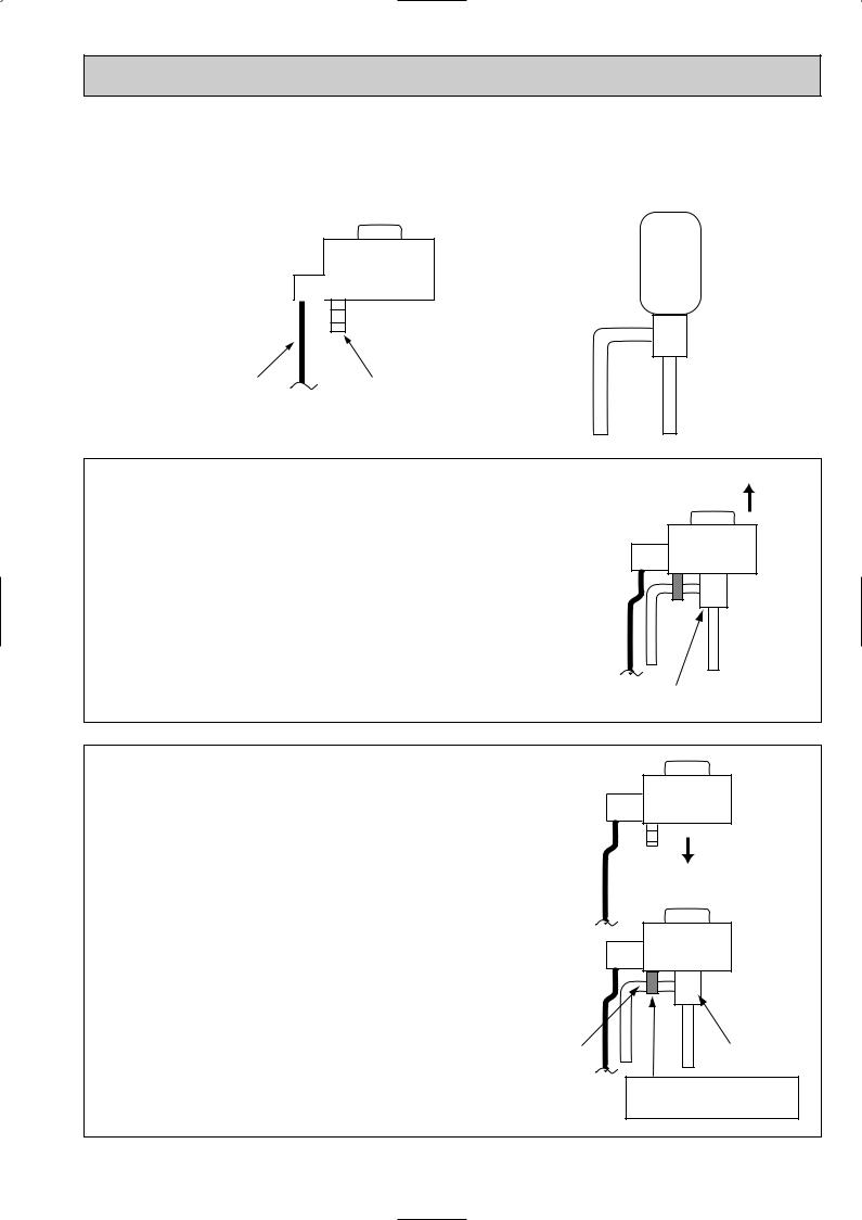
(3) How to attach and detach the coil of linear expansion valve
<Composition>
Linear expansion valve is separable into the main body and the coil as shown in the diagram below.
Coil |
Main body |
|
Lead wire |
Stopper |
<How to detach the coil>
Hold the lower part of the main body (shown as A) firmly so that the main body does not move and detach the coil by pulling it upward.
Be sure to detach the coil holding main body firmly. Otherwise pipes can bend due to pressure.
A
<How to attach the coil>
Hold the lower part of the main body (shown as A) firmly so that the main body does not move and attach the coil by inserting it downward into the main body. Then securely attach the coil stopper to pipe B. (At this time, be careful that stress is not added to lead wire and main body is not wound by lead wire.) If the stopper is not firmly attached to pipe B, coil may be detached from the main body and that can cause defective operation of linear expansion valve.
To prevent piping stress, be sure to attach the coil holding the main body of linear expansion valve firmly. Otherwise pipe may break.
B
A
Be sure to attach the stopper to pipe B.
23
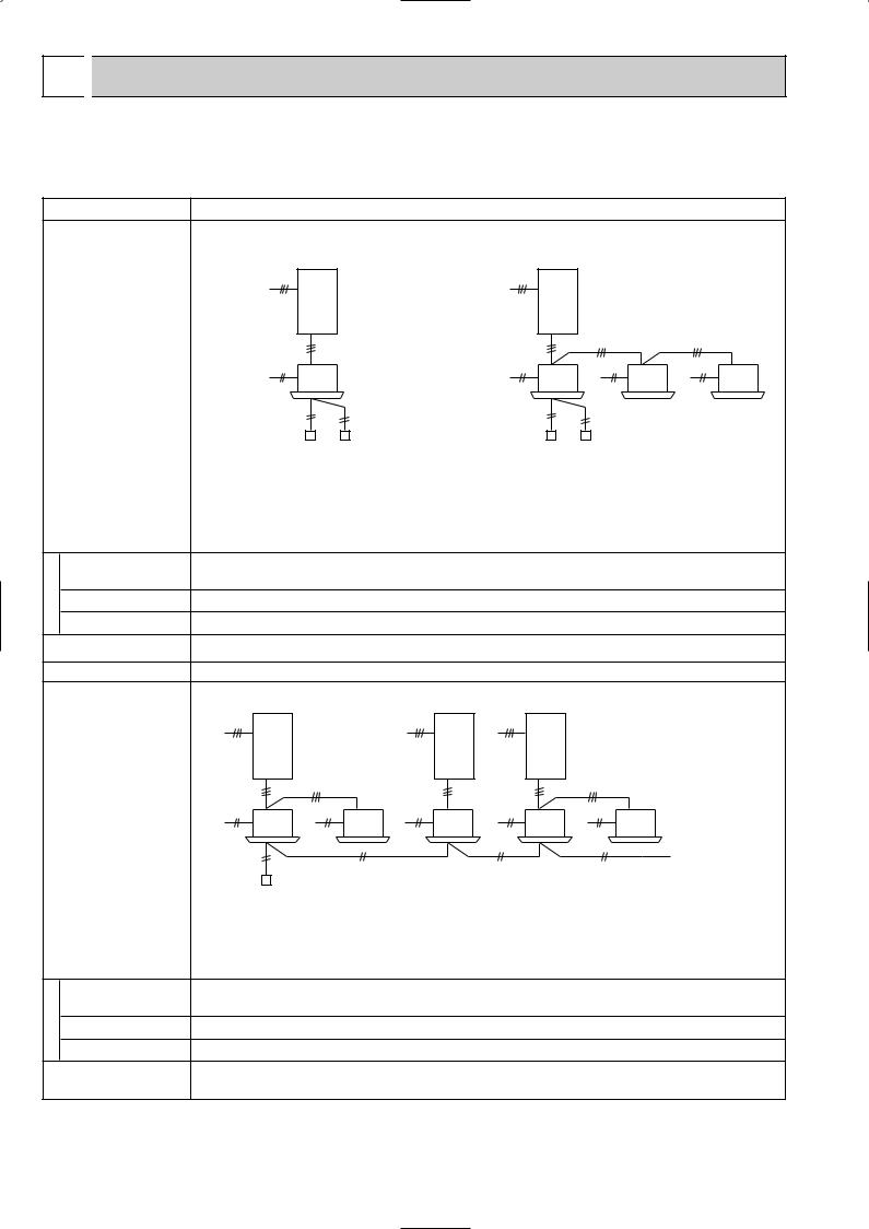
6 
 MICROPROCESSOR CONTROL
6-1. System construction
(1) System construction
A-control model which just wires the connecting line between the indoor and outdoor unit and supply the power is applicable to any models of standard (1:1), twin and triple. (Refer to 2 Start-up system.)
System construction
setting |
Remote controller |
Various |
Outdoor unit |
|
Indoor unit |
|
Remarks |
System construction
setting |
Remote controller |
Various |
Outdoor unit |
|
Indoor unit |
|
Remarks |
|
Standard 1:1 |
|
|
|
Synchronized twin. Triple |
|
||||||||
|
|
|
|
|
|
|
|
Outdoor unit; (00)...Refrigerant address |
||||||
|
|
|
|
|
|
|
|
|
|
|
|
|
(SW1; 3~6) |
|
|
|
|
|
|
|
|
|
Indoor unit; (00)–w |
|
|||||
|
|
|
|
|
|
(00) |
|
|
|
|
|
|
Indoor unit number |
|
|
|
|
|
|
|
|
|
|
|
|
||||
|
1 |
|
|
|
1 |
|
|
|
|
|
|
(auto setting) |
||
|
|
|
|
|
|
|
|
|
|
|
Refrigerant address |
|||
|
|
|
|
|
|
|
|
|
|
|
|
|
||
|
|
|
|
|
|
|
|
|
|
|
|
|
||
|
|
|
|
|
|
|
|
|
|
|
|
|
(receiving from the |
|
|
|
|
|
|
|
|
|
|
|
|
|
|
outdoor unit) |
|
|
2 |
|
|
|
2 |
|
|
2 |
|
2 |
|
|||
|
|
|
|
|
|
|
|
|
|
|
|
|
||
|
4 |
|
|
|
4 |
(00)-1 |
4 |
(00)-2 |
4 |
(00)-3 |
||||
|
3 |
|
|
|
|
3 |
|
|
|
|
|
|
|
|
|
Main |
Sub |
|
|
|
Main |
Sub |
|
|
|
|
|
|
|
1Unit (indoor/outdoor) power supply L/N |
|
|
1Unit (indoor/outdoor) power supply L/N |
|||||||||||
2Connecting line between the indoor and |
|
2Connecting line between the indoor and |
||||||||||||
outdoor; S1/S2/S3, Polarized 3-wire |
|
|
outdoor; S1/S2/S3, Polarized 3-wire |
|
||||||||||
3Remote controller transmission line; Non |
|
3Remote controller transmission line; Non |
||||||||||||
polarezed 2-wire |
|
|
|
polarezed 2-wire |
|
|
|
|
|
|
||||
4Auxiliary heater exclusive power supply; L/N |
|
4Auxiliary heater exclusive power supply; L/N |
||||||||||||
Remote control main/sub setting necessity |
|
Remote control main/sub setting necessity |
||||||||||||
(In case of 2 remote controllers) |
|
|
(In case of 2 remote controllers) |
|
||||||||||
No setting |
|
|
|
|
No setting (initial setting) |
|
|
|
|
|||||
No setting |
|
|
|
|
No setting (initial setting) |
|
|
|
|
|||||
|
|
|
|
|
(1) Indoor unit number is set automatically |
|||||||||
|
|
|
|
|
|
|
|
|
|
|
|
|
|
|
|
|
|
Group control |
|
|
|
|
|
|
|
|
|
||
|
|
|
|
|
|
|
|
Outdoor unit; (00)...Refrigerant address |
||||||
|
|
|
|
|
|
|
|
|
|
|
|
|
(SW1; 3~6) |
|
|
(00) |
|
(01) |
|
|
(02) |
|
Indoor unit; (00)–w |
|
|||||
1 |
1 |
1 |
|
|
|
|
|
|
Indoor unit number |
|||||
|
|
|
|
|
|
|
|
|||||||
|
|
|
|
|
|
|
|
|
|
|
|
|
(auto setting) |
|
|
|
|
|
|
|
|
|
|
|
|
|
|
Refrigerant address |
|
|
|
|
|
|
|
|
|
|
|
|
|
|
||
|
2 |
2 |
2 |
|
|
2 |
|
2 |
|
|
|
|
(receiving from the |
|
|
|
|
|
|
|
|
|
outdoor unit) |
||||||
|
|
|
|
|
|
|
|
|
||||||
|
|
|
|
|
|
|
|
|
|
|
|
|
||
4 |
(00)-1 4 |
(00)-2 4 |
(01)-1 |
4 |
(02)-1 |
4 |
|
(02)-2 |
|
|
|
|
|
|
3 |
3 |
|
3 |
|
|
|
3 |
|
|
|
|
|
||
|
|
|
|
|
|
|
|
|
|
|
||||
Main
1Unit (indoor/outdoor) power supply L/N
2Connecting line between the indoor and outdoor; S1/S2/S3, Polarized 3-wire 3Remote controller transmission line; Non polarezed 2-wire
4Auxiliary heater exclusive power supply; L/N
Remote control main/sub setting necessity (In case of 2 remote controllers)
No setting (initial setting)
Refrigerant address setting; SW1; 3~6
(1)Indoor unit number is set automatically
(2)When the refrigerant address of the unit is "00", Remote controller is supplied.
24
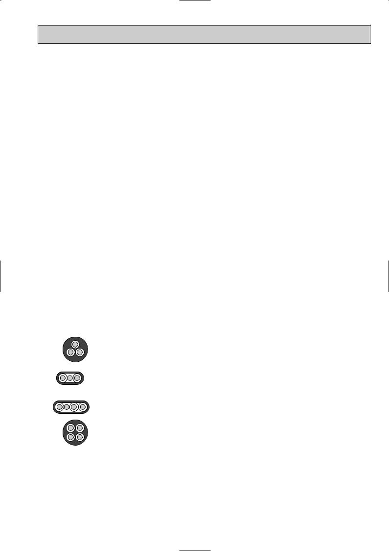
(2) The transmitting specification for “A” control
1Wiring regulations
Section |
Communications from remote controllers |
Communications between indoor and outdoor units |
|
|
|
The maximum length of |
500m |
80m (Including the wiring among indoor units |
total wiring |
|
in addition to the wiring between indoor and |
|
|
outdoor units) |
|
|
|
The maximum numbers |
One remote controller can connect and operate |
One outdoor unit can connect up to three |
for connection |
up to 16 indoor units by grouping them. 1 |
indoor units. |
|
One group can connect up to two remote controllers. |
|
|
1 Remote controller considers multiplex units as |
|
|
a single group. |
|
|
|
|
The cables applicable |
0.3mm2 to 1.25mm2 |
Use either flat-type cable (3 cores: {1.6mm or |
|
|
more) or wires in the table below. |
|
|
2 The diameter of the cables depends on |
|
|
each unit. |
Others |
The wirings as follows are not allowed: |
The core wire connected to terminal S2 shall be |
|
• The wiring that the indoor units of the same |
placed at the center of flat-type cable. |
|
refrigerant system are connected through TB5. |
|
|
• The wiring which directly connects the terminals |
|
|
for remote controllers. |
|
|
|
|
2Transmitting specification
Section |
|
Communications from remote controllers |
Communications between indoor and outdoor units |
||||
|
|
|
|
|
|
||
Transmitting speed |
|
83.3 bit/sec. (1 bit = 12ms) |
|
83.3 bit/sec. (1 bit = 12ms) |
|
||
|
|
|
|
||||
Normal transmission |
|
The terminal for remote controller transmits sig- |
Outdoor unit transmits signals every 3 seconds; |
||||
|
|
|
nals every 7.5 seconds; the indoor unit whose |
all the connected indoor units respond them. |
|||
|
|
|
refrigerant address is “0” responds them. |
|
|
||
|
|
|
|
|
|||
Modulation |
|
The waveform modulates at 50kHz. |
There is no modulation. |
|
|||
|
|
|
|
||||
Detection of abnormal |
|
When transmitting error is detected for three con- |
When transmitting error is detected for three |
||||
communication |
|
secutive minutes. |
|
consecutive minute. |
|
||
|
|
|
|
|
|||
WIRING SPECIFICATIONS FOR 220~240V 50Hz |
|
|
|
||||
(INDOOR-OUTDOOR CONNECTING CABLE) |
|
|
|
||||
|
|
|
|
|
|
|
|
Cross section |
|
Wire size |
Number |
|
Polarity |
L(m) |
|
of cable |
|
|
(mm2) |
of wires |
|
6 |
|
Round |
|
2.5 |
3 |
Clockwise : S1-S2-S3 |
(50) |
||
|
|
||||||
|
|
w Pay attention to stripe of yellow and green |
2 |
||||
|
|
|
|
|
|||
|
|
|
|
|
|
|
|
Flat |
|
|
|
|
Not applicable |
|
Not |
|
|
2.5 |
3 |
|
applicable |
||
|
|
(Because center wire has no cover finish) |
|||||
|
|
|
|
|
5 |
||
|
|
|
|
|
|
|
|
|
|
|
|
|
|
|
|
Flat |
|
|
|
|
|
|
(45) |
|
|
1.5 |
4 |
From left to right : S1-Open-S2-S3 |
|||
|
|
3 |
|||||
|
|
|
|
|
|
|
|
|
|
|
|
|
|
|
|
Round |
|
2.5 |
4 |
Clockwise : S1-S2-S3-Open |
60 |
||
|
|
||||||
|
|
w Connect S1 and S3 to the opposite angle |
4 |
||||
|
|
|
|
|
|||
|
|
|
|
|
|
|
|
1 : Power supply cords of appliances shall not be lighter than design 245 IEC or 227 IEC.2 : In case that cable with stripe of yellow and green is available.
3 : In case of regular polarity connection (S1-S2-S3), wire size is 1.5mm2.4 : In case of regular polarity connection (S1-S2-S3).
5 : In the flat cables are connected as this picture, they can be used up to 80m.


 (3C Flat cable 2)
S1 S2 S3
6 : Mentioned cable length is just a reference value.
It may be different depending on the condition of installation, Humidity or materials, etc.
25
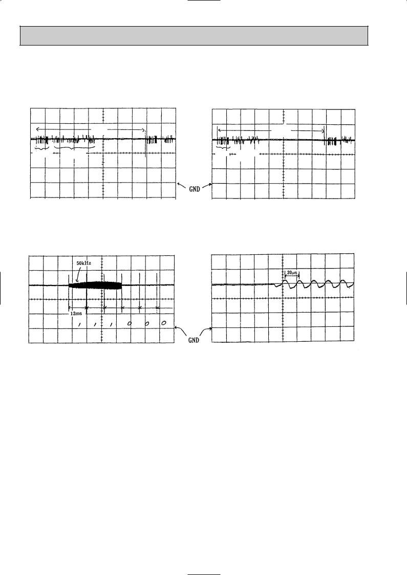
(3)The waveforms of from remote controller communications
The following graphs are the examples for measuring waveforms on the wirings of remote controlled transmission at the terminal block for remote controller.
a) A measuring example in the sequence of startup |
b) A measuring example during normal stop |
|
|
|
7.5 |
|
7.5 |
||
|
|
|
seconds |
||||
|
|
|
|
|
seconds |
||
|
|
|
|
|
|
|
|
|
|
|
|
|
|
|
|
Transmission |
|
Transmission |
|
Transmission |
|
Transmission |
|
from |
|
from |
|
from |
|
from |
|
remote |
|
indoor unit |
|
remote |
|
indoor unit |
|
controller |
|
|
|
controller |
|
|
|
|
|
|
|
|
|
|
|
|
|
|
|
|
|
|
|
5V/div, 1sec/div:
c) Expanded waveform 1 (signal 111000....)
5V/div, 1sec/div:
d) Expanded waveform 2 (50Hz carrier)
5V/div, 10msec/div: |
5V/div, 2µsec/div: |
•During normal operation, the remote controller interactively exchanges signals with the indoor unit of refrigerant address “0”. When the remote controller cannot receive signals from the indoor unit of refrigerant address “0” for 3 minutes, it is considered as abnormal. E0 is displayed on the remote controller as an error.
26

(4)The waveforms of communications between indoor and outdoor units
The following graphs are the examples for measuring waveforms on the wirings of connecting indoor and outdoor units at between S2 and S3 of the outdoor terminal block TB1.
a) A measuring example the sequence of startup: 1 |
b) A measuring example in the sequence of startup: 2 |
||||||||
|
|
|
|
|
|
|
|
|
|
|
Transmission |
|
Transmission |
|
|
|
|
|
|
|
from |
|
from |
|
|
|
|
|
|
|
indoor unit |
|
outdoor unit |
|
|
Transmission |
|
Transmission |
|
|
|
|
|
|
|
from |
|
from |
|
|
|
|
|
|
|||||
|
|
|
|
|
|
indoor unit |
|
outdoor unit |
|
|
|
|
|
|
|
|
|
|
|
10V/div, 500msec/div: |
|
10V/div, 500msec/div: |
|||||||||
c) A measuring example during normal stop |
d) A measuring example during normal stop |
||||||||||
(When one outdoor unit connects one indoor unit) |
(When one outdoor unit connects two indoor units) |
||||||||||
|
|
|
|
|
|
|
|
|
|
|
|
|
|
|
|
|
|
|
|
Transmission |
|
Transmission |
|
|
|
|
|
|
|
|
|
from |
|
from |
|
|
Transmission |
|
Transmission |
|
|
Transmission |
|
one indoor unit |
|
another |
|
|
from |
|
from |
|
|
from |
|
|
|
indoor unit |
|
|
|
|
|
|
|
||||||
|
indoor unit |
|
outdoor unit |
|
|
indoor unit |
|
|
|
|
|
|
|
|
|
|
|
|
|
|
|||
|
|
|
|
|
|
|
|
|
|
|
|
10V/div, 500msec/div: |
10V/div, 500msec/div: |
c) Expanded waveform
10V/div, 50msec/div:
•During normal operation, outdoor unit interactively exchanges signals with all the connected indoor units.
•When outdoor unit cannot receive signals for three minutes from an indoor unit due to any trouble like cable disconnection, it is considered as abnormal and the outdoor unit stops. E8 is displayed on the remote controller. This is to avoid independent operation of indoor units.
27

(5) Start-up system
A control unit is applicable to any models of standard (1:1), twin and triple without switch setting according to carrying out the below process automatically when the power is supplied.
When the power is supplied, following processes of 1 Refrigerant address transmitting, 2 Power supply control to remote controller, 3 Set number of the connected unit, 4 Set number of the indoor unit, 5 Duplication detection, 6 Collecting the unit information and 7 Collecting the operation data are carried out as shown on the figure.
Also when detecting the duplicated setting in the step 5, back to the first step and reset it.
Power ON
1 Refrigerant address |
|
transmitting |
|
2 Refrigerant |
YES |
address "0"? |
|
|
Power supply control |
NO |
to remote controller |
|
3Set number of the connected unit
4 Set number of the indoor unit
5 Duplication |
YES |
detection |
|
NO |
|
6 Collecting the unit information
7 Collecting the
operation data
;Transmitting the switch setting contents on the outdoor unit remote controller
(SW1-3~6)
;Feeding control to remote controller
Feeding the indoor unit of the refrigerant address “0”
;If there are 2 or more specified indoor unit, back to the first step.
;Collecting the vane, louver information and transmittance to the remote controller.
;Collecting the preceding operation setting information and transmittance to the remote controller.
EA error if 4 minutes have passed since the power is supplied.
EB error if 4 minutes have passed since the power is supplied.
EC error if 4 minutes have passed since the power is supplied.
Set up finish
<<Feature>>
A.Start-up time from the second time will be shorter since setting of the number of connected units is memorized once set. Start-up time can be estimated as following;
•When installing ... 1~2 minutes (Depending the number of connecting units)
•Since the second time .... 20 seconds ~ 1 minute (Depending the number of connecting units)
w When the above processing does not finish, even if 4 minutes have passed, consider the processing an error and Ea, Eb or Ec will be displayed.
However if power is not supplied to the indoor unit due to miss-wiring or looseness of the connecting lines between the indoor and outdoor unit, there will be no display on the remote controller. Also when the data can not be received from the outdoor unit, E6 is displayed on the remote controller after 6 minutes.
B. When replacing the p.c.board, only the unit number which has had it`s p.c.board replaced is reset. Even if the power supply is reset, the unit number which has not had it`s replaced does not change.
C. Automatic set unit is possible to confirm by blinking the frequency of LED3 in the indoor controller board.
At intervals of approx. 3 seconds, the number of the unit-number blinks.(Example:The unit(unit number:2) blinks twice at
3-second intervals.
Example
2 blinking Not lighted 2 blinking
3 seconds
28
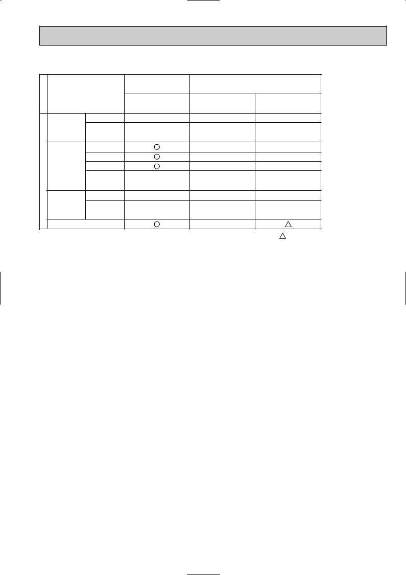
Function/control specifications
|
|
|
4-way ceiling cassette |
Ceiling concealed |
|
|
|
|
Item |
|
|
|
|
|
|
|
PLA-RP•AA |
PEA-RP•EA |
PEAD-RP•EA |
|
|
Fan |
Number of fan speed |
4 |
2 |
|
2 |
|
|
Drive method |
Pulsation |
Tap-changing |
Tap-changing |
|
/ specification |
|
|
(AC motor) |
(AC motor) |
(AC motor) |
|
Up/down |
Provided |
|
— |
|
— |
|
auto vane |
Swing function |
|
— |
|
— |
|
|
Shutter mechanism |
|
— |
|
— |
|
|
Moter type |
Stepping |
— |
|
— |
|
Function |
|
|
||||
|
|
(12V DC) |
|
|||
|
|
|
|
|
||
Left/right |
Provided |
— |
— |
|
— |
|
swing louver |
Moter type |
|
|
|
|
|
|
— |
— |
|
— |
||
|
|
|
|
|||
|
Drain pump |
|
— |
|
|
|
|
|
|
|
Note: The parts marked |
are optional. |
|
29
7 |
|
INDOOR UNIT CONTROL |
|
|
|||
|
|
|
|
|
|
|
|
7-1. COOL operation |
|
|
|||||
|
|
|
|
|
|
||
Control modes |
|
|
Control details |
Remarks |
|||
|
|
|
|
|
|||
1. Compressor |
1-1. Thermoregulating function (Function to prevent restarting for 3 minutes) |
w1 The thermoregulating |
|
||||
|
|
|
|
|
• Room temperature ] desired temperature +1:···Compressor ON |
function is provided in the |
|
|
|
|
|
|
outdoor unit. |
||
|
|
|
|
|
• Room temperature [ desired temperature ···Compressor OFF |
The indoor unit transmits |
|
|
|
|
|
|
Crankcase heater: OFF when compressor operates |
the indoor room |
|
|
|
|
|
|
temperature and set |
||
|
|
|
|
|
|
||
|
|
|
|
|
ON when compressor stopped (including when thermo is OFF) |
temperature data to |
|
|
|
|
|
|
Crankcase heater switches ON when 220-240V AC current is applied between |
outdoor unit, then the |
|
|
|
|
|
|
outdoor unit controls |
||
|
|
|
|
|
connectors CH 1 and 2 on the outdoor control board. |
thermoregulation. |
|
|
|
|
|
|
|
|
|
|
|
|
|
|
|
|
|
|
|
|
1-2. Anti-freezing control |
Refer to w2. |
|||
|
|
|
|
|
Detected condition : When the liquid pipe temperature (TH2 ) or Condenser/ |
Refer to w3. |
|
|
|
|
|
|
|
|
|
|
|
|
|
|
Evaporator temperature (TH5 ) (w3) is 2: or less (w4) in 16 |
|
|
|
|
|
|
|
minutes from compressors start up, anti-freezing control |
|
|
|
|
|
|
|
starts and the compressor will be suspended. |
|
|
|
|
|
|
|
Released condition : The timer which prevents reactivating is set for 3 minutes, |
|
|
|
|
|
|
|
and antifreezing control is cancelled when any one of the |
|
|
|
|
|
|
|
following conditions is satisfied. |
|
|
|
|
|
|
|
1 Liquid pipe temperature (TH2) and Condenser / Evaporator |
|
|
|
|
|
|
|
temperature (TH5) turn 10: or above. |
|
|
|
|
|
|
|
2 The condition of the compressor stop has become |
|
|
|
|
|
|
|
complete by thermoregulating, etc. |
|
|
|
|
|
|
|
3 The operation modes became mode other than COOL. |
|
|
|
|
|
|
|
4 The operation stopped. |
|
|
1-3. Frozen protection
Detected condition : 1 When the indoor pipe temperature (TH2 ) or Condenser/ Evaporator temperature (TH5 ) continues -15: for 3 minutes since 3 minutes has passed after the compressor start, the compressor stops and then the mode changes to prevent restarting for 6 minutes. After restarting of 6 minutes, when the indoor pipe temp. (TH2) or Condenser / Evaporator temperature (TH5) continues -15 or less for three minutes again by the time 16 minutes have passed, the frozen protection operates. (P6)
Detected condition : 2 In case the indoor unit continues to be under the anti-freezing control for 9 minutes or more, the unit will be in a state of the suspensive abnormality. Restart the compressor after releasing the anti-freezing control. The suspensive abnormality will be cancelled if the compressor keeps operating for 20 minutes. However, the suspensive abnormality will turn into the abnormality if the anti-freezing control works again for 9 minutes during that period. On the other hand, the suspensive abnormality will be cancelled if the anti-freezing control works for less than 9 minutes
Released condition : When the operation stops by the remote controller operation.
2. Fan |
By the remote controller setting (switch of 4 speeds or 2 speeds) |
||||
|
When determining the abnormality of the pipe temp. low speed fan is fixed. |
||||
|
|
|
|
|
|
|
|
Type |
Fan speed notch |
|
|
|
|
|
|
|
|
|
|
4 speeds type |
[Low] [Mid2] [Mid1] [High] |
|
|
|
|
|
|
|
|
|
|
2 speeds type |
[Low] |
[High] |
|
|
|
|
|
|
|
w2 Compare liquid pipe temperature to Condenser/ Evaporator temperature, and the lower one is applied to anti-freezing control.
•Liquid pipe temperature [ Condenser/ Evaporator temperature····· Liquid pipe
•Liquid pipe temperature > Condenser/ Evaporator temperature····· Condenser/ Evaporator pipe w3 The function of remote controller can change the temperature to start anti-freezing control.
30
 Loading...