


Contents
1. |
Safety Precautions ................................................................ |
2 |
7. |
Other Functions................................................................... |
11 |
2. |
Parts Names.......................................................................... |
2 |
8. |
Function Selection............................................................... |
12 |
3. |
Screen Configuration............................................................. |
5 |
9. |
Emergency Operation for Wireless Remote-controller........ |
16 |
4. |
Setting the Day of the Week and Time.................................. |
5 |
10.Care and Cleaning .............................................................. |
16 |
|
5. |
Operation............................................................................... |
5 |
11.Troubleshooting................................................................... |
17 |
|
6. |
Timer ..................................................................................... |
8 |
12.Specifications ...................................................................... |
18 |
|
Note
Fig. 1
This symbol mark is for EU countries only.
This symbol mark is according to the directive 2002/96/EC Article 10 Information for users and Annex IV, and/or to the directive 2006/66/EC Article 20 Information for end-users and Annex II.
Your MITSUBISHI ELECTRIC product is designed and manufactured with high quality materials and components which can be recycled and/or reused. This symbol means that electrical and electronic equipment, batteries and accumulators, at their end-of- life, should be disposed of separately from your household waste. If a chemical symbol is printed beneath the symbol (Fig. 1), this chemical symbol means that the battery or accumulator contains a heavy metal at a certain concentration.
This will be indicated as follows: Hg: mercury (0,0005%), Cd: cadmium (0,002%), Pb: lead (0,004%)
In the European Union there are separate collection systems for used electrical and electronic products, batteries and accumulators. Please, dispose of this equipment, batteries and accumulators correctly at your local community waste collection/recycling centre. Please, help us to conserve the environment we live in!
1. Safety Precautions
Before installing the unit, make sure you read all the “Safety Precautions”.
The “Safety Precautions” provide very important points regarding safety. Make sure you follow them. Please report to or take consent by the supply authority before connection to the system.
Symbols used in the text
 Warning:
Describes precautions that should be observed to prevent danger of injury or death to the user.
 Caution:
Describes precautions that should be observed to prevent damage to the unit.
Symbols used in the illustrations
 : Indicates a part which must be grounded.
 Warning:
•For appliances not accessible to the general public.
•The unit must not be installed by the user. Ask the dealer or an authorized company to install the unit. If the unit is installed improperly, water leakage, electric shock or fire may result.
•Do not stand on, or place any items on the unit.
•Do not splash water over the unit and do not touch the unit with wet hands. An electric shock may result.
•Do not spray combustible gas close to the unit. Fire may result.
•Do not place a gas heater or any other open-flame appliance where it will be exposed to the air discharged from the unit. Incomplete combustion may result.
•Do not remove the front panel or the fan guard from the outdoor unit when it is running.
•When you notice exceptionally abnormal noise or vibration, stop operation, turn off the power switch, and contact your dealer.
•Never insert fingers, sticks etc. into the air inlets or outlets.
•If you detect odd smells, stop using the unit, turn off the power switch and consult your dealer. Otherwise, a breakdown, electric shock or fire may result.
•This air conditioner is NOT intended for use by children or infirm persons without supervision.
•Young children must be supervised to ensure that they do not play with the air conditioner.
•If the refrigeration gas blows out or leaks, stop the operation of the air conditioner, thoroughly ventilate the room, and contact your dealer.
 Caution:
•Do not use any sharp object to push the buttons, as this may damage the remote controller.
•Never block or cover the indoor or outdoor unit’s air inlets or outlets.
Disposing of the unit
When you need to dispose of the unit, consult your dealer.
2. Parts Names |
|
|
|
Indoor Unit |
|
PKA-RP·KAL |
|
|
PKA-RP·KAL |
Front grille |
|
|
|
||
Fan speed |
3 speeds (with auto) |
|
|
Vane |
Auto swing |
Filter |
|
Louver |
Manual |
||
|
|||
Filter |
Normal |
Air inlet |
|
Filter cleaning indication |
100 hr |
|
Air outlet
Emergency operation switch
Louver
Vane
2

2. Parts Names
Wired Remote-Controller
Display Section
For purposes of this explanation, |
|
|
|
Day-of-Week |
|
all parts of the display are shown |
|
|
|
Shows the current day of the week. |
|
as lit. During actual operation, |
|
|
|
|
|
|
|
|
|
|
|
only the relevant items will be |
|
|
|
|
|
|
|
|
|
|
|
|
|
|
Time/Timer Display |
||
displayed. |
|
|
|
||
|
|
|
Shows the current time, unless the simple or Auto Off |
||
|
|
|
|
||
|
|
|
|
timer is set. |
|
|
|
|
|
If the simple or Auto Off timer is set, shows the time |
|
|
|
|
|
remaining. |
|
Identifies the current operation |
|
|
|||
|
|
|
|
|
|
Shows the operation mode, etc.
*Multi language display is supported.
|
TIME SUN MON TUE WED THU FRI SAT |
||
|
TIMER |
Hr |
ON |
|
AFTER |
AFTER |
OFF |
|
ERROR CODE |
|
FUNCTION |
|
°F°C |
|
FILTER |
“Centrally Controlled” indicator |
°F°C |
|
|
|
WEEKLY |
||
Indicates that operation of the |
ONLY1Hr. |
|
SIMPLE |
|
AUTO OFF |
||
remote controller has been |
|
|
|
prohibited by a master controller. |
|
|
|
|
|
|
|
|
|
|
|
|
|
|
|
|
|
|
|
Airflow up/down direction indicator |
|
|
|
Room Temperature display |
|
||
|
|
|
|
|
|
|
|
|
|
Shows the room temperature. The room |
|
“Timer is Off” indicator |
|
|
|
The indicator |
shows the direction |
|
|
||||
|
|
||||||||||
|
|
|
|
of the outcoming airflow. |
|
|
|
temperature display range is 8–39 °C. |
|
||
Indicates that the timer is off. |
|
|
|
|
|
||||||
|
|
|
|
|
The display blinks if the temperature is |
|
|||||
|
|
|
|
|
|
|
|
|
|
|
|
|
|
|
|
|
|
|
|
|
|
less than 8 °C or 39 °C or more. |
|
|
|
|
|
|
|
|
|
|
|
|
|
|
|
|
|
“One Hour Only” indicator |
|
|
|
||||
|
|
|
|
|
|
|
|
|
|||
|
|
|
|
|
|
|
|||||
|
|
|
|
|
|
|
|
|
|
|
|
|
|
|
|
|
|
|
|
|
|
|
|
|
|
|
|
Displayed if the airflow is set to Low |
|
|
|
Louver display |
|
||
Temperature Setting |
|
|
|
and downward during COOL or DRY |
|
|
|
Indicates the action of the swing louver. |
|
||
Shows the target temperature. |
|
|
|
operation mode. (Operation varies |
|
|
|
Does not appear if the louver is |
|
||
|
|
|
|
according to model.) |
|
|
|
stationary. |
|
||
|
|
|
|
|
|
|
|||||
|
|
|
|
The indicator goes off after one hour |
|
|
|
|
|
||
|
|
|
|
|
|
|
|
|
|||
|
|
|
|
|
|
|
|
|
|||
|
|
|
|
when the airflow up/down direction |
|
|
|
(Power On indicator) |
|
||
|
|
|
|
also changes. |
|
|
|
|
|
||
|
|
|
|
|
|
|
|
Indicates that the power is on. |
|
||
|
|
|
|
|
|
|
|
|
|
|
|
|
|
|
|
|
|
|
|
|
|
|
|
|
|
|
|
|
|
|
|
|
|
|
|
“Sensor” indicator
Displayed when the remote controller sensor is used.
“Locking function” indicator
Indicates that remote controller buttons have been locked.
“Clean the filter” indicator
Comes on when it is time to clean the filter.
Timer indicators
The indicator comes on if the corresponding timer is set.
Fan Speed indicator
Shows the selected fan speed.
Ventilation indicator
Appears when the unit is running in Ventilation mode.
Operation Section |
|
|
|
|
|
|
|
Temperature set buttons |
|
|
|
|
ON/OFF button |
||
Down |
|
|
|
|
Fan Speed button |
||
|
|
|
|
|
|||
Up |
|
|
|
|
|
|
|
Timer Menu button |
|
|
|
|
|
|
|
(Timer monitor/Timer set button) |
|
|
|
|
|
|
|
Operation mode button |
|
|
|
|
Filter |
button |
|
|
|
|
|
(<Enter> button) |
|||
(Back button) |
|
|
|
|
|
|
|
|
TEMP. |
|
|
ON/OFF |
Test Run button |
||
|
|
|
|
|
|
||
Set Time buttons |
|
|
|
|
Check button |
||
Back |
MENU |
ON/OFF |
|
|
(Clear button) |
||
|
FILTER |
|
|
||||
Ahead |
MONITOR/SET |
DAY |
|
CHECK |
TEST |
|
|
BACK |
|
|
|
||||
PAR-21MAA |
CLOCK |
OPERATION |
CLEAR |
Airflow up/down button |
|||
|
|
|
|||||
Timer On/Off button |
|
|
|
|
|
|
|
(Set Day button) |
|
|
|
|
Louver button |
||
|
|
|
|
|
( |
Operation button) |
|
Opening the |
|
|
|
|
|
|
To preceding |
|
|
|
|
|
|
operation number. |
|
door. |
|
|
|
|
|
|
|
|
|
|
|
|
|
|
|
Ventilation button
( Operation button)
Built-in temperature sensor |
To next operation |
|
|
|
number. |
Note:
“PLEASE WAIT” message
This message is displayed for approximately 3 minutes when power is supplied to the indoor unit. “NOT AVAILABLE” message
This message is displayed if a button is pressed to operate a function that the indoor unit does not have.
If a single remote controller is used to simultaneously operate multiple indoor units that are different models, this message will not be displayed if any of the indoor units is equipped with the function.
3

2. Parts Names
Wireless Remote-Controller
Remote controller display
* For explanation purposes, all of the items that appear in the display are shown.
* All items are displayed when the Reset button is pressed.
ON/OFF button
Temperature set buttons
Fan Speed button (Changes fan speed)
Airflow button (Changes airflow up/down direction)
Mode button (Changes operation mode)
Check button
Test Run button
When using the wireless remote controller, point it towards the receiver on the indoor unit. If the remote controller is operated within approximately two minutes after power is supplied to the indoor unit, the indoor unit may beep twice as the unit is performing the initial automatic check.
The indoor unit beeps to confirm that the signal transmitted from the remote controller has been received. Signals can be received up to approximately 7 meters in a direct line from the indoor unit in an area 45° to the left and right of the unit. However, illumination such as fluorescent lights and strong light can affect the ability of the indoor unit to receive signals.
If the operation lamp near the receiver on the indoor unit is flashing, the unit needs to be inspected. Consult your dealer for service.
Handle the remote controller carefully! Do not drop the remote controller or subject it to strong shocks. In addition, do not get the remote controller wet or leave it in a location with high humidity.
To avoid misplacing the remote controller, install the holder included with the remote controller on a wall and be sure to always place the remote controller in the holder after use.
Outdoor unit
Power
Ref. Pipes
Indoor-Outdoor
Connection wire
Earth
Service Panel
Transmission area
Transmission indicator
Timer indicator
Operation areas
Timer Off button
Timer On button
Hour button
Minute button
Set Time button (Sets the time)
Louver button (Changes left/right direction)
Reset button
Battery installation/replacement
1.Remove the top cover, insert two AAA batteries, and then install the top cover.
1
Top cover

 2
2  3
3
Two AAA batteries
Insert the negative
(–) end of each battery first. Install the batteries in the correct directions (+, –)!
2. Press the Reset button.
Press the Reset button with an object that has a narrow end.
4

3. Screen Configuration
Function Selection of remote controller |
Set Day/Time |
|
|
TIME SUN |
|
A |
D |
C |
Standard Control Screens |
|
|
|
°C |
°F°C |
|
|
|
OFF |
ON |
|
B |
C |
|
Timer Monitor |
Timer Setup |
|
MON |
SUN MON TUE |
WED THU |
FRI SAT |
TIMER |
|
|
|
OFF |
B |
|
|
°F°C |
|
|
|
WEEKLY |
|
|
WEEKLY |
<Screen Types>
For details on setting the language for the remote controller display, refer to section 8. Function Selection.
The initial language setting is English. Function Selection of remote controller:
|
Set the functions and ranges available to the |
|
remote controller (timer functions, operating |
|
restrictions, etc.) |
Set Day/Time: |
Set the current day of the week or time. |
Standard Control Screens: |
|
|
View and set the air conditioning system’s |
|
operating status |
Timer Monitor: |
View the currently set timer (weekly timer, |
|
simple timer, or Auto Off timer) |
Timer Setup: |
Set the operation of any of the timers (weekly |
|
timer, simple timer, or Auto Off timer). |
<How to change the screen>
A : Hold down both the Operation mode button and the Timer On/Off button for 2 seconds.
B : Press the Timer Menu button.
C : Press the Operation mode (Back) button.
D : Press either of the Set Time buttons ( or
or  ).
).
4. Setting the Day of the Week and Time
|
1 |
3 Day of the Week Setting |
|
Day of the Week |
2 |
|
|
|
& Time display |
TIME SUN |
4 |
Time Setting |
|
TIME SUN |
|
|
|
|
°C |
°C |
|
|
|
|
TEMP. |
ON/OFF |
9 |
2 |
|
MENU |
ON/OFF |
FILTER |
4 |
1. Press the |
or |
Set Time button a to show display 2. |
|
BACK MONITOR/SET |
DAY |
CHECK TEST |
|
2. Press the Timer On/Off (Set Day) button 9 to set the day. |
|||
|
PAR-21MAA |
CLOCK |
OPERATION CLEAR |
|
* Each press advances the day shown at 3 : |
|||
a |
|
|
|
|
|
Sun → Mon → ... → Fri → Sat. |
||
|
|
|
|
|
|
3. Press the appropriate Set Time button a as necessary to set the |
||
|
|
|
|
|
|
time. |
|
|
Note: |
|
|
|
|
|
* As you hold the button down, the time (at 4) will increment first in |
||
The day and time will not appear if clock use has been disabled at Function |
minute intervals, then in ten-minute intervals, and then in one-hour |
|||||||
Selection of remote controller. |
|
|
intervals. |
|
|
|||
4. After making the appropriate settings at Steps 2 and 3, press the Filter  button 4 to lock in the values.
5. Operation
|
|
|
|
|
6 |
2 |
|
|
|
|
4 |
|
|
|
|
|
5 |
3 |
°C |
|
°C |
|
8 |
|
|
|
|
||
|
|
|
|
7 |
|
3 |
TEMP. |
|
|
ON/OFF |
|
|
|
|
|||
2 |
|
|
|
|
1 |
MENU |
ON/OFF |
|
FILTER |
||
|
|
|
|
|
|
BACK |
MONITOR/SET |
DAY |
|
CHECK |
TEST |
PAR-21MAA |
CLOCK |
OPERATION |
CLEAR |
1 |
|
|
|
|
|
|
|
|
|
|
|
|
5 |
5.1. Turning ON/OFF |
|
7 8 |
6 |
||
|
|
|
|
||
<To Start Operation>
Press the ON/OFF button 1.
• The ON lamp 1 and the display area come on.
2 |
3 |
5 |
|
6 |
7 |
|
1

 3
3
5
2
 6
6
7
5
5. Operation
<To Stop Operation>
Press the ON/OFF button 1 again.
• The ON lamp 1 and the display area go dark.
Note:
Even if you press the ON/OFF button immediately after shutting down the operation is progress, the air conditioner will not start for about three minutes. This is to prevent the internal components from being damaged.
5.2. Operation mode select
Press the operation mode (


 ) button 2 and select the operation mode 2.
Cool mode
Dry mode
 Fan mode
 Heat mode <Only heat pump type>

 Automatic (cool/heat) operation mode <Only heat pump type>


 Ventillation mode
Only indicated on the following condition Wired remote controller used LOSSNAY connected
Automatic operation
According to a set temperature, cooling operation starts if the room temperature is too hot and heating operation starts if the room temperature is too cold.
During automatic operation, if the room temperature changes and remains 2 °C or more above the set temperature for 15 minutes, the air conditioner switches to cool mode. In the same way, if the room temperature remains 2 °C or more below the set temperature for 15 minutes, the air conditioner switches to heat mode.
Cool mode |
15 minutes (switches |
||||||
|
|
|
from heating to cooling) |
||||
|
|
|
|
|
|
|
Set temperature +2°C |
|
|
|
|
|
|
|
|
|
|
|
|
|
|
|
Set temperature |
|
|
|
|
|
|
|
|
Set temperature -2°C
15 minutes (switches from cooling to heating )
Because the room temperature is automatically adjusted in order to maintain a fixed effective temperature, cooling operation is performed a few degrees warmer and heating operation is performed a few degrees cooler than the set room temperature once the temperature is reached (automatic energy-saving operation).
5.3. Temperature setting
To decrease the room temperature:
Press  button 3 to set the desired temperature. The selected temperature is displayed 3.
To increase the room temperature:
Press  button 3 to set the desired temperature.
The selected temperature is displayed 3.
• Available temperature ranges are as follows:
Cooling/Drying: |
19 - 30 °C |
Heating: |
17 - 28 °C |
Automatic: |
19 - 28 °C |
•The display flashes either 8 °C - 39 °C to inform you if the room temperature is lower or higher than the displayed temperature.
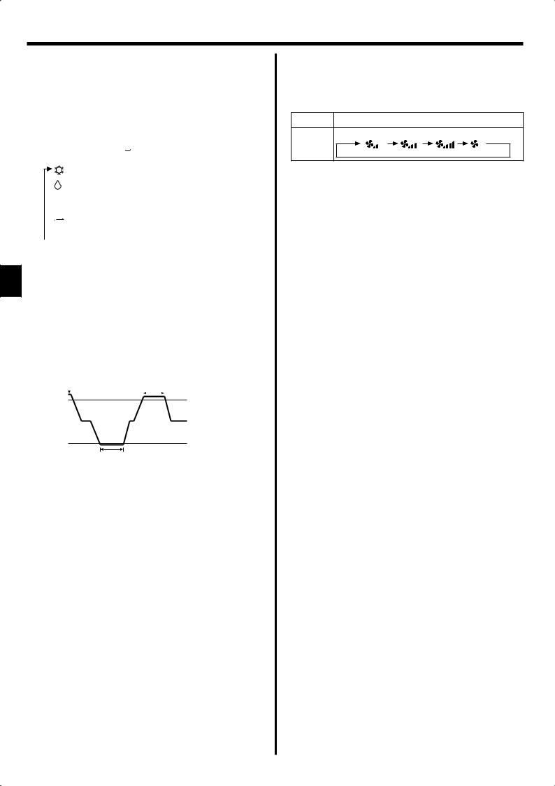
5.4. Fan speed setting
Press the Fan Speed button 5 as many times as necessary while the system is running.
•Each press changes the force. The currently selected speed is shown at 5.
•The change sequence, and the available settings, are as follows.
FAN SPEED |
|
|
Display |
|
3-speed |
Speed 1 |
Speed 2 |
Speed 3 |
Auto |
+ |
|
|
|
|
Auto |
|
|
|
|
Note:
The number of available fan speeds depends on the type of unit connected. Note also that some units do not provide an “Auto” setting.
In the following cases, the actual fan speed generated by the unit will differ from the speed shown the remote controller display.
1.While the display is showing “STAND BY” or “DEFROST”.
2.When the temperature of the heat exchanger is low in the heat mode. (e.g. immediately after heat operation starts)
3.In HEAT mode, when room temperature is higher than the temperature setting.
4.When the unit is in DRY mode.
6
 Loading...