

Page 1

General ........................
00
WORKSHOP
MANUAL
SUPPLEMENT
FOREWORD
This manual outlines changes in servicing
procedures related to the chassis including
vehicle inspections and adjustments in the
newly added models. Use the following
manuals in combination with this manual as
required.
TECHNICAL INFORMATION MANUAL
PYJE9002
WORKSHOP MANUAL
ENGINE GROUP PWEE____
(Looseleaf edition)
CHASSIS GROUP PWJE9086(Basic)
PWJE9086-G(Supplement)
PWJE9086-H(Supplement)
PWJE9086-I(Supplement)
ELECTRICAL WIRING PHJE9026(Basic)
PHJE9026-D(Supplement)
PHJE9026-E(Supplement)
PHJE9026-F(Supplement)
PHJE9026-G(Supplement)
PHJE9026-H(Supplement)
PHJE9026-I(Supplement)
PARTS CATALOGUE B60356A2Aj
Engine .........................
Engine Lubrication .............
Fuel ...........................
Engine Cooling ................
Intake and Exhaust .............
Engine Electrical ...............
Engine and Emission Control . . .
Interior and Supplemental
Restraint System (SRS) ........
Chassis Electrical ..............
11
12
13
14
15
16
17
52
54
All information, illustrations and product
descriptions contained in this manual are
current as at the time of publication. We,
however, reserve the right to make changes
at any time without prior notice or obligation.
E Mitsubishi Motors Corporation May 2001
Page 2
GENERAL - How to Use This Manual/Vehicle Identification
ith
turboch
ith
turboch
00-1
GROUP 00
GENERAL
HOW TO USE THIS MANUAL
INDICATION OF TIGHTENING TORQUE
Tightening torques (units: N·m) are set to take into account the central value and the allowable tolerance.
The central value is the target value, and the allowable tolerance provides the checking range for tightening
torques. If bolts and nuts are not provided with tightening torques, refer to P.00-5.
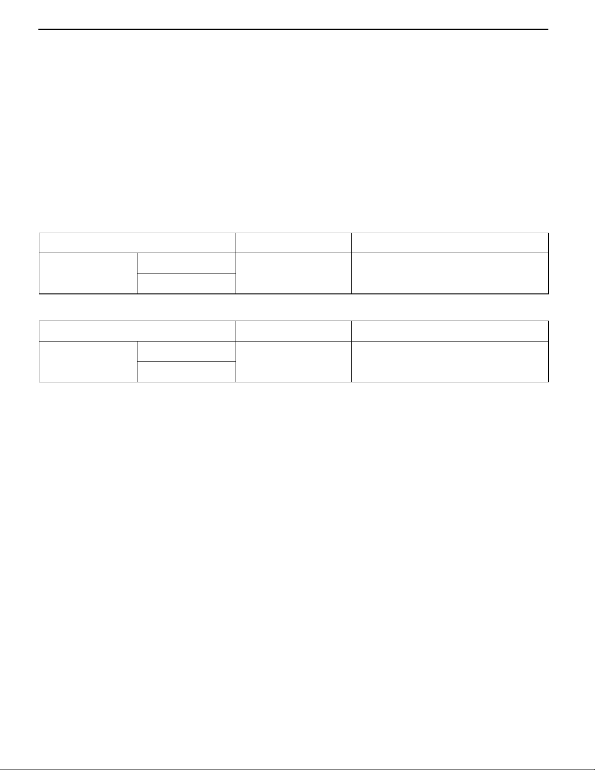
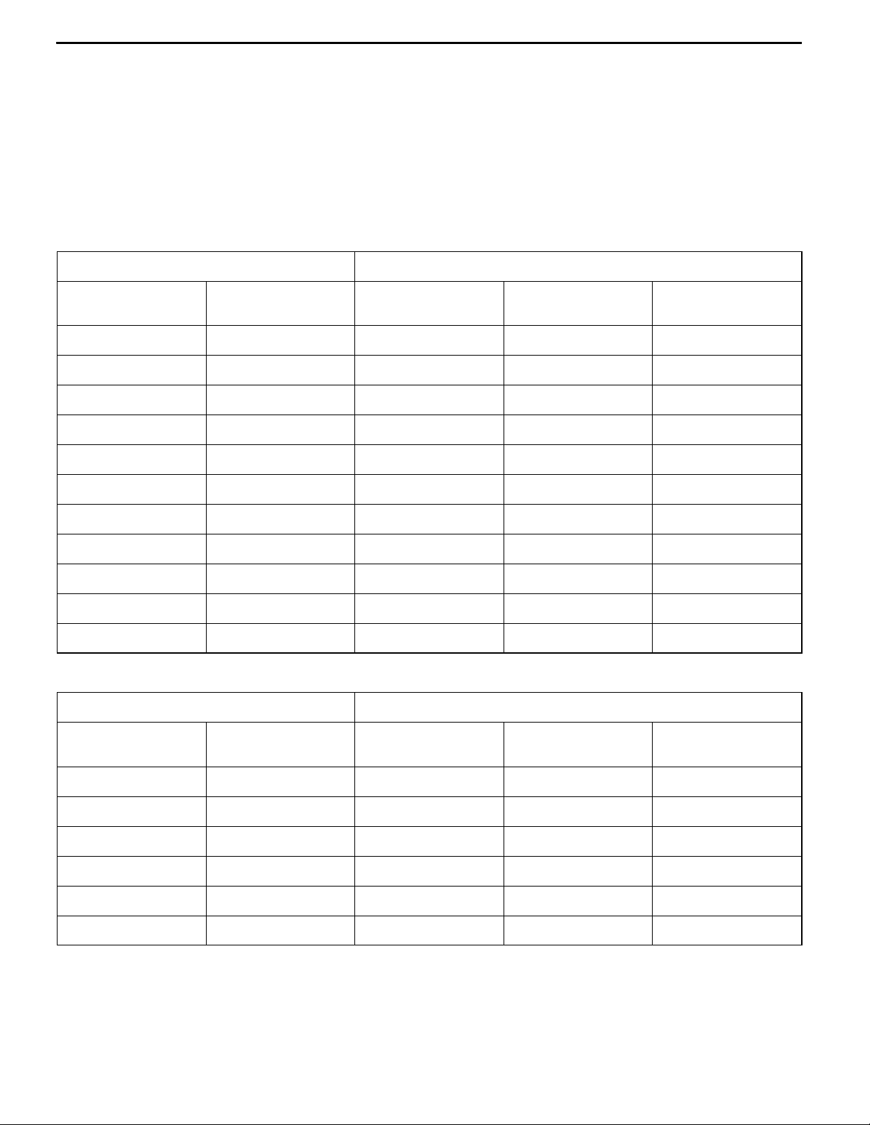
VEHICLE IDENTIFICATION
MODELS
<2-DOOR MODELS>
Model code Engine model Transmission model Fuel supply system
V24W NDGL6Y 4D56 (2,477 mL)
w
GNDGL6Y
<4-DOOR MODELS>
Model code Engine model Transmission model Fuel supply system
V44W NDGL6Y 4D56 (2,477 mL)
GNDGL6Y
and inter-cooler
w
and inter-cooler
arger
arger
V5MT1 <5M/T> Injection
V5MT1 <5M/T> Injection
Page 3
00-2
GENERAL - Vehicle Identification
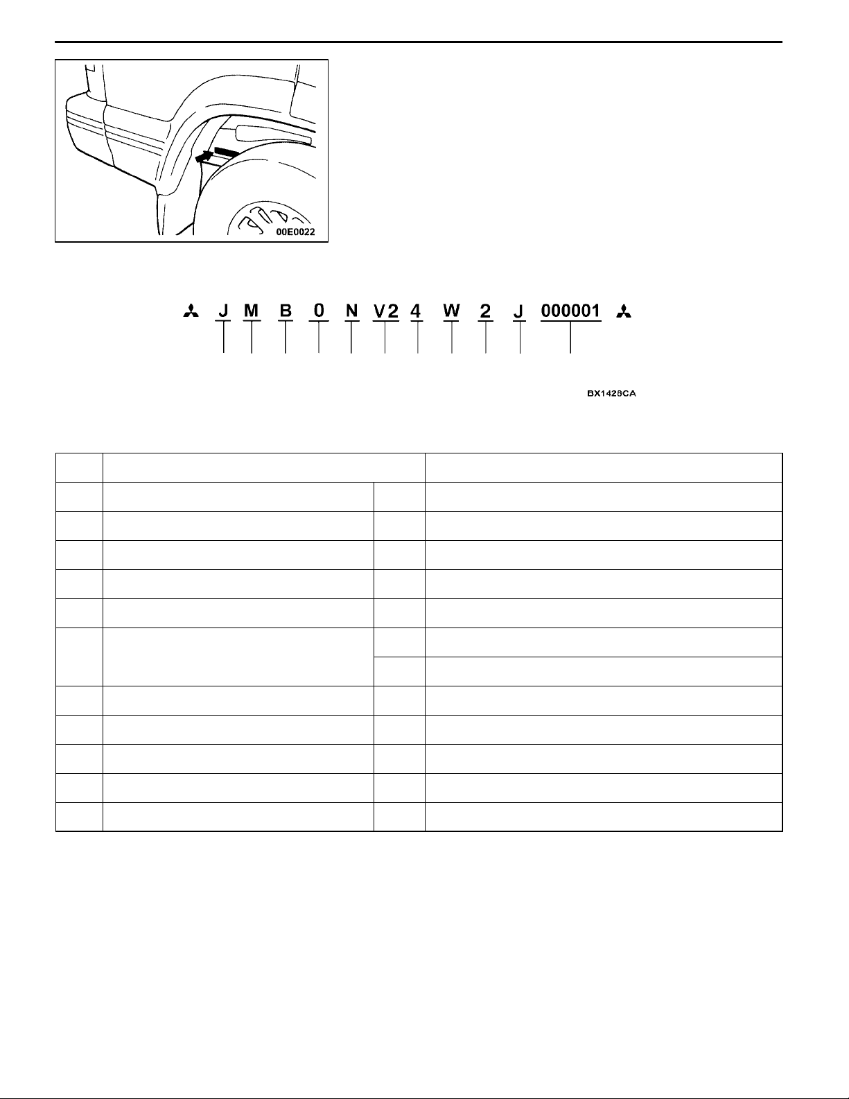
CHASSIS NUMBER
The chassis number is stamped on the side wall of the frame
near the right rear wheel.
12 3 4
No. Items Contents
1 Fixed figure J Asia
2 Distribution channel M Japan channel
3 Destination B For Europe, left hand drive
4 Body style 0 4 or 2-door with tailgate(back door)
5 Transmission type N 5-speed manual transmission
6 Development order V2 PAJERO 2-door models
7 Engine 4 4D56: 2,477 mL diesel engine
8 Sort W Station wagon
9 Model year 2* 2002
5
6
V4 PAJERO 4-door models
7
89
10
11
10 Plant J Pajero Manufacturing Co., Ltd. *
11 Serial number - -
NOTE
*: Indicates changes.
Page 4
GENERAL - Major SpecificationsGENERAL - Major Specifications
mm
g
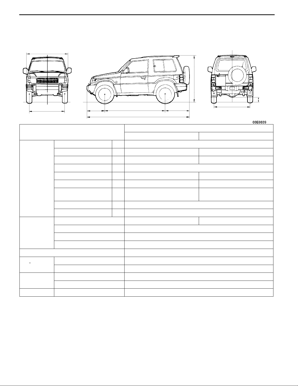
MAJOR SPECIFICATIONS
2-DOOR MODELS
2
5
84 9
00-3
3
7
6
1
Items
Vehicle
dimensions
Vehicle
weight kg
Seating capacity 5
Engine Model No. 4D56 Intercooler Turbocharger
Transmission
Fuel system Fuel supply system Injection
Overall length 1 4,075
Overall width 2 1,695 1,785
Overall height (unladen) 3 1,835 1,845
Wheelbase 4 2,420
Track-front 5 1,420 1,465
Track-rear 6 1,435 1,480
Ground clearance
(unladen)
Overhang-front 8 675
Overhang-rear 9 980
Kerb weight 1,700 1,755
Max. gross vehicle weight 2,510
Max. axle weight rating-front 1,070
Max. axle weight rating-rear 1,750
Total displacement mL 2,477
Model No. V5MT1
Type 5-speed manual
V24W
NDGL6Y GNDGL6Y
7 205 215
Page 5
00-4
mm
g
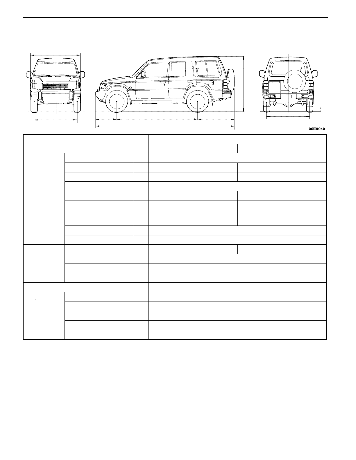
4-DOOR MODELS
2
5
GENERAL - Major Specifications
84
1
3
7
9
6
Items
Vehicle
dimensions
Vehicle
weight kg
Seating capacity 7
Engine Model No. 4D56 Intercooler Turbocharger
Transmission
Fuel system Fuel supply system Injection
Overall length 1 4,655
Overall width 2 1,695 1,775
Overall height (unladen) 3 1,890 1,900
Wheelbase 4 2,725
Track-front 5 1,420 1,465
Track-rear 6 1,435 1,480
Ground clearance
(unladen)
Overhang-front 8 650
Overhang-rear 9 1,280
Kerb weight 1,875 1,930
Max. gross vehicle weight 2,750
Max. axle weight rating-front 1,090
Max. axle weight rating-rear 1,780
Total displacement mL 2,477
Model No. V5MT1
Type 5-speed manual
V44W
NDGL6Y GNDGL6Y
7 205 215
Page 6
GENERAL - Standard Part/Tightening-Torque Table
STANDARD PART/TIGHTENING-TORQUE TABLE
00-5
Each torque value in the table is a standard value
for tightening under the following conditions.
(1) Bolts, nuts and washers are all made of steel
and plated with zinc.
(2) The threads and bearing surface of bolts and
nuts are all in dry condition.
The values in the table are not applicable:
(1) If toothed washers are inserted.
(2) If plastic parts are fastened.
(3) If bolts are tightened to plastic or die-cast
inserted nuts.
(4) If self-tapping screws or self-locking nuts are
used.
Standard bolt and nut tightening torque
Thread size Torque N·m
Bolt nominal
diameter (mm)
M5 0.8 2.50.5 5.01.0 6.01.0
M6 1.0 5.01.0 9.02.0 102
M8 1.25 122 224 254
M10 1.25 244 4410 537
M12 1.25 418 8312 9812
M14 1.5 7312 14020 15525
Pitch (mm) Head mark “4” Head mark “7” Head mark “8”
M16 1.5 11020 21030 23535
M18 1.5 16525 30040 34050
M20 1.5 22535 41060 48070
M22 1.5 30040 55585 64595
M24 1.5 39555 735105 855125
Flange bolt and nut tightening torque
Thread size Torque N·m
Bolt nominal
diameter (mm)
M6 1.0 5.01.0 102 122
M8 1.25 132 244 275
M10 1.25 264 499 587
M10 1.5 244 458 5510
M12 1.25 468 9515 10515
M12 1.75 438 8312 9812
Pitch (mm) Head mark “4” Head mark “7” Head mark “8”
NOTE
1. Be sure to use only the specified bolts and nuts, and always tighten them to the specified torques.
2. Bolts marked with indications such as 4T or 7T are reinforced bolts. The larger the number, the
greater the bolt strength.
Page 7

NOTES
Page 8

ENGINE
CONTENTS
11-1
ENGINE <4D5-Step III>2.............
GENERAL 2.................................
Outline of Changes 2...........................
GENERAL INFORMATION 2..................
SERVICE SPECIFICATIONS 2.................
SEALANT 3..................................
SPECIAL TOOLS 3...........................
ON-VEHICLE SERVICE 4.....................
Injection Timing Check and Adjustment 4.........
Idle Speed Check 4............................
OIL PAN AND OIL SCREEN 5................
TIMING BELT AND TIMING BELT B 7........
CYLINDER HEAD GASKET 11................
Page 9
G
l/G
l
Inf
11-2
ENGINE <4D5-Step III>-
enera
Specifications
enera
ormation/Service
ENGINE <4D5-Step
III
>
GENERAL
OUTLINE OF CHANGES
Some service procedures have been revised as the following changes have been made to comply to
the Emission Regulation Step III.
D The injection timing check and adjustment procedure and the idle speed check procedure have been
changed.
D The oil pan has a cover in order to reduce noise due to an enhanced engine output.
D A crank angle sensor and crankshaft sensing blade have been added due to the introduction of
an electronic-controlled fuel injection pump. Due to this change, the timing belt front lower cover
has been reshaped.
D The tightening torque of the cylinder head bolts and the cylinder head gasket have been changed.
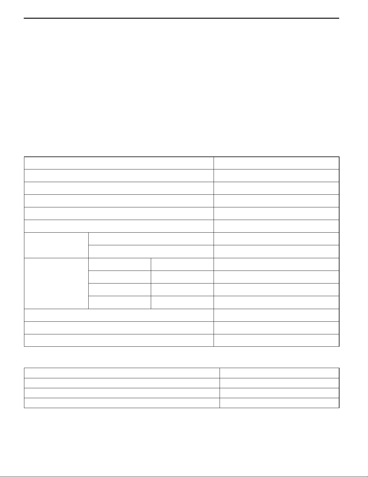
GENERAL INFORMATION
Items 4D56
Total displacement mL 2,477
Bore x Stroke mm 91.1 x 95.0
Compression ratio 21
Combustion chamber Vortex chamber type
Camshaft arrangement SOHC
Number of valve Intake 4
Exhaust 4
Valve timing Intake Opening BTDC 20_
Exhaust Closing ABDC 49_
Intake Opening BBDC 55_
Exhaust Closing ATDC 22_
Fuel system Electronically controlled type injection pump
Rocker arm Roller type
Adjusting screw Elephant foot type
SERVICE SPECIFICATIONS
Items Standard value
Timing belt tension mm 4-5
Timing belt B tension mm 4-5
Idle speed r/min 750 ± 30
Page 10
ENGINE <4D5-Step III>-Sealant/Special Tools
SEALANT
Items Specified sealant Remarks
11-3
Oil pan MITSUBISHI GENUINE PART
MD970389 or equivalent
Semi-circular packing and rocker
cover seal, and cylinder head seal
3M ATD Part No. 8660 or equivalent
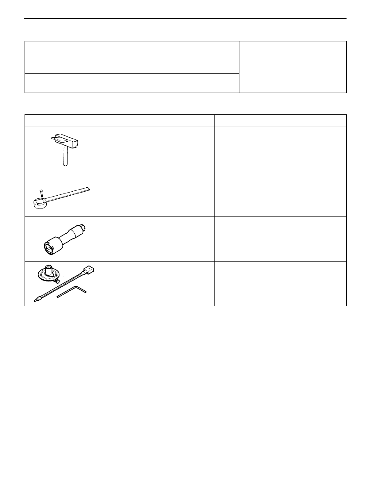
SPECIAL TOOLS
Tools Number Name Use
MD998727 Oil pan remover Removal of oil pan
MD998721 Crankshaft pulley
holder
MD998051 Cylinder head bolt
wrench
Semi-drying sealant
Holding the crankshaft pulley
Removal and installation of the cylinder head
bolt
MB991614 Angle gauge Tightening of the cylinder head bolts
Page 11
11-4
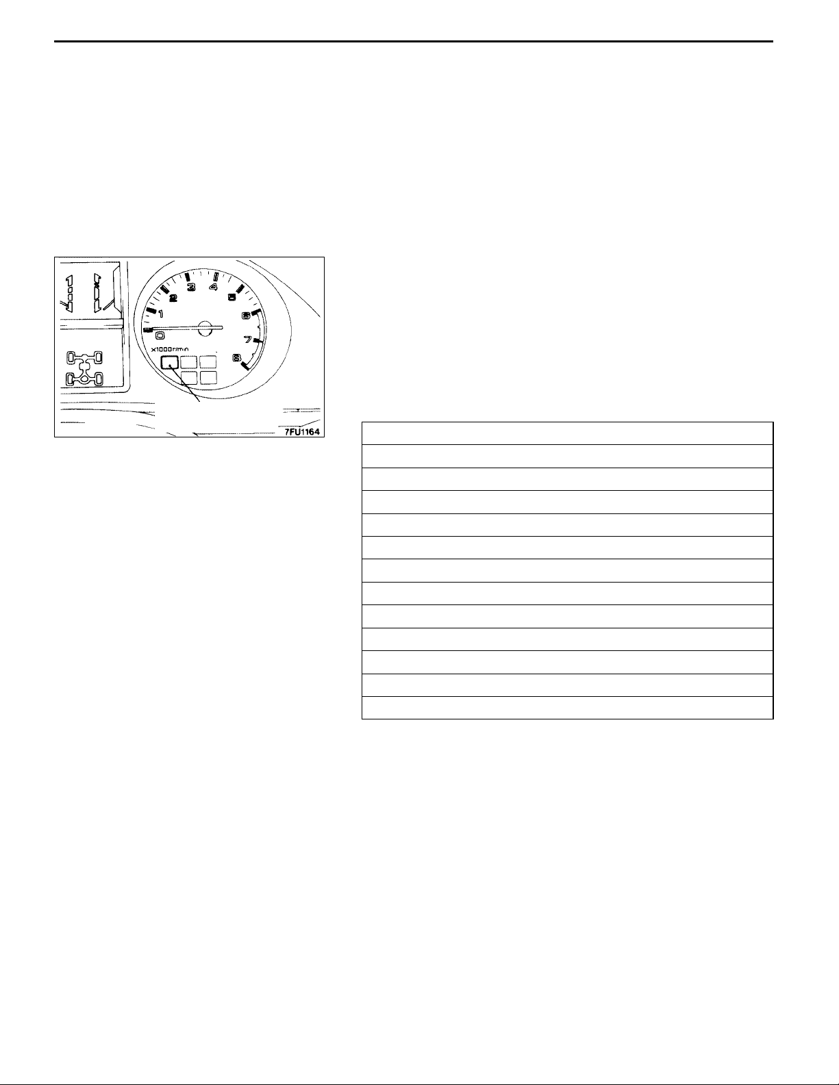
Tachometer
ENGINE <4D5-Step III>-On-vehicle Service
ON-VEHICLE SERVICE
INJECTION TIMING CHECK AND
ADJUSTMENT
The cold start device (wax type) has been discontinued as
an electronically controlled injection pump has been used.
The other inspection and adjustment procedures are the same
as before.
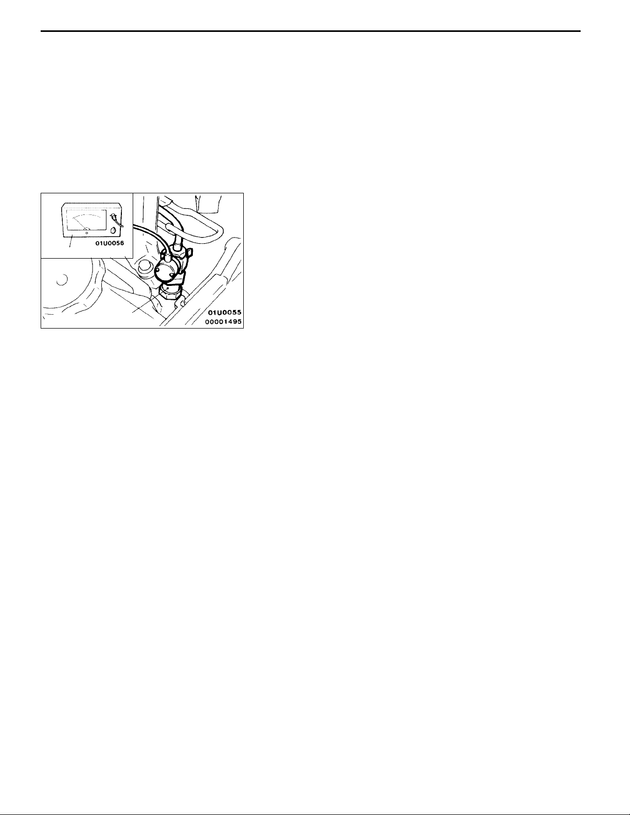
IDLE SPEED CHECK
1. Set the vehicle to the pre-inspection condition.
2. Turn the ignition switch to “LOCK” (OFF) position, and
connect the diagnosis connector to the MUT-II.
If the MUT-II is not used, connect a tachometer to the
injection nozzle or the pipe.
3. Start the engine, and let it run at idle.
4. Check the idle speed.
Injection nozzle
Standard value: 750 ± 30 r/min
5. If the idle speed is not within the standard value, refer
to 13C - Troubleshooting to check the electronic controlled
fuel injection system.
NOTE
The idle speed is controlled by the engine-ECU.
Page 12
ENGINE <4D5-Step III>-Oil Pan and Oil Screen
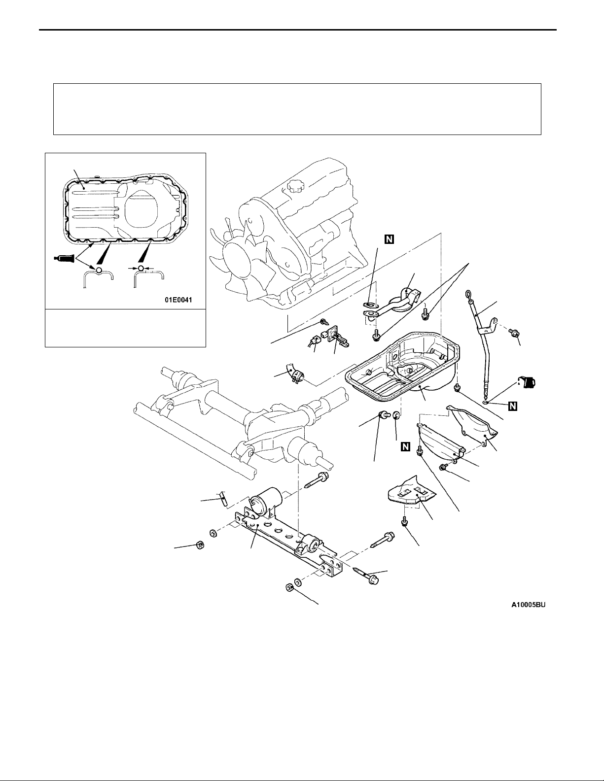
OIL PAN AND OIL SCREEN
REMOVAL AND INSTALLATION
11-5
Pre-removal and Post-installation Operation
D Skid Plate and Under Cover Removal and Installation.
D Front Exhaust Pipe Removal and Installation (Refer
to GROUP 15 - Exhaust Pipe and Muffler.)
12
4mm
(0.16 in.)
diameter
Hole of boltGroove
Sealant:
MITSUBISHI GENUINE Part No.
MD997110 or equivalent
9.0 ± 1.0 N·m
D Engine Oil Draining and Supplying.
15
19 ± 3 N·m
14
4
8
9
12 ± 1 N·m
7
(Engine oil)
12
1
110 ± 10 N·m
Removal steps
1. Vacuum hose connection
2. Bolt
3. Front suspension crossmember
4. Engine oil level gauge and guide
assembly
5. Drain plug
"BA 6. Drain plug gasket
7. Alternator vacuum pump oil return
hose connection
5
7.0 ± 1.0
N·m
6
11
39 ± 5 N·m
10
35 ± 6 N·m
9.0 ± 1.0 N·m
13
3
9.0 ± 1.0 N·m
2
110 ± 10 N·m
8. Oil level sensor connector
9. Oil level sensor
10. Space rubber
11. Bell housing cover
AA""AA. 12. Oil pan
13. Oil pan cover
14. Oil screen
15. Oil screen gasket
Page 13
11-6
ENGINE <4D5-Step III>-Oil Pan and Oil Screen
MD998727
MD998727
φ 4mm
GrooveBolt hole
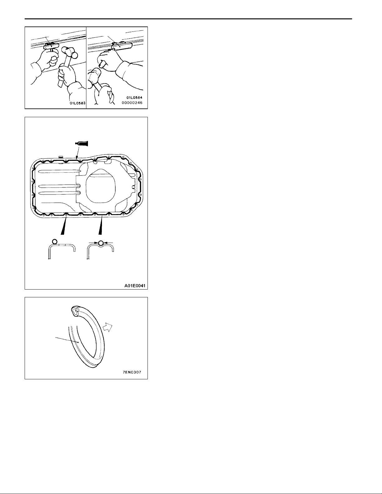
REMOVAL SERVICE POINT
AA" OIL PAN REMOVAL
INSTALLATION SERVICE POINTS
"AA OIL PAN INSTALLATION
1. Remove sealant from oil pan and cylinder block mating
surfaces.
2. Degrease the sealant-coated surface and the engine
mating surface.
3. Apply a continuous bead of the specified sealant to the
oil pan mating surface as shown.
Specified sealant:
MITSUBISHI GENUINE PART No. MD970389 or
equivalent
NOTE
The sealant should be applied in a continuous bead
approximately 4 mm in diameter.
4. Assemble oil pan to cylinder block within 15 minutes after
applying the sealant.
Caution
After installing the oil pan, wait at least 1 hour before
starting the engine.
Drain plug
gasket
"BA DRAIN PLUG GASKET INSTALLATION
Install a new gasket in the direction so that it faces as shown
in the illustration.
Oil pan
side
Page 14
ENGINE <4D5-Step III>-Timing Belt and Timing B
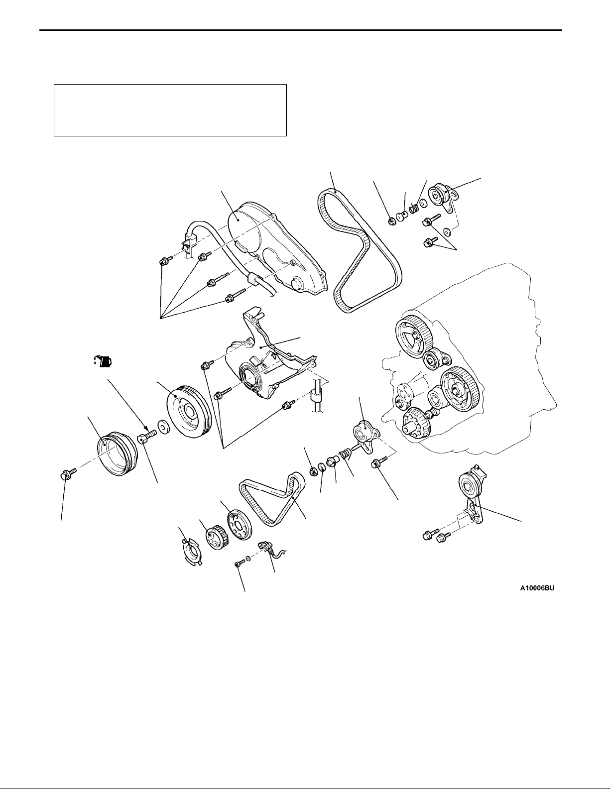
TIMING BELT AND TIMING BELT B
REMOVAL AND INSTALLATION
Pre-removal and Post-installation Operation
D Intercooler Removal and Installation
(Refer to GROUP 15.)
D Cooling Fan Removal and Installation.
11-7
(Engine oil)
3
11 ± 1 N·m
4
1
11 ± 1 N·m
5
26 ± 3 N·m
6
26 ± 3 N·m
18
8
9
7
26 ± 3 N·m
177 ± 9 N·m
26 ± 3 N·m
Removal steps
"CA 1. Timing belt front upper cover
2. Tension pulley and tension pulley
bracket assembly
3. Crankshaft pulley (for power steering and A/C)
AA""DA 4. Crankshaft pulley
"CA 5. Timing belt front lower cover
AB""BA 6. Timing belt
7. Tensioner spacer
8. Tensioner spring
11
13
12
9.0 ± 1.0 N·m
10
17
16
15
26 ± 3 N·m
14
9. Timing belt tensioner
10. Crank angle sensor
11. Crankshaft sensing blade
12. Crankshaft sprocket
13. Flange
AC""AA 14. Timing belt B
15. Gasket
16. Tensioner spacer B
17. Tensioner spring B
18. Timing belt tensioner B
2
Page 15
11-8
ENGINE <4D5-Step III>-Timing Belt and Timing B
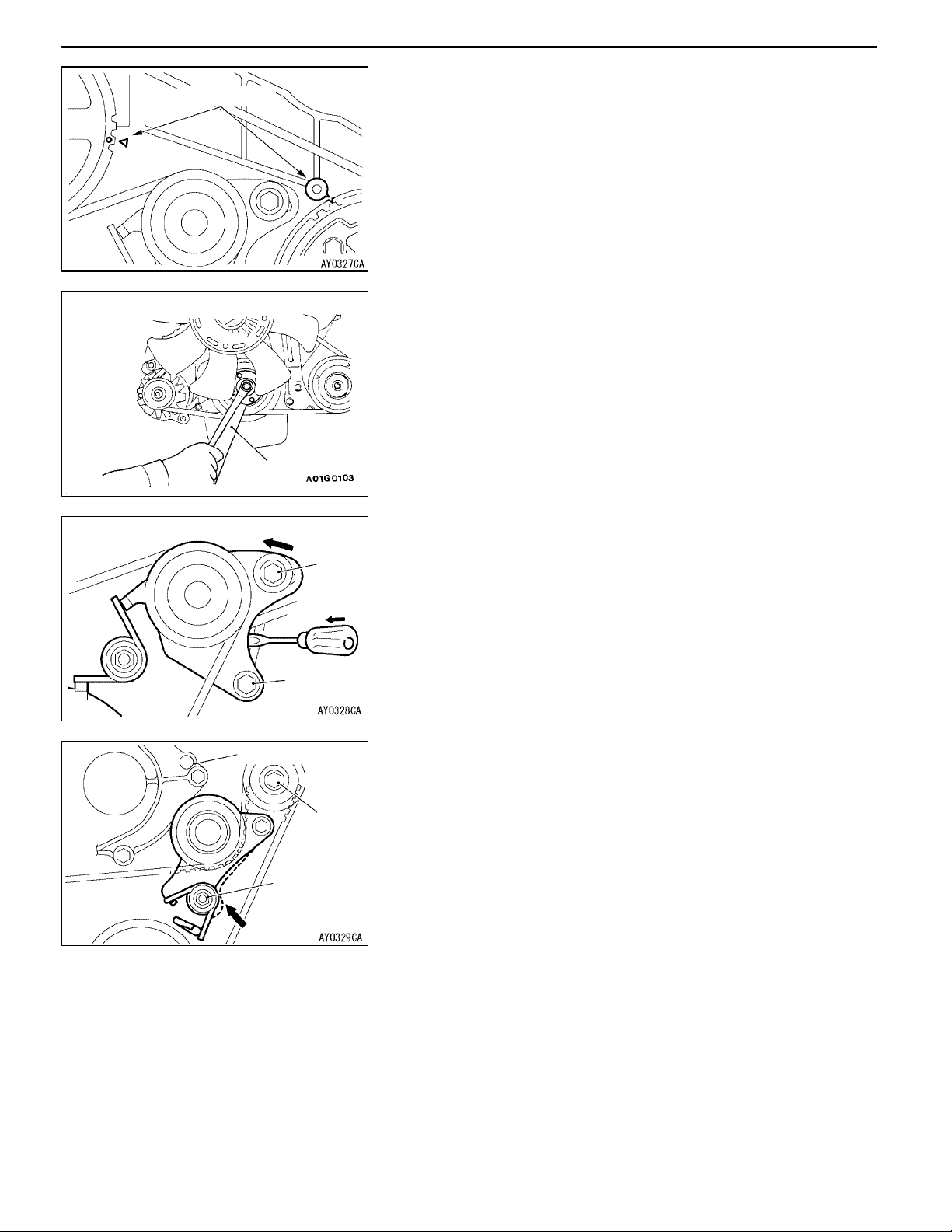
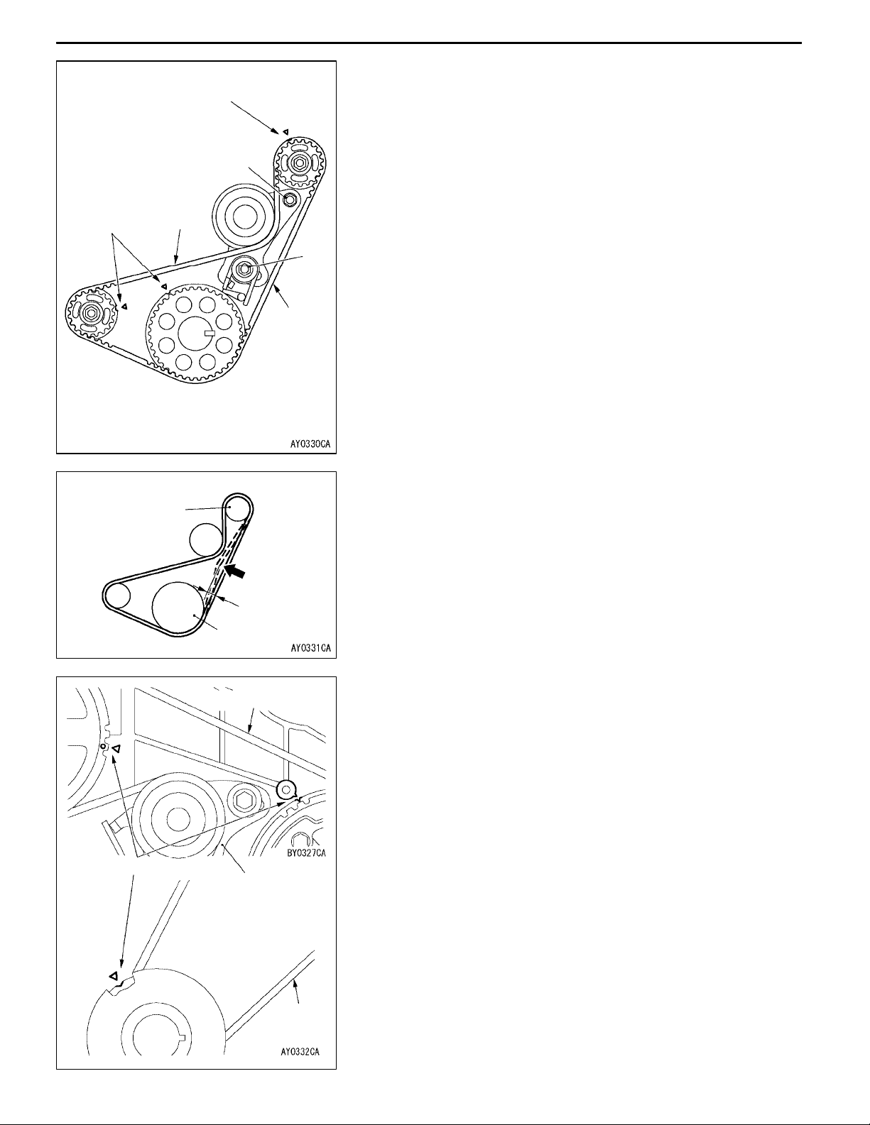
REMOVAL SERVICE POINTS
Timing marks
MD998721
AA" CRANKSHAFT PULLEY REMOVAL
1. Turn the crankshaft clockwise, align the timing marks
to set No.1 cylinder to TDC of its compression stroke.
Caution
Never turn the crankshaft anticlockwise.
2. Use the special tool to keep crankshaft from turning and
remove the bolts.
Tilt to water pump side
Water pump
D
AB" TIMING BELT REMOVAL
1. When reinstalling timing belt, mark an arrow at the belt
A
to show rotation direction.
2. Loosen the tensioner mounting bolt A and B.
3. Push timing belt tensioner to water pump side and tighten
the tensioner mounting bolt A and B. Secure so that
tensioner will not move back.
B
AC" TIMING BELT B REMOVAL
1. When reinstalling timing belt B, mark an arrow at the
belt to show rotation direction.
C
2. Loosen the tensioner mounting bolt C and nut D.
3. Push timing belt tensioner to water pump side and tighten
the tensioner mounting bolt C and nut D. Secure so that
tensioner will not move back.
Page 16
Timing
marks
ENGINE <4D5-Step III>-Timing Belt and Timing Belt BENGINE <4D5-Step III>-Timing Belt and Timing Belt B
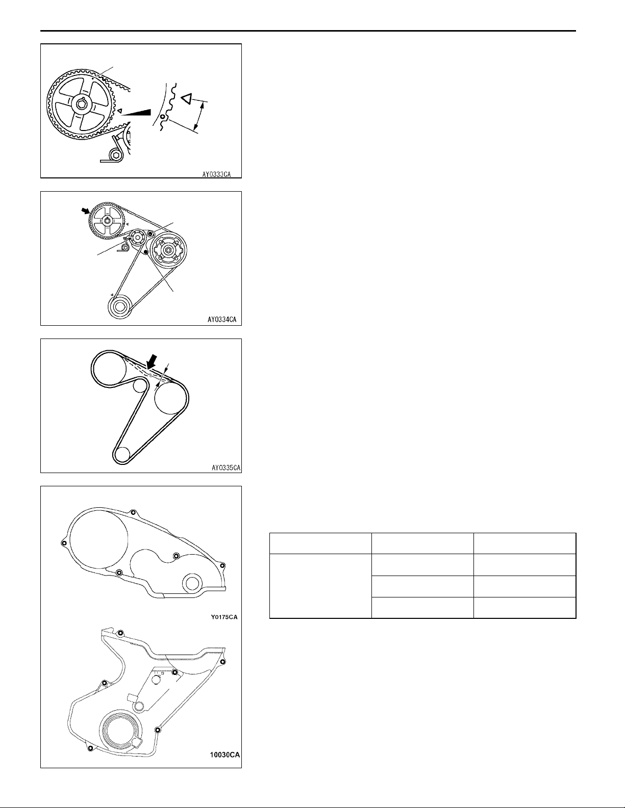
INSTALLATION SERVICE POINTS
Timing mark
C
Deflection
side
D
Tension
side
"AA TIMING BELT B INSTALLATION
1. Align the timing marks of the 3 sprockets.
2. When reusing timing belt B, make sure the arrow mark
is pointing in the same direction as when the belt was
removed.
3. Install timing belt B and make sure there is no deflection
on the tension side.
4. Press the deflection side of timing belt B with the hand
and fully stretch the tensioner side.
5. Make sure that the timing marks are aligned.
6. Loosen the tensioner mounting bolt and nut so that only
the pressure of the spring is applied to timing belt B.
7. Tighten the tensioner mounting bolt C and nut D, tightening
the nut first. If the bolt is tightened first, the tensioner
will move and tension the belt.
Tightening torque: 26 ± 3 N·m
11-9
Counterbalance
shaft sprocket
Timing marks
Belt deflection
Crankshaft
sprocket B
Tension side
Water pump
8. Press in the direction of the arrow in the figure with the
index finger to check the amount of deflection.
Standard value: 4 - 5 mm
"BA TIMING BELT INSTALLATION
1. Align the timing marks of the 3 sprockets.
2. When reusing timing belt, make sure the arrow mark is
pointing in the same direction as when the belt was
removed.
3. Install the timing belt to the crankshaft sprocket, to injection
pump sprocket, to tensioner and to camshaft sprocket
in that order. Being careful not to allow deflection on
the tension side of the timing belt.
Caution
(1) Engage the belt on the various sprockets while
maintaining tension on the belt of tension side.
(2) Align the injection pump sprocket with the timing
mark, hold the sprocket so that is does not turn
and engage the belt.
4. Loosen the tensioner mounting bolts and apply tension
with the spring.
Tension
side
Page 17
11-10
A
Tensioner
ENGINE <4D5-Step III>-Timing Belt and Timing Belt BENGINE <4D5-Step III>-Timing Belt and Timing Belt B
5. Turn the crankshaft clockwise and stop at the second
Camshaft sprocket
2 teeth
Tensioner
mounting bolt
Tensioner
mounting bolt
lobe of the camshaft sprocket.
Caution
(1) When turning the crankshaft in item (5), strictly
observe the specified amount of rotation (2 teeth
on the camshaft sprocket) in order to apply a
constant force to the tension side of the belt.
(2) Do not turn the crankshaft counterclockwise.
(3) Do not touch the belt during adjustment.
6. Make sure that the part indicated by arrow A does not
float upward.
7. Tighten the tensioner mounting bolts, starting with the
bolt in the elongated hole. If the lower bolt is tightened
first, belt tension will become too tight.
8. Turn the crankshaft anticlockwise and align the timing
mark. Next, make sure that the timing marks of all
sprockets are aligned.
Amount of belt
deflection
9. Press on the center of the bolt with an index finger to check
the amount of deflection.
Standard value: 4 - 5 mm
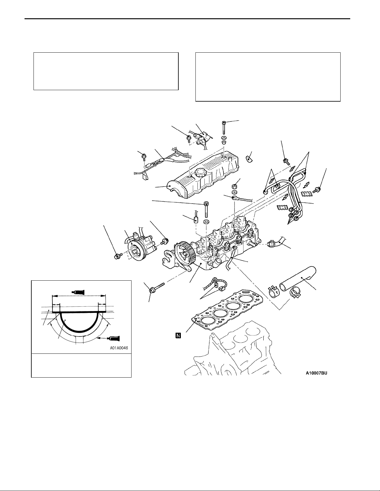
"CA TIMING BELT FRONT LOWER COVER/TIMING
A
BELT FRONT UPPER COVER INSTALLATION
Install the bolts to the timing belt cover at the shown positions.
A
C
B
A
Name Symbols Size mm (d×l)
Flange bolt A 6×22
B 6×50
C 6×60
d=Nominal diameter
l=Nominal length
A
B
A
"DA CRANKSHAFT PULLEY INSTALLATION
Using the special tool to install the crankshaft pulley as same
as removal procedure.
A
A
Page 18
ENGINE <4D5-Step III>-Cylinder Head Gasket
CYLINDER HEAD GASKET
REMOVAL AND INSTALLATION
11-11
Pre-removal Operation
D Intake and Exhaust Manifold Removal
(Refer to GROUP 15.)
D Timing Belt Removal (Refer to P.11-4.)
D Engine Coolant Draining.
13 ± 2 N·m
10 ± 2 N·m
29 ± 2 N·m → +120°
(During cold engine)
22 ± 4 N·m
22 ± 4 N·m
12
10
Post-installation Operation
D Timing Belt Installation (Refer to P.11-4.)
D Intake and Exhaust Manifold Installation
(Refer to GROUP 15.)
D Fuel Line Air Bleeding
(Refer to GROUP 13 - On-vehicle Service.)
D Engine Coolant Filling
8
9
5.9 ± 1.0 N·m
4.9 ± 1.0 N·m
11
30 ± 6
N·m
4.9 ± 1.0
N·m
30 ± 6 N·m
4.9 ± 1.0 N·m
3
5
2
30 ± 6 N·m
10 mm
10 mm
10
11
Sealant:
3M ATD Part No. 8660 or
equivalent
Removal steps
1. Engine coolant temperature switch
connector (for A/C)
2. Engine coolant temperature gauge
unit and sensor connector
3. Glow plug terminal
AA""DA 4. Radiator upper hose
AB""CA 5. Fuel injection pipe
6. Heater hose or water by-pass hose
connection
7. Fuel hose connection
6
7
13
14
4
1
24 ± 4 N·m
15
8. Boost sensor and bracket assembly
9. Vacuum hose and pipe assembly
10. Rocker cover
11. Semi-circular packing
AC" 12. Power steering oil pump assembly
13. Power steering oil pump bracket
bolt
AD""BA 14. Cylinder head assembly
"AA 15. Cylinder head gasket
Page 19
11-12
ENGINE <4D5-Step III>-Cylinder Head Gasket
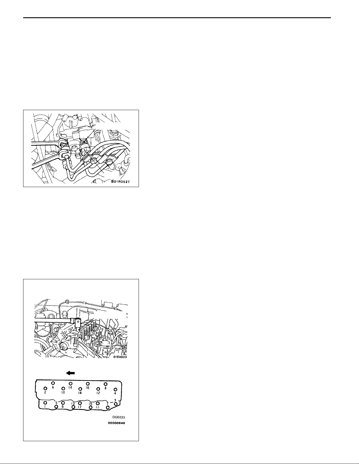
REMOVAL SERVICE POINTS
AA" RADIATOR UPPER HOSE DISCONNECTION
After making mating marks on the radiator upper hose and
the hose clamp, disconnect the radiator upper hose.
AB" FUEL INJECTION PIPE REMOVAL
Delivery holder
Nut
When loosening nuts at both ends of injection pipe, hold
the delivery holder (for pump side) and the injection nozzle
assembly (for nozzle side) with wrench and loosen nut.
Caution
After disconnecting the injection pipe, plug the opening
so that no foreign particles get inside the pump or into
the injection nozzle.
MD998051
AC" POWER STEERING OIL PUMP REMOVAL
Remove the power steering oil pump from the bracket with
the hose attached.
NOTE
Place the removed power steering oil pump in a place where
it will not be a hindrance when removing and installing the
engine assembly, and tie it with a cord.
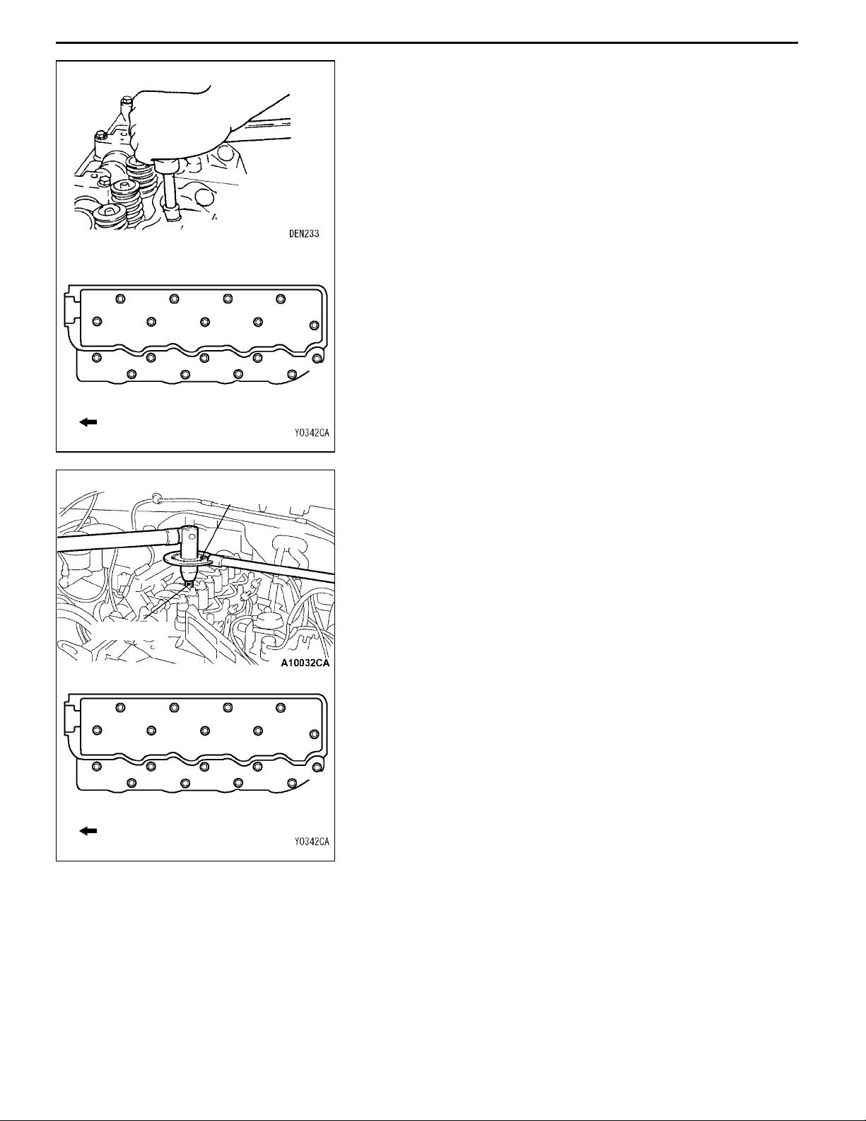
AD" CYLINDER HEAD ASSEMBLY REMOVAL
Use the special tool to tighten each bolt 2 - 3 times in the
order shown in the illustration.
Front
Page 20
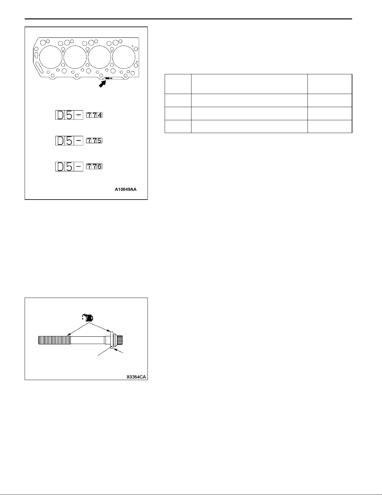
Identification mark
ENGINE <4D5-Step III>-Cylinder Head Gasket
INSTALLATION SERVICE POINTS
"AA CYLINDER HEAD GASKET INSTALLATION
When replacing the cylinder head gasket only, confirm the
gasket identification mark, and then select a replacement
part according to the table below:
Spec Identification mark (size) Parts num-
A D5 -774 (fitted thickness 1.45 ± 0.04) MD377774
11-13
ber
A
B
B D5 -775 (fitted thickness 1.50 ± 0.04) MD377775
C D5- 776 (fitted thickness 1.55 ± 0.04) MD377776
Caution
The thickness of the original cylinder head gasket is
selected according to the protrusion amount of the piston.
C
Therefore, if the piston or the connecting rod is replaced,
the protrusion amount may be changed. Always select
a correct gasket by measuring the protrusion amount.
(For details, refer to the Engine Workshop Manual.)
"BA CYLINDER HEAD INSTALLATION
1. Select a cylinder head gasket of correct specification.
2. Clean the cylinder head assembly and the cylinder block
mating surfaces with a scraper or a wire brush.
Caution
Do not allow foreign material to enter the engine
coolant or oil passages and the cylinder.
Cylinder head
bolt washer
3. Install the cylinder head bolt washer to the cylinder head
bolt so that the washer chamfered side faces as shown.
4. Apply a small amount of engine oil to the cylinder head
bolt thread and the washer.
Chamfered
side
Page 21
11-14
ENGINE <4D5-Step III>-Cylinder Head Gasket
5. Tighten the cylinder head bolts according to the following
procedure (angle-tightening procedure.)
(1) Use the special tool to tighten the cylinder head bolts
in the order of the illustrated numbers to 29 ± 2 N·m.
MD998051
13
13
14
14
9
10
9
10
17
18
Front of engine
MD998051
17
18
5
6
3
1
2
11
7
4
8
12
15
16
(2) Place the special tool in a wrench to tighten the
MB991614
cylinder head bolt in the order of the illustrated
numbers to 120_.
"CA FUEL INJECTION PIPE INSTALLATION
When tightening the nuts at both ends of the fuel injection
pipe, hold the delivery holder (for pump side) and the injection
nozzle assembly (for nozzle side) with a wrench, and tighten
the nuts to the specified torque.
Tightening torque: 30 ± 6 N·m
"DA RADIATOR UPPER HOSE CONNECTION
5
3
1
11
7
15
To reuse the radiator upper hose, align the mating marks
that were made during removal, and then install the hose
clamp.
6
4
2
12
8
16
Front of engine
Page 22
LUBRICATION - General/Lubricant
It
4D5-St
III
12-1
GROUP 12
LUBRICATION
GENERAL
OUTLINE OF CHANGE
D The engine oil quantity has been changed as variable geometry (VG) turbocharger has been used.
LUBRICANT
ems
Engine oil quantity L Oil filter 0.8
Oil cooler 0.4
Total 7.5
ep
Page 23

NOTES
Page 24

FUEL
CONTENTS
13-1
FUEL SYSTEM <4D5-step III>2.......
GENERAL 2.................................
Outline of Changes 2...........................
GENERAL INFORMATION 2...................
SERVICE SPECIFICATIONS 5.................
SEALANT 5..................................
SPECIAL TOOLS 5...........................
TROUBLESHOOTING 7.......................
ON-VEHICLE SERVICE 57....................
Injection Timing Check and Adjustment 57.........
Idle Speed Check and Adjustment 57.............
Injection Nozzle Check and Adjustment 57.........
Accelerator Pedal Position Sensor (APS)
Adjustment 58.................................
Control Relay Continuity Check 59................
Accelerator Pedal Position Sensor (APS)
Check 59......................................
Idle Switch Check 60............................
Boost Air Temperature Sensor (Intake Air
Temperature Sensor) Check 60..................
Engine Coolant Temperature Sensor Check 61.....
EGR Valve Position Sensor Check 61.............
Fuel Injection Pump Check 62....................
Throttle Solenoid Valve Check 63.................
Throttle Actuator Check 64......................
Variable Geometry Solenoid Valve Check 64.......
EGR Control Solenoid Valve Check 64............
FUEL INJECTION PUMP 65..................
CRANKSHAFT POSITION SENSOR 66........
ACCELERATOR PEDAL 67...................
Page 25

13-2
FUEL SYSTEM <4D5-step III> - General/General Information
FUEL SYSTEM <4D5-step III>
GENERAL
OUTLINE OF CHANGES
Some service procedures have been established as the following changes have been made due to the
compliance with the Emission Regulation Step III.
D An electronic-controlled fuel injection pump has been used.
D A crankshaft position sensor has been used as the electronic-controlled fuel injection pump has been
used.
D An engine-ECU has been used as the electronic-controlled fuel injection pump has been used.
Removal and installation procedure of the engine-ECU is the same as for vehicles with 4G6 engine
or 6G7 engine.
D Due to the introduction of the electronic-controlled injection pump, the accelerator cable has been
abolished, and the accelerator pedal position sensor has been added.
GENERAL INFORMATION
The electronically-controlled fuel injection system consists of sensors which detect the condition of the
diesel engine, an engine-ECU which controls the system based on signals from these sensors, and actuators
which operate according to control commands from the engine-ECU.
The engine-ECU carries out operations such as fuel injection rate control, fuel injection timing control
and idle up control. In addition, the engine-ECU is equipped with several self-diagnosis functions which
make troubleshooting easier in the event that a problem develops.
FUEL INJECTION RATE CONTROL
The fuel injection completion timing is controlled by means of a solenoid-type spill valve to ensure that
the optimum amount of fuel is supplied to the engine in accordance with gradual changes in the engine
running condition.
Before fuel injection starts, the solenoid-type spill valve is on (energized), so that the valve is closed.
As the plunger turns and rises, fuel is sent out under pressure, and when the fuel flow rate reaches
the target value for fuel injection, the solenoid-type spill valve turns off. When the solenoid-type spill
valve turns off, the fuel under high pressure inside the plunger is leaked out into the pump chamber
and fuel injection is completed.
FUEL INJECTION TIMING CONTROL
The position of the injection pump timer piston is controlled so that fuel injection is carried out at the
optimum timing in accordance with the engine running condition.
The timer piston position is determined by duty control of the timing control solenoid valve which is located
in the line between the high-pressure chamber and the low-pressure chamber of the timer piston.
The fuel injection timing is advanced by increasing the control duty of the timing control solenoid valve.
IDLE SPEED CONTROL
Controlling the fuel injection rate in accordance with the engine running condition maintains the idle speed
at the optimum condition.
Page 26

FUEL SYSTEM <4D5-step III> - General Information
SELF-DIAGNOSIS FUNCTION
D When an abnormality is detected in any of the sensors or actuators, the engine warning lamp illuminates
to warn the driver.
D When an abnormality is detected in any of the sensors or actuators, a diagnosis code number
corresponding to the problem which occurred is output.
D The RAM data relating to the sensors and actuators which is stored in the engine-ECU can be read
using the MUT-II. In addition, the actuators can be force-driven under certain conditions.
OTHER CONTROL FUNCTIONS
1. Power Supply Control
When the ignition switch is turned to ON, the relay turns on and power is supplied to components
such as the timing control solenoid valve.
2. Intake Air Throttle Control
When the engine-ECU detects an abnormality in any of the sensors or actuators, the throttle valve
is half opened to restrict the amount of intake air in order to prevent the vehicle from running away.
3. A/C Relay Control
Turns the compressor clutch of the A/C ON and OFF
4. Condenser Fan Motor Relay Control
Controls the condenser fan motor relay based on the A/C switch, engine coolant temperature and
vehicle speed input signals.
5. Intercooler Fan Motor Relay Control
Controls the intercooler fan motor relay based on the boost air temperature and vehicle speed input
signals.
6. Glow Control
Refer to GROUP 16.
7. EGR Control
Refer to GROUP 17.
13-3
Page 27
13-4
FUEL SYSTEM <4D5-step III> - General Information
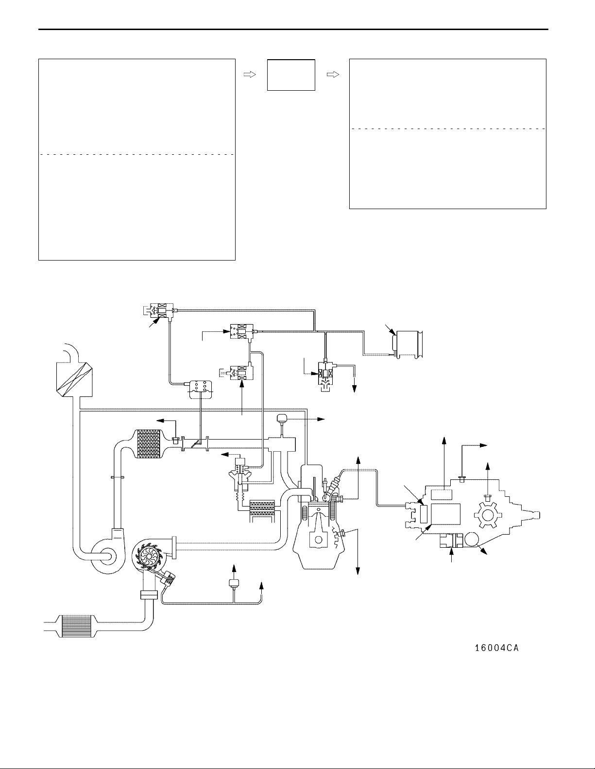
CONTROL SYSTEM DIAGRAM
L1. Pump speed sensor
L2. Crank angle sensor
L3. Engine coolant temperature sensor
L4. Boost pressure sensor
L5. Fuel temperature sensor
L6. Boost air temperature sensor
L7. Control sleeve position sensor
L8. Timer piston position sensor
L9. EGR valve position sensor
L10. Variable geometry control pressure sensor
D Accelerator pedal position sensor (main)
D Accelerator pedal position sensor (sub)
D Idle switch
D Power supply
D Ignition switch-IG
D Ignition switch-ST
D Vehicle speed sensor
D A/C switch
D A/C relay switch
D Injection volume adjusting ROM
D Barometric pressure sensor (ECU built-in)
l5 Throttle solenoid valve
3
l
EGR control
solenoid valve No. 1
Throttle
actuator
EngineECU
7
l
Variable geometry
solenoid valve
l1. GE actuator (electronic governor)
l2. Timing control valve
l3. EGR control solenoid valve No. 1
l4. EGR control solenoid valve No. 2
l5. Throttle solenoid valve
l6. Fuel cut solenoid valve
l7. Variable geometry solenoid valve
D Control relay
D A/C relay
D Condenser fan relay
D Intercooler fan relay
D Glow indicator lamp
D Glow plug relay
D Engine warning lamp
D Diagnosis output
Vacuum pump
Alternator
6 Boost air
L
temperature sensor
Catalytic converter
L9 EGR
valve position
sensor
EGR valve
Variable geometry
turbocharger
Variable
geometry
actuator
4 EGR control
l
solenoid
valve No. 2
L10 Variable geometry control
pressure sensor
To variable geometry solenoid valve
To variable
geometry actuator
L4 Boost pressure
sensor
L3 Engine coolant
temperature sensor
l6 Fuel cut
l1 GE actuator
L2 Crank angle
sensor
L7 Control
sleeve
position
sensor
solenoid
valve
l2 Timing control
valve
L5 Fuel
temperature
sensor
L1 Pump speed
sensor
L8 Timerpiston
position
sensor
Page 28

FUEL SYSTEM <4D5-step III>-Service Specifications/Sealant/Special Tools
p(p
g
p
p
p
p
SERVICE SPECIFICATIONS
Item Standard value
Fuel injection initial pressure kPa 14,710 - 15,490
Accelerator pedal position sensor reference voltage V 0.985 - 1.085
Accelerator pedal position sensor resistance kΩ 3.5 - 6.5
Boost air temperature sensor (Intake air temperature
sensor) resistance kΩ
Engine coolant temperature sensor resistance kΩ
Fuel cut solenoid valve resistance Ω 6.8 - 9.2
Timing control valve resistance Ω 10.8 - 11.2
Timer piston position sensor resistance Ω
Control sleeve position sensor resistance Ω
GE actuator (electronic governor) resistance Ω Connector terminals No. 6 - No. 10 0.64 - 0.72
Fuel temperature sensor resistance kΩ Connector terminals No. 7 - No. 11 1.4 - 2.6
Pump speed sensor resistance kΩ 1.36 - 1.84
Throttle solenoid valve resistance Ω 36 - 44
When the temperature is 20_C 2.3 - 3.0
When the temperature is 80_C 0.30 - 0.42
When the temperature is 20_C 2.1 - 2.7
When the temperature is 80_C 0.26 - 0.36
Connector terminals No. 1 - No. 2 160 - 168
Connector terminals No. 1 - No. 3 80 - 84
Connector terminals No. 2 - No. 3 80 - 84
Connector terminals No. 4 - No. 12 11.2 - 12.4
Connector terminals No. 4 - No. 8 5.6 - 6.2
Connector terminals No. 8 - No. 12 5.6 - 6.2
13-5
SEALANT
Item Specified sealant
Engine coolant temperature sensor 3M Nut Locking Part No. 4177 or equivalent
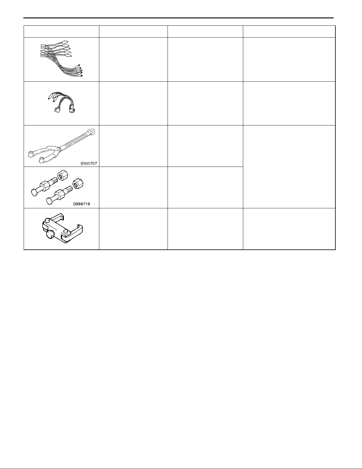
SPECIAL TOOL
Tool Number Name Use
MB991502 MUT-II sub
assembly
MB991529 Diagnosis code
check harness
MB991348 Test harness set D Boost pressure sensor check
Electronically controlled fuel injection system check
Diagnosis code reading
D Variable geometry control
pressure sensor check
Page 29
13-6
Tool UseNameNumber
FUEL SYSTEM <4D5-step III> - Special Tools
MB991658 Test harness set D APS adjustment
D Inspection using an analyzer
MD998478 Test harness
(3-pin, square)
MB990767 End yoke holder Holding the fuel injection pump
MD998719 Crankshaft pulley holder
pin
MD998388 Injection pump sprocket
puller
D Crank angle sensor check
D Inspection using an analyzer
sprocket
Fuel injection pump sprocket
removal
Page 30
FUEL SYSTEM <4D5-step III> - Troubleshooting
Engine warning lamp
(check engine lamp)
13-7
TROUBLESHOOTING
STANDARD FLOW OF DIAGNOSTIC
TROUBLESHOOTING
Refer to GROUP 00 - How to Use Troubleshooting/Inspection
Service Points.
NOTE
When replacing the engine-ECU, replace immobilizer-ECU
and ignition key as well at the same time.
DIAGNOSIS FUNCTION
ENGINE WARNING LAMP (CHECK ENGINE LAMP)
Engine warning lamp is lit when any abnormality takes place
in the item related to electronically controlled fuel injection
system shown in the following table.
If the malfunction indicator lamp has been on and/or is lit
when the engine is in operation, check the diagnosis output.
Engine warning lamp check items
Accelerator pedal position sensor (main)
Accelerator pedal position sensor (sub)
Boost pressure sensor (Boost sensor)
Crank angle sensor
Control sleeve position sensor
Timer piston position sensor
Throttle solenoid valve
GE actuator
Variable geometry control pressure sensor
Barometric pressure sensor
Timing control valve
Idle switch
Engine-ECU
METHOD OF ERASING AND ERASING DIAGNOSIS
CODES
Refer to GROUP 00 - How to Use Troubleshooting/Inspection
Service Points.
INSPECTION USING MUT-II DATA LIST AND
ACTUATOR TESTING
1. Carry out inspection by means of the data list and the
actuator test function.
If there is an abnormality, check and repair the chassis
harnesses and components.
2. After repairing, re-check using MUT-II and check that
the abnormal input and output have returned to normal
as a result of the repairs.
3. Erase the diagnosis code memory.
4. Remove the MUT-II.
5. Start the engine again and carry out a road test to confirm
that the problem has disappeared.
Page 31

13-8
FUEL SYSTEM <4D5-step III> - Troubleshooting
FAIL-SAFE, BACKUP FUNCTIONS
When abnormalities in the major sensors are detected by diagnosis functions, pre-set control logic operates
to maintain a safe driving condition for the vehicle.
Diagnosis item Control features in malfunction
Accelerator pedal position sensor D Accelerator pedal released (idle switch ON)
Acceleration opening degree = 0 %
D Accelerator pedal applied (idle switch OFF)
Engine controlled at low speed
Acceleration opening degree = 30 % fixed
D Void EGR control
Idle switch Void idling speed control.
Engine speed sensor D Engine controlled at low speed
D Void EGR control
D Void variable geometry turbocharger control
Boost air temperature sensor D Maintain the intake air temperature at 50_C.
D Void EGR control
Vehicle speed sensor D Void idling speed control.
D Void EGR control
Engine coolant temperature sensor D Maintain the engine coolant temperature at 80_C (However, the system
assumes the coolant temperature as 0_C when engine is started.).
D Void EGR control
Control sleeve position sensor D Engine controlled at low speed
D Void EGR control
D Void variable geometry turbocharger control
Timer piston position sensor D Injection timing stabilizing control
D Void EGR control
Barometric pressure sensor (ECU
built-in)
Fuel temperature sensor Maintain the fuel temperature at 40_C.
Boost pressure sensor D Keep the boost pressure as barometric pressure (101 kPa).
Injection volume adjusting ROM Void correction.
GE actuator D Engine controlled at low speed
Over boost D Void variable geometry turbocharger control
Timing control valve D Injection timing stabilizing control
EGR valve position sensor Void EGR control
Variable geometry control pressure
sensor
D Keep the barometric pressure at 101 kPa.
D Void EGR control
D Void variable geometry turbocharger control
D Void EGR control
D Void variable geometry turbocharger control
D Void EGR control
D Void variable geometry turbocharger control
D Engine controlled at low fuel injection
D Void EGR control
D Void EGR control
D Void variable geometry turbocharger control
Page 32

FUEL SYSTEM <4D5-step III> - Troubleshooting
INSPECTION CHART FOR DIAGNOSIS CODES
Code No. Diagnosis item Reference
page
11 Accelerator pedal position sensor (main) system 13-10
12* Boost pressure sensor system 13-11
13 Barometric pressure sensor (ECU built-in) system 13-12
14 Fuel temperature sensor system 13-12
15 Engine coolant temperature sensor system 13-13
16 Boost air temperature sensor system 13-13
17 Vehicle speed sensor system 13-14
18 Pump speed sensor system 13-15
21 Crank angle sensor system 13-16
23 Idle switch (accelerator pedal position sensor built-in) system 13-17
25* Timer piston position sensor system 13-18
26* Control sleeve position sensor system 13-19
27 Accelerator pedal position sensor (sub) system 13-20
41* Throttle solenoid valve system 13-21
43 Timing control valve system 13-22
46 Injection volume adjusting ROM system 13-23
48* GE actuator (in the middle of control sleeve position sensor inoperative) system 13-24
49* Over boost (variable geometry control pressure sensor system malfunction) 13-25
51 EGR valve position sensor system 13-26
52 Variable geometry control pressure sensor system 13-27
54 Immobilizer system 13-28
13-9
Caution
If the above-mentioned diagnosis code number with the asterisks can be displayed along with another
code number in parentheses simultaneously, check the other code number before replacing the
engine-ECU.
12 (41, 49), 26 (48), 25 (43), 41 (12, 49), 48 (26), 49 (12, 41)
Page 33

13-10
FUEL SYSTEM <4D5-step III> - Troubleshooting
INSPECTION PROCEDURE FOR DIAGNOSIS CODE
Code No. 11 Accelerator pedal position sensor (main)
system
Range of Check
D Ignition switch: ON, accelerator pedal position sensor (sub) operative, except
for during engine cranking
Set Conditions
D Accelerator pedal position sensor output voltage is as below for 1 second:
Sub side: 0.2 V or more, less than 2.5 V
Main side: 4.5 V or more
or
Sub or main side: less than 0.2 V
Range of Check
D Ignition switch: ON, except for during engine cranking
Set Conditions
D The output voltage of accelerator pedal position sensor (main and sub) for
0.2 second is 0.2 V or higher, or lower than 4.5 V and the difference in
sensor output voltage between the main and sub is 1 V or higher, or idle
switch: ON, and sensor main output voltage is 1.875 V or higher.
Accelerator pedal position sensor check
(Refer to P.13-59.)
OK
Measure at C-134 accelerator pedal position
sensor connector
D Disconnect the connector and measure
at the harness side.
D Voltage between 2 and earth
(Ignition switch: ON)
OK: 4.5 - 5.5 V
D Continuity between 1 and earth
OK: Continuity
OK
NG
NG
Replace
Check the following connector: C-43
Check the trouble symptoms.
Check the harness between the
engine-ECU and the accelerator pedal
position sensor connector.
Replace the engine-ECU.
Probable cause
D Accelerator pedal position sensor inoperative
D Accelerator pedal position sensor open circuit,
short circuit, or connector contact inoperative
D Engine-ECU inoperative
NG
OK
NG
NG
OK
Repair
Repair
Measure at C-43 engine-ECU connector
D Connect the connector.
D Voltage between 84 and the earth
(Ignition switch: ON)
OK: 0.9 - 1.1 V
(Throttle lever idling position)
4.1 V or higher
(Throttle lever fully opened position)
OK
Check the following connector: C-43
OK
Check the trouble symptoms.
Check the harness between the
engine-ECU and the accelerator pedal
position sensor connector.
OK
Replace the engine-ECU.
NG
NG
NG
NGNGNGNGNG
NG
Check the following connectors:
C-43, C-134
OK
Check the trouble symptoms.
NG
Replace the engine-ECU.
Repair
Repair
NG
Repair
Page 34

FUEL SYSTEM <4D5-step III> - Troubleshooting
13-11
Code No. 12 Boost pressure sensor (boost sensor)
system
Range of Check
D Ignition switch: ON, except for during engine cranking
Set Conditions
D Sensor output voltage for 1 second is 4.5 V or higher
(boost pressure is approximately 267 kPa).
or
D Sensor output voltage for 1 second is 0.2 V or lower
(boost pressure is approximately 51.7 kPa or lower)
Range of Check
D Engine speed is 2,000 r/min or higher, barometric pressure is 69.7 kPa or
less (equivalent to an altitude of 300 m) and under high load.
Set Conditions
D Boost pressure is lower than the barometric pressure + 13 kPa for 3
seconds.
Measure at A-129 boost pressure
sensor connector
D Connect the connector.
(Test harness: MB991348 used)
D Voltage between 1 and the earth
(Engine: Idling)
OK: 1.3 - 1.7 V
D Voltage between 1 and the earth
OK: When the accelerator pedal
is suddenly pressed from
the idling condition, the
voltage temporarily increases from 1.3 V to 1.7
V.
OK
NG
Measure at A-129 boost pressure
sensor connector
D Disconnect the connector and
measure at the harness side.
D Voltage between 3 and the earth
(Ignition switch: ON)
OK: 4.5 - 5.5 V
D Continuity between 2 and the
earth
OK: Continuity
OK
Check the following connector:
A-129
OK
Probable cause
D Boost pressure sensor inoperative
D Boost pressure sensor open circuit, short circuit,
or connector contact inoperative
D Boost pressure sensor hose disconnected
D Engine-ECU inoperative
NG
NG
Checkthefollowing connector:C-130
OK
NG
Check the trouble symptoms.
NG
Check the harness between the
engine-ECU and the boost pressure
sensor connector.
NG
Repair
Replace the engine-ECU.
OK
Repair
Repair
Measure at C-43 engine-ECU
connector
D Connect the connector.
D Voltage between 85 and the
earth (Engine: Idling)
OK: 1.3 - 1.7 V
OK
Check the following connector:
C-43
NG
OK
Check the trouble symptoms.
NG
Replace the engine-ECU.
NG
Repair
Check the trouble symptoms.
NG
Check the harness between the
engine-ECU and the boost pressure
sensor connector.
OK
Check the vacuum hose between the
boost pressure sensor and the intake
manifold.
OK
Replace the boost pressure sensor.
Check the following connector:
A-129
OK
Check the trouble symptoms.
NG
Check the harness between the
engine-ECU and the boost pressure
sensor connector, and repair if
necessary.
NG
NG
NG
Repair
Repair
Repair
Page 35

13-12
FUEL SYSTEM <4D5-step III> - Troubleshooting
Code No. 13 Barometric pressure sensor system Probable cause
Range of Check
D Ignition switch: ON, except for during engine cranking
Set Conditions
D The sensor output voltage is for 3 seconds is 4.5 V or higher (the
barometric pressure is approximately 114 kPa or over).
or
D The sensor output voltage is for 3 seconds is 1.5 V or lower (the barometric
pressure is approximately 40 kPa or under).
Range of Check
D Ignition switch: ON
D The coolant temperature is 40_C or lower
Set conditions
D Difference between the barometric pressure and boost pressure sensors is
13.3 kPa or more
Engine-ECU inoperative
Check the trouble symptoms.
NG
Replace the engine-ECU.
Code No. 14 Fuel temperature sensor system Probable cause
Range of Check
D Ignition switch: ON, except for during engine cranking
Set Conditions
D The sensor output voltage for 3 seconds is 0.2 V or lower (the fuel
temperature is approximately 125°C or higher).
or
D The sensor output voltage for 3 seconds is 4.6 V or higher (the fuel
temperature is approximately - 47°C or lower).
Fuel temperature sensor check (Refer to
P.13-62.)
OK
Measure at A-131 fuel temperature sensor
connector
D Disconnect the connector and measure at
the harness side.
D Voltage between 11 and the earth
(Ignition switch: ON)
OK: 4.5 - 5.5 V
D Continuity between 7 and the earth
OK: Continuity
OK
Check the following connector: A-131
OK
Check the trouble symptoms.
NG
Repair
NG
NG
NG
Replace the injection pump.
Check the following connectors:
C-43, C-130
Check the trouble symptoms.
Check the harness between the
engine-ECU and the fuel temperature
sensor connector.
Replace the engine-ECU.
Replace the engine-ECU.
D Fuel temperature sensor inoperative
D Fuel temperature sensor open circuit, short circuit,
or connector contact inoperative
D Engine-ECU inoperative
NG
OK
NG
NG
OK
Repair
Repair
Page 36

FUEL SYSTEM <4D5-step III> - Troubleshooting
Code No. 15 Engine coolant temperature sensor system Probable cause
Range of Check
D Ignition switch: ON, except for during engine cranking
Set Conditions
D The sensor output voltage for 3 seconds is 4.9 V or higher (the coolant
temperature is approximately - 45_C or lower).
or
D The sensor output voltage for 3 seconds is 0.2 V or lower (the coolant
temperature is approximately 140_C or higher).
D Engine coolant temperature sensor inoperative
D Engine coolant temperature sensor open circuit,
short circuit, or connector contact inoperative
D Engine-ECU inoperative
13-13
Engine coolant temperature sensor check
(Refer to P.13-60.)
OK
Measure at A-113 engine coolant temperature
sensor connector
D Disconnect the connector and measure at
the harness side.
D Voltage between 1 and the earth
(Ignition switch: ON)
OK: 4.1 - 4.9 V
D Continuity between 2 and the earth
OK: Continuity
OK
Check the following connector: A-113
OK
Check the trouble symptoms.
NG
Repair
NG
NG
NG
Replace
Check the following connectors:
C-43, C-130
Check the trouble symptoms.
Check the harness between the
engine-ECU and the engine coolant
temperature sensor connector.
Replace the engine-ECU.
Replace the engine-ECU.
Code No. 16 Boost air temperature sensor (intake air
sensor) system
Range of Check
D Ignition switch: ON, except for during engine cranking
Set Conditions
D The sensor output voltage for 3 seconds is 4.6 V or higher (the intake air
temperature is approximately - 45_C or lower).
or
D The sensor output voltage for 3 seconds is 0.3 V or lower (the intake air
temperature is approximately 110_C or higher).
NG
OK
NG
NG
OK
Repair
Repair
Probable cause
D Boost air temperature sensor inoperative
D Boost air temperature sensor open circuit, short
circuit, or connector contact inoperative
D Engine-ECU inoperative
Boost air temperature sensor check
(Refer to P.13-60.)
OK
Measure at C-136 boost air temperature
connector
D Disconnect the connector and measure at
the harness side.
D Voltage between 1 and the earth
(Ignition switch: ON)
OK: 4.0 - 5.3 V
D Continuity between 2 and the earth
OK: Continuity
OK
Check the following connector: C-136
OK
Check the trouble symptoms.
NG
Repair
NG
NG
NG
Replace
Check the following connectors:
C-43, C-130
OK
Check the trouble symptoms.
NG
Check the harness between the
engine-ECU and the boost air temperature
sensor connector.
OK
Replace the engine-ECU.
Replace the engine-ECU.
NG
NG
Repair
Repair
Page 37

13-14
FUEL SYSTEM <4D5-step III> - Troubleshooting
Code No. 17 Vehicle speed sensor system Probable cause
Range of Check
D Ignition switch: ON
D Engine speed: 2,800 r/min or higher
D Driving with heavy load
Set Conditions
D Slower than vehicle speed of 3 km/h
D Vehicle speed sensor inoperative
D Vehicle speed sensor open circuit, short circuit, or
connector contact inoperative
D Engine-ECU inoperative
Check the vehicle speed sensor.(Refer toGROUP54-Combination
Meters.)
OK
Measure at combination meter connector C-05, C-06.
D Disconnect the connector and measure at the harness side.
1. Voltage between 1 and earth (Ignition switch: ON)
OK: 4.8 - 5.2 V
2. Continuity between 43 and earth
OK: Continuity
OK
Check the following
connectors:
C-05, C-06
OK
Check trouble symptom.
NG
Check the harness wire
between the engine-ECU
and the combinationmeter
connector.
OK
Replace the engine-ECU.
NG
NG
Repair
Repair
NG
1. NG
2. NG
Replace
Check the following
connector:
C- 75, C-24, C-43
OK
Check trouble symptoms.
NG
Check the harness wire
betweentheengine-ECU
and the combination meter connector.
OK
Replace the engine-ECU.
Check the harness wire between the combination meter and the
earth, and repair if necessary.
NG
NG
Repair
Repair
Page 38

FUEL SYSTEM <4D5-step III> - Troubleshooting
Code No. 18 Pump speed sensor system Probable cause
Range of Check
D Ignition switch: ON
D Not during the engine cranking
Set Conditions
D The difference between the pump speed sensor and the crank angle sensor
output value is 500 r/min or higher for 4 seconds
D Malfunction of pump speed sensor
D Open circuit or short-circuit in pump speed sensor
circuit, or poor sensor contact
D Engine-ECU inoperative
13-15
Pump speed sensor check (Refer to
P.13-63.)
OK
Measure at engine-ECU connector C-130.
D Connect the connector.
D Voltage between 51 - 61.
(Engine: idling and then raced)
OK: Voltage increases from the voltage
when engine is idling
OK
Check the following connector: C-130
OK
Check trouble symptoms.
NG
Replace the engine-ECU.
NG
NG
NG
Repair
Replace the injection pump.
Check the following connector:
A-133, C-130
OK
Check the trouble symptoms.
NG
Check the harness between the
engine-ECU and the pump speed sensor
connector, and repair if necessary.
NG
Repair
Page 39

13-16
FUEL SYSTEM <4D5-step III> - Troubleshooting
Code No. 21 Crank angle sensor system Probable cause
Range of Check
D Engine cranking
Set Conditions
D Sensor output voltage does not change for 2 seconds (no pulse signal input)
Range of Check
D Ignition switch: ON
D Not during the engine cranking
D Pump speed sensor circuit: Normal
Set Conditions
D When crank angle sensor signal is being input normally, suddenly no sensor
signal is input for 0.3 seconds or more
D Malfunction of crank angle sensor
D Open circuit or short-circuit in crank angle sensor
circuit, or poor connector contact
D Engine-ECU inoperative
Measure at crank angle sensor
connector A-112
D Connect the connector.
(Test harness: MB998478 used)
D Voltage between 2 (black clip)
and the earth
OK: 0.4 - 4.0 V
(Engine: cranking)
1.5 - 2.5 V
(Engine: idling)
OK
Replace the engine-ECU.
NG
Measure at crank angle sensor
connector A-112.
D Disconnect the connector and
measure at the harness side.
(1) Voltage between 3 and the earth
(Ignition switch: ON)
OK: System voltage
(2) Continuity between 2 and the
earth (Ignition switch: ON)
OK: 4.6 - 5.4 V
(3) Continuity between 1 and the
earth
OK: Continuity
OK
Check the following connector:
A-112
NG
OK
Check the trouble symptoms.
NG
Replace the crank angle sensor.
Repair
(1) NG
(2) NG
(3) NG
Check the following connector:
C-126
OK
Check the trouble symptoms.
NG
Check the harness between the
crank angle sensor and the engine
control relay, and repair if necessary.
Check the following connector:
C-43
OK
Check the trouble symptoms.
NG
Check the harness between the
engine-ECU and the crank angle
sensor.
Replace the engine-ECU.
Check the harness between the
crank angle sensor and the earth,
and repair if necessary.
OK
NG
Repair
NG
Repair
NG
Repair
Page 40

FUEL SYSTEM <4D5-step III> - Troubleshooting
13-17
Code No. 23 Idle switch (accelerator pedal position
sensor built-in) system
Range of Check
Ignition switch: ON, accelerator pedal position sensor (main, sub) operative,
except for during engine cranking
Set Conditions
D Idle switch (built-in): ON for 0.8 second, accelerator pedal position sensor
(main, sub) output voltage 1.875 V or higher
D Idle switch (built-in): OFF for 10 minutes, accelerator pedal position sensor
(main, sub) opening degrees less than 1.17 %
Idle switch check (Refer to P.13-59.)
OK
Measure at C-134 accelerator pedal position
sensor connector
D Disconnect the connector and measure at
the harness side.
D Voltage between 4 and the earth
(Ignition switch: ON)
OK: 4.5 - 5.5 V
D Continuity between 5 and the earth
OK: Continuity
OK
Check the following connector: C-134
OK
Check the trouble symptoms.
NG
NG
NG
NG
Repair
Replace
Check the following connectors:
C-24, C-42
Check the trouble symptoms.
Check the harness between the
engine-ECU and the accelerator pedal
position sensor connector.
Replace the engine-ECU.
Probable cause
D Accelerator pedal position sensor inoperative
D Accelerator pedal position sensor open circuit,
short circuit, or connector contact inoperative
D Idle switch “ON” inoperative
D Idle switch signal line short circuit
D Engine-ECU inoperative
NG
OK
NG
NG
OK
Repair
Repair
Replace the engine-ECU.
Page 41

13-18
FUEL SYSTEM <4D5-step III> - Troubleshooting
Code No. 25 Timer piston position sensor system Probable cause
Range of Check
D Ignition switch: OK
D Not during the engine cranking
Set Conditions
D The sensor output voltage for 1 second is 4.9 V* or more
or
D The sensor output voltage for 1 second is 0.25 V* or less
D Timer piston position sensor inoperative
D Timer piston position sensor open circuit, short
circuit, or connector contact inoperative
D Engine-ECU inoperative
NOTE:
*: This voltage is derived from the input pulse signal converted in the engine-ECU and cannot be measured.
Timer piston position sensor check
(Refer to P.13-63.)
OK
Check the following connector: A-132
OK
Check the trouble symptoms.
NG
MUT-II Data list
19 Injection timing (command value)
(Refer to P.13-43.)
OK
MUT-II Data list
18 Actual injection timing (Refer to P.13-43.)
NG
Replace injection pump assembly (timer
piston fully closed/opened position
inoperative, etc.)
NG
NG
NG
OK
Replace injection pump assembly.
Check the following connector: C-43
OK
Check the trouble symptoms.
OK
Check the harness between the
engine-ECU and the timer piston sensor
connector.
Replace the engine-ECU.
Replace the engine-ECU.
Check the trouble symptoms.
NG
NG
NG
NG
Repair
Repair
Page 42

FUEL SYSTEM <4D5-step III> - Troubleshooting
13-19
Code No. 26 Control sleeve position sensor system Probable cause
Range of Check
D Ignition switch: ON
Set Conditions
D The sensor output voltage for 0.3 second is 4.5 V* or more
or
D The sensor output voltage for 0.3 second is 0.25 V* or less
D Control sleeve position sensor inoperative
D Control sleeve position sensor open circuit, short
circuit, or connector contact inoperative
D Engine-ECU inoperative
NOTE:
*: This voltage is derived from the input pulse signal converted in the engine-ECU and cannot be measured.
Control sleeve position sensor check (Refer
to P.13-62.)
OK
Check the following connector: A-131
OK
Check the trouble symptoms.
NG
MUT-II Data list
17 Control sleeve position sensor (target
value) (Refer to P.13-43.)
OK
MUT-II Data list
23 Control sleeve position sensor (actual
value) (Refer to P.13-43.)
NG
Replace injection pump assembly.
NG
NG
NG
OK
Replace injection pump assembly.
Check the following connector: C-43
OK
Check the trouble symptoms.
OK
Check the harness between the
engine-ECU and the injection pump
assembly connector.
Replace the engine-ECU.
Replace the engine-ECU.
Check the trouble symptoms.
NG
NG
NG
NG
Repair
Repair
Page 43
13-20
FUEL SYSTEM <4D5-step III> - Troubleshooting
Code No. 27 Accelerator pedal position sensor (sub)
system
Range of Check
D Ignition switch: ON, accelerator pedal position sensor (main) operative, except
for during engine cranking
Set Conditions
D Accelerator pedal position sensor output voltage for 1 second
Sub side: 0.2 V or higher, lower than 2.5 V
Main side: 4.5 V or higher
or
Sub or main: Lower than 0.2 V
Range of Check
D Ignition switch: ON, except for during engine cranking
Set Conditions
D The difference in the output sensor voltage between the main and the sub
sensor is 1 V or higher, or the idle switch ON, and sensor main output
voltage is 1.875 V or higher.
Accelerator pedal position sensor check
(Refer to P.13-59.)
OK
Measure at C-134 accelerator pedal position
sensor connector
D Disconnect the connector and measure at
the harness side.
D Voltage between 8 and the earth
(Ignition switch: ON)
OK: 4.5 - 5.5 V
D Continuity between 7 and the earth
OK: Continuity
OK
NG
NG
Replace
Check the following connector:
C-24
Check the trouble symptoms.
Check the harness between the
engine-ECU and the accelerator pedal
position sensor connector.
Replace the engine-ECU.
Probable cause
D Accelerator pedal position sensor inoperative
D Accelerator pedal position sensor open circuit,
short circuit, or connector contact inoperative
D Engine-ECU inoperative
NG
OK
NG
NG
OK
Repair
Repair
Check the following connector: C-134
OK
Check the trouble symptoms.
NG
Replace the engine-ECU.
NG
Repair
Page 44

FUEL SYSTEM <4D5-step III> - Troubleshooting
Code No. 41 Throttle solenoid valve system Probable cause
Range of Check
D Ignition switch: OFF
D Barometric pressure is 95.4 kPa or over (equivalent to an altitude of 500 m).
Set Conditions
D Boost pressure sensor output does not change.
D Throttle solenoid valve inoperative
D Throttle solenoid valve open circuit, short circuit, or
connector contact inoperative
D Engine-ECU inoperative
D Malfunction of throttle actuator
13-21
Throttle solenoid valve check
(Refer to P.13-63.)
OK
Throttle actuator check
(Refer to P.13-64)
OK
Measure at A-128 throttle solenoid valve
connector
D Disconnect the connector and measure at
the harness side.
D Voltage between 2 and the earth
(Ignition switch: ON)
OK: System voltage
OK
Measure at C-41 engine-ECU connector
D Disconnect the connector and measure at
the harness side.
D Voltage between 14 and the earth
(Ignition switch: ON)
OK: System voltage
OK
Check the following connector: C-41
OK
Check the trouble symptoms.
NG
NG
NG
NG
NG
NG
Replace
Replace
Check the following connector: C-126
OK
Check the trouble symptoms.
NG
Check and repair the harness between the
control relay and the solenoid valve
connector.
Check the following connectors:
A-128, C-126
OK
Check the trouble symptoms.
NG
Check and repair the harness between the
engine-ECU and the solenoid valve
connector.
Repair
Replace the engine-ECU.
NG
NG
Repair
Repair
Page 45

13-22
FUEL SYSTEM <4D5-step III> - Troubleshooting
Code No. 43 Timing control valve system Probable cause
Range of Check
D Engine coolant temperature 80_C or higher and the engine running
Set Conditions
D Target value minus actual value is 0.64 V or more for 5 seconds
D Timing control valve inoperative
D Timing control valve open circuit, short circuit, or
connector contact inoperative
D Engine-ECU inoperative
D Blockage in fuel system
Timing control valve check
(Refer to P.13-62.)
OK
Measure at A-131 injection pump assembly
connector.
D Disconnect the connector and measure at
the harness side.
D Voltage between 5 and the earth
(Ignition switch: ON)
OK: System voltage
OK
Measure at C-41 engine-ECU connector.
D Disconnect the connector and measure at
the harness side.
D Voltage between 3 and the earth
(Ignition switch: ON)
OK: 11 V or higher
OK
Check the following connector: C-41
OK
Fuel system blockage check
D Fuel filter blocked
D Fuel hose blocked or bent
D Fuel tank filter blocked
OK
Check the trouble symptoms.
NG
NG
NG
NG
NG
NG
Replace injection pump assembly.
Check the following connector: C-126
OK
Check the trouble symptoms.
NG
Check and repair the harness between the
control relay and the injection pump
assembly connector.
Check the following connector: A-131
OK
Check the trouble symptoms.
NG
Check and repair the harness between the
engine-ECU and the injection pump
assembly connector.
Repair
Replace
Replace the engine-ECU.
NG
Repair
NG
Repair
Page 46

FUEL SYSTEM <4D5-step III> - Troubleshooting
Code No. 46 Injection volume adjusting ROM system Probable cause
Range of Check
D Ignition switch: ON
Set Conditions
D When communication fails
D Injection volume adjusting ROM inoperative
D Engine-ECU inoperative
13-23
Measure at A-134 injection volume adjusting
ROM connector.
D Disconnect the connector and measure at
the harness side.
D Voltage between 3 and the earth
(Ignition switch: ON)
OK: 4.5 - 5.5 V
D Continuity between 4 and the earth
OK: Continuity
OK
Check the following connector: A-134
OK
Check the trouble symptoms.
NG
NG
Check the following connector: C-130
OK
Check the trouble symptoms.
NG
Check the harness between the
engine-ECU and the injection volume
adjusting ROM connector.
OK
Replace the engine-ECU.
Repair
Check the harness between the
engine-ECU and the injection volume
adjusting ROM connector.
OK
Replace the engine-ECU.
Check the trouble symptoms.
NG
Replace injection pump assembly.
NG
NG
NG
Repair
Repair
Repair
Page 47

13-24
FUEL SYSTEM <4D5-step III> - Troubleshooting
Code No. 48 GE actuator (in the middle of control sleeve
position sensor inoperative) system
Range of Check
D Ignition switch: ON
Set Conditions
D Target value minus actual value is 1 V or more for 1 second
GE actuator check (Refer to P.13-62.)
OK
Measure at A-131 injection pump assembly
connector.
D Disconnect the connector and measure at
the harness side.
D Voltage between 6 and the earth
(Ignition switch: ON)
OK: System voltage
OK
Measure at C-41 engine-ECU connector
D Disconnect the connector and measure at
the harness side.
D Voltage between 1 and the earth
(Ignition switch: ON)
OK: 9 V or higher
OK
Check the following connector: C-41
OK
Check the trouble symptoms.
NG
NG
NG
NG
NG
Replace injection pump assembly.
Check the following connector: C-126
Check the trouble symptoms.
Check and repair the harness between the
control relay and the injection pump
assembly connector.
Check the following connector: A-131
Check the trouble symptoms.
Check and repair the harness between the
control relay and the injection pump
assembly connector.
Repair
Replace the engine-ECU.
Probable cause
D Control sleeve position sensor inoperative
D GE actuator inoperative
D Control sleeve position sensor open circuit, short
circuit, or connector contact inoperative
D Engine-ECU inoperative
NG
Repair
OK
NG
NG
Repair
OK
NG
Page 48

FUEL SYSTEM <4D5-step III> - Troubleshooting
Code No. 49 Over boost Probable cause
Range of Check
D Ignition switch: ON
Set Conditions
D Boost pressure is higher than the barometric pressure + 133 kPa
D Malfunction of the variable geometry actuator
D Malfunction of variable geometry solenoid valve
D Variable geometry solenoid valve open circuit, short
circuit, or connector contact inoperative
D Engine-ECU inoperative
13-25
Variable geometry actuator check (Refer to
GROUP 15 - On-vehicle Service.)
OK
Variable geometry solenoid valve check
(Refer to GROUP 15 - On-vehicle Service.)
OK
Measure at A-127 variable geometry solenoid
valve connector
D Disconnect the connector and measure at
the harness side.
D Voltage between 2 and earth
(Ignition switch: ON)
OK: System voltage
OK
Measure at C-41 engine-ECU connector
D Disconnect the connector and measure at
the harness side.
D Voltage between 17 and earth
(Ignition switch: ON)
OK: System voltage
OK
Check the following connector: C-41
OK
Connect a boost gauge to the boost
pressure sensor hose. When the vehicle is
driven at 1st gear with full throttle, does
boost pressure exceed 133 kPa
momentarily?
NO
NG
NG
NG
NG
NG
YES
Replace
Replace
Check and repair the harness between the
control relay and the solenoid valve
connector.
Check the following connector: A-127
OK
Check the trouble symptoms.
NG
Check and repair the harness between the
engine-ECU and the solenoid valve
connector.
Repair
Replace the turbocharger assembly.
NG
Repair
Check the trouble symptoms.
NG
Replace the engine-ECU.
Page 49

13-26
FUEL SYSTEM <4D5-step III>-Troubleshooting
Code No. 51 EGR valve position sensor system Probable cause
Range of Check
D Ignition switch: ON, except during engine cranking
Set Condition
D Output voltage of EGR valve position sensor for 3 seconds is 4.85 V or
higher, or lower than 0.15 V
D EGR valve position sensor inoperative
D EGR valve position sensor open circuit, short
circuit or connector circuit inoperative
D Engine-ECU inoperative
EGR valve position sensor check
(Refer to P.13-61.)
OK
Measure at A-135 EGR valve position sensor
connector.
D Disconnect the connector and measure at
the harness side.
D Voltage between 2 and earth
(Ignition switch: ON)
OK: 4.5 - 5.5 V
D Continuity between 3 and earth
OK: Continuity
OK
Measure at C-43 engine-ECU connector
D Connect the connector.
D Voltage between 90 and earth.
OK: 0.4 - 0.6 V
(Ignition switch: ON)
4.1 - 4.8 V
(When 60 kPa of negative pressure is
applied to the EGR valve nipple and the
valve is fully open)
OK
Check the following connector: C-43
OK
NG
NG
NG
NG
Replace
Check the following connector: C-130
OK
Check the trouble symptoms.
NG
Check the harness between the
engine-ECU and the EGR valve position
sensor connector.
OK
Replace the engine-ECU.
Check the following connector: A-135
OK
Check the trouble symptoms.
NG
Replace the engine-ECU.
Repair
NG
Repair
NG
Repair
NG
Repair
Check the trouble symptoms.
NG
Check the harness between the engine-ECU
and the EGR valve position sensor
connector.
OK
Replace the engine-ECU.
NG
Repair
Page 50

FUEL SYSTEM <4D5-step III>-Troubleshooting
13-27
Code No. 52 Variable geometry control pressure sensor
system
Range of Check
D Ignition switch: ON, except during engine cranking
Set Condition
D 4.5 V or higher, or 0.2 V or lower
Range of Check
D Engine idling
Set Conditions
D The difference between target and actual negative pressures remains 10.6
kPa or more for 10 seconds.
Measure at A-130 variable geometry
control pressure sensor connector.
D Connect the connector.
(Use the test harness:
MB991348)
D Voltage between 1 and earth
(Ignition switch: ON)
OK: Altitude 0 m: 3.7 - 4.3 V
Altitude 1,200 m: 3.2 - 3.8
V
OK: 0.5 - 1.2 V when 80 kPa
of negative pressure is applied to the sensor
OK
Measure at C-42 engine-ECU
connector
D Connect the connector.
D Voltage between 45 and earth.
(Ignition switch: ON)
OK: Altitude 0 m: 3.7 - 4.3 V
Altitude 1,200 m: 3.2 - 3.8
V
OK: 0.5 - 1.2 V when 80 kPa
of negative pressure is applied to the sensor
OK
Check the following connector:
C-42
OK
NG NG
NG
NG
Measure at A-130 variable geometry
control pressure sensor connector
D Disconnect the connector, and
measure at the harness side.
D Voltage between 3 and earth
(Ignition switch: ON)
OK: 4.8 - 5.2 V
D Continuity between 2 and earth
OK: Continuity
OK
Check the following connector:
A-130
OK
Check the trouble symptoms.
Check the following connector:
A-130
NG
OK
Check the trouble symptoms.
NG
Check the harness between the
engine-ECU and the variable
geometry control pressure sensor
connector, if necessary.
Repair
Probable cause
D Variable geometry control pressure sensor
inoperative
D Variable geometry control pressure sensor open
circuit, short circuit or connector contact
inoperative
D Vacuum hose disconnected or ruptured
D Engine-ECU inoperative
Check the following connector:
C-130
NG
OK
Check the trouble symptoms.
NG
Check the harness between the
engine-ECU and the variable
geometry control pressure sensor
connector.
OK
NG
Replace the engine-ECU.
NG
NG
Repair
Repair
Check the harness between the
engine-ECU and the variable
geometry control pressure sensor
connector.
NG
OK
Check the vacuum hose and pipe
between the variable geometry
control pressure sensor and
alternator.
NG
OK
Replace the variable geometry
control pressure sensor.
Repair
Repair
Repair
Repair
Check the trouble symptoms.
NG
Replace the engine-ECU.
Page 51

13-28
FUEL SYSTEM <4D5-step III>-Troubleshooting
Code No. 54 Immobilizer system Probable cause
Range of Check
D Ignition switch: ON
Set Conditions
D Improper communication between the engine-ECU and immobilizer-ECU
D Radio interference of encrypted codes
D Incorrect encrypted code
D Malfunction of harness or connector
D Malfunction of immobilizer-ECU
D Engine-ECU inoperative
NOTE
(1) If the ignition switches are close each other when starting the engine, radio interference may cause
this code to be displayed.
(2) This code may be displayed when registering the key encrypted code.
Is there another ignition key near the ignition key that is inserted
in the ignition switch?
No
Yes
Remove the extra ignition key
NG
Check the trouble symptoms.
Is a diagnosis code output from the immobilizer-ECU?
No
Check the following connectors:
C-120, C-124, C-130
OK
Check the trouble symptoms.
NG
Check the harness betweenthe engine-ECU and immobilizer-ECU.
NG
Repair
Yes
NG
OK
Check the immobilizer system. (Refer to GROUP 54 - Ignition
Switch and Immobilizer System.)
Repair
Replace the engine-ECU and immobilizer-ECU.
Page 52

FUEL SYSTEM <4D5-step III>-Troubleshooting
b
blished
b
(idli
t
i
INSPECTION CHART FOR TROUBLE SYMPTOMS
13-29
Trouble Symptom Inspection
procedure
No.
No communication can
eesta
tween MUT-II and the
engine-ECU.
Engine warning lamp
related
Starting performance No initial combustion (unable to start) 5 13-32
Idling stability
(idling inoperative)
No communication can be established with all systems. 1 13-30
e-
No communication can be established only with the
engine-ECU
Immediately after the ignition switch is “ON”, the engine
warning lamp does not turn on.
The engine warning lamp keeps on and does not turn off. 4 13-31
Starting performance is bad when the engine is cold (difficult to
start)
Starting performance is bad regardless of when the engine is
hot or cold (difficult to start)
Low idling speed when the engine is cold (improper idling
speed)
High idling speed (improper idling speed) 9 13-33
Low idling speed (improper idling speed) 10 13-34
2 13-30
3 13-31
6 13-32
7 13-33
8 13-33
Reference
page
Idling instable (rough idling, hunting) 11 13-34
Idling stability
ng sustainmen
operative)
Driveability Lack of output power 14 13-35
A/C condenser fan malfunction 19 13-37
Intercooler fan malfunction 20 13-38
The engine halts after running for a while. 12 13-34
n-
The engine halts during idling. 13 13-35
Occurrence of abnormal knocking 15 13-35
Abnormal black smoke 16 13-36
Abnormal white smoke 17 13-36
Hunting during driving 18 13-36
Page 53

13-30
FUEL SYSTEM <4D5-step III>-Troubleshooting
INSPECTION PROCEDURES FOR TROUBLE SYMPTOMS
INSPECTION PROCEDURE 1
No communication can be established between MUT-II
and all systems.
Probable cause can be found in troubles with the power supply circuit and the
earth circuit to the diagnosis connector.
Measure at C-113 diagnosis
connector.
D Voltage between 16 and the
earth
OK: System voltage
OK
Measure at C-113 diagnosis
connector.
D Continuity between 4 and the
earth
D Continuity between 5 and the
earth
OK: Continuity
OK
Replace MUT-II.
NG
NG
Check the following connectors:
C-108, C-103, A-19X, C-101
OK
Check the trouble symptoms.
NG
Check and repair the harness
between the power supply and
diagnosis connector.
Check and repair the earth line.
Probable cause
D Diagnosis connector inoperative
D Harness inoperative
NG
Repair
INSPECTION PROCEDURE 2
No communication can be established between MUT-II
and the engine-ECU.
Probable causes are shown in the following:
D The power is not supplied to the engine-ECU.
D The earth circuit of the engine-ECU inoperative
D The engine-ECU inoperative
D Communication between the engine-ECU and MUT-II inoperative
Check the following connectors: C-75, C-24, C-130
OK
Check the trouble symptoms.
NG
Check the harness between the engine-ECU and diagnosis
connector.
OK
The engine-ECU power supply and the earth circuit check
(Refer to P.13-37, Inspection procedure 21.)
NG
NG
Probable cause
D The power supply circuit of the engine-ECU
inoperative
D Engine-ECU inoperative
D Open circuit at the harness between the
engine-ECU and the diagnosis connector
Repair
Repair
Page 54

FUEL SYSTEM <4D5-step III>-Troubleshooting
INSPECTION PROCEDURE 3
13-31
Immediately after the ignition switch is “ON”, the engine
warning lamp does not turn on.
The engine-ECU turns on the engine warning lamp for 5 seconds immediately
after turning on the ignition switch to check the bulb for being blown.
If the engine warning lamp does not turn on immediately after turning the ignition
switch ON, problems shown in the right could exist.
MUT-II Data list
11 Engine-ECU power supply voltage
(Refer to P.13-43.)
OK
Measure at C-41 engine-ECU
connector.
D Disconnect the connector and
measure at the harness side.
D Short circuit between 8 and the
earth (Ignition switch: ON)
OK: The engine warning lamp turns
on.
NG
Check bulb for being blown.
OK
Measure at C-05 combination meter
connector.
D Disconnect the connector and
measure at the harness side.
D Voltage between 38 and the
earth (Ignition switch: ON)
OK: System voltage
NG
OK
OK
NG
The engine-ECU power supply and
the earth circuit check (Refer to
P.13-39, Inspection procedure 21.)
Check the following connector:
C-41
OK
Check the trouble symptoms.
NG
Replace the engine-ECU.
Check the following connectors:
C-12, C-24, C-41
OK
Check the trouble symptoms.
Check and repair the engine warning
lamp power supply circuit.
Probable cause
D The engine warning lamp blown
D The engine warning lamp circuit inoperative
D Engine-ECU inoperative
NG
NG
NG
Repair
Repair
Check and repair the harness
between the combination meter and
the engine-ECU connector.
INSPECTION PROCEDURE 4
The engine warning lamp keeps on and does not turn
off.
The probable causes can be found in either the engine-ECU detecting the
malfunction in the sensor and/or the actuator, or the problem shown in the right
takes place.
MUT-II Self-Diag code
Is a diagnosis code output?
NO
Measure at C-12 combination meter connector.
D Disconnect the connector and measure at the harness
side.
D Disconnect the engine-ECU connector C-41.
D Continuity between 55 and the earth
OK: No continuity
OK
Check the following connector: C-24
OK
Check the trouble symptoms.
YES
NG
NG
NG
Probable cause
D Short circuit at the harness between the engine
warning lamp and the engine-ECU
D Engine-ECU inoperative
Inspection chart for diagnosis codes (Refer to P.13-9.)
Check and repair the harness between the combination meter
and the engine-ECU connector.
Repair
Replace the engine-ECU.
Page 55

13-32
FUEL SYSTEM <4D5-step III>-Troubleshooting
INSPECTION PROCEDURE 5
No initial combustion (unable to start)
Probable causes can be found in troubles with control system, injection pump,
glow system, and power supply system.
MUT-II Self-Diag code
Is a diagnosis code output?
NO
Conduct MUT-II Data list check and an actuator test.
(Refer to P.13-42, 46.)
NG
Repair
YES
OK
INSPECTION PROCEDURE 6
Starting performance is bad when the engine is cold
(unable to start)
Probable causes can be found in troubles with control system, injection pump,
fuel system, intake system, and glow system.
Probable cause
D Control system inoperative
D Injection pump inoperative
D Intake system inoperative
D Glow system inoperative
D Engine-ECU inoperative
Inspection chart for diagnosis codes (Refer to P.13-9.)
Check the following items in order:
D Glow plug, glow plug relay
D Battery
D Injection nozzle
D Throttle body assembly
D Injection pump
D Compression pressure
D Existence of mixing foreign objects (water, kerosene) with
the fuel
Probable cause
D Control system inoperative
D Injection pump inoperative
D Fuel system inoperative
D Intake system inoperative
D Glow system inoperative
D Engine-ECU inoperative
MUT-II Self-Diag code
Is a diagnosis code output?
NO
Conduct MUT-II Data list check and an actuator test.
(Refer to P.13-42, 46.)
NG
Repair
YES
OK
Inspection chart for diagnosis codes (Refer to P.13-9.)
Inspect the following items in order:
D Glow plug, glow plug relay
D Injection nozzle, fuel filter
D Throttle body assembly
D Existence of starter switch signal input
D Engine oil
D Injection pump
D Existence of mixing foreign objects (water, kerosene) with
the fuel
Page 56

FUEL SYSTEM <4D5-step III>-Troubleshooting
INSPECTION PROCEDURE 7
13-33
Starting performance is bad regardless of whether the
engine is hot or cold (unable to start)
Probable causes can be found in troubles with control system, injection pump,
fuel system, and intake system.
MUT-II Self-Diag code
Is a diagnosis code output?
NO
Conduct MUT-II Data list check and an actuator test.
(Refer to P.13-42, 46.)
NG
Repair
YES
OK
INSPECTION PROCEDURE 8
Low idling speed when the engine is cold (improper
idling speed)
Probable causes can be found in troubles with control system, injection pump,
and fuel system.
Probable cause
D Control system inoperative
D Injection pump inoperative
D Fuel system inoperative
D Intake system inoperative
D Engine-ECU inoperative
Inspection chart for diagnosis codes (Refer to P.13-9.)
Inspect the following items in order:
D Injection nozzle, fuel filter
D Throttle body assembly
D Compression pressure
D Injection pump
D Existence of mixing foreign objects (water, kerosene) with
the fuel
Probable cause
D Control system inoperative
D Injection pump inoperative
D Fuel system inoperative
D Engine-ECU inoperative
MUT-II Self-Diag code
Is a diagnosis code output?
NO
Conduct MUT-II Data list check and an actuator test.
(Refer to P.13-42, 46.)
NG
Repair
YES
OK
INSPECTION PROCEDURE 9
High idling speed (improper idling speed)
Probable causes can be found in troubles with control system and injection
pump.
MUT-II Self-Diag code
Is a diagnosis code output?
NO
Conduct MUT-II Data list check and an actuator test.
(Refer to P.13-42, 46.)
NG
Repair
YES
OK
Inspection chart for diagnosis codes (Refer to P.13-9.)
Inspect the following items in order:
D Injection pump
D Fuel filter
Probable cause
D Control system inoperative
D Injection pump inoperative
D Engine-ECU inoperative
Inspection chart for diagnosis codes (Refer to P.13-9.)
Inspect the following items in order:
D Injection pump
D Starter switch signal
Page 57

13-34
FUEL SYSTEM <4D5-step III>-Troubleshooting
INSPECTION PROCEDURE 10
Low idling speed (improper idling speed)
Probable causes can be found in troubles with control system, injection pump,
and fuel.
MUT-II Self-Diag code
Is a diagnosis code output?
NO
Conduct MUT-II Data list check and an actuator test.
(Refer to P.13-42, 46.)
NG
Repair
YES
OK
INSPECTION PROCEDURE 11
Idling instable (rough idling, hunting)
Probable causes can be found in troubles with control system, injection pump,
fuel system, glow system, intake system, and EGR system.
MUT-II Self-Diag code
Is a diagnosis code output?
NO
Conduct MUT-II Data list check and an actuator test.
(Refer to P.13-42, 46.)
NG
Repair
YES
OK
Probable cause
D Control system inoperative
D Injection pump inoperative
D Fuel system inoperative
D Engine-ECU inoperative
Inspection chart for diagnosis codes (Refer to P.13-9.)
Inspect the following items in order:
D Injection nozzle
D Injection pump
Probable cause
D Control system inoperative
D Injection pump inoperative
D Fuel system inoperative
D Intake system inoperative
D Glow system inoperative
D EGR system inoperative
D Engine-ECU inoperative
Inspection chart for diagnosis codes (Refer to P.13-9.)
Inspect the following items in order:
D Glow plug, glow plug relay
D EGR system
D Injection nozzle
D Compression pressure
D Valve clearance
D Throttle body assembly
D Injection timing
D Fuel line bleeding
D Injection pump
INSPECTION PROCEDURE 12
The engine stalls after running for a while.
Probable causes can be found in troubles with control system, injection pump,
fuel system, and intake system.
MUT-II Self-Diag code
Is a diagnosis code output?
NO
Conduct MUT-II Data list check and an actuator test.
(Refer to P.13-42, 46.)
NG
Repair
YES
OK
Probable cause
D Control system inoperative
D Injection pump inoperative
D Fuel system inoperative
D Intake system inoperative
D Engine-ECU inoperative
Inspection chart for diagnosis codes (Refer to P.13-9.)
Inspect the following items in order:
D Throttle body assembly
D Fuel filter
D Injection pump
Page 58

FUEL SYSTEM <4D5-step III>-Troubleshooting
INSPECTION PROCEDURE 13
13-35
The engine stalls during idling.
Probable causes can be found in troubles with control system, injection pump,
intake system, EGR system, and power supply.
MUT-II Self-Diag code
Is a diagnosis code output?
NO
Conduct MUT-II Data list check and an actuator test.
(Refer to P.13-42, 46.)
NG
Repair
YES
OK
INSPECTION PROCEDURE 14
Lack of output power
Probable causes can be found in troubles with control system, injection pump,
fuel system, intake system, and EGR system.
Probable cause
D Control system inoperative
D Injection pump inoperative
D Fuel system inoperative
D Intake system inoperative
D EGR system inoperative
D Engine-ECU inoperative
Inspection chart for diagnosis codes (Refer to P.13-9.)
Inspect the following items in order:
D Power supply system
D Throttle body assembly
D EGR system
D Injection pump
Probable cause
D Control system inoperative
D Injection pump inoperative
D Fuel system inoperative
D Intake system inoperative
D EGR system inoperative
D Engine-ECU inoperative
MUT-II Self-Diag code
Is a diagnosis code output?
NO
Conduct MUT-II Data list check and an actuator test.
(Refer to P.13-42, 46.)
NG
Repair
YES
OK
INSPECTION PROCEDURE 15
Occurrence of abnormal knocking
Probable causes can be found in troubles with control system, injection pump,
fuel system, and EGR system.
MUT-II Self-Diag code
Is a diagnosis code output?
NO
Conduct MUT-II Data list check and an actuator test.
(Refer to P.13-42, 46.)
NG
Repair
YES
OK
Inspection chart for diagnosis codes (Refer to P.13-9.)
Inspect the following items in order:
D Injection nozzle, fuel filter
D Throttle body assembly
D EGR system
D Turbocharger
D Compression pressure
D Injection timing
D Injection pump
D Existence of mixing foreign objects (water, kerosene) with
the fuel
Probable cause
D Control system inoperative
D Injection pump inoperative
D Fuel system inoperative
D EGR system inoperative
D Engine-ECU inoperative
Inspection chart for diagnosis codes (Refer to P.13-9.)
Inspect the following items in order:
D Injection nozzle
D Injection timing
D EGR system
D Injection pump
Page 59

13-36
FUEL SYSTEM <4D5-step III>-Troubleshooting
INSPECTION PROCEDURE 16
Abnormal black smoke
Probable causes can be found in troubles with control system, injection pump,
fuel system, intake system, and EGR system.
MUT-II Self-Diag code
Is a diagnosis code output?
NO
Conduct MUT-II Data list check and an actuator test.
(Refer to P.13-42, 46.)
NG
Repair
YES
OK
INSPECTION PROCEDURE 17
Abnormal white smoke
Probable causes can be found in troubles with control system, injection pump,
fuel system, intake system, EGR system, and glow system.
Probable cause
D Control system inoperative
D Injection pump inoperative
D Fuel system inoperative
D Intake system inoperative
D EGR system inoperative
D Engine-ECU inoperative
Inspection chart for diagnosis codes (Refer to P.13-9.)
Inspect the following items in order:
D Air cleaner
D Injection nozzle
D Throttle body assembly
D EGR system
D Turbocharger
D Injection pump
Probable cause
D Control system inoperative
D Injection pump inoperative
D Fuel system inoperative
D Intake system inoperative
D EGR system inoperative
D Glow system inoperative
D Engine-ECU inoperative
MUT-II Self-Diag code
Is a diagnosis code output?
NO
Conduct MUT-II Data list check and an actuator test.
(Refer to P.13-42, 46.)
NG
Repair
YES
OK
INSPECTION PROCEDURE 18
Hunting during driving
Probable causes can be found in troubles with control system, injection pump,
and fuel system.
MUT-II Self-Diag code
Is a diagnosis code output?
NO
Conduct MUT-II Data list check and an actuator test.
(Refer to P.13-42, 46.)
NG
YES
OK
Inspection chart for diagnosis codes (Refer to P.13-9.)
Inspect the following items in order:
D Glow plug, glow plug relay
D Injection nozzle
D Throttle body assembly
D EGR system
D Turbocharger
D Injection pump
Probable cause
D Control system inoperative
D Injection pump inoperative
D Fuel system inoperative
D Engine-ECU inoperative
Inspection chart for diagnosis codes (Refer to P.13-9.)
Inspect the following items in order:
D Injection nozzle
D Injection pump
Repair
Page 60

FUEL SYSTEM <4D5-step III>-Troubleshooting
INSPECTION PROCEDURE 19
13-37
A/C condenser fan operating problem
The power transistor inside the engine-ECU turns on and off to control the A/C
condenser fan motor relay.
Measure at engine-ECU connector C-41.
D Disconnect the connector and measure at the harness
side.
D Check the A/C condenser fan condition.
(Ignition switch: ON)
OK: Fan stopped
D Voltage between 7 and the earth
(Ignition switch: ON)
OK: System voltage
D Short out 7 and the earth
(Ignition switch: ON)
OK: A/C condenser fan turns
OK
Check the following connector: C-41
OK
Check the trouble symptoms.
NG
Thermostat check
OK
MUT-II Data list
02 Engine coolant temperature sensor
OK: When engine is idling after having warmed up, the en-
gine coolant temperature and the MUT-II display temper-
ature are identical
OK
NG
NG
NG
NG
A/C condenser fan motor circuit check
(Refer to the wiring harness configuration diagram.)
Repair
Replace
Engine coolant temperature sensor check
(Refer to Code 15 on P.13-60.)
Probable cause
D Malfunction of A/C condenser fan motor relay
D Malfunction of A/C condenser fan motor
D Malfunction of thermostat
D Open circuit or short-circuit in circuit, or poor
connector contact
D Malfunction of engine-ECU
Replace the engine-ECU.
Page 61

13-38
FUEL SYSTEM <4D5-step III>-Troubleshooting
INSPECTION PROCEDURE 20
Intercooler fan malfunction
The power transistor inside the engine-ECU turns on and off to control the
intercooler fan motor relay.
Measure at C-41 engine-ECU connector
D Disconnect the connector and measure at the harness
side.
D Check the intercooler fan condition.
(Ignition switch: ON)
OK: Fan stopped
D Voltage between 6 and earth
(Ignition switch: ON)
OK: System voltage
D Short out 6 and the earth
(Ignition switch: ON)
OK: Intercooler fan turns
OK
Check the following connector: C-41
OK
Check the trouble symptoms.
NG
MUT-II Data list
03 Barometric pressure sensor. (Refer to P.13-42.)
OK
NG
NG
NG
Probable cause
D Malfunction of intercooler fan motor relay
D Malfunction of intercooler fan motor
D Open circuit or short-circuit in circuit, or poor
connector contact
D Engine-ECU inoperative
Intercooler fan circuit check
(Refer to the wiring harness configuration diagram.)
Repair
Replace the engine-ECU.
Replace the engine-ECU.
Page 62

FUEL SYSTEM <4D5-step III>-Troubleshooting
INSPECTION PROCEDURE 21
Engine-ECU power supply and earth circuit check
13-39
Measure at C-41, C-42, C-43
engine-ECU connectors.
D Disconnect the connector and
measure at the harness side.
(1) Voltage between 82 and the
earth (Ignition switch: ON)
OK: System voltage
(2) Voltage between 46 and the
earth
OK: System voltage
(3) Voltage between 12, 25 and the
earth (Ignition switch: ON)
OK: System voltage
(When terminal 46 is short
(4) Continuity between 13, 26 and
(5) Voltage 80 and the earth
Check the following connectors:
C-41, C-42, C-43
Check the trouble symptoms.
Replace the engine-ECU.
circuited to the earth)
the earth
OK: Continuity
OK: System voltage
OK
OK
NG
NG
Repair
(1) NG
(2), (3) NG
(4) NG
(5) NG
Check the following connectors:
C-26, C-61
OK
Check the trouble symptoms.
NG
Check the harness between the
engine-ECU and the ignition switch.
OK
Ignition switch check
Check the following connectors:
C-126
OK
Check the trouble symptoms.
Check and repair the harness
between the engine-ECU and the
earth.
Check the following connectors:
C-24, C-110, C-103, A-19X, C-101
OK
Check the trouble symptoms.
NG
NG
NG
NG
NG
NG
Repair
Repair
Repair
Check and repair the harness
between the engine-ECU and the
control relay connector.
Repair
Check and repair the harness
between the engine-ECU and the
battery.
INSPECTION PROCEDURE 22
Fuel cut solenoid valve circuit inspection
Fuel cut solenoid valve check
(Refer to P.13-61.)
OK
Measure at fuel injection pump
assembly connector A-131.
D Disconnect the connector and
measure at the harness side.
D Voltage between 1 and the earth
(Ignition switch: ON)
OK: System voltage
OK
Check the fuel injection pump
assembly connector A-131, and
repair if necessary.
NG
NG
Replace the injection pump.
Check the following connector:
C-41
Check the trouble symptoms.
Check the harness between the
engine-ECU and the fuel cut
solenoid valve connector.
Replace the engine-ECU.
OK
NG
OK
NG
NG
Repair
Repair
Page 63

13-40
FUEL SYSTEM <4D5-step III>-Troubleshooting
INSPECTION PROCEDURE 23
EGR control solenoid valve No. 1 circuit inspection
EGR control solenoid valve No. 1
check (Refer to GROUP 17 Service Adjustment Procedures.)
OK
Measure at EGR control solenoid
valve No. 1 connector A-89.
D Disconnect the connector and
measure at the harness side.
D Voltage between 1 and the earth
(Ignition switch: ON)
OK: System voltage
OK
Measure at engine-ECU connector
C-41.
D Disconnect the connector and
measure at the harness side.
D Voltage between 9 and the earth
(Ignition switch: ON)
OK: System voltage
OK
Check the following connector:
C-41
NG
OK
Check the trouble symptoms.
NG
NG
NG
Repair
NG
Replace
Check the harness between the
control relay and the EGR control
solenoid valve No. 1 connector, and
repair if necessary.
Check the following connector:
A-89
OK
Check the trouble symptoms.
NG
Check the harness between the
engine-ECU and the EGR control
solenoid valve No. 1 connector, and
repair if necessary.
Replace the engine-ECU.
NG
Repair
INSPECTION PROCEDURE 24
EGR control solenoid valve No. 2 circuit inspection
EGR control solenoid valve No. 2
check (Refer to GROUP 17 Service Adjustment Procedures.)
OK
Measure at EGR control solenoid
valve No. 2 connector A-90.
D Disconnect the connector and
measure at the harness side.
D Voltage between 1 and the earth
(Ignition switch: ON)
OK: System voltage
OK
Measure at engine-ECU connector
C-41.
D Disconnect the connector and
measure at the harness side.
D Voltage between 5 and the earth
(Ignition switch: ON)
OK: System voltage
OK
Check the following connector:
C-41
NG
OK
Check the trouble symptoms.
NG
NG
NG
Repair
NG
Replace
Check the harness between the
control relay and the EGR control
solenoid valve No. 2 connector, and
repair if necessary.
Check the following connector:
A-90
Check the trouble symptoms.
Check the harness between the
engine-ECU and the EGR control
solenoid valve No. 2 connector, and
repair if necessary.
Replace the engine-ECU.
OK
NG
NG
Repair
Page 64

FUEL SYSTEM <4D5-step III>-Troubleshooting
INSPECTION PROCEDURE 25
Glow plug relay inspection
13-41
Glow plug relay check. (Refer to
GROUP 16 - Glow System.)
OK
Measure at glow plug relay
connector A-101.
D Disconnect the connector and
measure at the harness side.
D Voltage between 1 and the earth
(Ignition switch: ON)
(Engine coolant temperature:
40_C or lower)
OK: System voltage (for 1 - 8 sec-
onds after ignition switch is
turned to ON)
OK
Check glow plug relay connector
A-101, and repair if necessary.
NG
NG
INSPECTION PROCEDURE 26
A/C switch and A/C relay inspection
Measure at engine-ECU connector
C-41 or C-42.
D Disconnect the connector and
measure at the harness side.
D Voltage between 21 and 32 and
the earth (Ignition switch: ON)
OK: 0 - 3 V (A/C switch: OFF)
System voltage (A/C
switch: ON)
D Short out 21 and the earth
(Ignition switch: ON)
(A/C switch: ON)
OK: A/C compressor clutch
turns on
NG
OK
Replace
Check the following connector:
C-41
OK
Check the trouble symptoms.
NG
Check the harness between the
engine-ECU and the glow plug relay
connector.
OK
Replace the engine-ECU.
Check the following connectors:
C-41, C-42
OK
Check the trouble symptoms.
OK
Replace the engine-ECU.
NG
NG
NG
Repair
Repair
Repair
A/C system check
(Refer to GROUP 54 - Service
Adjustment Procedures.)
Page 65

13-42
p
g
g
p
g
sensor
g
sensor
80-95_C
Lamps,
electrical
OFF
D
T
ransmission:
p
g
g
FUEL SYSTEM <4D5-step III>-Troubleshooting
DATA LIST REFERENCE TABLE
Item
No.
01 Boost air
02 Engine
03 Barometric Ignition switch: ON
04 Boost D Engine coolant
05 Fuel
Check item Inspection conditions Value to be
Ignition switch: ON or
temperature
sensor
coolant
temperature
sensor
pressure
pressure
temperature
sensor
the engine running
Ignition switch: ON or
the engine running
temperature:
-
_
D Lamps, electrical
cooling fan, and
accessories:
D Transmission:
Neutral
D Ignition switch: ON
Ignition switch: ON or
the engine running
determined
as normal
When the intake air
temperature is - 20_C
When the intake air
temperature is 0_C
When the intake air
temperature is 20_C
When the intake air
temperature is 40_C
When the intake air
temperature is 80_C
When the engine
coolant temperature is
-20_C
When the engine
coolant temperature is
0_C
When the engine
coolant temperature is
20_C
When the engine
coolant temperature is
40_C
When the engine
coolant temperature is
80_C
Altitude 0 m 101 kPa
Altitude 600 m 95 kPa
Altitude 1,200 m 88 kPa
Altitude 1,800 m 81 kPa
Altitude 0 m 101 kPa
Altitude 600 m 95 kPa
Altitude 1,200 m 88 kPa
Altitude 1,800 m 81 kPa
Idling 81 - 109 kPa
When sudden racing is
done
When the fuel
temperature is - 20_C
When the fuel
temperature is 0_C
When the fuel
temperature is 20_C
When the fuel
temperature is 40_C
When the fuel
temperature is 80_C
-20_C
0_C
20_C
40_C
80_C
-20_C
0_C
20_C
40_C
80_C
Increased
-20_C
0_C
20_C
40_C
80_C
Code No.
or inspection procedure No.
Code No.1613-13
Code No.1513-13
Code No.
13
Code No.
12
Code No.1413-12
Reference
page
13-12
13-11
Page 66

FUEL SYSTEM <4D5-step III>-Troubleshooting
speed
speed
displayed
in
the
18
sensor
speed
displayed
in
the
21
p
p
g
g
g
sleeve
posi
up
the
engine
26
j
g
g
j
g
g
26orN
sleeve
posi
up
the
engine
26
(
2,500
r/min
(no
load)
1.8
2.2
V
p
p
13-43
Item
Inspection conditionsCheck item
No.
06 Vehicle
When driving Compare the engine
speed
sensor
07 Pump
Engine: Cranking
speed
sensor
08 Crank angle
Engine: Idling
Engine: Cranking
sensor
Engine: Idling
09 Accelerator
Ignition switch: ON
pedal position sensor
(main)
10 Accelerator
Ignition switch: ON
pedal position sensor
(main)
11 System volt-
Ignition switch: ON System voltage
13 Timing
control
valve*
17 Control
sleeve posi-
1
Engine: After warming
up the engine
Engine: After warming
up the engine
tion (target
value)
18 Actual injec-
tion timing
19 Injection
timing com-
Engine: After warming
up the engine
Engine: After warming
up the engine
mand value
21 GE actuator Engine: After warming
upthe engine
23 Control
sleeve posi-
Engine: After warming
up the engine
tion (actual
value)
Value to be
determined
as normal
Matched Code No.1713-14
speed displayed in the
speed meter with that
in MUT-II
Compare the engine
Matched Code No.1813-15
speed displayed in the
tachometer with that in
MUT-II
Compare the engine
Matched Code No.2113-16
speed displayed in the
tachometer with that in
MUT-II
Accelerator pedal:
Idling position
Accelerator pedal:
Fully opened position
Accelerator pedal:
1,015 - 1,055
mV
4,035 - 4,500
mV or higher
0%
Idling position
Accelerator pedal:
99 - 100 %
Fully opened position
age
Idling 70 - 90 %
When engine is
Changes
suddenly raced
Idling 2.1 - 2.5 V
2,500 r/min (no load) 1.8 - 2.2 V
Idling 0.7 - 1.2 V
When engine is
Increases
suddenly raced
Idling 0.7 - 1.2 V
When engine is
Increases
suddenly raced
Idling 0%
2,500 r/min 18 - 38 %
Idling 2.1 - 2.5 V
2,500 r/min (no load) 1.8 - 2.2 V
Code No.
or inspec-
Reference
page
tion procedure No.
Code No.1113-10
Code No.1113-10
Procedure
13-39
No. 21
Code No.
25 or No.
13-18
13-22
43
Code No.2613-19
– –
– –
Code No.
o.
13-19
13-24
48
Code No.2613-19
24 Accelerator
pedal position sensor
(sub)
Ignition switch: ON
Accelerator pedal:
Idling position
Accelerator pedal:
Fully opened position
1,015 - 1,055
mV
4,035 - 4,500
mV or higher
Code No.2713-20
Page 67

13-44
iti
51
iti
51
52
y
ld
bei
g
g
FUEL SYSTEM <4D5-step III>-Troubleshooting
Item
No.
25 Accelerator
pedal
position
sensor (sub)
31 EGR valve
pos
on
sensor (target value)
32 EGR valve
pos
on
sensor (actual value)
33 Variable
geometry
control pressure sensor
Inspection conditionsCheck item
Ignition switch: ON Accelerator pedal:
Idling position
Accelerator pedal:
Fully opened position
Engine: After warming
upthe engine
Engine: After warming
upthe engine
Engine: After warming
upthe engine
Idling under no load 2.3 - 3.3 V Code No.
Engine is suddenly
raced
Idling under no load 2.3 - 3.3 V Code No.
Engine is suddenly
raced
Idling 53 - 59 kPa Code No.
Engine is suddenly
raced
Value to be
determined
as normal
0% Code No.2713-20
99 - 100 %
Momentarily
decreases
(0.3 - 0.7 V)
Momentarily
decreases
(0.3 - 0.7 V)
Momentarily
increases
Code No.
or inspection procedure No.
Reference
page
13-26
13-26
13-27
NOTE
1
: The opening degree of the timing control valve is converted into percentage. (0 %: timer non-advanced angle,
*
100 %: timer maximum advanced angle)
2
*
: The opening degree of the EGR solenoid valve is converted into percentage.
Item
No.
41 Idle switch Ignition switch: ON
43 A/C switch Engine: Idling (The
44 Ignition
45 Ignition
46 Control
47 A/C relay Engine: Idling after
Check item Inspection conditions Value to be
(check by repeated
accelerator operation)
A/C compressor
shou
when the A/C switch is
“ON”)
Ignition switch: ON
switch-ST
Ignition switch: ON ON – –
switch-IG
Ignition switch: ON ON – –
relay
warming up the engine
n operation
determined
as normal
Release the foot from
the accelerator pedal.
Step on the accelerator
pedal slightly.
A/C switch: ON ON
A/C switch: OFF OFF
Engine: Stop OFF
Engine: Cranking ON
A/C switch: OFF OFF (A/C
A/C switch: ON ON (A/C
ON
OFF
compressor
clutch not in
operation)
compressor
clutch in
operation)
Code No.
or inspection procedure No.
Code No.2313-17
Procedure
No. 26
– –
Procedure
No. 26
Reference
page
13-41
13-41
Page 68

FUEL SYSTEM <4D5-step III>-Troubleshooting
relay
ON
No.
25
41
g
ON
Selectactuat
No.22
y
p
g
13-45
Item
No.
50
52 Glow plug
53 Throttle
55 Engine
56 Glow lamp D Ignition switch:
60 Fuel cut
62 AT/MT
72 Intercooler
73 EGR control
Check item Inspection conditions Value to be
Condenser
fan relay
Condenser
fan relay
relay
solenoid
valve
warning
lamp D Select actuator
relay D
switch
fan relay
solenoid
valve No. 1
Ignition switch: ON A/C switch: OFF
Ignition switch: ON A/C switch: OFF
D Ignition switch:
ON
D Select actuator
test item No. 02.
Ignition switch: ON (Engine stops) OFF
Engine: main sensor or actuator is failed ON
D Ignition switch:
ON
test item No. 16.
ON
D Select actuator
test item No. 15.
D Ignition switch: ON
or
test item No. 27.
Ignition switch: ON Vehicles with M/T M/T – –
Ignition switch: ON
Engine: After warming
up the engine
determined
as normal
ON
(engine coolant
temperature at 102_C
or higher)
A/C switch: ON
(engine coolant
temperature at 102_C
or higher, or outside
temperature at 15_C
or higher)
OFF
(engine coolant
temperature at 95_C
or lower)
A/C switch: ON
(engine coolant
temperature at 95_Cor
lower, or outside
temperature at 15_C
or lower)
Relay not driven OFF
Relay is forcibly driven ON
Engine warning lamp
off
Engine warning lamp is
forced on
Glow lamp off OFF
Glow lamp is forced on ON
Relay not driven OFF
Relay is forcibly driven ON
Boost air temperature
at 45_C or lower
Boost air temperature
at 60_C or higher
Idling under no load
(stable condition)
Engine is suddenly
raced (EGR amount
decreasing)
Engine is suddenly
raced (EGR amount
increasing)
OFF
ON
OFF
ON
OFF
OFF
ON (momentarily)
Code No.
or inspection procedure No.
Procedure
No. 19
Procedure
No. 25
Code No.
Procedure
No. 3
– –
Procedure
Procedure
No. 20
Procedure
No. 23
Reference
page
13-37
13-41
13-21
13-31
13-39
13-38
13-40
Page 69

13-46
g
g
ON
d
tothegl
No.25
f
ON
ONclutchmak
No.26
f
ON
g
Idling
FUEL SYSTEM <4D5-step III>-Troubleshooting
Item
No.
74 EGR control
solenoid
valve No. 2
Inspection conditionsCheck item
Engine: After warming
up the engine
ACTUATOR TEST TABLE
Item
No.
02 Glow plug relay Turning the
03 A/C compressor
Check item Drive Con-
tents
relayfrom
OFF to ON or
rom
OFF
Turning the
relay relayfrom
OFF to ON or
rom
OFF
to
to
Idling (stable condition) ON
When engine is sud-
denly raced (EGR
amount decreasing)
When engine is suddenly raced (EGR
amount increasing)
Inspection
conditions
Ignition switch:
Ignition switch:
Value to be determined
as normal
Battery charge is
energize
plug when the glow
plug relayisON.
The A/C compressor
audible sound.
Value to be
determined
as normal
OFF (momentarily)
ON
ow
es an
Code No.
or inspection procedure No.
Procedure
No. 24
Code No.
or inspection procedure No.
Procedure
Procedure
Reference
page
13-40
Reference
page
13-41
13-41
11 Timing control
valve
12 Turn the
15 Glow lamp Turn the glow
16 Warning lamp Turn the
22 Condenser fan
relay
23 Throttle solenoid
valve
Turn the
timing control
valve to ON
timing control
valve to OFF
lamp on or off
warning lamp
on or off
Turning the
relay from
OFF to ON or
from ON to
OFF
Turn the
solenoid
valve from
OFF to ON or
from ON to
OFF
D Ignition
switch: ON
D Engine:
Idlin
D Timer piston
position
sensor:
Normal
Ignition switch:ONThe glow lamp turns
Ignition switch:ONThe warning lamp
Ignition switch:ONThe condenser fan
D Ignition
switch: ON
D Vehicle
speed:
0 km/h
D Engine
speed:
1,000 r/min
or lower
Makes an audible
sound
on.
turns on.
rotates.
Makes an audible
sound
Code No.4313-22
– –
Procedure
No. 3, 4
Procedure
No. 19
Code No.4113-21
13-31
13-37
Page 70

FUEL SYSTEM <4D5-step III>-Troubleshooting
0
r/min
or
and
No.15using
an
13-47
Item
No.
25 GE actuator Turn the GE
26 Turn the GE
27 Fuel cut solenoid
34 Middle position
Check item
valve
of GE actuator
Drive Contents
actuator to
ON
actuator to
OFF
Turn the
solenoid
valve from
OFF to ON or
from ON to
OFF.
Hold the
injection
governor in
its middle
position.
Inspection
conditions
D Ignition
switch: ON
D Engine
speed:
0 r/min or
lower
D Control
sleeve position sensor:
Normal
D Ignition
switch: ON
D Vehicle
speed:
0 km/h
D Ignition
switch: ON
Value to be determined
as normal
Measure the wave
pattern between
engine-ECU connector terminals No. 1
and No. 15 using an
analyzer and check
the change in the duty
ratio.
Makes an audible
sound
When the crankshaft
is turned clockwise
during the adjustment
of the injection timing,
the injection pipes
spray out fuel.
Code No.
or inspection procedure No.
Code No.4813-24
– –
Code No.4813-24
Reference
page
35 Variable
geometry
solenoid valve
36 Turn the
37 EGR control
solenoid valve
No. 1
38 EGR control
solenoid valve
No. 2
39 Intercooler fan
relay
Turn the
solenoid
valve to ON
solenoid
valve to OFF
Turn the
solenoid
valve from
OFF to ON
from ON to
OFF
Turn the
solenoid
valve from
OFF to ON
from ON to
OFF
Turn the
solenoid
valve from
OFF to ON
from ON to
OFF
Ignition switch:ONMakes an audible
sound
Engine: Idling Operating sound and
vibration, which
accompany with the
duty activation, cease.
Ignition switch:ONMakes an audible
sound
Ignition switch:ONMakes an audible
sound
Ignition switch:ONMakes an audible
sound
Code No.4913-25
Procedure
No. 23
Procedure
No. 24
Procedure
No. 20
13-40
13-40
13-38
Page 71

13-48
FUEL SYSTEM <4D5-step III>-Troubleshooting
CHECK AT THE ENGINE-ECU TERMINALS
TERMINAL VOLTAGE CHECK CHART
Engine-ECU Connector Terminal Arrangement
Terminal
No.
1 GE actuator Ignition switch: ON (Engine stops) 9 V or higher
2 Fuel cut solenoid valve
3 Timing control valve Ignition switch: ON (Engine stops) 11 V or higher
4 Glow lamp Ignition switch: OFF → ON 0 - 1 V (In few seconds)
5 EGR control solenoid
6 Intercooler fan relay Ignition switch: ON
7 Condenser fan relay Condenser fan in operation 0-1V
Check item Inspection conditions (engine status) Normal condition:
Other than below 0-1V
Engine: Idling → Stop (in about 1 - 3 second) System voltage
(for 3 - 5 seconds)
→ System voltage
valve No. 2
Engine: Idling after warming up the engine
(stable condition)
When any one of the following conditions is
satisfied:
D Engine speed: 3,700 r/min or higher
D Engine speed: 450 r/min or lower
D Vehicle speed: 176 km/h or higher
D The accelerator pedal is fully depressed
D The accelerator pedal is released when engine
speed is 2,700 r/min or higher and vehicle speed
is 140 km/h or higher
D Engine coolant temperature: 112_C or higher
Boost air temperature at
45_C or lower
Boost air temperature at
60_C or higher
System voltage
System voltage
System voltage
0-1V
8 Engine warning lamp Ignition switch: OFF → ON 0 - 1 V (In few seconds)
→ System voltage
9 EGR control solenoid
valve No. 1
12
25
14 Throttle solenoid valve
15 GE actuator power
Power supply Ignition switch: ON System voltage
supply
Ignition switch: ON System voltage
Engine: After warming up the engine, conduct
sudden racing from idling.
Ignition switch: ON (Engine stops) System voltage
Engine: Idling after warming up the engine. 0-1V
Ignition switch: ON System voltage
Very briefly rises from
voltage during idling
Page 72

FUEL SYSTEM <4D5-step III>-Troubleshooting
13-49
Terminal
No.
16 Glow plug relay D Engine coolant temperature: 40_C or lower
D Ignition switch: OFF → ON
17 Variable geometry
solenoid valve ing up the engine
21 A/C relay A/C switch: OFF → ON System voltage → 0-1
31 Idle switch Ignition switch: ON
32 A/C switch A/C in operation (compressor in operation) System voltage
36 Selector switch
between A/T and M/T
46 Control relay
51 Pump speed sensor Engine: Idling (Use a digital voltage meter to check.) 0V↔ 5V
Engine: After warm-
Ignition switch: ON System voltage (M/T)
Ignition switch: ON 0-1V
Ignition switch: ON → OFF (in about 8 seconds) System voltage
Engine is idling 4.4 - 10.1 V
Engine is suddenly raced Voltage rises
Release the foot from the
accelerator pedal.
Step on the accelerator
pedal slightly
Normal condition:Inspection conditions (engine status)Check item
System voltage (In about
8 seconds: at 20_C) → 0
-1V
V
0-1V
3 V or higher
(repeat the change)
55 Accelerator pedal
position sensor (sub)
60 Sensor power supply Ignition switch: ON 4.6 - 5.4 V
71 Ignition switch-ST Engine: Cranking 8 V or higher
80 Back-up power supply Ignition switch: OFF System voltage
81 Power supply to accel-
erator pedal position
sensor (main)
82 Ignition switch-IG Ignition switch: ON System voltage
83 Engine coolant tem-
perature sensor
84 Accelerator pedal posi-
tion sensor (main)
Ignition switch: ON
Ignition switch: ON 4.6 - 5.4 V
Ignition switch: ON
Ignition switch: ON
Accelerator pedal: Idling
position
Accelerator pedal: Fully
opened position
Engine coolant
temperature: 0_C
Engine coolant
temperature: 20_C
Engine coolant
temperature: 40_C
Engine coolant
temperature: 80_C
Accelerator pedal: Idling
position
0.9 - 1.1 V
3.7 V or higher
3.7 - 4.3 V
2.8 - 3.4 V
1.9 - 2.5 V
0.6 - 1.2 V
0.9 - 1.1 V
Accelerator pedal: Fully
opened position
85 Boost pressure sensor Ignition switch: ON (101 kPa) 1.0 - 1.4 V
86 Vehicle speed sensor D Ignition switch: ON
D Move the vehicle forward slowly
3.7 V or higher
0V↔ 8 - 12 V
(repeat the change)
Page 73

13-50
FUEL SYSTEM <4D5-step III>-Troubleshooting
Terminal
No.
87 Fuel temperature sen-
sor
88 Boost air temperature
sensor
89 Crank angle sensor Engine: Idling (Use a digital voltage meter to check.) 0V↔ 5V
90 EGR valve position
sensor ing up the engine
Ignition switch: ON
Ignition switch: ON
Engine: After warm-
Fuel temperature: 0_C 3.2 - 3.6 V
Fuel temperature: 20_C 2.3 - 2.7 V
Fuel temperature: 40_C 1.5 - 1.9 V
Fuel temperature: 80_C 0.4 - 0.8 V
Intake air temperature:
0_C
Intake air temperature:
20_C
Intake air temperature:
40_C
Intake air temperature:
80_C
Idling under no load 2.3 - 3.3 V
Engine is suddenly raced Momentarily drops from
Normal condition:Inspection conditions (engine status)Check item
3.2 - 3.8 V
2.3 - 2.9 V
1.4 - 2.0 V
0.4 - 1.0 V
(repeat the change)
voltage during idling
91 Parking switch Ignition switch: ON
(Engine stops)
CHECK CHART FOR RESISTANCE AND CONTINUITY
BETWEEN TERMINALS
1. Turn the ignition switch to LOCK (OFF) position.
2. Disconnect the engine-ECU connector.
3. Measure the resistance and check for continuity between
the terminals of the engine-ECU harness-side connector
while referring to the check chart.
NOTE
(1) When measuring resistance and checking continuity,
(2) Checking need not be carried out in the order given
Caution
If the terminals that should be checked are mistaken,
or if connector terminals are not correctly shorted
to earth, damage may be caused to the vehicle wiring,
sensors, engine-ECU and/or ohmmeter.
Be careful to prevent this!
Parking brake: ON 0-1V
Parking brake: OFF System voltage
a harness for checking contact pin pressure should
be used instead of inserting a test probe.
in the chart.
4. If the ohmmeter shows any deviation from the standard
value, check the corresponding sensor, actuator and
related electrical wiring, and then repair or replace.
Page 74

FUEL SYSTEM <4D5-step III>-Troubleshooting
5. After repair or replacement, recheck with the ohmmeter
to confirm that the repair or replacement has corrected
the problem.
Engine-ECU Harness Side Connector Terminal Arrangement
Terminal No. Inspection item Normal condition (Check condition)
1-15 GE actuator 0.64 - 0.72 Ω
2 - Body earth Fuel cut solenoid valve 6.8 - 9.2 Ω
13-51
3-12 Timing control valve 10.8 - 11.2 Ω
5-12 EGR control solenoid valve No. 2 36 - 44 Ω (at 20_C)
9-12 EGR control solenoid valve No. 1 36 - 44 Ω (at 20_C)
13 - Body earth Engine-ECU earth Continuity (0 Ω)
26 - Body earth
14 - 12 Throttle solenoid valve 29 - 35 Ω (at 20_C)
31 - 61 Idle switch Continuity (Replace the foot from the accelerator
pedal)
No continuity (when accelerator pedal is fully
depressed)
51 - 61 Pump speed sensor 1.36 - 1.84 kΩ
73 - 74 Control sleeve position sensor 5.6 - 6.2 Ω
73 - 75 5.6 - 6.2 Ω
74 - 75 11.2 - 12.4 Ω
77 - 78 Timer piston position sensor 160 - 168 Ω
76 - 77 80 - 84 Ω
76 - 78 80 - 84 Ω
Page 75

13-52
Terminal No. Normal condition (Check condition)Inspection item
83 - 61 Engine coolant temperature sensor 5.1 - 6.5 kΩ (when the engine coolant temperature is
87 - 61 Fuel temperature sensor 5.1 - 6.5 kΩ (when the fuel temperature is 0_C)
88 - 61 Boost air temperature sensor 5.3 - 6.7 kΩ (when the intake air temperature is 0 _C)
FUEL SYSTEM <4D5-step III>-Troubleshooting
0_C)
2.1 - 2.7 kΩ (when the engine coolant temperature is
20_C)
0.9 - 1.3 kΩ (when the engine coolant temperature is
40_C)
0.26 - 0.36 kΩ (when the engine coolant temperature
is 80_C)
2.1 - 2.7 kΩ (when the fuel temperature is 20_C)
0.9 - 1.3 kΩ (when the fuel temperature is 40_C)
0.26 - 0.36 kΩ (when the fuel temperature is 80_C)
2.3 - 3.0 kΩ (when the intake air temperature is 20_C)
1.0 - 1.5 kΩ (when the intake air temperature is 40_C)
0.30 - 0.42 kΩ (when the intake air temperature is
80_C)
Page 76

FUEL SYSTEM <4D5-step III>-Troubleshooting
13-53
INSPECTION PROCEDURE USING AN ANALYZER
CRANK ANGLE SENSOR
An analyzer can be used to observe the wave pattern in order to visually check the crankshaft rotation
and abnormalities in the sensor output.
Analyzer
Measurement Method
1. Disconnect the crank angle sensor connector and connect
the special tool (test harness: MD998478) in between.
CHI
2. Connect the analyzer probe to terminal No. 2 of the crank
angle sensor connector (black clip of special tool).
NOTE
When measuring at the engine-ECU connector, connect
the analyzer probe to terminal No. 89.
Standard Wave Pattern
Observation conditions
Crank angle sensor
Probe select switch × 1
TIME/DIV. 10 ms
VOLTS/DIV. 2V
AC - GND - DC DC
Other -
Engine r/min Idle speed
Page 77

13-54
FUEL SYSTEM <4D5-step III>-Troubleshooting
Standard wave pattern
1 engine revolution
T
ATDC
12_
TDC
TDC
Crank angle
sensor output
wave pattern
(V)
5
0
ATDC
90_
BTDC9_
BTDC35_
Explanation of Wave Pattern
The crank angle sensor detects the rotation of a sensing plate. Accordingly, the period T (seconds) can
be measured and the engine speed can be calculated from the following formula.
Engine speed (r/min) =
2
4T (sec)
× 60 =
30
T (sec)
Wave Pattern Observation Points
Check that cycle time T becomes shorter and the frequency increases when the engine speed is increased.
Examples of Abnormal Wave Patterns
D Example 1
Cause of problem
Sensor interface malfunction
Wave pattern characteristics
Rectangular wave pattern is output even when the engine
is not started.
D Example 2
Cause of problem
Abnormality in sensor disk
Wave pattern characteristics
Wave pattern is displaced to the left or right.
Page 78

FUEL SYSTEM <4D5-step III>-Troubleshooting
13-55
PUMP SPEED SENSOR
An analyzer can be used to observe the wave pattern in order to visually check the pump shaft rotation
and abnormalities in the sensor output.
Analyzer
Sensor side connector
1. Disconnect the pump speed sensor connector and
connect the special tool (test harness: MD991658) in
between. (All terminals should be connected.)
2. Connect the analyzer probe to terminal No. 1 of the pump
speed sensor connector (black clip of special tool).
NOTE
When measuring at the engine-ECU connector, connect
the analyzer probe to terminal No. 51.
Standard Wave Pattern
Observation conditions
Pump speed sensor
Probe select switch Set according to the probe.
TIME/DIV. About 10 msec
VOLTS/DIV. About 0.5 V
AC - GND - DC DC
Engine r/min Idle speed
Measurement Method
Page 79

13-56
FUEL SYSTEM <4D5-step III>-Troubleshooting
Standard wave pattern
(V)
0.85
Pump speed sensor
output wave pattern
-0.85
1 cranking
T
Explanation of Wave Pattern
The pump speed sensor detects the rotation of the pump shaft. Accordingly, the period T (seconds)
can be measured and the engine speed can be calculated from the following formula.
Engine speed =
2
4 × T (sec)
× 60
Wave Pattern Observation Points
Check that cycle time T becomes shorter and the frequency increases when the engine speed is increased.
Examples of Abnormal Wave Patterns
D Example 1
Cause of problem
Malfunction or open circuit in sensor
Wave pattern characteristics
No signal is output even when engine is started.
D Example 2
Cause of problem
Incorrect gap between sensor and sensing gear plate
Wave pattern characteristics
No signal is output even when engine is started, or signal
amplitude is small.
Page 80

FUEL SYSTEM <4D5-Step III> - On-vehicle Service
ON-VEHICLE SERVICE
INJECTION TIMING CHECK AND
ADJUSTMENT
Refer to GROUP 11 - Engine Adjustment.
IDLE SPEED CHECK AND ADJUSTMENT
Refer to GROUP 11 - Engine Adjustment.
INJECTION NOZZLE CHECK AND
ADJUSTMENT
Caution
Never touch the injection spray that is injected from the
nozzle.
FUEL INJECTION INITIAL PRESSURE CHECK
1. Install the injection nozzle to a nozzle tester.
2. Move the lever of the nozzle tester 2 - 3 times to inject
fuel and to bleed the air.
3. Gently press down the lever of the nozzle tester, and
take a reading of the indication value on the pressure
gauge at the point where the needle slowly rises and
then suddenly drops.
Standard value (Fuel injection initial pressure):
14,710 - 15,490 kPa
4. If the fuel injection initial pressure is outside the standard
value, disassembly the nozzle holder to clean it, and
then change the thickness of the shim to adjust the fuel
injection initial pressure.
NOTE
(1) For disassembly, reassembly and adjustment of the
nozzle holder, refer to ’91 PAJERO Workshop Manual
(Pub. No. PWJE9085) P.13B-8.
(2) There are 10 shims for adjustment, with thicknesses
in the range of 0.10 - 0.80 mm.
(3) When the shim thickness is increased by 0.1 mm,
the fuel injection initial pressure increases by 2,350
kPa.
13-57
ABC
INJECTION SPRAY CONDITION CHECK
1. Move the lever of the nozzle tester rapidly (4 - 6 times
per second) to eject the fuel continuously. Check to be
sure that the injection spray comes out evenly in a cone
shape (injection spray angle is 0_). The injection spray
patterns shown in the illustration at left are wrong.
A. Injection angle is tool large
B. Bias
C. Intermittent fuel injection
Page 81

13-58
FUEL SYSTEM <4D5-Step III> - On-vehicle Service
2. Check to be sure that no fuel drips after injection is
completed.
3. If there are any drips, disassemble the nozzle, clean it
and reinspect, or replace the nozzle.
NOZZLE FUEL-TIGHT CHECK
1. Gently raise the lever of the nozzle tester until the pressure
inside the nozzle (value displayed on pressure gauge)
becomes 12,750 - 13,730 kPa, and after holding this
pressure for approximately 10 seconds, check to be sure
that there are no fuel leaks from the nozzle.
2. If there are any leaks, disassemble the injection nozzle,
clean it and re-inspect, or replace the nozzle.
Accelerator
pedal
MB991658
APS
Connector at
the equipment
APS
ACCELERATOR PEDAL POSITION SENSOR
(APS) ADJUSTMENT
Caution
(1) APS is properly adjusted in the factory. Therefore,
APS should not be moved carelessly.
(2) If the adjustment is not done correctly, carry out
a new adjustment in the following procedure:
1. Connect MUT-II to the diagnosis connector. If MUT-II
is not used, the following operation should be done:
(1) Disconnect APS connector and connect the special
tool (test harness: MB991658) between two
connectors.
(Be careful not to take a wrong terminal No.)
(2) Connect a digital voltmeter between APS connector
terminal No. 3 (APS1 output) and terminal No. 1 (APS1
earth).
2. Loosen the APS mounting bolt to make it temporarily
tightened.
3. Ensure that the accelerator pedal arm contacts the closing
stopper.
4. Turn on the ignition switch. (Engine does not start.)
5. Turn APS to make APS1 output the standard value.
Standard value: 0.985 - 1.085 V
6. Tighten the APS mounting bolt securely.
Page 82

FUEL SYSTEM <4D5-Step III> - On-vehicle Service
CONTROL RELAY CONTINUITY CHECK
13-59
Control relay
APS
Connector at the
equipment
Accelerator
pedal
Connect a tester
to:
2-4 Not applied Continuity
1-3
Battery voltage Normal condition
Not applied No continuity
Applied: Connect
the positive battery cable to No. 2
terminal, and the
negative battery
cable to No. 4
terminal.
Continuity
ACCELERATOR PEDAL POSITION SENSOR
(APS) CHECK
1. Disconnect the APS connector.
2. Measure the resistance between APS connector terminal
No. 2 [APS (main) power supply] and the terminal No.
1 [APS (main) earth] as well as the resistance between
terminal No. 8 [APS (sub) power supply] and terminal
No. 7 [APS (sub) earth].
Standard value: 3.5 - 6.5 kΩ
3. Measure the resistance between APS connector terminal
No. 2 [APS (main) power supply] and the terminal No.
3 [APS (main) output] as well as the resistance between
terminal No. 8 [APS (sub) power supply] and terminal
No. 6 [APS (sub) output].
Normal condition:
Step on the accelerator pedal
slowly.
Resistance smoothly
changes in proportion to the
travel of the accelerator
pedal.
4. If the APS is out of the range of the standard value or
the resistance does not change smoothly, replace APS.
NOTE
Make an adjustment on APS after replacement. (Refer
to P.13-58.)
Page 83
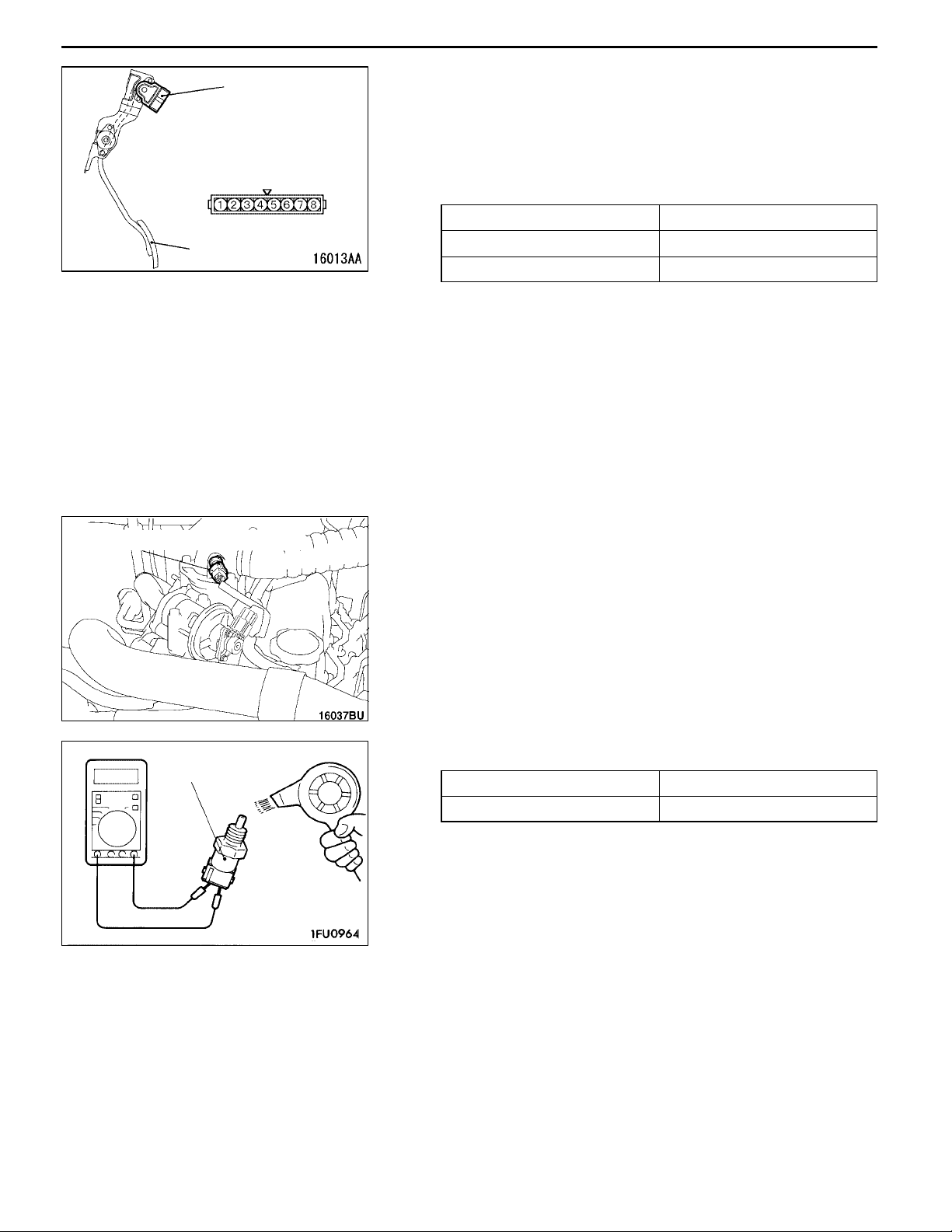
13-60
FUEL SYSTEM <4D5-Step III> - On-vehicle Service
APS
Connector at the
equipment
Accelerator
pedal
Boost air temperature sensor
IDLE SWITCH CHECK
1. Disconnect the accelerator pedal position sensor (APS)
connector.
2. Check the continuity between the idle switch connector
terminal No. 4 (idle switch) and terminal No. 5 (earth).
Normal condition:
Accelerator pedal Continuity
Step on None
Release Yes
3. Replace APS if it is inoperative.
NOTE
Make an adjustment on APS after replacement.(Refer
to P.13-58.)
BOOST AIR TEMPERATURE SENSOR (INTAKE
AIR TEMPERATURE SENSOR) CHECK
Boost air temperature
sensor
1. Remove the boost air temperature sensor.
2. Measure the resistance at the boost air temperature
sensor connector terminal.
Standard value:
2.3 - 3.0 kΩ (at 20_C)
0.30 - 0.42 kΩ (at 80_C)
3. Measure the resistance at the sensor part being warmed
up by a hair dryer.
Normal condition:
Temperature (_C) Resistance value (kΩ)
Rising Become smaller
4. If the resistance is not within the range of the standard
value or does not change at all, replace the boost air
temperature sensor.
NOTE
Replace the gasket as well.
5. Tighten the boost air temperature sensor to the specified
torque.
Tightening torque: 14 ± 1 N·m
Page 84

FUEL SYSTEM <4D5-Step III> - On-vehicle ServiceFUEL SYSTEM <4D5-Step III> - On-vehicle Service
13-61
Engine coolant
temperature sensor
ENGINE COOLANT TEMPERATURE SENSOR
CHECK
1. Remove the engine coolant temperature sensor.
2. Measure the resistance between the terminals of the
connectors while immersing the sensor part of the engine
coolant temperature sensor in the hot water.
Standard value:
2.1 - 2.7 kΩ (at 20_C)
0.26 - 0.36 kΩ (at 80_C)
3. If the resistance is not within the range of the standard
value, replace the engine coolant temperature sensor.
4. Apply the sealant to the thread of the engine coolant
temperature sensor and tighten it to the specified torque.
Sealant:
3M Nut Locking Part No. 4171 or equivalent
Tightening torque: 36 ± 6 N·m
Equipment
side connector
EGR valve
position
sensor
EGR VALVE POSITION SENSOR CHECK
1. Disconnect the EGR valve position sensor connector.
2. Measure the resistance between the EGR valve position
sensor side connector terminal No. 2 and terminal No.
3.
Standard value: 3.5 - 6.5 kΩ
3. Install a hand vacuum pump to the EGR valve nipple.
4. Measure the resistance between the EGR valve position
sensor-side connector terminal No. 1 and terminal No.
3 when a negative pressure is applied.
Normal condition:
Slowly increase the negative
pressure to 60 kPa.
5. If the resistance is outside the standard value, or if it
doesn’t change smoothly, replace the EGR valve position
sensor.
Changes smoothly in
proportion to the negative
pressure
Page 85

13-62
FUEL SYSTEM <4D5-Step III> - On-vehicle Service
Connector at the
equipment (12 pin)
Connector at the
equipment (12 pin)
Fuel cut
solenoid
valve
Fuel cut solenoid
valve
Timing
control
valve
FUEL INJECTION PUMP CHECK
FUEL CUT SOLENOID VALVE CHECK
Operation noise check
1. Attach the sound scope to the fuel cut solenoid valve
to check for running noise when the ignition switch is
“ON” position.
Coil resistance check
1. Disconnect the injection pump connector (12 pin).
2. Measure the resistance between terminal No. 1 (fuel cut
solenoid valve) and the injection pump body.
Standard value: 6.8 - 9.2 Ω
TIMING CONTROL VALVE CHECK
1. Disconnect the injection pump connector (12 pin).
2. Measure the resistance between terminal No. 5 and
terminal No. 9.
Standard value: 10.8 - 11.2 Ω
Connector at the
equipment (12 pin)
Connector at the
equipment (12 pin)
GE ACTUATOR (ELECTRONIC GOVERNOR) CHECK
1. Disconnect the injection pump connector (12 pin).
2. Measure the resistance between terminal No. 6 and
terminal No. 10.
Standard value: 0.64 - 0.72 Ω
FUEL TEMPERATURE SENSOR CHECK
1. Disconnect the injection pump connector (12 pin).
2. Measure the resistance between terminal No. 7 and
terminal No. 11.
Standard value: 1.4 - 2.6 kΩ
Page 86

FUEL SYSTEM <4D5-Step III> - On-vehicle Service
13-63
Connector at the
equipment (12 pin)
Connector at
the equipment
Timer piston position sensor
Pump speed sensor-side
connector
CONTROL SLEEVE POSITION SENSOR CHECK
1. Disconnect the injection pump connector (12 pin).
2. Measure the resistance between the following terminals.
Standard value:
Terminal No. 4 - Terminal No. 12 11.2 - 12.4 Ω
Terminal No. 4 - Terminal No. 8 5.6 - 6.2 Ω
Terminal No. 8 - Terminal No. 12 5.6 - 6.2 Ω
TIMER PISTON POSITION SENSOR CHECK
1. Disconnect the timer piston position sensor connector.
2. Measure the resistance between the following terminals.
Standard value:
Terminal No. 1 - Terminal No. 2 160 - 168 Ω
Terminal No. 1 - Terminal No. 3 80 - 84 Ω
Terminal No. 2 - Terminal No. 3 80 - 84 Ω
PUMP SPEED SENSOR CHECK
1. Disconnect the pump speed sensor connector.
2. Measure the resistance between terminals No. 1 and
No. 2.
Standard value: 1.36 - 1.84 kΩ
Pump speed sensor
Throttle solenoid valve
B
A
THROTTLE SOLENOID VALVE CHECK
INSPECTION PROCEDURE
1. Disconnect the vacuum hose (black and yellow stripe)
from the solenoid valve.
2. Disconnect the harness connector.
3. Install a hand vacuum pump to solenoid valve nipple
B.
4. Use jumper leads to connect the solenoid valve terminals
and the battery terminals.
5. Disconnect the jumper lead from the battery ( -) terminal,
and then apply negative pressure to check the
air-tightness.
Battery
Page 87

13-64
FUEL SYSTEM <4D5-Step III> - On-vehicle Service
Standard value:
Jumper lead Nipple A Normal condition
Connected
Disconnected Open Negative pressure
COIL RESISTANCE CHECK
1. Measure the resistance between the solenoid valve
terminals.
Standard value: 29 - 35 Ω (at 20_C)
Open Negative pressure
Closed Negative pressure
leaks
maintained
maintained
Throttle actuator
THROTTLE ACTUATOR CHECK
1. Remove the vacuum hose (yellow stripe) from the throttle
actuator and connect a hand vacuum pump to the throttle
actuator nipple.
2. Check that the actuator rod moves smoothly when
applying vacuum gradually.
Also, check that the vacuum is maintained when applying
53 kPa of vacuum.
VARIABLE GEOMETRY SOLENOID VALVE
CHECK
Refer to GROUP 15 - On-vehicle Service.
EGR CONTROL SOLENOID VALVE CHECK
Refer to GROUP 17 - Emission Control System <4D5-step
III>.
Page 88

FUEL SYSTEM <4D5-Step III> - Fuel Injection Pump
FUEL INJECTION PUMP
REMOVAL AND INSTALLATION
13-65
Pre-removal Operation
D Engine Coolant Draining.
D Battery and Battery Tray Removal
D Intercooler Removal (Refer to GROUP 15.)
D Timing Belt Removal (Refer to GROUP 11.)
10 ± 2 N·m
5.0 ± 1.0 N·m
30 ± 7 N·m
7
Post-installation Operation
D Timing Belt Installation (Refer to GROUP 11.)
D Intercooler Installation (Refer to GROUP 15.)
D Battery and Battery Tray Installation
D Engine Coolant Supplying.
30 ± 7 N·m
5.0 ± 1.0 N·m
3
12 ± 1 N·m
2
4
5
6
83 ± 5 N·m
Removal steps
1. Fuel injection pump connector
2. Fuel hoses connection
AA" 3. Fuel injection pipe
4. Engine oil level gauge guide and
oil level gauge assembly
1
23 ± 3 N·m
19 ± 3 N·m
AB" 5. Fuel injection pump sprocket
6. Flange
7. Fuel injection pump
(Engine oil)
REMOVAL SERVICE POINTS
AA" FUEL INJECTION PIPE REMOVAL
Loosen the nuts at the end of the injection pipe with the
delivery holder (for pump side) and injection nozzle assembly
(for nozzle side) retained by a spanner, etc.
Delivery holder
Nut
Page 89

13-66
MB990767
FUEL SYSTEM <4D5-Step III>-Fuel Injection Pump/Crankshaft position sensor
AB" FUEL INJECTION PUMP SPROCKET REMOVAL
1. Use the special tool to stop the fuel injection pump sprocket
from turning, and remove the fuel injection pump sprocket
mounting bolt.
MD998719
2. Use the special tool to remove the fuel injection pump
sprocket.
Caution
(1) Do not hit pump drive shaft with hammer, etc.
(2) When holding injection pump, do not allow to
dangle by holding accelerator lever or fast idle
lever.
Do not remove these levers. Removal will cause
injection pump malfunction.
MD998388
CRANKSHAFT POSITION SENSOR
REMOVAL AND INSTALLATION
Pre-removal and Post-installation Operation
D Timing Belt Cover Removal and Installation
(Refer to GROUP 11.)
Crankshaft position
sensor
9.0 ± 1.0 N·m
Page 90

FUEL SYSTEM <4D5-Step III> - Accelerator Pedal
ACCELERATOR PEDAL
REMOVAL AND INSTALLATION
Post-installation Operation
D Accelerator Pedal Position Sensor Check and
Adjustment (Refer to P.13-58.)
13-67
10
12
6
2
8
3.5 ± 1.0 N·m
3
5.0 ± 1.0 N·m
1
10 ± 2 N·m
12
7
9
10
11
10
5
6
5
4
9
8
Removal steps
1. Accelerator pedal position sensor
2. Accelerator pedal assembly
3. Hysteresis assembly
4. Push-on spring nut
5. Bushing
6. Spring
7. Accelerator arm and pedal
assembly
8. Accelerator pedal
9. Spring
10. Accelerator arm
11. Pedal stopper
12. Accelerator pedal bracket
Page 91

NOTES
Page 92

COOLING
CONTENTS
14-1
GENERAL 2.................................
Outline of Change 2............................
SPECIFICATIONS 2..........................
General Specification 2.........................
WATER HOSE AND WATER PIPE <4D5> 3....
Page 93

14-2
COOLING - Outline of Changes/Specifications
GENERAL
OUTLINE OF CHANGES
With the modification below by additional emission regulation step III compatible 4D56 engine, the service
procedure of the part that is different from previous service procedure has been established.
D The turbocharger has been changed to a Variable Geometry (VG) type. Due to this change, an EGR
cooler has been added and section ”Water hose and water pipe” has been changed.
D Heat release of the radiator has been enhanced to correspond to a newly introduced Variable Geometry
(VG) turbocharger.
SPECIFICATIONS
GENERAL SPECIFICATION
Items Specifications
Radiator Performance kJ/h 4D5-Step III 236,500
Page 94

COOLING - Water Hose and Water Pipe <4D5-Step III>
WATER HOSE AND WATER PIPE <4D5-Step III>
REMOVAL AND INSTALLATION
Pre-removal and Post-installation Operation
D Engine Coolant Draining and Supplying.
16
14-3
3
11 ± 1 N·m
22 ± 4 N·m
4
5
6
14 ± 1 N·m
13
15
14
8
14 ± 1 N·m
10
7
11
1
9
12
42 ± 7 N·m
18
17
14 ± 1 N·m
2
11 ± 1 N·m
Removal steps
D Injection pipe
1. Heater hose connection
2. Water hose
D Air cleaner assembly
3. Water pipe and hose assembly
"AA 4. Water hose
5. Water pipe E
"BA 6. O-ring
"AA 7. Water hose
8. Hose protector
D EGR valve, EGR cooler
(Refer to GROUP 17.)
D Turbocharger heat protector (Refer to
GROUP 15 - Intake and exhaust
manifold, turbocharger.)
9. Water hose
10. Hose protector
11. Water pipe A
12. Gasket
13. Water pipe B
14. Gasket
15. Water hose
16. Hose protector
17. Water pipe C
18. Water pipe D
Page 95

14-4
COOLING - Water Hose and Water Pipe <4D5-Step III>
INSTALLATION SERVICE POINTS
EGR cooler side
"AA WATER HOSE INSTALLATION
The identification mark on the water hose end should face
toward the EGR cooler.
Identification
mark
Water pipe
Hose protector
O-ring
Water hose
INSTALLATION SERVICE POINTS
"BA O-RING INSTALLATION
Rinse the mounting location of the O-ring and water pipe
with water, and install the O-ring and water pipe.
Caution
1. Care must be taken not to permit engine oil or other
greases to adhere to the O-ring.
2. When inserting the pipe, check to be sure that there
is no sand, dirt, etc. on its inner surface.
Page 96

INTAKE AND
EXHAUST
CONTENTS
15-1
GENERAL 2.................................
Outline of Changes 2...........................
GENERAL INFORMATION <4D5-Step III>2...
SERVICE SPECIFICATIONS <4D5-Step III>3..
SEALANT <4D5-Step III>3..................
ON-VEHICLE SERVICE 4.....................
Turbocharger Supercharging Check 4............
Supercharging Pressure Control
System Check 4...............................
Variable Geometry Actuator Check 5.............
Variable Geometry Solenoid Valve Check 5.......
INTERCOOLER <4D5-Step III>6.............
INTAKE MANIFOLD AND EXHAUST
MANIFOLD, THROTTLE BODY AND
TURBOCHARGER <4D5-Step III>7...........
EXHAUST PIPE AND MAIN MUFFLER
<4D5-Step III>9.............................
Page 97

15-2
INTAKE AND EXHAUST -
General/General Information
GENERAL
OUTLINE OF CHANGES
With the modification below by additional emission regulation step III compatible 4D5 engine, the service
procedure of the part that is different from previous service procedure has been established.
D The turbocharger has been changed to a Variable Geometry (VG) type.
D A catalytic converter has been added.
D The variable geometry turbocharger can not be disassembled, and must be always replaced as an
assembly.
GENERAL INFORMATION <4D5-Step III>
The variable geometry solenoid valve is duty controlled to control the variable nozzle opening angle of the
variable geometry turbocharger. This allows to obtain the characteristic of boost pressure corresponding to
the engine operation status.
<At starting - driving at low speed>
Nozzle vane fully closed
Exhaust gas
<Driving at high speed>
Nozzle vane fully opened
Turbin wheel
Nozzle turned to
the direction of the
circumference of
a circle
Stopper bolt
Turbin wheel
Nozzle turned
to the direction
of the shaft
To vacuum
pump
Variable geometry
control pressure sensor
Vacuum pressure
increased (rod
activated)
To vacuum
pump
Variablegeometry control
pressure sensor
Variable geometry
solenoid valve
Variable geometry actuator
Variable geometry
solenoid valve
Exhaust gas
Stopper bolt
Vacuum pressure
decreased (rod
deactivated)
Variable geometry actuator
Page 98
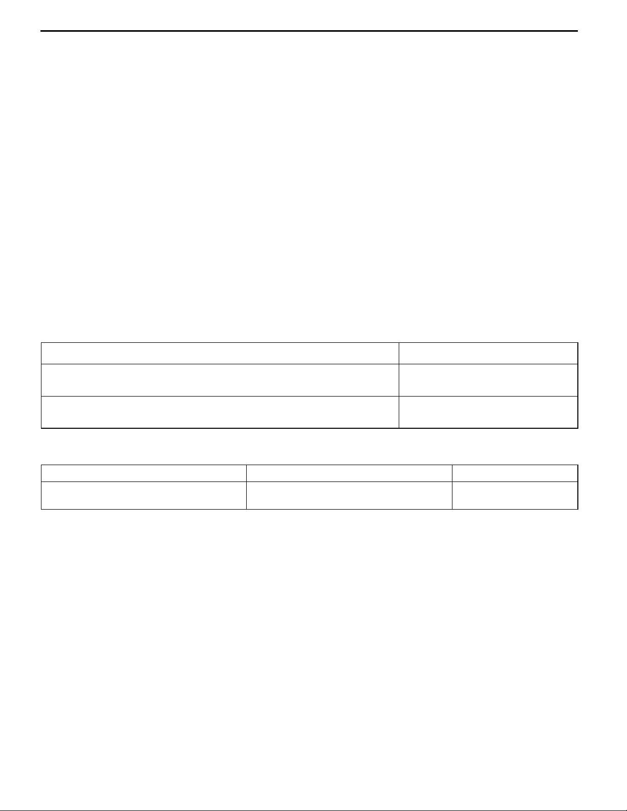
INTAKE AND EXHAUST - General Information/Service Specifications/Sealant
15-3
At starting and driving at low speed, the duty control
value of the variable geometry solenoid valve is
increased to apply the vacuum pressure of the
vacuum pump to the variable geometry actuator.
Applying the vacuum pressure to the variable
geometry actuator pulls the actuator rod so that
it can move towards the direction of closing the
variable nozzle of the variable geometry
turbocharger. As closing the nozzle reduces the
exhaust gas mass, the speed of exhaust gas flow
will be increased and efficiency will be improved.
Since the characteristic of boost pressure becomes
a low speed type, boost pressure will suddenly
rise from low speed.
At driving at high speed, the duty control value
of the variable geometry solenoid valve is
decreased to reduce the vacuum pressure from
the vacuum pump so that the actuator rod can
return to the deactivated status and move towards
the direction of opening the nozzle of the variable
geometry turbocharger.
Opening the nozzle allows the characteristic of
boost pressure to become a high speed type so
that the appropriate boost pressure can be
maintained.
Therefore, boost pressure can be controlled by
appropriate duty control of the variable geometry
solenoid valve. The engine-ECU calculates the
correct boost pressure based on the engine speed
and fuel injection amount. Furthermore, the duty
control of the variable geometry solenoid valve is
given feedback of the signals from the variable
geometry control pressure sensor and the boost
pressure sensor so that the variable nozzle opening
angle of the variable geometry turbocharger can
be quickly adjusted to obtain the desired boost
pressure.
SERVICE SPECIFICATIONS <4D5-Step III>
Items Standard value
Variable geometry actuator activation vacuum
(Approximately 1 mm stroke) kPa
Variable geometry solenoid valve coil resistance
(at 20°C) Ω
Approximately 10.5 - 12.5
29 - 35
SEALANT <4D5-Step III>
Item Specified sealant Remarks
Thread of the intake manifold mounting
bolts
3M Stud Locking No.4170 or equivalent Anaerobic sealant
Page 99

15-4
INTAKE AND EXHAUST - On-vehicle Service
ON-VEHICLE SERVICE
TURBOCHARGER SUPERCHARGING CHECK
Caution
Conduct the driving test in a location where driving at
full acceleration can be done with safety. Two person
should be in the vehicle when the test is conducted; the
person in the passenger seat should read the indications
shown by the MUT-II.
1. Set the vehicle to the pre-inspection condition.
2. Turn the ignition switch to “LOCK” (OFF) position, and
connect the diagnosis connector to the MUT-II.
3. Use the data list function named “Item No. 04” boost
pressure sensor of the MUT-II to check the supercharging
pressure when the engine speed increases to
approximately 3,000 r/min or more by driving at full
acceleration in 2nd.
4. When the indicated supercharger does not become
positive pressure, check the following items.
D Malfunction of the boost pressure sensor
D Leakage of supercharging pressure
D Malfunction of the turbocharger
5. When the indicated supercharger is 133 kPa or more,
supercharging control may be faulty, therefore check the
followings.
D Malfunction of the variable geometry actuator
D Malfunction of the variable nozzle
D Malfunction of the variable geometry solenoid valve
D Malfunction of the boost pressure sensor
D Malfunction of the variable geometry control pressure
sensor
SUPERCHARGING PRESSURE CONTROL
SYSTEM CHECK
1. Set the vehicle to the pre-inspection condition.
2. Turn the ignition switch to “LOCK” (OFF) position, and
connect the diagnosis connector to the MUT-II.
3. Start the engine, and let it run at idle.
4. Select the actuator testing function named “Item No. 35
or No. 36” of the MUT-II to check that the variable geometry
actuator vacuum and the supercharging pressure increase
when the variable geometry solenoid valve is activated.
Variable geometry
solenoid valve condition
OFF 0 kPa Approximately -1
ON Approximately 80
Variable geometry
actuator vacuum
kPa
Supercharging
pressure
kPa
Approximately 3
kPa
Page 100

INTAKE AND EXHAUST - On-vehicle Service
NOTE
(1) If the variable geometry actuator vacuum is not in a normal
condition, the variable geometry actuator, variable
geometry solenoid valve, variable geometry control
pressure sensor, vacuum pump or hose may be faulty.
(2) If the variable geometry actuator vacuum is in a normal
condition but the supercharging pressure is not in a normal
condition, the variable geometry turbocharger nozzle,
boost pressure sensor, or hose may be faulty.
Caution
Be careful not to forcibly activate the variable geometry
solenoid valve to the fullest degree when running at a
high speed. Too much supercharging pressure could
damage the engine or the turbocharger.
15-5
Variable geometry
actuator
A
B
C
VARIABLE GEOMETRY ACTUATOR CHECK
1. Connect the hand vacuum pump to nipple.
2. While gradually applying vacuum, check the vacuum that
begins to active (approximately 1 mm stroke) the variable
geometry actuator rod.
Standard value: Approximately 10.5 - 12.5 kPa
Caution
In order to avoid damage to the diaphragm, do not apply a
vacuum of 59 kPa or higher.
3. If there is a significant deviation from the standard value,
check the actuator or the variable nozzle: replace if
necessary.
VARIABLE GEOMETRY SOLENOID VALVE
CHECK
NOTE
When disconnecting the vacuum hose, always make a mark
so that it can be reconnected at original position.
1. Disconnect the vacuum hose (black, red stripe) from the
solenoid valve.
2. Disconnect the harness connector.
3. Connect a hand vacuum pump to the nipple to which
the red striped vacuum hose was connected.
4. Check airtightness by applying a vacuum with voltage
applied directly from the battery to the variable geometry
solenoid valve and without applying voltage.
Battery
 Loading...