

Page 1
Page 2

MELDAS is a registered trademark of Mitsubishi Elec tric Corporation.
Other company and product names that appear in this manual are tradema rks or registered
trademarks of their respective companies.
Page 3

Page 4

Introduction
Thank you for selecting the Mitsubishi numerical control unit. This instruction manual describes the
handling and caution points for using this AC servo/spindle.Incorrect handling may lead to unforeseen
accidents, so always read this instruction manual thoroughly to ensure correct usage.
In order to confirm if all function specifications described in this manual are applicable, refer to the
specifications for each CNC.
Notes on Reading This Manual
(1) Since the description of this specification manual deals with NC in general, for the specifications of
individual machine tools, refer to the manuals issued by the respective machine manufacturers.
The "restrictions" and "available functions" described in the manuals issued by the machine
manufacturers have precedence to those in this manual.
(2) This manual describes as many special operations as possible, but it should be kept in mind that
items not mentioned in this manual cannot be performed.
Page 5

Page 6

Precautions for safety
DANGER
WARNING
CAUTION
Please read this manual and auxiliary documents before starting installation, operation, maintenance or
inspection to ensure correct usage. Thoroughly understand the device, safety information and
precautions before starting operation.
The safety precautions in this instruction manual are ranked as "WARNING" and "CAUTION".
When there is a potential risk of fatal or serious injuries if handling is mistaken.
When a dangerous situation, or fatal or serious injuries may occur if handling is mistaken.
When a dangerous situation may occur if handling is mistaken leading to medium or minor
injuries, or physical damage.
Note that some items described as " CAUTION" may lead to major results depending on the situation.
In any case, important information that must be observed is described.
Page 7
The signs indicating prohibited and mandatory matters are explained below.
Indicates a prohibited matter. For example, "Fire Prohibited" is indicated as .
Indicates a mandatory matter. For example, grounding is indicated as .
The meaning of each pictorial sign is as follows.
CAUTION
Prohibited
CAUTION rotated
Disassembly is
prohibited
object
CAUTION HOT Danger Electric shock
KEEP FIRE AWAY General instruction
Danger explosive
risk
Earth ground
After reading this specifications and instructions manual, store it where the user can access it easily for
reference.
The numeric control unit is configured of the control unit, operation boar d, servo drive unit, spi ndle drive
unit, power supply, servomotor and spindle mo to r, et c.
In this section "Precautions for safety", the following items are generically called the "motor".
• Servomotor
• Linear servomotor
• Spindle motor
In this section "Precautions for safety", the following items are generically called the "unit".
• Servo drive unit
• Spindle drive unit
• Power supply unit
• Scale interface unit
• Magnetic pole detection unit
POINT
Important matters that should be understood for operation of this machine are indicated as a POINT
in this manual.
Page 8

1. Electric shock prevention
Do not open the front cover while the power is ON or during operation . Failure to observe this could lead
to electric shocks.
Do not operate the unit with the front cover removed. The high voltage terminals and charged sections
will be exposed, and can cause electric shocks.
Do not remove the front cover and connector even when the power is OFF unless carrying out wiring
work or periodic inspections. The inside of the units is charged, and can cause electric shocks.
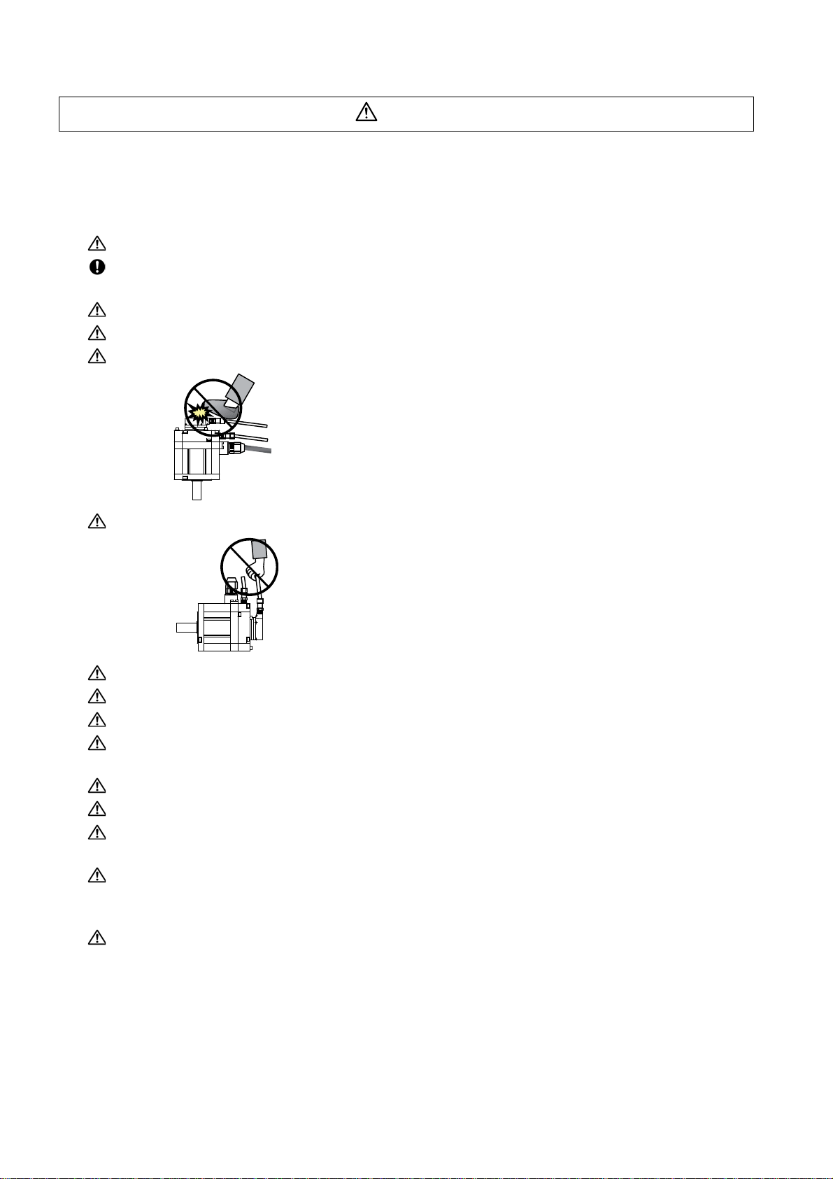
Since the high voltage is supplied to the main circuit connector while the power is ON or during
operation, do not touch the main circuit connector with an adjustment screwdriver or the pen tip. Fa ilure
to observe this could lead to electric shocks.
Wait at least 15 minutes after turning the power OFF, confirm that the CHARGE lamp has gone out, and
check the voltage between P and N terminals with a tester, etc., before starting wiring, maintenance or
inspections. Failure to observe this could lead to electric shocks.
Ground the unit and motor following the standards set forth by each country.
Wiring, maintenance and inspection work must be done by a qualified technician.
Wire the servo drive unit and servomotor after installation. Failure to observe this could lead to electric
shocks.
Do not touch the switches with wet hands. Failure to observe this could lead to electric shocks.
Do not damage, apply forcible stress, place heavy items on the cables or get them caught. Failure to
observe this could lead to electric shocks.
After assembling the built-in IPM spindle motor, if the rotor is rotated by hand etc., voltage occurs
between the terminals of lead. Take care not to get electric shocks.
WARNING
Page 9

2. Injury prevention
In the system where the optical communication with CNC is executed, do not see directly the light
generated from CN1A/CN1B connector of drive unit or the end of cable. When the light gets into eye,
you may feel something is wrong for eye.
(The light source of optical communication corresponds to class1 defined in JISC6802 or IEC60825-1.)
The linear servomotor, direct-drive motor and built-in IPM spindl e motor uses permanent ma gnets in the
rotor, so observe the following precautions .
(1)Handling
• The linear servomotor, direct-drive motor and built-in IPM spindle motor could adversely affect
medical electronics such as pacemakers, etc., therefore, do not approach the rotor.
• Do not place magnetic materials as iron.
• When a magnetic material as iron is placed, take safety measure not to pinch finger s or hands
due to the magnetic attraction force.
• Remove metal items such as watch, piercing jewelry, necklace, etc.
• Do not place portable items that could malfunction or fail due to the influence of the magnetic
force.
• When the rotor is not securely fixed to the machine or device, do not leave it unattended but store
it in the package properly.
(2)Transportation and storage
• Correctly store the rotor in the package to transport and store.
• During transportation and storage, draw people's attention by applying a notice saying "Strong
magnet-Handle with care" to the package or storage shelf.
• Do not use a damaged package.
(3)Installation
• Take special care not to pinch fingers, etc., when installing (and unpacking) the linear servomotor.
Page 10

1. Fire prevention
CAUTION
Install the units, motors and regenerative resistor on non-combustible material. Direct installation on
combustible material or near combustible materials could lead to fires.
Always install a circuit protector and contactor on the servo drive unit power input as explained in this
manual. Refer to this manual and select the correct circuit protector and contactor. An incorrect
selection could result in fire.
Shut off the power on the unit side if a fault occurs in the units. Fires could be caused if a large current
continues to flow.
When using a regenerative resistor, provide a sequence that shuts off the power with the regenerative
resistor's error signal. The regenerative resistor could abnormally overheat and cause a fire due to a
fault in the regenerative transistor, etc.
The battery unit could heat up, ignite or rupture if submerged in water, or if the poles are incorrectly
wired.
Cut off the main circuit power with the contactor when an alarm or emergency stop occurs.
2. Injury prevention
Do not apply a voltage other than that specified in this manual, on each terminal. Failure to observe this
item could lead to ruptures or damage, etc.
Do not mistake the terminal connections. Failure to observe this item could lead to ruptures or damage,
etc.
Do not mistake the polarity (+,- ). Failure to observe this item could lead to ruptures or damage, etc.
Do not touch the radiation fin on unit back face, regenerative resistor or motor, etc., or place parts
(cables, etc.) while the power is turned ON or immediately after turning the power OFF. These parts
may reach high temperatures, and can caus e bu rn s or part dam a ge .
Structure the cooling fan on the unit back face, etc., etc so that it cannot be touched afte r installation.
Touching the cooling fan during operation could lead to injuries.
Page 11
3. Various precautions
CAUTION
Observe the following precautions. Incorrect handling of the unit could lead to faults, injuries and electric
shocks, etc.
(1) Transportation and installation
Correctly transport the product according to its weight.
Use the motor's hanging bolts only when transporting the motor. Do not transport the machine when the
motor is installed on the machine.
Do not stack the products above the tolerable number.
Follow this manual and install the unit or motor in a place where the weight can be borne.
Do not get on top of or place heavy objects on the unit.
Do not hold the cables, axis or detector when transporting the motor.
Do not hold the connected wires or cables when transporting the units.
Do not hold the front cover when transporting the unit. The unit could drop.
Always observe the installation directions of the units or motors.
Secure the specified distance between the units and control panel, or between the servo drive unit and
other devices.
Do not install or run a unit or motor that is damaged or missing parts.
Do not block the intake or exhaust ports of the motor provided with a cooling fan.
Do not let foreign objects enter the units or motors. In particular, if conductive objects such as screws or
metal chips, etc., or combustible materials such as oil enter, rupture or breakage could occur.
Provide adequate protection using a material such as connector for conduit to prevent screws, metallic
detritus, water and other conductive matter or oil and other combustible matter from entering the motor
through the power line lead-out port.
The units, motors and detectors are precision devices, so do not drop them or apply strong impacts to
them.
Page 12
CAUTION
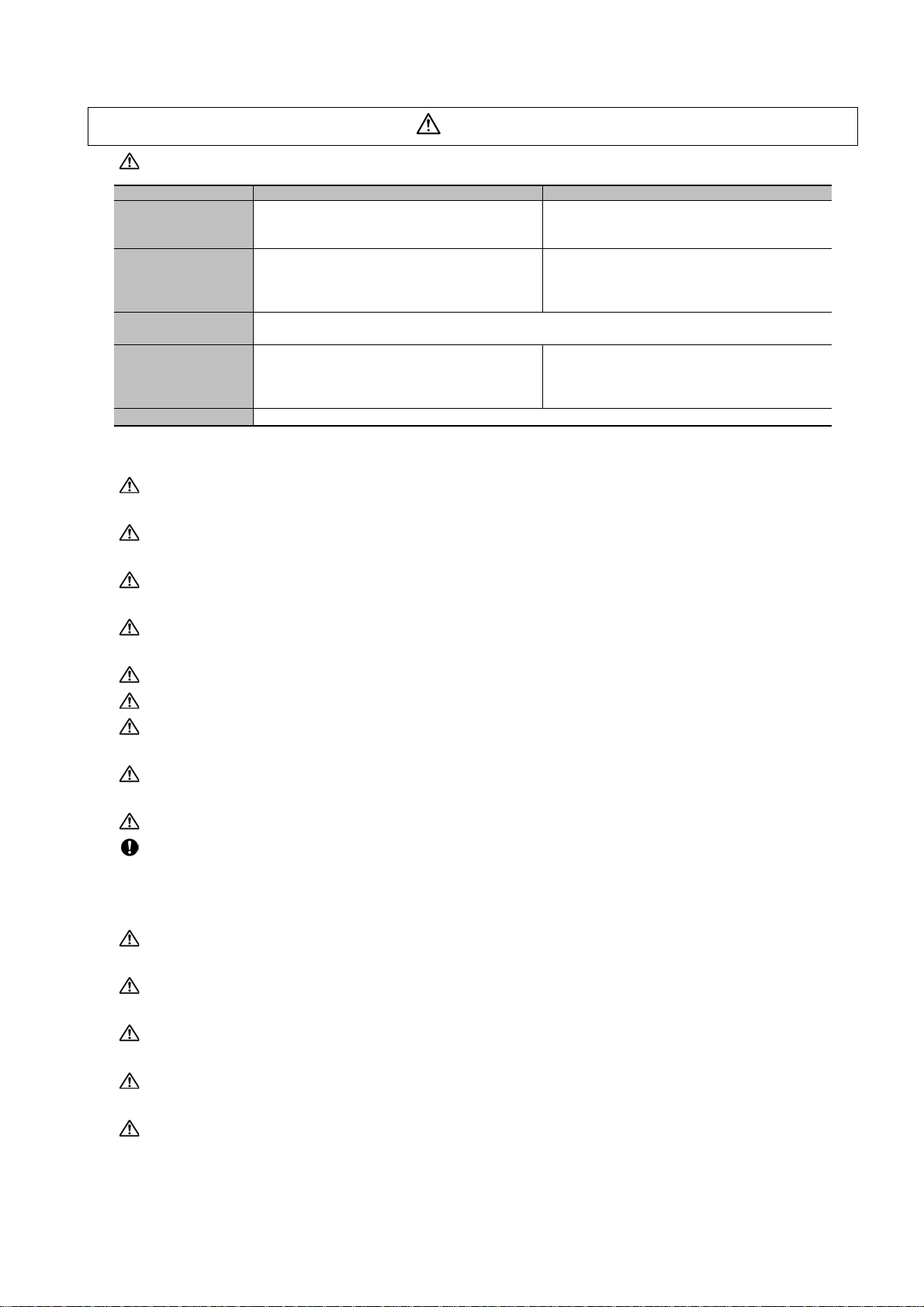
Store and use the units under the following environment conditions.
Environment Unit Motor
Operation: 0 to 55°C(with no freezing),
Ambient temperature
Ambient humidity
Atmosphere
Altitude
Vibration/impact According to each unit or motor specification
Storage / Transportation: -15°C to 70°C
(with no freezing)
Operation: 90%RH or less
(with no dew condensation)
Storage / Transportation: 90%RH or less
(with no dew condensation)
Indoors (no direct sunlight)
With no corrosive gas, inflammable gas, oil mist, dust or conductive fine particles
Operation/Storage: 1000 meters or less above sea
level,
Transportation: 13000 meters or less above sea
level
(Note 1) For details, confirm each unit or motor specifications in addition.
(Note 2) -15°C to 55°C for linear servomotor.
Securely fix the servomotor to the machine. Insufficient fixing could lead to the servomotor slipping off
during operation.
Always install the servomotor with reduction gear in the designated direction. Failure to do so could lead
to oil leaks.
Structure the rotary sections of the motor so that it can never be touched during operation. Install a
cover, etc., on the shaft.
When installing a coupling to a servomotor shaft end, do not apply an impact by hammering, etc. The
detector could be damaged.
Do not apply a load exceeding the tolerable load onto the servomotor shaft. The shaft could break.
Store the motor in the package box.
When inserting the shaft into the built-in IPM spindle mo tor, do not heat the rotor highe r than 130°C. The
magnet could be demagnetized, and the specifications characteristics will not be ensured.
Always use a nonmagnetic tool (explosion-proof beryllium copper alloy safety tool: NGK Insulators, etc.)
when installing the linear servomotor.
Always provide a mechanical stopper on the end of the linear servomotor's travel path.
If the unit has been stored for a long time, always check the operation before starting actual operation.
Please contact the Service Center, Service Station, Sales Office or delayer.
Operation: 0 to 40°C(with no freezing),
Storage: -15°C to 70°C (Note2) (with no freezing)
Operation: 80%RH or less
(with no dew condensation),
Storage: 90%RH or less
(with no dew condensation)
Operation: 1000 meters or less above sea level,
Storage: 10000 meters or less above sea level
(2) Wiring
Correctly and securely perform the wiring. Failure to do so could lead to abnormal operation of the
motor.
Do not install a condensing capacitor, surge absorber or radio noise filter on the output sid e of the drive
unit.
Correctly connect the output side of the drive unit (terminals U, V, W). Failure to do so could lead to
abnormal operation of the motor.
When using a power regenerative power supply unit, always install an AC reactor for each power supply
unit.
In the main circuit power supply side of the unit, always install an appropriate circuit protector or
contactor for each unit. Circuit protector or contactor cannot be shared by several units.
Page 13
CAUTION
RA
)
COM
(24VDC)
RA
Servodrive unit
Servodrive unit
Control output
signal
Control output
signal
Always connect the motor to the drive unit's output terminals (U, V, W).
Do not directly connect a commercial power supply to the servomotor. Failure to observe this could
result in a fault.
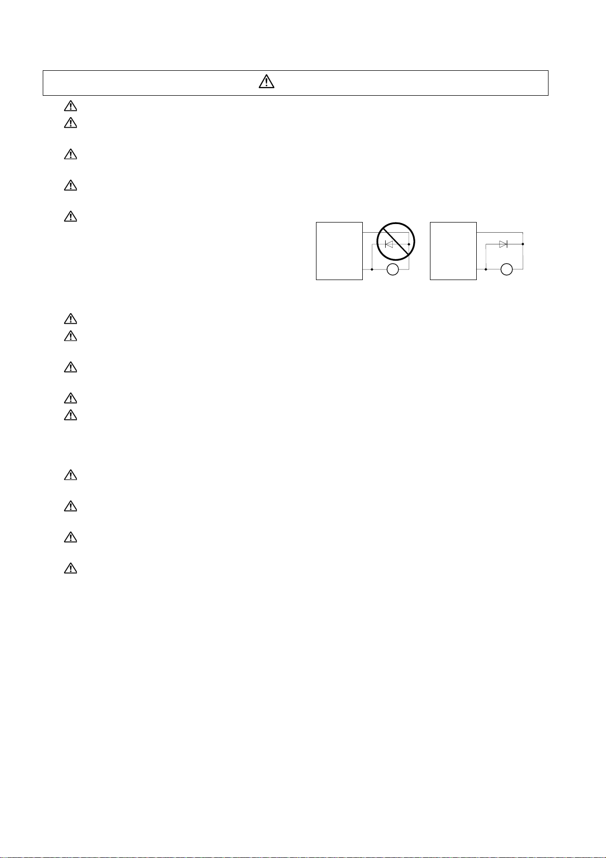
When using an inductive load such as a relay, always connect a diode as a noise measure parallel to
the load.
When using a capacitance load such as a lamp, always connect a protective resistor as a noise
measure serial to the load.
Do not reverse the direction of a diode which
connect to a DC relay for the control output
signals such as contractor and motor brake
output, etc. to suppress a surge. Connecting it
backwards could cause the drive unit to
malfunction so that signals are not output, and
emergency stop and other safety circuits are inoperable.
Do not connect/disconnect the cables connected between the units while the power is ON.
Securely tighten the cable connector fixing screw or fixing mechanism. An insecure fixing could cause
the cable to fall off while the power is ON.
When using a shielded cable instructed in the instruction manual, always ground the cable with a cable
clamp, etc.
Always separate the signals wires from the drive wire and power line.
Use wires and cables that have a wire diameter, heat resistance and flexibility that conforms to the
system.
COM
(24VDC
(3) Trial operation and adjustment
Check and adjust each program and parameter before starting op er ation . Failur e to do so cou l d lead to
unforeseen operation of the machine.
Do not make remarkable adjustments and changes of parameter as the operation could become
unstable.
The usable motor and unit combination is predetermined. Always check the models before starting trial
operation.
The linear servomotor does not have a stopping device such as magnetic brakes. Install a stopping
device on the machine side.
Page 14

(4) Usage methods
CAUTION
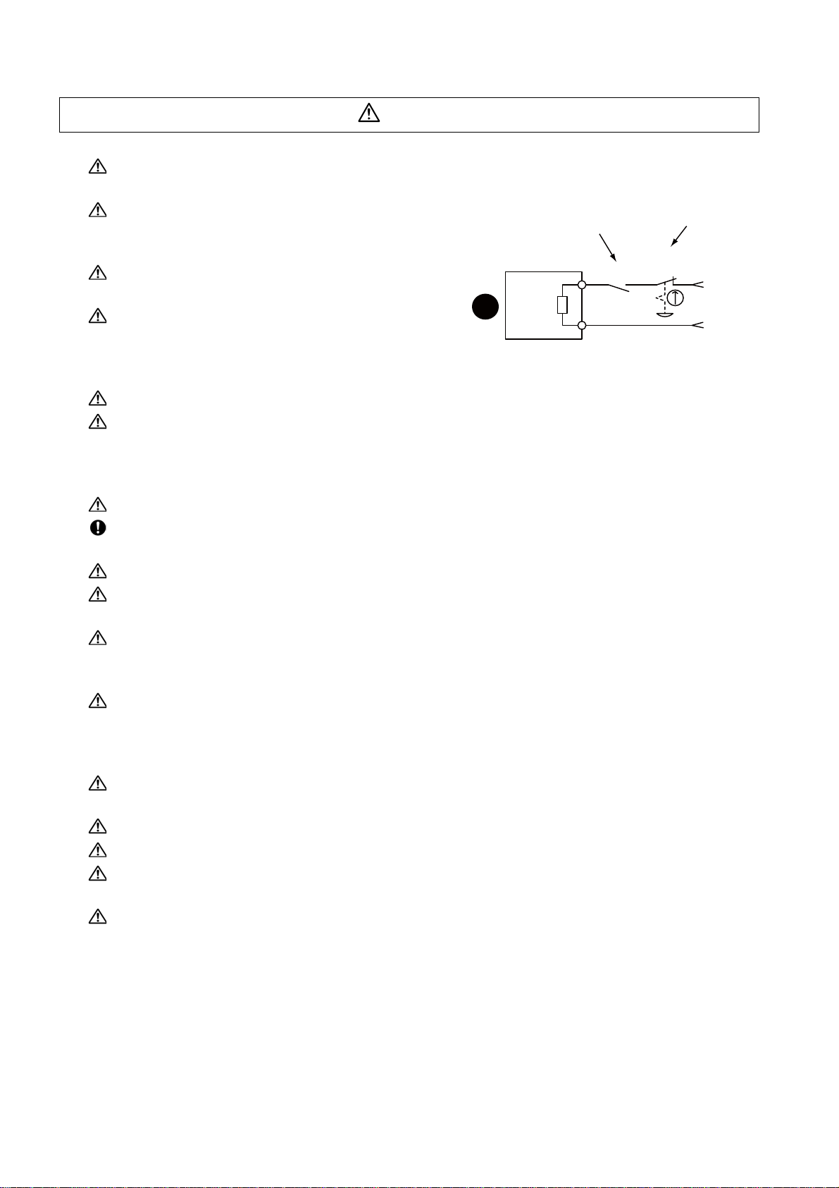
In abnormal state, install an external emergency stop circuit so that the operation can be stopped and
power shut off immediately.
Turn the power OFF immediately if smoke, ab nor ma l noise or odors are generated from the unit or
motor.
Do not disassemble or repair this product.
Never make modifications.
When an alarm occurs, the machine will start suddenly if an alarm reset (RST) is carried out while an
operation start signal (ST) is being input. Always confirm that the operation signal is OFF before
carrying out an alarm reset. Failure to do so could lead to accidents or injuries.
Reduce magnetic damage by installing a noise filter. The electronic devices used near the unit could be
affected by magnetic noise. Install a line noise filter, etc., if there is a risk of magnetic noise.
Use the unit, motor and regenerative resistor with the designated combinatio n. Failur e to do so could
lead to fires or trouble.
The brake (magnetic brake) of the servomotor are for ho ldin g, and m ust not b e used fo r nor mal br aking .
There may be cases when holding is not possible due to the magnetic brake's life, the machine
construction (when ball screw and servomotor are coupled via a timing belt, etc.) or the magnetic
brake's failure. Install a stop device to ensure safety on the machine side.
After changing the programs/parameters or after maintenance an d inspection, always test the operation
before starting actual operation.
Do not enter the movable range of the machine during automatic operation. Never place body parts
near or touch the spindle during rotation.
Follow the power supply specification conditions given in each specification for the power (input voltage,
input frequency, tolerable sudden power failure time, etc.).
Set all bits to "0" if they are indicated as not used or empty in the explanation on the bits.
Do not use the dynamic brakes except during the emergency stop. Continued use of the dynamic
brakes could result in brake damage.
If a circuit protector for the main circuit power supply is shared by several units, the circuit protector may
not activate when a short-circuit fault occurs in a small capacity unit. This is dangerous, so never share
the circuit protector.
Page 15
CAUTION
MBR
EMG
Servomotor
Magnetic
brake
Shut off with the servomotor
brake control output.
Shut off with NC brake
control PLC output.
24VDC
(5) Troubleshooting
If a hazardous situation is predicted during power failure or product trouble, use a servomotor with
magnetic brakes or install an external brake mechanism.
Use a double circuit configuration that allows the
operation circuit for the magnetic brakes to be operated
even by the external emergency stop signal.
Always turn the main circuit power of the motor OFF
when an alarm occurs.
If an alarm occurs, remove the cause, and secure the
safety before resetting the alarm.
(6) Maintenance, inspection and part replacement
Always backup the programs and parameters be fo re star tin g ma in te na nc e or insp ect ion s.
The capacity of the electrolytic capacitor will drop over time due to self-discharging, etc. To prevent
secondary disasters due to failures, replacing this part every five years when used under a normal
environment is recommended. Contact the Service Center, Service Station, Sales Office or delayer for
repairs or part replacement.
Do not perform a megger test (insulation resistance measurement) during inspections.
If the battery low warning is issued, back up the machining programs, tool data and parameters with an
input/output unit, and then rep l ac e th e ba ttery.
Do not short circuit, charge, overheat, incinerate or disassemble the battery.
For after-purchase servicing of the built-in motor (including the detector), supplies of servicing parts and
repairs can only be offered.
For maintenance, part replacement, and services in case of failures in the built-in motor (including the
detector), take necessary actions at your end. For spindle drive unit, Mitsubishi can offer the afterpurchase servicing as with the general spindle drive unit.
When a failure has occurred in the built-in motor (including the detector), some period of time can be
required to supply the servicing parts or repair. Prepare the spare parts a t your end whenever possible.
(7) Disposal
Take the batteries and backlights for LCD, etc., off from the controller, drive unit an d motor, and dispose
of them as general industrial wastes.
Do not disassemble the unit or motor.
Dispose of the battery according to local laws.
Always return the secondary side (magnet side) of the linear servomotor to the Service Center or
Service Station.
When incinerating optical communication cable, hydrogen fluoride gas or hydrogen chloride gas which
is corrosive and harmful may be generated. For disposal of optical communication cable, request for
specialized industrial waste disposal services that has incineration facility for disposing hydrogen
fluoride gas or hydrogen chloride gas.
Page 16

CAUTION
(8) Transportation
The unit and motor are precision parts and must be handled carefully.
According to a United Nations Advisory, the battery unit and battery must be transported according to
the rules set forth by the International Civil Aviation Organization (ICAO), International Air
Transportation Association (IATA), International Maritime Organization (IMO), and United States
Department of Transportation (DOT), etc.
(9) General precautions
The drawings given in this manual show the covers and safety partitions, etc., removed to provide a
clearer explanation. Always return the covers or partitions to their respective places before starting
operation, and always follow the instructions given in this manual.
Page 17

Page 18

Treatment of waste
The following two laws will apply when disposing of this product. Considerations must be made to each law.
The following laws are in effect in Japan. Thus, when using this product overseas, the local laws will have a
priority. If necessary, indicate or notify these laws to the final user of the product.
(1) Requirements for "Law for Promotion of Effective Utilization of Resources"
(a) Recycle as much of this product as possible when finished with use.
(b) When recycling, often parts are sorted into steel scraps and electric parts, etc., and sold to scrap
contractors. Mitsubishi recommends sorting the product and selling the members to appropriate
contractors.
(2) Requirements for "Law for Treatment of Waste and Cleaning"
(a) Mitsubishi recommends recycling and selling the product when no longer nee ded according to item
(1) above. The user should make an effort to reduce waste in this manner.
(b) When disposing a product that cannot be resold, it shall be treated as a waste product.
(c) The treatment of industrial waste must be commissioned to a licensed industrial waste treatment
contractor, and appropriate measures, including a manifest control, must be taken.
(d) Batteries correspond to "primary batteries", and must be disposed of according to local disposal
laws.
Page 19

Page 20

Disposal
(Note) This symbol mark is for EU countries only.
This symbol mark is according to the directive 2006/66/EC Article 20 Information for endusers and Annex II.
Your MITSUBISHI ELECTRIC product is designed and manufactured with high quality materials and
components which can be recycled and/or reused.
This symbol means that batteries and accumulators, at their end-of-life, should be disposed of
separately from your household waste.
If a chemical symbol is printed beneath the symbol shown above, this chemical symbol means that the
battery or accumulator contains a heavy metal at a certain concentration. This will be indicated as
follows:
Hg: mercury (0,0005%), Cd: cadmium (0,002%), Pb: lead (0,004%)
In the European Union there are separate collection systems for used batteries and accumulators.
Please, dispose of batteries and accumulators correctly at your local community waste collection/
recycling centre.
Please, help us to conserve the environment we live in!
Page 21

Page 22

Contents
1 Introduction................................................................1 - 1
1-1 Servo/spindle drive system configuration ......................................................................................... 1 - 2
1-1-1 System configuration............. ... ... .... ... .......................................... ... ......................................... 1 - 2
1-2 Explanation of type ...........................................................................................................................1 - 3
1-2-1 Servomotor type....................................... .......................................... ... ...................................1 - 3
1-2-2 Servo drive unit type.... ... .......................................... .... ... .......................................... ............... 1 - 4
1-2-3 Spindle motor type.................................................................................................................... 1 - 5
1-2-4 Tool spindle motor type......................................... .......................................... ... ......................1 - 6
1-2-5 Spindle drive unit type.............................................................................................................. 1 - 7
2 Specifications.............................................................2 - 1
2-1 Servomotor....................................................................................................................................... 2 - 2
2-1-1 Specifications list................... ... ... .......................................... .... ... ............................................ 2 - 2
2-1-2 Torque characteristics................................. .... ... ... .......................................... ... ......................2 - 5
2-2 Spindle motor.................................................................................................................................... 2 - 7
2-2-1 Specifications ........ ... ... ... .... ... ... .......................................... ... ................................................... 2 - 7
2-2-2 Output characteristics.................................. .... ... ... ... .......................................... .... ................2 - 13
2-3 Tool spindle motor..........................................................................................................................2 - 16
2-3-1 Specifications ........ ... ... ... .... ... ... .......................................... ... ................................................. 2 - 16
2-3-2 Output characteristics.................................. .... ... ... ... .......................................... .... ................2 - 18
2-4 Drive unit.........................................................................................................................................2 - 20
2-4-1 Installation environment conditions ........................................................................................2 - 20
2-4-2 Servo drive unit...................................... .......................................... ... .................................... 2 - 20
2-4-3 Spindle drive unit....................................................................................................................2 - 21
2-4-4 Unit outline dimension drawing........................................ ... ... .... ... ... ... ... .... ... ... ....... ... ... ... .......2 - 22
2-4-5 Explanation of each part.........................................................................................................2 - 23
3 Function Specifications.............................................3 - 1
Function specifications list......................................................................................................................3 - 2
3-1 Base functions..................................................................................................................................3 - 4
3-1-1 Full closed loop control....... ... ... ... .... ... ... ... .......................................... ... ................................... 3 - 4
3-1-2 Position command synchronous control...................................................................................3 - 4
3-1-3 Speed command synchronous control.....................................................................................3 - 5
3-1-4 Distance-coded reference position control...............................................................................3 - 5
3-1-5 Spindle's continuous position loop control................................................................................3 - 6
3-1-6 Coil changeover control............................................................................................................ 3 - 7
3-1-7 Gear changeover control................. ... ... ... ... .......................................... .... ............................... 3 - 7
3-1-8 Orientation control................................. .......................................... ... ...................................... 3 - 7
3-1-9 Indexing control............................... ... ... ... ... .... ... .......................................... ... .........................3 - 7
3-1-10 Synchronous tapping control.................................................................................................. 3 - 7
3-1-11 Spindle synchronous control ..................................................................................................3 - 7
3-1-12 Spindle/C axis control............................................................................................................. 3 - 7
3-1-13 Proximity switch orientation control........................................................................................ 3 - 7
3-2 Servo/Spindle control functions ........................................................................................................ 3 - 8
3-2-1 Torque limit function................................................................................................................. 3 - 8
3-2-2 Variable speed loop gain control..............................................................................................3 - 8
3-2-3 Gain changeover for synchronous tapping control...................................................................3 - 8
3-2-4 Speed loop PID changeover control.........................................................................................3 - 9
3-2-5 Disturbance torque observer.................................................................................................... 3 - 9
3-2-6 Smooth High Gain control (SHG control) ............................................................................... .. 3 - 9
Page 23

3-2-7 High-speed synchronous tapping control (OMR-DD control) ...................................................3 - 9
3-2-8 Dual feedback control.............................................................................................................3 - 10
3-2-9 HAS control ............................................................................................................................3 - 10
3-2-10 Control loop gain changeover...............................................................................................3 - 10
3-2-11 Spindle output stabilizing control..........................................................................................3 - 11
3-2-12 High-response spindle acceleration/deceleration function ................................................... 3 - 11
3-3 Compensation controls...................................................................................................................3 - 12
3-3-1 Jitter compensation ................................................................................................................3 - 12
3-3-2 Notch filter ..............................................................................................................................3 - 12
3-3-3 Adaptive tracking-type notch filter ..........................................................................................3 - 12
3-3-4 Overshooting compensation...................................................................................................3 - 13
3-3-5 Machine end compensation control........................................................................................3 - 13
3-3-6 Lost motion compensation type 2...........................................................................................3 - 14
3-3-7 Lost motion compensation type 3...........................................................................................3 - 14
3-3-8 Lost motion compensation type 4...........................................................................................3 - 15
3-3-9 Spindle motor temperature compensation function................................................................3 - 15
3-4 Protection function..........................................................................................................................3 - 16
3-4-1 Deceleration control at emergency stop.................................................................................3 - 16
3-4-2 Vertical axis drop prevention/pull-up control...........................................................................3 - 16
3-4-3 Earth fault detection................................................................................................................3 - 16
3-4-4 Collision detection function.....................................................................................................3 - 17
3-4-5 Safety observation function....................................................................................................3 - 17
3-5 Sequence functions ........................................................................................................................3 - 18
3-5-1 Contactor control function.......................................................................................................3 - 18
3-5-2 Motor brake control function...................................................................................................3 - 18
3-5-3 External emergency stop function ..........................................................................................3 - 18
3-5-4 Specified speed output...........................................................................................................3 - 19
3-5-5 Quick READY ON sequence..................................................................................................3 - 19
3-6 Diagnosis function...........................................................................................................................3 - 20
3-6-1 Monitor output function...........................................................................................................3 - 20
3-6-2 Machine resonance frequency display function......................................................................3 - 27
3-6-3 Machine inertia display function .............................................................................................3 - 27
3-6-4 Motor temperature display function........................................................................................3 - 27
3-6-5 Load monitor output function.................................................................................................. 3 - 27
3-6-6 Open loop control function...................................................................................................... 3 - 27
4 Characteristics...........................................................4 - 1
4-1 Servomotor .......................................................................................................................................4 - 2
4-1-1 Environmental conditions ........................................................................................................4 - 2
4-1-2 Quakeproof level ......................................................................................................................4 - 2
4-1-3 Shaft characteristics .................................................................................................................4 - 3
4-1-4 Machine accuracy.....................................................................................................................4 - 4
4-1-5 Oil / water standards.................................................................................................................4 - 5
4-1-6 Flange of servo motor........................... ... ... ... ....... ... ... ... .... ... ... ... .... ... ... ... ... .... ... ... ... ...... ...........4 - 6
4-1-7 Overload protection characteristics..........................................................................................4 - 6
4-1-8 Magnetic brake.......................................................................................................................4 - 10
4-1-9 Dynamic brake characteristics ...............................................................................................4 - 13
4-2 Spindle motor..................................................................................................................................4 - 15
4-2-1 Environmental conditions ......................................................................................................4 - 15
4-2-2 Shaft characteristics ...............................................................................................................4 - 15
4-3 Tool spindle motor ..........................................................................................................................4 - 16
4-3-1 Environmental conditions ......................................................................................................4 - 16
4-3-2 Shaft characteristics ...............................................................................................................4 - 16
4-3-3 Tool spindle temperature characteristics................................................................................4 - 17
4-4 Drive unit.........................................................................................................................................4 - 18
4-4-1 Environmental conditions ......................................................................................................4 - 18
4-4-2 Heating value..........................................................................................................................4 - 18
Page 24

5 Dedicated Options .....................................................5 - 1
5-1 Servo options....................................................................................................................................5 - 2
5-1-1 Battery option ........ .......................................... ... .......................................... ... ... ......................5 - 4
5-1-2 Ball screw side detector (OSA105-ET2)...................................................................................5 - 9
5-1-3 Machine side detector ............................................................................................................5 - 11
5-2 Spindle options...............................................................................................................................5 - 15
5-2-1 Spindle side ABZ pulse output detector (OSE-1024 Series)..................................................5 - 16
5-2-2 Spindle side PLG serial output detector (TS5690, MU1606 Series) ...................................... 5 - 18
5-2-3 Spindle side accuracy serial output detector (ERM280, MPCI Series) ..................................5 - 22
5-3 Detector interface unit.....................................................................................................................5 - 23
5-3-1 Serial output interface unit for ABZ analog detector MDS-B-HR............................................5 - 23
5-3-2 Pulse output interface unit for ABZ analog detector IBV Series
(Other manufacturer's product) .............................................................................. 5 - 25
5-3-3 Serial output interface unit for ABZ analog detector EIB192M
(Other manufacturer's product) .............................................................................. 5 - 26
5-3-4 Serial output interface unit for ABZ analog detector EIB392M
(Other manufacturer's product) .............................................................................. 5 - 27
5-3-5 Serial output interface unit for ABZ analog detector ADB-20J Series
(Other manufacturer's product) .............................................................................. 5 - 28
5-4 Drive unit option.............................................................................................................................. 5 - 29
5-4-1 Optical communication repeater unit (FCU7-EX022)............................................................. 5 - 29
5-4-2 Regenerative option .... .......................................... ... .......................................... .... ... .............5 - 33
5-5 Cables and connectors.................................................. ... .... ... ... ... .... ............................................. 5 - 44
5-5-1 Cable connection diagram.................................. ... ... .... ... .......................................... ... ..........5 - 44
5-5-2 List of cables and connectors................... ... .......................................... .... .............................5 - 45
5-5-3 Optical communication cable specifications........................................................................... 5 - 54
6 Specifications of Peripheral Devices.......................6 - 1
6-1 Selection of wire ...............................................................................................................................6 - 2
6-1-1 Example of wires by unit.............................. .......................................... .... ...............................6 - 2
6-2 Selection of circuit protector and contactor.......................................................................................6 - 4
6-2-1 Selection of circuit protector.....................................................................................................6 - 4
6-2-2 Selection of contactor...............................................................................................................6 - 5
6-3 Selection of earth leakage breaker...................................................................................................6 - 6
6-4 Branch-circuit protection (for control power supply) .........................................................................6 - 7
6-4-1 Circuit protector..................................... .......................................... ... ...................................... 6 - 7
6-4-2 Fuse protection............ ... .......................................... .... .......................................... ..................6 - 7
6-5 Noise filter......................................................................................................................................... 6 - 8
6-6 Surge absorber................................................................................................................................. 6 - 9
6-7 Relay............................................................................................................................................... 6 - 10
7 Selection.....................................................................7 - 1
7-1 Selection of the servomotor..............................................................................................................7 - 2
7-1-1 Outline................................... ... .......................................... ... .... ............................................... 7 - 2
7-1-2 Selection of servomotor capacity.............................................................................................. 7 - 3
7-1-3 Motor shaft conversion load torque........................................................................ ... .............7 - 11
7-1-4 Expressions for load inertia calculation........................ ... ... ... .... ... ... ... ....................................7 - 12
7-2 Selection of the spindle motor ........................................................................................................ 7 - 13
7-3 Selection of the regenerative resistor ............ ... .......................................... ... .................................7 - 14
7-3-1 Regeneration methods.................................... ... ... ... .... ... ... ... .......................................... ....... 7 - 14
7-3-2 Calculation of the regenerative energy..... ... .... ... ... ... .... ...... ... .... ... ... ... ... .... ... ... ... .... ... ... ... ... .... 7 - 15
7-3-3 Calculation of the positioning frequency... .............................................................................. 7 - 17
Page 25

Appendix 1 Cable and Connector Specifications
...................................................Appendix 1 - 1
Appendix 1-1 Selection of cable..............................................................................................Appendix 1 - 2
Appendix 1-1-1 Cable wire and assembly .........................................................................Appendix 1 - 2
Appendix 1-2 Cable connection diagram................................................................................Appendix 1 - 4
Appendix 1-2-1 Battery cable............................................................................................. Appendix 1 - 4
Appendix 1-2-2 Optical communication repeater unit cable ..............................................Appendix 1 - 5
Appendix 1-2-3 Servo / tool spindle detector cable ...........................................................Appendix 1 - 6
Appendix 1-2-4 Spindle detector cable............................................................................Appendix 1 - 10
Appendix 1-3 Connector outline dimension drawings...........................................................Appendix 1 - 12
Appendix 1-3-1 Optical communication cable.................................................................. Appendix 1 - 12
Appendix 1-3-2 DI/O or maintenance connector..............................................................Appendix 1 - 14
Appendix 1-3-3 Servo detector connector .......................................................................Appendix 1 - 15
Appendix 1-3-4 Brake connector .....................................................................................Appendix 1 - 19
Appendix 1-3-5 Power connector.....................................................................................Appendix 1 - 21
Appendix 1-3-6 Drive unit side main circuit connector.....................................................Appendix 1 - 23
Appendix 1-3-7 Spindle detector connector.....................................................................Appendix 1 - 25
Appendix 2 Restrictions for Lithium Batteries
...................................................Appendix 2 - 1
Appendix 2-1 Restriction for Packing......................................................................................Appendix 2 - 2
Appendix 2-1-1 Target Products........................................................................................Appendix 2 - 3
Appendix 2-1-2 Handling by User......................................................................................Appendix 2 - 4
Appendix 2-1-3 Reference.................................................................................................Appendix 2 - 5
Appendix 2-2 Products information data sheet (ER battery)...................................................Appendix 2 - 6
Appendix 2-3 Issuing Domestic Law of the United States
for Primary Lithium Battery Transportation.......................................................Appendix 2 - 8
Appendix 2-3-1 Outline of Regulation................................................................................ Appendix 2 - 8
Appendix 2-3-2 Target Products........................................................................................Appendix 2 - 8
Appendix 2-3-3 Handling by User......................................................................................Appendix 2 - 8
Appendix 2-3-4 Reference.................................................................................................Appendix 2 - 8
Appendix 2-4 Restriction related to EU Battery Directive........................................................Appendix 2 - 9
Appendix 2-4-1 Important Notes....... ... ... ... .......................................... .... ..........................Appendix 2 - 9
Appendix 2-4-2 Information for end-user...........................................................................Appendix 2 - 9
Appendix 3 Compliance to EC Directives
...................................................Appendix 3 - 1
Appendix 3-1 Compliance to EC Directives............................................................................Appendix 3 - 2
Appendix 3-1-1 European EC Directives ...........................................................................Appendix 3 - 2
Appendix 3-1-2 Cautions for EC Directive compliance......................................................Appendix 3 - 2
Appendix 4 EMC Installation Guidelines ...Appendix 4 - 1
Appendix 4-1 Introduction.......................................................................................................Appendix 4 - 2
Appendix 4-2 EMC instructions...............................................................................................Appendix 4 - 2
Appendix 4-3 EMC measures.................................................................................................Appendix 4 - 3
Appendix 4-4 Measures for panel structure............................................................................Appendix 4 - 3
Appendix 4-4-1 Measures for control panel unit ................................................................Appendix 4 - 3
Appendix 4-4-2 Measures for door ...................................................................................Appendix 4 - 4
Appendix 4-4-3 Measures for operation board panel.........................................................Appendix 4 - 4
Appendix 4-4-4 Shielding of the power supply input section .............................................Appendix 4 - 4
Page 26

Appendix 4-5 Measures for various cables.............................................................................Appendix 4 - 5
Appendix 4-5-1 Measures for wiring in panel.....................................................................Appendix 4 - 5
Appendix 4-5-2 Measures for shield treatment..................................................................Appendix 4 - 5
Appendix 4-5-3 Servo/spindle motor power cable ............................................................. Appendix 4 - 6
Appendix 4-5-4 Servo/spindle motor feedback cable ........................................................Appendix 4 - 7
Appendix 4-6 EMC countermeasure parts..............................................................................Appendix 4 - 8
Appendix 4-6-1 Shield clamp fitting ...................................................................................Appendix 4 - 8
Appendix 4-6-2 Ferrite core............................................................................................... Appendix 4 - 9
Appendix 4-6-3 Power line filter....................................................................................... Appendix 4 - 10
Appendix 4-6-4 Surge protector............................ .......................................... .... .............Appendix 4 - 16
Appendix 5 EC Declaration of Conformity
...................................................Appendix 5 - 1
Appendix 5-1 Compliance to EC Directives............................................................................ Appendix 5 - 2
Appendix 5-1-1 Low voltage equipment............................................................................. Appendix 5 - 2
Appendix 6 Instruction Manual for Compliance
with UL/c-UL Standard............Appendix 6 - 1
Appendix 6-1 Operation surrounding air ambient temperature............................................... Appendix 6 - 2
Appendix 6-2 Notes for AC servo/spindle system...................................................................Appendix 6 - 2
Appendix 6-2-1 General Precaution................................................................................... Appendix 6 - 2
Appendix 6-2-2 Installation ................................................................................................ Appendix 6 - 2
Appendix 6-2-3 Short-circuit ratings (SCCR)..................................................................... Appendix 6 - 2
Appendix 6-2-4 Peripheral devices.................................................................................... Appendix 6 - 3
Appendix 6-2-5 Field Wiring Reference Table for Input and Output (Power Wiring)......... Appendix 6 - 4
Appendix 6-2-6 Motor Over Load Protection .................................................................... Appendix 6 - 7
Appendix 6-2-7 Flange of servo motor............................................................................... Appendix 6 - 7
Appendix 6-2-8 Spindle Drive/Motor Combinations........................................................... Appendix 6 - 8
Appendix 6-2-9 Servo Drive/Motor Combinations..............................................................Appendix 6 - 9
Appendix 6-3 AC Servo/Spindle System Connection ...........................................................Appendix 6 - 10
Appendix 6-3-1 MDS-D/DH/DM-Vx/SP Series................................................................. Appendix 6 - 10
Appendix 6-3-2 MDS-D-SVJ3/SPJ3 Series..................................................................... Appendix 6 - 10
Appendix 7 Compliance with Restrictions in China
...................................................Appendix 7 - 1
Appendix 7-1 Compliance with China CCC certification system.............................................Appendix 7 - 2
Appendix 7-1-1 Outline of China CCC certification system ............................................... Appendix 7 - 2
Appendix 7-1-2 First catalogue of products subject to compulsory pr oduct certification...Appendix 7 - 3
Appendix 7-1-3 Precautions for shipping products ............................................................ Appendix 7 - 4
Appendix 7-1-4 Application for exemption.........................................................................Appendix 7 - 4
Appendix 7-1-5 Mitsubishi NC product subject to/not subject to CCC certification............Appendix 7 - 6
Appendix 7-2 Response to the China environment restrictions.............................................. Appendix 7 - 7
Appendix 7-2-1 Outline of the law on the pollution prevention and control
for electronic information products ........................................................... Appendix 7 - 7
Appendix 7-2-2 Response to the drive product for Mitsubishi NC ..................................... Appendix 7 - 7
Appendix 7-2-3 Indication based on “Pollution suppression marking request
for electronic information product”............................................................ Appendix 7 - 8
Page 27

Page 28

Outline for MDS-D-SVJ3/SPJ3 Series
Instruction Manual (IB-1500193-D)
1 Installation
1-1 Installation of servomotor
1-1-1 Environmental conditions
1-1-2 Quakeproof level
1-1-3 Cautions for mounting load (prevention of
impact on shaft)
1-1-4 Installation direction
1-1-5 Shaft characteristics
1-1-6 Machine accuracy
1-1-7 Coupling with the load
1-1-8 Oil/water standards
1-1-9 Installation of servomotor
1-1-10 Cable stress
1-2 Installation of spindle motor
1-2-1 Environmental conditions
1-2-2 Shaft characteristics
1-3 Installation of tool spindle motor
1-3-1 Environmental conditions
1-3-2 Shaft characteristics
1-4 Installation of the drive unit
1-4-1 Environmental conditions
1-4-2 Installation direction and clearance
1-4-3 Prevention of entering of foreign matter
1-4-4 Heating value
1-4-5 Heat radiation countermeasures
1-5 Installation of the spindle detector
1-5-1 Spindle side ABZ pulse output detector
(OSE-1024 Series)
1-5-2 Spindle side PLG serial output detector
(TS5690, MU1606 Series)
1-5-3 Installation accuracy diagnosis for PLG
detector
1-6 Noise measures
2-6-2 Connection of the grounding cable
2-7 Connection of regenerative resistor
2-7-1 Standard built-in regenerative resistor (Only
for MDS-D-SVJ3)
2-7-2 External option regenerative resistor
2-8 Wiring of the peripheral control
2-8-1 Wiring of the Input/output circuit
2-8-2 Wiring of the contactor control
2-8-3 Wiring of the motor magnetic brake (MDS-
D-SVJ3)
2-8-4 Wiring of an external emergency stop
2-8-5 Safety observation function
2-8-6 Specifications of proximity switch
3 Setup
3-1 Initial setup
3-1-1 Setting the rotary switch
3-1-2 Setting DIP switch
3-1-3 Transition of LED display after power is
turned ON
3-2 Setting the initial parameters for the servo drive
unit
3-2-1 Setting of servo specification parameters
3-2-2 Setting of machine side detector
3-2-3 List of standard parameters for each
servomotor
3-2-4 Servo parameters
3-3 Setting the initial parameters for the spindle drive
unit
3-3-1 Setting of parameters related to the spindle
3-3-2 List of standard parameters for each spindle
motor
3-3-3 Spindle specification parameters
3-3-4 Spindle parameters
4 Servo Adjustment
2 Wiring and Connection
2-1 Part system connection diagram
2-2 Main circuit terminal block/control circuit
connector
2-2-1 Names and applications of main circuit
terminal block signals and control
circuit connectors
2-2-2 Connector pin assignment
2-2-3 Main circuit connector (CNP1,CNP2,CNP3)
wiring method
2-3 NC and drive unit connection
2-4 Connecting with optical communication rep eater
unit
2-5 Motor and detector connection
2-5-1 Connection of the servomotor
2-5-2 Connection of the full-closed loop system
2-5-3 Connection of the spindle motor
2-5-4 Connection of the tool spindle motor
2-6 Connection of power supply
2-6-1 Power supply input connection
4-1 D/A output specifications for servo drive unit
4-1-1 D/A output specifications
4-1-2 Output data settings
4-1-3 Setting the output magnification
4-2 Servo adjustment procedure
4-3 Gain adjustment
4-3-1 Current loop gain
4-3-2 Speed loop gain
4-3-3 Position loop gain
4-4 Characteristics improvement
4-4-1 Optimal adjustment of cycle time
4-4-2 Vibration suppression measures
4-4-3 Improving the cutting surface precision
4-4-4 Improvement of characteristics during
acceleration/deceleration
4-4-5 Improvement of protrusion at quadrant
changeover
4-4-6 Improvement of overshooting
4-4-7 Improvement of the interpolation control
path
4-5 Adjustment during full closed loop control
4-5-1 Outline
Page 29

4-5-2 Speed loop delay compensation
4-5-3 Dual feedback control
4-6 Settings for emergency stop
4-6-1 Deceleration control
4-6-2 Vertical axis drop prevention control
4-6-3 Vertical axis pull-up control
4-7 Protective functions
4-7-1 Overload detection
4-7-2 Excessive error detection
4-7-3 Collision detection function
4-8 Servo control signal
4-8-1 Servo control input (NC to Servo)
4-8-2 Servo control output (Servo to NC)
7 Maintenance
7-1 Periodic inspections
7-1-1 Inspections
7-1-2 Cleaning of spindle motor
7-2 Service parts
7-3 Adding and replacing units and parts
7-3-1 Replacing the drive unit
7-3-2 Replacing the unit fan
7-3-3 Replacing the battery
Appendix 1 Cable and Connector
Specifications
5 Spindle Adjustment
5-1 D/A output specifications for spindle drive unit
5-1-1 D/A output specifications
5-1-2 Setting the output data
5-1-3 Setting the output magnification
5-2 Adjustment procedures for each control
5-2-1 Basic adjustments
5-2-2 Gain adjustment
5-2-3 Adjusting the acceleration/deceleration
operation
5-2-4 Orientation adjustment
5-2-5 Synchronous tapping adjustment
5-2-6 Spindle C axis adjustment (For lathe
system)
5-2-7 Spindle synchronization adjustment (For
lathe system)
5-2-8 Deceleration coil changeover valid function
by emergency stop
5-2-9 High-response acceleration/deceleration
function
5-2-10 Spindle cutting withstand level
improvement
5-3 Settings for emergency stop
5-3-1 Deceleration control
5-4 Spindle control signal
5-4-1 Spindle control input (NC to Spindle)
5-4-2 Spindle control output (Spindle to NC)
6 Troubleshooting
6-1 Points of caution and confirmation
6-1-1 LED display when alarm or warning occurs
6-2 Protective functions list of units
6-2-1 List of alarms
6-2-2 List of warnings
6-3 Troubleshooting
6-3-1 Troubleshooting at power ON
6-3-2 Troubleshooting for each alarm No.
6-3-3 Troubleshooting for each warning No.
6-3-4 Parameter numbers during initial parameter
error
6-3-5 Troubleshooting the spindle system when
there is no alarm or warning
Appendix 1-1 Selection of cable
Appendix 1-1-1 Cable wire and assembly
Appendix 1-2 Cable connection diagram
Appendix 1-2-1 Battery cable
Appendix 1-2-2 Optical communication repeater
unit cable
Appendix 1-2-3 Servo / tool spindle detector cable
Appendix 1-2-4 Spindle detector cable
Appendix 1-3 Connector outline dimension drawings
Appendix 1-3-1 Optical communication cable
Appendix 1-3-2 DI/O or maintenance connector
Appendix 1-3-3 Servo detector connector
Appendix 1-3-4 Brake connector
Appendix 1-3-5 Power connector
Appendix 1-3-6 Drive unit side main circuit
connector
Appendix 1-3-7 Spindle detector connector
Appendix 2 Cable and Connector
Assembly
Appendix 2-1 CM10-SPxxS-x(D6) plug connector
Appendix 2-2 CM10-APxxS-x(D6) angle plug
connector
Appendix 2-3 CM10-SP-CV reinforcing cover for
straight plug
Appendix 2-4 CM10-AP-D-CV reinforcing cover for
angle plug
Appendix 2-5 1747464-1 plug connector
Appendix 2-5-1 Applicable products
Appendix 2-5-2 Applicable cable
Appendix 2-5-3 Related documents
Appendix 2-5-4 Assembly procedure
Appendix 3 Precautions in Installing
Spindle Motor
Appendix 3-1 Precautions in transporting motor
Appendix 3-2 Precautions in selecting motor fittings
Appendix 3-3 Precautions in mounting fittings
Appendix 3-4 Precautions in coupling shafts
Appendix 3-5 Precautions in installing motor in
machine
Appendix 3-6 Other Precautions
Appendix 3-7 Example of unbalance correction
Page 30

Appendix 3-8 Precautions in balancing of motor with
key
Appendix 4 Compliance to EC
Directives
Appendix 4-1 Compliance to EC Directives
Appendix 4-1-1 European EC Directives
Appendix 4-1-2 Cautions for EC Directive
compliance
Appendix 5 EMC Installation
Guidelines
Appendix 5-1 Introduction
Appendix 5-2 EMC instructions
Appendix 5-3 EMC measures
Appendix 5-4 Measures for panel structure
Appendix 5-4-1 Measures for control panel unit
Appendix 5-4-2 Measures for door
Appendix 5-4-3 Measures for operation board
panel
Appendix 5-4-4 Shielding of the power supply
input section
Appendix 5-5 Measures for various cables
Appendix 5-5-1 Measures for wiring in panel
Appendix 5-5-2 Measures for shield treatment
Appendix 5-5-3 Servo/spindle motor power cable
Appendix 5-5-4 Servo/spindle motor feedback
cable
Appendix 5-6 EMC countermeasure parts
Appendix 5-6-1 Shield clamp fitting
Appendix 5-6-2 Ferrite core
Appendix 5-6-3 Power line filter
Appendix 5-6-4 Surge protector
Appendix 6 EC Declaration of
Conformity
Appendix 6-1 Compliance to EC Directives
Appendix 6-1-1 Low voltage equipment
Appendix 7 Higher Harmonic
Suppression
Measure Guidelines
Appendix 7-1 Higher harmonic suppression measure
guidelines
Appendix 7-1-1 Calculating the equivalent capacity
of the higher harmonic generator
Page 31

Page 32

付録
1
章
1 - 1
Contents
1
Introduction
1-1 Servo/spindle drive system configuration ..................................................... 1 - 2
1-1-1 System configuration............................................................................ 1 - 2
1-2 Explanation of type ....................................................................................... 1 - 3
1-2-1 Servomotor type ................................................................................... 1 - 3
1-2-2 Servo drive unit type............................................................................. 1 - 4
1-2-3 Spindle motor type................................................................................ 1 - 5
1-2-4 Tool spindle motor type ........................................................................ 1 - 6
1-2-5 Spindle drive unit type .......................................................................... 1 - 7
1 - 1
Page 33

1 Introduction
MITSUBISHI CNC
1-1 Servo/spindle drive system configuration
CN1B
CN1A
CNP2
CNP3
CNP2
CNP3
(MDS SVJ3) -D-
(MDS-D-SPJ3)
CN1A
Linear scale (in full closed control)
(Note)
Prepared by user
Spindle motor
Spindle side detector
Contactor
(Note)
Prepared by user
Circuit protector
(Note)
Prepared by user
Circuit
protector
or
fuse
(Note)
Prepared
by user
Servo
drive unit
Contactor
(Note)
Prepared by user
Circuit protector
(Note)
Prepared by user
Spindle
drive unit
3-phase
200 to 230VAC
Circuit
protector
or
fuse
(Note)
Prepared
by user
Mitsubishi serial
signal output
1-1-1 System configuration
L1
L2
L3
L11
L21
Option
Regene-
rative
resistor
L1 L2 L3
P
C
W
V U
CNP1
From NC
CN2
CN3
BAT
Regene-
rative
resistor
L1 L2 L3
CNP1
P
L11
C
L21
CN2
W
V U
CN3
1 - 2
Servomotor
Page 34

MDS-D-SVJ3/SPJ3 Series Specifications Manual
1-2 Explanation of type
1-2 Explanation of type
㩷㪟 㪝 㫏㫏㫏㪙 㪪㩷
㪘㪚㩷㪪㪜㪩㪭㪦㩷㪤㪦㪫㪦㪩㩷
/+657$+5*+'.'%64+%
/ # & ' +0 ,# 2 # 0
(1) Rated output · Maximum rotation speed (3) Shaft end structure (5) Detector
Sy m bol Rated output
Maximum r otation speed
Flange size (mm) Sy m bol Shaft end st ruc ture Sy mbol Detec t ion met hod Resolut ion
75 0.75 kW 5000 r/min 90 SQ. S Straight A48 260,000 p/rev
105 1.0 kW 5000 r/min 90 SQ. T Taper A51 1,000,000 p/rev
54 0.5 kW 4000 r/min 130 SQ. (Note) "Taper" is available
104 1.0 kW 4000 r/min 130 S Q. for the motor whose flange
154 1.5 kW 4000 r/min 130 SQ. size is 90 SQ. mm or 130 SQ. mm. (4) Production plant
Symbol
204 2.0 kW 4000 r/min 176 SQ. (2) Magnetic brakes None
Sy m bol Magnetic brake
C
123 1.2 kW 3000 r/min 130 SQ. None None
223 2.2 kW 3000 r/min 130 SQ. B With m agnetic brakes
303 3.0 kW 3000 r/min 176 SQ.
142 1.4 kW 2000 r/min 130 SQ.
302 3.0 kW 2000 r/min 176 SQ.
Absolute position
Production plant
HF (1) (2) (3) - (5)(4)
Rated output · Maximum rotation speed (1) Magnetic brake
Sy m bol Rat ed output
Maximum rotation speed
Flange size (mm )
Symbol Magnetic brake
13 0.1 kW 6000 r/min 40 SQ.
None None
B With magnetic brakes
(Note) The motor-end detector has absolute position specifications,but is not equipped
with the capacitor for data backup.
Thus, absolute position is lost immediately after disconnection of the detector cable.
HF-KP 13
(1) J-S17
(1) Rated output · M aximum rotation speed (2) M agne tic brake
Symbol Rated output Maxim u m rotation sp e e d Flange si ze (mm) Sy mbol Magnetic brake
23 0.2 kW 6000 r/min 60 SQ. N o ne N one
43 0.4 kW 6000 r/m in 60 SQ. B W ith magnetic brake
73 0.75 kW 6000 r/min 80 SQ.
P
(1) JW 04-S6(2)
1-2-1 Servomotor type
< HF Series >
224 2.2 kW 4000 r/min 130 SQ.
354 3.5 kW 3500 r/min 176 SQ.
Motor type
Rated output
Rated rotation speed
Serial No.
MITSUBISHI
+0276# % 8 ZZZ#
176276ZZ M9
TOKP
5'40QZZ Z Z Z Z ZZ '
Motor rating nameplate
+'%
+2%+(ZZMI
Mi tsubishi Electric Corporation Nagoya Works
Mi tsubishi Electric Dali an Industrial Products Co., Ltd. (MDI)
< HF-KP Series >
HF-K
1 - 3
Page 35

1 Introduction
MITSUBISHI CNC
1-2-2 Servo drive unit type
MDS-D-SVJ3-
75 105 54 104 154 224 204 354 123 223 303 142 302 13 23 43 73
Stall torque
(
)
R
03NA 40mm
●●
04NA 40mm
●
07NA 60mm
●●● ●
10NA 90mm
●●●●●
20NA 90mm
●●● ●
35NA 90mm
●
● Indicates the compatible motor for each servo drive unit.
20.0
HF
□
11.07.0 22.512.09.0 13.7 22.512.0
(1) Unit Type
MDS-D-SVJ3-
Unit width 2.0 3.0
Compatible
motor ty pe
①
2.9 5.9
2.0kW
3.5kW
0.3kW
0.4kW
0.75kW
1.0kW
HF-KP
□
0.32 1.3 2.40.64
Output
Applicable standard
Software No.
Serial No.
ated output
MITSUBISHI
TYPE
219'4M9
+0276#2*8*\
#2*8*\
176276#2*8 *\
'0/#07#.+$
59*98'4
5'4+#.,#/8)54'
/ +65 7 $ +5 * +' .' % 6 4 +% %1 4 2 1 4 # 6 +1 0 ,# 2 # 0
Rating nameplate
N・m
㪪㪜㪩㪭㪦㩷㪛㪩㪠㪭㪜㩷㪬㪥㪠㪫㩷
㪤㪛㪪㪄㪛㪄㪪㪭㪡㪊㪄㪇㪊㪥㪘
㩷
Type
Input/output conditions
Manual No.
1 - 4
Page 36

MDS-D-SVJ3/SPJ3 Series Specifications Manual
1-2 Explanation of type
1-2-3 Spindle motor type
MODEL
SJ−D7.5/100−01
A57575−01
S1CONT 5.5
S230min
4POLE
POWERFACTOR
AMPINPUT
AMBTEMP.
SERIAL
FRAME A112F
IEC 60034−1
kW
3.3
7.5
4.5
80%
200-230V50/60Hz
0−40℃
1500−6000
r/min
10000
1500−6000
10000
35
Amax
18
44
23
WINDCONNECT
3PHASES
MOTORINPUT
THERMALCLASSIFICATION155(F)
DATE
MASS 53Kg
SPECNo. RSD00021*
△
133−172
IP54
MADEINJAPAN
A54338−01
ACSPINDLEMOTOR
MITSUBISHI ELECTRIC CORPORATION
MITSUBISHIELECTRIC
(1) Motor series (4) Specification code (6) Option (Note)
Symbol Motor Series
Indi cates a specification code (01 to 99).
Symbol Option
None Standard (3) Maximum rotation speed
None
Standard (flange type, w ithout oil seal, without key,
J Compact & lightweight Indicates the hundreds place
coil changeover unavailable, air-cooling, solid shaft)
specifications and higher order digits.
C With key
J Oil seal
(2) Short time (or %ED) rated output X Reversed cooling air
Symbol Short-time rated output (Note) If more than one option is included,
3.7 3.7kW
the symbols are in alphabetical order.
5.5 5.5kW (5) Detector
7.5 7.5kW
Symbol Type
11 11kW None Type 1
TType 2
(Note) This explains the model name system of a spindle motor, and all combi nations of motor types listed above do not exist.
(1) (2) (4)(3)
SJ-D /
-
(5) (6)
-
(1) Motor series (4) Short time rated output (6) Special specification
Symbol
Motor s eries
Symbol Short time rated output Sym bol
Special specification
V
Medium-inertia series
0.75 0.75 kW
VL
Low-inertia s eries
1.5 1.5 kW
None Standard
2.2 2.2 kW Z High-speed bearing
3.7 3.7 kW FZ High-speed bearing front-lock
5.5 5.5 kW
7.5 7.5 kW
11 11 kW (3) Specification code
(3) Shaft configuration
code (01 to 99).
Symbol
Axis configuration
None
Standard
S Hollow shaft
(2) Coil changeover
Symbol
Coi l changeover
None Unavailable
(Note) Thi s explains the model name system of a spindle motor, and all combinations of motor types listed above do not exist.
SJ
--
(1) (6)(5) T(2) (4)(3)
< SJ-D Series >
Rating nameplate
< Standard spindle motor series >
The SJ-V/VL Series is indicated w ith a specification
1 - 5
Page 37

1 Introduction
MITSUBISHI CNC
1-2-4 Tool spindle motor type
5'40QZZ Z Z Z Z ZZ
176276ZZZ 9
+'%
㪟㪝 㪄㪢㪧㫏㫏㪡㪮㪇㪐㩷
㪘㪚㩷㪪㪜㪩㪭㪦㩷㪤㪦㪫㪦㪩㩷
/+657$+5*+'.'%64+%
/#&'+0,#2#0
(1) Rated output and maximum rotation speed (2) Option
Sy mbol Rat ed out put Maxim um rotat ion s peed Flange size (mm ) Sy m bol Option
46 0.4 kW 6000 r/min 60 SQ. None Without keyw ay
56 0.5 kW 6000 r/min 60 SQ. K With keyw ay (w ith key)
96 0.9 kW 6000 r/min 80 SQ.
(1)
(2)
JHF-KP
(1) Rated output · Maximum rotation speed (2) Shaft end structure (3) Detector
Symbol Rated output Maximum Flange size (mm) Symbol Shaft end structure Symbol
Detection m et hod
Res olution
75 0.75 kW 4000 r/min 90 SQ. S Straight A48 Absolute 262,144 p/rev
105 1.0 kW 4000 r/min 90 SQ.
54 0.5 kW 3000 r/min 130 SQ.
104 1.0 kW 3000 r/min 130 SQ.
154 1.5 kW 3000 r/min 130 SQ.
224 2.2 kW 3000 r/min 130 SQ.
204 2.0 kW 3000 r/min 176 SQ.
123 1.2 kW 2000 r/m in 130 SQ.
223 2.2 kW 2000 r/m in 130 SQ.
303 3.0 kW 2000 r/m in 176 SQ.
(Note) Detector A51 can not be used
with the tool spindle motor.
(1) (2) - (3)
75 105 54 104 154 224 204 123 223 303 46 56 96
Stall torque
(
)
075NA
60mm
●●● ● ●●●
22NA
●●
37NA
●●● ●
55NA
75NA
110NA
172mm
●
I ndicates the compatible motor for each spindle drive unit.
Unit Type
MDS-D-SPJ3-
Unit width
1.8
Compatible
motor ty p e
HF
□
5.7 14.310.54.8
90mm
6.47.02.4
130mm
1.6 3.2
7.5kW
11.0kW
0.75kW
2.2kW
3.7kW
5.5kW
HF-KP
□
0.64 0.8 1.4
< HF-KP Series >
< HF Series >
W09
Motor type
Rated output
Rated rotation speed
Serial No.
Rating nameplate
MITSUBISHI
+0276# % ZZZ8ZZZ#
TOKP
+2%+(ZZMI
Motor rating nameplate
HF
< Combination with spindle drive unit >
1 - 6
Rated output
N・m
Page 38

MDS-D-SVJ3/SPJ3 Series Specifications Manual
1-2 Explanation of type
1-2-5 Spindle drive unit type
㪪㪧㪠㪥㪛㪣㪜㩷㪛㪩㪠㪭㪜㩷㪬㪥㪠㪫㩷
㪤㪛㪪㪄㪛㪄㪪㪧㪡㪊㪄㪊㪎㪥㪘
㩷
219'4M9
+0276#2*8*\
#2*8*\
176276#2*8 *\
'0/#07#.+$
599#*98'4
5'4+#.,#2,)(3/'
/ +65 7 $ +5 * +' .' % 6 4 +% %1 4 2 1 4 # 6 +1 0 ,# 2 # 0
MITSUBISHI
TYPE
Input/output conditions
Software No.
Applicable standard
Manual No.
Rating nameplate
(1) Capacity
075NA 0.75kW 60mm wide
22NA 2.2kW
37NA 3.7kW
55NA 5.5kW
75NA 7.5kW
110NA 11.0kW 172mm wide
90mm wide
130m m wide
(1)
MDS-D-SPJ3-
Output
Serial No.
Symbol Rated output Unit width
Type
1 - 7
Page 39

1 - 8
Page 40

付録
2
章
2 - 1
Contents
Specifications
2
2-1 Servomotor ................................................................................................... 2 - 2
2-1-1 Specifications list.................................................................................. 2 - 2
2-1-2 Torque characteristics .......................................................................... 2 - 5
2-2 Spindle motor........................... .... ... ... ... .......................................... ... ........... 2 - 7
2-2-1 Specifications ....................................................................................... 2 - 7
2-2-2 Output characteristics......................................................................... 2 - 13
2-3 Tool spindle motor ...................................................................................... 2 - 16
2-3-1 Specifications ..................................................................................... 2 - 16
2-3-2 Output characteristics......................................................................... 2 - 18
2-4 Drive unit............................ ... .......................................... ... ......................... 2 - 20
2-4-1 Installation environment conditions..................................................... 2 - 20
2-4-2 Servo drive unit...................................................................................2 - 20
2-4-3 Spindle drive unit................................................................................ 2 - 21
2-4-4 Unit outline dimension drawing......... ... ... ... ... .... ... ... ............................ 2 - 22
2-4-5 Explanation of each part..................................................................... 2 - 23
2 - 1
Page 41

2 Specifications
MITSUBISHI CNC
2-1 Servomotor
2-1-1 Specifications list
< HF Series >
HF Series
Servomotor type
HF75 HF105 HF54 HF104 HF154 HF224 HF204 HF354
Compatible
servo drive
unit type
Continuous
characteristics
Power facility capacity [kVA] 1.5 2.0 1.1 2.0 2.8 4.1 3.7 6.4
Rated rotation speed [r/min] 4000 3000
Maximum rotation speed [r/min] 5000 4000 3500
Maximum current [A] 14.0 15.5 16.8 29.0 52.0 57.0 52.0 64.0
Maximum torque [N•m] 8.0 11.0 13.0 23.3 42.0 46.5 42.0 65.0
Power rate at continuous rated torque
[kW/s]
Motor inertia [kg•cm2]
Motor inertia with brake [kg•cm2]
Maximum motor shaft conversion load
inertia ratio
Motor side detector
Degree of protection IP67 (The shaft-through portion is excluded.))
Environment
Flange size [mm] 90 SQ. 90 SQ. 130 SQ. 130 SQ. 130 SQ. 130 SQ. 176 SQ. 176 SQ.
Total length (excluding shaft) [mm]
(Note 3)
Flange fitting diameter [mm] φ80 φ80 φ110 φ110 φ110 φ110 φ114.3 φ114.3
Shaft diameter [mm] φ14 φ14 φ24 φ24 φ24 φ24 φ35 φ35
Mass Without / with brake [kg] 2.5/3.9 4.3/5.7 4.8/6.8 6.5/8.5 8.3/10.3 10.0/12.0 12.0/18.0 19.0/25.0
Heat-resistant class
MDS-D-SVJ3- 07NA 07NA 07NA 10NA 20NA 20NA 20NA 35NA
Rated output [kW] 0.75 1.0 0.5 1.0 1.5 2.2 2.0 3.5
Rated current [A] 2.8 3.6 1.8 3.6 5.8 8.5 6.8 13.8
Rated torque [N•m] 1.8 2.4 1.6 3.2 4.8 7.0 6.4 11.1
Stall current [A] 3.2 4.6 3.2 6.6 11.0 14.5 14.6 22.0
Stall torque [N•m] 2.0 3.0 2.9 5.9 9.0 12.0 13.7 22.5
12.3 11.2 4.1 8.4 12.7 20.7 10.6 16.5
2.6 5.1 6.1 11.9 17.8 23.7 38.3 75.0
2.8 5.3 8.3 14.1 20.0 25.9 48.0 84.7
High-speed, high-accuracy machine: 3 times or less of motor inertia
General machine tool (interpolation axis): 5 times or less of motor inertia
General machine (non-interpolation axis): 7 times or less of motor inertia
Ambient temperature
Ambient humidity
Atmosphere Indoors (no direct sunlight); no corrosive gas, inflammable gas, oil mist, or dust
Altitude
Vibration
126.5 162.5 118.5 140.5 162.5 184.5 143.5 183.5
(Note 1) The above characteristics values are representative values. The maximum current and maximum
torque are the values when combined with the drive unit.
(Note 2) The total length will be 3.5mm longer when using an A51 detector.
ABS specifications: HF □ -A51 / -A48
Resolution per motor revolution
A51: 1,000,000 pulse/rev, A48: 260,000 pulse/rev
Operation: 0 to 40℃ (with no freezing),
Storage: -15 ℃ to 70 ℃ (with no freezing)
Operation: 80%RH or less (with no dew condensation),
Storage: 90%RH or less (with no dew condensation)
Operation: 1000 meters or less above sea level,
Storage: 10000 meters or less above sea level
2
X,Y:24.5m/s
(2.5G)
Class F (155°C)
X:24.5m/s
Y:29.4m/s
2
(2.5G)
2
(3G)
For outline dimension drawings, refer to "DRIVE SYSTEM DATA BOOK" (IB-1500273(ENG)).
2 - 2
Page 42

MDS-D-SVJ3/SPJ3 Series Specifications Manual
2-1 Servomotor
< HF Series >
HF Series
Servomotor type
Compatible
servo drive
unit type
Continuous
characteristics
Power facility capacity [kVA] 2.3 4.1 5.5 2.7 5.5
Rated rotation speed [r/min] 2000 2000
Maximum rotation speed [r/min] 3000 2000
Maximum current [A] 15.5 29.0 48.0 15.5 29.0
Maximum torque [N•m] 17.0 32.0 64.0 26.5 50.0
Power rate at continuous rated torque
[kW/s]
Motor inertia [kg•cm2]
Motor inertia with brake [kg•cm2]
Maximum motor shaft conversion load
inertia ratio
Motor side detector
Degree of protection P67 (The shaft-through portion is excluded.)
Environment
Flange size [mm] 130 SQ. 130 SQ. 176 SQ. 130 SQ. 176 SQ.
Total length (excluding shaft) [mm]
(Note 3)
Flange fitting diameter [mm] φ110 φ110 φ114.3 φ110 φ114.3
Shaft diameter [mm] φ24 φ24 φ35 φ24 φ35
Mass Without / with brake [kg] 6.5/8.5 10.0/12.0 19.0/25.0 8.3/10.3 19.0/25.0
Heat-resistant class
MDS-D-SVJ3- 10NA 10NA 20NA 10NA 10NA
Rated output [kW] 1.2 2.2 3.0 1.4 3.0
Rated current [A] 5.2 9.0 10.7 3.9 7.8
Rated torque [N•m] 5.7 10.5 14.3 6.7 14.3
Stall current [A] 6.4 10.2 15.8 6.4 10.9
Stall torque [N•m] 7.0 12.0 22.5 11.0 20.0
Ambient temperature
Ambient humidity
Atmosphere Indoors (no direct sunlight); no corrosive gas, inflammable gas, oil mist, or dust
Altitude
Vibration
HF123 HF223 HF303 HF142 HF302
27.3 46.5 27.3 25.2 27.3
11.9 23.7 75.0 17.8 75.0
14.1 25.9 84.7 20.0 84.7
High-speed, high-accuracy machine: 3 times or less of motor inertia
General machine tool (interpolation axis): 5 times or less of motor inertia
General machine (non-interpolation axis): 7 times or less of motor inertia
2
X,Y:24.5m/s
140.5 184.5 183.5 162.5 183.5
(2.5G)
ABS specifications: HF □ -A51 / -A48
Resolution per motor revolution
A51: 1,000,000 pulse/rev, A48: 260,000 pulse/rev
Operation: 0 to 40℃ (with no freezing),
Storage: -15 ℃ to 70 ℃ (with no freezing)
Operation: 80%RH or less (with no dew condensation),
Storage: 90%RH or less (with no dew condensation)
Operation: 1000 meters or less above sea level,
Storage: 10000 meters or less above sea level
X:24.5m/s
Y:29.4m/s
2
(2.5G)
2
(3G)
X,Y:24.5m/s
2
Class F (155°C)
(2.5G)
X:24.5m/s
Y:29.4m/s
(Note 1) The above characteristics values are representative values. The maximum current and maximum
torque are the values when combined with the drive unit.
(Note 2) The total length will be 3.5mm longer when using an A51detector.
2
(2.5G)
2
(3G)
For outline dimension drawings, refer to "DRIVE SYSTEM DATA BOOK" (IB-1500273(ENG)).
2 - 3
Page 43

2 Specifications
MITSUBISHI CNC
< HF-KP Series >
HF-KP Series
Servomotor type
Compatible
servo drive
unit type
Continuous
characteristics
Power facility capacity [kVA] 0.4 0.6 0.9 1.5
Rated rotation speed [r/min] 3000
Maximum rotation speed [r/min] 6000
Maximum current [A] 2.31 4.3 8.5 15.5
Maximum torque [N•m] 0.95 1.9 3.8 7.2
Power rate at continuous rated torque
[kW/s]
Motor inertia [kg•cm2]
Motor inertia with brake [kg•cm2]
Maximum motor shaft conversion load
inertia ratio
Motor side detector Resolution per motor revolution: 260,000 pulse/rev (Note2)
Degree of protection IP65 (The shaft-through portion is excluded.)
Environment
Flange size [mm] 40 SQ. (Note4) 60 SQ. 60 SQ. 80 SQ.
Total length (excluding shaft) [mm] 92.8 98 119.9 134.2
Flange fitting diameter [mm] φ30 φ50 φ50 φ70
Shaft diameter [mm] φ8 φ14 φ14 φ19
Mass Without / with brake [kg] 0.66/0.96 1.2/1.8 1.7/2.3 2.9/4.1
Heat-resistant class Class B (130°C)
MDS-D-SVJ3- 03NA 03NA 04NA 07NA
Rated output [kW] 0.1 0.2 0.4 0.75
Rated current [A] 0.77 1.4 2.7 5.2
Rated torque [N•m] 0.32 0.64 1.3 2.4
Stall current [A] 0.77 1.4 2.7 5.2
Stall torque [N•m] 0.32 0.64 1.3 2.4
Ambient temperature
Ambient humidity
Atmosphere Indoors (no direct sunlight); no corrosive gas, inflammable gas, oil mist, or dust
Altitude
Vibration
HF-KP13J-S17 HF-KP23JW04-S6 HF-KP43JW04-S6 HF-KP73JW04-S6
11.5 16.9 38.6 39.9
0.088 0.23 0.42 1.43
0.090 0.31 0.50 1.63
General machine (non-interpolation axis): 15 times or less of motor inertia
Operation: 80%RH or less (with no dew condensation),
Storage: 90%RH or less (with no dew condensation)
Absolute position standard
Operation: 0 to 40 ℃ (with no freezing),
Storage: -15 ℃ to 70 ℃ (with no freezing)
Operation: 1000 meters or less above sea level,
Storage: 10000 meters or less above sea level
X,Y: 49m/s
2
(5G)
(Note 1) The above characteristics values are representative values. The maximum current and maximum
torque are the values when combined with the drive unit.
(Note 2) HF-KP13J-S17 is an absolute position specification motor, however this motor is not equipped with a
capacitor for data backup.Thus the absolute position is lost as soon as the detector cable is
disconnected.
(Note 3) The outside dimensions of the detector part are 50 sq. mm.
For outline dimension drawings, refer to "DRIVE SYSTEM DATA BOOK" (IB-1500273(ENG)).
2 - 4
Page 44

MDS-D-SVJ3/SPJ3 Series Specifications Manual
2-1 Servomotor
2-1-2 Torque characteristics
0 2000 5000
0
2.5
5
7.5
10
4000
Rotation speed [r/min]
Torque [N㨯m]
Short time operation range
Continuous operation range
0
3
6
9
12
0 2000 50004000
Rotation speed [r/min]
Torque [N㨯m]
Short time operation range
Continuous operation range
0 2000 4000
0
3
9
12
15
6
Rotation speed [r/min]
Torque [N㨯m]
Short time operation range
Continuous operation range
0 2000 4000
0
5
20
25
15
10
Rotation speed [r/min]
Torque [N㨯m]
Short time operation range
Continuous operation range
Torque [N㨯m]
02000 4000
0
10
20
40
30
50
Rotation speed [r/min]
0 1500 3500
0
20
40
80
60
3000
Rotation speed [r/min]
Torque [N㨯m]
Continuous operation range
Short time operation range
Torque
[N㨯m]
01000 3000
0
10
20
30
40
2000
Rotation speed [r/min]
Short time operation range
< HF Series >
[ HF75 ] [ HF105 ]
[ HF54 ] [ HF104 ] [ HF154 ]
50
40
30
Short time operation range
20
Torque [N㨯m]
10
Continuous operation range
0
0 000 4000
2
Rotation speed [r/min]
Short time operation range
Continuous
operation range
20
15
10
Torque [N㨯m]
5
Continuous
operation range
0
01000 3000
(Note) The above graphs show the data when applied the input voltage of 200VAC. When the input
voltage is 200VAC or less, the short time operation range is limited.
[ HF224 ] [ HF204 ] [ HF354 ]
50
40
30
Short time operation range
20
Torque [N㨯m]
10
Continuous operation range
0
0 2000 4000
Rotation speed [r/min]
[ HF123 ] [ HF223 ] [ HF303 ]
80
60
[N㨯O?
Short time operation range
2000
Rotation speed [r/min]
Short time operation range
Continuous
operation range
40
Torque
20
0
Continuous
operation range
1000 3000
0
Rotation speed [r/min]
2000
2 - 5
Page 45

2 Specifications
MITSUBISHI CNC
< HF Series >
Torque
=0㨯O?
Short time operation ran ge
Rotation speed [r/min]
0
1000
2000
6
12
24
18
30
0
0 1000 2000
0
40
20
60
Torque
[N㨯m]
Rotation speed [r/min]
Continuous operation range
0.25
0.75
Rotation speed [r/min]
Torque [N㨯m]
Short time operation range
Continuous
operation range
6000
Rotation speed [r/min]
Torque [N㨯m]
Short time operation range
Continuous
operation range
6000
Rotation speed [r/min]
Torque [N㨯m]
Short time operation range
Continuous
operation range
[ HF142 ] [ HF302 ]
Continuous operation range
< HF-KP Series >
[ HF-KP13J-S17 ] [ HF-KP23JW04-S6 ] [ HF-KP43JW04-S6 ]
1.0
2.0
Short time operation range
4.0
0.5
1.5
1.0
Short time operation range
3.0
2.0
Torque [N㨯m]
0
0 3000 6000
0.5
Continuous
operation range
0
0 3000 6000
1.0
0
0 3000
Rotation speed [r/min]
[ HF-KP73JW04-S6 ]
8.0
6.0
4.0
2.0
0
0 3000
(Note) The above graphs show the data when applied the input voltage of 200VAC. When the input
voltage is 200VAC or less, the short time operation range is limited.
2 - 6
Page 46

MDS-D-SVJ3/SPJ3 Series Specifications Manual
2-2 Spindle motor
2-2 Spindle motor
2-2-1 Specifications
< SJ-D Series (Standard) >
Spindle motor type SJ-D3.7/100-01 SJ-D5.5/100-01 SJ-D7.5/100-01 SJ-D11/80-01
Compatible
spindle drive
unit type
Output
capacity
Power facility capacity [kVA] 6.7 9.9 13.4 19.6
Base rotation speed [r/min] 1500 1500 1500 1500
Maximum rotation speed [r/min] 10000 10000 10000 8000
Frame No. B90 D90 A112 B112
Continuous rated torque [N•m] 14.0 23.6 35.0 47.7
GD2 [kg•m2]
Inertia [kg•m2]
Tolerable radial load [N] 980 1470 1960 1960
Cooling fan
Environment
Degree of protection IP54 (The shaft-through portion is excluded.)
Flange size [mm] 174 SQ. 174 SQ. 204 SQ. 204 SQ.
Total length (excluding shaft) [mm] 327 417 439 489
Flange fitting diameter [mm] φ150 φ150 φ180 φ180
Shaft diameter [mm] φ28 φ28 φ32 φ48
Mass [kg] 26 39 53 64
Heat-resistant class Class F (155°C)
(Note) The tolerable radial load is the value calculated at the center of output shaft.
MDS-D-SPJ3- 37NA 55NA 75NA 110NA
Continuous rating [kW] 2.2 3.7 5.5 7.5
Short time rating [kW]
Input voltage 3-phase 200V
Maximum power
consumption
Ambient temperature
Ambient humidity Operation: 90%RH or less (with no dew condensation ), Storage: 90%RH or less (with no dew conde nsation)
Atmosphere Indoors (no direct sunlight); no corrosive gas, inflammable gas, oil mist, or dust
Altitude
3.7
(15-minute rating)
0.030 0.053 0.094 0.122
0.0074 0.013 0.023 0.031
38W 38W 50W 50W
Operation: 0 to 40℃ (with no freezing), Storage: -20℃ to 65 ℃ (with no freezing)
Operation: 1000 meters or less above sea level, Storage: 1000 meters or less above sea level,
Transportation: 10000 meters or less above sea level
5.5
(30-minute rating)
7.5
(30-minute rating)
11
(30-minute rating)
For outline dimension drawings, refer to "DRIVE SYSTEM DATA BOOK" (IB-1500273(ENG)).
2 - 7
Page 47

2 Specifications
MITSUBISHI CNC
< SJ-DJ Series (Compact & lightweight specifications) >
Spindle motor type SJ-DJ5.5/100-01 SJ-DJ7.5/100-01 SJ-DJ11/100-01
Compatible
spindle drive
unit type
Output
capacity
Power facility capacity [kVA] 9.9 13.4 19.6
Base rotation speed [r/min] 1500 1500 1500
Maximum rotation speed [r/min] 10000 10000 10000
Frame No. B90 D90 A112
Continuous rated torque [N•m] 17.7 26.3 35.8
GD2 [kg•m2]
Inertia [kg•m2]
Tolerable radial load [N] 980 1470 1960
Cooling fan
Environment
Degree of protection IP54 (The shaft-through portion is excluded.)
Flange size [mm] 174 SQ. 174 SQ. 204 SQ.
Total length (excluding shaft) [mm] 327 417 439
Flange fitting diameter [mm] φ150 φ150 φ180
Shaft diameter [mm] φ28 φ28 φ32
Mass [kg] 26 39 53
Heat-resistant class Class F (155°C)
MDS-D-SPJ3- 55NA 75NA 110NA
Continuous rating [kW] 3.7 5.5 7.5
Short time rating [kW]
Input voltage 3-phase 200V
Maximum power
consumption
Ambient temperature
Ambient humidity Operation: 90%RH or less (with no dew condensation), Storage: 90%RH or less ( with no dew condensation)
Atmosphere Indoors (no direct sunlight); no corrosive gas, inflammable gas, oil mist, or dust
Altitude
5.5
(25%ED rating)
0.030 0.053 0.094
0.0074 0.013 0.023
38W 38W 50W
Operation: 0 to 40 ℃ (with no freezing), Storage: -20 ℃ to 65 ℃ (with no freezing)
Operation: 1000 meters or less above sea level, Storage: 1000 meters or less above sea level,
Transportation: 10000 meters or less above sea level
7.5
(15-minute rating)
11
(15-minute rating)
(Note) The tolerable radial load is the value calculated at the center of output shaft.
For outline dimension drawings, refer to "DRIVE SYSTEM DATA BOOK" (IB-1500273(ENG)).
2 - 8
Page 48

MDS-D-SVJ3/SPJ3 Series Specifications Manual
2-2 Spindle motor
< SJ-V Series (Standard) >
Spindle motor type SJ-VL0.75-01T SJ-VL1.5-01T SJ-V2.2-01T SJ-V3.7-01T SJ-V5.5-01ZT
Compatible
spindle drive
unit type
Output
capacity
Power facility capacity [kVA] 1.5 2.8 4.1 6.7 9.9
Base rotation speed [r/min] 1500 1500 1500 1500 1500
Maximum rotation speed [r/min] 10000 10000 10000 10000 12000
Frame No. A71 B71 A90 B90 D90
Continuous rated torque [N•m] 2.55 4.77 9.5 14.0 23.6
GD2 [kg•m2]
Inertia [kg•m2]
Tolerable radial load [N] 490 490 980 980 980
Cooling fan
Environment
Degree of protection IP44
Flange size [mm] 130 SQ. 130 SQ. 174 SQ. 174 SQ. 174 SQ.
Total length (excluding shaft) [mm] 265 325 300 330 425
Flange fitting diameter [mm] φ110 φ110 φ150 φ150 φ150
Shaft diameter [mm] φ22 φ22 φ28 φ28 φ28
Mass [kg] 15 20 25 30 49
Heat-resistant class Class F (155°C)
MDS-D-SPJ3- 075NA 22NA 22NA 37NA 55NA
Continuous rating [kW] 0.4 0.75 1.5 2.2 3.7
Short time rating [kW]
Input voltage Single-phase 200V Single-phase 200V Single-phase 200V Single-phase 200V Single-phase 200V
Maximum power
consumption
Ambient temperature
Ambient humidity Operation: 90%RH or less (with no dew condensation), Storage: 90%RH or less (with no dew condensation)
Atmosphere Indoors (no direct sunlight); no corrosive gas, inflammable gas, oil mist, or dust
Altitude
0.75
(10-minute rating)
0.0053 0.0096 0.027 0.035 0.059
0.0013 0.0024 0.007 0.009 0.0148
14W 14W 36W 36W 36W
Operation: 0 to 40 ℃ (with no freezing), Storage: -20 ℃ to 65 ℃ (with no freezing)
Operation: 1000 meters or less above sea level, Storage: 1000 meters or less above sea level,
1.5
(10-minute rating)
Transportation: 10000 meters or less above sea level
2.2
(15-minute rating)
3.7
(15-minute rating)
5.5
(30-minute rating)
(Note) The tolerable radial load is the value calculated at the center of output shaft.
For outline dimension drawings, refer to "DRIVE SYSTEM DATA BOOK" (IB-1500273(ENG)).
2 - 9
Page 49

2 Specifications
MITSUBISHI CNC
< SJ-V Series (Standard) >
Spindle motor type SJ-V7.5-01ZT SJ-V7.5-03ZT SJ-V11-01T SJ-V11-01ZT
Compatible
spindle drive
unit type
Output
capacity
Power facility capacity [kVA] 13.4 13.4 19.6 19.6
Base rotation speed [r/min] 1500 1500 1500 1500
Maximum rotation speed [r/min] 12000 10000 6000 8000
Frame No. A112 A112 B112 B112
Continuous rated torque [N•m] 35 35 47.7 47.7
GD2 [kg•m2]
Inertia [kg•m2]
Tolerable radial load [N] 980 980 1960 1960
Cooling fan
Environment
Degree of protection IP44
Flange size [mm] 204 SQ. 204 SQ. 204 SQ. 204 SQ.
Total length (excluding shaft) [mm] 440 440 490 490
Flange fitting diameter [mm] φ180 φ180 φ180 φ180
Shaft diameter [mm] φ32 φ32 φ48 φ48
Mass [kg] 60 60 70 70
Heat-resistant class Class F (155°C)
MDS-D-SPJ3- 75NA 110NA 110NA 110NA
Continuous rating [kW] 5.5 5.5 7.5 7.5
Short time rating [kW]
Input voltage 3-phase 200V 3-phase200V 3-phase 200V 3-phase 200V
Maximum power
consumption
Ambient tempera t u r e
Ambient humidity Operation: 90%RH or less (with no dew condensation), Storage: 90%RH or less (with no dew condensation)
Atmosphere Indoors (no direct sunlight); no corrosive gas, inflammable gas, oil mist, or dust
Altitude
7.5
(30-minute rating)
0.098 0.098 0.12 0.12
0.0245 0.0245 0.03 0.03
40W 40W 40W 40W
Operation: 0 to 40℃ (with no freezing), Storage: -20 ℃ to 65 ℃ (with no freezing)
Operation: 1000 meters or less above sea level, Storage: 1000 meters or less above sea level,
Transportation: 10000 meters or less above sea level
7.5
(30-minute rating)
11
(15-minute rating)
11
(30-minute rating)
(Note) The tolerable radial load is the value calculated at the center of output shaft.
For outline dimension drawings, refer to "DRIVE SYSTEM DATA BOOK" (IB-1500273(ENG)).
2 - 10
Page 50

MDS-D-SVJ3/SPJ3 Series Specifications Manual
2-2 Spindle motor
< SJ-V Series (High-speed) >
Spindle motor type SJ-VL2.2-02ZT
Compatible
spindle drive
unit type
Output
capacity
Power facility capacity [kVA] 4.1
Base rotation speed [r/min] 3000
Maximum rotation speed [r/min] 12000
Frame No. B71
Continuous rated torque [N•m] 4.77
GD2 [kg•m2]
Inertia [kg•m2]
Tolerable radial load [N] 196
Cooling fan
Environment
Degree of protection IP44
Flange size [mm] 130 SQ.
Total length (excluding shaft) [mm] 325
Flange fitting diameter [mm] φ110
Shaft diameter [mm] φ22
Mass [kg] 20
Heat-resistant class Class F (155°C)
MDS-D-SPJ3- 37NA
Continuous rating [kW] 1.5
Short time rating [kW] 2.2 (15-minute rating)
0.0096
0.0024
Input voltage Single-phase 200V
Maximum power
consumption
Ambient temperature
Ambient humidity Operation: 90%RH or less (with no dew condensation), Storage: 90%RH or less (with no dew condensation)
Atmosphere Indoors (no direct sunlight); no corrosive gas, inflammable gas, oil mist, or dust
Altitude
Operation: 0 to 40 ℃ (with no freezing), Storage: -20 ℃ to 65 ℃ (with no freezing)
Operation: 1000 meters or less above sea level, Storage: 1000 meters or less above sea level
Transportation: 10000 meters or less above sea level
14W
(Note) The tolerable radial load is the value calculated at the center of output shaft.
For outline dimension drawings, refer to "DRIVE SYSTEM DATA BOOK" (IB-1500273(ENG)).
2 - 11
Page 51

2 Specifications
MITSUBISHI CNC
< SJ-VL Series (Low-inertia) >
Spindle motor type SJ-VL11-05FZT-S01 SJ-VL11-10FZT SJ-VL11-07ZT SJ-VL11-07ZT
Compatible
spindle drive
unit type
Output
capacity
Power facility capacity [kVA] 5.5 6.7 13.4 19.6
Base rotation speed [r/min] 5000 1700 1500 2200
Maximum rotation speed [r/min] 12000 12000 12000 12000
Frame No. B71 D90 B112 B112
Continuous rated torque [N•m] 2.8 12.4 35 32.6
GD2 [kg•m2]
Inertia [kg•m2]
Tolerable radial load [N] 980 245 980 980
Cooling fan
Environment
Degree of protection IP44
Flange size [mm] 130 SQ. 174 SQ. 204 SQ. 204 SQ.
Total length (excluding shaft) [mm] 335 441 490 490
Flange fitting diameter [mm] φ110 φ150 φ180 φ180
Shaft diameter [mm] φ22 φ28 φ32 φ32
Mass [kg] 20 40 70 70
Heat-resistant class Class F (155°C)
MDS-D-SPJ3- 110NA 110NA 110NA 110NA
Continuous rating [kW] 1.5 2.2 5.5 7.5
Short time rating [kW]
Input voltage Single-phase 200V Single-phase 200V 3-phase 240V 3-phase 240V
Maximum power
consumption
Ambient temperature
Ambient humidity Operation: 90%RH or less (with no dew condensation), Storage: 90%RH or less (with no dew condensation)
Atmosphere Indoors (no direct sunlight); no corrosive gas, inflammable gas, oil mist, or dust
Altitude
3
(10-minute rating)
0.0096 0.021 0.072 0.072
0.0024 0.00525 0.018 0.018
14W 41W 40W 40W
Operation: 0 to 40℃ (with no freezing), Storage: -20 ℃ to 65 ℃ (with no freezing)
Operation: 1000 meters or less above sea level, Storage: 1000 meters or less above sea level
Transportation: 10000 meters or less above sea level
3.7
(15-minute rating)
7.5
(30-minute rating)
(15-minute rating)
(Note) The tolerable radial load is the value calculated at the center of output shaft.
11
For outline dimension drawings, refer to "DRIVE SYSTEM DATA BOOK" (IB-1500273(ENG)).
2 - 12
Page 52

MDS-D-SVJ3/SPJ3 Series Specifications Manual
2-2 Spindle motor
2-2-2 Output characteristics
0 1500 6000 10000
6.0
4.0
2.0
0
2.2
3.7
Continuous rating
15-minute rating
Rotation speed [r/min]
Output [kW]
0 1500 6000 10000
3.7
6.0
4.0
2.0
0
5.5
Continuous rating
30-minute rating
Rotation speed [r/min]
Output [kW]
0 1500 4500 8000
Continuous rating
30-minute rating
Rotation speed [r/min]
Output [kW]
< SJ-D Series (Standard)>
[ SJ-D3.7/100-01 ] [ SJ-D5.5/100-01 ] [ SJ-D7.5/100-01 ]
[ SJ-D11/80-01 ]
8.0
7.5
30-minute rating
6.0
5.5
Continuous rating
4.0
Output [kW]
2.0
0
0 1500 10000
6000
Rotation speed [r/min]
< SJ-DJ Series (Compact & lightweight specifications)>
8.0
6.0
4.0
Output [kW]
2.0
0
0 1500 10000
[ SJ-DJ5.5/100-01 ] [ SJ-DJ7.5/100-01 ] [ SJ-DJ11/100-01 ]
16
12
8
Output [kW]
4
0
11
15-minute rating
7.5
Continuous rating
0 1500 10000
45002000
Rotation speed [r/min]
5.5
25%ED rating
3.7
Continuous rating
45002000
Rotation speed [r/min]
8.0
6.0
4.0
Output [kW]
2.0
0
7.5
15-minute rating
5.5
Continuous rating
0 1500 10000
45002000
Rotation speed [r/min]
2 - 13
Page 53

2 Specifications
MITSUBISHI CNC
< SJ-V Series (Standard)>
0 1500 6000 10000
0.4
2.0
1.5
1.0
0.5
0
0.75
Continuous rating
10-minute rating
Rotation speed [r/min]
Output [kW]
0 1500 6000 12000
5.5
8.0
6.0
4.0
2.0
0
3.7
Continuous rating
30-minute rating
Rotation speed [r/min]
Output [kW]
0 1500 6000 12000
5.5
8.0
6.0
4.0
2.0
0
7.5
Continuous rating
30-minute rating
Rotation speed [r/min]
Output [kW]
0 1500 10000
5.5
8.0
6.0
4.0
2.0
0
7.5
Continuous rating
30-minute rating
Rotation speed [r/min]
Output [kW]
0 1500 6000
11
7.5
20
15
10
5
0
4500
Continuous rating
15-minute rating
Rotation speed [r/min]
Output [kW]
0 3000 12000
2.2
3.0
2.0
1.0
0
1.5
Continuous rating
15-minute rating
Rotation speed [r/min]
Output [kW]
[ SJ-VL0.75-01T ] [ SJ-VL1.5-01T ] [ SJ-V2.2-01T ]
2.0
6.0
[ SJ-V3.7-01T ] [ SJ-V5.5-01ZT ] [ SJ-V7.5-01ZT ]
6.0
4.0
3.7
15-minute rating
2.0
Output [kW]
2.2
Continuous rating
0
0 1500 6000 10000
Rotation speed [r/min]
[ SJ-V7.5-03ZT ] [ SJ-V11-01T ] [ SJ-V11-01ZT ]
1.5
1.0
Output [kW]
0.5
1.5
10-minute rating
0.75
Continuous rating
0
0 1500 6000 10000
Rotation speed [r/min]
4.0
2.0
Output [kW]
2.2
15-minute rating
1.5
Continuous rating
0
0 1500 6000 10000
Rotation speed [r/min]
20
< SJ-V Series (High-speed)>
[ SJ-VL2.2-02ZT ]
2 - 14
15
10
Output [kW]
5
0
11
30-minute rating
7.5
Continuous rating
0 1500 4500 8000
Rotation speed [r/min]
Page 54

MDS-D-SVJ3/SPJ3 Series Specifications Manual
2-2 Spindle motor
< SJ-VL Series (Low-inertia)>
0 6000 12000
11
15
10
5
0
3
5000
1.5
Continuous rating
10-minute rating
Rotation speed [r/min]
Output [kW]
During
acceleration/deceleration
0
1500
12000
11
15
10
5
0
7.5
8000
5.5
2200
Continuous rating
30-minute rating
Rotation speed [r/min]
Output [kW]
During
acceleration/deceleration
0 2200 8000 12000
11
15
10
5
0
7.5
Continuous rating
15-minute rating
Rotation speed [r/min]
Output [kW]
[ SJ-VL11-05FZT-S01 ] [ SJ-VL11-10FZT ] [ SJ-VL11-07ZT ]
15
11
[ SJ-VL11-07ZT ]
10
5
Output [kW]
0
0 1700 12000
During
acceleration/deceleration
3.7
15-minute rating
2.2
Continuous rating
5000
Rotation speed [r/min]
2 - 15
Page 55

2 Specifications
MITSUBISHI CNC
2-3 Tool spindle motor
2-3-1 Specifications
< HF-KP Series >
HF-KP Series
Tool spindle motor type
Compatible spindle
drive unit type
Continuous characteristics
Power facility capacity [kVA] 0.9 1.1 1.8
Rated rotation speed [r/min] 6000
Maximum rotation speed [r/min] 6000
Maximum current [A] 5.5 11.3 15.5
Maximum torque [N•m] 2.5 5.0 6.5
Motor inertia [kg•cm2]
Motor side detector
Degree of protection IP67 (The shaft-through portion is excluded.)
Environment
Flange size [mm] 60 SQ. 60 SQ. 80 SQ.
Total length (excluding shaft) [mm] 118.7 140.6 149.1
Flange fitting diameter [mm] φ50 φ50 φ70
Shaft diameter [mm] φ14 φ14 φ19
Mass [kg] 1.2 1.7 2.9
Heat-resistant class Class B (130°C)
MDS-D-SPJ3- 075NA 075NA 075NA
Rated output [kW] 0.4 0.5 0.9
Rated current [A] 1.5 1.8 3.6
Rated torque [N•m] 0.64 0.80 1.43
Ambient temperature
Ambient humidity
Atmosphere Indoors (no direct sunlight); no corrosive gas, inflammable gas, oil mist, or dust
Altitude
Vibration
HF-KP46 HF-KP56 HF-KP96
0.24 0.42 1.43
Operation: 0 to 40 ℃ (with no freezing),
Storage: -15 ℃ to 70 ℃ (with no freezing)
Operation: 80%RH or less (with no dew condensation),
Storage: 90%RH or less (with no dew condensation)
Operation: 1000 meters or less above sea level,
Storage: 10000 meters or less above sea level
(Note) The above characteristics values are representative values. The maximum current and maximum
torque are the values when combined with the drive unit.
HF-KP □ -W09
Resolution per motor revolution
W09:262,144 pulse/rev
X,Y: 49m/s
2
(5G)
For outline dimension drawings, refer to "DRIVE SYSTEM DATA BOOK" (IB-1500273(ENG)).
2 - 16
Page 56

MDS-D-SVJ3/SPJ3 Series Specifications Manual
2-3 Tool spindle motor
< HF Series >
HF Series
Tool spindle motor type
HF75 HF105 HF54 HF104 HF154 HF224 HF204 HF123 HF223 HF303
Compatible
spindle drive
unit type
Continuous
characteristics
Power facility capacity [kVA] 1.5 2.0 1.1 2.0 2.8 4.1 3.7 2.3 4.1 5.5
Rated rotation speed [r/min] 4000 3000 2000
Maximum rotation speed [r/min] 4000 3000 2000
Maximum current [A] 14.0 15.5 16.8 29.0 52.0 57.0 52.0 15.5 29.0 48.0
Maximum torque [N•m] 8.0 11.0 13.0 23.3 42.0 46.5 42.0 17.0 32.0 64.0
Motor inertia [kg•cm2]
Motor side detector
Degree of protection IP67 (The shaft-through portion is excluded.)
Environment
Flange size [mm] 90 SQ. 90 SQ. 130 SQ. 130 SQ. 130 SQ. 130 SQ. 176 SQ. 130 SQ. 130 SQ. 176 SQ.
Total length (excluding shaft) [mm] 126.5 162.5 118.5 140.5 162.5 184.5 143.5 140.5 184.5 183.5
Flange fitting diameter [mm] φ80 φ80 φ110 φ110 φ110 φ110 φ114.3 φ110 φ110 φ114.3
Shaft diameter [mm] φ14 φ14 φ24 φ24 φ24 φ24 φ35 φ24 φ24 φ35
Mass [kg] 2.5 4.3 4.8 6.5 8.3 10.0 12.0 6.5 10.0 19.0
Heat-resistant class Class F (155°C)
MDS-D-SPJ3- 075NA 075NA 075NA 22NA 37NA 37NA 37NA 075NA 22NA 37NA
Rated output [kW] 0.75 1.0 0.5 1.0 1.5 2.2 2.0 1.2 2.2 3.0
Rated current [A] 2.8 3.6 1.8 3.6 5.8 8.5 6.8 5.2 9.0 10.7
Rated torque [N•m] 1.8 2.4 1.6 3.2 4.8 7.0 6.4 5.7 10.5 14.3
2.6 5.1 6.1 11.9 17.8 23.7 38.3 11.9 23.7 75.0
Resolution per motor revolution
Ambient temperature
Ambient humidity
Atmosphere Indoors (no direct sunlight); no corrosive gas, inflammable gas, oil mist, or dust
Altitude
Vibration
Operation: 0 to 40 ℃ (with no freezing),
Storage: -15 ℃ to 70 ℃ (with no freezing)
Operation: 80%RH or less (with no dew condensation),
Storage: 90%RH or less (with no dew condensation)
Operation: 1000 meters or less above sea level,
Storage: 10000 meters or less above sea level
X:19.6m/s
HF □ -A48
A48:262,144 pulse/rev
2
(2G) Y:19.6m/s2(2G)
(Note) The above characteristics values are representative values. The maximum current and maximum
torque are the values when combined with the drive unit.
For outline dimension drawings, refer to "DRIVE SYSTEM DATA BOOK" (IB-1500273(ENG)).
2 - 17
Page 57

2 Specifications
MITSUBISHI CNC
2-3-2 Output characteristics
0.0
0.5
1.0
1.5
2.0
2.5
3.0
0 2000 4000 6000
Torque [N・m]
Rotation speed [r/min]
Continuous
operation range
0.0
1.0
2.0
3.0
4.0
5.0
6.0
0 2000 4000 6000
Torque [N・m]
Rotation speed [r/min]
Continuous
operation range
0.0
2.0
4.0
6.0
8.0
0 2000 4000 6000
Torque [N・m]
Rotation speed [r/min]
Continuous
operation range
< HF-KP Series >
[ HF-KP46JW09 ] [ HF-KP56JW09 ] [ HF-KP96JW09 ]
Short time operation range
Short time operation range
Short time operation range
(Note) The above graphs show the data when applied the input voltage of 200VAC. When the input
voltage is 200VAC or less, the short time operation range is limited.
2 - 18
Page 58

MDS-D-SVJ3/SPJ3 Series Specifications Manual
2-3 Tool spindle motor
< HF Series >
02000
0
2.5
5
7.5
10
4000
Rotation speed [r/min]
Torque [N㨯m]
Short time operation range
Continuous operation range
0
3
6
9
12
0 2000 4000
Rotation speed [r/min]
Torque [N㨯m]
Short time operation range
Continuous operation range
0 2000 3000
0
10
40
50
30
20
1000
Rotation speed [r/min]
Torque [N㨯m]
Short time operation range
Continuous operation range
02000 3000
0
10
2
0
40
30
50
1000
Torque [N・m]
Rotation speed [r/min]
Continuous operation range
01000
2000
0
5
10
15
20
Torque [N・m]
Rotation speed [r/min]
Short time operation range
01000
0
10
20
30
40
2000
Rotation speed [r/min]
[N㨯m]
Torque
20
40
60
80
1000
2000
0
0
Torque [N・m]
Short time operation range
Rotation speed [r/min]
15
[ HF75 ] [ HF105 ]
[ HF54 ] [ HF104 ] [ HF154 ]
25
12
9
Short time operation range
6
Torque [N㨯m]
3
Continuous operation range
0
0 2000 3000
1000
Rotation speed [r/min]
20
15
Short time operation range
10
Torque [N㨯m]
5
Continuous operation range
0
0 2000 3000
1000
Rotation speed [r/min]
[ HF224 ] [ HF204 ] [ HF123 ]
50
40
Short time operation range
30
20
Torque [N㨯m]
10
0
Short time operation range
Continuous operation range
0 2000 3000
1000
Rotation speed [r/min]
Continuous
operation range
[ HF223 ] [ HF303 ]
Short time operation range
Continuous
operation range
Continuous
operation range
(Note) The above graphs show the data when applied the input voltage of 200VAC. When the input
voltage is 200VAC or less, the short time operation range is limited.
2 - 19
Page 59

2 Specifications
MITSUBISHI CNC
2-4 Drive unit
2-4-1 Installation environment conditions
Common installation environment conditions for servo and spindle are shown below.
Environment
Ambient temperature
Ambient humidity
Atmosphere
Altitude Operation/Storage: 1000 meters or less above sea level, Transportation: 13000 meters or less above sea level
Vibration/impact
Operation: 0 to 55 ℃ (with no freezing), Storage / Transportation: -15℃ to 70 ℃ (with no freezing)
With no corrosive gas, inflammable gas, oil mist, dust or conductive fine particles
Operation: 90%RH or less (with no dew condensation)
Storage / Transportation: 90%RH or less (with no dew condensation)
Indoors (no direct sunlight)
2
(0.5G) / 49m/s2 (5G)
4.9m/s
2-4-2 Servo drive unit
Servo drive unit MDS-D-SVJ3 Series
Servo drive unit type
MDS-D-SVJ3-
Rated output [kW] 0.3 0.4 0.7 1.0 2.0 3.5
Rated voltage [V] 200AC (50Hz) / 200 to 230AC (60Hz) Tolerable fluctuation: between +10% and -15%
Input
Output
Control power
Earth leakage current [mA] 1 (Max. 2)
Main circuit method Converter with resistor regeneration circuit
Control method Sine wave PWM control method
Braking
External analog output 0 to +5V, 2ch (data for various adjustments)
Degree of protection Protection type (Protection method: IP20 [over all])
Cooling method Natural-cooling Forced wind cooling
Mass [kg] 0.8 1.0 1.4 2.3 2.3 2.3
Heat radiated at rated output [W] 25 35 50 90 130 195
Noise Less than 55dB
Unit outline dimension drawing J1 J2 J3 J4a J4a J4b
Frequency [Hz] 50/60 Tolerable fluctuation: between +5% and -5%
Rated current [A] 1.5 2.9 3.8 5.0 10.5 16.0
Rated voltage [V] AC155
Rated current [A] 1.5 3.2 5.8 6.0 11.0 17.0
Voltage [V] 200AC (50Hz) / 200 to 230AC (60Hz) Tolerable fluctuation: between +10% and -15%
Frequency [Hz] 50/60 Tolerable fluctuation: between +5% and -5%
Maximum current [A] 0.2
Maximum rush current [A] 30
Maximum rush conductivity
time [ms]
Dynamic brakes Built-in
03NA 04NA 07NA 10NA 20NA 35NA
6
Regenerative braking and dynamic brakes
For outline dimension drawings, refer to "DRIVE SYSTEM DATA BOOK" (IB-1500273(ENG)).
2 - 20
Page 60

MDS-D-SVJ3/SPJ3 Series Specifications Manual
2-4 Drive unit
2-4-3 Spindle drive unit
Spindle drive unit MDS-D-SPJ3 Series
Spindle drive unit type
MDS-D-SPJ3-
Rated output [kW] 0.75 2.2 3.7 5.5 7.5 11.0
Rated voltage [V] 200AC (50Hz) / 200 to 230AC (60Hz) Tolerable fluctuation: between +10% and -15%
Input
Output
Control
power
Earth leakage current [mA] 6 (Max. 15)
Main circuit method Converter with resistor regeneration circuit
Control method Sine wave PWM control method
Braking Regenerative braking
External analog output 0 to +5V, 2ch (data for various adju st m en ts )
Degree of protection IP20 IP00
Cooling method Forced wind cooling
Mass [kg] 1.4 2.12.14.64.66.5
Heat radiated at
continuous rated output [W]
Noise Less than 55dB
Unit outline dimension drawing J3 J4a J4b J5 J5 J6
Frequency [Hz] 50/60 Tolerable fluctuation: between +5% and -5%
Rated current [A] 2.6 9.0 10.5 16.0 16.0 35.4
Rated voltage [V] 155AC
Rated current [A] 4.5 10.0 11.0 18.0 26.0 36.0
Voltage [V] 200AC (50Hz) / 200 to 230AC (60Hz) Tolerable fluctuation: between +10% and -15%
Frequency [Hz] 50/60 Tolerable fluctuation: between +5% and -5%
Maximum current [A] 0.2
Maximum rush current [A] 30
Maximum rush conductivity
time [ms]
075NA 22NA 37NA 55NA 75NA 110NA
6
50 90 130 150 200 300
For outline dimension drawings, refer to "DRIVE SYSTEM DATA BOOK" (IB-1500273(ENG)).
2 - 21
Page 61

2 Specifications
MITSUBISHI CNC
2-4-4 Unit outline dimension drawing
㧶㧟
㧶㧞
㧶㧝
㧶㧡
㧶㧢
㧶㧠D
㧶㧠C
㧔㧕
Unit[mm]
2 - 22
Page 62

MDS-D-SVJ3/SPJ3 Series Specifications Manual
2-4 Drive unit
2-4-5 Explanation of each part
(1) Explanation of each servo drive unit part
(1)
(2)
(3)
(10)
(10)
(11)
(12)
(4)
(5)
(6)
(11)
(10)
(12)
(12)
(7)
(11)
(13)
MDS-D-SVJ3-35NA
(13)
MDS-D-SVJ3-03NA/04NA/07NA
(8)
(9)
(13)
MDS-D-SVJ3-10NA/20NA
The connector and terminal block layout may differ according to the unit being used. Refer to each unit
outline drawing for details.
<Each part name>
Name Description Screw size
(1)
(2) SW1 --- Axis No. setting switch ---
(3) SW2 --- For machine tool builder adjustment: Always OFF (facing bottom) ---
(4) CN9 --- DI/O or maintenance connector ---
Control
(5) CN1A --- NC or master axis optical communication connector ---
circuit
(6) CN1B --- Slave axis optical communication connector ---
(7) CN2 --- Motor side detector connection connector ---
(8) CN3 --- Machine side detector connection connector ---
(9) BAT --- Battery connection connector ---
(10)
Main circuit
(11) CNP2
(12) CNP3 U, V, W Motor power supply output connector (3-phase AC output) ---
(13) PE Grounding terminal M4 x 10
LED --- Unit status indication LED ---
CNP1
L1,L2,L3
N,P1,P2
P,C,D
L11,L21
L1,L2,L3: 3-phase AC power input
N: Test terminal for the manufacturer (Do not connect.)
P1,P2: Not used (short-circuit between the P1 and P2.)
Regenerative resistor connection terminal
Control power input terminal (single-phase AC input)
---
---
CAUTION
Do not connect the N terminal of CNP1 because it is the test terminal for the manufacturer.
2 - 23
Page 63

2 Specifications
MITSUBISHI CNC
(2) Explanation of each spindle drive unit (0.75 to 3.7kW) part
MDS-D-SPJ3-37NA
(9)
(10)
(11)
MDS-D-SPJ3-075NA
(10)
(9)
(11)
(12)
(2)
(3)
(5)
(6)
(8)
(7)
(4)
(12)
MDS-D-SPJ3-22NA
(10)
(9)
(11)
(12)
CAUTION
(1)
The connector and terminal block layout may differ according to the unit being used. Refer to each unit
outline drawing for details.
<Each part name>
Name Description Screw size
(1)
(2) SW1 --- Axis No. setting switch ---
(3) SW2 --- For machine tool builder adjustment: Always OFF (facing bottom) ---
(4) CN9 --- DI/O or maintenance connector ---
Control
circuit
(5) CN1A --- NC or master axis optical communication connector ---
(6) CN 1B --- Slave axis optical communication connector ---
(7) CN2 --- Motor side detector connection connector ---
(8) CN3 --- Machine side detector connection connector ---
(9)
Main circuit
(10) CNP2
(11) CNP3 U, V, W Motor power output terminal (3-phase AC output) ---
(12) PE Grounding terminal M4×10
LED --- Unit status indication LED ---
CNP1
L1,L2,L3
N,P1,P2
P,C,D
L11,L21
L1,L2,L3: 3-phase AC power input
N: Test terminal for the manufacturer (Do not connect.)
P1,P2: Not used (short-circuit between the P1 and P2.)
Regenerative resistor connection terminal
Control power input terminal (single-phase AC input)
---
---
2 - 24
Do not connect the N terminal of CNP1 because it is the test terminal for the manufacturer.
Page 64

MDS-D-SVJ3/SPJ3 Series Specifications Manual
2-4 Drive unit
(3) Explanation of each spindle drive unit (5.5 to 11kW) part
(1)
(2)
(3)
(4)
(5)
(6)
(7)
(8)
(9)
(10)
(11)
MDS-D-SPJ3-55NA/75NA
(10)
(9)
(11)
MDS-D-SPJ3-110NA
The connector and terminal block layout may differ according to the unit being used. Refer to each unit
outline drawing for details.
<Each part name>
Name Description Screw size
(1)
(2) SW1 --- Axis No. setting switch ---
(3) SW2 --- For machine tool builder adjustment: Always OFF (facing bottom) ---
(4) CN9 --- DI/O or maintenance connector ---
Control
circuit
(5) CN1A --- NC or master axis optical communication connector ---
(6) CN1B --- Slave axis optical communication connector ---
(7) CN2 --- Motor side detector connection connector ---
(8) CN3 --- Machine side detector connection connector ---
(9)
(10) TE1
Main circuit
(11) PE Grounding terminal M4×10
LED --- Unit status indication LED ---
TE2 L11,L21 Control power input terminal (single-phase AC input) M3.5×6
L1,L2,L3
P,C
U, V, W
L1,L2,L3: 3-phase AC power input
P,C: Regenerative resistor connection terminal
U,V,W: Motor power output terminal (3-phase AC output)
M4×10
2 - 25
Page 65

2 - 26
Page 66

付録
3
章
3 - 1
Contents
3
Function Specifications
Function specifications list .....................................3 - 2
3-1 Base functions ....... ... ... ... .... ... ... ... .... ... ... ....... ...3 - 4
3-1-1 Full closed loop control............................3 - 4
3-1-2 Position command synchronous control..3 - 4
3-1-3 Speed command synchronous control....3 - 5
3-1-4 Distance-coded reference position
control......................................................3 - 5
3-1-5 Spindle's continuous position loop control3 - 6
3-1-6 Coil changeover control...........................3 - 7
3-1-7 Gear changeover control.........................3 - 7
3-1-8 Orientation control...................................3 - 7
3-1-9 Indexing control.......................................3 - 7
3-1-10 Synchronous tapping control.................3 - 7
3-1-11 Spindle synchronous control .................3 - 7
3-1-12 Spindle/C axis control............................3 - 7
3-1-13 Proximity switch orientation control .......3 - 7
3-2 Servo/Spindle control functions .......................3 - 8
3-2-1 Torque limit function................................3 - 8
3-2-2 Variable speed loop gain control.............3 - 8
3-2-3 Gain changeover for synchronous
tapping control ........................................3 - 8
3-2-4 Speed loop PID changeover control........3 - 9
3-2-5 Disturbance torque observer...................3 - 9
3-2-6 Smooth High Gain control (SHG control) 3 - 9
3-2-7 High-speed synchronous tapping control
(OMR-DD control)....................................3 - 9
3-2-8 Dual feedback control............................3 - 10
3-2-9 HAS control ...........................................3 - 10
3-2-10 Control loop gain changeover..............3 - 10
3-2-11 Spindle output stabilizing control.........3 - 11
3-2-12 High-response spindle acceleration
/deceleration function ............3 - 11
3-3 Compensation controls..................................3 - 12
3-3-1 Jitter compensation...............................3 - 12
3-3-2 Notch filter.............................................3 - 12
3-3-3 Adaptive tracking-type notch filter.........3 - 12
3-3-4 Overshooting compensation .................3 - 13
3-3-5 Machine end compensation control ......3 - 13
3-3-6 Lost motion compensation type 2 .........3 - 14
3-3-7 Lost motion compensation type 3 .........3 - 14
3-3-8 Lost motion compensation type 4 .........3 - 15
3-3-9 Spindle motor temperature
compensation function...........................3 - 15
3-4 Protection function.........................................3 - 16
3-4-1 Deceleration control at emergency stop3 - 16
3-4-2 Vertical axis drop prevention/pull-up
control....................................................3 - 16
3-4-3 Earth fault detection ..............................3 - 16
3-4-4 Collision detection function ...................3 - 17
3-4-5 Safety observation function...................3 - 17
3-5 Sequence functions.......................................3 - 18
3-5-1 Contactor control function .....................3 - 18
3-5-2 Motor brake control function..................3 - 18
3-5-3 External emergency stop function.........3 - 18
3-5-4 Specified speed output..........................3 - 19
3-5-5 Quick READY ON sequence.................3 - 19
3-6 Diagnosis function .........................................3 - 20
3-6-1 Monitor output function..........................3 - 20
3-6-2 Machine resonance frequency display
function..................................................3 - 27
3-6-3 Machine inertia display function.......3 - 27
3-6-4 Motor temperature display function.......3 - 27
3-6-5 Load monitor output function.................3 - 27
3-6-6 Open loop control function ....................3 - 27
3 - 1
Page 67

3 Function Specifications
MITSUBISHI CNC
Function specifications list
<Servo specification>
MDS-D-
V1/V2
●● ● ● ●
●●
Variable
frequency: 4
Fixed
frequency: 1
●● ● ● ●
●● ● ● ●
●● --
1
Base
functions
2
Servo
control
function
3
Compensation
control
4
Protection
function
5
Sequence
function
6
Diagnosis
function
Item
1-1 Full closed loop control ●● - ● (Note2) ●
1-2 Position command synchronous control ●● ● ● ●
1-3 Speed command synchronous control ●● ---
1-4 Distance-coded reference position control ●● ---
2-1 Torque limit function (stopper function) ●● ● ● ●
2-2 Variable speed loop gain control ●● ● ● ●
2-3 Gain changeover for synchronous tapping
control
2-4 Speed loop PID changeover control ●● ● ● ●
2-5 Disturbance torque observer ●● ● ● ●
2-6 Smooth High Gain control (SHG control) ●● ● ● ●
2-7 High-speed synchronous tapping control
(OMR-DD control)
2-8 Dual feedback control ●● - ● (Note2) ●
2-9 HAS control ●●● ● -
3-1 Jitter compensation ●● ● ● ●
3-2 Notch filter
3-3 Adaptive tracking-type notch filter ●● ---
3-4 Overshooting compensation ●● ● ● ●
3-5 Machine end compensation control ●● ● ● ●
3-6 Lost motion compensation type 2 ●● ● ● ●
3-7 Lost motion compensation type 3 ●● ● ● ●
3-8 Lost motion compensation type 4 ●● ---
4-1 Deceleration control at emergency stop ●●● ● ●
4-2 Vertical axis drop prevention/pull-up con-
trol
4-3 Earth fault detection ●● ● ● ●
4-4 Collision detection function ●● ● ● ●
4-5 Safety observation function ●● ● ● ●
5-1 Contactor control function MDS-D-CV MDS-DH-CV MDS-D-CV ●●
5-2 Motor brake control function (Note 1) ●● ● ● ●
5-3 External emergency stop function MDS-D-CV MDS-DH-CV MDS-D-CV ●●
5-4 Specified speed output ●● ---
5-5 Quick READY ON sequence ●● ● ● -
6-1 Monitor output function ●● ● ● ●
6-2 Machine resonance frequency display func-
tion
6-3 Machine inertia display function ●● ● ● ●
6-4 Motor temperature display function
(Only for linear or direct-drive motor)
(Note 1) For the multiaxis drive unit, a control by each axis is not available.
It is required to turn the servo of all axes OFF in the drive unit in order to enable a motor brake output.
(Note 2) For the drive unit MDS-DM-SPV2/3, this function is not available.
MDS-DH-
V1/V2
Variable
frequency: 4
Fixed
frequency: 1
MDS-DM-
MDS-DM-
V3
●
(Only for 1-axis)●(Only for 1-axis)
Variable
frequency: 4
Fixed
frequency: 1
SPV2F/3F
MDS-DM-
SPV2/3
Variable
frequency: 4
Fixed
frequency: 1
MDS-D-
SVJ3
-
Variable
frequency: 4
Fixed
frequency: 1
●
(Only for
direct-drive
motor)
3 - 2
Page 68

MDS-D-SVJ3/SPJ3 Series Specifications Manual
<Spindle specifications>
MDS-D-
SP
●●●● -
●●●●●
Variable
frequency: 4
Fixed
frequency: 1
●●●● -
●●●●●
1
Base
functions
2
Spindle
control
functions
3
Compensation
controls
4
Protection
function
5
Sequence
functions
6
Diagnosis
functions
Item
1-5 Spindle's continuous position loop control ●●●●●
1-6 Coil changeover control ●● - ● -
1-7 Gear changeover control ●●●●●
1-8 Orientation control ●●●●●
1-9 Indexing control ●●●●●
1-10 Synchronous tapping control ●●●●●
1-11 Spindle synchronous control ●●●●●
1-12 Spindle/C axis control ●●●●●
1-13 Proximity switch orientation control ●● - ●●
2-1 Torque limit function ●●●●●
2-2 Variable speed loop gain control ●●●●●
2-5 Disturbance torque observer ●● - ●●
2-6 Smooth High Gain control (SHG control) ●●●●●
2-7 High-speed synchronous tapping control
(OMR-DD control)
2-8 Dual feedback control ●●●●●
2-10 Control loop gain changeover ●●●●●
2-11 Spindle output stabilizing control ●●●●●
2-12 High-response spindle acceleration/decel-
eration function
3-1 Jitter compensation ●●●●●
3-2 Notch filter
3-4 Overshooting compensation ●●●●●
3-6 Lost motion compensation type 2 ●●●●●
3-7 Lost motion compensation type 3 ●● ---
3-9 Spindle motor temperat u r e compensation
function
4-1 Deceleration control at emergency stop ●●●●●
4-3 Earth fault detection ●●●●●
4-5 Safety observation function ●●●●●
5-1 Contactor control function MDS-D-CV MDS-DH-CV MDS-D-CV ●●
5-3 External emergency stop function MDS-D-CV MDS-DH-CV MDS-D-CV ●●
5-4 Specified speed output ●●●● -
5-5 Quick READY ON sequence ●●●● -
6-1 Monitor output function ●●●●●
6-2 Machine resonance frequency display func-
tion
6-3 Machine inertia display function ●●●●●
6-4 Motor temperature display function ●●●●●
6-5 Load monitor output function ●●●●● (Note)
6-6 Open loop control function ●●●●●
(Note) The motor output effective value cannot be displayed.
MDS-DH-
SP
Variable
frequency: 4
Fixed
frequency: 1
MDS-D-
SP2
Variable
frequency: 4
Fixed
frequency: 1
MDS-DMSPV2F/3F
MDS-DM-
SPV2/3
Variable
frequency: 4
Fixed
frequency: 1
MDS-D-
SPJ3
Variable
frequency: 4
Fixed
frequency: 1
3 - 3
Page 69

3 Function Specifications
MITSUBISHI CNC
3-1 Base functions
+
+
+
--
-
NC
Position
command
Full closed loop control
Position
command
Current
command
Voltage
command
Speed FB
Current FB
Position FB
Servo
motor
Table
Linear scale
The ball screw side
detector is also applied.
3-1-1 Full closed loop control
The servo control is all closed loop control using the detector's feedback. "Full closed loop control" is the
system that directly detects the machine po sitio n us ing a linear scale, whereas the general "semi-closed
loop" is the one that detects the motor position.
In a machine that drives a table with a ball screw, the following factors exist between the motor and table
end:
(1) Coupling or ball screw table bracket's backlash
(2) Ball screw pitch error
These can adversely affect the accuracy. If the table position of the machine side is directly detected with a
linear scale, high-accuracy position control which is not affected by backlash or pitch error is possible.
IG VGN PGN
ENC
3-1-2 Position command synchronous control
This is one of the controls which enable two servo motors to drive the same axis. This is also called "Position
tandem control"
The same position command is issued to the 2-axis servo control, an d the control is carr ied out a ccordi ng to
each axis' position and speed feedbacks.
<Features>
(1) The position commands in which machine's mechanical errors (pitch error, backlash, etc.) have
been compensated, can be output to each axis.
(2) Each axis conducts independent position control, therefo re the machine posture can be kept
constant.
(3) Deviation between the two axes is always monitored, and if excessive, the alarm is detected.
CNC
Compen
Program
Same position command
-sation
Compen
-sation
Position
control
Position
control
+
Speed
control
-
S
+
Speed
control
-
S
+
-
+
-
Current
control
Current
control
Primary axis
M
Detector
Secondary axis
M
Detector
3 - 4
Page 70

MDS-D-SVJ3/SPJ3 Series Specifications Manual
3-1 Base functions
3-1-3 Speed command synchronous control
This is one of the controls which enable two servo motors to drive the same axis. This is also called "Speed
tandem control".
The same position command is issued to the 2-axis servo control, and the control is carr ied out accor ding to
each axis' position and speed feedbacks.
This function is usually used when the control is performed with one linear scale during the full closed loop
control.
<Features>
(1) The position commands in which machine's mechanical errors (pitch error, backlash, etc.) have
been compensated, can be output to each axis.
(2) Each axis conducts independent position control, therefore the machine posture can be kept
constant.
(3) Deviation between the two axes is always monitored, and if excessive, the alarm is detected
Current
control
Current
control
Primary axis
M
Detector
Secondary axis
M
Detector
CNC
Compen
Program
Same position command
Same position FB
-sation
+
-
Same speed command
+
-
Position
control
Position
control
+
-
S
+
-
S
Speed
control
Speed
control
3-1-4 Distance-coded reference position control
This is the function to establish the reference point from axis movements of the reference points using a
scale with distance-coded reference mark.
Since it is not necessary to move the axis to the reference point, the axis movement amount to establish the
reference point can be reduced.
No dog is used as the position is calculated using reference marks. This function can not be used for the
linear servomotor and direct-drive motor.
If the distance-coded reference check function is used to verify the motor en d dete ctor data, select a ba ttery
option before setting the parameter.
3 - 5
Page 71

3 Function Specifications
MITSUBISHI CNC
3-1-5 Spindle's continuous position loop control
10.8
Zero point
return
C-axis
positioning
<Our conventional series>
<MDS-D/DH/DM Series>
C-axis
positioning
Time reduced
Time
Time
TimeTime
SpeedSpeed
SpeedSpeed
Reduced by 20%
Orientation
C-axis changeover
<Our conventional series>
<MDS-D/DH/DM Series>
Under this control, position loop control is always applied to spindle, including when speed command is
issued (in cutting). There is no need for control changeover nor zero point return during orientation and C
axis control changeover. Therefore, the operation can be completed in a shorter time than the previous.
In acceleration/deceleration with S comm a nd, th e acceleration/deceleration and orientation are always
controlled with the spindle motor's maximum torque.
3 - 6
Page 72

MDS-D-SVJ3/SPJ3 Series Specifications Manual
3-1 Base functions
3-1-6 Coil changeover control
A signal output from the spindle drive unit controls the changeover of the low-speed and high-speed
specification coils in a spindle motor.
The drive unit automatically outputs the coil changeover sequence in accordance with the motor speed.
3-1-7 Gear changeover control
This function enables a spindle motor to perform both high-speed light cutting and low-speed heavy cutting
by changing the gear ratio between the motor and spindle.
The gear change is carried out while the spindle is not running.
3-1-8 Orientation control
This control enables a spindle motor to stop at a designated angle when the m otor is rotating at a hi gh-speed
with a speed command. This control is used for exchanging the tools in machining centers and performing
index positioning in lathes, etc.
3-1-9 Indexing control
This control enables positioning of a spindle motor at an arbitrary angle (in incremen ts of 0.01 degrees) fr om
the orientation stop position. This control is used for positioning in lathes for hole drilling, etc.
3-1-10 Synchronous tapping control
Under synchronous tapping control, spindle control is completely synchronized with Z axis servo control, and
Z axis is accurately fed by one screw pitch in accordance with one tap revolution. The tap is completely fixed
to the spindle head. As a result, feed pitch error is less likely to occur, which allows high-speed, highaccuracy and high-durable tapping.
3-1-11 Spindle synchronous control
This control enables two spindles to run at the same speed. A spindle being dr iven with a speed command is
synchronized with another spindle at a constant rate or acceleration/deceleration rate.
This control is applied such as when a workpiece is transferred between two rotating chucks in lathe or a
workpiece is held with two chucks.
3-1-12 Spindle/C axis control
An axis rotating about Z axis is called C axis, whose rotation direction is normally the same as of spindle.
This function enables high-accuracy spindle control including interpolation control, like servo axis, when a
high-resolution position detector is attached to the spindle motor.
3-1-13 Proximity switch orientation control
Orientation control is carried out based on the leading edge position of the proximity switch output signal
(ON/OFF).
3 - 7
Page 73

3 Function Specifications
MITSUBISHI CNC
3-2 Servo/Spindle control functions
0
VLMTVCS
VGN2
VGN1
0
VGVS VLMT
VGVN
VGN1
(VGN2)
0
VGVS VLMT
VGVN
VGN1
(VGN2)
(VLMT=Max. speed x 1.15)(VLMT=Max. speed x 1.15)
3-2-1 Torque limit function
This control suppresses the motor output tor que with the parameter values (SV013, SV014).
This function is used for stopper positioning control and stopper reference position establishment, by
switching the two setting values.
3-2-2 Variable speed loop gain control
< Servo >
If disturbing noise occurs when the motor is rotating at a high speed, such as du ring rapid tr aver se, the h igh
speed loop gain during high-speed rotation can be lowered with this function.
VGN1:SV005
VGN2:SV006
VCS:SV029
VLMT: Servomotor maximum speed x 1.15
< Spindle >
For a high-speed spindle of machining center etc., adequate response can be ensured with this function by
suppressing noise and vibration at low speeds and increasing the speed loop gain at high-speeds.
VGN1:SP005
VGN2:SP008
VGVN:SP073
VGVS:SP074
VLMT: Spindle maximum speed x 1.15
3-2-3 Gain changeover for synchronous tapping control
SV003, SV004 and SV057 are used as the position loop gain for normal control. Under synchronous tapping
control, SV049, SV050 and SV058 are used instead to meet the spindle characteristics.
Spindle
Servo axis
Material
3 - 8
Page 74

MDS-D-SVJ3/SPJ3 Series Specifications Manual
3-2 Servo/Spindle control functions
3-2-4 Speed loop PID changeover control
−4000
−3000
0 0.5
1 1.5 2 2.5 3 3.5
−2000
−1000
1000
2000
3000
4000
0
−4000
−3000
0 0.5
1 1.5 2 2.5 3 3.5
−2000
−1000
1000
2000
3000
4000
0
(r/min) (r/min)
SpindlespeedSpindlespeed
Spindlespeed Spindlespeed
Servo/Spindle
synchronous error
(sec) (sec)
Servo/Spindle
synchronous error
〈WithoutOMR-DDcontrol〉 〈
With OMR-DD control
〉
This function is used under full-closed loop control. Normally, machine-end position tracking delays
compared with the motor-end position.
Under full-closed position loop control, machine-end position is used for position feedback. Therefore, the
motor-end position tends to advance too much, which may cause overshooting of the machine-end position.
This function can suppress the generation of overshoo t by adding the D ( delay ) control to th e spee d control,
which is normally controlled with PI (proportional integral), in order to weaken the PI control after the position
droop becomes 0.
3-2-5 Disturbance torque observer
The effect caused by disturbance, frictional resistance or torsion vibration during cutting can be reduced by
estimating the disturbance torque and compensating it.
3-2-6 Smooth High Gain control (SHG control)
A high-response control and smooth control (reduced impact on machine) were conventionally conflicting
elements; however, SHG control enables the two elements to function simultaneously by controlling the
motor torque (current FB) with an ideal waveform during acceleration/deceleration.
Speed
SHG control
Conventional control
Time
Position loop step response
3-2-7 High-speed synchronous tapping control (OMR-DD control)
Servo drive unit detects the spindle position, and compensates the synchronization errors. This control
enables more accurate tapping than the previous.
3 - 9
Page 75

3 Function Specifications
MITSUBISHI CNC
3-2-8 Dual feedback control
+
+
+
-
-
-
Position FB
Position FB
Dual feedback control
Low
frequency FB
element
0[r/min]
0[r/min]
0[r/min]0[r/min]
HAS control will catch up
the delay of position.
Speed feedback
1% or less than
maximum speed
Speed command
Overshoot will occur to
catch up the delay of position.
Speed command
Speed feedback
During current limit
During current limit
HAS control is disabled.
HAS control is enabled.
This function is used under full-closed loop control.
When a linear scale is used, the machine-end position, such as a table, is directly detected, which may
render the position loop control unstable.
With this control, however, high-frequency components are eliminate d from the machine-end feedback
signals, which will lead to stable control.
Table
Linear scale
Position
command
Position droop
High frequency
FB element
Primary
delay filter
SV051
Position control
Speed
command
Servo
motor
ENC
3-2-9 HAS control
If the torque output during acceleration/deceleration is close to the servo motor' s maximum torque, the mo tor
cannot accelerate with the commanded time constant when the torque is saturated due to input voltage
fluctuation, etc. As a result, speed overshoot occurs when a constant speed command is issued, because
the position droop for the delay is canceled.
With HAS control, however, this overshoot is smoothened so that the machine operation can be stable.
3-2-10 Control loop gain changeover
Position loop gain and speed loop gain are switched between non-interpolation mode, which is used during
speed command, and interpolation mode, which is used during synchronous tapping and C axis control. By
switching these gains, optimum control for each mode can be realized.
3 - 10
Page 76

MDS-D-SVJ3/SPJ3 Series Specifications Manual
3-2 Servo/Spindle control functions
3-2-11 Spindle output stabilizing control
Spindle motor's torque characteristic is suppressed due to voltage saturation in the high-speed rotation
range, therefore the current control responsiveness significantly degrades, which may cause excessive
current.
With this control, however, the current and flux commands are compensated to avoid the voltage saturation
so that the current control responsiveness will not degrade.
3-2-12 High-response spindle acceleration/deceleration function
This function enables reduction of the spindle motor's setting time (from whe n the command value be comes
0 until when the motor actually stops) without being affected by the position loop gain, when the spindle
motor stops under deceleration stop control using the S command.
This function is not active when the spindle is stopped while performing position con trol, such as orientation
control and synchronous tapping control.
3 - 11
Page 77

3 Function Specifications
MITSUBISHI CNC
3-3 Compensation controls
3-3-1 Jitter compensation
The load inertia becomes much smaller than usual if the motor position enters the machine backlash when
the motor is stopped.
Because this means that an extremely large VGN1 is set for the load inertia, vibration may occur.
Jitter compensation can suppress the vibration that occurs at the motor stop by ignoring the backla sh
amount of speed feedback pulses when the speed feedback polarity changes.
3-3-2 Notch filter
This filter can damp vibrations of servo torque commands at a specified frequency.
Machine vibrations can be suppressed by adjusting the notch filter frequency to the machine's resonance
frequency.
Filter depth adjustment is also available that allows stable control even when the filter is set to an extremely
low frequency.
<Specifications>
Notch filter Frequency Depth compensation
Notch filter 1 50Hz to 2250Hz Enabled
Notch filter 2 50Hz to 2250Hz Enabled
Notch filter 3 Fixed at 1125Hz Disabled
Notch filter 4 50Hz to 2250Hz Enabled
Notch filter 5 50Hz to 2250Hz Enabled
+20
Gain
[dB]
Gain
[dB]
0
-20
-40
10 30 50 70 100 300 500 700 1k
Example of filter characteristic set to 300Hz
+20
0
-20
-40
10 30 50 70 100 300 500 700 1k
For shallow setting by additionally using the depth compensation at 300Hz
Frequency
[Hz]
Frequency
[Hz]
3-3-3 Adaptive tracking-type notch filter
Machine's specific resonance frequency tends to change due to aged deterioration or according to
machine's operation conditions. Therefore, the frequency may be deviated from the filter frequency set at th e
initial adjustment. With adaptive tracking-type notch filter, resonance point fluctuation due to the machine's
condition change is estimated using the vibration components of the cu rr ent comman ds, and effective notch
filter frequency, which has been deviated from the setting value, is automatically corrected to suppress the
resonance.
3 - 12
Page 78

MDS-D-SVJ3/SPJ3 Series Specifications Manual
3-3 Compensation controls
3-3-4 Overshooting compensation
0
t
[1] Overshooting during rapid traverse settling [2] Overshooting during pulse feed
Compensation
Electric end FB
Machine end FB
Electric end FB
Normal control
Machine end FB
Machine end compensation
Electric end FB
Machine end FB
Spindle head
Program path
Command is issued
in the inner side
during high-speed
feed.
During high-speed
feed, the machine end
swells outward due to
the spring effect.
Since a command is
issued in the inner side
by the amount of spring
effect, the shape keeps
fine even during the
high-speed feed.
The phenomenon when the machine position goes past or exceeds the command during feed stopping is
called overshooting.
In OVS compensation, the overshooting is suppressed by subtracting the torque command set in the
parameters when the motor stops.
Speed
FB
Position
droop
0
Overshoot
Time
Position
command
Position
droop
0
0
Overshoo
Time
3-3-5 Machine end compensation control
The shape of the machine end during high-speed and high-speed acceleration operation is com pensated by
compensating the spring effect from the machine end to the motor end.
The shape may be fine during low-speed operation. However, at high speed s, the section fro m th e mach ine
end to the outer sides could swell. This function compensates that phenomenon.
3 - 13
Page 79

3 Function Specifications
MITSUBISHI CNC
3-3-6 Lost motion compensation type 2
+Y
+Y
+X
+X
3μm
Servo motor always drives the machine opposing to the frictional force, and the torque which is required to
oppose the friction during the axis movement is outputted by I control (Integral control) of the speed loop PI
control. When the movement direction is changed, the frictional force works in the opposite direction
momentarily, however, the machine will stop while the command torque is less than the frictional force as it
takes some time to reverse the command torque in I control.
When the movement direction is changed, the frictional force works in the opposite direction momentarily,
however, the machine will stop while the command torque is less than the frictional force as it takes some
time to reverse the command torque in I control.
With the this lost motion compensation function improves the accuracy worsened by the stick motion.
No compensation With compensation
3-3-7 Lost motion compensation type 3
For a machine model where the travel directio n is reve r sed , th e com p en sa tio n in acco rd an ce with th e
changes in the cutting conditions is enabled by also considering the spring component and viscosity
component in addition to the friction.
This function can be used to accommodate quadrant projection changes that accompany feed rate and
circular radius changes which could not be compensated by Lost motion compensation type 2.
1.Mechanical spring elements can't be ignored.
2.Changes between static and dynamic frictions are
wide and steep.
Conventional control can’t perform enough compensation.
Not only frictions but spring element and viscosity element can
be compensated, thus quadrant protrusions are suppressed
within a wide band.
Conventional compensation control Lost motion compensation control type 3
3 - 14
Page 80

MDS-D-SVJ3/SPJ3 Series Specifications Manual
3-3 Compensation controls
3-3-8 Lost motion compensation type 4
1.50
1.60
1.70
1.80
1.90
2.00
2.10
2.20
2.30
2.40
2.50
100
20 40 60 80
Stator(thermistor)temperature[℃]
S12000 Acceleration/deceleration time
[s]
With compensation
[Acceleration]
With compensation
[Deceleration]
Without compensation
[Acceleration]
Without compensation
[Deceleration]
Effectofsuppressing
acceleration/deceleration
timefluctuation
When the difference between static and dynamic friction is large, the friction torque changes sharply at the
inversion of the travel direction. When the lost motion type 4 is used together with the type 2 or type 3, the
acute change of the friction torque is compensated so that the path accuracy at the travel direction inversion
can be enhanced.
3-3-9 Spindle motor temperature compensation function
As for the low-temperature state of the IM spindle motor, the output characteristic may deteriorate in
comparison with the warm-up state and the acceleration/deceleration time may become long, or the load
display during cutting may become high immediate ly after operation. This function performs the control
compensation depending on the motor temperature with the thermistor built into the spindle motor and
suppresses the output characteristic deterioration when the temperature is low. Temperature compensation
function is not required for IPM spindle motor in principle.
3 - 15
Page 81

3 Function Specifications
MITSUBISHI CNC
3-4 Protection function
3-4-1 Deceleration control at emergency stop
When an emergency stop (including NC failure, servo alarm) occurs, the motor will decelerate following the
set time constant while maintaining the READY ON state.
READY will turn OFF and the dynamic brakes will function after stopping. The deceleration stop can be
executed at a shorter distance than the dynamic brakes.
3-4-2 Vertical axis drop prevention/pull-up control
If the READY OFF and brake operation are commanded at same time when an emerg ency stop occu rs, the
axis drops due to a delay in the brake operation.
The no-control time until the brakes activate can be eliminated by delaying the servo READY OFF sequence
by the time set in the parameters.
Always use this function together with deceleration control.
When an emergency stop occurs in a vertical machining center, the Z axis is slightly pulled upwards before
braking to compensate the drop of even a few μm caused by the brake backlash.
Motor brake of
gravity axis
Spindle
During power failure
Pull up
3-4-3 Earth fault detection
When an emergency stop is canceled, the earth fault current is measured using the power module's special
switching circuit before Servo ready ON.
Specifying the faulty axis is possible in this detection, as the detection is carried out for each axis.
3 - 16
Page 82

MDS-D-SVJ3/SPJ3 Series Specifications Manual
3-4 Protection function
3-4-4 Collision detection function
Collision detection function quickly detects a collision of the motor shaft, and decelerates and stops the
motor. This suppresses the generation of an excessive torque in the machine tool, and helps to prevent an
abnormal state from occurring.Impact at a collision will not be prevented by using this collision detection
function, so this function does not necessarily guarantee that the machine tool will not be damaged or that
the machine accuracy will be maintained after a collision.
The same caution as during regular operation is required to prevent the machine from colliding.
Collision detection function outline
(a) A collision of machine is detected.
(b) A retracting torque is generated.
The collision of machine is reduced.
3-4-5 Safety observation function
This function is aimed at allowing a safety access to the machine's working part by opening the protection
door, etc. without shutting the power for saving the setup time.
Both the NC control system and drive system (servo and spindle drive units) doubly observe the axis feed
rate so that it will not exceed the safety speed. If it exceeds the set safety speed, emergency stop occurs
and the power is shut OFF.
NC CPU
Speed observation
Command speed
observation
Position
speed
command
FB speed observationFB speed observation
Drive CPU
Servo control
Speed observation
Command speed
observation
Current
command
Speed F/B
Motor detector
3 - 17
Page 83

3 Function Specifications
MITSUBISHI CNC
3-5 Sequence functions
MDS-D-SVJ3/SPJ3
MDS-D-SVJ3/SPJ3
CN1B
DOCOM
EMGX
DICOM
DOCOM
EMGX
DICOM
24G
MDS-D-SVJ3/SPJ3
MDS-D-SVJ3/SPJ3
CN1B
DOCOM
EMGX
DICOM
DOCOM
EMGX
DICOM
(1)
(2)
24G
24G
Mitsubishi NC
Emergency
stop
Emergency
stop
Alarm
Alarm
Optical
communication
G380 cable
Optical
communication
G396 cable
24VDC
External emergency
stop input
Contactor
shutoff
command
Contactor
shutoff
command
24VDC
External emergency stop switch
*Emergency stop when opened.
*Operated synchronously on the NC
side using another contact.
(Note1) Make sure that DICOM is connected to 24V in all drive systems.
(Note2) Make sure that 24G is connected to the external emergency stop switch.
(Note3) Make sure that the contact of the external emergency stop switch is not
the same as NC.
Mitsubishi NC
Emergency
stop
Emergency
stop
Alarm
Alarm
Optical
communication
G380 cable
Optical
communication
G396 cable
External emergency
stop input
Contactor
shutoff
command
Contactor
shutoff
command
External emergency stop switch
*Emergency stop when opened.
*Operated synchronously on the NC
side using another contact.
(Note1) Make sure that DICOM is connected to 24G in all drive systems.
(Note2) Make sure that 24V is connected to the external emergency stop switch.
(Note3) Make sure that the contact of the external emergency stop switch is not
the same as NC.
When DICOM is connected to 24V
When DICOM is connected to 24G
External power supply
is required for output.
Open collector
24VDC
Select the polarity of DICOM
3-5-1 Contactor control function
With this function, the contactor ON/OFF command is output from the power supply unit (or servo/spindle
drive unit for integrated type) based on the judgement as to wh ether it is in emergency stop, emergency sto p
cancel, spindle deceleration and stop or vertical axis drop prevention control, etc.
3-5-2 Motor brake control function
With this function, the brake ON/OFF command is output from the servo drive unit based on the judgement
as to whether it is in emergency stop, emergency stop cancel or vertical axis drop prevention/pull-up contro l,
etc.
When a multiaxis drive unit is connected, all the axes are simultaneously controlled.
3-5-3 External emergency stop function
Besides the emergency stop input from the NC, double-protection when an emergency stop occurs can be
provided by directly inputting an external emergency stop, which is a second emergency stop input, to the
power supply unit (servo/spindle drive unit for integrated type).
Even if the emergency stop is not input from NC for some reason, the contactors will be activated by the
external emergency stop input, and the power can be shut off.
3 - 18
OPT1
EMG
OPT1
EMG
CN1A
CN1A
CN9
CN9
15
13 DO
3
20
19 DI
5
15
13 DO
3
20
19 DI
5
MC
MC
CN1A
CN1A
CN9
CN9
15
MC
13 DO
3
20
19 DI
5
15
MC
13 DO
3
20
19 DI
5
Page 84

MDS-D-SVJ3/SPJ3 Series Specifications Manual
3-5 Sequence functions
3-5-4 Specified speed output
This function is to output a signal that indicates whet he r th e mach ine -e n d sp ee d ha s exc ee d ed the spe ed
specified with the parameter.
With this function, the protection door, etc. can be locked to secure the machine operator when the machineend speed has exceeded the specified speed. This function can al so be used for judgi ng whether the cur rent
machine-end speed is higher than the specified speed.
3-5-5 Quick READY ON sequence
With this function, the charging time during READY ON is shortened according to the remaining charge
capacity of the power supply unit. When returning to READY ON status immediately after the emergency
stop input, the charging time can be shortened according to the remaining charge capacity and the time to
READY ON is shortened.
3 - 19
Page 85

3 Function Specifications
MITSUBISHI CNC
3-6 Diagnosis function
MO1
LG
CN9
MO2
LG
MDS-D-SVJ3
connector
Pin
Name Pin Name
+2.5 [V]
0 [V]
Speed FB
Current FB
+2.5 [V]
0 [V]
+5 [V]
+5 [V]
Example of D/A output waveform
3-6-1 Monitor output function
<Servo drive unit>
Drive unit has a function to D/A output the various control data. The servo adjustment data required for
setting the servo parameters to match the machine can be D/A output. Measure using a high-speed
waveform recorder, oscilloscope, etc.
(1) D/A output specifications
1
2
3
4
5
6
7
8
10
11
9
12
13
14
15
16
17
18
19
20
Item Explanation
No. of channels 2ch
Output cycle 0.8ms (min. value)
Output precision 10bit
Output voltage range 0V to 2.5V (zero) to +5V
Output magnification setting -327 68 to 32767 (1/100-fold)
Output pin (CN9 connector) MO1 = Pin 4, MO2 = Pin 14, LG = Pin 1,11
When the output data is 0, the offset voltage is 2.5V. If there is an offset voltage, adjust the zero level
position in the measuring instrument side.
3 - 20
Page 86

MDS-D-SVJ3/SPJ3 Series Specifications Manual
3-6 Diagnosis function
(2) Output data settings
(Standard output)
【#2261】 SV061 DA1NO D/A output ch1 data No.
Input the data number you wish to output to the D/A output channel 1.
When using the 2-axis drive unit, set "-1" to the axis that the data will not be output.
---Setting range---
-1 to 127
【#2262】 SV062 DA2NO D/A output ch2 data No.
Input the data number you wish to output to the D/A output channel 2.
When using the 2-axis drive unit, set "-1" to the axis that the data will not be output.
---Setting range---
-1 to 127
No. Output data
-1 D/A output not selected
0 Commanded rotation speed 1000(r/min)/V 0.8ms
1 Motor rotation speed 1000(r/min)/V 0.8ms
2 Torque command Motor stall rated ratio 100%/V 0.8ms
3 Torque feedback Motor stall rated ratio 100%/V 0.8ms
6 Effective current command 100%/V 0.8ms
7 Effective current feedback 100%/V 0.8ms
8 Machine vibration frequency 500Hz/V 0.8ms
9 HAS control droop cancel amount 1mm/V 1°/V 0.8ms
30 Collision detection estimated torque 100%/V 0.8ms
31
32
35
50 Position droop 1μm/V 1/1000°/V 0.8ms
51 Position command 1μm/V 1/1000°/V 0.8ms
52 Position feedback 1μm/V 1/1000°/V 0.8ms
53 Position FΔT 1μm/s/V 1/1000°/s/V 0.8ms
54
Collision detection disturbance estimated
torque
Estimated load inertia ratio
or moving sections gross weight
Disturbance observer estimated disturbance
torque
Deviation from ideal position
(considering servo tracking delay)
Standard output unit Output cycle
Linear axis Rotary axis
For 2-axis drive unit (MDS-D/DH-V2).
Set the parameters to another axis in the drive unit that i s not D/A o ut put.
100%/V 0.8ms
100%/V or 100kg/V (Note) 0.8ms
100%/V 0.8ms
1μm/V 1/1000°/V 0.8ms
60 Position droop 1mm/V 1°/V 0.8ms
61 Position command 1mm/V 1°/V 0.8ms
62 Position feedback 1mm/V 1°/V 0.8ms
63 Position FΔT 1mm/s/V 1°/s/V 0.8ms
64
70 Position droop 1m/V 1000°/V 0.8ms
71 Position command 1m/V 1000°/V 0.8ms
72 Position feedback 1m/V 1000°/V 0.8ms
73 Position FΔT 1m/s/V 1000°/s/V 0.8ms
74
126 Saw tooth wave 0V to 5V 0.8ms
127 2.5V test data 2.5V 0.8ms
Deviation from ideal position
(considering servo tracking delay)
Deviation from ideal position
(considering servo tracking delay)
1mm/V 1°/V 0.8ms
1m/V 1000°/V 0.8ms
(Note) The estimated load inertia ratio (unit: 100%/V) is applied for the rotary motor, and the moving
sections gross weight (unit: 100kg/V) for the linear motor.
3 - 21
Page 87

3 Function Specifications
MITSUBISHI CNC
(Servo control signal)
Servo control input (NC to Servo) Servo control output (Servo to NC)
No. Details No. Details
16384 Servo control input 1-0 READY ON command 16480 Servo control output 1-0 In READY ON
16385 Servo control input 1-1 Servo ON command 16481 Servo control output 1-1 In servo ON
16388 Servo control input 1-4
16390 Servo control input 1-6
16391 Servo control input 1-7 Alarm reset command 16487 Servo control output 1-7 In alarm
16392 Servo control input 1-8
16416 Servo control input 3-0
Position loop gain changeover command
Excessive error detection
width changeover command
Current limit selection command
Control axis detachment
command
16484 Servo control outpu t 1- 4
16486 Servo control outpu t 1- 6
16488 Servo control outpu t 1- 8 In current limit selection
16492 Servo control outp u t 1- C In in-position
16493 Servo control outp u t 1- D In current limit
16494 Servo control output 1-E In absolute position data loss
16495 Servo control outp u t 1- F In warning
16496 Servo control output 2-0 Z phase passed
16499 Servo control output 2-3 In zero speed
16503 Servo control output 2-7 In external emergency stop
16512 Servo control output 3-0 In control axis detachment
In position loop gain changeover
In excessive error detection
width changeover
3 - 22
Page 88

MDS-D-SVJ3/SPJ3 Series Specifications Manual
3-6 Diagnosis function
< Spindle drive unit >
CN9
MDS-D-SPJ3
Pin
Pin
Name Name
connector
Drive unit has a function to D/A output each control data. The spindle adjustment data required to set the
spindle parameters matching the machine can be D/A output. The data can be measured with a high-speed
waveform recorder or oscilloscope, etc.
(1) D/A output specifications
1
2
3
4
5
6
7
8
10
LG
MO1
11
9
LG
12
13
MO2
14
15
16
17
18
19
20
Item Explanation
No. of channels 2ch
Output cycle 0.8ms (min. value)
Output precision 10bit
Output voltage range 0V to 2.5V (zero) to +5V
Output magnification setting -32768 to 32767 (1/100-fold)
Output pin (CN9 connector) MO1 = Pin 4, MO2 = Pin 14, LG = Pin 1,11
When the output data is 0, the offset voltage is 2.5V. If there is an offset voltage, adjust the zero level
position in the measuring instrument side.
Memory
+5 [V]
Scroll
Speed FB
+2.5 [V]
0 [V]
+5 [V]
Current FB
+2.5 [V]
0 [V]
Example of D/A output waveform
3 - 23
Page 89

3 Function Specifications
MITSUBISHI CNC
(2) Output data settings
(Standard output)
【#13125】 SP125 DA1NO D/A output ch1 data No.
Input the desired data number to D/A output channel.
---Setting range---
-32768 to 32767
【#13126】 SP126 DA2NO D/A output ch2 data No.
Input the desired data number to D/A output channel.
---Setting range---
-32768 to 32767
No. Output data Output unit for standard setting Output cycle
D/A output stop
-1
Commanded motor rotation speed
0
Motor rotation speed
1
Torque current command
2
Torque current feedback
3
1000(r/min)/V 0.8ms(min)
1000(r/min)/V 0.8ms(min)
Short time rated ratio 100%/V 0.8ms(min)
Short time rated ratio 100%/V 0.8ms(min)
-
Disturbance observer estimated dis-
35
turbance torque
Position droop
50
Position command
51
Position feedback
52
53
Position F ⊿ T
Deviation from ideal position
54
(considering spindle tracking delay)
Position droop
60
Position command
61
Position feedback
62
63
Position F ⊿ T
Deviation from ideal position
64
(considering spindle tracking delay)
Position droop
70
Position command
71
Position feedback
72
73
Position F ⊿ T
Deviation from ideal position
74
(considering spindle tracking delay)
3.0V output load meter (Note)
110
Short time rated torque current value ratio
100%/V
1/1000°/V 0.8ms(min)
1/1000°/V 0.8ms(min)
1/1000°/V 0.8ms(min)
1/1000°/s/V 0.8ms(min)
1/1000°/V 0.8ms(min)
1°/V 0.8ms(min)
1°/V 0.8ms(min)
1°/V 0.8ms(min)
1°/s/V 0.8ms(min)
1°/V 0.8ms(min)
1000°/V 0.8ms(min)
1000°/V 0.8ms(min)
1000°/V 0.8ms(min)
1000°/s/V 0.8ms(min)
1000°/V 0.8ms(min)
40%/V, 120%/3V 0.8ms(min)
0.8ms(min)
Saw tooth wave
126
2.5V test data output
127
(Note) Load meter displays "100%(=2.5V)" when the control power turns ON and the NC is starting.
After the NC has been run, it displays "0%(=0V%)".
3 - 24
0V to 5V 0.8ms(min)
2.5V 0.8ms(min)
Page 90

MDS-D-SVJ3/SPJ3 Series Specifications Manual
3-6 Diagnosis function
(Special output)
The result of PLG(TS5690) installation accuracy diagnosis is output to D/A output. D/A output
magnification:SP127(DA1MPY) and SP128(DA2MPY) is 0.
PLG installation diagnosis function can be enabled during the rotation, when open loop control is
enabled:SP018(SPEC2)/bit1=1.
D/A output
No.
120
121
122
123
Details Description
Motor end PLG installation
Gap diagnosis
Motor end PLG installation
All errors diagnosis
Spindle end PLG installation
Gap diagnosis
Spindle end PLG installation
All errors diagnosis
Motor end PLG installation gap is diagnosed.
When the gap is good, 2.5V is output.
When the gap is excessive, 2.5V+1V is output.
When the gap is too small, 2.5V-1V is output.
Motor end PLG installation error (including the gap) is diagnosed.
When the installation is good, 2.5V is output.
When the installation is incorrect, 2.5V+1V is output.
Spindle end PLG installation gap is diagnosed.
Diagnostic procedure is the same as that of motor end PLG.
Spindle end PLG installation error (including the gap) is diagnosed.
Diagnostic procedure is the same as that of motor end PLG.
3 - 25
Page 91

3 Function Specifications
MITSUBISHI CNC
(Spindle control signal)
Spindle control input (NC to Spindle) Spindle control output (Spindle to NC)
No. Details No. Details
16384 Spindle control input 1-0 READY ON command 16480 Spindle control output 1-0 In ready ON
16385 Spindle control input 1-1 Servo ON command 16481 Spindle control output 1-1 In servo ON
16391 Spindle control input 1-7 Alarm reset command 16487 Spindle control output 1-7 In alarm
16392 Spindle control input 1-8
16393 Spindle control input 1-9
16394 Spindle control input 1-A
Torque limit 1 selection command
Torque limit 2 selection command
Torque limit 3 selection command
16488 Spindle control output 1-8 In torque limit 1 selection
16489 Spindle control output 1-9 In torque limit 2 selection
16490 Spindle control output 1-A In torque limit 3 selection
16492 Spindle control output 1-C In in-position
16495 Spindle control output 1-F In warning
16496 Spindle control output 2-0 Z phase passed
16499 Spindle control output 2-3 In zero speed
16503 Spindle control output 2-7 In external emergency stop
16432 Spindle control input 4-0
16433 Spindle control input 4-1
16434 Spindle control input 4-2
16436 Spindle control input 4-4 Gear changeover command 16532 Spindle control output 4-4
16437 Spindle control input 4-5 Gear selection command 1 16533 Spindle control output 4-5 In gear selection 1
16438 Spindle control input 4-6 Gear selection command 2 16534 Spindle control output 4-6 In gear selection 2
16459 Spindle control input 5-B
16460 Spindle control input 5-C
16461 Spindle control input 5-D
16462 Spindle control input 5-E Spindle holding force up 16558 Spindle control output 5-E
Spindle control mode selection command 1
Spindle control mode selection command 2
Spindle control mode selection command 3
Minimum excitation rate 2
changeover request
Speed gain set 2 changeover
request
Zero point re-detection request
16528 Spindle control output 4-0
16529 Spindle control output 4-1
16530 Spindle control output 4-2
16545 Spindle control output 5-1 Speed detection
16555 Spindle control output 5-B
16556 Spindle control output 5-C In speed gain set 2 selection
16557 Spindle control output 5-D
16559 Spindle control output 5-F In 2nd in-position
In spindle control mode selection 1
In spindle control mode selection 2
In spindle control mode selection 3
In gear changeover command
In minimum excitation rate 2
selection
Zero point re-detection complete
Spindle holding force up
completed
(Note 1) Control signal is bit output. Setting the No. of the table above to the data output(SP125, SP126),
and when the scale (SP127, SP128) is set to "0", the output is "0V" for bit 0, and "2.5V" for bit 1.
(Note 2) Refer to the section "Spindle control signal" in Instruction Manual for details on the spindle control
signal.
3 - 26
Page 92

MDS-D-SVJ3/SPJ3 Series Specifications Manual
3-6 Diagnosis function
3-6-2 Machine resonance frequency display function
If resonance is generated and it causes vibrations of the current commands, this function estimates the
vibration frequency and displays it on the NC monitor screen (AFLT frequency).
This is useful in setting the notch filter frequencies during servo adjustment. This function constantly
operates with no need of parameter setting.
3-6-3 Machine inertia display function
With this function, the load current and acceleration rate during motor acceleration are measured to estimate
the load inertia.
According to the parameter setting, the estimated load inertia is displayed on the NC monitor screen,
expressed as its percentage to the motor inertia.
3-6-4 Motor temperature display function
The temperature sensed by the thermal sensor attached to the motor coil is displayed on the NC screen.
3-6-5 Load monitor output function
A spindle motor's load is output as an analog voltage of 0 to 3V (0 to 120%). To use this function, connect a
load meter that meets the specifications.
3-6-6 Open loop control function
This function is to run a spindle motor for operation check before or during the adjustment of the spindle
motor's detector. This allows the operation in which no detector feedback signals are used.
3 - 27
Page 93

3 - 28
Page 94

付録
4
章
4 - 1
Contents
Characteristics
4
4-1 Servomotor ................................................................................................... 4 - 2
4-1-1 Environmental conditions ..................................................................... 4 - 2
4-1-2 Quakeproof level .................................................................................. 4 - 2
4-1-3 Shaft characteristics ............................................................................. 4 - 3
4-1-4 Machine accuracy................................................................................. 4 - 4
4-1-5 Oil / water standards............................................................................. 4 - 5
4-1-6 Flange of servo motor........................................................................... 4 - 6
4-1-7 Overload protection characteristics ......................................................4 - 6
4-1-8 Magnetic brake................................................................................... 4 - 10
4-1-9 Dynamic brake characteristics ........................................................... 4 - 13
4-2 Spindle motor........................... .... ... ... ... .......................................... ... .........4 - 15
4-2-1 Environmental conditions ................................................................... 4 - 15
4-2-2 Shaft characteristics ........................................................................... 4 - 15
4-3 Tool spindle motor ...................................................................................... 4 - 16
4-3-1 Environmental conditions ................................................................... 4 - 16
4-3-2 Shaft characteristics ........................................................................... 4 - 16
4-3-3 Tool spindle temperature characteristics............................................ 4 - 17
4-4 Drive unit............................ ... .......................................... ... ......................... 4 - 18
4-4-1 Environmental conditions ................................................................... 4 - 18
4-4-2 Heating value...................................................................................... 4 - 18
4 - 1
Page 95

4 Characteristics
MITSUBISHI CNC
4-1 Servomotor
4-1-1 Environmental conditions
Environment Conditions
Ambient temperature 0°C to +40°C (with no freezing)
Ambient humidity 80% RH or less (with no dew condensation)
Storage temperature -15°C to +70°C (with no freezing)
Storage humidity 90% RH or less (with no dew condensation)
Atmosphere
Altitude
4-1-2 Quakeproof level
Indoors (no direct sunlight)
No corrosive gas, inflammable gas, oil mist or dust
Operation / storage: 1000m or less above sea level
Transportation: 10000m or less above sea level
Motor type
HF75, 105
HF54, 104, 154, 224, 123, 223, 142
HF204, 354, 303, 302
HF-KP13, 23, 43, 73
The vibration conditions are as shown below.
200
m)
100
µ
80
60
50
40
30
Vibration amplitude
(double-sway width) (
20
0
1000
Speed (r/min)
2000
3000
Acceleration direction
Axis direction (X) Direction at right angle to axis (Y)
2
24.5m/s
24.5m/s
(2.5G) or less 24.5m/s2 (2.5G) or less
2
(2.5G) or less 29.4m/s2 (3G) or less
2
49m/s
(5G) or less 49m/s2 (5G) or less
Servomotor
Y
X
Acceleration
4 - 2
Page 96

MDS-D-SVJ3/SPJ3 Series Specifications Manual
4-1 Servomotor
4-1-3 Shaft characteristics
CAUTION
There is a limit to the load that can be applied on the motor shaft. Make sure that the load applied on the
radial direction and thrust direction, when mounted on the machine, is belo w the tolerable values given
below. These loads may affect the motor output torque, so consider them when designing the machine.
Servomotor Tolerable radial load Tolerable thrust load
HF75T, 105T (Taper shaft) 245N (L=33) 147N
HF75S, 105S (Straight shaft) 245N (L=33) 147N
HF54T, 104T, 154T, 224T,123T, 223T, 142T (Taper shaft) 392N (L=58) 490N
HF54S, 104S, 154S, 224S,123S, 223S, 142S (Straight shaft) 980N (L=55) 490N
HF204S, 354S, 303S, 302S (Straight shaft) 2058N (L=79) 980N
HF-KP13 (Straight shaft) 88N ( L=25) 59N
HF-KP23, 43 (Straight shaft) 245N (L=30) 98N
HF-KP73 (Straight shaft) 392N (L=40) 147N
(Note 1) The tolerable radial load and thrust load in the above table are values applied when each motor is
used independently.
(Note 2) The symbol L in the table refers to the value of L below.
L
Radial load
Thrust load
L: Length from flange installation surface to center of load mass [mm]
1. Use a flexible coupling when connecting with a ball screw, etc., and keep the shaft core deviation
to below the tolerable radial load of the shaft.
2. When directly installing the gear on the motor shaft, the radial load increases as the diameter of the
gear decreases. This should be carefully considered when designing the machine.
3. When directly installing the pulley on the motor shaft, carefully consider so that the radial load
(double the tension) generated from the timing belt tension is less than the values shown in the
table above.
4. In machines where thrust loads such as a worm gear are applied, carefully consider providing
separate bearings, etc., on the machine side so that loads exceeding the tolerable thrust loads are
not applied to the motor.
4 - 3
Page 97

4 Characteristics
MITSUBISHI CNC
4-1-4 Machine accuracy
c
b
Machine accuracy of the servo motor's output shaft and around the installation part is as below.
(Excluding special products)
Accuracy (mm)
Amplitude of the flange surface to the
output shaft
Amplitude of the flange surface's fitting
outer diameter
Amplitude of the output shaft end c 0.02 0.02 0.03 0.03
Measurement
point
a 0.05 0.06 0.08 0.08
b 0.04 0.04 0.06 0.08
Less than 100 100 SQ., 130 SQ. 176 SQ. - 250 SQ. 280 or over
Flange size [mm]
a
4 - 4
Page 98

MDS-D-SVJ3/SPJ3 Series Specifications Manual
4-1 Servomotor
4-1-5 Oil / water standards
Oil or water
Servomotor
Gear
Servomotor
Oil seal
Oil level
Lip
Cable trap
CAUTION
(1) The motor protective format uses the IP type, which complies with IEC Standard. (Refer to the section “2-1-1
Specifications list".) However, these Standards are short-term performance specifications. They do not
guarantee continuous environmental protection ch aracteristics. Measures such as covers, etc., must be
taken if there is any possibility that oil or water will fall on the motor, and the motor will be constantly wet and
permeated by water. Note that the motor's IP-type is not indicated as corrosion-resistant.
(2) When a gear box is installed on the servomotor, make sure that the oil level height from the center of the
shaft is higher than the values given below. Open a breathing hole on the gear box so that the inner pressure
does not rise.
Servomotor Oil level (mm)
HF75, 105 15
HF54, 104, 154, 224, 123, 223, 142 22.5
HF204, 354, 303, 302 30
HF-KP13 9.5
HF-KP23, 43 12.5
HF-KP73 15
(3) When installing the servomotor horizontally, set the power cable and detector cable to face downward.
When installing vertically or on an inclination, provide a cable trap.
1. The servomotors, including those having IP67 specifications, do not have a completely waterproof
(oil-proof) structure. Do not allow oil or water to constantly contact the motor, enter the motor, or
accumulate on the motor. Oil can also enter the motor through cutting chip accumulation, so be
careful of this also.
2. When the motor is installed facing upwards, take measures on the machine side so that gear oil,
etc., does not flow onto the motor shaft.
4 - 5
Page 99

4 Characteristics
MITSUBISHI CNC
4-1-6 Flange of servo motor
Mount the servo motor on a flange which has the following size or produces an equivalent or higher heat
dissipation effect:
Flange size
(mm)
150x150x6 50 to 100W
250x250x6 200 to 400W
250x250x12 0.5 to 1.5kW
300x300x20 2.0 to 7.0kW
800x800x35 9.0 to 11.0kW
Servo Motor
HF, HF-KP
4-1-7 Overload protection characteristics
The servo drive unit has an electronic thermal relay to protect the servomotor and servo drive unit from
overloads. The operation characteristics of the electronic thermal relay are shown below when standard
parameters (SV021=60, SV022=150) are set. If overload operation over the electronic thermal relay
protection curve shown below is carried out, overload 1 (alarm 50) will occur. If the maximum torque is
commanded continuously for one second or more due to a machine collision, etc., overload 2 (alarm 51) will
occur.
4 - 6
Page 100

MDS-D-SVJ3/SPJ3 Series Specifications Manual
4-1 Servomotor
< HF series >
0.1
1.0
10.0
100.0
1000.0
10000.0
0 100 200 300 400 500
Motor current value (stall rated current value ratio %)
Time 䋨s䋩
When stopped
When rotating
0.1
1.0
10.0
100.0
1000.0
10000.0
0 100 200 300 400 500 600 700
Motor current value (stall rated current value ratio %)
Time 䠄s䠅
When stopped
When rotating
0.1
1.0
10.0
100.0
1000.0
10000.0
0 100 200 300 400 500 600 700
Motor current value (stall rated current value ratio %)
Time 䠄s䠅
When stopped
When rotating
0.1
1.0
10.0
100.0
1000.0
10000.0
0 100 200 300 400 500
Motor current value (stall rated current value ratio %)
Time 䋨s䋩
When stopped
When rotating
0.1
1.0
10.0
100.0
1000.0
10000.0
0 100 200 300 400 500
Motor current value (stall rated current value ratio %)
Time 䋨s䋩
When stopped
When rotating
0.1
1.0
10.0
100.0
1000.0
10000.0
0 100 200 300 400 500
Motor current value (stall rated current value ratio %)
Time 䋨s䋩
When stopped
When rotating
HF75 HF105
10000.0
1000.0
100.0
Time 䋨s䋩
10.0
1.0
0.1
0 100 200 300 400 500 600 700
Motor current value (stall rated current value ratio %)
HF54 HF104
HF154 HF224
When stopped
When rotating
10000.0
1000.0
100.0
Time 䠄s䠅
10.0
1.0
0.1
0 100 200 300 400 500 600 700
Motor current value (stall rated current value ratio %)
When stopped
When rotating
HF204 HF354
10000.0
1000.0
100.0
Time 䠄s䠅
10.0
1.0
0.1
0 100 200 300 400 500
Motor current value (stall rated current value ratio %)
HF123 HF223
10000.0
1000.0
100.0
10.0
Time 䋨s䋩
1.0
0.1
0 100 200 300 400 500
Motor current value (stall rated current value ratio %)
When stopped
When rotating
When stopped
When rotating
4 - 7
 Loading...