

Page 1
Page 2

MELDAS is a registered trademark of Mitsubishi Electric Corporation.
Other company and product names that appear in this manual are trademarks or registered
trademarks of their respective companies.
Page 3

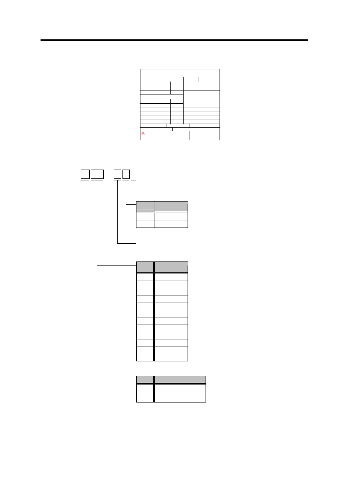
Introduction
Thank you for selecting the Mitsubishi numerical control unit.
This instruction manual describes the handling and caution points for using this AC
servo/spindle.
Incorrect handling may lead to unforeseen accidents, so always read this instruction
manual thoroughly to ensure correct usage.
Make sure that this instruction manual is delivered to the end user.
Always store this manual in a safe place.
In order to confirm if all function specifications described in this manual are applicable,
refer to the specifications for each CNC.
Notes on Reading This Manual
(1) Since the description of this specification manual deals with NC in general, for the
specifications of individual machine tools, refer to the manuals issued by the
respective machine manufacturers. The "restrictions" and "available functions"
described in the manuals issued by the machine manufacturers have precedence
to those in this manual.
(2) This manual describes as many special operations as possible, but it should be
kept in mind that items not mentioned in this manual cannot be performed.
Page 4
Precautions for safety
Please read this manual and auxiliary documents before starting installation, operation,
maintenance or inspection to ensure correct usage. Thoroughly understand the device, safety
information and precautions before starting operation.
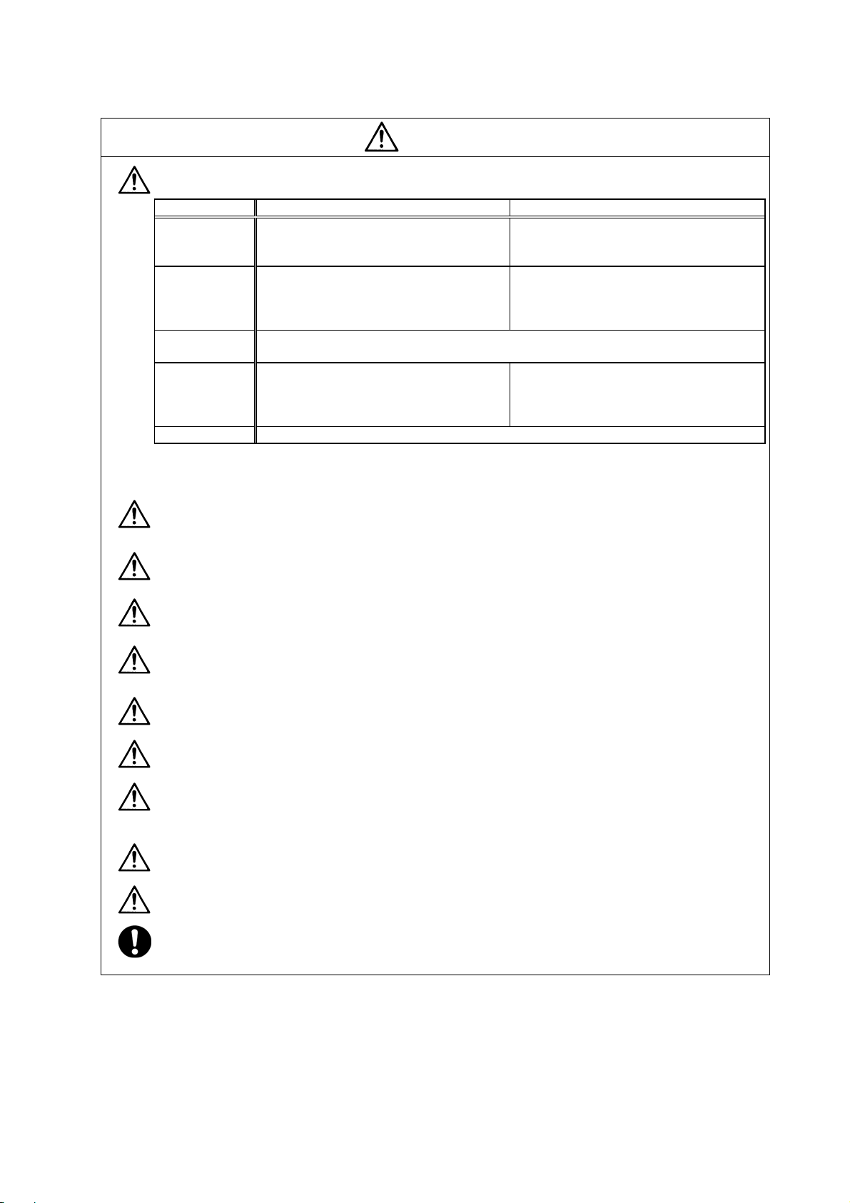
The safety precautions in this instruction manual are ranked as "WARNING" and "CAUTION".
Note that some items described as
the situation. In any case, important information that must be observed is described.
The signs indicating prohibited and mandatory matters are explained below.
DANGER
WARNING
CAUTION
When there is a potential risk of fatal or serious injuries if
handling is mistaken.
When a dangerous situation, or fatal or serious injuries may
occur if handling is mistaken.
When a dangerous situation may occur if handling is mistaken
leading to medium or minor injuries, or physical damage.
CAUTION
may lead to major results depending on
Indicates a prohibited matter. For example, "Fire Prohibited"
is indicated as .
Indicates a mandatory matter. For example, grounding is
indicated as
.
After reading this specifications and instructions manual, store it where the user can access it
easily for reference.
The numeric control unit is configured of the control unit, operation board, servo drive unit,
spindle drive unit, power supply, servomotor and spindle motor, etc.
In this section "Precautions for safety", the following items are generically called the "motor".
• Servomotor
• Linear servomotor
• Spindle motor
In this section "Precautions for safety", the following items are generically called the "unit".
• Servo drive unit
• Spindle drive unit
• Power supply unit
• Scale interface unit
• Magnetic pole detection unit
POINT
Important matters that should be understood for operation of this machine
are indicated as a POINT in this manual.
Page 5
1. Electric shock prevention
Do not open the front cover while the power is ON or during operation. Failure to observe this
could lead to electric shocks.
Do not operate the unit with the front cover removed. The high voltage terminals and charged
sections will be exposed, and can cause electric shocks.
Do not remove the front cover and connector even when the power is OFF unless carrying
out wiring work or periodic inspections. The inside of the units is charged, and can cause
electric shocks.
Since the high voltage is supplied to the main circuit connector while the power is ON or
during operation, do not touch the main circuit connector with an adjustment screwdriver o r
the pen tip. Failure to observe this could lead to electric shocks.
Wait at least 15 minutes after turning the power OFF, confirm that the CHARGE lamp has
gone out, and check the voltage between P and N terminals with a tester, etc., before starting
wiring, maintenance or inspections. Failure to observe this could lead to electric shocks.
Ground the unit and motor following the standards set forth by each country.
Wiring, maintenance and inspection work must be done by a qualified technician.
Wire the servo drive unit and servomotor after installation. Failure to observe this could lead to
electric shocks.
Do not touch the switches with wet hands. Failure to observe this could lead to electric shocks.
Do not damage, apply forcible stress, place heavy items on the cables or get them caught.
Failure to observe this could lead to electric shocks.
WARNING
2. Injury prevention
The linear servomotor uses a powerful magnet on the secondary side, and could adversely
affect pacemakers, etc.
During installation and operation of the machine, do not place portable items that could
malfunction or fail due to the influence of the linear servomotor's magnetic force.
Take special care not to pinch fingers, etc., when installing (and unpacking) the linear
servomotor.
In the system where the optical communication with CNC is executed, do not see directly the
light generated from CN1A/CN1B connector of drive unit or the end of cable. When the light
gets into eye, you may feel something is wrong for eye.
(The light source of optical communication corresponds to class1 defined in JIS C68 02 or
IEC60825-1.)
Page 6

1. Fire prevention
Install the units, motors and regenerative resistor on non-combustible material. Direct
installation on combustible material or near combustible materials could lead to fires.
Always install a circuit protector and contactor on the servo drive unit power input as explained
in this manual. Refer to this manual and select the correct circuit protector and contactor. An
incorrect selection could result in fire.
Shut off the power on the unit side if a fault occurs in the units. Fires could be caused if a large
current continues to flow.
When using a regenerative resistor, provide a sequence that shuts off the power with the
regenerative resistor's error signal. The regenerative resistor could abnormally overheat and
cause a fire due to a fault in the regenerative transistor, etc.
The battery unit could heat up, ignite or rupture if submerged in water, or if the poles are
incorrectly wired.
Cut off the main circuit power with the contactor when an alarm or emergency stop occurs.
2. Injury prevention
Do not apply a voltage other than that specified in this manual, on each terminal. Failure to
observe this item could lead to ruptures or damage, etc.
CAUTION
Do not mistake the terminal connections. Failure to observe this item could lead to ruptures or
damage, etc.
Do not mistake the polarity (
damage, etc.
Do not touch the radiation fin on unit back face, regenerative resistor or motor, etc., or place
parts (cables, etc.) while the power is turned ON or immediately after turning the power OFF.
These parts may reach high temperatures, and can cause burns or part damage.
Structure the cooling fan on the unit back face, etc., etc so that it cannot be touched after
installation. Touching the cooling fan during operation could lead to injuries.
+
,
). Failure to observe this item could lead to ruptures or
Page 7
CAUTION
3. Various precautions
Observe the following precautions. Incorrect handling of the unit could lead to faults, injuries and
electric shocks, etc.
(1) Transportation and installation
Correctly transport the product according to its weight.
Use the motor's hanging bolts only when transporting the motor. Do not transport the
machine when the motor is installed on the machine.
Do not stack the products above the tolerable number.
Follow this manual and install the unit or motor in a place where the weight can be borne.
Do not get on top of or place heavy objects on the unit.
Do not hold the cables, axis or detector when transporting the motor.
Do not hold the connected wires or cables when transporting the units.
Do not hold the front cover when transporting the unit. The unit could drop.
Always observe the installation directions of the units or motors.
Secure the specified distance between the units and control panel, or between the servo drive
unit and other devices.
Do not install or run a unit or motor that is damaged or missing parts.
Do not block the intake or exhaust ports of the motor provided with a cooling fan.
Do not let foreign objects enter the units or motors. In particular, if conductive objects such as
screws or metal chips, etc., or combustible materials such as oil enter, rupture or breakage
could occur.
The units and motors are precision devices, so do not drop them or apply strong impacts to
them.
Page 8
CAUTION
Store and use the units under the following environment conditions.
Environment
Ambient
temperature
Ambient
humidity
Atmosphere
Altitude
Vibration/impact
(Note 1) For details, confirm each unit or motor specifications in addition.
(Note 2) -15°C to 55°C for linear servomotor.
Operation: 0 to 55°C (with no freezing),
Storage / Transportation: -15°C to 70°C
Operation: 90%RH or less
(with no dew condensation)
Storage / Transportation: 90%RH or less
(with no dew condensation)
With no corrosive gas, inflammable gas, oil mist, dust or conductive fine particles
Operation/Storage: 1000 meters or less above
Transportation: 13000 meters or less above sea
Unit Motor
(with no freezing)
sea level,
level
According to each unit or motor specification
Operation: 0 to 40°C (with no freezing),
Storage: -15°C to 70°C
Operation: 80%RH or less
(with no dew condensation),
Storage: 90%RH or less
(with no dew condensation)
Indoors (no direct sunlight)
Operation: 1000 meters or less above sea level,
Storage: 10000 meters or less above sea level
(Note 2)
(with no freezing)
Securely fix the servomotor to the machine. Insufficient fixing could lead to the servomotor
slipping off during operation.
Always install the servomotor with reduction gear in the designated direction. Failure to do so
could lead to oil leaks.
Structure the rotary sections of the motor so that it can never be touched during operation.
Install a cover, etc., on the shaft.
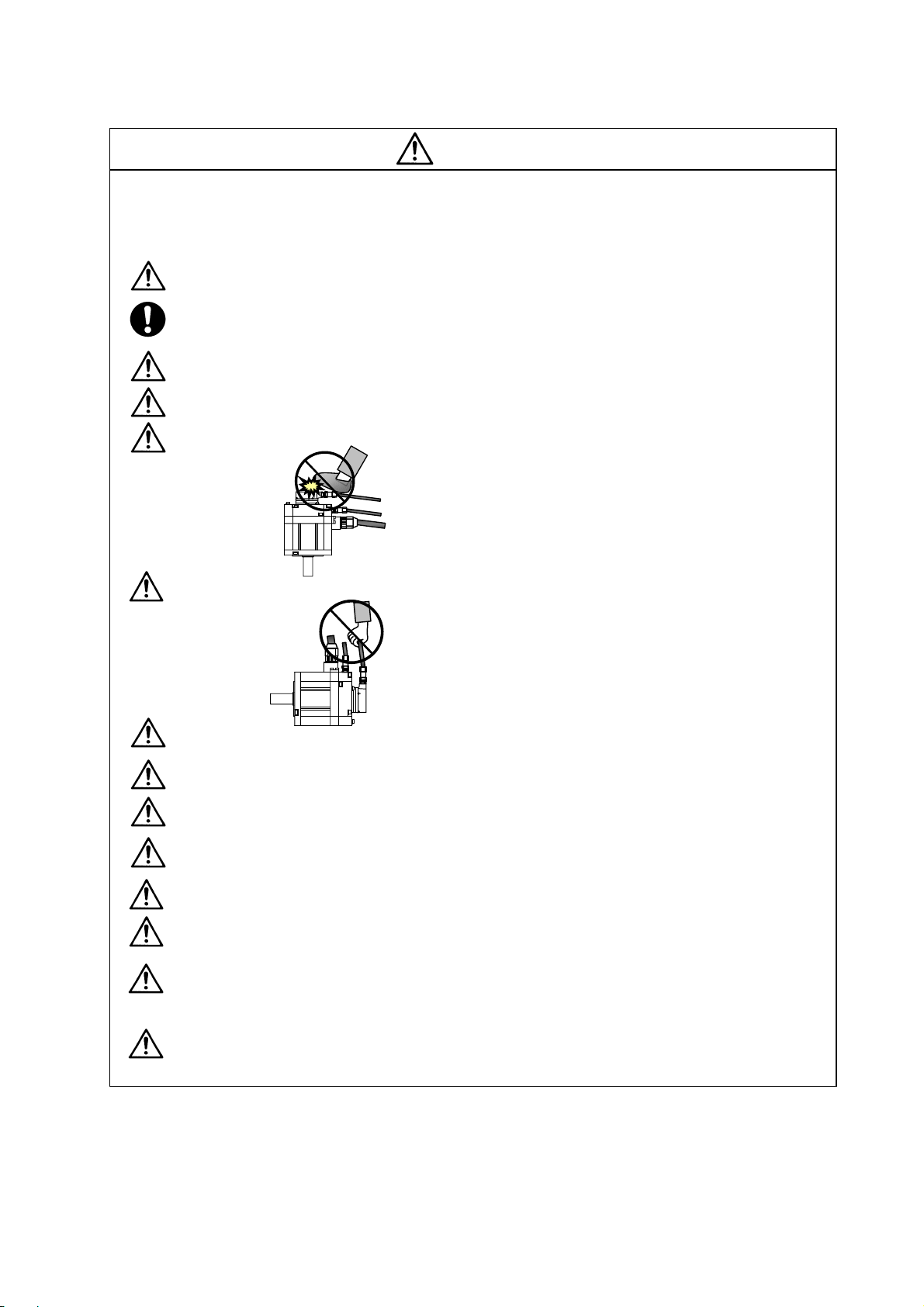
When installing a coupling to a servomotor shaft end, do not apply an impact by hammering,
etc. The detector could be damaged.
Do not apply a load exceeding the tolerable load onto the servomotor shaft. The shaft could
break.
Store the motor in the package box.
When inserting the shaft into the built-in IPM motor, do not heat the rotor higher than 130°C.
The magnet could be demagnetized, and the specifications characteristics will not be
ensured.
Always use a nonmagnetic tool (explosion-proof beryllium copper alloy safety tool: NGK
Insulators, etc.) when installing the linear servomotor.
Always provide a mechanical stopper on the end of the linear servomotor's travel path.
If the unit has been stored for a long time, always check the operation before starting actual
operation. Please contact the Service Center, Service Station, Sales Office or delayer.
Page 9
(2) Wiring
CAUTION
Correctly and securely perform the wiring. Failure to do so could lead to abnormal operation of
the motor.
Do not install a condensing capacitor, surge absorber or radio noise filter on the output side of
the drive unit.
Correctly connect the output side of the drive unit (terminals U, V, W). Failure to do so could
lead to abnormal operation of the motor.
When using a power regenerative power supply unit, always install an AC reactor for each
power supply unit.
In the main circuit power supply side of the unit, always install an appropriate circuit pro tector
or contactor for each unit. Circuit protector or contactor cannot be shared by several units.
Always connect the motor to the drive unit's output terminals (U, V, W).
Do not directly connect a commercial power supply to the servomotor. Failure to observe this
could result in a fault.
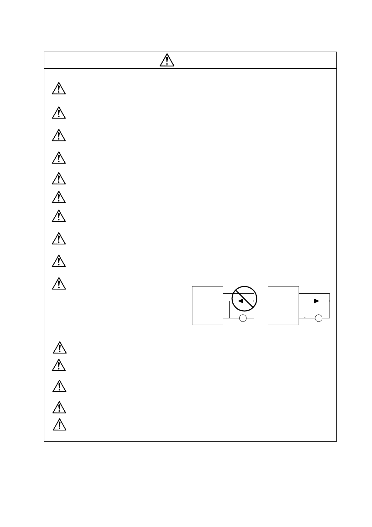
When using an inductive load such as a relay, always connect a diode as a noise measure
parallel to the load.
When using a capacitance load such as a lamp, always connect a protective resistor as a noise
measure serial to the load.
Do not reverse the direction of a diode
which connect to a DC relay for the
control output signals such as
Servodrive unit
COM
(24VDC)
Servodrive unit
COM
(24VDC)
contractor and motor brake output, etc.
to suppress a surge. Connecting it
backwards could cause the drive unit to
malfunction so that signals are not
Controloutput
signal
RA
Control output
signal
output, and emergency stop and other
safety circuits are inoperable.
RA
Do not connect/disconnect the cables connected between the units while the power is ON.
Securely tighten the cable connector fixing screw or fixing mechanism. An insecure fixing could
cause the cable to fall off while the power is ON.
When using a shielded cable instructed in the instruction manual, always ground the cable with
a cable clamp, etc.
Always separate the signals wires from the drive wire and power line.
Use wires and cables that have a wire diameter, heat resistance and flexibility that conforms to
the system.
Page 10
(3) Trial operation and adjustment
Check and adjust each program and parameter before starting operation. Failure to do so could
lead to unforeseen operation of the machine.
Do not make remarkable adjustments and changes of paramete r a s the ope ration could
become unstable.
The usable motor and unit combination is predetermined. Always check the models before
starting trial operation.
If the axis is unbalanced due to gravity, etc., balance the axis using a counterbalance, etc.
The linear servomotor does not have a stopping device such as magnetic brakes. Install a
stopping device on the machine side.
(4) Usage methods
In abnormal state, install an external emergency stop circuit so that the operation can be
stopped and power shut off immediately.
Turn the power OFF immediately if smoke, abnormal noise or odors are generated from the unit
or motor.
CAUTION
Do not disassemble or repair this product.
Never make modifications.
When an alarm occurs, the machine will start suddenly if an alarm reset (RST) is carried out
while an operation start signal (ST) is being input. Always confirm that the operation signal is
OFF before carrying out an alarm reset. Failure to do so could lead to accidents or injuries.
Reduce magnetic damage by installing a noise filter. The electronic devices used near the
unit could be affected by magnetic noise. Install a line noise filter, etc., if there is a risk of
magnetic noise.
Use the unit, motor and regenerative resistor with the designated combination. Failure to do so
could lead to fires or trouble.
The brake (magnetic brake) of the servomotor are for holding, and must not be used for normal
braking.
There may be cases when holding is not possible due to the magnetic brake's life, the machine
construction (when ball screw and servomotor are coupled via a timing belt, etc.) or the
magnetic brake’s failure. Install a stop device to ensure safety on the machine side.
After changing the programs/parameters or after maintenance and inspection, always test the
operation before starting actual operation.
Do not enter the movable range of the machine during automatic operation. Never place body
parts near or touch the spindle during rotation.
Follow the power supply specification conditions given in each specification for the power (input
voltage, input frequency, tolerable sudden power failure time, etc.).
Set all bits to "0" if they are indicated as not used or empty in the explanation on the bits.
Do not use the dynamic brakes except during the emergency stop. Continued use of the
dynamic brakes could result in brake damage.
If a circuit protector for the main circuit power supply is shared by several units, the circuit
protector may not activate when a short-circuit fault occurs in a small capacity unit. This is
dangerous, so never share the circuit protector.
Page 11
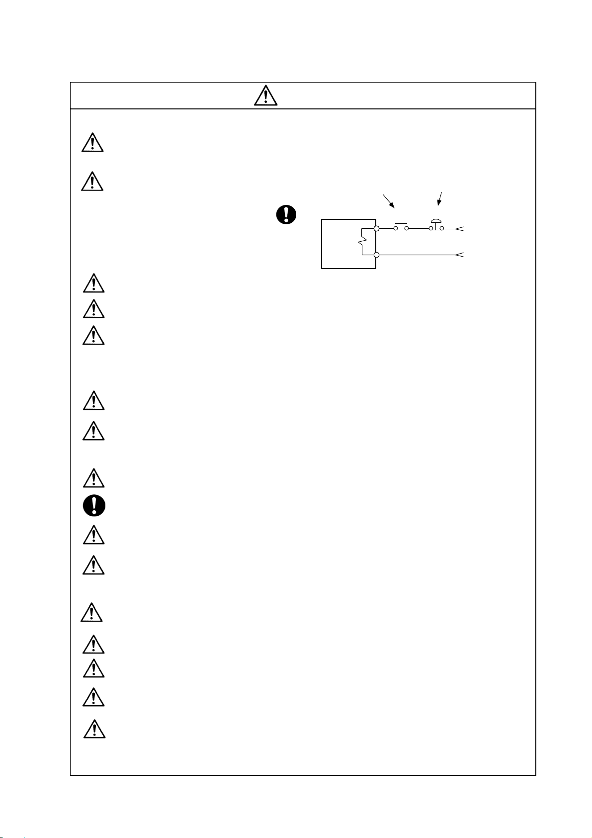
(5) Troubleshooting
If a hazardous situation is predicted during power failure or product trouble, use a servomotor
with magnetic brakes or install an external brake mechanism.
Use a double circuit configuration
that allows the operation circuit for
the magnetic brakes to be operated
even by the external emergency
stop signal.
CAUTION
Shut off with the servomotor
brake control output.
Servomotor
Magnetic
brake
Shut off with NC brake
control PLC output.
MBR
EMG
24VDC
Always turn the input power OFF when an alarm occurs.
If an alarm occurs, remove the cause, and secure the safety before resetting the alarm.
Never go near the machine after restoring the power after a power failure, as the machine
could start suddenly. (Design the machine so that personal safety can be ensured even if the
machine starts suddenly.)
(6) Maintenance, inspection and part replacement
Always backup the programs and parameters before starting maintenance or i nspections.
The capacity of the electrolytic capacitor will drop over time due to self-discharging, etc. To
prevent secondary disasters due to failures, replacing this part every five years when used
under a normal environment is recommended. Contact the Service Center, Service Station,
Sales Office or delayer for repairs or part replacement.
Do not perform a megger test (insulation resistance measurement) during inspections.
If the battery low warning is issued, back up the machining programs, tool data and
parameters with an input/output unit, and then replace the battery.
Do not short circuit, charge, overheat, incinerate or disassemble the battery.
The heat radiating fin used in some units contains substitute Freon as the refrigerant.Ta ke
care not to damage the heat radiating fin during maintenance and replacement work.
(7) Disposal
Do not dispose of this type of unit as general industrial waste. Always contact the Service
Center, Service Station, Sales Office or delayer for repairs or part replacement.
Do not disassemble the unit or motor.
Dispose of the battery according to local laws.
Always return the secondary side (magnet side) of the linear servomotor to the Service
Center or Service Station.
When incinerating optical communication cable, hydrogen fluoride gas or hydrogen chloride
gas which is corrosive and harmful may be generated. For disposal of optical communication
cable, request for specialized industrial waste disposal services that has incineration facility
for disposing hydrogen fluoride gas or hydrogen chloride gas.
Page 12

CAUTION
(8) Transportation
The unit and motor are precision parts and must be handled carefully.
According to a United Nations Advisory, the battery unit and battery must be transported
according to the rules set forth by the International Civil Aviation Organization (ICAO),
International Air Transportation Association (IATA), International Maritime Organization
(IMO), and United States Department of Transportation (DOT), etc.
(9) General precautions
The drawings given in this manual show the covers and safety partitions, etc., removed to provide a
clearer explanation. Always return the covers or partitions to their respective places before starting
operation, and always follow the instructions given in this manual.
Page 13

○ Treatment of waste ○
The following two laws will apply when disposing of this product. Considerations must be made to each
law. The following laws are in effect in Japan. Thus, when using this product overseas, the local laws will
have a priority. If necessary, indicate or notify these laws to the final user of the product.
1. Requirements for "Law for Promotion of Effective Utilization of Resources"
(1) Recycle as much of this product as possible when finished with use.
(2) When recycling, often parts are sorted into steel scraps and electric parts, etc., and sold to scrap
contractors. Mitsubishi recommends sorting the product and selling the members to appropriate
contractors.
2. Requirements for "Law for Treatment of Waste and Cleaning"
(1) Mitsubishi recommends recycling and selling the product when no longer needed according to
item (1) above. The user should make an effort to reduce waste in this manner.
(2) When disposing a product that cannot be resold, it shall be treat ed as a waste product.
(3) The treatment of industrial waste must be commissioned to a licensed industrial waste treatment
contractor, and appropriate measures, including a manifest control, must be taken.
(4) Batteries correspond to "primary batteries", and must be dispos ed of according to local disposal
laws.
Page 14

CONTENTS
1. Introduction
1-1 Servo/spindle drive system configuration............................................................................ 1-2
1-1-1 System configuration .....................................................................................................1-2
1-2 Explanation of type ..............................................................................................................1-3
1-2-1 Servomotor type ............................................................................................................ 1-3
1-2-2 Servo drive unit type...................................................................................................... 1-5
1-2-3 Spindle motor type......................................................................................................... 1-6
1-2-4 Spindle drive unit type ................................................................................................... 1-7
1-2-5 Power supply unit type .................................................................................................. 1-8
1-2-6 AC reactor type.............................................................................................................. 1-9
2. Specifications
2-1 Servomotor........................................................................................................................... 2-2
2-1-1 Specifications list ........................................................................................................... 2-2
2-1-2 Torque characteristics ...................................................................................................2-5
2-2 Spindle motor....................................................................................................................... 2-8
2-2-1 Specifications................................................................................................................. 2-8
2-2-2 Output characteristics.................................................................................................. 2-12
2-3 Drive unit ............................................................................................................................2-16
2-3-1 Installation environment conditions ............................................................................. 2-16
2-3-2 Servo drive unit............................................................................................................ 2-16
2-3-3 Spindle drive unit ...................................................................................................... ...2-17
2-3-4 Power supply unit ........................................................................................................ 2-17
2-3-5 AC reactor .................................................................................................................... 2-18
2-3-6 D/A output specifications for servo drive unit.............................................................. 2-19
2-3-7 D/A output specifications for spindle drive unit ...........................................................2-22
2-3-8 Explanation of each part.............................................................................................. 2-25
3. Characteristics
3-1 Servomotor........................................................................................................................... 3-2
3-1-1 Environmental conditions .............................................................................................. 3-2
3-1-2 Quakeproof level............................................................................................................ 3-2
3-1-3 Shaft characteristics ...................................................................................................... 3-3
3-1-4 Oil / water standards...................................................................................................... 3-4
3-1-5 Magnetic brake .............................................................................................................. 3-5
3-1-6 Dynamic brake characteristics ...................................................................................... 3-8
3-2 Spindle motor..................................................................................................................... 3-10
3-2-1 Environmental conditions ............................................................................................ 3-10
3-2-2 Shaft characteristics .................................................................................................... 3-10
3-3 Drive unit characteristics.................................................................................................... 3-11
3-3-1 Environmental conditions ............................................................................................ 3-11
3-3-2 Heating value............................................................................................................... 3-12
3-3-3 Overload protection characteristics............................................................................. 3-13
3-3-4 Drive unti arrangement ................................................................................................ 3-21
4. Dedicated options
4-1 Servo options ....................................................................................................................... 4-2
4-1-1 Dynamic brake unit (MDS-D-DBU) (mandatory selection for large capacity).............. 4-5
4-1-2 Battery option (MDS-A-BT, FCU6-BTBOX-36, ER6V-C119B, A6BAT)....................... 4-7
4-1-3 Ball screw side detector (OSA105-ET2, OSA166-ET2) ............................................. 4-15
4-1-4 Machine side detector ................................................................................................. 4-17
Page 15

4-2 Spindle options .................................................................................................................. 4-21
4-2-1 Spindle side detector (OSE-1024-3-15-68, OSE-1024-3-15-68-8)............................ 4-22
4-2-2 C axis detector (HEIDENHAIN ERM280) ................................................................... 4-24
4-3 Detector interface unit........................................................................................................ 4-26
4-3-1 MDS-B-HR................................................................................................................... 4-26
4-3-2 APE391M..................................................................................................................... 4-28
4-3-3 MJ831 .......................................................................................................................... 4-29
4-3-4 MDS-B-SD (Signal divided unit).................................................................................. 4-30
4-4 Drive unit option................................................................................................................. 4-32
4-4-1 DC connection bar....................................................................................................... 4-32
4-4-2 Side face protection cover........................................................................................... 4-33
4-5 Cables and connectors...................................................................................................... 4-34
4-5-1 Cable connection diagram........................................................................................... 4-34
4-5-2 List of cables and connectors...................................................................................... 4-35
4-5-3 Optical communication cable specifications ............................................................... 4-40
5. Selection of peripheral devices
5-1 Selection of wire................................................................................................................... 5-2
5-1-1 Example of wires by unit................................................................................................ 5-2
5-2 Selection of circuit protector and contactor ......................................................................... 5-5
5-2-1 Selection of circuit protector ..........................................................................................5-5
5-2-2 Selection of contactor.................................................................................................... 5-6
5-3 Selection of earth leakage breaker...................................................................................... 5-7
5-4 Branch-circuit protection (for control power supply)............................................................ 5-8
5-4-1 Circuit protection............................................................................................................ 5-8
5-4-2 Fuse protection ..............................................................................................................5-8
5-5 Noise filter ............................................................................................................................ 5-9
5-6 Surge absorber .................................................................................................................. 5-10
5-7 Relay .................................................................................................................................. 5-11
Appendix 1. Outline dimension drawings
Appendix 1-1 Outline dimension drawings of servomotor.......................................................A1-2
Appendix 1-1-1 HF-H motor..................................................................................................A1-2
Appendix 1-1-2 HP-H motor................................................................................................A1-11
Appendix 1-1-3 HC-H motor ...............................................................................................A1-16
Appendix 1-2 Outline dimension drawings of spindle motor.................................................A1-17
Appendix 1-3 Outline dimension drawings of unit.................................................................A1-29
Appendix 1-3-1 Servo drive unit..........................................................................................A1-29
Appendix 1-3-2 Spindle drive unit.......................................................................................A1-36
Appendix 1-3-3 Power supply unit ......................................................................................A1-42
Appendix 1-3-4 Installation position of drive unit cooling fan.............................................A1-45
Appendix 1-3-5 AC reactor .................................................................................................A1-47
Appendix 2. Cable and Connector Specifications
Appendix 2-1 Selection of cable ..............................................................................................A2-2
Appendix 2-1-1 Cable wire and assembly............................................................................A2-2
Appendix 2-2 Cable connection diagram.................................................................................A2-4
Appendix 2-3 Main circuit cable connection diagram............................................................A2-14
Appendix 2-4 Connector outline dimension drawings...........................................................A2-15
Appendix 2-5 Cable and connector assembly.......................................................................A2-27
Appendix 2-5-1 CM10-SP**S plug connector.....................................................................A2-27
Appendix 2-5-2 CM10-AP**S Angle Plug Connector.........................................................A2-34
Page 16

Appendix 3. Selection
Appendix 3-1 Selection of the servomotor series....................................................................A3-2
Appendix 3-1-1 Motor series characteristics ........................................................................ A3-2
Appendix 3-1-2 Servomotor precision ..................................................................................A3-2
Appendix 3-1-3 Selection of servomotor capacity................................................................A3-3
Appendix 3-1-4 Motor shaft conversion load torque.............................................................A3-6
Appendix 3-1-5 Expressions for load inertia calculation.......................................................A3-7
Appendix 3-2 Selection of the power supply unit ....................................................................A3-8
Appendix 3-2-1 Calculation of spindle output.......................................................................A3-8
Appendix 3-2-2 Calculation of servo motor output...............................................................A3-9
Appendix 3-2-3 Selection of the power supply unit............................................................A3-10
Appendix 3-2-4 Required capacity of power supply...........................................................A3-11
Appendix 3-2-5 Example for power supply unit and power supply facility capacity...........A3-12
Appendix 4. Transportation Restrictions for Lithium Batteries
Appendix 4-1 Restriction for packing.......................................................................................A4-2
Appendix 4-1-1 Target products ...........................................................................................A4-2
Appendix 4-1-2 Handling by user .........................................................................................A4-3
Appendix 4-1-3 Reference....................................................................................................A4-4
Appendix 4-2 Issuing domestic law of the United State for primary lithium battery
transportation ....................................................................................................A4-5
Appendix 4-2-1 Outline of regulation ....................................................................................A4-5
Appendix 4-2-2 Target products ...........................................................................................A4-5
Appendix 4-2-3 Handling by user .........................................................................................A4-5
Appendix 4-2-4 Reference....................................................................................................A4-5
Appendix 4-3 Example of hazardous goods declaration list...................................................A4-6
Appendix 5. Compliance to EC Directives
Appendix 5-1 Compliance to EC Directives ............................................................................A5-2
Appendix 5-1-1 European EC Directives..............................................................................A5-2
Appendix 5-1-2 Cautions for EC Directive compliance........................................................A5-2
Appendix 6. EMC Installation Guidelines
Appendix 6-1 Introduction ........................................................................................................A6-2
Appendix 6-2 EMC instructions ...............................................................................................A6-2
Appendix 6-3 EMC measures..................................................................................................A6-3
Appendix 6-4 Measures for panel structure.............................................................................A6-3
Appendix 6-4-1 Measures for control panel unit...................................................................A6-3
Appendix 6-4-2 Measures for door .......................................................................................A6-4
Appendix 6-4-3 Measures for operation board panel...........................................................A6-4
Appendix 6-4-4 Shielding of the power supply input section................................................A6-4
Appendix 6-5 Measures for various cables.............................................................................A6-5
Appendix 6-5-1 Measures for wiring in panel.......................................................................A6-5
Appendix 6-5-2 Measures for shield treatment.....................................................................A6-5
Appendix 6-5-3 Servo/spindle motor power cable................................................................A6-6
Appendix 6-5-4 Servo/spindle motor feedback cable...........................................................A6-7
Appendix 6-6 EMC countermeasure parts ..............................................................................A6-8
Appendix 6-6-1 Shield clamp fitting ......................................................................................A6-8
Appendix 6-6-2 Ferrite core ..................................................................................................A6-9
Appendix 6-6-3 Power line filter..........................................................................................A6-10
Appendix 6-6-4 Surge protector..........................................................................................A6-17
Page 17

Appendix 7. EC Declaration of conformity
Appendix 7-1 Compliance to EC Directives ............................................................................A7-2
Appendix 7-1-1 Low voltage equipment ...............................................................................A7-2
Appendix 7-1-2 EMC Directive (Electromagnetic compatibility).........................................A7-11
Appendix 8. Instruction Manual for Compliance with UL/c-UL Standard
Appendix 8.1 Operation surrounding air ambient temperature...............................................A8-2
Appendix 8.2 Notes for AC servo/spindle system...................................................................A8-2
Appendix 8.2.1 General Precaution......................................................................................A8-2
Appendix 8.2.2 Installation....................................................................................................A8-2
Appendix 8.2.3 Short-circuit ratings......................................................................................A8-2
Appendix 8.2.4 Capacitor discharge time.............................................................................A8-2
Appendix 8.2.5 Peripheral devices .......................................................................................A8-3
Appendix 8.2.6 Field Wiring Reference Table for Input and Output ....................................A8-3
Appendix 8.2.7 Motor Over Load Protection........................................................................A8-4
Appendix 8.2.8 Flange of servo motor..................................................................................A8-4
Appendix 8.2.9 Spindle Drive / Motor Combinations............................................................A8-5
Appendix 8.3 AC Servo/Spindle System Connection..............................................................A8-6
Appendix 8.3.1 MDS-D/DH-V/SP Series..............................................................................A8-6
Appendix 8.3.2 MDS-D-SVJ3/SPJ3 Series ..........................................................................A8-6
Appendix 9. Compliance with China Compulsory Product Certification (CCC Certification)
System
Appendix 9-1 Outline of China Compulsory Product Certification System.............................A9-2
Appendix 9-2 First Catalogue of Products subject to Compulsory Product Certification........A9-2
Appendix 9-3 Precautions for Shipping Products....................................................................A9-3
Appendix 9-4 Application for Exemption..................................................................................A9-4
Appendix 9-5 Mitsubishi NC Product Subject to/Not Subject to CCC Certification................A9-5
Page 18

1. Introduction
1-1 Servo/spindle drive system configuration ..........................................................................................1-2
1-1-1 System configuration...................................................................................................................1-2
1-2 Explanation of type............................................................................................................................. 1-3
1-2-1 Servomotor type..........................................................................................................................1-3
1-2-2 Servo drive unit type.................................................................................................................... 1-5
1-2-3 Spindle motor type ......................................................................................................................1-6
1-2-4 Spindle drive unit type................................................................................................................. 1-7
1-2-5 Power supply unit type................................................................................................................1-8
1-2-6 AC reactor type ...........................................................................................................................1-9
1 - 1
Page 19
t
t
r
A
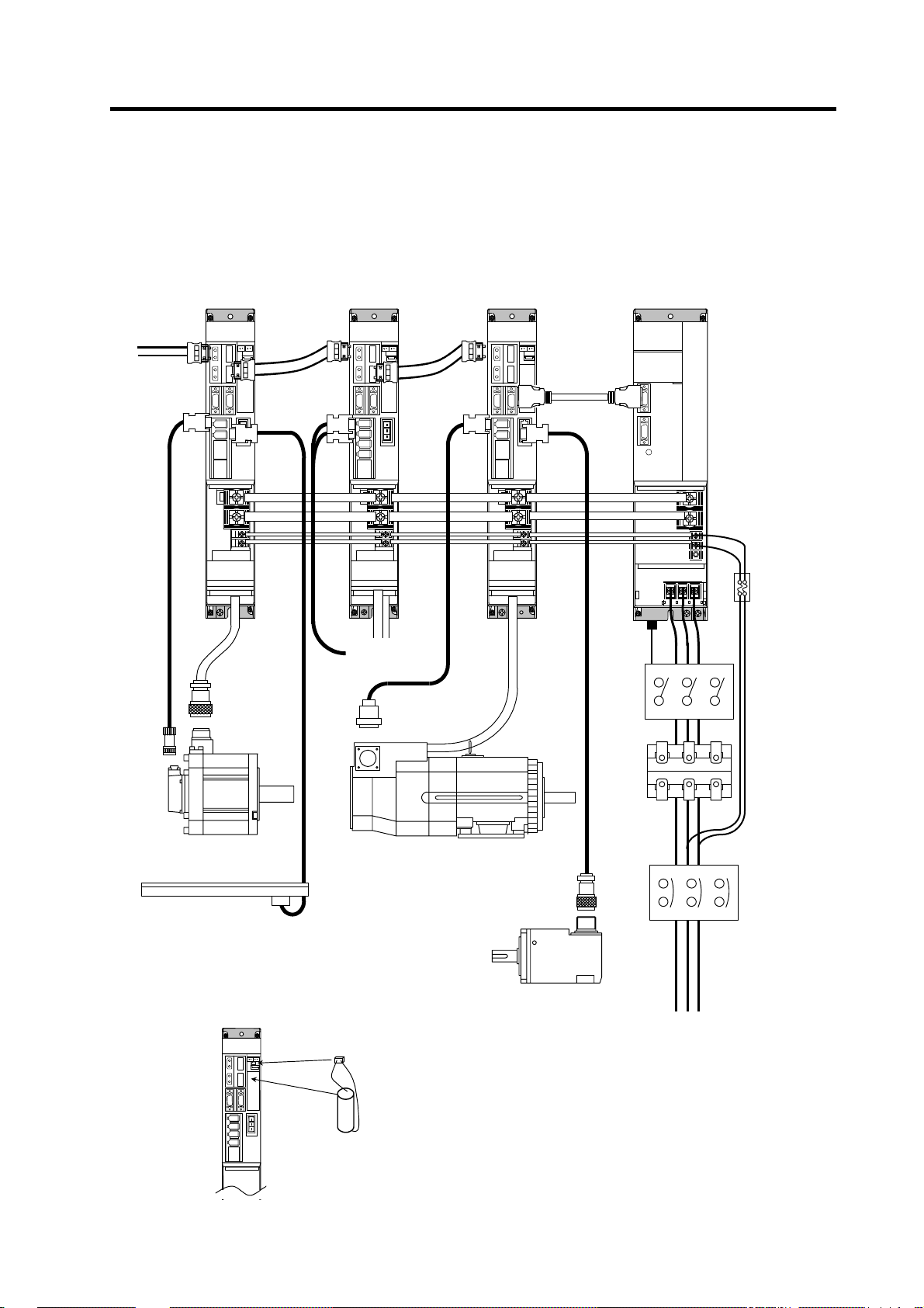
1. Introduction
1-1 Servo/spindle drive system configuration
1-1-1 System configuration
1-axis servo drive uni
From NC
L+
L-
(MDS-DH-V1)
2-axis servo drive uni
(MDS-DH-V2)
Spindle drive unit
(MDS-DH-SP)
Power supply unit
(MDS-DH-CV)
To 2nd and 3rd
axis servo
Servomotor Spindle motor
Linear scale
(for full closed control)
(Note) Prepared by user
Cell battery
built in drive unit
(ER6V-C119B)
Spindle side detecto
Circuit protector
or
Protection fuse
(Note)
Prepared by
user
Contactor
(Note)
Prepared by
user
C reactor
(DH-AL)
Circuit protector
(Note)
Prepared by
user
3-phase 400VAC power supply
In addition to the cell bat tery in the above, the
external battery unit (MDS- A-BT) can be also
used.
1 - 2
Page 20
1. Introduction
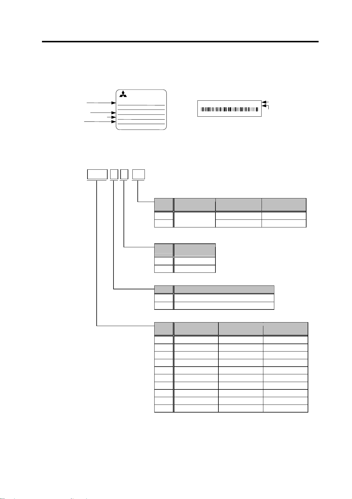
1-2 Explanation of type
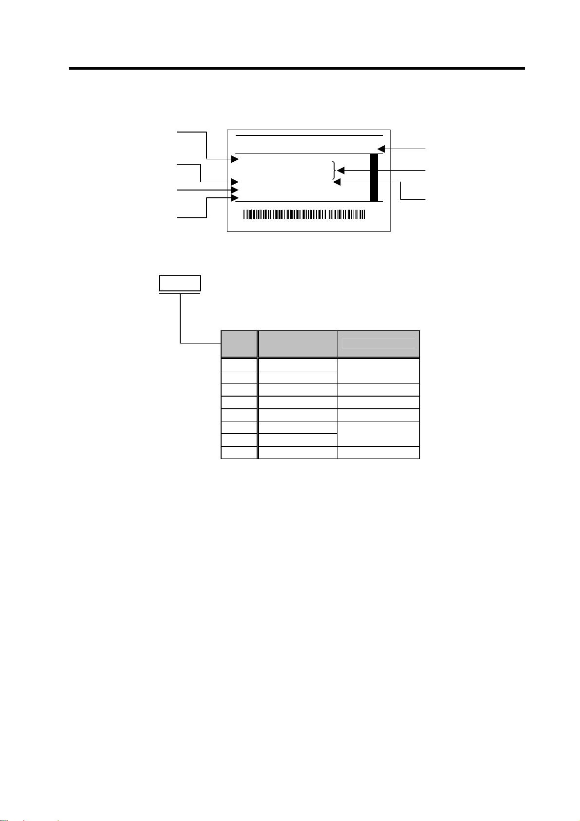
1-2-1 Servomotor type
Motor type
Rated output
Rated rotation speed
Serial No.
(1) HF-H Series
HF-H
(4) Detector
A51 1,000,000 p/rev OSA105S5
A74
(3) Shaft end structure
S Straight
T Taper
(2) Magnetic brakes
None None
B With magnetic brakes
(1) Rated output • Maximum rotation speed
75 0.75 kW 5000 r/min □90 mm
105 1.0 kW 5000 r/min □90 mm
54 0.5 kW 4000 r/min □130 mm
104 1.0 kW 4000 r/min □130 mm
154 1.5 kW 4000 r/min □130 mm
204 2.0 kW 4000 r/min □176 mm
354 3.5 kW 4000 r/min □176 mm
453 4.5 kW 3500 r/min □176 mm
703 7.0 kW 3000 r/min □176 mm
903 9.0 kW 3000 r/min □204 mm
(1) (2) (3) - (4)
MITSUBISHI
AC SERVO MOTOR
HF-HxxxBS
INPUT 3AC 456 V xxx A
x.x
OUTPUT
3000r/min
SER.No.
MITSUBISHI ELECTRIC
MADE IN JAPAN
kW
IP65 CI.F xx kg
xxxxxxxx*
IEC34-1 1994
DATE
04-1
00395298-01
Motor rating nameplate
Symbol
Symbol
Symbol
Symbol Rated output
ROTARY DETECTOR OSA166S5
SER. X X X X X X X X X X X DATE 0401
A2
Detector rating nameplate
Detection
method
Absolute position
Shaft end
structure
Magnetic brakes
Detector type
MITSUBISHI ELECTRIC CORP.
MADE IN JAPAN
Serial No.
D
Resolution Detector type
16,000,000 p/rev OSA166S5
(Note)
"Taper" is available for the motor whose
flange size is □90mm or □130mm.
Maximum rotation
speed
Flange size
1 - 3
Page 21
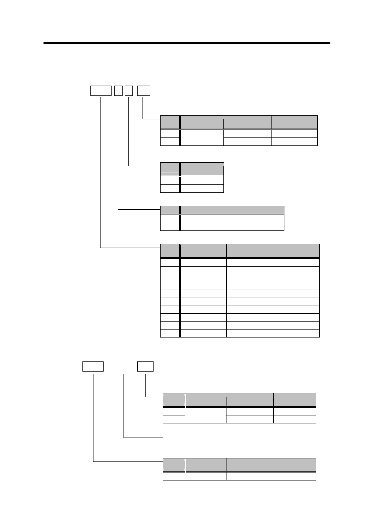
1. Introduction
(2) HP-H Series
HP-H
(4) Detector
A51 1,000,000 p/rev OSA105S5
A74
(3) Shaft end structure
S Straight
T Taper
(2) Magnetic brakes
None None
B With magnetic brakes
(1) Rated output • Maximum rotation speed
54 0.5 kW 4000 r/min □130 mm
104 1.0 kW 4000 r/min □130 mm
154 1.5 kW 4000 r/min □130 mm
224 2.2 kW 4000 r/min □130 mm
204 2.0 kW 4000 r/min □180 mm
354 3.5 kW 4000 r/min □180 mm
454 4.5 kW 4000 r/min □180 mm
704 7.0 kW 4000 r/min □180 mm
903 9.0 kW 3000 r/min □220 mm
1103 11.0 kW 3000 r/min □220 mm
(1) (2) (3) - (4)
Symbol
Symbol
Symbol
Symbol Rated output
Detection
method
Absolute position
Shaft end
structure
Magnetic brakes
Resolution Detector type
16,000,000 p/rev OSA166S5
(Note)
"Taper" is available for the motor whose
flange size is □130mm.
Maximum rotation
speed
Flange size
(3) HC-H Series
HC-H
(2) Detector
A51 1,000,000p/rev OSA105S5
A74
(1) Rated output • Maximum rotation speed
1502 15.0kW 2500r/min □280 mm
(1)
S- S10 -
(2)
Symbol
Compatible with DH series
Symbol Rated output
Detection
method
Absolute
position
1 - 4
Resolution Detector type
16,000,000p/rev OSA166S5
Maximum
rotation speed
Flange size
Page 22
1. Introduction
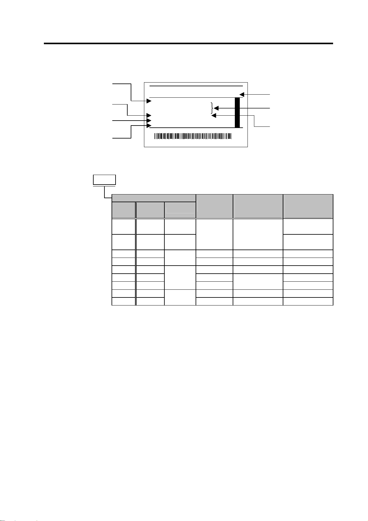
1-2-2 Servo drive unit type
Output
Applicable standard
Software No.
Serial No.
MDS-DH-
(1) Type
MDS-DH-
V1-10 10A
V1-20 20A
V1-40 40A
V1-80 80A
V1-80W 80A 90mm
V1-160 160A 120mm
V1-160W 160A 150mm
V1-200 200A 240mm
1-axis servo drive unit Compatible motor
Nominal
maximum
current
(Note) DC connection bar is required. Always install a large capacity drive unit in the left side of power supply unit, and connect with
DC connection bar.
§ Indicates the compatible motor for each servo drive unit.
2-axis servo drive unit Compatible motor
(1) Type
MDS-DH-
V2-1010 10+10A LM
V2-2010 20+10A
V2-2020 20+20A LM
V2-4020 40+20A
V2-4040 40+40A
V2-8040 80+40A
V2-8080 80+80A
Nominal
maximum
current
§ Indicates the compatible motor for each servo drive unit.
(1)
Unit
width
75 105 54 104 154 204 354 453 703 903 54 104 154 224 204 354 454 704 903 1103 1502S-S10
§ §
60mm
(Note)
Unit width Axis
60mm
90mm
MITSUBISHI
TYPE
POWER 9.0kW
INPUT 6A DC513-648V
0.1A 1PH380-440/380-480V 50/60Hz
OUTPUT 15A 3PH 456V 0-240Hz
EN50178 MANUAL #IB11500002
S/W BND5xxW000A0 H/W VER. *
SERIAL# HVACQFXJK50 DATE 04/01
MITSUBISHI ELECTRIC CORPORATION JAPAN
* H V A C Q F X J K 5 0 % *
Rating nameplate
HF-H HP-H
§ § § §
§ § § § §
75 105 54 104 154 204 354 453 703 903 54 104 154 224 204 354 454 704 903 1103
§ §
L
§ §
M
L
M
LM
L
M
LM
§ §
§ §
§ §
§ §
SERVO DRIVE UNIT
MDS-DH-V1-80
Type
Input/output conditions
Manual No.
§
§
HF-H HP-H
§ §
§ §
§ §
§ §
§ §
§
§
§ §
§ §
§ §
§ §
§ § §
§ § §
§ § §
§ §
§ §
§
HC-H
§
□
CAUTION
The dynamic brake unit (MDS-D-DBU) is required for the MDS-DH-V1-160W or
larger.
1 - 5
Page 23
1. Introduction
1-2-3 Spindle motor type
(1) Standard spindle motor series
MITSUBISHI AC SPINDLE MOTOR
TYPE
SJ-4-V5.5-01T
SI CONT 4 POLE
kW r/min
3.7 1500-6000 25 P OWE R FAC TOR 82 %
2.8 8000 17
S2 30 min S3 50 %
kW r/min
5.5 1500-6000 33
4.1 8000 23 INSULATION CLASS F
A MB TEMP. 0-40ºC
SERIAL
DATE
FRAME D90F WEIGHT 49 kg IP 44
IEC 34-1 1994 SPEC No.RSV00023*
MITSUBISHI ELECTRIC CORPORATION
A (~)
WIND CONNECT
max
MOTOR INPUT (
137 - 162 V
A (~)
AMP INPUT (
max
200-230V 50/60Hz
MADE IN JAPAN
A19103-01
Rating nameplate
3 PHASES
)
~
)
~
U
995291-01
SJ-4-
(1) (2)
(4) Special specifications
None
Z
(3) Specification code
(2) Short time rated output
2.2 2.2 kW
3.7 3.7 kW
5.5 5.5 kW
7.5 7.5 kW
11 11 kW
15 15 kW
18.5 18.5 kW
22 22 kW
26 26 kW
37 37 kW
45 45 kW
55 55 kW
(1) Motor series
VS
-
(3) (4)
T
For MDS-DH motor
Symbol
The SJ-4-V Series is indicated with a specification code (01 to 99).
Symbol
Symbol Motor series
V
Special
specifications
None
High-speed
Short time
rated output
(Note)
For the short time rated output of the wide range
constant output, high-speed and hollow shaft series,
refer to the specifications of each spindle motor.
Compact medium to
large capacity
Hollow shaft
(Note) The built-in spindle motor is available by special order.
1 - 6
Page 24
t
1. Introduction
1-2-4 Spindle drive unit type
Outpu
Applicable standard
Software No.
Serial No.
MDS-DH
(1) Capacity
SP-20 20A
SP-40 40A
SP-80 80A 90mm wide
SP-100 100A 120mm wide
SP-160 160A 150mm wide
SP-200 200A
SP-320 320A
SP-480 480A 300mm wide (Note)
(1)
-
MITSUBISHI
TYPE
POWER 37kW
INPUT 99A DC513-648V
0.1A 1PH380-440/380-480V 50/60Hz
OUTPUT 85A 3PH 340V 0-1167Hz
EN50178 MANUAL #IB1500003
S/W BND5xxW000A0 H/W VER. *
SERIAL# HV A79G06K 0R DATE 04/01
MITSUBISHI ELECTRIC CORPORATION JAPAN
* H V A 7 9 G 0 6 K 0 R G *
Rating nameplate
Symbol
(Note) DC connection bar is required. Always install a large capacity
Nominal maximum
current
drive unit in the left side of power supply unit, and connect with
DC connection bar.
SERVO DRIVE UNIT
MDS-DH-SP-200
Unit width
60mm wide
240mm wide (Note)
Type
Input/output conditions
Manual No.
1 - 7
Page 25
t
1-2-5 Power supply unit type
Outpu
Applicable standard
Software No.
Serial No.
MDS-DH-
CV-110 11.0 kW DH-AL-11K S-N21-AC400V NF63-CW3P-30A
CV-185 18.5 kW
CV-300 30.0 kW DH-AL-30K S-N50-AC400V NF125-CW3P-75A
CV-370 37.0 kW DH-AL-37K NF125-CW3P-100A
CV-450 45.0 kW
CV-550 55.0 kW DH-AL-55K S-N80-AC400V NF250-CW3P-150A
CV-750 75.0 kW
(1)
Power supply unit
(1) Type
MDS-DH-
CV-37
CV-75
(Note 1) This is an optional part, and must be prepared by the user.
(Note 2) When connecting with a large capacity drive unit, DC connection bar is required. Always install
a large capacity drive unit in the left side of power supply unit, and connect with DC connection
bar.
1. Introduction
MITSUBISHI
TYPE
POWER 37kW
INPUT 87A 3PH 380- 440/480V 50/60Hz
0.1A 1PH 380- 440/480V 50/60Hz
OUTPUT 99A DC513-648V
EN50178 MANUAL #IB1500003
S/W BND5xxW000A0 H/W VER. *
SERIAL# HVA3EG1796L DATE 04/01
MITSUBISHI ELECTRIC CORPORATION JAPAN
* H V A 3 E G 1 7 9 6 L M *
Rating nameplate
Rated
output
3.7 kW
7.5 kW
Unit width
Under
development
Under
development
90mm wide
150mm wide
(Note 2)
300mm wide
(Note 2)
SERVO DRIVE UNIT
MDS-DH-CV-450
Type
Input/output conditions
Manual No.
Compatible
AC reactor
DH-AL-7.5K S-N12-AC400V
DH-AL-18.5K S-N25-AC400V NF63-CW3P-50A
DH-AL-45K
DH-AL-75K S-N150-AC400V NF250-CW3P-200A
Compatible
contactor
(Mitsubishi)
(Note 1)
S-N65-AC400V
Compatible
circuit protector
(Mitsubishi)
(Note 1)
NF63-CW3P-10A
NF63-CW3P-20A
NF125-CW3P-125A
1 - 8
Page 26
1-2-6 AC reactor type
Type
DH-AL-
11K 11.0 kW MDS-DH-CV-110
18.5K 18.5 kW MDS-DH-CV-185
30K 30.0 kW MDS-DH-CV-300
37K 37.0 kW MDS-DH-CV-370
45K 45.0 kW MDS-DH-CV-450
55K 55.0 kW MDS-DH-CV-550
75K 75.0 kW MDS-DH-CV-750
DH-AL-18.5K
Nameplate
(1)
Top surf ace of AC reactor
AC reactor
(1) Type
DH-AL-
7.5K 7.5 kW
Capacity
1. Introduction
Compatible power
supply unit
MDS-DH-CV-37
MDS-DH-CV-75
1 - 9
Page 27

2. Specifications
2-1 Servomotor.........................................................................................................................................2-2
2-1-1 Specifications list.........................................................................................................................2-2
2-1-2 Torque characteristics.................................................................................................................2-5
2-2 Spindle motor.....................................................................................................................................2-8
2-2-1 Specifications .............................................................................................................................. 2-8
2-2-2 Output characteristics................................................................................................................2-12
2-3 Drive unit..........................................................................................................................................2-16
2-3-1 Installation environment conditions........................................................................................... 2-16
2-3-2 Servo drive unit .........................................................................................................................2-16
2-3-3 Spindle drive unit.......................................................................................................................2-17
2-3-4 Power supply unit...................................................................................................................... 2-17
2-3-5 AC reactor ................................................................................................................................. 2-18
2-3-6 D/A output specifications for servo drive unit............................................................................2-19
2-3-7 D/A output specifications for spindle drive unit .........................................................................2-22
2-3-8 Explanation of each part............................................................................................................2-25
2 - 1
Page 28
2. Specifications
2-1 Servomotor
2-1-1 Specifications list
HF-H Series
HF-H Series
Servomotor type
Compatible servo drive
unit type
Rated output [kW] 0.75 1.0 0.5 1.0 1.5 2.0 3.5 4.5 7.0 9.0
Continuous
characteristics
Rated rotation speed [r/min] 4000 3000
Maximum rotation speed [r/min] 5000 4000 3500 3000
Maximum current [A] 7.0 7.75 8.4 14.5 26.0 28.5 58.0 52.1 54.2 102.0
Maximum torque [N·m] 8.0 11.0 13.0 23.3 42.0 47.0 90.0 122.0 152.0 208.0
Power rate at continuous
rated torque
Motor inertia [kg·cm2] 2.6 5.1 6.1 11.9 17.8 38.3 75.0 112.0 154.0 196.0
Motor inertia with brake [kg·cm2] 2.8 5.3 8.3 14.1 20.0 48.0 84.7 121.7 163.7 205.7
Maximum motor shaft conversion load
inertia ratio
Motor side detector
Structure Fully closed, self-cooling (Protection method: IP67) (Note3)
Environment
Weight
Without/with brake
Armature insulation class Class F
Rated current [A] 1.4 1.8 0.9 1.8 2.9 3.4 6.9 6.7 8.3 13.6
Rated torque [N·m] 1.8 2.4 1.6 3.2 4.8 6.4 11.1 14.3 22.3 28.7
Stall current [A] 1.6 2.3 1.6 3.3 5.5 7.3 14.0 17.0 18.2 28.0
Stall torque [N·m] 2.0 3.0 2.9 5.9 9.0 13.7 22.5 37.2 49.0 58.8
Ambient temperature
Ambient humidity
Atmosphere Indoors (no direct sunlight); no corrosive gas, inflammable gas, oil mist, or dust
Altitude
Vibration X: 19.6m/s
MDS-DH-V1/2- 10 10 20 20 40 40 80 80 80W 160
[kW/s] 12.3 11.2 4.1 8.4 12.7 10.6 16.5 18.3 32.2 42.1
[kg]
HF-H
HF-H
75
105
High-speed, high-accuracy machine : 3 times or less of motor inertia
General machine tool (interpolation axis) : 5 times or less of motor inertia
General machine (non-interpolation axis) : 7 times or less of motor inertia
2.5/
3.9
4.3/
5.7
ABS specifications: HF-H-A74/-A51
HF-H
A74: 16,000,000 pulse/rev, A51: 1,000,000 pulse/rev
Operation: 80%RH or less (with no dew condensation),
Storage: 90%RH or less (with no dew condensation)
HF-H
54
104
Resolution per motor revolution
Operation: 0 to 40°C (with no freezing),
Storage: -15°C to 70°C (with no freezing)
Operation: 1000 meters or less above sea level,
Storage: 10000 meters or less above sea level
4.8/
6.5/
6.8
8.5
HF-H
154
2
8.3/
10.3
HF-H
(2G) Y: 19.6m/s2 (2G)
12.0/
18.0
204
HF-H
354
19.0/
25.0
HF-H
453
26.0/
32.0
HF-H
703
32.0/
38.0
HF-H
45.0/
903
51.0
(Note 1) The above characteristics values are representative values. The maximum current and maximum torque are the values
(Note 2) Use the HF-H motor in combination with the MDS-DH Series drive unit compatible with the 400VAC input.
(Note 3) The shaft-through portion is excluded.
when combined with the drive unit.
This motor is not compatible with the conventional MDS-B/C1/CH Series.
2 - 2
Page 29
2. Specifications
HP-H Series
HP-H Series
Servomotor type
Compatible servo drive
unit
Rated output [kW] 0.5 1.0 1.5 2.2 2.0 3.5 4.5 7.0 9.0 11.0
Continuous
characteristics
Rated rotation speed [r/min] 3000
Maximum rotation speed [r/min] 4000 3000
Maximum current [A] 8.4 12.8 26.0 28.5 28.5 58.0 58.0 58.0 86.0 106.0
Maximum torque [N·m] 11.0 19.2 36.5 46.0 43.0 66.0 95.0 120.0 170.0 260.0
Power rate at continuous
rated torque
Motor inertia [kg·cm2] 4.6 7.7 12.0 20.0 29.0 37.0 55.0 82.0 225.0 300.0
Motor inertia with brake [kg·cm2] 5.1 8.2 12.5 25.5 34.5 42.5 60.5 87.5 249.0 324.0
Maximum motor shaft conversion load
inertia ratio
Motor side detector
Structure Fully closed, self-cooling (Protection method: IP67) (Note3)
Environment
Weight
Without/with brake
Armature insulation class Class F
Rated current [A] 0.9 1.8 2.5 3.7 3.6 7.6 7.1 9.6 11.1 12.6
Rated torque [N·m] 1.6 3.2 4.8 6.4 6.4 11.1 14.3 22.3 28.7 35.0
Stall current [A] 1.8 3.4 4.7 7.0 7.7 15.5 16.0 21.0 27.0 39.5
Stall torque [N·m] 3.0 5.9 9.0 12.0 13.7 22.5 31.9 49.0 70.0 110.0
Ambient temperature
Ambient humidity
Atmosphere Indoors (no direct sunlight); no corrosive gas, inflammable gas, oil mist, or dust
Altitude
Vibration X: 19.6m/s
MDS-DH-V1/2- 20 20 40 40 40 80 80 80W 160 160W
[kW/s] 5.5 13.0 19.0 20.0 14.0 33.0 36.0 59.0 52.0 48.0
[kg]
HP-H
HP-H
54
6.0/
7.3
104
High-speed, high-accuracy machine : 3 times or less of motor inertia
General machine tool (interpolation axis) : 5 times or less of motor inertia
General machine (non-interpolation axis) : 10 times or less of motor inertia
7.0/
8.5
ABS specifications: HP-H-A74/-A51
HP-H
A74: 16,000,000 pulse/rev, A51: 1,000,000 pulse/rev
Operation: 80%RH or less (with no dew condensation),
Storage: 90%RH or less (with no dew condensation)
HP-H
154
Operation: 0 to 40°C (with no freezing),
Storage: -15°C to 70°C (with no freezing)
Operation: 1000 meters or less above sea level,
storage: 10000 meters or less above sea level
8.0/
12.0/
9.5
HP-H
224
Resolution per motor revolution
13.9
14.0/
15.9
HP-H
204
2
(2G) Y: 19.6m/s2(2G)
17.0/
354
22.0
HP-H
454
21.0/
26.0
HP-H
704
37.0/
43.0
HP-H
903
51.0/
61.4
HP-H
1103
74.0/
84.4
(Note 1) The above characteristics values are representative values. The maximum current and maximum torque are the values
(Note 2) Use the HP-H motor in combination with the MDS-DH Series drive unit compatible with the 400VAC input.
(Note 3) The shaft-through portion is excluded.
when combined with the drive unit.
This motor is not compatible with the conventional MDS-B/C1/CH Series.
2 - 3
Page 30

2. Specifications
HC-H Series
HC-H Series
Servomotor type
Compatible servo drive
unit
Rated output [kW] 15.0
Continuous
characteristics
Rated rotation speed [r/min] 2000
Maximum rotation speed [r/min] 2500
Maximum current [A] 160.0
Maximum torque [N·m] 280.0
Power rate at continuous
rated torque
Motor inertia [kg·cm2] 550
Motor inertia with brake [kg·cm2] ---
Maximum motor shaft conversion load
inertia ratio
Motor side detector
Structure Fully closed, self-cooling (Protection method: IP67) (Note3)
Cooling
fan
Environment
Weight
Without/with brake
Armature insulation class Class F
Rated current [A] 38.8
Rated torque [N·m] 71.6
Stall current [A] 76.8
Stall torque [N·m] 146.0
Input voltage
Maximum power consumption
Ambient temperature
Ambient humidity
Atmosphere Indoors (no direct sunlight); no corrosive gas, inflammable gas, oil mist, or dust
Altitude
Vibration X: 9.8m/s
MDS-DH-V1- 200
[kW/s] 104.5
High-speed, high-accuracy machine : 3 times or less of motor inertia
General machine tool (interpolation axis) : 5 times or less of motor inertia
General machine (non-interpolation axis) : 10 times or less of motor inertia
[kg] 160/---
ABS specifications: HC-H-A74/-A51
HC-H1502S-S10
A74: 16,000,000 pulse/rev, A51: 1,000,000 pulse/rev
Operation: 80%RH or less (with no dew condensation),
Storage: 90%RH or less (with no dew condensation)
Operation: 1000 meters or less above sea level,
Resolution per motor revolution
3-phase 400V
85W
Operation: 0 to 40°C (with no freezing),
Storage: -15°C to 70°C (with no freezing)
storage: 10000 meters or less above sea level
2
(2G) Y: 9.8m/s2(2G)
(Note 1) The above characteristics values are representative values. The maximum current and maximum torque are the values
(Note 2) Use the HC-H motor in combination with the MDS-DH Series drive unit compatible with the 400VAC input.
(Note 3) The shaft-through portion is excluded.
when combined with the drive unit.
This motor is not compatible with the conventional MDS-B/C1/CH Series.
2 - 4
Page 31

f
2-1-2 Torque characteristics
(1) HF-H Series
10
[ HF-H75 ]
2. Specifications
[ HF-H105 ]
12
7.5
m]
.
Short time operation range
5
Torque [N
2.5
Continuous operation range
0
0 2000 5000
Rotation speed [r/min]
4000 4000
[ HF-H54 ]
15
12
m]
.
9
6
Short time operation range
Torque [N
3
Continuous
operation range
0
0 2000 4000
Rotation speed [r/min]
[ HF-H204 ]
50
9
m]
.
Torque [N
Short time operation range
6
3
Continuous operation range
0
0 2000 5000
Rotation speed [r/min]
[ HF-H104 ]
25
20
m]
.
15
Short time operation range
10 20
Torque [N
5
Continuous
operation range
0
0 2000 4000
Rotation speed [r/min]
[ HF-H354 ]
100
50
40
m]
30
.
Short time operation range
Torque [N
10
Continuous
operation range
0
0 2000 4000
Rotation speed [r/min]
[ HF-H453 ]
125
[ HF-H154 ]
40
30
20
Short time operation range
10
Continuous operation range
0
0 2000 4000
Rotation speed [r/min]
[ HF-H703 ]
160
120
m]
.
80
Short time operation range
Torque [N
40
Continuous operation range
0
0 1000 3000
Rotation speed [r/min]
2000 2000
80
m]
60
.
Short time operation range
40
Torque [N
20
Continuous operation range
0
0 2000 4000
Rotation speed [r/min]
[ HF-H903 ]
240
180
m]
.
Torque [N
Short time operation range
120
60
Continuous operation range
0
0 1000 3000
Rotation speed [r/min]
100
m]
75
.
50
Torque [N
25
0
The abov e graphs show the data
(Note)
Short time operation range
Continuous operation range
0
1000
2000
Rotation speed [r/min]
when applied the input voltage o
380VAC. When the input voltage
is 380VAC or less, the short time
operation range is limited.
3000
3500
2 - 5
Page 32

f
(2) HP-H Series
12
[ HP-H54 ]
2. Specifications
[ HP-H104 ]
20
40
[ HP-H154 ]
9
m]
.
6
Short time operation range
Torque [N
3
Continuous operation range
0
0 2000 4000
Rotation speed [r/min]
[ HP-H224 ]
50
40
m]
.
30
20
Torque [N
10
Short time operation ra nge
Continuous operation range
0
0 2000 4000
Rotation speed [r/min]
15
m]
.
10
Short time operation range
Torque [N
5
Continuous operation range
0
0 2000 4000
Rotation speed [r/min]
[ HP-H204 ]
50
40
m]
30
.
Torque [N
Short time operation range
20
10
Continuous operation range
0
0 2000 4000
Rotation speed [r/min]
30
m]
.
20
Short time operation range
Torque [N
10
Continuous operation range
0
0 2000 4000
Rotation speed [r/min]
[ HP-H354 ]
75
50
45
m]
.
Torque [N
Short time operation range
30
15
Continuous operation range
0
0 2000 4000
Rotation speed [r/min]
100
80
60
m]
.
Torque [N
Short time operation range
40
20
Continuous operation range
0
Rotation speed [r/min]
2000 4000
[ HP-H1103 ]
300
240
m]
180
[ HP-H454 ]
.
Torque [N
Short time operation range
120
60
Continuous operation range
0
0 1500 3000
Rotation speed [r/min]
[ HP-H704 ]
150
120
m]
90
.
Short time operation range
60
Torque [N
30
Continuous operation range
0
0 2000 4000
Rotation speed [r/min]
The above graphs show the data
(Note)
when applied the input voltage o
380VAC. When the input voltage
is 380VAC or less, the short time
operation range is limited.
180
[ HP-H903 ]
135
m]
.
Torque [N
Short time operation range
90
45
Continuous operation range
0
0 1500 3000
Rotation speed [r/min]
2 - 6
Page 33

(3) HC-H Series
[ HC-H1502S-S10 ]
400
300
m]
.
Torque [N
Short time operation range
200
100
Continuous operation rang e
0
0 1000 2500
2. Specifications
(Note) The above graphs show the data
when applied the input voltage of
380VAC. When the input voltage
is 380VAC or less, the short time
operation range is limited.
2000
Rotation speed [r/min]
2 - 7
Page 34

2. Specifications
2-2 Spindle motor
2-2-1 Specifications
Base rotation speed
1150r/min series , 1500r/min series
Spindle motor type
2.2
-03T
Compatible spindle drive unit type
MDS-DH-
Continuous rating
Output
capacity
Base rotation speed [r/min] 1500 1150 1500 1150
Maximum rotation speed [r/min] 10000 8000 6000 3450
Frame No. A90 B90 D90 A112 B112 A160 B160 C160 A180 B180 A225
Continuous rated torque [N·m] 9.5 14.0 23.5 35.0 47.7 70.0 95.5 118 140 249 236 374
GD2 [kg·m2]
Inertia [kg·m2]
Tolerable radial load [N] 980 1470 1960 2940 3920 5880
Cooling fan
Environment
Weight [kg] 25 30 49 60 70 110 135 155 280 390 450
Insulation Class F
[kW]
30-minute rating
50%ED rating [kW]
0.027 0.035 0.059 0.098 0.12 0.23 0.23 0.32 0.38 1.23 2.19 3.39
0.007 0.009 0.015 0.025 0.03 0.06 0.06 0.08 0.10 0.31 0.55 0.85
Input voltage Single-phase 400V 3-phase 400V
Maximum power
consumption
Ambient temperature Operation: 0 to 40°C (with no freezing), Storage: -20°C to 65°C (with no freezing)
Ambient humidity Operation: 90%RH or less (with no dew condensation), Storage: 90%RH or less (with no dew condensation)
Atmosphere Indoors (no direct sunlight); no corrosive gas, inflammable gas, oil mist, or dust
Altitude
3.7
-03T
SP-20 SP-40 SP-80 SP-100 SP-160 SP-200 SP-320
1.5 2.2 3.7 5.5 7.5 11 15 18.5 22 30 37 45
2.2 3.7 5.5 7.5 11 15 18.5 22 26 37 45 55
30W 70W 72W (Note 5)
Operation: 1000 meters or less above sea level, Storage: 1000 meters or less above sea level,
5.5
-07T
7.5
-12T
Transportation: 13000 meters or less above sea level
11
-18T
SJ-4-V
15
-18T
18.5
-14T
22
-15T
26
-08T
37
-04T
45
-02T
55
-03T
(Note 1)
The rated output is guaranteed at the rated input voltage (380 to 440VAC 50Hz / 380 to 480VAC 60Hz) to the power supply
unit.
If the input voltage fluctuates and drops below 400VAC, the rated output may not be attained.
The 50%ED rating applies for a 10-minute cycle time consisting of ON for five minutes and OFF for five minutes.
(Note 2)
The tolerable radial load is the value calculated at the center of output shaft.
(Note 3)
The protection level is IP44.
(Note 4)
Confirm in each motor specifications.
(Note 5)
2 - 8
Page 35

2. Specifications
Wide range constant output series
Spindle motor type
11-18T 11-21T 15-20T 18.5-17T 22-16T
Compatible spindle drive unit type
MDS-DH-
Continuous rating
Output
capacity
Base rotation speed [r/min] 750
Maximum rotation speed [r/min] 6000
Frame No. B112 A160 B160
Continuous rated torque [N·m] 47.1 70.0 95.5 115 140
GD2 [kg·m2]
Inertia [kg·m2]
Tolerable radial load [N] 1960 2940
Cooling fan
Environment
Weight [kg] 70 110 135
Insulation Class F
[kW]
30-minute rating
50%ED rating [kW]
0.12 0.23 0.23 0.32 0.32
0.03 0.06 0.06 0.08 0.08
Input voltage 3-phase 400V
Maximum power
consumption
Ambient temperature Operation: 0 to 40°C (with no freezing), Storage: -20°C to 65°C (with no freezing)
Ambient humidity Operation: 90%RH or less (with no dew condensation), Storage: 90%RH or less (with no dew condensation)
Atmosphere Indoors (no direct sunlight); no corrosive gas, inflammable gas, oil mist, or dust
Altitude
70W 72W
Operation: 1000 meters or less above sea level, Storage: 1000 meters or less above sea level,
SP-80 SP-100 SP-160
3.7 5.5 7.5 9 11
5.5 7.5 9 11 15
Transportation: 13000 meters or less above sea level
SJ-4-V
(Note 1)
The rated output is guaranteed at the rated input voltage (380 to 440VAC 50Hz / 380 to 480VAC 60Hz) to the power supply
unit.
If the input voltage fluctuates and drops below 400VAC, the rated output may not be attained.
(Note 2)
(Note 3)
(Note 4)
The 50%ED rating applies for a 10-minute cycle time consisting of ON for five minutes and OFF for five minutes.
The tolerable radial load is the value calculated at the center of output shaft.
The protection level is IP44.
2 - 9
Page 36

)
2. Specifications
High-speed series
Spindle motor type
3.7-05ZT 7.5-13ZT 11-22ZT 11-23ZT 22-18ZT 30-15ZT
Compatible spindle drive unit type
MDS-DH-
Continuous rating
Output
capacity
Base rotation speed [r/min] 3000 1500
Maximum rotation speed [r/min] 15000 12000 8000
Frame No. A90 A112 B112 A160 B160
Continuous rated torque [N·m] 7.0 35.0 35.0 47.7 70.0 118
GD2 [kg·m2]
Inertia [kg·m2]
Tolerable radial load [N] 490 980 1470 1960
Cooling fan
Environment
Weight [kg] 25 60 70 125 155
Insulation Class F
[kW]
30-minute rating
50%ED rating [kW]
Input voltage
Maximum power
consumption
Ambient temperature Operation: 0 to 40°C (with no freezing), Storage: -20°C to 65°C (with no freezing)
Ambient humidity Operation: 90%RH or less (with no dew condensation), Storage: 90%RH or less (with no dew condensation
Atmosphere Indoors (no direct sunlight); no corrosive gas, inflammable gas, oil mist, or dust
Altitude
SP-20 SP-80 SP-100 SP-160
2.2 5.5 5.5 7.5 11 18.5
3.7
(15min. rating)
0.027 0.098 0.098 0.12 0.23 0.32
0.007 0.025 0.025 0.03 0.06 0.08
Single-phase
400V
30W 70W 72W
Operation: 1000 meters or less above sea level, Storage: 1000 meters or less above sea level,
7.5 7.5 11 15 22
Transportation: 13000 meters or less above sea level
SJ-4-V
3-phase 400V
The rated output is guaranteed at the rated input voltage (380 to 440VAC 50Hz / 380 to 480VAC 60Hz) to the power supply
(Note 1)
unit.
If the input voltage fluctuates and drops below 400VAC, the rated output may not be attained.
The 50%ED rating applies for a 10-minute cycle time consisting of ON for five minutes and OFF for five minutes.
(Note 2)
The tolerable radial load is the value calculated at the center of output shaft.
(Note 3)
The protection level is IP44.
(Note 4)
2 - 10
Page 37

2. Specifications
Hollow shaft series
Spindle motor type
7.5-13ZT 22-18ZT 30-15ZT
Compatible spindle drive unit type
MDS-DH-
Continuous rating
Output
capacity
Base rotation speed [r/min] 1500 1500
Maximum rotation speed [r/min] 12000 8000
Frame No. A112 A160 B160
Continuous rated torque [N·m] 35.0 70.0 118
GD2 [kg·m2]
Inertia [kg·m2]
Tolerable radial load [N] 0 (Note 3) 0 (Note 3) 0 (Note 3)
Cooling fan
Environment
Weight [kg] 65 115 140
Insulation Class F
[kW]
30-minute rating
50%ED rating [kW]
Input voltage 3-phase 400V
Maximum power
consumption
Ambient temperature Operation: 0 to 40°C (with no freezing), Storage: -20°C to 65°C (with no freezing)
Ambient humidity
Atmosphere Indoors (no direct sunlight); no corrosive gas, inflammable gas, oil mist, or dust
Altitude
Operation: 1000 meters or less above sea level, Storage: 1000 meters or less above sea level,
SP-80 SP-160
5.5 11 18.5
7.5 15 22
0.099 0.23 0.32
0.025 0.058 0.08
70W 72W
Operation: 90%RH or less (with no dew condensation),
Storage: 90%RH or less (with no dew condensation)
Transportation: 13000 meters or less above sea level
SJ-4-VS
(Note 1)
(Note 2)
(Note 3)
The rated output is guaranteed at the rated input voltage (200 to 230VAC) to the power supply unit.
The 50%ED rating applies for a 10-minute cycle time consisting of ON for five minutes and OFF for five minutes.
Do not apply a radial load.
2 - 11
Page 38

2-2-2 Output characteristics
[Base rotati on speed 1500r/min series SJ-4-V2.2-03T] [Base rotation speed 1500r/min series SJ-4-V3.7-03T]
2. Specifications
2.2
15-minute rating
1.5
1.3
0.9
Output [kW]
0
0 1500 6000
Continuous rating
Rotation speed [r/min]
10000 0 1500 6000
3.7
15-minute rating
2.2
Output [kW]
1.3
0
Continuous rating
Rotation speed [r/min]
[Base rotation speed 1500r/min series SJ-4-V5.5-07T] [Base rotati on speed 1500r/min seri e s SJ-4-V7.5-12T]
5.5
15-minute rating
4.1
3.7
2.8
Output [kW]
0
0 1500 6000
Continuous rating
Rotation speed [r/min]
8000 01500 6000
7.5
15-minute rating
5.5
4.1
Output [kW]
0
Continuous rating
Rotation speed [r/min]
10000
8000
[Base rotation speed 1500r/min series SJ-4-V11-18T] [Base rotation speed 1500r/min series SJ-4-V15-18T]
11
8.3
7.5
5.6
Output [kW]
0
0 1500 4500
15-minute rating
Continuous rating
Rotation speed [r/min]
6000 0 1500 4500
15
15-minute rating
11
8.3
Output [kW]
0
Continuous rating
Rotation speed [r/min]
[Base rotation speed 1500r/min series SJ-4-V18.5-14T] [Base rotation speed 1500r/min series SJ-4-V22-1 5T ]
Output [kW]
18.5
15
13.9
11.3
15-minute rating
Continuous rating
Output [kW]
18.5
16.5
13.9
22
15-minute rating
Continuous rating
6000
0
0 1500 4500
6000 0 1500 4500
Rotation speed [r/min]
2 - 12
0
Rotation speed [r/min]
6000
Page 39

O
t
t
[
kW
]
2. Specifications
[Base rotation speed 1500r/min series SJ-4-V26-08T]
[
Base rotation speed 1150r/min series SJ-4-V37-04T
]
26
22
30-minute rating
Continuous rating
Output [kW]
0
0 1500
Rotation speed [r/min]
[
Base rotation speed 1500r/min series SJ-4-V45-02T
45
37
30-minute rating
pu
u
0
0 1500
Continuous rating
Rotation speed [r/min]
6000
3450
37
30
30-minute rating
Continuous rating
Output [kW]
0
0 1150
3450
Rotation speed [r/min]
]
[
Base rotation speed 1150r/min series SJ-4-V55-03T
55
45
30-minute rating
Continuous rating
]
Output [kW]
0
0 1150
3450
Rotation speed [r/min]
[Wide range constant output series SJ-4-V11-18T]
5.5
30-minute rating
3.7
Output [kW]
0
0 750
Continuous rating
Rotation speed [r/min]
[Wide range constant output s eries SJ-4-V15-20T]
9
7.5
30-minute rating
Continuous rating
Output [kW]
6000
[Wide range constant output series S J-4-V11-21T]
7.5
30-minute rating
5.5
Output [kW]
0
0 750
Continuous rating
Rotation speed [r/min]
[Wide range constant output series SJ-4-V18.5-17T]
11
9
30-minute rating
Continuous rating
Output [kW]
6000
0
0 750
6000
Rotation speed [r/min]
2 - 13
0
0 750
Rotation speed [r/min]
6000
Page 40
2. Specifications
[Wide range constant output series SJ-4-V22-16T]
15
30-minute rating
11
Output [kW]
0
0 750
Continuous rating
Rotation speed [r/min]
[High speed series SJ-4-V3.7-05ZT]
3.7
3
2.2
1.8
Output [kW]
0
0 3000 12000
15-minute rating
Continuous rating
Rotation speed [r/min]
[High speed series SJ-4-V11-22ZT]
7.5
30-minute rating
5.5
6000
15000
[High speed series SJ-4-V7.5-13ZT]
7.5
6.3
5.5
4.6
Output [kW]
0
0 1500 10000
15-minute rating
Continuous rating
Rotation speed [r/min]
[High speed series SJ-4-V11-23ZT]
11
7.5
30-minute rating
12000
Output [kW]
0
0 1500
Continuous rating
12000
Rotation speed [r/min]
[High speed series SJ-4-V22-18ZT]
15
30-minute rating
11
Output [kW]
0
0 1500
Continuous rating
8000
Rotation speed [r/min]
2 - 14
Output [kW]
0
22
18.5
Output [kW]
0
0 1500
[High speed series SJ-4-V30-15ZT]
0 1500
Continuous rating
Rotation speed [r/min]
30-minute rating
Continuous rating
Rotation speed [r/min]
8000
8000
Page 41

2. Specifications
[Hollow shaft series SJ-4-VS7.5-13ZT]
[Hollow shaft series SJ-4-VS22-18ZT]
7.5
5.5
Output [kW]
0
0 1500
22
18.5
Output [kW]
0
0 1500
30-minute rating
Continuous rating
Rotation speed [r/min]
[Hollow shaft series SJ-4-VS30-15ZT]
30-minute rating
Continuous rating
Rotation speed [r/min]
12000
8000
15
11
Output [kW]
0
0 1500
30-minute rating
Continuous rating
Rotation speed [r/min]
8000
2 - 15
Page 42

2. Specifications
2-3 Drive unit
2-3-1 Installation environment conditions
Common installation environment conditions for servo, spindle and power supply unit are shown below.
Environment
2-3-2 Servo drive unit
Servo drive
unit type
Nominal maximum current
(peak)
Output
Input
Control
power
Earth leakage current [mA] 1 (Max. 2)
Control method Sine wave PWM control method
Braking Regenerative braking and dynamic brakes
Dynamic brakes Built-in External (MDS-D-DBU)
External analog output 0 to +5V, 2ch (data for various adjustments)
Structure Protection type (Protection method: IP20 [over all] / IP00 [Terminal block TE1])
Cooling method Forced wind cooling
Weight [kg] 3.8 4.5 5.8 7.5 16.5
Heat radiated at rated
output
Noise Less than 55dB
Servo drive
unit type
Nominal maximum current
(peak)
Output
Input
Control
power
Earth leakage current [mA] 1 (Max. 4 For two axes)
Control method Sine wave PWM control method Current control method
Braking Regenerative braking and dynamic brakes
Dynamic brakes Built-in
External analog output 0 to +5V, 2ch (data for various adjustments)
Structure Protection type (Protection method: IP20 [over all] / IP00 [Terminal block TE1])
Cooling method
Weight [kg] 3.8 5.2
Heat radiated at rated
output
Noise Less than 55dB
Ambient temperature Operation: 0 to 55°C (with no freezing), Storage / Transportation: -15°C to 70°C (with no freezing)
Ambient humidity
Atmosphere
Altitude Operation/Storage: 1000 meters or less above sea level, Transportation: 13000 meters or less above sea level
Vibration/impact 4.9m/s
With no corrosive gas, inflammable gas, oil mist, dust or conductive fine particles
Operation: 90%RH or less (with no dew condensation)
Storage / Transportation: 90%RH or less (with no dew condensation)
Indoors (no direct sunlight)
2
(0.5G) / 49m/s2 (5G)
(1) 1-axis servo drive unit
MDS-DH-V1- 10 20 40 80 80W 160 160W 200
[A] 10 20 40 80 80 160 160 200
Rated voltage [V] 340AC
Rated current [A] 2.3 3.9 7.3 15.0 20.1 29.8 41.7 76.8
Rated voltage [V] 513 to 648DC
Rated current [A] 0.9 1.6 2.9 6.0 8.0 11.9 16.7 39.0
Voltage [V] 380 to 440AC (50Hz)/380 to 480AC (60Hz) Power fluctuation rate within ±10%
Frequency [Hz] 50/60 Frequency fluctuation within ±3%
Current [A] Max. 0.1
Rush current [A] Max. 18
Rush
conductivity
time
[ms] Max. 12 Max. 18
[W] 46 68 114 215 269 390 542 735
1-axis servo drive unit MDS-DH-V1 Series
(2) 2-axis servo drive unit
MDS-DH-V2- 1010 2010 2020 4020 4040 8040 8080
[A] 10+10 20+10 20+20 40+20 40+40 80+40 80+80
Rated voltage [V] 340AC
Rated current [A] 2.3/ 2.3 3.9/ 2.3 3.9/ 3.9 7.3/ 3.9 7.3/ 7.3 15.0/ 7.3 15.0/ 15.0
Rated voltage [V] 513 to 648DC
Rated current [A] 1.8 2.5 3.2 4.7 5.8 8.9 12.0
Voltage [V] 380 to 440AC (50Hz)/380 to 480AC (60Hz) Power fluctuation rate within ±10%
Frequency [Hz] 50/60 Frequency fluctuation within ±3%
Current [A] Max. 0.1
Rush current [A] Max. 18
Rush
conductivity
time
[ms] Max. 12
[W] 82 104 126 172 218 319 420
2-axis servo drive unit MDS-DH-V2 Series
Forced wind cooling
2 - 16
Page 43

2. Specifications
2-3-3 Spindle drive unit
Spindle drive
unit type
Nominal maximum current
(peak)
Output
Input
Control
power
Earth leakage current [mA] 6 (Max. 15)
Control method Sine wave PWM control method
Braking Regenerative braking
External analog output 0 to +5V, 2ch (data for various adjustments)
Structure Protection type (Protection method: IP20 [over all] / IP00 [Terminal block TE1])
Cooling method Forced wind cooling
Weight [kg] 3.8 4.5 5.8 7.5 16.5 22.5
Heat radiated at continuous
rated output
Noise Less than 55dB
Rated output capacity and rated speed of the motor used in combination with the drive unit are as indicated when using the
(Note)
MDS-DH-SP- 20 40 80 100 160 200 320 480
[A] 20 40 80 100 160 200 320 480
Rated voltage [V] 340AC
Rated current [A] 9 13 19 30 65 70 103 132
Rated voltage [V] 513 to 648DC
Rated current [A] 10 15 21 38 72 82 119 150
Voltage [V] 380 to 440AC (50Hz)/380 to 480AC (60Hz) Power fluctuation rate within ±10%
Frequency [Hz] 50/60 Frequency fluctuation within ±3%
Current [A] Max. 0.1
Rush current [A] Max. 18
Rush
conductivity
time
[ms] Max. 12 Max. 18
[W] 120 200 291 442 749 872 1202 1720
power supply voltage and frequency listed. The torque drops when the voltage is less than specified.
Spindle drive unit MDS-DH-SP Series
2-3-4 Power supply unit
Power supply
unit type
Rated output [kW] 3.7 7.5 11.0 18.5 30.0 37.0 45.0 55.0 75.0
Power facility capacity [kVA] 5.3 11.0 16.0 27.0 43.0 53.0 64.0 78.0 107.0
Input
Output
Control
power
Main circuit method Converter with power regeneration circuit
Structure Protection type (Protection method: IP20 [over all] / IP00 [Terminal block TE1])
Cooling method Forced wind cooling
Weight [kg] 6.0 10.0 25.5
Heat radiated at rated
output
Noise Less than 55dB
MDS-DH-CV- 37 75 110 185 300 370 450 550 750
Rated voltage [V] 380 to 440AC (50Hz)/380 to 480AC (60Hz) Power fluctuation rate within ±10%
Frequency [Hz] 50/60 Frequency fluctuation within ±3%
Rated current [A] 5.2 13 18 35 61 70 85 106 130
Rated voltage [V] 513 to 648DC
Rated current [A] 7.1 15 21 38 72 82 99 119 150
Voltage [V] 380 to 440AC (50Hz)/380 to 480AC (60Hz) Power fluctuation rate within ±10%
Frequency [Hz] 50/60 Frequency fluctuation within ±3%
Current [A] Max. 0.1
Rush current [A] Max. 18
Rush
conductivity
time
[ms] Max. 12
[W] 54 79 124 193 317 402 496 596 842
Power supply unit MDS-DH-CV Series
2 - 17
Page 44

2. Specifications
2-3-5 AC reactor
An AC reactor must be installed for each power supply unit.
(1) Specifications
AC reactor type DH-AL- 7.5K 11K 18.5K 30K 37K 45K 55K 75K
Compatible
power supply unit
type
Rated capacity
(30-minute rating)
Rated voltage [V] 380 to 480AC ±10%
Rated current [A] 14 21 37 65 75 85 106 142
Frequency [Hz] 50/60 Frequency fluctuation within ±3%
Environment
Weight [kg] 3.8 4.2 6.0 9.5 11.5 13.5 15.5
MDS-DH-CV- 37,75 110 185 300 370 450 550 750
[kW] 7.5 11 18.5 30 37 45 55 75
Ambient temperature Operation: -10 to 60°C (with no freezing), Storage/Transportation: -10°C to 60°C (with no freezing)
Ambient humidity
Atmosphere
Altitude Operation/Storage: 1000 meters or less above sea level, Transportation: 10000 meters or less above sea level
Vibration/impact 9.8m/s
Operation: 80%RH or less (with no dew condensation),
Storage/Transportation: 80%RH or less (with no dew condensation)
With no corrosive gas, inflammable gas, oil mist or dust
AC reactor
Indoors (no direct sunlight)
2
(1G) / 98m/s2 (10G)
2 - 18
Page 45

2. Specifications
2-3-6 D/A output specifications for servo drive unit
The MDS-D/DH-V1/V2 servo drive unit has a function to D/A output the various control data.
The servo adjustment data required for setting the servo parameters to match the machine can be D/A
output. Measure using a hi-coder, oscilloscope, etc.
(1) D/A output specifications
Item Explanation
Output cycle
Output precision
Output voltage range
Output magnification
setting
Output pin
(CN9 connector)
Others
2ch
0.8ms (min. value)
12bit
0V to 2.5V (zero) to +5V
-32768% to +32767% (1% scale)
MO1 = Pin 9
MO2 = Pin 19
GND = Pins 1, 11
The D/A output for the 2-axis unit
(MDS-D/DH-V2) is also 2ch. When
using the 2-axis unit, set -1 for the
output data (SV061, 62) of the axis that
is not to be measured.
CN9 connector
LG
Pin
11
12
13
14
15
16
17
18
20
Name
LG
MO2 19
Pin
10
Name
1
2
3
4
5
6
7
8
MO19
When the output data is 0, the offset voltage is
2.5V. If there is an offset voltage, adjust the
zero level position in the measuring instrument
side.
Speed FB
Current FB
Memory
+5 [V]
+2.5 [V]
0 [V]
+5 [V]
+2.5 [V]
MDS-D/DH-V2
Scroll
2 - 19
0 [V]
Example of D/A output waveform
Page 46

2. Specifications
(2) Output data settings
<Standard output>
No. Abbrev. Parameter name Explanation
SV061 DA1NO D/A output channel 1 data No. Input the No. of the data to be output to each D/A output channel.
SV062 DA2NO D/A output channel 2 data No.
No. Output data
-1 D/A output not selected
0
Commanded rotation speed
1
Motor rotation speed
2
Torque command
3
Torque feedback
8
Machine vibration frequency
30
Collision detection estimated torque
Collision detection disturbance estimated
31
torque
Estimated load inertia ratio
*1
32
or moving sections gross weight
Disturbance observer estimated disturbance
35
torque
Position droop
50
Position command
51
Position feedback
52
53 Position F⊿T
Deviation from ideal position
54
(considering servo tracking delay)
Position droop
60
Position command
61
Position feedback
62
63 Position F⊿T
Deviation from ideal position
64
(considering servo tracking delay)
Position droop
70
Position command
71
Position feedback
72
73 Position F⊿T
Deviation from ideal position
74
(considering servo tracking delay)
126
Saw tooth wave
127
2.5V test data
*1 The estimated load inertia ratio (unit: 100%) is applied for the rotary motor, and the moving sections gross weight (unit: 100kg) for
the linear motor.
Standard output unit
Linear axis Rotary axis
For 2-axis drive unit (MDS-D/DH-V2). Set the parameters to
another axis in the drive unit that is not D/A output.
1000(r/min)/V 0.8ms
1000(r/min)/V 0.8ms
Motor stall rated ratio 100%/V 0.8ms
Motor stall rated ratio 100%/V 0.8ms
500Hz/V 0.8ms
Motor stall rated ratio 100% 0.8ms
Motor stall rated ratio 100% 0.8ms
100% or 100kg 0.8ms
Motor stall rated ratio 100%
1µm/V
1µm/V
1µm/V
1µm/s/V
1µm/V
1mm/V
1mm/V
1mm/V
1mm/s/V
1mm/V
1m/V
1m/V
1m/V
1m/s/V
1m/V
1/1000°/V
1/1000°/V
1/1000°/V
1/1000°/s/V
1/1000°/V
1°/V
1°/V
1°/V
1°/s/V
1°/V
1000°/V
1000°/V
1000°/V
1000°/s/V
1000°/V
0V to 5V 0.8ms
2.5V 0.8ms
Output cycle
0.8ms
0.8ms
0.8ms
0.8ms
0.8ms
0.8ms
0.8ms
0.8ms
0.8ms
0.8ms
0.8ms
0.8ms
0.8ms
0.8ms
0.8ms
0.8ms
2 - 20
Page 47

2. Specifications
< Servo control signal >
Servo control input (NC to V1/V2) Servo control output (V1/V2 to NC)
No. Details No. Details
16384
Servo control input 1-0 READY ON command
16385
Servo control input 1-1 Servo ON command
16388
Servo control input 1-4 Position loop gain changeover
16390
Servo control input 1-6 Excessive error detection
16391
Servo control input 1-7 Alarm reset command
16392
Servo control input 1-8 Current limit selection
16409
Servo control input 2-9 Speed monitor command valid
16410
Servo control input 2-A In door closed (controller)
16411
Servo control input 2-B In door closed (all drive units)
16416
Servo control input 3-0 Control axis detachment
command
width changeover command
command
command
16480
Servo control output 1-0 In READY ON
16481
Servo control output 1-1 In servo ON
16484
Servo control output 1-4 In position loop gain
16486
Servo control output 1-6 In excessive error detection
16487
Servo control output 1-7 In alarm
16488
Servo control output 1-8 In current limit selection
16492
Servo control output 1-C In in-position
16493
Servo control output 1-D In current limit
16494
Servo control output 1-E In absolute position data loss
16495
Servo control output 1-F In warning
16496
Servo control output 2-0 Z phase passed
16499
Servo control output 2-3 In zero speed
16503
Servo control output 2-7 In external emergency stop
16505
Servo control output 2-9 In speed monitor
16506
Servo control output 2-A In door closed (controller)
16507
Servo control output 2-B In door closed
16512
Servo control output 3-0 In control axis detachment
changeover
width changeover
(self drive unit)
2 - 21
Page 48

2. Specifications
2-3-7 D/A output specifications for spindle drive unit
The MDS-D/DH-SP spindle drive unit has a function to D/A output each control data. The spindle
adjustment data required to set the spindle parameters matching the machine can be D/A output. The
data can be measured with a hi-corder or oscilloscope, etc.
(1) D/A output specifications
Item Explanation
No. of channels
Output cycle
Output precision
Output voltage range
Output magnification
setting
Output pin
(CN9 connector)
2ch
0.8ms (min. value)
12bit
0V to 2.5V (zero) to +5V
±32768
MO1 = Pin 9
MO2 = Pin 19
LG = Pin 1, 11
Pin
1
2
3
4
5
6
7
8
10
CN9 connector
Name
MO19
LG
Pin
11
12
13
14
15
16
17
18
20
Name
LG
MO2 19
When the output data is 0, the offset voltage is 2.5V.
If there is an offset voltage, adjust the zero level
position in the measuring instrument side.
Speed FB
Current FB
Memory
+5 [V]
+2.5 [V]
0 [V]
+5 [V]
+2.5 [V]
0 [V]
MDS-D/DH-SP
Scroll
Example of D/A output waveform
2 - 22
Page 49

2. Specifications
(2) Output data settings
<Standard output>
No. Abbrev. Parameter name Explanation
SP125 DA1NO
SP126 DA2NO
No. Output data
-1 D/A output stop
0 Commanded motor rotation speed
1 Motor rotation speed
2 Torque current command
3 Torque current feedback
Disturbance observer estimated
35
disturbance torque
50 Position droop
51 Position command
52 Position feedback
Position F⊿T 1/1000°/s/V
53
Deviation from ideal position
54
(considering spindle tracking delay)
60 Position droop
61 Position command
62 Position feedback
Position F⊿T 1°/s/V
63
Deviation from ideal position
64
(considering spindle tracking delay)
70 Position droop
71 Position command
72 Position feedback
Position F⊿T 1000°/s/V
73
Deviation from ideal position
74
(considering spindle tracking delay)
126 Saw tooth wave
127
2.5V test data output
D/A output channel 1 data No.
D/A output channel 2 data No.
Input the No. of the data to be output to each D/A output channel.
Output unit
for standard setting
-
1000(r/min)/V 0.8ms
1000(r/min)/V 0.8ms
Short time rated ratio 100%/V 0.8ms
Short time rated ratio 100%/V 0.8ms
Short time rated torque current
value ratio 100%/V
1/1000°/V 0.8ms
1/1000°/V
1/1000°/V
1/1000°/V
1°/V 0.8ms
1°/V
1°/V
1°/V
1000°/V
1000°/V
1000°/V
1000°/V
0V to 5V 0.8ms
2.5V 0.8ms
Output cycle
0.8ms
0.8ms
0.8ms
0.8ms
0.8ms
0.8ms
0.8ms
0.8ms
0.8ms
0.8ms
0.8ms
0.8ms
0.8ms
0.8ms
2 - 23
Page 50

2. Specifications
< Spindle control signal>
Spindle control input (NC to SP) Spindle control output (SP to NC)
No. Details No. Details
16384
Spindle control input 1-0 READY ON command
16385
Spindle control input 1-1 Servo ON command
16391
Spindle control input 1-7 Alarm reset command
16392
Spindle control input 1-8 Torque limit 1 selection
16393
Spindle control input 1-9 Torque limit 2 selection
16394
Spindle control input 1-A Torque limit 3 selection
16409
Spindle control input 2-9 Speed monitor command
16410
Spindle control input 2-A In door closed (controller)
16411
Spindle control input 2-B In door closed
16432
Spindle control input 4-0 Spindle control mode
16433
Spindle control input 4-1 Spindle control mode
16434
Spindle control input 4-2 Spindle control mode
16436
Spindle control input 4-4 Gear changeover command
16437
Spindle control input 4-5 Gear selection command 1
16438
Spindle control input 4-6 Gear selection command 2
16445
Spindle control input 4-D L coil selection command
16458
Spindle control input 5-A Phase synchronization
16459
Spindle control input 5-B Minimum excitation rate 2
16460
Spindle control input 5-C Speed gain set 2
Spindle control input 5-D
16461
16462
Spindle control input 5-E Spindle holding force up
command
command
command
valid
(all drive units)
selection command 1
selection command 2
selection command 3
suppression command
changeover request
changeover request
Zero point re-detection
request
16480
Spindle control output 1-0 In ready ON
16481
Spindle control output 1-1 In servo ON
16487
Spindle control output 1-7 In alarm
16488
Spindle control output 1-8 In torque limit 1 selection
16489
Spindle control output 1-9 In torque limit 2 selection
16490
Spindle control output 1-A In torque limit 3 selection
16492
Spindle control output 1-C In in-position
16495
Spindle control output 1-F In warning
16496
Spindle control output 2-0 Z phase passed
16499
Spindle control output 2-3 In zero speed
16503
Spindle control output 2-7 In external emergency stop
16505
Spindle control output 2-9 In speed monitor
16506
Spindle control output 2-A In door closed (controller)
16507
Spindle control output 2-B In door closed
(self drive unit)
16528
Spindle control output 4-0 In spindle control mode
16529
Spindle control output 4-1 In spindle control mode
16530
Spindle control output 4-2 In spindle control mode
16532
Spindle control output 4-4 In gear changeover
16533
Spindle control output 4-5 In gear selection 1
16534
Spindle control output 4-6 In gear selection 2
16541
Spindle control output 4-D In L coil selection
16545
Spindle control output 5-1 Speed detection
16550
Spindle control output 5-6 In coil changeover
16554
Spindle control output 5-A In phase synchronization
16555
Spindle control output 5-B In minimum excitation rate
16556
Spindle control output 5-C In speed gain set 2
16557
Spindle control output 5-D Zero point re-detection
16558
Spindle control output 5-E Spindle holding force up
16559
Spindle control output 5-F In 2nd in-position
selection 1
selection 2
selection 3
command
suppression
2 selection
selection
complete
completed
2 - 24
Page 51

2. Specifications
2-3-8 Explanation of each part
(1) Explanation of each 1-axis servo drive unit part
(1)
(4)
(5)
(8)
(2)
(3)
(9)
12 1
12
2
(6)
(7)
(10)
(11)
(13)
(17)
MDS-DH-V1
90mm width or less
(12)
(14)
(15)
(16)
Bottom view of left diagram MDS-DH-V1
120mm width or more
The connector and terminal block layout may differ according to the unit being used. Refer to each unit
outline drawing for details.
Each part name
(1) LED --- Unit status indication LED
(2) SWL --- Axis No. setting switch
(3) SW1 --- Unused axis setting switch
(4) CN1A --- NC or master axis optical communication connector
(5) CN1B --- Slave axis optical communication connector
(6) BTA,BTB --(7) BT1 --- For connecting battery built-in drive unit ER6V-C119B
(8) CN9 --- Maintenance connector (usually not used)
(9) CN4 --- Power supply communication connector
(10) CN2 --- Motor side detector connection connector
(11) CN3 --- Machine side detector connection connector
(12)
(13) TE2
(14) TE3
(15) U, V, W,
(16)
(17)
Control circuit
CN20 --- Motor brake/dynamic brake control connector (Key way: X type)
TE1
Main circuit
PE
Screw size
1-axis servo drive unit MDS-DH-V1-
Type 10 to 80 80W 160 160W 200
Unit width (mm) 60 90 120 150 240
(13) TE2
(14) TE3
(16) TE1 (17) M5×12 M8×16
Name Description
For connecting converged battery unit
Both BTA and BTB are the same function, and they are internally
connected each other.
L+
LL11
L21
U, V, W
Converter voltage input terminal (DC input)
Control power input terminal (single-phase AC input)
Motor power supply output connector (3-phase AC output),
Motor grounding terminal (for 90mm width or less)
Motor power supply output terminal (3-phase AC output)
(for 120mm width or more)
Grounding terminal
Note that TE1 connector (above “(15)”) is used for the motor
grounding of the 90mm width unit or less.
M6×16
M4×12 M4×8
M5×12 M8×15
2 - 25
Page 52

2. Specifications
(2) Explanation of each 2-axis servo drive unit part
(1)
(4)
(5)
(10)
(11)
(12)
(13)
(15)
(19)
(2)
(3)
(9)(8)
(14)
(16)
MDS-DH-V2 Bottom view
1 2 1
12
(17)
(18)
2
(6)
(7)
The connector and terminal block layout may differ according to the unit being used. Refer to each unit
outline drawing for details.
Each part name
(1) LED --- Unit st atus indication LED
(2) SWL, SWM --- Axis No. setting switch (L,M axis)
(3) SW1 --- Unused axis setting switch
(4) CN1A --- NC or master axis optical communication connector
(5) CN1B --- Slave axis optical communication connector
(6) BTA,BTB --(7) BT1 --- For connecting battery built-in drive unit ER6V-C119B
(8) CN9 --- Maintenance connector (usually not used)
Control circuit
(9) CN4 --- Power supply communication connector
(10) CN2L --- Motor side detector connection connector (L axis)
(11) CN3L --- Machine side detector connection connector (L axis)
(12) CN2M --- Motor side detector connection connector (M axis)
(13) CN3M --- Machine side detector connection connector (M axis)
(14)
(15) TE2
(16) TE3
(17) MU, MV, MW,
(18)
(19)
CN20 --- Motor brake/dynamic brake control connector (Key way: X type)
TE1
Main circuit
PE
Screw size
Type 1010 to 4040 8040, 8080
Unit width (mm) 60 90
(15) TE2
(16) TE3
(19) M4×12
Name Description
For connecting converged battery unit
Both BTA and BTB are the same function, and they are internally
connected each other.
L+
LL11
L21
LU, LV, LW,
2-axis servo drive unit MDS-DH-V2-
Converter voltage input terminal (DC input)
Control power input terminal (single-phase AC input)
Motor power supply output connector(3-phase AC output)
Grounding terminal
Use TE1 connector for the motor grounding.
M6×16
M4×12
2 - 26
Page 53

2. Specifications
(3) Explanation of each spindle drive unit part
(1)
(4)
(5)
(8)
(2)
(3)
(9)
2
12 1
12
(6)
(7)
(10)
(11)
(12)
(16)
MDS-DH-SP
90mm width or less
(13)
(14)
Bottom view of left diagram
(15)
MDS-DH-SP
120mm width or less
The connector and terminal block layout may differ according to the unit being used. Refer to each unit
outline drawing for details.
Each part name
(1) LED --- Unit status indication LED
(2) SWL --- Axis No. setting switch
(3) SW1 Unused axis setting switch
(4) CN1A --- NC or master axis optical communication connector
(5) CN1B --- Slave axis optical communication connector
(6) BTA,BTB --(7) BT1 --- For connecting battery built-in drive unit ER6V-C119B
Control circuit
(8) CN9 --- Maintenance connector (usually not used)
(9) CN4 --- Power supply communication connector
(10) CN2L --- Built-in PLG detector connection connector
(11)
(12) TE2
(13) TE3
(14) U, V, W,
(15)
(16)
Main circuit
Screw size
Type 20, 40 80 100 160 200, 320 480
Unit width (mm) 60 90 120 150 240 300
(12) TE2
(13) TE3
(15) TE1 (16) M5×12 M8×16
Name Description
For connecting converged battery unit
Both BTA and BTB are the same function, and they are internally
connected each other.
CN3L --- Machine side detector connection connector
TE1
PE
L+
LL11
L21
U, V, W
Converter voltage input terminal (DC input)
Control power input terminal (single-phase AC input)
Motor power supply output connector (3-phase AC output),
Motor grounding terminal (for 90mm width or less)
Motor power supply output terminal (3-phase AC output)
(for 120mm width or more)
Grounding terminal
Note that TE1 connector (above “(14)”) is used for the motor
grounding of the 90mm width unit or less.
Spindle drive unit MDS-DH-SP-
M6×16
M4×12 M4×8
M5×12 M8×15
2 - 27
Page 54

2. Specifications
(4) Explanation of each power supply unit part
(1)
(3)
(4)
(10)
MDS-DH-CV
(2)
(5)
(8)
(9)
(11)
(6) (7)
Bottom view
The connector and terminal block layout may differ according to the unit being used. Refer to each unit
outline drawing for details.
Each part name
(1) LED --- Power supply status indication LED
(2) SW1 --- Power supply setting switch
(3) CN4 --- Servo/spindle communication connector (master)
(4) CN9 --- Servo/spindle communication connector (slave)
(5) --- CHARGE LAMP TE2 output charging/discharging circuit indication LED
(6) CN23A --- External emergency stop input connector (Key way:X type)
Control circuit
(7)
(8) TE2
(9) TE3
(10) TE1 L1, L2, L3 Power input terminal (3-phase AC input)
(11)
CN23B MC1,MC2 External contactor control connector (Key way:Y type)
Main circuit
PE
Screw size
Type 37 to 185 300 to 450 550, 750
Unit width (mm) 90
(8) TE2
(9) TE3
(10) TE1
(11)
Name Description
L+
LL11
L21
Converter voltage output terminal (DC output)
Control power input terminal (single-phase AC input)
Grounding terminal
Power supply unit MDS-DH-CV-
150
M6×16 M6×16
M4×12 M4×8
M5×12 M8×16 M8×15
M5×12 M8×14 M8×16
300
2 - 28
Page 55

3. Characteristics
3-1 Servomotor.........................................................................................................................................3-2
3-1-1 Environmental conditions............................................................................................................3-2
3-1-2 Quakeproof level......................................................................................................................... 3-2
3-1-3 Shaft characteristics.................................................................................................................... 3-3
3-1-4 Oil / water standards ...................................................................................................................3-4
3-1-5 Magnetic brake............................................................................................................................3-5
3-1-6 Dynamic brake characteristics .................................................................................................... 3-8
3-2 Spindle motor...................................................................................................................................3-10
3-2-1 Environmental conditions..........................................................................................................3-10
3-2-2 Shaft characteristics.................................................................................................................. 3-10
3-3 Drive unit characteristics.................................................................................................................. 3-11
3-3-1 Environmental conditions..........................................................................................................3-11
3-3-2 Heating value ............................................................................................................................3-12
3-3-3 Overload protection characteristics...........................................................................................3-13
3-3-4 Drive unti arrangement..............................................................................................................3-21
3 - 1
Page 56

X
Y
A
3-1 Servomotor
3-1-1 Environmental conditions
Environment Conditions
Ambient temperature 0°C to +40°C (with no freezing)
Ambient humidity 80% RH or less (with no dew condensation)
Storage temperature -15°C to +70°C (with no freezing)
Storage humidity 90% RH or less (with no dew condensation)
Atmosphere
Altitude
3-1-2 Quakeproof level
Motor type
HF-H75, HF-H105
HF-H54, HF-H104,
HF-H154
HP-H54, HP-H104,
HP-H154, HP-H224
HF-H204, HF-H354
HP-H204, HP-H354
HF-H453, HF-H703
HP-H454, HP-H704
HF-H903
HP-H903, HP-H1103
HC-H1502S-S10
The vibration conditions are as shown below.
200
100
80
60
50
40
30
Vibration amplitude
(double-sway width) (µm)
20
1000 2000 30000
Speed (r/min)
X : 11.7m/s
No corrosive gas, inflammable gas, oil mist or dust
Operation / storage: 1000m or less above sea level
Transportation: 10000m or less above sea level
Axis direction (X) Direction at right angle to axis (Y)
X : 9.8m/s
X : 19.6m/s
X : 9.8m/s
X : 9.8m/s
3. Characteristics
Indoors (no direct sunlight)
Acceleration direction
2
(1G) or less Y : 24.5m/s2 (2.5G) or less
2
(2G) or less Y : 49m/s2 (5G) or less
2
(1.2G) or less
2
(1G) or less
2
(1G) or less Y : 9.8m/s2 (1G) or less
Y : 24.5m/s
2
(2.5G) or less
cceleration
Servomotor
3 - 2
Page 57

3. Characteristics
3-1-3 Shaft characteristics
There is a limit to the load that can be applied on the motor shaft. Make sure that the load applied on the
radial direction and thrust direction, when mounted on the machine, is below the tolerable values given
below. These loads may affect the motor output torque, so consider them when designing the machine.
Servomotor Tolerable radial load Tolerable thrust load
HF-H75T, 105T (Taper shaft) 245N (L=33) 147N
HF-H75S, 105S (Straight shaft) 245N (L=33) 147N
HF-H54T, 104T, 154T (Taper shaft) 392N (L=58) 490N
HF-H54S, 104S, 154S (Straight shaft) 980N (L=55) 490N
HF-H204S, 354S, 453S, 703S (Straight shaft) 2058N (L=79) 980N
HF-H903S (Straight shaft) 2450N (L=85) 980N
HP-H54T, 104T, 154T, 224T (Taper shaft) 392N (L=52.7) 490N
HP-H54S, 104S, 154S, 224S (Straight shaft) 980N (L=52.7) 490N
HP-H204S, 354S, 454S (Straight shaft) 1500N (L=52.7) 490N
HP-H704S (Straight shaft) 1300N (L=52.7) 590N
HP-H903S (Straight shaft) 2500N (L=52.7) 1100N
HP-H1103S (Straight shaft) 2700N (L=52.7) 1500N
HC-H1502S-S10 (Straight shaft) 3234N (L=140) 1470N
Note 1: The tolerable radial load and thrust load listed above are values applied when each motor is used independently.
Note 2: The symbol L in the table refers to the value of L below.
L
L : Length from flange installation surface to center of load weight [mm]
CAUTION
Radial load
Thrust load
1. Use a flexible coupling when connecting with a ball screw, etc., and keep the
shaft core deviation to below the tolerable radial load of the shaft.
2. When directly installing the gear on the motor shaft, the radial load increases
as the diameter of the gear decreases. This should be carefully considered
when designing the machine.
3. When directly installing the pulley on the motor shaft, carefully consider so
that the radial load (double the tension) generated from the timing belt tension
is less than the values shown in the table above.
4. In machines where thrust loads such as a worm gear are applied, carefully
consider providing separate bearings, etc., on the machine side so that loads
exceeding the tolerable thrust loads are not applied to the motor.
5. Do not use a rigid coupling as an excessive bending load will be applied on
the shaft and could cause the shaft to break.
3 - 3
Page 58

3-1-4 Oil / water standards
3. Characteristics
(1) The motor protective format uses the IP type, which complies
with IEC Standard (Refer to the section "2-1-1 Specification
Oil or water
list".). However, these Standards are short-term performance
specifications. They do not guarantee continuous
environmental protection characteristics. Measures such as
covers, etc., must be taken if there is any possibility that oil or
water will fall on the motor, and the motor will be constantly wet
and permeated by water. Note that the motor’s IP-type is not
indicated as corrosion-resistant.
Servomotor
(2) When a gear box is installed on the servomotor, make sure that the oil level height from the
center of the shaft is higher than the values given below. Open a breathing hole on the gear
box so that the inner pressure does not rise.
Servomotor Oil level (mm)
HF-H75, HF-H105 15
HF-H54, HF-H104, HF-H154 22.5
HP-H54, HP-H104, HP-H154, HP-H224 20
HF-H204, HF-H354, HF-H453 30
HP-H204, HP-H354, HP-H454, HP-H704 25
HF-H703 30
HF-H903 34
HF-H903, HP-H1103 30
HC-H1502S-S10 45
Oil level
Gear
Lip
V-ring
Servomotor
(3) When installing the servomotor horizontally, set the power cable and detector cable to face
downward. When installing vertically or on an inclination, provide a cable trap.
Cable trap
1. The servomotors, including those having IP67 specifications, do not have a
completely waterproof (oil-proof) structure. Do not allow oil or water to
constantly contact the motor, enter the motor, or accumulate on the motor. Oil
can also enter the motor through cutting chip accumulation, so be careful of
CAUTION
this also.
2. When the motor is installed facing upwards, take measures on the machine
side so that gear oil, etc., does not flow onto the motor shaft.
3. Do not remove the detector from the motor. (The detector installation screw is
treated for sealing.)
3 - 4
Page 59

3-1-5 Magnetic brake
1. The axis will not be mechanically held even when the dynamic brakes are
used. If the machine could drop when the power fails, use a servomotor with
magnetic brakes or provide an external brake mechanism as holding means
to prevent dropping.
2. The magnetic brakes are used for holding, and must not be used for normal
braking. There may be cases when holding is not possible due to the life or
machine structure (when ball screw and servomotor are coupled with a timing
CAUTION
belt, etc.). Provide a stop device on the machine side to ensure safety.
3. When operating the brakes, always turn the servo OFF (or ready OFF). When
releasing the brakes, always confirm that the servo is ON first. Sequence
control considering this condition is possible by using the brake contact
connection terminal (CN20) on the servo drive unit.
4. When the vertical axis drop prevention function is used, the drop of the
vertical axis during an emergency stop can be suppressed to the minimum.
(1) Motor with magnetic brake
(a) Types
The motor with a magnetic brake is set for each motor. The "B" following the standard motor
model stands for the motor with a brake.
(b) Applications
When this type of motor is used for the vertical feed axis in a machining center, etc., slipping
and dropping of the spindle head can be prevented even when the hydraulic balancer's
hydraulic pressure reaches zero when the power turns OFF. When used with a robot, deviation
of the posture when the power is turned OFF can be prevented.
When used for the feed axis of a grinding machine, a double safety measures is formed with
the deceleration stop (dynamic brake stop) during emergency stop, and the risks of colliding
with the grinding stone and scattering can be prevented.
This motor cannot be used for the purposes other than holding and braking during a power
failure (emergency stop). (This cannot be used for normal deceleration, etc.)
(c) Features
1) The magnetic brakes use a DC excitation method, thus:
• The brake mechanism is simple and the reliability is high.
• There is no need to change the brake tap between 50Hz and 60Hz.
• There is no rush current when the excitation occurs, and shock does not occur.
• The brake section is not larger than the motor section.
2) The magnetic brake is built into the motor, and the installation dimensions are the same as
the motor without brake.
(d) Considerations to safety
1) Using a timing belt
Connecting the motor with magnetic brakes and the load (ball screw, etc.) with a timing
belt as shown on the left below could pose a hazard if the belt snaps. Even if the belt's
safety coefficient is increased, the belt could snap if the tension is too high or if cutting
chips get imbedded. Safety can be maintained by using the method shown on the right
below.
3. Characteristics
Dangerous!
Motor
Brake
Timing belt
Top
Load
Bottom
Ball screw
3 - 5
Safe!
Motor
(No brakes)
Timing belt
Load
Bottom
Ball screw
Brake
Top
Page 60

3. Characteristics
(2) Magnetic brake characteristics
HF-H54B
HF-H104B
HF-H154B
HF-H204B
HF-H354B
Item
Type (Note 1)
Motor type
HF-H75B
HF-H105B
Spring closed non-exciting operation magnetic brakes
(for maintenance and emergency braking)
Rated voltage 24VDC
Rated current at 20°C (A) 0.38 0.8 1.4
Capacity (W) 9 19 34
Static friction torque (N•m) 2.4 8.3 43.1
Inertia (Note 2) (kg•cm2) 0.2 2.2 9.7
Release delay time (Note 3) (s) 0.03 0.04 0.1
Braking delay time (DC OFF)
(Note 3)
Tolerable
braking work
amount
Per braking (J) 64 400 4,500
Per hour (J) 640 4,000 4,5000
(s) 0.03 0.03 0.03
Brake play at motor axis (degree) 0.1 to 0.9 0.2 to 0.6 0.2 to 0.6
Brake life
(Note 4)
No. of braking
operations
Work amount
per braking
(times) 20,000 20,000 20,000
(J) 32 200 1,000
Item
Motor type
HP-H54B
HP-H104B
HP-H154B
HP-H204B
HP-H224B
HP-H354B
HP-H454B
HP-H704B
HF-H453B
HF-H703B
HF-H903B
HP-H903B
HP-H1103B
Type (Note 1)
Spring closed non-exciting operation magnetic brakes
(for maintenance and emergency braking)
Rated voltage 24VDC
Rated current at 20°C (A) 0.91 0.86 1.0 1.4 1.4 1.7
Capacity (W) 21 21 24 34 34 41
Static friction torque (N•m) 3.5 9 12 32 54.9 90
Inertia (Note 2) (kg•cm2) 0.5 0.5 5.5 5.5 5.5 24
Release delay time (Note 3) (s) 0.1 0.1 0.1 0.12 0.3 0.3
Braking delay time (DC OFF)
(Note 3)
Tolerable
braking work
amount
Per braking (J) 700 700 700 4,500 4,500 4,500
Per hour (J) 7,000 7,000 7,000 45,000 45,000 45,000
(s) 0.1 0.1 0.1 0.1 0.1 0.1
Brake play at motor axis (degree) 0.2 to 0.6 0.2 to 0.6 0.2 to 0.6 0.2 to 0.6 0.2 to 0.6 0.2 to 0.6
Brake life
(Note 4)
No. of braking
operations
Work amount
per braking
(times) 20,000 20,000 20,000 20,000 20,000 20,000
(J) 200 200 200 1,000 1,000 1,000
(Note 1) There is no manual release mechanism. If handling is required such as during the machine core alignment work,
prepare a separate 24VDC power supply, and electrically release a brake.
(Note 2) These are the values added to the servomotor without a brake.
(Note 3) This is the representative value for the initial attraction gap at 20°C.
(Note 4) The brake gap will widen through brake lining wear caused by braking. However, the gap cannot be adjusted. Thus,
the brake life is considered to be reached when adjustments are required.
(Note 5) A leakage flux will be generated at the shaft end of the servomotor with a magnetic brake.
(Note 6) When operating in low speed regions, the sound of loose brake lining may be heard. However, this is not a problem in
terms of function.
3 - 6
Page 61

(3) Magnetic brake power supply
1. Always install a surge absorber on the brake terminal when using DC OFF.
CAUTION
2. Do not pull out the cannon plug while the brake power is ON. The cannon
plug pins could be damaged by sparks.
(a) Brake excitation power supply
1) Prepare a brake excitation power supply that can accurately ensure the attraction current
in consideration of the voltage fluctuation and excitation coil temperature.
2) The brake terminal polarity is random. Make sure not to mistake the terminals with other
circuits.
(b) Brake excitation circuit
1) When turning OFF the brake excitation power supply (to apply the brake), DC OFF is used
to shorten the braking delay time. A surge absorber will be required. Pay attention to the
relay cut off capacity.
<Cautions>
• Provide sufficient DC cut off capacity at the contact.
• Always use a surge absorber.
• When using the cannon plug type, the surge absorber will be further away, so use
shielded wires between the motor and surge absorber.
3. Characteristics
100VAC or
200VAC
PS
ZD1, ZD2
VAR1, VAR2
24VDC
SW1
ZD1
PS
VAR1
ZD2
(b) Example of DC OFF
: 24VDC stabilized power supply
: Zener diode for power supply protection (1W, 24V)
: Surge absorber
Magnetic brake circuits
SW2
VAR2
Magnetic brake 1
Magnetic brake 2
3 - 7
Page 62

3. Characteristics
3-1-6 Dynamic brake characteristics
If a servo alarm that cannot control the motor occurs, the dynamic brakes will function to stop the
servomotor regardless of the parameter settings.
(1) Deceleration torque
The dynamic brake uses the motor as a generator, and obtains the deceleration torque by
consuming that energy with the dynamic brake resistance. The characteristics of this deceleration
torque have a maximum deceleration torque (Tdp) regarding the motor speed as shown in the
following drawing. The torque for each motor is shown in the following table.
Deceleration
torque
Motor type
HF-H75 2.0 5.11 1685 HP-H54 3.0 6.32 614
HF-H105 3.0 10.19 1740 HP-H104 5.9 11.10 824
HF-H54 2.9 3.96 690 HP-H154 9.0 18.08 1107
HF-H104 5.9 10.04 897 HP-H224 12.0 28.65 1445
HF-H154 9.0 15.04 1073 HP-H204 13.7 28.04 1524
HF-H204 13.7 15.83 835 HP-H354 22.5 37.93 861
HF-H354 22.5 37.35 657 HP-H454 31.9 60.58 939
HF-H453 37.2 52.90 619 HP-H704 49.0 95.47 597
HF-H703 49.0 71.79 374 HP-H903 70.0 100.47 936
HF-H903 58.8 89.57 590 HP-H1103 110.0 170.39 704
HC-H1502S-S10
Stall torque
(N
146.0 237.67 1827
Tdp
0
Deceleration torque characteristics of a dynamic brake
Max. deceleration torque of a dynamic brake
m)
Tdp
(Nm)
Ndp
Ndp
(r/min)
Motor speed
Motor type
Stall torque
m)
(N
Tdp
(Nm)
Ndp
(r/min)
3 - 8
Page 63

A
3. Characteristics
(2) Coasting rotation distance during emergency stop
The distance that the motor coasts (angle for rotary axis) when stopping with the dynamic brakes
can be approximated with the following expression.
L
MAX =
F
60
• {te + (1 +
MAX : Motor coasting distance (angle) [mm, (deg)]
L
F
L
J
) • (A • N2 + B)}
M
J
: Axis feedrate [mm/min, (deg/min)]
N : Motor speed [r/min]
J
M : Motor inertia [kg
J
L : Motor shaft conversion load inertia [kg
te : Brake drive relay delay time (s) (Normally, 0.03s)
A : Coefficient A (Refer to the table below)
B : Coefficient B (Refer to the table below)
Emergency stop (EMG)
OFF
ON
OFF
Dynamic brake control output
ctual dynamic brake operation
ON
OFF
ON
Motor speed
N
Coasting amount
te
.
cm2]
.
cm2]
Time
Motor type
JM
(kgcm
2
)
HF-H75 2.6
HF-H105 5.1
HF-H54 6.1
HF-H104 11.9
HF-H154 17.8
HF-H204 38.3
HF-H354 75.0
HF-H453 112.0
HF-H703 154.0
HF-H903 196.0
HC-H1502S-S10
550.0
A B Motor type
0.53
0.50
3.96
2.33
1.95
5.06
5.34
5.97
10.01
6.44
2.21
Dynamic brake braking diagram
Coasting amount calculation coefficients table
-9
×10
4.49×10
-9
×10
4.56×10
-9
×10
5.65×10
-9
×10
5.62×10
-9
×10
6.72×10
-9
×10
10.58×10
-9
×10
6.92×10
-9
×10
6.86×10
-9
×10
4.20×10
-9
×10
6.73×10
-9
×10
22.14×10
-3
HP-H54 4.6
-3
HP-H104 7.7
-3
HP-H154 12.0
-3
HP-H224 20.0
-3
HP-H204 29.0
-3
HP-H354 37.0
-3
HP-H454 55.0
-3
HP-H704 82.0
-3
HP-H903 225.0
-3
HP-H1103 300.0
-3
JM
(kgcm
2
)
A B
-9
×10
3.23
2.30
1.64
1.32
2.66
4.45
3.80
5.65
9.39
9.83
2.34×10
-9
×10
2.99×10
-9
×10
3.85×10
-9
×10
5.28×10
-9
×10
8.25×10
-9
×10
4.40×10
-9
×10
4.46×10
-9
×10
2.68×10
-9
×10
10.98×10
-9
×10
6.49×10
-3
-3
-3
-3
-3
-3
-3
-3
-3
-3
3 - 9
Page 64

3. Characteristics
3-2 Spindle motor
3-2-1 Environmental conditions
Environment Conditions
Ambient temperature 0°C to +40°C (with no freezing)
Ambient humidity 90% RH or less (with no dew condensation)
Storage temperature -20°C to +65°C (with no freezing)
Storage humidity 90% RH or less (with no dew condensation)
Atmosphere
Altitude
no corrosive gas, inflammable gas, oil mist or dust
Operation/storage: 1000m or less above sea level
Transportation: 10000m or less above sea level
Indoors (no direct sunlight);
3-2-2 Shaft characteristics
There is a limit to the load that can be applied on the motor shaft. Make sure that the load applied on the
radial direction, when mounted on the machine, is below the tolerable values given below. These loads
may affect the motor output torque, so consider them when designing the machine.
Spindle motor Tolerable radial load
SJ-4-V3.7-05ZT 490N
SJ-4-V2.2-03T, SJ-4-V3.7-03T
SJ-4-V7.5-13ZT, SJ-4-V11-22ZT
SJ-4-V5.5-07T, SJ-4-V11-23ZT 1470N
SJ-4-V7.5-12T, SJ-4-V11-18T
SJ-4-V22-18ZT, SJ-4-V30-15ZT
SJ-4-V11-21T, SJ-4-V15-18T, SJ-4-V15-20T, SJ-4-V18.5-14T, SJ-4-V18.5-17T
SJ-4-V22-15T, SJ-4-V22-16T, SJ-4-V26-08T
SJ-4-V37-04T, SJ-4-V45-02T 3920N
980N
1960N
2940N
SJ-4-V55-03T 5880N
Radial load
(Note) The load point is at the one-half of the shaft length.
3 - 10
Page 65

3-3 Drive unit characteristics
3-3-1 Environmental conditions
Environment Conditions
Ambient temperature 0°C to +55°C (with no freezing)
Ambient humidity 90% RH or less (with no dew condensation)
Storage temperature -15°C to +70°C (with no freezing)
Storage humidity 90% RH or less (with no dew condensation)
3. Characteristics
Atmosphere
Altitude
Vibration
(Note) When installing the machine at 1,000m or more above sea level, the heat dissipation characteristics will drop as the
altitude increases. The upper limit of the ambient temperature drops 1°C with every 100m increase in altitude. (The
ambient temperature at an altitude of 2,000m is between 0 and 45°C.)
no corrosive gas, inflammable gas, oil mist, dust or conductive fine particles
Operation/storage: 1000m or less above sea level
Transportation: 13000m or less above sea level
Operation/storage: 4.9m/s
Indoors (no direct sunlight);
2
(0.5G) or less Transportation: 49m/s2 (5G) or less
3 - 11
Page 66

3. Characteristics
3-3-2 Heating value
Each heating value is calculated with the following values.
The values for the servo drive unit apply at the stall output. The values for the spindle drive unit apply for
the continuous rated output. The values for the power supply unit include the AC reactor's heating value.
Servo drive unit Spindle drive unit Power supply unit
Heating value
Inside
panel
[W]
Outside
panel
Type
MDS-DH-
Type
MDS-DH-
V1-10 19 27 V2-1010 28 54 SP-20 32 88 CV-37 20 34
V1-20 22 46 V2-2010 30 74 SP-40 42 158 CV-75 24 55
V1-40 27 87 V2-2020 33 93 SP-80 54 237 CV-110 25 99
V1-80 40 175 V2-4020 39 133 SP-100 73 369 CV-185 32 161
V1-80W 47 222 V2-4040 45 173 SP-160 110 639 CV-300 45 272
V1-160 62 328 V2-8040 57 262 SP-200 126 746 CV-370 53 343
V1-160W 81 461 V2-8080 70 350 SP-320 168 1034 CV-450 104 392
V1-200 105 630 SP-480 232 1488 CV-550 164 432
CV-750 228 614
Heating value
[W]
Inside
panel
Outside
panel
Type
MDS-DH-
Heating value
[W]
Inside
panel
Outside
panel
Type
MDS-DH-
Heating value
[W]
Inside
panel
Outside
panel
Design the panel's heating value taking the actual axis operation (load rate) into
consideration. The following table shows a load rate in a general machine tool.
POINT
Servo drive unit 50%
Spindle drive unit 100%
Power supply unit 100%
Unit Load rate
3 - 12
Page 67

3. Characteristics
3-3-3 Overload protection characteristics
The servo drive unit has an electronic thermal relay to protect the servomotor and servo drive unit from
overloads. The operation characteristics of the electronic thermal relay are shown below when standard
parameters (SV021=60, SV022=150) are set.
If overload operation over the electronic thermal relay protection curve shown below is carried out,
overload 1 (alarm 50) will occur. If the maximum current is commanded continuously for one second or
more due to a machine collision, etc., overload 2 (alarm 51) will occur.
(1) Motor HF-H75
10000.0
1000.0
100.0
10.0
Operation time (s)
1.0
0.1
0 100 200 300 400 500 600 700
(2) Motor HF-H105
10000.0
1000.0
100.0
When stopped
When rotating
Motor current (stall current %)
When stopped
When rotating
10.0
Operation time (s)
1.0
0.1
0 100 200 300 400 500 600 700
Motor current (stall current %)
3 - 13
Page 68

(3) Motor HF-H54
10000.0
3. Characteristics
When stopped
1000.0
100.0
10.0
Operation time (s)
1.0
0.1
0 100 200 300 400 500 600 700
(4) Motor HF-H104
10000.0
1000.0
100.0
10.0
Operation time (s)
1.0
When rotating
Motor current (stall current %)
When stopped
When rotating
0.1
0 100 200 300 400 500 600 700
Motor current (stall current %)
(5) Motor HF-H154
10000.0
1000.0
100.0
10.0
Operation time (s)
1.0
0.1
0 100 200 300 400 500 600 700
Motor current (stall current %)
3 - 14
When stopped
When rotating
Page 69

(6) Motor HF-H204
10000.0
3. Characteristics
When stopped
1000.0
100.0
10.0
Operation time (s)
1.0
0.1
(7) Motor HF-H354
10000.0
1000.0
100.0
When rotating
0 100 200 300 400 500
Motor current (stall current %)
When stopped
When rotating
10.0
Operation time (s)
1.0
0.1
(8) Motor HF-H453
10000.0
1000.0
100.0
10.0
Operation time (s)
1.0
0 100 200 300 400 500
Motor current (stall current %)
When stopped
When rotating
0.1
0 100 200 300 400 500
Motor current (stall current %)
3 - 15
Page 70

(9) Motor HF-H703
3. Characteristics
10000.0
1000.0
100.0
Operation time (s)
(10) Motor HF-H903
10000.0
1000.0
100.0
When stopped
When rotating
10.0
1.0
0.1
0 100 200 300 400 500
Motor current (stall current %)
When stopped
When rotating
Operation time (s)
(11) Motor HP-H54
10000.0
1000.0
Operation time (s)
10.0
1.0
0.1
0 100 200 300 400 500
Motor current (stall current %)
When stopped
When rotating
100.0
10.0
1.0
0.1
0 100 200 300 400 500 600 700
Motor current (stall current %)
3 - 16
Page 71

(12) Motor HP-H104
10000.0
3. Characteristics
When stopped
1000.0
100.0
10.0
Operation time (s)
(13) Motor HP-H154
10000.0
1000.0
100.0
10.0
Operation time (s)
When rotating
1.0
0.1
0 100 200 300 400 500 600 700
Motor current (stall current %)
When stopped
When rotating
1.0
(14) Motor HP-H224
10000.0
1000.0
100.0
10.0
Operation time (s)
0.1
0 100 200 300 400 500 600 700
Motor current (stall current %)
When stopped
When rotating
1.0
0.1
0 100 200 300 400 500
Motor current (stall current %)
3 - 17
Page 72

(15) Motor HP-H204
3. Characteristics
10000.0
1000.0
100.0
10.0
Operation time (s)
1.0
0.1
0 100 200 300 400 500
(16) Motor HP-H354
10000.0
1000.0
100.0
When stopped
When rotating
Motor current (stall current %)
When stopped
When rotating
10.0
Operation time (s)
(17) Motor HP-H454
10000.0
1000.0
100.0
10.0
Operation time (s)
1.0
0.1
0 100 200 300 400 500
Motor current (stall current %)
When stopped
When rotating
1.0
0.1
0 100 200 300 400 500
Motor current (stall current %)
3 - 18
Page 73

(18) Motor HP-H704
3. Characteristics
10000.0
1000.0
100.0
10.0
Operation time (s)
1.0
0.1
0 100 200 300 400 500
(19) Motor HP-H903
10000.0
1000.0
100.0
When stopped
When rotating
Motor current (stall current %)
When stopped
When rotating
10.0
Operation time (s)
1.0
0.1
0 100 200 300 400 500
(20) Motor HP-H1103
10000.0
1000.0
100.0
10.0
Operation time (s)
1.0
0.1
0 100 200 300 400 500
Motor current (stall current %)
When stopped
When rotating
Motor current (stall current %)
3 - 19
Page 74

(21) Motor HC-H1502S-S10
3. Characteristics
10000.0
1000.0
)
s
(
Operation time
When stopped
When rotating
100.0
10.0
1.0
0.1
0 50 100 150 200 250 300
Motor current (stall current %
)
3 - 20
Page 75

3. Characteristics
3-3-4 Drive unti arrangement
Arrange the drive units in the following procedure.
(1) Install a power supply unit.
(2) Arrange drive units in order of the nominal current from largest from the right.
(3) In the arrangement, the clearance between the units is 1 mm.
(4) Arrange the drive units with the DC connection length from the power supply unit being 800mm or
less. For the arrangement of 800mm or more, multiple power supply units are required.
(5) Arrange large capacity drive units at the left of the power supply unit with the clearance between the
drive units being 1mm.
1mm 1mm 1mm 1mm
Use the dedicated
connection bar.
800mm or less
POINT
Large Small
Arrange drive units in order of nominal current from largest.
1. Arrange large capacity drive units at the left of the power supply unit with the
clearance between the drive units being 1mm.
2. Power supply units equivalent to the number of large capacity drive units are
required.
3 - 21
Page 76

3. Characteristics
<For separated arrangement of drive units >
Arranging drive units in the horizontal as much as possible is recommended. Thus, if the drive units
must be arranged in the vertical, or if the drive units must be separated by more than 30mm, arrange
them with the DC connection length of 500mm or less.
500mm or less
1mm
1mm
Twist Fixing band
1. D : For MDS-D-V1-320W, MDS-D-SP-240 to 640, the separated wiring is not
available.
DH: For MDS-DH-V1-160W to 200, MDS-DH-SP-160 to 480, the separated
CAUTION
2. If the drive units are separated by more than 30mm, twist the wires used for
3. Failure to observe the above arrangement could damage the units.
wiring is not available.
the DC connection or bundle them with a fixing band in order to prevent two
wires from being separated.
3 - 22
Page 77

4. Dedicated options
4-1 Servo options ..................................................................................................................................... 4-2
4-1-1 Dynamic brake unit (MDS-D-DBU) (mandatory selection for large capacity).............................4-5
4-1-2 Battery option (MDS-A-BT, FCU6-BTBOX-36, ER6V-C119B, A6BAT)......................................4-7
4-1-3 Ball screw side detector (OSA105-ET2, OSA166-ET2)............................................................ 4-15
4-1-4 Machine side detector...............................................................................................................4-17
4-2 Spindle options................................................................................................................................. 4-21
4-2-1 Spindle side detector (OSE-1024-3-15-68, OSE-1024-3-15-68-8)........................................... 4-22
4-2-2 C axis detector (HEIDENHAIN ERM280)..................................................................................4-24
4-3 Detector interface unit...................................................................................................................... 4-26
4-3-1 MDS-B-HR.................................................................................................................................4-26
4-3-2 APE391M .................................................................................................................................. 4-28
4-3-3 MJ831........................................................................................................................................4-29
4-3-4 MDS-B-SD (Signal divided unit)................................................................................................4-30
4-4 Drive unit option ............................................................................................................................... 4-32
4-4-1 DC connection bar.....................................................................................................................4-32
4-4-2 Side face protection cover.........................................................................................................4-33
4-5 Cables and connectors ....................................................................................................................4-34
4-5-1 Cable connection diagram ........................................................................................................4-34
4-5-2 List of cables and connectors.................................................................................................... 4-35
4-5-3 Optical communication cable specifications .............................................................................4-40
4 - 1
Page 78

4. Dedicated options
4-1 Servo options
The option units are required depending on the servo system configuration. Check the option units to be
required referring the following items.
(1) Corresponding machine side detector
For MDS-D/DH series, various linear scales and rotary encoders can be used as machine side
detectors.
Note that, however, resolutions that can be used are limited.
Axis type Detector resolution that can be used
Linear scale (For linear axis) 1nm or more
Rotary encoder (For rotary axis)
36,000,000pulse/rev or less
(1/100,000°) or more
POINT
Contact MITSUBISHI for resolutions exceeding the limits.
4 - 2
Page 79

4. Dedicated options
(2) System establishment in the full closed loop control
Refer to the table below to confirm the interface unit (I/F) and battery option required for the full
closed loop control.
Absolute position detector is not required for the motor side detector when using absolute position
scale.
Machine side detector
to be used
OSA105-ET2, OSA166-ET2
Relative position linear scale
(Various types)
Relative position rotary
encoder (Various types)
Relative position linear scale
SR33 (SONY)
Relative position linear scale
LS186, LS486, etc.
(HEIDENHAIN)
Relative position linear scale
(Various types)
Relative position rotary
encoder (Various types)
Relative position linear scale
SH13 (SONY)
Relative position linear scale
LS186, LS486, etc.
(HEIDENHAIN)
Relative position rotary
encoder
ERM280 1024/1200/2048,
etc.
(HEIDENHAIN)
Absolute position linear scale
AT342, AT343, AT543
(Mitutoyo)
Absolute position linear scale
LC191M, LC491M
(HEIDENHAIN)
Absolute position rotary
encoder
RCN223, RCN723
(HEIDENHAIN)
Absolute position rotary
encoder
MPRZ series (MME)
Detector
signal output
Serial
communication
Oblong wave
signal output
-
Analog
1Vp-p
SIN wave
signal output
Analog
1Vp-p
SIN wave
signal output
Analog
1Vp-p
SIN wave
signal output
Analog
1Vp-p
SIN wave
signal output
Analog
1Vp-p
SIN wave
signal output
Serial
communication
Serial
communication
Serial
communication
-
Required
interface unit (I/F)
- -
- - Incremental
CN33
(SONY)
IBV series
(HEIDENHAIN)
MDS-B-HR-11
MJ831
(SONY)
APE391M A0
(HEIDENHAIN)
APE391M C0
series
APE391M C2
series
(HEIDENHAIN)
- -
- -
- -
ADB-20J71
(MME)
I/F signal
output
Oblong wave
signal output
Oblong wave
signal output
Serial
communication
Serial
communication
Serial
communication
Serial
communication
Serial
communication
Servo system
specifications
Absolute
position
Incremental
Incremental
Incremental
Incremental
Incremental
Incremental
Absolute
position
Absolute
position
Absolute
position
Absolute
position
Remarks
Requires battery option
ER6V-C119B, etc.
Contact: Each machine
side detector
manufacturer
Contact:
Sony Manufacturing
Contact:
HEIDENHAIN
Contact: Each machine
side detector
manufacturer
Contact:
Sony Manufacturing
Contact:
HEIDENHAIN
Contact:
HEIDENHAIN
Contact:
Mitutoyo
Contact:
HEIDENHAIN
Contact:
HEIDENHAIN
Contact:
MME Corporation
4 - 3
Page 80

4. Dedicated options
Contact information about machine side detector
Mitutoyo Corporation http://www.mitutoyo.co.jp/
Sony Manufacturing Systems Corporation http://www.sonysms.co.jp/
HEIDENHAIN CORPORATION http://www.heidenhain.co.jp/
MHI MACHINE TOOL ENGINEERING CO., LTD http://www.mme-e.co.jp/
The absolute position system cannot be established in combination with the
POINT
relative position (incremental) machine side detector and absolute position
motor side detector.
(3) System establishment in the synchronous control
(a) For position command synchronous control
The synchronous control is all executed in the NC, and the each servo is controlled as an
independent axis. Therefore, preparing special options for the synchronous control is not required
on the servo side.
(b) For speed/current command synchronous control
The signal divider unit (MDS-B-SD) may be required because two axes share the feed back signal
of the linear scale in the full closed control. Check whether the signal divider unit is required based
on the following table.
For control with MDS-DH-V2
System establishment
Semi closed control
(only for motor side detector)
Relative position linear scale
(Oblong wave signal output)
Relative position linear scale
(SIN wave signal output)
Absolute position linear scale
AT342, AT343, AT543 (Mitutoyo)
Absolute position linear scale
LC191M, LC491M (HEIDENHAIN)
○: Required -: Not required ×: Not applicable
Need for signal
devider unit
(MDS-B-SD)
- - ○ -
× × ×
×
- ○ - ○
- - ○ -
- - ○ -
Need for detector
When executing the synchronous control, use the servomotors of which the type
POINT
and detector specifications are same.
conversion unit
(MDS-B-HR)
For control with MDS-DH-V1
Need for signal
devider unit
(MDS-B-SD)
Need for detector
conversion unit
(MDS-B-HR)
2 units
×
4 - 4
Page 81

4. Dedicated options
4-1-1 Dynamic brake unit (MDS-D-DBU) (mandatory selection for large capacity)
The MDS-DH-V1-160W or larger units do not have dynamic brakes built in, so install an external
dynamic brake unit.
(1) Specifications
Type Coil specifications Compatible drive unit Weight (kg)
MDS-D-DBU 24VDC 160mA MDS-DH-V1-160W or larger 2
(2) Outline dimension drawings
• MDS-D-DBU
190
200
5
[Unit: mm]
20
FG a b 13 14
5
20
140
5
10
180
U V W
200
20
4 - 5
Page 82

)
(3) Connecting with the servo drive unit
Brake connector
(CN20)
Pin
1
2
3
Name
24VDC
DBU
MBR
Internal circuit diagram
R (0.5Ω)
Correctly wire the dynamic brake unit to the servo drive unit.
CAUTION
Do not use for applications other than emergencies (normal braking, etc.). The
internal resistor could heat up, and lead to fires or faults.
When you use a motor with a brake, please wire (between 1pin and 3pin) for the
POINT
CN20 connector.
4. Dedicated options
CNU20S(AWG14
1
2
3
Twist wire
To a motor brake
U V W
Servomotor
MC
SK
External
power supply
24VDC GND
a b
Power terminal
block (M3)
Dynamic brake unit
(MDS-B-DBU)
Terminal
Name
1
2
3
V
W
Terminal
U
block
14
13
b
a
Control terminal
block (M3)
Terminal
Name
1
NC
2
3
a
b4
5 6 13
14
U
V
W
4 - 6
Page 83

4. Dedicated options
4-1-2 Battery option (MDS-A-BT, FCU6-BTBOX-36, ER6V-C119B, A6BAT)
This battery option may be required to establish absolute position system. Refer to the section "4-1
Servo option" and select a battery option from the table below depending on the servo system.
Type ER6V-C119B A6BAT (MR-BAT) MDS-A-BT-□□ FCU6-BTBOX-36
Installation
type
Hazard class
Number of
connectable
axes
Battery
change
Appearance
Drive unit with battery
holder type
Not applicable
Up to 2 axes
Possible Possible Not possible Possible
(1) (2) (3) (4)
Battery connector
Dedicated case type
Not applicable
(24 or less)
Up to 8 axes
(When using dedicated
case)
Battery
A6BAT
(MR-BAT)
Unit and battery integration
type
Class9 (excluding
MDS-A-BT-2)
2 to 8 axes Up to 6 axes
Unit and battery integration
type
Not applicable
To the battery
holder
Battery
ER6V-C119B
Battery
Dedicated case
MDS-BTCASE
(Note) When using the converged battery option, refer to this section "(5)Converged battery option".
1. On January 1, 2003, new United Nations requirements, "United Nations
Dangerous Goods Regulations Article 12", became effective regarding the
transportation of lithium batteries. The lithium batteries are classified as
hazardous materials (Class 9) depending on the unit. (Refer to Appendix 4.)
2. The lithium battery must be transported according to the rules set forth by the
International Civil Aviation Organization (ICAO), International Air
Transportation Association (IATA), International Maritime Organization
(IMO), and United States Department of Transportation (DOT), etc. The
packaging methods, correct transportation methods, and special regulations
are specified according to the quantity of lithium alloys. The battery unit
exported from Mitsubishi is packaged in a container (UN approved part)
satisfying the standards set forth in this UN Advisory.
CAUTION
3. To protect the absolute value, do not shut off the servo drive unit control
power supply if the battery voltage becomes low (warning 9F).
4. Contact the Service Center when replacing the MDS-A-BT Series and cell
battery.
5. Replace the FCU6-BTBOX-36 battery with a new battery (2CR5) within the
recommended service period. This battery is commercially available for use
in cameras, etc.
6. The battery life (backup time) is greatly affected by the working ambient
temperature. The above data is the theoretical value for when the battery is
used 8 hours a day/240 days a year at an ambient temperature of 25°C.
Generally, if the ambient temperature increases, the backup time and useful
life will both decrease.
POINT
The battery specifications of A6BAT are the same as MR-BAT.
4 - 7
Page 84

4. Dedicated options
(1) Cell battery ( ER6V-C119B )
< Specifications >
Battery option type
Lithium battery series ER6V
Nominal voltage 3.6V
Nominal capacity 2000mAh
Battery
safety
Number of connectable axes Up to 2 axes
Battery continuous backup time Approx. 10000 hours
Battery useful life
(From date of unit manufacture)
Data save time in battery
replacement
Back up time from battery
warning to alarm occurrence
(Note2)
Weight 20g
(Note1) ER6V-C119B is a battery built in a servo drive unit. Install this battery only in the servo drive unit that executes absolute
position control.
(Note2) This time is a guideline, so does not guarantee the back up time. Replace the battery with a new battery as soon as a battery
warning occurs.
< Installing the cell battery >
Hazard class
Battery shape
Number of
batteries used
Lithium alloy
content
Mercury content
HF/HP series: approx. 20 hours at time of delivery, approx. 10 hours after 5 years
Cell battery
ER6V-C119B
Single battery
Approx. 100 hours
(Note1)
-
ER6V×1
0.7g
1g or less
7 years
Open the upper front cover of the servo drive unit.
Connect the battery connector
and then put the battery inside.
Battery connector connection part magnified figure
BTA
BTB
BT1
Connector for
connecting cell battery
To batt ery holder
Battery connector
Battery
12 12
12
Connect the cell battery with BT1.
(Note) When using a cell battery, do not connect the battery unit, MDS-A-BT and FCU6-BTBOX-36.
When using a cell battery built-in drive unit, the wiring between units is not
POINT
required. The cell battery can be changed in each drive unit.
4 - 8
Page 85

4. Dedicated options
(2) Cell battery ( A6BAT )
Always use the cell battery (A6BAT) in combination with the dedicated case (MDS-BTCASE).
< Specifications >
Battery option type
Lithium battery series ER17330V
Nominal voltage 3.6V
Nominal capacity 1700mAh
Battery
safety
Number of connectable axes
Battery continuous backup time
Battery useful life
(From date of unit manufacture)
Data save time in battery
replacement
Back up time from battery
warning to alarm occurrence
(Note)
Weight 17g
(Note) This time is a guideline, so does not guarantee the back up time. Replace the battery with a new battery as soon as a battery
warning occurs.
Hazard class
Battery shape
Number of
batteries used
Lithium alloy
content
Mercury content
HF/HP series: approx. 20 hours at time of delivery, approx. 10 hours after 5 years
Cell battery
A6BAT (MR-BAT)
-
Single battery
A6BAT (MR-BAT) ×1
0.48g
1g or less
1 axis / (per 1 battery)
Approx. 10000 hours
5 years
Approx. 80 hours
< Specifications of the dedicated case MDS-BTCASE >
Type MDS-BTCASE
Number of batteries installed Up to 8 A6BATs (MR-BATs)(Install either 2, 4, 6 or 8 A6BATs (MR-BATs))
Max. 8 axes (It varies depending on the number of batteries installed.)
When A6BAT (MR-BAT) x2, 1 to 2 axis/axes
Number of connectable axes
< Installing the cell battery >
When A6BAT (MR-BAT) x 4, 3 to 4 axes
When A6BAT (MR-BAT) x 6, 5 to 6 axes
When A6BAT (MR-BAT) x 8, 7 to 8 axes
Open the cover of the dedicated
case. Connect the battery connector
and then put the battery inside.
Battery
A6BAT
(MR-BAT)
Battery
connector
4 - 9
Dedicated case
MDS- BTCASE
Page 86

4. Dedicated options
< Installing A6BAT (MR-BAT) to battery case>
(a) Incorporate batteries in order, from the connector CON1 on the top of the case.
In the same way, install batteries to holders in order, from the holder on the top.
Example of incorporated batteries
(Photo: 8 batteries incorporated)
Corresponding to MDS-A-BT-2
CON1
CN1A
CON2
CON8
Corresponding to MDS-A-BT-6
CON1
CN1A
CON6
CON8
A6BAT
(MR-BAT)
A6BAT
(MR-BAT)
A6BAT
(MR-BAT)
A6BAT
(MR-BAT)
Corresponding to MDS-A-BT-4
A6BAT
CON1
CN1A
CON4
CON8
(MR-BAT)
Corresponding to MDS-A-BT-8
A6BAT
CON1
CN1A
CON8
(MR-BAT)
A6BAT
(MR-BAT)
A6BAT
(MR-BAT)
(b) Attach a seal indicating the number of incorporated batteries to the part shown below.
4 - 10
Attach the seal here.
(Attach only numbers)
Page 87

4. Dedicated options
< Outline dimension drawing of the dedicated case MDS-BTCASE >
25
15
R3
145
130
(15)
2-M5screw
160
145
16.8
136
50.7
130
6
30
130 7.5
Panel drawing
(160)
[Unit:mm]
4 - 11
Page 88

4. Dedicated options
(3) Battery unit (MDS-A-BT-□)
< Specifications >
Battery option type
Lithium battery series ER6V
Nominal voltage 3.6V
Nominal capacity 4000mAh 8000mAh 12000mAh 16000mAh
Battery
safety
Number of connectable axes Up to 2 axes Up to 4 axes Up to 6 axes Up to 8 axes
Battery continuous backup time Approx. 30000 hours
Battery useful life (From date of
unit manufacture)
Data save time in battery
replacement
Back up time from battery
warning to alarm occurrence
(Note)
Weight 600g
(Note) This time is a guideline, so does not guarantee the back up time. Replace the battery with a new battery as soon as a battery
Hazard class
Battery shape Set battery
Number of batteries
used
Lithium alloy content
Mercury content
warning occurs.
MDS-A-BT-2 MDS-A-BT-4 MDS-A-BT-6 MDS-A-BT-8
ER6V x 2 ER6V x 4 ER6V x 6 ER6V x 8
1.3g 2.6g 3.9g 5.2g
HF/HP series: approx. 20 hours at time of delivery, approx. 10 hours after 5 years
Battery unit
Class 9
1g or less
7 years
Approx. 100 hours
< Outline dimension drawings >
• MDS-A-BT-2/-4/-6/-8
15
Use an M5 screw for the ø6 mounting hole
52
160
145
135
17
R3
6
30
100
[Unit: mm]
4 - 12
Page 89

4. Dedicated options
(4) Battery unit ( FCU6-BTBOX-36 )
< Specifications >
Battery option type
Lithium battery series 2CR5
Nominal voltage 6.0V (Lithium battery), 3.6V (Output)
Nominal capacity 2600mAh
Battery
safety
Number of connectable axes Up to 6 axes
Battery continuous backup time Approx. 5000 hours (when 6 axes are connected)
Battery useful life
(From date of unit manufacture)
Data save time in battery
replacement
Back up time from battery
warning to alarm occurrence
(Note3)
Weight 200g
(Note1) A lithium battery in FCU6-BTBOX-36 is commercially available. The battery for replacement has to be prepared by the user.
(Note2) Use new batteries (nominal capacity 1300mAh or more) within five years from the date of manufacture. The batteries should
be replaced once a year.
(Note3) This time is a guideline, so does not guarantee the back up time. Replace the battery with a new battery as soon as a battery
warning occurs.
Hazard class
Battery shape
Number of
batteries used
Lithium alloy
content
Mercury content
HF/HP series: approx. 20 hours at time of delivery, approx. 10 hours after 5 years
Approx. 30 hours (when 6 axes are connected)
Battery unit
FCU6-BTBOX-36
-
Single battery
2CR5×2
1.96g
1g or less
Note2
5 years
(Note1)
< Outline dimension drawings >
• FCU6-BTBOX-36
75
57.512.54
Plus (+) terminal
2CR5
2CR5
50
Square
50
65 75
Panel cut drawing
hole
2-M4 screw
4 - 13
Packing area
Minus (-) terminal
[Unit: mm]
Page 90

(5) Converged battery option
When using the following battery options, the wiring between units which configure an absolute
position system is required.
Battery option type Installation type Battery charge
4. Dedicated options
A6BAT (MR-BAT)
MDS-A-BT series
FCU6-BTBOX-36
<System configuration>
1-axis servo drive unit
(MDS-D/DH-V1)
From NC
L+
L-
Dedicated case type(built-in MR-BTBOX)
Unit and battery integration type Not possible
Unit and battery integration type Possible
2-axis servo drive unit
(MDS-D/DH-V2)
Spindle drive unit
(MDS-D/DH-SP)
Possible
Power supply unit
(MDS-D/DH-CV)
Battery unit
MDS-A-BT-□
Battery case
MDS-BTCASE +
A6BAT (MR-BAT)
Battery unit
FCU6-BTBOX-36
Servo motor
Servo motor
1. This wiring is not required for the drive unit or spindle drive unit which is not
an absolute system.
POINT
2. Use a shield cable for wiring between drive units.
The drive unit could malfunction.
4 - 14
Battery connector connection part magnified figure
BTA
12 12
12
Connect the converged battery with BTA or BTB.
BTB
Connector for
connecting
converged battery
BT1
Page 91

4. Dedicated options
4-1-3 Ball screw side detector (OSA105-ET2, OSA166-ET2)
(1) Specifications
Detector type
Electrical
Detector resolution 1,000,000pulse/rev 16,000,000 pulse/rev
characteristics
Detection method
Tolerable rotation speed at power off
(Note)
Detector output data
Power consumption
Mechanical
characteristics
for rotation
Inertia
Shaft friction torque
Shaft angle acceleration
Tolerable continuous rotation speed
Mechanical
configuration
Shaft amplitude
(position 15mm from end)
Tolerable load
(thrust direction/radial direction)
Weight
Protective structure
Recomended coupling
Working
environment
Ambient temperature
Storage temperature
Humidity
Vibration resistance
Impact resistance
(Note) If the tolerable rotation speed at power off is exceeded, position deviation will occur.
OSA105-ET2 OSA166-ET2
IP65(The shaft-through portion is excluded.)
5 to 50Hz, total vibration width 1.5mm, each shaft for 30min.
(2) Outline dimension drawings
• OSA105-ET2 / OSA166-ET2
Absolute position method
(battery backup method)
500r/min
Serial data
0.3A
4
2
-
or less
kgm
0.5x10
0.1Nm or less
4
2
or less
rad/s
4×10
4000r/min
0.02mm or less
9.8N・m/19.8N・m
0.6kg
bellows coupling
0℃~+55℃
-20℃~+85℃
95%Ph
2
490m/s
(50G)
8.72
Unit [mm]
60.2
85
Ø100
Ø80
51.8
10
CM10-R10P
24
4-Ø5.5
45°
4 - 15
56
30
8.72
2
A
A
14
Cross section A-A
0
-0.020
φ75
(scale 2:1)
Page 92

(3) Explanation of connectors
10
4. Dedicated options
3
1 2
4 5 7 6
8
9
Connector pin layout
Pin Function Pin Function
1 RQ 6 SD
2 RQ* 7 SD*
3 - 8 P5(+5V)
4 BAT 9 5 LG(GND) 10 SHD
4 - 16
Page 93

4. Dedicated options
4-1-4 Machine side detector
The machine side detectors are all special order parts, and must be prepared by the user.
(1) Relative position detector
Depending on the output signal specifications, select a machine side relative position detector with
which the following (a), (b) or (c) is applied.
(a) Serial signal type (serial conversion unit made by each manufacture )
The following serial conversion unit converts the detector output signal and transmits the signal
to the drive unit in serial communication.
For details on the specifications of each conversion unit scale and for purchase, contact each
corresponding manufacture directly.
< Serial conversion unit for linear scale >
Maximum
Type Manufacturer
MJ831 SONY 140kHz 4000 SH13 168m/min 5nm
APE391M A0 HEIDENHAIN 400kHz 4096 LS186/LS486 480m/min 5nm
input
frequency
Division
number
Scale can be
combined
Combination
maximum
speed (Note1)
Combination
resolution
(Note2)
<
Serial conversion unit for rotary encoder >
Maximum
Type Manufacturer
APE391M C0
1024
APE391M C2
1200
APE391M C0
2048
(Note1) The combination of speed / rotation speed in the table depends on the following calculation formula.
For linear scale:
Maximum speed (m/min) = scale analog signal cycle (m) x maximum input frequency (Hz) x 60
For rotary encoder:
Maximum rotary speed (r/min) = maximum input frequency (Hz) / numbers of encoder scale (1/rev) x 60
An actual Maximum speed/ rotary speed is limited by the mechanical specifications and electrical specifications, etc. of
the connected scale, so contact the manufacture of the purchased scale.
(Note2) The combination resolution in the table depends on the following calculation formula.
In use of linear scale: Minimum resolution (m) = Scale analog signal frequency (m) / division number
In use of rotary encoder: Minimum resolution (pulse/rev) = numbers of encoder scale (1/rev) x division number
HEIDENHAIN 400kHz 4096
input
frequency
Division
number
Rotary encoder can
be combined
ERM280 1024 23,437r/min
ERM280 1200 20,000r/min
ERM280 2048 11,718r/min
Combination
maximum
rotation
speed (Note1)
Combination
resolution
(Note2)
4,194,304
pulse/rev
4,915,200
pulse/rev
8,388,608
pulse/rev
CAUTION
The above value does not guarantee the accuracy of the system.
4 - 17
Page 94

4. Dedicated options
(b) SIN wave output (using MDS-B-HR)
When using a relative position detector that the signal is the SIN wave output, the detector
output signal is converted in the detector conversion unit (MDS-B-HR), and then the signal is
transmitted to the drive unit in the serial communication. Select a relative position detector with
A/B phase SIN wave signal that satisfies the following conditions. For details on the
specifications of MDS-B-HR, refer to the section “4-3-1”.
(Detector output signal)
• 1Vp-p analog A-phase, B-phase, Z-phase differential output
• Output signal frequency 200kHz or less
Voltage [V]
0.5
A phase B phase
0
-0.5
A/B phase output signal waveform during forward run
• Combination speed / rotation speed
In use of linear scale:
Maximum speed (m/min) = scale analog signal frequency (m) x 200,000 x 60
In use of rotary encoder:
Maximum rotation speed (r/min) = 200,000 / numbers of encoder scale (1/rev) x 60
An actual Maximum speed/ rotary speed is limited by the mechanical specifications and
electrical specifications, etc. of the connected scale, so contact the manufacture of the
purchased scale.
• Division number 512 divisions per 1 cycle of signal
In use of linear scale:
Minimum resolution (m) = scale analog signal frequency (m) / 512
In use of rotary encoder:
Minimum resolution (pulse/rev) = numbers of encoder scale (1/rev) x 512
CAUTION
The above value does not guarantee the accuracy of the system.
Time
4 - 18
Page 95

A
O
A
A
4. Dedicated options
(c) Oblong wave output
Select a relative position detector with an A/B phase difference and Z-phase width at the
maximum feedrate that satisfies the following conditions.
Use an A, B, Z-phase signal type with differential output (RS-422 standard product) for the
output signal.
utput circuit
, B, Z-phase
, B, Z-phase
Phase difference
-phase
B-phase
0.1μs or more
Z-phase
For a scale having multiple Z phases, select the neighboring Z
phases whose distance is an integral mm.
0.1μs or
more
Integer mm
(Note) The above value is minimum value that can be received normally in the servo drive unit
side.
In an actual selection, ensure margin of 20% or more in consideration of degradation of
electrical wave and speed overshoot.
<Example of scale specifications >
The example of using representative oblong save scale is shown below.
For specifications of each conversion unit and scale and for purchase, Contact each
corresponding manufacture directly.
Scale Type
SR33 CN33 SONY
LS186/LS486
Combination
conversion unit
IBV610
IBV650 0.1μm 48m/min
IBV660B
Manufacturer
HEIDENHAIN
Minimum
resolution
1μm 150m/min
0.5μm 120m/min
0.1μm 24m/min
0.05μm 12m/min
1μm 120m/min
0.5μm 120m/min
0.1μm 60m/min
0.05μm 30m/min
Maximum speed
4 - 19
Page 96

4. Dedicated options
(2) Absolute position detector
The applicable absolute position detectors are as follows.
< Linear scale >
Applicable absolute position detectors for the machine side
Type Manufacturer Maximum feedrate Detector output Detector resolution
AT342 110m/min
AT343 120m/min
AT543
LC191M
LC491M
Mitutoyo
HEIDENHAIN
120m/min
120m/min
120m/min
< Rotary encoder >
Applicable absolute position detectors for the machine side
Type Manufacturer Maximum feedrate Detector output Detector resolution
RCN723 300r/min
RCN223
MPRZ series
+ADB-20J71
HEIDENHAIN
MME Corp. 10000r/min
1500r/min
Confirm each manufacturer specifications before using the machine side
CAUTION
detector.
Serial data
Serial data
Serial data
Serial data
Serial data
Serial data
Serial data
Serial data
0.5µm
0.05µm
0.05µm
0.1µm/ 0.05µm
/0.01µm
0.05µm/ 0.01µm
8,000,000pulse/rev
8,000,000pulse /rev
8,000,000pulse /rev
4 - 20
Page 97

4. Dedicated options
4-2 Spindle options
According to the spindle control to be adopted, select the spindle side detector based on the following
table.
(a) No-variable speed control
(When spindle and motor are directly coupled or coupled with a 1:1 gear ratio)
Spindle control
item
Spindle control
Orientation control
Synchronous tap
control
Spindle
synchronous control
C-axis control C-axis control
(Note) { : Control possible
× : Control not possible
Normal cutting control
Constant surface speed control (lathe)
Thread cutting (lathe)
1-point orientation control
Multi-point orientation control
Orientation indexing
Standard synchronous tap
Synchronous tap after zero point return
Without phase alignment function
With phase alignment function
Control specifications
(b) Variable speed control
(When using V-belt, or when spindle and motor are connected with a gear ratio
other than 1:1)
Spindle control
item
Spindle control
Orientation control
Synchronous tap
control
Spindle
synchronous control
C-axis control C-axis control
(Note) { : Control possible
× : Control not possible
U : Control not possible when using V-belt
S : Control not possible when varying the speed with a method other than the gears (when using V-belt or timing belt).
: Control not possible when using V-belt, or control not possible for the RFH-1024-22-1M-68(-8) detector
Normal cutting control
Constant surface speed control (lathe)
Thread cutting (lathe)
1-point orientation control
Multi-point orientation control
Orientation indexing
Standard synchronous tap
Synchronous tap after zero point return
Without phase alignment function
With phase alignment function
Control specifications
Without spindle
side detector
{
{
{
{
{
{
{
{
{
{
{
Without spindle
side detector
{ {
U
×
×
×
×
S
×
U
×
×
With spindle side
detector
This normally is not
used for no-variable
speed control.
With spindle side
detector
{
{
{
{
{
{
{
{
{
4 - 21
Page 98

4. Dedicated options
4-2-1 Spindle side detector (OSE-1024-3-15-68, OSE-1024-3-15-68-8)
When a spindle and motor are connected with a V-belt, or connected with a gear ratio other than 1:1,
use this spindle side detector to detect the position and speed of the spindle. Also use this detector
when orientation control and synchronous tap control, etc are executed under the above conditions.
(1) Specifications
Detector type OSE-1024-3-15-68 OSE-1024-3-15-68-8
Mechanical
characteristics
for rotation
Mechanical
configuration
Working
environment
(2) Detection signals
Signal name Number of detection pulses
Pin Function Pin Function
A A phase K 0V
B Z phase L C B phase M D - N A phase
E Case earth P Z phase
F - R B phase
G - S -
H +5V T J -
Inertia
Shaft friction torque 0.98Nm or less 0.98Nm or less
Shaft angle acceleration 104 rad/s2 or less 104 rad/s2 or less
Tolerable continuous rotation speed 6000 r/min 8000 r/min
Bearing maximum non-lubrication
time
Shaft amplitude
(position 15mm from end)
Tolerable load
(thrust direction/radial direction)
Weight 1.5kg 1.5kg
Squareness of flange to shaft 0.05mm or less
Flange matching eccentricity 0.05mm or less
Ambient temperature range –5°C to +55°C
Storage temperature range –20°C to +85°C
Humidity 95%Ph
Vibration resistance 5 to 50Hz, total vibration width 1.5mm, each shaft for 30min.
Impact resistance 294.20m/s
A, B phase 1024p/rev
Z phase 1p/rev
Half of value during operation
Connector pin layout
-4
0.1 × 10
kgm2 or less 0.1 × 10⁻⁴kgm2 or less
20000h/6000r/min 20000h/8000r/min
0.02mm or less 0.02mm or less
10kg/20kg
Half of value during operation
2
10kg/20kg
(30G)
4 - 22
Page 99

(3) Outline dimension drawings
102 33
4. Dedicated options
68
Ø68
MS3102A20-29P
Ø50
4- Ø5.4 hole
56
3 2
0
-0.11
-0.006
1.15
-0.017
15
Ø
+0.14
-0.009
16
Ø
0
-0.025
50
Ø
2
Ø14.3
20
+0.012
5
0
Shaft section
0
+0.05
3
Key way magnified figure
Spindle side detector (OSE-1024-3-15-68, OSE-1024-3-15-68-8)
4 - 23
[Unit: mm]
Page 100

4. Dedicated options
4-2-2 C axis detector (HEIDENHAIN ERM280)
Highly accurate C axis control is possible by connecting HEIDENHAIN incorporable rotary encoder
ERM280 series. ERM280 series encoder provides with high environmental resistance due to the
magnetic memory drum. The spindle motor to be incorporated with is a built-in type, so the motor
specifications must be considered, as well.
Note that HEIDENHAIN serial interface unit APE391M must be purchased as it is required for
connecting ERM280 series to the MDS-D/DH drive unit.
Incorporable rotary encoder Serial interface conversion unit
ERM280 series APE391M series
(1) Procurement
ERM280 series and APE391M series must be purchased directly from HEIDENHAIN.
Contact: HEIDENHAIN CORPORATION http://www.heidenhain.co.jp/
(2) System overview
Serial communication
detector cable
(Prepared by the user.)
Serial interface conversion unit
APE391M series
(Prepared by the user.)
4 - 24
Incorporable rotary
encoder
ERM280 series
Thermistor signal
Spindle motor
 Loading...