

Page 1

MELDAS Series
MDS-CH-SP PLG Adjustment(BNP-B8827-016H)
MITSUBISHI ELECTRIC AUTOMATION
USA-99671 -024*
USA
Page 2

List of Revisions
Rev Date of Revision Detail Author
* 05/3/04 First Edition Created TSS
Page 3

AC SPINDLE
MDS-CH-SP SERIES
PLG ADJUSTMENT PROCEDURES
BNP-B8827-016-H (ENG)
Page 4

Page 5

Introduction
Thank you for selecting the Mitsubishi numerical control unit.
This instruction manual describes the handling and caution points for using this AC
servo/spindle.
Incorrect handling may lead to unforeseen accidents, so always read this instruction
manual thoroughly to ensure correct usage.
Make sure that this instruction manual is delivered to the end user.
Always store this manual in a safe place.
This manual explains the methods of adjusting the PLG for the MDS-CH Series. Always
refer to each CNC Specifications before starting use.
Notes on Reading This Manual
(1) Since the description of this specification manual deals with NC in general, for the
specifications of individual machine tools, refer to the manuals issued by the
respective machine manufacturers. The "restrictions" and "available functions"
described in the manuals issued by the machine manufacturers have precedence
to those in this manual.
(2) This manual describes as many special operations as possible, but it should be
kept in mind that items not mentioned in this manual cannot be performed.
i
Page 6
Please read this manual and auxiliary documents before starting installation, operation,
maintenance or inspection to ensure correct usage. Thoroughly understand the device, safety
information and precautions before starting operation.
The safety precautions in this instruction manual are ranked as "DANGER", "WARNING" and
"CAUTION".
Note that some items described as
the situation. In any case, important information that must be observed is described.
The numeric control unit is configured of the control unit, operation board, servo drive unit,
spindle drive unit, power supply, servomotor and spindle motor, etc.
In this manual, the following items are generically called the "motor".
• Servomotor
• Spindle motor
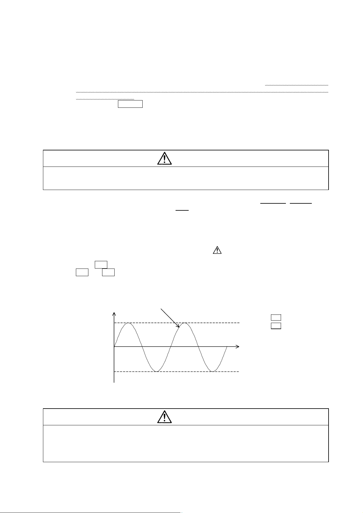
DANGER
WARNING
CAUTION
Precautions for safety
When the operator could be subject to fatalities or serious
injuries if handling is mistaken.
When a dangerous situation, or fatal or serious injuries may
occur if handling is mistaken.
When a dangerous situation may occur if handling is mistaken
leading to medium or minor injuries, or physical damage.
CAUTION
may lead to major results depending on
In this manual, the following items are generically called the "unit".
• Servo drive unit
• Spindle drive unit
• Power supply unit
ii
Page 7
No corresponding items in this manual.
1. Electric shock prevention
Do not open the front cover while the power is ON or during operation. Failure to observe this
could lead to electric shocks.
Do not operate the unit with the front cover removed. The high voltage terminals and charged
sections will be exposed, and can cause electric shocks.
Do not remove the front cover even when the power is OFF unless carrying out wiring work or
periodic inspections. The inside of the units is charged, and can cause electric shocks.
Wait at least 15 minutes after turning the power OFF before starting wiring or inspections.
Failure to observe this could lead to electric shocks.
Always ground the unit and motor following the standards set forth by each country. (In Japan,
grounding resistance 10Ω or less is the standard.)
Wiring and inspection work must be done by a qualified technician.
Wire the servo drive unit and servomotor after installation. Failure to observe this could lead to
electric shocks.
Do not touch the switches with wet hands. Failure to observe this could lead to electric shocks.
Do not damage, apply forcible stress, place heavy items on the cables or get them caught.
Failure to observe this could lead to electric shocks.
DANGER
WARNING
1. Fire prevention
Install the units, motors and regenerative resistor on noncombustible material. Direct installation
on combustible material or near combustible materials could lead to fires.
Shut off the power on the power supply unit side if a fault occurs in the units. Fires could be
caused if a large current continues to flow.
Provide a sequence that shut off the power at the regenerative resistor error signal-ON when
using the regenerative resistor. The regenerative resistor could abnormally overheat and cause
a fire due to a fault in the regenerative transistor, etc.
CAUTION
iii
Page 8
CAUTION
2. Injury prevention
Do not apply a voltage other than that specified in Instruction Manual on each terminal. Failure
to observe this item could lead to ruptures or damage, etc.
Do not mistake the terminal connections. Failure to observe this item could lead to ruptures or
damage, etc.
Do not mistake the polarity (
damage, etc.
Do not touch the radiation fin on unit back face, regenerative resistor or motor, etc., or place
parts (cables, etc.) while the power is turned ON or immediately after turning the power OFF.
These parts may reach high temperatures, and can cause burns.
Structure the cooling fan on the unit back face so that it cannot be touched after installation.
Touching the cooling fan during operation could lead to injuries.
+
,
). Failure to observe this item could lead to ruptures or
3. Various precautions
Observe the following precautions. Incorrect handling of the unit could lead to faults, injuries and
electric shocks, etc.
(1) Transportation and installation
Correctly transport the product according to its weight.
Use the motor's hanging bolts only when transporting the motor. Do not transport the motor
when it is installed on the machine.
Do not stack the products above the tolerable number.
Do not hold the cables, axis or detector when transporting the motor.
Do not hold the connected wires or cables when transporting the units.
Do not hold the front cover when transporting the unit. The unit could drop.
Follow this Instruction Manual and install the unit or motor in a place where the weight can be
borne.
Do not get on top of or place heavy objects on the unit.
Always observe the installation directions of the units or motors.
Secure the specified distance between the units and control panel, or between the servo drive
unit and other devices.
Do not install or run a unit or motor that is damaged or missing parts.
Do not block the intake or exhaust ports of the motor provided with a cooling fan.
Do not let foreign objects enter the units or motors. In particular, if conductive objects such as
screws or metal chips, etc., or combustible materials such as oil enter, rupture or breakage
could occur.
The units and motors are precision devices, so do not drop them or apply strong impacts to
them.
iv
Page 9
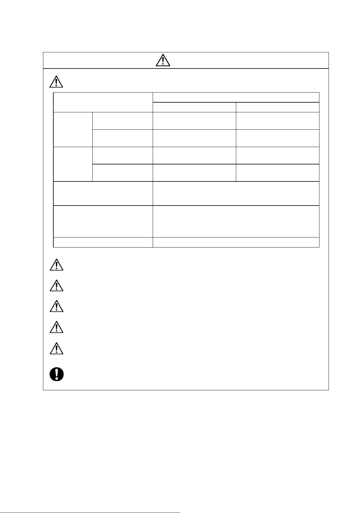
CAUTION
Store and use the units under the following environment conditions.
During operation
Ambient
temperature
During operation
Ambient
humidity
Atmosphere
Altitude
Vibration To follow each unit and motor specifications
Environment
During storage/
transportation
(with no dew condensation)
During storage/
transportation
Securely fix the servomotor to the machine. Insufficient fixing could lead to the servomotor
slipping off during operation.
Always install the servomotor with reduction gear in the designated direction. Failure to do
so could lead to oil leaks.
Structure the rotary sections of the motor so that it can never be touched during operation.
Install a cover, etc., on the shaft.
When installing a coupling to a servomotor shaft end, do not apply an impact by
hammering, etc. The detector could be damaged.
Do not apply a load exceeding the tolerable load onto the servomotor shaft. The shaft
could break.
If the unit has been stored for a long time, always check the operation before starting
actual operation. Please contact the Service Center or Service Station.
(with no dew condensation)
Indoors (where unit is not subject to direct sunlight),
Operation/storage: 1000m or less above sea level
Unit Motor
0°C to 55°C
(with no freezing)
–15°C to 70°C
(with no freezing)
90%RH or less
90%RH or less
with no corrosive gas, combustible gas, oil mist,
dust or conductive particles
Transportation: 10000m or less above sea level
Conditions
0°C to 40°C
(with no freezing)
–15°C to 70°C
(with no freezing)
20% to 90%RH
(with no dew condensation)
90% RH or less
(with no dew condensation)
(Specified value does not apply only
during transport by air.)
v
Page 10
(2) Wiring
Correctly and securely perform the wiring. Failure to do so could lead to runaway of the motor.
Do not install a condensing capacitor, surge absorber or radio noise filter on the output side of
the drive unit.
Correctly connect the output side of the drive unit (terminals U, V, W). Failure to do so could
lead to abnormal operation of the motor.
Always install an AC reactor for each power supply unit.
Always install an appropriate breaker for each power supply unit. The breaker cannot be shared
by several units.
Direct application of a commercial power supply
to the motor could cause burning. Always connect
the motor to the drive unit's output terminals (U,
V, W).
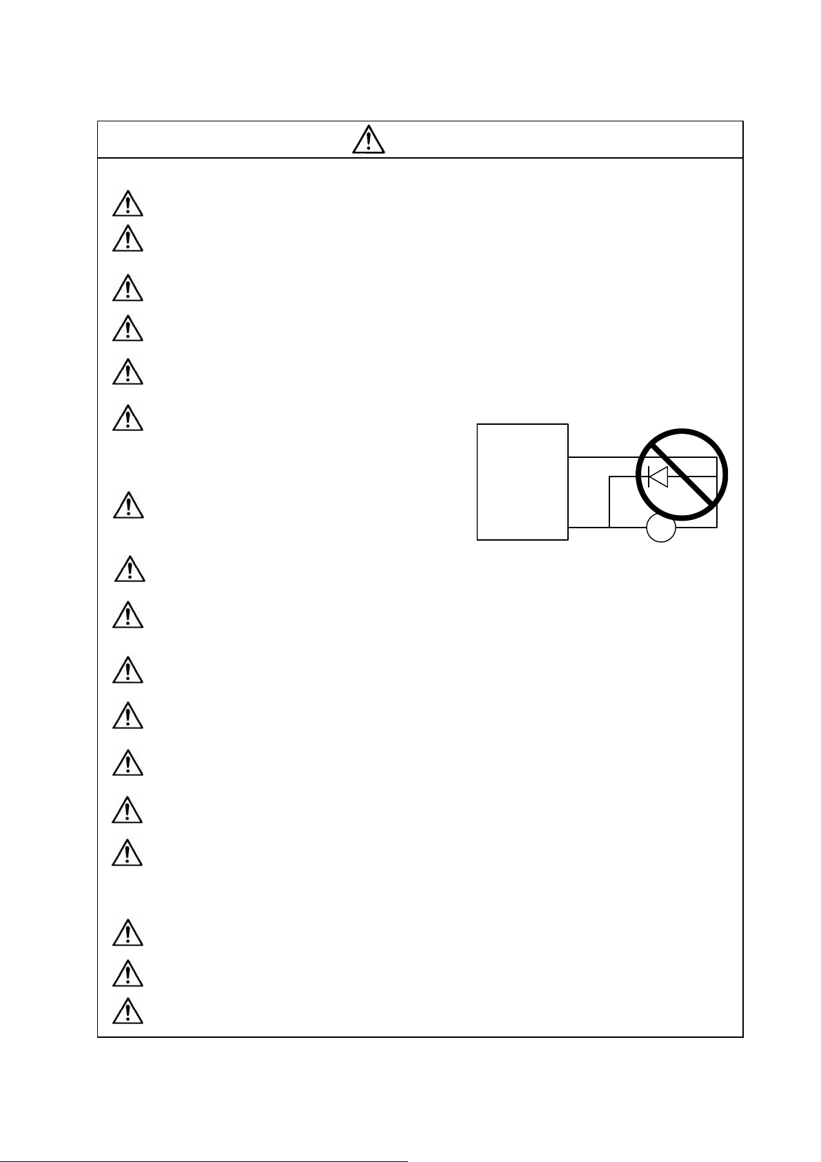
When using an inductive load such as a relay,
always connect a diode as a noise measure
parallel to the load.
When using a capacitance load such as a lamp, always connect a protective resistor as a noise
measure serial to the load.
Do not reverse the direction of a diode which connect to a DC relay for the control output
signals to suppress a surge. Connecting it backwards could cause the drive unit to malfunction
so that signals are not output, and emergency stop and other safety circuits are inoperable.
Do not connect/disconnect the cables connected between the units while the power is ON.
Securely tighten the cable connector fixing screw or fixing mechanism. An insecure fixing could
cause the cable to fall off while the power is ON.
When using a shielded cable instructed in the connection manual, always ground the cable with
a cable clamp, etc.
Always separate the signals wires from the drive wire and power line.
Use wires and cables that have a wire diameter, heat resistance and flexibility that conforms to
the system.
(3) Trial operation and adjustment
CAUTION
Drive unit
COM
(24VDC)
Control output
signal
Diode reverse direction
RA
Check and adjust each program and parameter before starting operation. Failure to do so could
lead to unforeseen operation of the machine.
Do not make remarkable adjustments and changes as the operation could become unstable.
The usable motor and unit combination is predetermined. Always check the models before
starting trial operation.
vi
Page 11
(4) Usage methods
Install an external emergency stop circuit so that the operation can be stopped and power
shut off immediately.
Turn the power OFF immediately if smoke, abnormal noise or odors are generated from the unit
or motor.
Unqualified persons must not disassemble or repair the unit.
Never make modifications.
Reduce magnetic damage by installing a noise filter. The electronic devices used near the unit
could be affected by magnetic noise.
(5) Troubleshooting
Use the unit, motor and regenerative resistor with the designated combination. Failure to do so
could lead to fires or trouble.
The brakes (magnetic brake) assembled into the servomotor are for holding, and must not be
used for normal braking. Do not apply the brakes in the servo ON state. Doing so will lead to a
drop in the brake life. Always turn the servo OFF before applying the brakes.
There may be cases when holding is not possible due to the magnetic brake's life or the
machine construction (when ball screw and servomotor are coupled via a timing belt, etc.).
Install a stop device to ensure safety on the machine side.
After changing the programs/parameters or after maintenance and inspection, always test the
operation before starting actual operation.
Do not enter the movable range of the machine during automatic operation. Never place body
parts near or touch the spindle during rotation.
Follow the power supply specification conditions given in the separate specifications manual for
the power (input voltage, input frequency, tolerable sudden power failure time, etc.).
If a hazardous situation is predicted during power failure or product trouble, use a servomotor
with magnetic brakes or install an external brake mechanism.
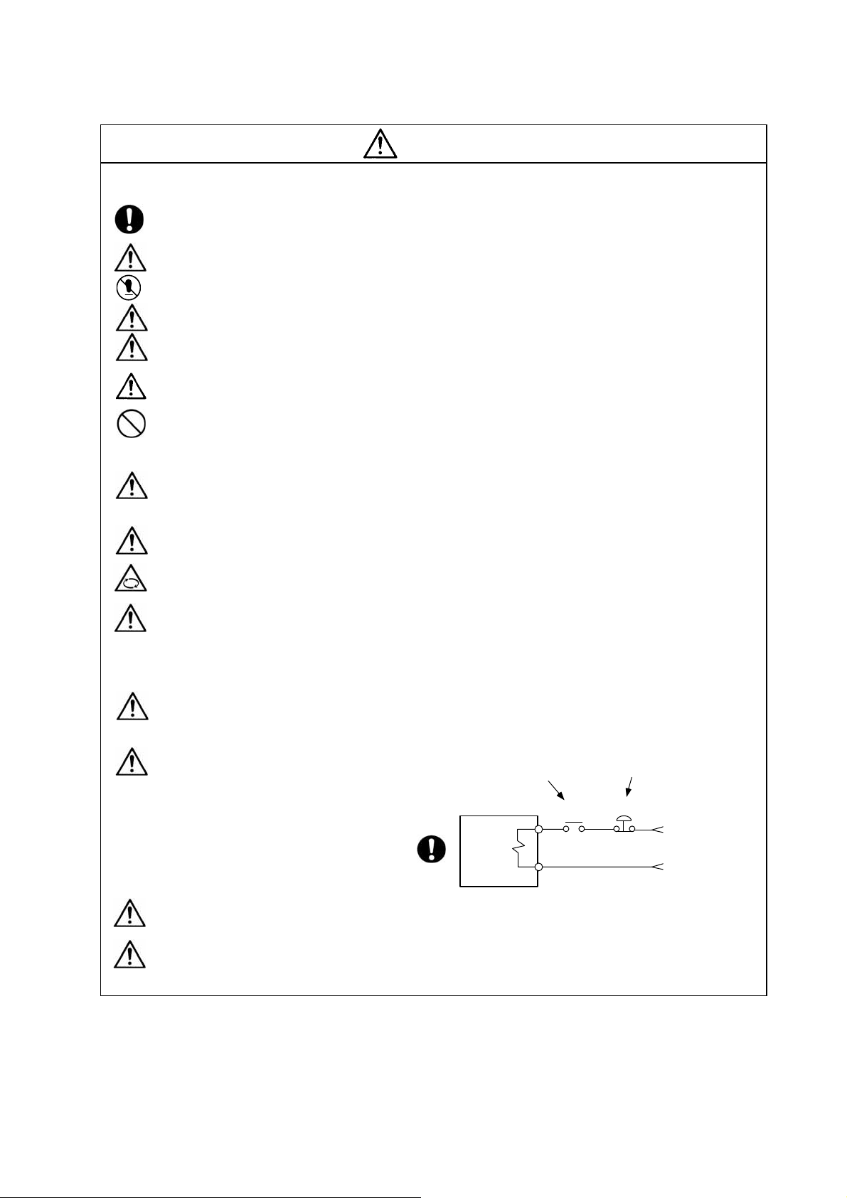
Use a double circuit configuration
that allows the operation circuit for
the magnetic brakes to be operated
even by the external emergency
stop signal.
CAUTION
Shut off with the servomotor
brake control output.
Servomotor
Magnetic
brake
MBR
Shut off with NC brake
control PLC output.
EMG
24VDC
Always turn the input power OFF when an alarm occurs.
Never go near the machine after restoring the power after a power failure, as the machine
could start suddenly. (Design the machine so that personal safety can be ensured even if the
machine starts suddenly.)
vii
Page 12

(6) Maintenance, inspection and part replacement
Always backup the programs and parameters in the CNC device before starting maintenance
or inspections.
The capacity of the electrolytic capacitor will drop over time due to self-discharging, etc. To
prevent secondary disasters due to failures, replacing this part every five years when used
under a normal environment is recommended. Contact the Service Center or Service Station
for replacement.
Do not perform a megger test (insulation resistance measurement) during inspections.
If the battery low warning is issued, back up the machining programs, tool data and
parameters with an input/output unit, and then replace the battery.
Do not short circuit, charge, overheat, incinerate or disassemble the battery.
CFC substitutes are used as refrigerant in the heat dissipating fan in 37kW or smaller
capacity units.
Take care not to damage the heat dissipating fan during maintenance or replacement work.
CAUTION
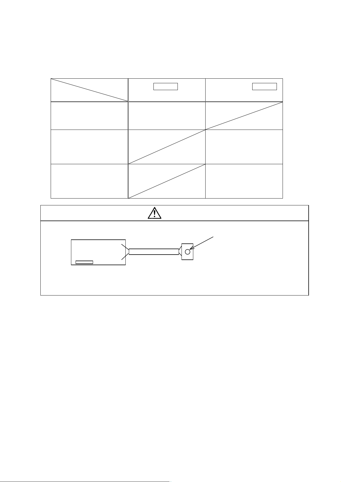
(7) Disposal
Do not treat this unit as general industrial waste. CFC
substitutes are used in the 37kW or smaller capacity units that
have a heat dissipating fan on the back of the unit. Do not
treat this unit as general industrial waste, and always return
the unit to the Service Center or Service Station.
Heat
radiating
fin
Do not disassemble the unit or motor.
Dispose of the battery according to local laws.
(8) General precautions
The drawings given in this Adjustment Procedures show the covers and safety partitions, etc., removed to
provide a clearer explanation. Always return the covers or partitions to their respective places before
starting operation, and always follow the instructions given in this manual.
viii
Page 13

CONTENTS
1. Combinations .................................................................................................................. 1-1
2. PLG PCB check pin and potentiometer positions and functions............................. 2-1
1) PLG No. 1 (With no label on connector)...................................................................... 2-1
2) PLG No. 2 (with green label on connector) ................................................................. 2-1
3) PLG No. 3 (with white label with serial No. stamped on connector) ........................... 2-1
3. Adjustment methods ...................................................................................................... 3-1
1) Adjustment method 1 ................................................................................................... 3-1
2) Adjustment method 2 ................................................................................................... 3-4
3) Adjustment method 3 ................................................................................................... 3-7
4) Z-phase (magnetic) automatic adjustment (Only when using IPM spindle motor) ..... 3-10
5) PLG automatic compensation function........................................................................ 3-10
4. Installing the PLG PCB................................................................................................... 4-1
Page 14

Page 15
(
A
1. Combinations
The adjustment method differs according to the spindle drive unit and PLG PCB combination.
Refer to the following table when adjusting.
Spindle drive
PLG PCB
Does not have label attached
to unit connection connector
protruding from PCB
PLG No. 1)
Has round green label or
square silver label on unit
connection connector
protruding from PCB
(PLG No. 2)
Has square white label with
serial No. stamped on unit
connection connector
protruding from PCB
(PLG No. 3)
unit
Has SAMPLE label
attached to front
Use adjustment method 1
Use adjustment method 2
Use adjustment method 3
Does not have SAMPLE
label attached to front
CAUTION
1. The PLG PCB label is attached at the following position.
Cable
PLG PCB
MP connector
Here
(Round green label,
square silver label, or
square white label)
2. To identify the PLG No. 1 to No. 3, refer to the PCB outline drawings shown in sections 1) to 3) on the
following page. (The outline drawing is correct.)
1 - 1
Page 16
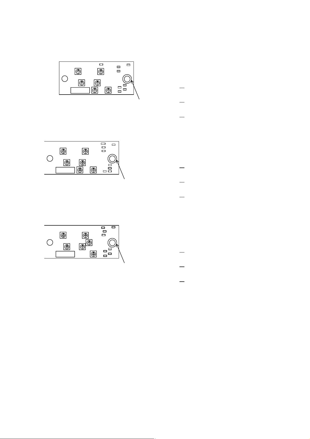
2. PLG PCB check pin and potentiometer positions and functions
1) PLG No. 1 (With no label on connector)
2.5V
VR2
VR4
P6
P5
P0
Check terminal
P0 : Ground (0V)
2.5V : 2.5V signal
VR1
Connector
PCB View of parts
VR3
VR5 VR6
P2
P4
P1
P3
FG
connection
land
P1 : A-phase signal
P2 : A-phase signal
P3 : B-phase signal
P4 : B-phase signal
P5 : Z-phase signal
P6 : Z-phase signal
2) PLG No. 2 (with green label on connector)
2.5V
VR2
VR4
P6
P5
P0
Check terminal
P0 : Ground (0V)
2.5V : 2.5V signal
VR1
Connector
PCB View of parts
VR3
VR5 VR6
P4
P2
P1
P3
FG
connection
land
P1 : A-phase signal
P2 : A-phase signal
P3 : B-phase signal
P4 : B-phase signal
P5 : Z-phase signal
P6 : Z-phase signal
3) PLG No. 3 (with white label with serial No. stamped on connector)
VR6
VR5
VR1
Connector
VR3
PCB View of parts
P6
P25
VR2
VR4
P2
P4
P5
P0
P1
P3
FG
connection
land
Check terminal
P0 : Ground (0V)
2.5V : 2.5V signal
P1 : A-phase signal
P2 : A-phase signal
P3 : B-phase signal
P4 : B-phase signal
P5 : Z-phase signal
P6 : Z-phase signal
Potentiometer
VR1: A-phase 0 position
VR2: A-phase gain adjustment
VR3: B-phase 0 position
VR4: B-phase gain adjustment
VR5: Z-phase 0 position
VR6: Z-phase gain
Potentiometer
VR1: A-phase 0 position
VR2: A-phase gain adjustment
VR3: B-phase 0 position
VR4: B-phase gain adjustment
VR5: Z-phase 0 position
VR6: Z-phase gain
Potentiometer
VR1: A-phase 0 position
VR2: A-phase gain adjustment
VR3: B-phase 0 position
VR4: B-phase gain adjustment
VR5: Z-phase 0 position
VR6: Z-phase gain
adjustment
adjustment
adjustment
adjustment
adjustment
adjustment
adjustment
adjustment
adjustment
adjustment
adjustment
adjustment
2 - 1
Page 17
A
3. Adjustment methods
1) Adjustment method 1 (PLG No. 1)
(1) Set the spindle parameter SP038 (SFNC6) bit F to "1", and turn the NC and spindle drive unit
power OFF. (Enter the open loop state (detector signal invalid mode). However, in the case of
IPM spindle motor, as open loop is not possible, rotate the motor at low speed externally to
check the waveform.)
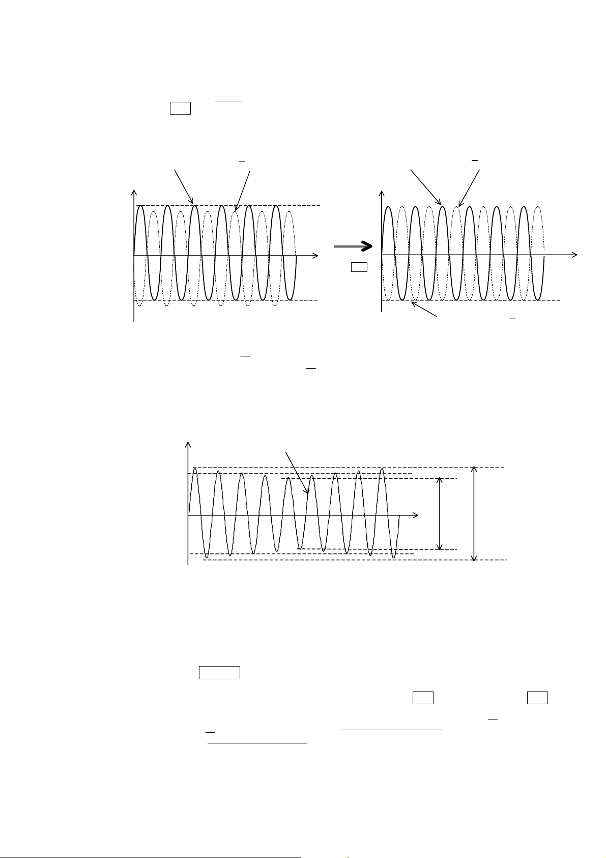
(2) First adjust the A-phase. Prepare two synchroscopes and probes. Connect the ground of the
probe connected to the synchroscope's CH1 to the 2.5V terminal on the PLG PCB, and signal
side to the P1 terminal. In the same manner, connect the ground of the probe connected to
CH2 to the 2.5V terminal and the signal side to the P2 terminal.
(Bundle the CH1 and CH2 ground wires connected to the 2.5V terminal with a clip and connect
to the 2.5V terminal.)
CAUTION
If the synchroscope's power cable is provided with a grounding terminal, do not connect this
section to the ground. Make sure that the synchroscope does not contact the machine or other
ground section when adjusting the waveform.
(3) Next, set the synchroscope's CH1 and CH2 measurement range to 20mV/div (0.2V/div when
using 1:1 probe). Set the time axis to 50µs, and CH1 and CH2 to the DC range. First, using the
synchroscope's button (switch) as the GND, adjust CH1 and CH2 with the synchroscope's 0V
adjustment dial so that the center of each screen comes to 0V.
Then, release the GND only for CH1 so that the normal DC voltage waveform for CH1 can be
measured.
(4) Turn the spindle drive unit and NC power ON, input a forward run command, and rotate the
motor at the reference rotation speed (refer to "
rotation speed is not the spindle rotation speed.)
(5) Adjust VR1 so that the CH1 waveform's DC element comes approximately to 0V. Then adjust
VR2 and VR1 so that the peak value (waveform width) is 1.1V (±0.08V)
0V is 0.55V (±0.04V).
(Refer to Fig. 1)
CAUTION"). (Note that the reference
and one side from
P-P
Voltage (V)
0.51 to 0.59
0
–0.51 to –0.59
-phase (P1 terminal)
Offset : VR1
Gain : VR2
Time
Fig. 1 A-phase waveform during motor forward run
(When looking at A-phase from 2.5V terminal)
CAUTION
The motor's reference rotation speed is calculated with the following expression.
Reference rotation speed (r/min) = 1800 (r/min) × (256/No. of PLG gear teeth in use)
Example: When No. of PLG teeth is 128p/rev 1800 × 256/128 = 3600r/min
In the open loop state, the reference rotation speed may not be attained unless the motor speed is raised
gradually (100 to 500r/min).
3 - 1
Page 18
A
A
A
A
A
A
A
A
(6) Next, release the GND for CH2 so that CH2 can be observed simultaneously with CH1, and set
the time axis to the 200µs
range.
(7) Readjust VR1 so that the minimum value of the synchroscope's waveform is constant (±0.02V
or less) for both waveforms.
(Refer to Fig. 2)
0.51 to 0.59
–0.51 to –0.59
After finishing the adjustment up to this point, confirm that the A-phase waveform's envelope
Voltage (V)
0
-phas e (P1 te rminal)
-phas e (P2 te rminal)
Voltage (V)
Time
djust VR1
-phase (P1 terminal)
0
Set the bottom side of the wavefor m
for the A-phase and A-phase to
approx. the same value.
(Difference: ±0.02V or less)
Fig. 2 A-phase, A-phase waveform during motor forward run
(When looking at A-phase, A-phase from 2.5V terminal)
(maximum amplitude α – minimum amplitude β) is 0.2V or less. (Refer to Fig. 3)
Voltage (V)
-phase (P1 terminal)
-phase (P2 terminal)
Time
pprox. 0.55
Time
0
pprox. –0.55
β
Minimum amplitude
α
Maximum amplitude
Fig. 3 A-phase waveform during motor forward run
(When looking at A-phase from 2.5V terminal)
Envelope = maximum amplitude α – minimum amplitude β)
(8) When completed with the adjustment, stop the motor, and turn the NC and spindle drive unit
power OFF.
(9) Next, adjust the B-phase. Connect the synchroscope's CH1 to the PLG PCB's P3 terminal and
CH2 to the P4 terminal.
(10) Carry out steps (3) to (8) (same as A-phase adjustment). Adjust VR4 instead of VR2, and VR3
instead of VR1. Refer to the waveforms for adjusting the A-phase. When viewing the figures,
substitute the A-phase (P1 terminal) with the B-phase (P3 terminal)
terminal) with the B-phase (P4 terminal)
, and adjust.
, and the A-phase (P2
3 - 2
Page 19

(11) Next, adjust the Z-phase. Connect the synchroscope's CH1 to the PLG PCB's P5 terminal
and
CH2 to the P6 terminal.
(12) Using step (3), adjust 0V using the voltage range 20mV. Set CH1 to the DC range, CH2 to
GND, and the time axis to 50µs
. Adjust VR5 so that the sections other than the waveform's
crest are approx. –0.15V, and then adjust VR6 so that the peak value of the crest looking from
a section other than the waveform crest is 0.7V to 0.85V. After this, adjust VR5 again so that
the sections other than the waveform's crest are between –0.15V and –0.2V. Finally, cancel
the CH2 GND, and confirm that the section other than the crest in the CH2 waveform are 0.1V
or more.
(Refer to Fig. 4)
Voltage (V)
Offset : VR5
Gain : VR6
(0.5 to 0.6)
–0.2 to –0.25
0.1 or more
0.7 to 0.85
Z-phase (P6 terminal)
0
Z-phase (P5 terminal)
Time
Fig. 4 Z-phase, Z-phase waveform during motor forward run
(When looking at Z-phase, Z-phase from 2.5V terminal)
(13) This completes adjustment of the potentiometer on the PLG PCB.
(14) When finished adjusting the potentiometer, stop the motor, and return the SP038 (SFNC6) bit
F setting to "0". Then, turn the NC and spindle drive unit power OFF.
(15) Turn the NC and spindle drive unit power ON again, and carry out section "3.4) PLG automatic
compensation function". This completes the adjustment. When finished, refer to section "4.
Installing the PLG PCB", and correctly install the PCB.
CAUTION
1. When confirming the waveform in the normal operation state (closed loop), disconnect the PLG cable
from the drive unit, and insert a check pin card between CN5 and the PLG cable. The check pin
numbers corresponding to each signal in this case are shown below. Note that each signal has a
+2.5V offset. Always remove the check pin card after confirming the waveform.
If the waveform is checked with the PLG PCB's check terminal in the closed loop state without using
the check pin card, abnormal noise or vibration may be generated from the motor.
A-phase signal: CH6 B-phase signal: CH7 Z-phase signal: CH18
A-phase signal: CH16 B-phase signal: CH17 Z-phase signal: CH8
2. After adjusting the potentiometer, always fix with lock paint, etc., so that the position does
not deviate.
3 - 3
Page 20

A
2) Adjustment method 2 (PLG No. 2)
(1) Set the spindle parameter SP038 (SFNC6) bit F to "1", and turn the NC and spindle drive unit
power OFF. (Enter the open loop state. However, in the case of IPM spindle motor, as open
loop is not possible, rotate the motor at low speed externally to check the waveform.)
(2) First adjust the A-phase. Prepare two synchroscopes and probes. Connect the ground of the
probe connected to the synchroscope's CH1 to the 2.5V terminal on the PLG PCB, and signal
side to the P1 terminal. In the same manner, connect the ground of the probe connected to
CH2 to the 2.5V terminal and the signal side to the P2 terminal.
(Bundle the CH1 and CH2 ground wires connected to the 2.5V terminal with a clip and connect
to the 2.5V terminal.)
CAUTION
If the synchroscope's power cable is provided with a grounding terminal, do not connect this
section to the ground. Make sure that the synchroscope does not contact the machine or other
ground section when adjusting the waveform.
(3) Next, set the synchroscope's CH1 and CH2 measurement range to 10mV/div (0.1V/div when
using 1:1 probe). Set the time axis to 50µs, and CH1 and CH2 to the DC range. First, using the
synchroscope's button (switch) as the GND, adjust CH1 and CH2 with the synchroscope's 0V
adjustment dial so that the center of each screen comes to 0V.
Then, release the GND only for CH1 so that the normal DC voltage waveform for CH1 can be
measured.
(4) Turn the spindle drive unit and NC power ON, input a forward run command, and rotate the
motor at the reference rotation speed (refer to "
CAUTION"). (Note that the reference
rotation speed is not the spindle rotation speed.)
(5) Adjust VR1 so that the CH1 waveform's DC element comes approximately to 0V. Then adjust
VR2 and VR1 so that the peak value (waveform width) is 0.5V (±0.02V)
and one side from
P-P
0V is 0.25V (±0.01V).
(Refer to Fig. 1)
Voltage (V)
0.24 to 0.26
0
–0.24 to –0.26
-phase (P1 terminal)
Offset : VR1
Gain : VR2
Time
Fig. 5 A-phase waveform during motor forward run
(When looking at A-phase from 2.5V terminal)
CAUTION
The motor's reference rotation speed is calculated with the following expression.
Reference rotation speed (r/min) = 1800 (r/min) × (256/No. of PLG gear teeth in use)
Example: When No. of PLG teeth is 128p/rev 1800 × 256/128 = 3600r/min
In the open loop state, the reference rotation speed may not be attained unless the motor speed is raised
gradually (100 to 500r/min).
3 - 4
Page 21

A
A
A
A
A
A
A
A
(6) Next, release the GND for CH2 so that CH2 can be observed simultaneously with CH1, and set
the time axis to the 200µs
range.
(7) Readjust VR1 so that the minimum value of the synchroscope's waveform is constant (±0.01V
or less) for both waveforms.
(Refer to Fig. 6)
0.24 to 0.26
–0.24 to –0.26
After finishing the adjustment up to this point, confirm that the A-phase waveform's envelope
Voltage (V)
0
-phas e (P1 te rminal)
-phas e (P2 te rminal)
Voltage (V)
Time
djust VR1
-phase (P1 terminal)
0
Set the bottom side of the wavefor m
for the A-phase and A-phase to
approx. the same value.
(Difference: ±0.01V or less)
Fig. 6 A-phase, A-phase waveform during motor forward run
(When looking at A-phase, A-phase from 2.5V terminal)
(maximum amplitude α – minimum amplitude β) is 0.03V or less. (Refer to Fig. 7)
Voltage (V)
-phase (P1 terminal)
-phase (P2 terminal)
Time
pprox. 0.25
Time
0
pprox. –0.25
β
Minimum amplitude
α
Maximum amplitude
Fig. 7 A-phase waveform during motor forward run
(When looking at A-phase from 2.5V terminal)
Envelope = maximum amplitude α – minimum amplitude β)
(8) When completed with the adjustment, stop the motor, and turn the NC and spindle drive unit
power OFF.
(9) Next, adjust the B-phase. Connect the synchroscope's CH1 to the PLG PCB's P3 terminal and
CH2 to the P4 terminal.
(10) Carry out steps (3) to (8) (same as A-phase adjustment). Adjust VR4 instead of VR2, and VR3
instead of VR1. Refer to the waveforms for adjusting the A-phase. When viewing the figures,
substitute the A-phase (P1 terminal) with the B-phase (P3 terminal)
terminal) with the B-phase (P4 terminal)
, and adjust.
, and the A-phase (P2
3 - 5
Page 22

(11) Next, adjust the Z-phase. Connect the synchroscope's CH1 to the PLG PCB's P5 terminal
and
CH2 to the P6 terminal.
(12) Using step (3), adjust 0V. Set CH1 to the DC range, CH2 to GND, and the time axis to 50µs.
Adjust VR5 so that the sections other than the waveform's crest are approx. –0.1V, and then
adjust VR6 so that the peak value of the crest looking from a section other than the waveform
crest is 0.4V to 0.5V. After this, adjust VR5 again so that the sections other than the
waveform's crest are between –0.1V and –0.15V. Finally, cancel the CH2 GND, and confirm
that the section other than the crest in the CH2 waveform are 0V or more. (Refer to Fig. 8)
Voltage (V)
Offset : VR5
Gain : VR6
(0.25 to 0.4)
–0.1 to –0.15
0.1 or more
0.4 to 0.5V
Z-phase (P6 terminal)
0
Z-phase (P5 terminal)
Time
Fig. 8 Z-phase, Z-phase waveform during motor forward run
(When looking at Z-phase, Z-phase from 2.5V terminal)
(13) This completes adjustment of the potentiometer on the PLG PCB.
(14) When finished adjusting the potentiometer, stop the motor, and return the SP038 (SFNC6) bit
F setting to "0". Then, turn the NC and spindle drive unit power OFF.
(15) Turn the NC and spindle drive unit power ON again, and carry out section "3.4) PLG automatic
compensation function". This completes the adjustment. When finished, refer to section "4.
Installing the PLG PCB", and correctly install the PCB.
CAUTION
1. When confirming the waveform in the normal operation state (closed loop), disconnect the PLG cable
from the drive unit, and insert a check pin card between CN5 and the PLG cable. The check pin
numbers corresponding to each signal in this case are shown below. Note that each signal has a
+2.5V offset. Always remove the check pin card after confirming the waveform.
If the waveform is checked with the PLG PCB's check terminal in the closed loop state without using
the check pin card, abnormal noise or vibration may be generated from the motor.
A-phase signal: CH6 B-phase signal: CH7 Z-phase signal: CH18
A-phase signal: CH16 B-phase signal: CH17 Z-phase signal: CH8
2. After adjusting the potentiometer, always fix with lock paint, etc., so that the position does
not deviate.
3 - 6
Page 23

A
3) Adjustment method 3 (PLG No. 3)
(1) Set the spindle parameter SP038 (SFNC6) bit F to "1", and turn the NC and spindle drive unit
power OFF. (Enter the open loop state. However, in the case of IPM spindle motor, as open
loop is not possible, rotate the motor at low speed externally to check the waveform.)
(2) First adjust the A-phase. Prepare two synchroscopes and probes. Connect the ground of the
probe connected to the synchroscope's CH1 to the P25 terminal on the PLG PCB, and signal
side to the P1 terminal. In the same manner, connect the ground of the probe connected to
CH2 to the P25 terminal and the signal side to the P2 terminal.
(Bundle the CH1 and CH2 ground wires connected to the P25 terminal with a clip and connect
to the P25 terminal.)
CAUTION
If the synchroscope's power cable is provided with a grounding terminal, do not connect this
section to the ground. Make sure that the synchroscope does not contact the machine or other
ground section when adjusting the waveform.
(3) Next, set the synchroscope's CH1 and CH2 measurement range to 10mV/div (0.1V/div when
using 1:1 probe). Set the time axis to 50µs, and CH1 and CH2 to the DC range. First, using the
synchroscope's button (switch) as the GND, adjust CH1 and CH2 with the synchroscope's 0V
adjustment dial so that the center of each screen comes to 0V.
Then, release the GND only for CH1 so that the normal DC voltage waveform for CH1 can be
measured.
(4) Turn the spindle drive unit and NC power ON, input a forward run command, and rotate the
motor at the reference rotation speed (refer to "
CAUTION"). (Note that the reference
rotation speed is not the spindle rotation speed.)
(5) Adjust VR1 so that the CH1 waveform's DC element comes approximately to 0V. Then adjust
VR2 and VR1 so that the peak value (waveform width) is 0.54V (±0.02V)
and one side from
P-P
0V is 0.27V (±0.01V).
(Refer to Fig. 9)
Voltage (V)
0.26 to 0.28
0
–0.26 to –0.28
-phase (P1 terminal)
Offset : VR1
Gain : VR2
Time
Fig. 9 A-phase waveform during motor forward run
(When looking at A-phase from P25 terminal)
CAUTION
The motor's reference rotation speed is calculated with the following expression.
Reference rotation speed (r/min) = 1800 (r/min) × (256/No. of PLG gear teeth in use)
Example: When No. of PLG teeth is 128p/rev 1800 × 256/128 = 3600r/min
In the open loop state, the reference rotation speed may not be attained unless the motor speed is raised
gradually (100 to 500r/min).
3 - 7
Page 24

A
A
A
A
A
A
A
A
(6) Next, release the GND for CH2 so that CH2 can be observed simultaneously with CH1, and set
the time axis to the 200µs
range.
(7) Readjust VR1 so that the minimum value of the synchroscope's waveform is constant (±0.01V
or less) for both waveforms.
(Refer to Fig. 10)
0.26 to 0.28
–0.26 to –0.28
After finishing the adjustment up to this point, confirm that the A-phase waveform's envelope
Voltage (V)
0
-phas e (P1 te rminal)
-phas e (P2 te rminal)
Voltage (V)
Time
djust VR1
-phase (P1 terminal)
0
Set the bottom side of the wavefor m
for the A-phase and A-phase to
approx. the same value.
(Difference: ±0.01V or less)
Fig. 10 A-phase, A-phase waveform during motor forward run
(When looking at A-phase, A-phase from P25 terminal)
(maximum amplitude α – minimum amplitude β) is 0.03V or less. (Refer to Fig. 11)
Voltage (V)
-phase (P1 terminal)
-phase (P2 terminal)
Time
pprox. 0.27
Time
0
pprox. –0.27
β
Minimum amplitude
α
Maximum amplitude
Fig. 11 A-phase waveform during motor forward run
(When looking at A-phase from P25 terminal)
Envelope = maximum amplitude α – minimum amplitude β)
(8) When completed with the adjustment, stop the motor, and turn the NC and spindle drive unit
power OFF.
(9) Next, adjust the B-phase. Connect the synchroscope's CH1 to the PLG PCB's P3 terminal and
CH2 to the P4 terminal.
(10) Carry out steps (3) to (8) (same as A-phase adjustment). Adjust VR4 instead of VR2, and VR3
instead of VR1. Refer to the waveforms for adjusting the A-phase. When viewing the figures,
substitute the A-phase (P1 terminal) with the B-phase (P3 terminal)
terminal) with the B-phase (P4 terminal)
, and adjust.
, and the A-phase (P2
3 - 8
Page 25

(11) Next, adjust the Z-phase. Connect the synchroscope's CH1 to the PLG PCB's P5 terminal
and
CH2 to the P6 terminal.
(12) Using step (3), adjust 0V. Set CH1 to the DC range, CH2 to GND, and the time axis to 50µs.
Adjust VR5 so that the sections other than the waveform's crest are approx. –0.1V, and then
adjust VR6 so that the peak value of the crest looking from a section other than the waveform
crest is 0.4V to 0.5V. After this, adjust VR5 again so that the sections other than the
waveform's crest are between –0.1V and –0.15V. Finally, cancel the CH2 GND, and confirm
that the section other than the crest in the CH2 waveform are 0V or more. (Refer to Fig. 12)
Voltage (V)
Offset : VR5
Gain : VR6
(0.25 to 0.4)
–0.1 to –0.15
0.1 or more
0.4 to 0.5V
Z-phase (P6 terminal)
0
Z-phase (P5 terminal)
Time
Fig. 12 Z-phase, Z-phase waveform during motor forward run
(When looking at Z-phase, Z-phase from P25 terminal)
(13) This completes adjustment of the potentiometer on the PLG PCB.
(14) When finished adjusting the potentiometer, stop the motor, and return the SP038 (SFNC6) bit
F setting to "0". Then, turn the NC and spindle drive unit power OFF.
(15) Turn the NC and spindle drive unit power ON again, and carry out section "3.4) PLG automatic
compensation function". This completes the adjustment. When finished, refer to section "4.
Installing the PLG PCB", and correctly install the PCB.
CAUTION
1. When confirming the waveform in the normal operation state (closed loop), disconnect the PLG cable
from the amplifier, and insert a check pin card between CN5 and the PLG cable. The check pin
numbers corresponding to each signal in this case are shown below. Note that each signal has a
+2.5V offset. Always remove the check pin card after confirming the waveform.
If the waveform is checked with the PLG PCB's check terminal in the closed loop state without using
the check pin card, abnormal noise or vibration may be generated from the motor.
A-phase signal: CH6 B-phase signal: CH7 Z-phase signal: CH18
A-phase signal: CH16 B-phase signal: CH17 Z-phase signal: CH8
2. After adjusting the potentiometer, always fix with lock paint, etc., so that the position does
not deviate.
3 - 9
Page 26

4) Z-phase (magnetic) automatic adjustment (Only when using IPM spindle motor)
Z-phase automatic adjustment is a function that automatically adjusts the relative position of the motor
magnetic pole and the PLG Z-phase pulse signal input into the spindle drive unit, and then saves and
validates the adjustment data.
This function is used to increase the output torque accuracy, and must always be carried out when the
machine is started. Execute this function with the following procedures.
CAUTION
1. The mechanical adjustments (gear - sensor gap, etc.) must already be completed.
2. When using this function, set the spindle load GD2 (max.: approx. 5-fold of the motor GD2) and the
frictional load as low as possible.
3. The motor will automatically rotate at the adjustment speed during the Z-phase automatic
adjustment. Do not touch the rotating sections, as these are hazardous.
4. If START (ON) is executed before the adjustment is completed, alarm 16 will occur, and the
protection function will activate.
(1) Change SP205 from 0 to 1, and start forward run operation. (The power does not need to be
turned OFF and ON.)
The control output 4H bit "D" will be set to 1 until the unit power is turned ON again.
1) The spindle motor will automatically rotate at the adjustment speed (two steps for Z-phase
pulse detection and magnetic pole position detection).
2) The adjustment results will be calculated approximately 90 seconds after forward run is
started (this time will differ slightly according to the magnetic pole position). Then operation
will stop automatically.
(2) Confirm that the motor has automatically stopped. Leave parameter SP205 set to 1, turn START
OFF, and turn the power OFF and ON. (When SP205 is set to 1, the adjustment data saved in
SPm will be used.)
1) If START is turned OFF during automatic rotation, reset SP205 to 0, and turn the power OFF
and ON. Then, repeat the procedure from step (1).
2) If the drive unit or motor is replaced, if the PLG is reinstalled, or if the signals are readjusted,
etc., always reset SP205 to 0, and turn the power OFF and ON. Then, repeat the procedure
from step
(1). Failure to observe this will prevent correct operation due to invalid adjustment data.
5) PLG automatic compensation function
(1) Turn the NC and spindle drive unit power ON, and change the spindle parameter SP245
(PGHS) setting from "0" to "1". (If already set to "1", reset it to "0" and then to "1" again with the
power ON.)
(2) Input the forward run command or reverse run command. The motor will rotate in the forward
direction when the command is input, and automatic compensation will be executed. (The
motor will rotate at a maximum of 1500r/min regardless of the speed command's size, and will
stop in several seconds.)
WARNING
When the forward run or reverse run command is input, the motor will rotate at a high speed
regardless of the speed command's size. Do not touch or approach the motor or spindle during
this time. Failure to observe this could result in personal injury.
(3) After the motor stops, turn the forward run (or reverse run) signal OFF. Turn the NC power OFF
and then turn the spindle drive unit power OFF.
This completes PLG automatic compensation. (Leave SP245 set to "1".)
3 - 10
Page 27

CAUTION
1. When the motor stops after PLG automatic compensation is completed, always turn the forward run
(or reverse run) command OFF.
2. If the spindle parameter SP245 is returned to "0", the PLG automatic compensation will be invalidated
regardless of whether the NC power is turned ON or OFF. If the setting is changed to "0" by mistake,
start again from step (1).
3. Even if the PLG automatic compensation has been completed for the spindle drive unit or motor, this
adjustment must be made again when the spindle drive unit, motor, NC or card is replaced.
3 - 11
Page 28

4. Installing the PLG PCB
Correctly install the PLG PCB after finishing the adjustments.
Do not insert the white insulation washer, and instead just tighten the installation screw.
Always use a metal stud on the side fixing the PLG PCB's FG connection ground, and connect
to the ground. If this stud is not metal, or if it is metal but not connected to the ground, connect
the separate grounding wire to the FG connection land on the PLG PCB (tighten together).
Installation screw
Cover
PLC PCB
Insulation washer
(do not insert)
Stud
4 - 1
Page 29

Page 30

Revision history
Sub No.
Date of revi sion Revision details
G July 2002
H Feb 2004
• Newly issued
• Added the note in using an IPM spindle motor.
The note is added to (1) of 1) to 2) of 3.
Added 4) Z phase automatic adjustment.
Page 31

Notice
Every effort has been made to keep up with software and hardware revisions in the
contents described in this manual. However, please understand that in some
unavoidable cases simultaneous revision is not possible.
Please contact your Mitsubishi Electric dealer with any questions or comments
regarding the use of this product.
Duplication Prohibited
This instruction manual may not be reproduced in any form, in part or in whole,
without written permission from Mitsubishi Electric Corporation.
©
ALL RIGHTS RESERVED
2001 MITSUBISHI ELECTRIC CORPORATION
Page 32

MITSUBISHI ELECTRIC CORPORATION
HEAD OFFICE: MITSUBISHI DENKI BLDG. MARUNOUCHI. TOKYO 100 TEL:03-3218-3426
 Loading...