

Page 1

Page 2

MELDAS is a registered trademark of Mitsubishi Electric Corporation.
Other company and product names that appear in this manual are trademarks or registered
trademarks of their respective companies.
Page 3

Introduction
Thank you for selecting the Mitsubishi numerical control unit.
This instruction manual describes the handling and caution points for using this AC
servo/spindle.
Incorrect handling may lead to unforeseen accidents, so always read this instruction
manual thoroughly to ensure correct usage.
Make sure that this instruction manual is delivered to the end user.
Always store this manual in a safe place.
All specifications for the MDS-CH Series are described in this manual. However, each
CNC may not be provided with all specifications, so refer to the specifications for the
CNC on hand before starting use.
Notes on Reading This Manual
(1) Since the description of this specification manual deals with NC in general, for the
specifications of individual machine tools, refer to the manuals issued by the
respective machine manufacturers. The "restrictions" and "available functions"
described in the manuals issued by the machine manufacturers have precedence
to those in this manual.
(2) This manual describes as many special operations as possible, but it should be
kept in mind that items not mentioned in this manual cannot be performed.
Page 4
Precautions for safety
Please read this manual and auxiliary documents before starting installation, operation,
maintenance or inspection to ensure correct usage. Thoroughly understand the device, safety
information and precautions before starting operation.
The safety precautions in this instruction manual are ranked as "WARNING" and "CAUTION".
Note that some items described as
the situation. In any case, important information that must be observed is described.
The numeric control unit is configured of the control unit, operation board, servo drive unit,
spindle drive unit, power supply, servomotor and spindle motor, etc.
In this manual, the following items are generically called the "motor".
• Servomotor
• Linear servomotor
• Spindle motor
DANGER
WARNING
CAUTION
When there is a potential risk of fatal or serious injuries if
handling is mistaken.
When a dangerous situation, or fatal or serious injuries may
occur if handling is mistaken.
When a dangerous situation may occur if handling is mistaken
leading to medium or minor injuries, or physical damage.
CAUTION
may lead to major results depending on
In this manual, the following items are generically called the "unit".
• Servo drive unit
• Spindle drive unit
• Power supply unit
• Scale I/F unit
• Magnetic pole detection unit
Page 5
There are no "DANGER" items in this manual.
1. Electric shock prevention
Do not open the front cover while the power is ON or during operation. Failure to observe this
could lead to electric shocks.
Do not operate the unit with the front cover removed. The high voltage terminals and charged
sections will be exposed, and can cause electric shocks.
Do not remove the front cover even when the power is OFF unless carrying out wiring work or
periodic inspections. The inside of the units is charged, and can cause electric shocks.
Wait at least 15 minutes after turning the power OFF before starting wiring or inspections.
Failure to observe this could lead to electric shocks.
Ground the unit and motor with Class C (former class 3) grounding or higher.
Wiring and inspection work must be done by a qualified technician.
Wire the servo drive unit and servomotor after installation. Failure to observe this could lead to
electric shocks.
Do not touch the switches with wet hands. Failure to observe this could lead to electric shocks.
Do not damage, apply forcible stress, place heavy items on the cables or get them caught.
Failure to observe this could lead to electric shocks.
DANGER
WARNING
2. Injury prevention
The linear servomotor uses a powerful magnet on the secondary side, and could adversely
affect pacemakers, etc.
During installation and operation of the machine, do not place portable items that could
malfunction or fail due to the influence of the linear servomotor's magnetic force.
Take special care not to pinch fingers, etc., when installing (and unpacking) the linear
servomotor.
1. Fire prevention
Install the units, motors and regenerative resistor on noncombustible material. Direct installation
on combustible material or near combustible materials could lead to fires.
Shut off the power on the power supply unit side if a fault occurs in the units. Fires could be
caused if a large current continues to flow.
Provide a sequence that shut off the power at the regenerative resistor error signal-ON when
using the regenerative resistor. The regenerative resistor could abnormally overheat and cause
a fire due to a fault in the regenerative transistor, etc.
The battery unit could heat up, ignite or rupture if submerged in water, or if the poles are
incorrectly wired.
CAUTION
Page 6
CAUTION
2. Injury prevention
Do not apply a voltage other than that specified in Instruction Manual on each terminal. Failure
to observe this item could lead to ruptures or damage, etc.
Do not mistake the terminal connections. Failure to observe this item could lead to ruptures or
damage, etc.
Do not mistake the polarity (
damage, etc.
Do not touch the radiation fin on unit back face, regenerative resistor or motor, etc., or place
parts (cables, etc.) while the power is turned ON or immediately after turning the power OFF.
These parts may reach high temperatures, and can cause burns.
Structure the cooling fan on the unit back face so that it cannot be touched after installation.
Touching the cooling fan during operation could lead to injuries.
+
,
). Failure to observe this item could lead to ruptures or
3. Various precautions
Observe the following precautions. Incorrect handling of the unit could lead to faults, injuries and
electric shocks, etc.
(1) Transportation and installation
Correctly transport the product according to its weight.
Use the motor's hanging bolts only when transporting the motor. Do not transport the motor
when it is installed on the machine.
Do not stack the products above the tolerable number.
Do not hold the cables, axis or detector when transporting the motor.
Do not hold the connected wires or cables when transporting the units.
Do not hold the front cover when transporting the unit. The unit could drop.
Follow this Instruction Manual and install the unit or motor in a place where the weight can be
borne.
Do not get on top of or place heavy objects on the unit.
Always observe the installation directions of the units or motors.
Secure the specified distance between the units and control panel, or between the servo drive
unit and other devices.
Do not install or run a unit or motor that is damaged or missing parts.
Do not block the intake or exhaust ports of the motor provided with a cooling fan.
Do not let foreign objects enter the units or motors. In particular, if conductive objects such as
screws or metal chips, etc., or combustible materials such as oil enter, rupture or breakage
could occur.
The units and motors are precision devices, so do not drop them or apply strong impacts to
them.
Page 7
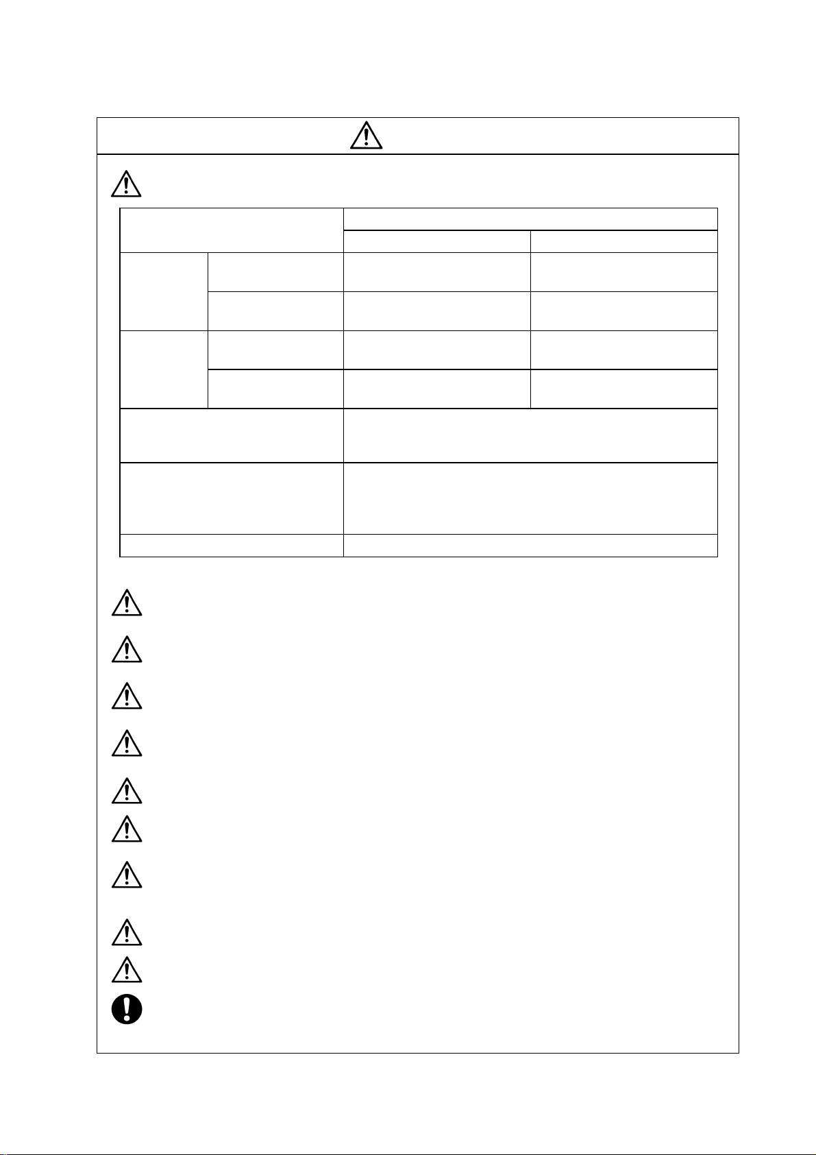
CAUTION
Store and use the units under the following environment conditions.
During operation
Ambient
temperature
During operation
Ambient
humidity
Atmosphere
Altitude
Vibrat ion To follow each unit and motor specifications
Note 1) -15°C to 55°C for linear servomotor.
Environment
During storage/
transportation
(with no dew condensation)
During storage/
transportation
Securely fix the servomotor to the machine. Insufficient fixing could lead to the servomotor
slipping off during operation.
Always install the servomotor with reduction gear in the designated direction. Failure to do
so could lead to oil leaks.
Structure the rotary sections of the motor so that it can never be touched during operation.
Install a cover, etc., on the shaft.
When installing a coupling to a servomotor shaft end, do not apply an impact by
hammering, etc. The detector could be damaged.
Do not apply a load exceeding the tolerable load onto the servomotor shaft. The shaft
could break.
Store the motor in the package box.
When inserting the shaft into the built-in IPM motor, do not heat the rotor higher than
130°C. The magnet could be demagnetized, and the specifications characteristics will not
be ensured.
Always use a nonmagnetic tool (explosion-proof beryllium copper alloy safety tool: NGK
Insulators) when installing the linear servomotor.
Always provide a mechanical stopper on the end of the linear servomotor's travel path.
If the unit has been stored for a long time, always check the operation before starting
actual operation. Please contac t the Service Center or Service Station.
(with no dew condensation)
Indoors (where unit is not subject to direct sunlight),
Operation/storage: 1,000m or less above sea level
Unit Motor
0°C to 55°C
(with no freezing)
–15°C to 70°C
(with no freezing)
90%RH or less
90%RH or less
with no corrosive gas, combustible gas, oil mist,
dust or conductive particles
Transportation: 10,000m or less above sea level
Conditions
0°C to 40°C
(with no freezing)
–20°C to 65°C
(with no freezing)
20% to 90%RH
(with no dew condensation)
90% RH or less
(with no dew condensation)
(This specified value may be exceeded
only during air-transport)
Note 1)
Page 8
(2) Wiring
CAUTION
Correctly and securely perform the wiring. Failure to do so could lead to runaway of the motor.
Do not install a condensing capacitor, surge absorber or radio noise filter on the output side of
the drive unit.
Correctly connect the output side of the drive unit (terminals U, V, W). Failure to do so could
lead to abnormal operation of the motor.
Always install an AC reactor for each power supply unit.
Always install an appropriate breaker for each power supply unit. Breakers cannot be shared
by several units.
Direct application of a commercial power supply to the motor could cause burning. Always
connect the motor to the drive unit's output terminals (U, V, W).
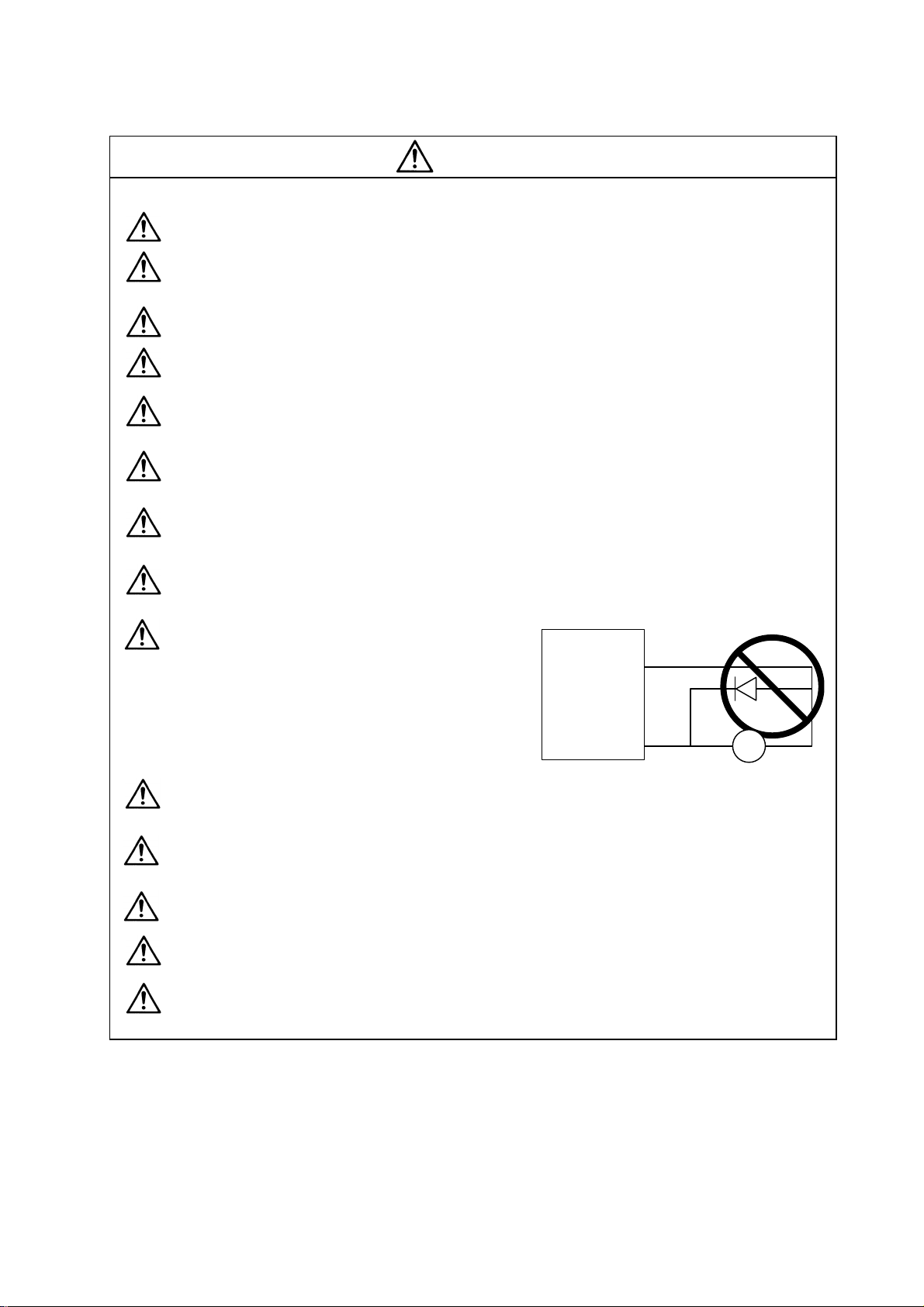
When using an inductive load such as a relay, always connect a diode as a noise measure
parallel to the load.
When using a capacitance load such as a lamp, always connect a protective resistor as a noise
measure serial to the load.
Do not reverse the direction of a diode which
connect to a DC relay for the control output
signals to suppress a surge. Connecting it
backwards could cause the drive unit to
Drive unit
COM
(24VDC)
Diode reverse orientation
malfunction so that signals are not output, and
emergency stop and other safety circuits are
inoperable.
Control output
signal
Do not connect/disconnect the cables connected between the units while the power is ON.
Securely tighten the cable connector fixing screw or fixing mechanism. An insecure fixing could
cause the cable to fall off while the power is ON.
When using a shielded cable instructed in the connection manual, always ground the cable with
a cable clamp, etc.
Always separate the signals wires from the drive wire and power line.
Use wires and cables that have a wire diameter, heat resistance and flexibility that conforms to
the system.
RA
Page 9
(3) Trial operation and adjustment
Check and adjust each program and parameter before starting operation. Failure to do so could
lead to unforeseen operation of the machine.
Do not make remarkable adjustments and changes as the operatio n could become unstable.
The usable motor and unit combination is predetermined. Always check the models before
starting trial operation.
If the axis is unbalanced due to gravity, etc., balance the axis using a counterbalance, etc.
The linear servomotor does not have a stopping device such as magnetic brakes. Install a
stopping device on the machine side.
(4) Usage methods
Install an external emergency stop circuit so that the operation can be stopped and power
shut off immediately.
Turn the power OFF immediately if smoke, abnormal noise or odors are generated from the unit
or motor.
Unqualified persons must not disassemble or repair the unit.
CAUTION
Never make modifications.
Reduce magnetic damage by installing a noise filter. The electronic devices used near the unit
could be affected by magnetic noise.
Use the unit, motor and regenerative resistor with the designated combination. Failure to do so
could lead to fires or trouble.
The brake (magnetic brake) assembled into the servomotor are for holding, and must not be
used for normal braking. Do not apply the brakes in the servo ON state. Doing so will lead to a
drop in the brake life. Always turn the servo OFF before applying the brakes.
There may be cases when holding is not possible due to the magnetic brake's life or the
machine construction (when ball screw and servomotor are coupled via a timing belt, etc.).
Install a stop device to ensure safety on the machine side.
After changing the programs/parameters or after maintenance and inspection, always test the
operation before starting actual operation.
Do not enter the movable range of the machine during automatic operation. Never place body
parts near or touch the spindle during rotation.
Follow the power supply specification conditions given in the separate specifications manual for
the power (input voltage, input frequency, tolerable sudden power failure time, etc.).
Page 10
(5) Troubleshooting
If a hazardous situation is predicted during power failure or product trouble, use a servomotor
with magnetic brakes or install an external brake mechanism.
Use a double circuit configuration
that allows the operation circuit for
the magnetic brakes to be operated
even by the external emergency
stop signal.
CAUTION
Shut off with the servomotor
brake control output.
Servomotor
Magnetic
brake
Shut off with NC brake
control PLC output.
MBR
EMG
24VDC
Always turn the input power OFF when an alarm occurs.
Never go near the machine after restoring the power after a power failure, as the machine
could start suddenly. (Design the machine so that personal safety can be ensured even if the
machine starts suddenly.)
(6) Maintenance, inspection and part replacement
Always backup the programs and parameters in the CNC device before starting maintenance
or inspections.
The capacity of the electrolytic capacitor will drop over time due to self-discharging, etc. To
prevent secondary disasters due to failures, replacing this part every five years when used
under a normal environment is recommended. Contact the Service Center or Service Station
for replacement.
Do not perform a megger test (insulation resistance measurement) during inspections.
If the battery low warning is issued, back up the machining programs, tool data and
parameters with an input/output unit, and then replace the battery.
Do not short circuit, charge, overheat, incinerate or disassemble the battery.
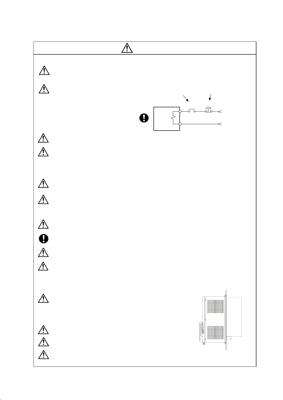
The heat radiating fin used in the 37kW and smaller unit contains substitute Freon as the
refrigerant.
Take care not to damage the heat radiating fin during maintenance and replacement work.
(7) Disposal
Do not dispose of this unit as general industrial waste. The
37kW and smaller unit with heat radiating fin protruding from
the back of the unit contains substitute Freon. Do not dispose
of this type of unit as general industrial waste. Always return
to the Service Center or Service Station.
Heat
radiating
fin
Do not disassemble the unit or motor.
Dispose of the battery according to local laws.
Always return the secondary side (magnet side) of the linear servomotor to the Service
Center or Service Station.
Page 11

CAUTION
(8) Transportation
(9) General precautions
The drawings given in this Specifications and Maintenance Instruction Manual show the covers and
safety partitions, etc., removed to provide a clearer explanation. Always return the covers or partitions to
their respective places before starting operation, and always follow the instructions given in this manual.
The unit and motor are precision parts and must be handled carefully.
According to a United Nations Advisory, the battery unit and battery must be transported
according to the rules set forth by the International Civil Aviation Organization (ICAO),
International Air Transportation Association (IATA), International Maritime Organization
(IMO), and United States Department of Transportation (DOT), etc.
Page 12

CONTENTS
1. Preface
1-1 Inspection at purchase.................................................................................................................. 1-2
1-1-1 Package contents ................................................................................................................. 1-2
1-1-2 Rating nameplate.................................................................................................................. 1-2
1-1-3 Power supply unit model....................................................................................................... 1-2
1-1-4 Servo drive unit model.......................................................................................................... 1-3
1-1-5 Spindle drive unit model........................................................................................................ 1-3
1-2 Explanation of each part............................................................................................................... 1-4
1-2-1 Explanation of each power supply unit part.......................................................................... 1-4
1-2-2 Explanation of each servo drive unit part.............................................................................. 1-5
1-2-3 Explanation of each spindle drive unit part........................................................................... 1-5
2. Wiring and Connection
2-1 Part system connection diagram.................................................................................................. 2-3
2-2 Main circuit terminal block/control circuit connector..................................................................... 2-5
2-2-1 Connector pin assignment.................................................................................................... 2-5
2-2-2 Names and applications of main circuit termi nal block signals and control circuit connectors 2-7
2-2-3 How to use the control circuit terminal block (MDS-CH-SP-750)......................................... 2-8
2-3 NC and drive unit connection ....................................................................................................... 2-10
2-4 Motor and detector connection..................................................................................................... 2-11
2-4-1 Connection of HC-H Series .................................................................................................. 2-11
2-4-2 Connection of the spindle motor........................................................................................... 2-14
2-4-3 Connection of the linear servomotor LM-NP Series............................................................. 2-15
2-5 Connection of power supply......................................................................................................... 2-16
2-5-1 Standard connection............................................................................................................. 2-16
2-5-2 DC connection bar................................................................................................................ 2-18
2-5-3 Two-part system control of power supply unit....................................................................... 2-19
2-5-4 Using multiple power supply units ........................................................................................ 2-20
2-6 Connection of AC reactor............................................................................................................. 2-21
2-6-1 Features of the AC reactor.................................................................................................... 2-21
2-6-2 Wiring of AC reactor.............................................................................................................. 2-21
2-7 Wiring of contactors...................................................................................................................... 2-22
2-7-1 Contactor power ON sequences........................................................................................... 2-23
2-7-2 Contactor shutoff sequences................................................................................................ 2-23
2-7-3 Contactor control signal (MC1) output circuit........................................................................ 2-24
2-8 Wiring of the motor brake............................................................................................................. 2-25
2-8-1 Motor brake release sequence............................................................................................. 2-25
2-8-2 Control during the servo OFF command .............................................................................. 2-25
2-8-3 Operation sequences when an emergency stop occurs....................................................... 2-25
2-8-4 Motor brake control connector (CN20) output circuit............................................................ 2-26
2-9 Wiring of an external emergency stop.......................................................................................... 2-27
2-9-1 External emergency stop setting ......................................................................................... . 2-27
2-9-2 Operation sequences of CN23 external emergency stop function....................................... 2-28
2-9-3 Example of emergency stop circuit.......................................................................................
2-10 Connecting the Grounding Cable............................................................................................... 2-30
2-10-1 Connecting the Frame Ground (FG)................................................................................... 2-30
2-10-2 Grounding cable size.......................................................................................................... 2-30
3. Installation
3-1 Installation of the units.................................................................................................................. 3-2
3-1-1 Environmental conditions...................................................................................................... 3-2
3-1-2 Installation direction and clearance ...................................................................................... 3-3
3-1-3 Prevention of entering of foreign matter............................................................................... 3-3
3-1-4 Panel installation hole work drawings (Panel cut drawings)................................................. 3-4
3-1-5 Heating value........................................................................................................................ 3-5
3-1-6 Heat radiation countermeasures........................................................................................... 3-6
2-29
Page 13

3-2 Installation of servomotor/spindle motor....................................................................................... 3-7
3-2-1 Environmental conditions...................................................................................................... 3-7
3-2-2 Cautions for mounting load (prevention of impact on shaf t)................................................. 3-8
3-2-3 Installation direction.............................................................................................................. 3-8
3-2-4 Tolerable load of axis............................................................................................................ 3-9
3-2-5 Oil and waterproofing measures........................................................................................... 3-10
3-2-6 Cable stress.......................................................................................................................... 3-12
3-3 Installing the linear servomotor..................................................................................................... 3-13
3-3-1 Installation environment........................................................................................................ 3-13
3-3-2 Installing the linear servomotor............................................................................................. 3-13
3-3-3 Cooling the linear servomotor............................................................................................... 3-15
3-4 Noise measures............................................................................................................................ 3-16
4. Setup
4-1 Initial setup.................................................................................................................................... 4-2
4-1-1 Setting the rotary switch........................................................................................................ 4-2
4-1-2 Transition of LED display after power is turned ON.............................................................. 4-3
4-2 Servo drive unit initial parameter settings..................................................................................... 4-4
4-2-1 List of servo parameters....................................................................................................... 4-4
4-2-2 Limitations to electronic gear setting value........................................................................... 4-19
4-2-3 Setting excessive detection error width................................................................................ 4-19
4-2-4 Setting motor and detector model......................................................................................... 4-20
4-2-5 Setting servo specifications.................................................................................................. 4-21
4-2-6 Initial setup of the linear servo system.................................................................................. 4-22
4-2-7 Standard parameter list according to motor.......................................................................... 4-31
4-3 Spindle drive unit initial parameter settings.................................................................................. 4-33
4-3-1 List of spindle parameters..................................................................................................... 4-33
4-3-2 Details of bit-corresponding parameters............................................................................... 4-50
4-3-3 Setting spindle drive unit and motor model .......................................................................... 4-54
4-3-4 Spindle specification parameters screen.............................................................................. 4-55
4-3-5 Spindle control signals.......................................................................................................... 4-58
5. Adjustment
5-1 Servo adjustment data output function (D/A output) .................................................................... 5-2
5-1-1 D/A output specifications ...................................................................................................... 5-2
5-1-2 Setting the output data.......................................................................................................... 5-2
5-1-3 Setting the output magnification ........................................................................................... 5-2
5-2 Gain adjustment............................................................................................................................ 5-3
5-2-1 Current loop gain .................................................................................................................. 5-3
5-2-2 Speed loop gain.................................................................................................................... 5-3
5-2-3 Position loop gain.................................................................................................................. 5-5
5-3 Characteristics improvement........................................................................................................ 5-8
5-3-1 Optimal adjustment of cycle time.......................................................................................... 5-8
5-3-2 Vibration suppression measures .......................................................................................... 5-11
5-3-3 Improving the cutting surface precision................................................................................ 5-15
5-3-4 Improvement of protrusion at quadrant changeover............................................................. 5-23
5-3-6 Improvement of characteristics during acceleration/deceleration ........................................ 5-26
5-4 Settings for emergency stop......................................................................................................... 5-29
5-4-1 Vertical axis drop prevention control..................................................................................... 5-29
5-4-2 Deceleration control.............................................................................................................. 5-31
5-4-3 Dynamic braking stop ........................................................................................................... 5-32
5-5 Collision detection function........................................................................................................... 5-33
5-6 Spindle adjustment data output function (D/A output).................................................................. 5-36
5-6-1 D/A output specifications ...................................................................................................... 5-36
5-6-2 Parameter settings................................................................................................................ 5-36
5-6-3 Output data settings.............................................................................................................. 5-36
5-6-4 Setting the output magnification ........................................................................................... 5-37
Page 14

5-7 Spindle adjustment....................................................................................................................... 5-40
5-7-1 Items to check during trial operation..................................................................................... 5-40
5-7-2 Adjusting the spindle rotation speed..................................................................................... 5-40
5-7-3 Adjusting the acceleration/deceleration................................................................................ 5-40
5-7-4 Adjusting the orientation....................................................................................................... 5-42
5-7-5 Synchronous tap adjustment................................................................................................ 5-49
5-7-6 Z-phase (magnetic) automatic adjustment (Only when using IPM spindle motor)............... 5-51
5-7-7 PLG automatic adjustment ................................................................................................... 5-51
5-7-8 Calculating the theoretical acceleration/deceleration........................................................... 5-52
5-8 Spindle specifications ................................................................................................................... 5-54
5-8-1 Spindle coil changeover........................................................................................................ 5-54
6. Dedicated Options
6-1 Dynamic brake unit .................................................................................................................. 6-2
6-1-2 Outline dimension drawings of dynamic brake unit.............................................................. 6-3
6-2 Battery option................................................................................................................................ 6-4
6-2-1 Battery unit............................................................................................................................ 6-4
6-2-2 Connection............................................................................................................................ 6-8
6-2-3 Dedicated battery cable drawing .......................................................................................... 6-8
6-3 Cables and connectors................................................................................................................. 6-9
6-3-1 Cable option list .................................................................................................................... 6-10
6-3-2 Connector outline dimension drawings................................................................................. 6-14
6-3-3 Flexible conduits................................................................................................................... 6-21
6-3-4 Cable wire and assembly...................................................................................................... 6-23
6-3-5 Option cable connection diagram......................................................................................... 6-25
6-3-6 Main circuit cable connection drawing.................................................................................. 6-28
6-4 Scale I/F unit................................................................................................................................. 6-29
6-4-1 Outline................................................................................................................................... 6-29
6-4-2 Model configuration............................................................................................................... 6-29
6-4-3 List of specifications.............................................................................................................. 6-29
6-4-4 Unit outline dimension drawing............................................................................................. 6-30
6-4-5 Description of connector ....................................................................................................... 6-30
6-4-6 Example of detector conversion unit connection.................................................................. 6-31
6-4-7 Cables................................................................................................................................... 6-32
6-5 Magnetic pole detection unit......................................................................................................... 6-36
6-5-1 Outline................................................................................................................................... 6-36
6-5-2 Model configuration............................................................................................................... 6-36
6-5-3 List of specifications.............................................................................................................. 6-36
6-5-4 Outline dimensions ............................................................................................................... 6-36
6-5-5 Assignment of connector pins............................................................................................... 6-37
6-5-6 Installing onto the linear servomotor..................................................................................... 6-37
6-6 Detectors ...................................................................................................................................... 6-38
6-6-1 List of detector specifications................................................................................................ 6-38
6-6-2 Outline dimension drawings.................................................................................................. 6-39
6-6-3 Cable connection diagram.................................................................................................... 6-41
6-6-4 Maintenance .............................................................................................................
6-7 Spindle option specification parts................................................................................................. 6-43
6-7-1 Magnetic sensor orientation (one-point orientation)............................................................. 6-44
6-7-2 Multi-point orientation using encoder (4096-point orientation)............................................. 6-48
6-7-3 Multi-point orientation using motor built-in encoder (4096-point orientation) ....................... 6-51
6-7-4 Contour control (C axis control) encoder.............................................................................. 6-53
6-7-5 Integrated rotary encoder (Special order part)...................................................................... 6-56
6-8 AC reactor..................................................................................................................................... 6-57
6-8-1 Combination with power supply unit..................................................................................... 6-57
6-8-2 Outline dimension drawings.................................................................................................. 6-57
............ 6-42
Page 15

7. Peripheral Devices
7-1 Selection of wire ........................................................................................................................... 7-2
7-1-1 Example of wires by unit....................................................................................................... 7-2
7-2 Selection of main circuit breaker and contactor ........................................................................... 7-5
7-2-1 Selection of earth leakage breaker....................................................................................... 7-5
7-2-2 Selection of no-fuse breaker................................................................................................. 7-6
7-2-3 Selection of contactor ........................................................................................................... 7-7
7-3 Control circuit related.................................................................................................................... 7-8
7-3-1 Circuit protector..................................................................................................................... 7-8
7-3-2 Fuse protection..................................................................................................................... 7-9
7-3-3 Relays................................................................................................................................... 7-10
7-3-4 Surge absorber..................................................................................................................... 7-11
8. Troubleshooting
8-1 Points of caution and confirmation ............................................................................................... 8-2
8-2 Troubleshooting at start up........................................................................................................... 8-3
8-3 Protective functions list of units .................................................................................................... 8-4
8-3-1 List of alarms......................................................................................................................... 8-4
8-3-2 List of warnings..................................................................................................................... 8-16
8-3-3 Protection functions and resetting methods ......................................................................... 8-17
8-3-4 Parameter numbers during initial parameter error................................................................ 8-19
8-3-5 Troubleshooting.................................................................................................................... 8-20
8-4 Spindle system troubleshooting.................................................................................................... 8-39
8-4-1 Introduction........................................................................................................................... 8-39
8-4-2 First step............................................................................................................................... 8-39
8-4-3 Second step.......................................................................................................................... 8-40
8-4-4 When there is no alarm or warning....................................................................................... 8-41
9. Characteristics
9-1 Overload protection characteristics.............................................................................................. 9-2
9-1-1 Servomotor (HC-H series) .................................................................................................... 9-2
9-1-2 Linear servomotor (LM-NP Series)....................................................................................... 9-9
9-2 Duty characteristics ...................................................................................................................... 9-10
9-3 Magnetic brake characteristics..................................................................................................... 9-14
9-4 Dynamic brake characteristics...................................................................................................... 9-17
9-4-1 Deceleration torque............................................................................................................... 9-17
9-4-2 Determining the coasting amount with emergency stop....................................................... 9-18
9-5 Vibration class .............................................................................................................................. 9-20
10. Specifications
10-1 Power supply unit/drive unit........................................................................................................ 10-2
10-1-1 Installation environment conditions..................................................................................... 10-2
10-1-2 Servo drive unit................................................................................................................... 10-2
10-1-3 Spindle drive unit................................................................................................................. 10-3
10-1-4 Power supply unit................................................................................................................ 10-3
10-1-5 Outline dimension drawings................................................................................................ 10-4
10-1-6 Terminal layout.................................................................................................................... 10-8
10-1-7 The combination of servo drive unit and a motor ............................................................... 10-9
10-2 Servomotor................................................................................................................................. 10-10
10-2-1 Specifications list................................................................................................................. 10-10
10-2-2 Torque characteristics......................................................................................................... 10-12
10-2-3 Model configuration............................................................................................................. 10-14
10-2-4 Outline dimension drawings................................................................................................ 10-15
Page 16

10-3 Linear servomotor....................................................................................................................... 10-21
10-3-1 List of specifications............................................................................................................ 10-21
10-3-2 Outline dimension drawings................................................................................................ 10-22
11. Selection
11-1 Selection of servomotor.............................................................................................................. 11-2
11-1-1 Servomotor.......................................................................................................................... 11-2
11-1-2 Regeneration methods........................................................................................................ 11-3
11-1-3 Motor series characteristics ................................................................................................ 11-4
11-1-4 Servomotor precision.......................................................................................................... 11-4
11-1-5 Selection of servomotor capacity........................................................................................ 11-6
11-1-6 Example of servo selection................................................................................................. 11-10
11-1-7 Motor shaft conversion load torque..................................................................................... 11-13
11-1-8 Expressions for load inertia calculation............................................................................... 11-14
11-1-9 Other precautions................................................................................................................ 11-15
11-2 Selection of linear servomotor.................................................................................................... 11-16
11-2-1 Maximum feedrate .............................................................................................................. 11-16
11-2-2 Maximum thrust................................................................................................................... 11-16
11-2-3 Continuous thrust................................................................................................................ 11-18
11-3 Selection of the power supply unit.............................................................................................. 11-20
11-3-1 Selection of the power supply unit capacity ........................................................................ 11-20
11-3-2 Selection with continuous rated capacity............................................................................ 11-20
11-3-3 Selection with maximum momentary rated capacity ........................................................... 11-22
12. Inspection
12-1 Inspections.................................................................................................................................. 12-2
12-2 Service parts............................................................................................................................... 12-2
12-3 Daily inspections......................................................................................................................... 12-3
12-3-1 Maintenance tools............................................................................................................... 12-3
12-3-2 Inspection positions ............................................................................................................ 12-3
12-4. Replacement methods of units and parts..................................................................................... 12-4
12-4-1 Drive unit and power supply unit replacements..................................................................... 12-4
12-4-2 Battery unit replacements...................................................................................................... 12-4
12-4-3 Cooling fan replacements...................................................................................................... 12-4
Appendix 1. Compliance to EC Directives
1. European EC Directives.................................................................................................................... A1-2
2. Cautions for EC Directive compliance............................................................................................... A1-2
Appendix 2. EMC Installation Guidelines
1. Introduction........................................................................................................................................ A2-2
2. EMC Instructions............................................................................................................................... A2-2
3. EMC Measures.................................................................................................................................. A2-3
4. Measures for panel structure............................................................................................................. A2-3
4.1 Measures for control box unit................................................................................................... A2-3
4.2 Measures for door.................................................................................................................... A2-4
4.3 Measures for operation board panel........................................................................................ A2-4
4.4 Shielding of the power supply input section............................................................................. A2-4
5. Measures for various cables ............................................................................................................. A2-5
5.1 Measures for wiring in box ....................................................................................................... A2-5
5.2 Measures for shield treatment.................................................................................................. A2-5
5.3 Servomotor power cable .......................................................................................................... A2-6
5.4 Servomotor feedback cable ..................................................................................................... A2-6
5.5 Spindle motor power cable....................................................................................................... A2-7
5.6 Cable between control box and operation board panel........................................................... A2-7
Page 17

6. EMC Countermeasure Parts ............................................................................................................. A2-8
6.1 Shield clamp fitting................................................................................................................... A2-8
6.2 Ferrite core............................................................................................................................... A2-9
6.3 Power line filter......................................................................................................................... A2-10
6.4 Surge protector......................................................................................................................... A2-12
Appendix 3. EC Declaration of conformity
1. Low voltage equipment...................................................................................................................... A3-2
2. Electromagnetic compatibility............................................................................................................ A3-12
Appendix 4. Instruction Manual for Compliance with UL/c-UL Standard
1. UL/c-UL listed products..................................................................................................................... A4-2
2. Operation surrounding air ambient temperature ............................................................................... A4-3
3. Notes for AC servo/spindle system................................................................................................... A4-3
3.1 General Precaution .................................................................................................................. A4-3
3.2 Installation................................................................................................................................ A4-3
3.3 Short-circuit ratings .................................................................................................................. A4-3
3.5 Field Wiring Reference Table for Input and Output.................................................................. A4-4
3.6 Motor Over Load Protection..................................................................................................... A4-6
3.7 Flange of servomotor ............................................................................................................... A4-7
3.8 Spindle Drive / Motor Combinations......................................................................................... A4-7
4. AC Servo/Spindle System Connection.............................................................................................. A4-8
Appendix 5. Higher Harmonic Suppression Measure Guidelines
1. Calculating the equivalent capacity of the higher harmonic generator ............................................. A5-3
1.1 Calculating the total equivalent capacity (Step 1).................................................................... A5-3
1.2 Calculating the higher harmonic current flow (Step 2)............................................................. A5-4
Appendix 6. Transportation Restrictions for Lithium Batteries
Appendix 6-1 Transportation restrictions for lithium batteries ............................................................ A6-2
Appendix 6-1-1 Restriction for packing.......................................................................................... A6-2
Appendix 6-1-2 Issuing domestic law of the United State for primary lithium battery transportation A6-5
Appendix 7. Compliance with China Compulsory Product Certification (CCC Certification) System
Appendix 7-1 Outline of China Compulsory Product Certification System......................................... A7-2
Appendix 7-2 First Catalogue of Products subject to Compulsory Product Certification ................... A7-2
Appendix 7-3 Precautions for Shipping Products...............................................................................
Appendix 7-4 Application for Exemption............................................................................................. A7-4
Appendix 7-5 Mitsubishi NC Product Subject to/Not Subject to CCC Certification............................ A7-5
A7-3
Page 18

1. Preface
1-1 Inspection at purchase....................................................................................................................... 1-2
1-1-1 Package contents........................................................................................................................1-2
1-1-2 Rating nameplate........................................................................................................................ 1-2
1-1-3 Power supply unit model.............................................................................................................1-2
1-1-4 Servo drive unit model................................................................................................................. 1-3
1-1-5 Spindle drive unit model.............................................................................................................. 1-3
1-2 Explanation of each part ....................................................................................................................1-4
1-2-1 Explanation of each power supply unit part ................................................................................ 1-4
1-2-2 Explanation of each servo drive unit part.................................................................................... 1-5
1-2-3 Explanation of each spindle drive unit part ................................................................................. 1-5
1 - 1
Page 19
1. Preface
1-1 Inspection at purchase
Open the package, and read the rating nameplates to confirm that the drive units, power supply unit and
servomotor are as ordered.
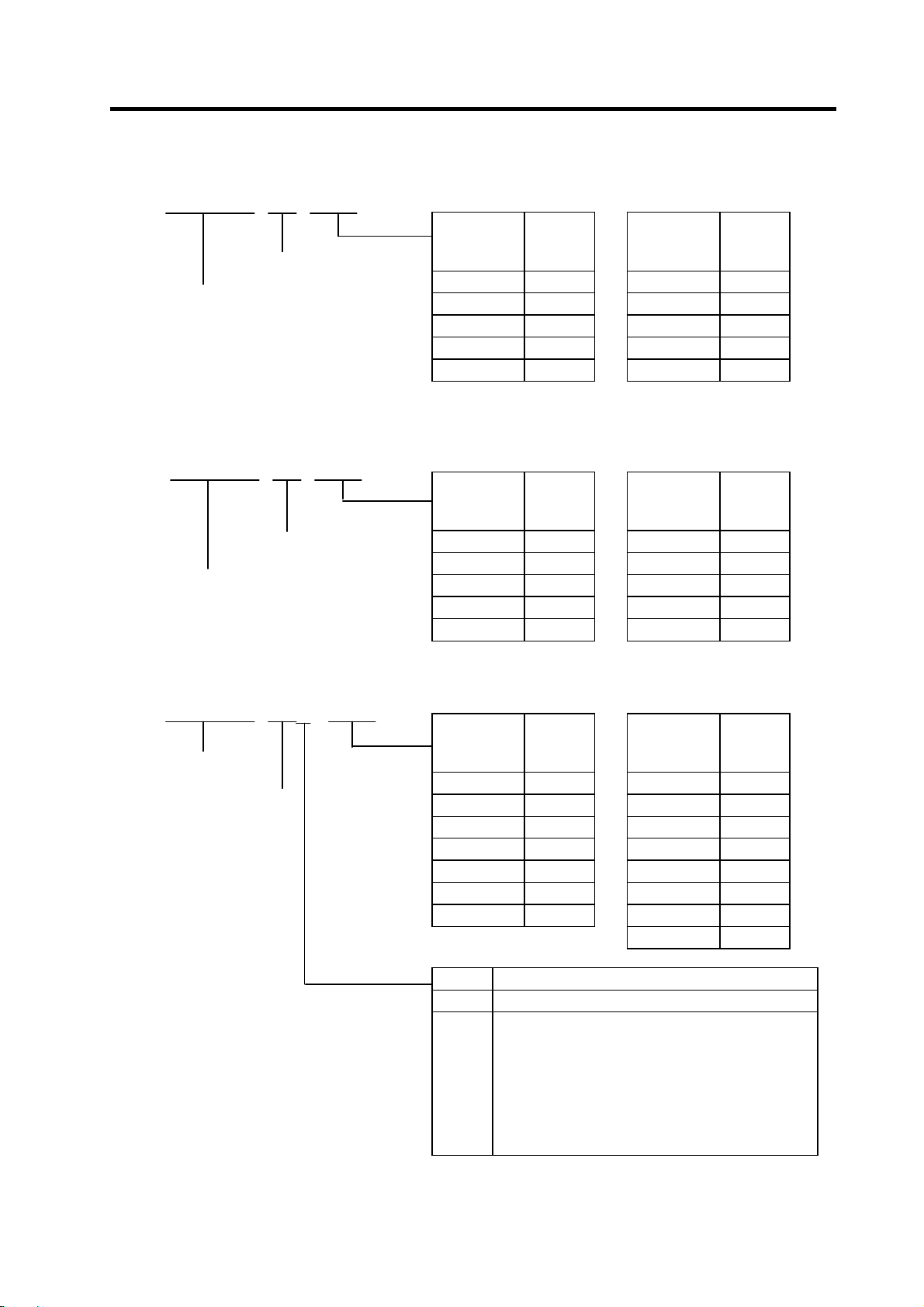
1-1-1 Package contents
Packaged parts Qty. Packaged parts Qty.
Power supply unit 1 Servo drive unit 1
Servo/spindle motor 1 Spindle drive unit 1
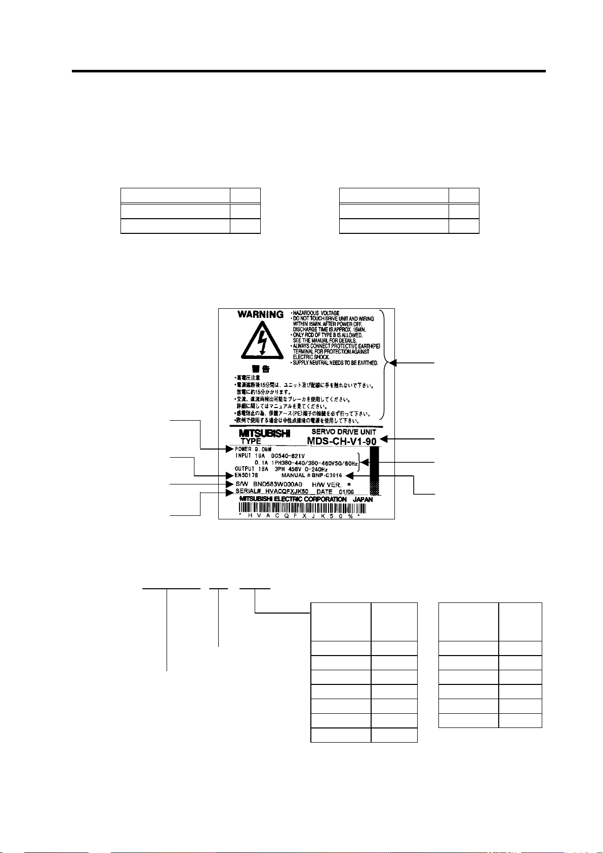
1-1-2 Rating nameplate
The rating nameplate is attached to the front of the unit.
The following rating nameplate is for the servo drive unit. The same matters are indicated on the power
supply unit and spindle drive unit.
Unit Capacity
Global industrial
standards
Software version
Serial No., Date of
manufacture
1-1-3 Power supply unit model
MDS - CH - CV - [ ]
Power supply unit
Series
(Note) DC connection bar is required. Always install a large capacity drive unit in the left
side of power supply unit, and connect with DC connection bar.
Rated
Symbol
37 2.2 260 22.0
55 3.7 300 26.0
75 5.5 370 30.0
110 7.5 450(Note) 37.0
150 11.0 550(Note) 45.0
185 15.0 750(Note) 55.0
220 18.5
Output
[kW]
Caution statement
Model
Input/output condition
Instruction manual No.
Rated
Symbol
Output
[kW]
1 - 2
Page 20
1-1-4 Servo drive unit model
MDS - CH - V1 - [ ]
1-axis servo drive unit
Series
(Note) DC connection bar is required. Always install a large capacity drive unit in the left side of
power supply unit, and connect with DC connection bar.
MDS - CH - V2 - [ ]
2-axis servo drive unit
Series
1-1-5 Spindle drive unit model
MDS - CH - SP[ ] - [ ]
Series
Spindle drive unit
(Note) DC connection bar is required. Always install a large capacity drive unit in the left side of
power supply unit, and connect with DC connection bar.
1. Preface
Symbol
Rated
Output
[kW]
Symbol
Rated
Output
[kW]
05 0.5 70 7.0
10 1.0 90 9.0
20 2.0 110 11.0
35 3.5 150 15.0
45 4.5 185(Note) 18.5
Symbol
Rated
Output
[kW]
Symbol
Rated
Output
[kW]
0505 0.5 / 0.5 3510 3.5 / 1.0
1005 1.0 / 0.5 3520 3.5 / 2.0
1010 1.0 / 1.0 3535 3.5 / 3.5
2010 2.0 / 1.0 4520 4.5 / 2.0
2020 2.0 / 2.0
4535 4.5 / 3.5
Symbol
Cont.
Rating
[kW]
Symbol
Cont.
Rating
[kW]
15 0.75 185 15.0
22 1.5 220 18.5
37 2.2 260 22.0
55 3.7 300 26.0
75 5.5 370(Note) 30.0
110 7.5 450(Note) 37.0
150 11.0 550(Note) 45.0
750(Note) 55.0
Symbol
Corresponding spindle motor
None Standard specifications part
H • High-speed part: 10000r/min or more
• C axis detector (1/10000
o
)
correspondence:
ERM280 (HEIDENHAIN)
• IPM spindle motor compatible
(Conventional SPM class has been
eliminated.)
1 - 3
Page 21
1
1. Preface
1-2 Explanation of each part
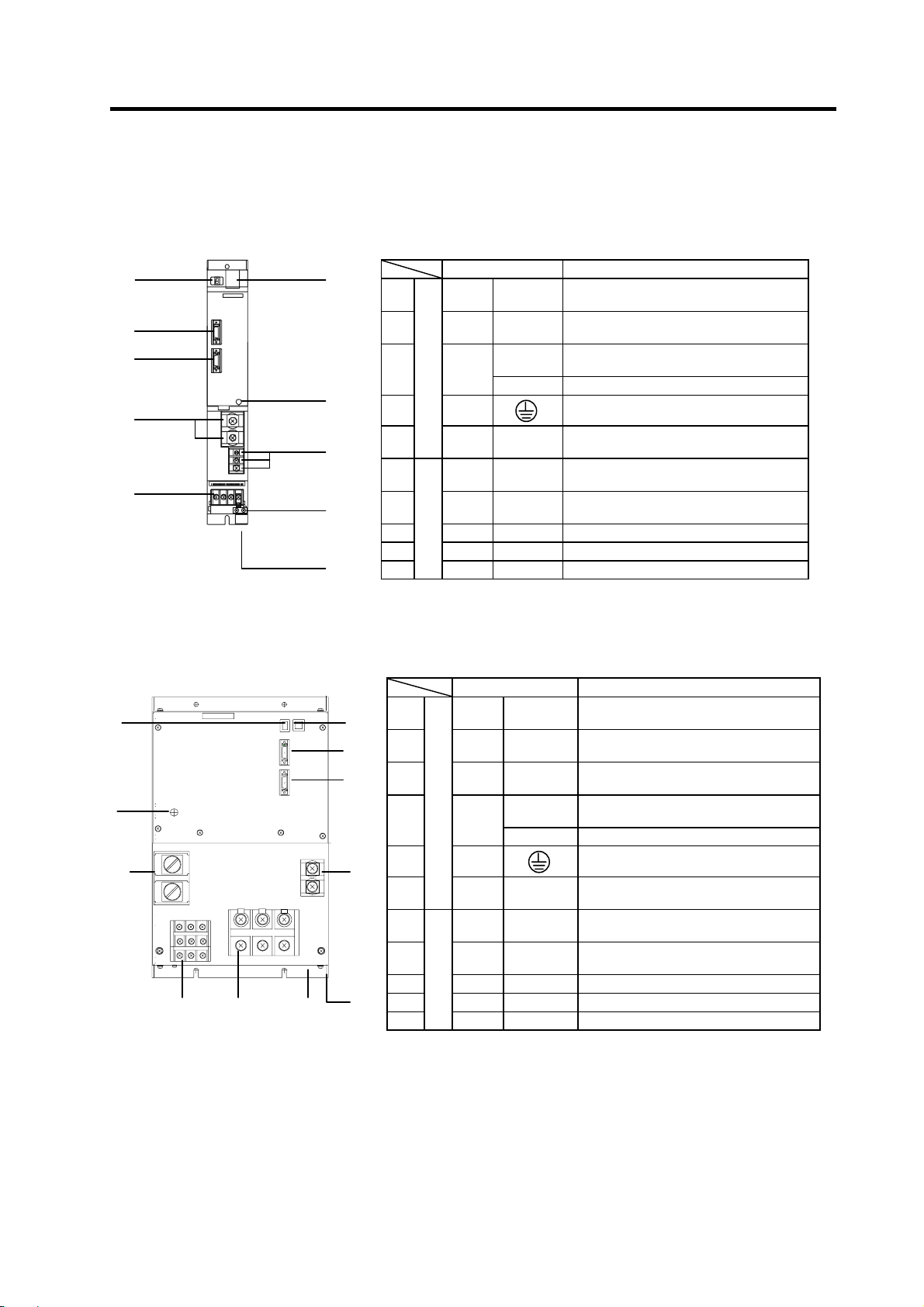
1-2-1 Explanation of each power supply unit part
<9>
<5>
<6>
<2>
<1>
<9>
<10>
<2>
<8>
<10>
<3>
<4>
<7>
-
<3>
<1>
<4>
Each part name
<1> TE1 L1, L2, L3
<2> TE2 L+, L–
<3> TE3
Main circuit
<4> PE
<10>
<5> CN4 ---
<6> CN9 --<7> CN23 --- External emergency stop input connector
<8> SW1 --- Power supply setting switch
Control circuit
<9>
Precautions
CN23 is located at the bottom of the power supply unit.
Each part name
<8>
<5>
<6>
<1> TE1 L1, L2, L3
-1
<2>
-2
<2>
<3> TE3
<4> PE
-2
<2>
<10>
<5> CN4 ---
<6> CN9 --<7> CN23 --- External emergency stop input connector
<8> SW1 --- Power supply setting switch
<7>
<9>
Precautions
CN23 is located at the bottom of the power supply unit.
TE2-2 is used to connect a 30kW or smaller drive unit.
Main circuit
Control circuit
The connector layout will differ according to the units being used.
Check each unit outline drawing for details.
Name Description
Power supply input terminal
(3-phase AC input)
Converter voltage output terminal
(DC output)
L11, L21
MC1 External contactor control terminal
CHARGE
---
LED --- Power supply status indication LED
TE2-1 L+, L–
TE2-2 L+, L–
LAMP
Name Description
L11, L21
MC1, MC2 External contactor control terminal
CHARGE
---
LED --- Power supply status indication LED
Control power input terminal (single-phase
AC input)
Grounding terminal
TE2 output charging/discharging circuit
indication LED
Servo/spindle communication connector
(master)
Servo/spindle communication connector
(slave)
Power supply input terminal
(3-phase AC input)
Voltage output terminal (DC output)
CV-450/550/750
Voltage output terminal (DC output)
CV-450/550
Control power input terminal
(single-phase AC input)
LAMP
Grounding terminal
TE2 output charging circuit indication
LED
Servo/spindle communication connector
(master)
Servo/spindle communication connector
(slave)
1 - 4
Page 22
r
r
r
1. Preface
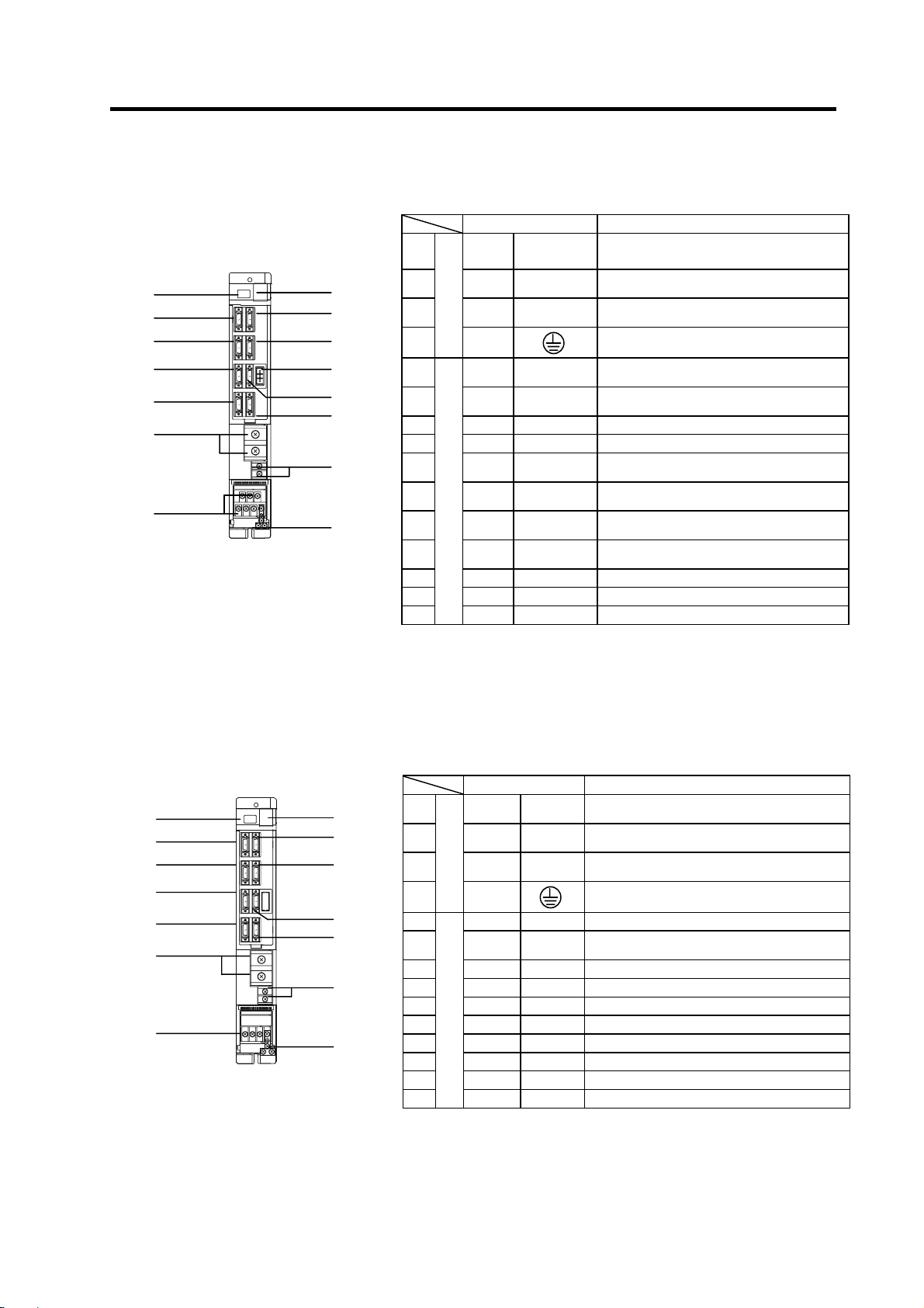
1-2-2 Explanation of each servo drive unit part
Each part name
<1> TE1
<15>
<5>
<8>
<9>
<10>
<2>
<1>
<14>
<6>
<7>
<13>
<11>
<12>
<3>
<4>
<2> TE2 L+, L–
<3> TE3 L11, L21
Main circuit
<4>
<5> CN1A --<6> CN1B ---
<7> CN4 --<8> CN9 ---
<9> CN2L --<10> CN2M --<11> CN3L --<12> CN3M ---
<13> CN20 --- Electromagnetic/dynamic brake connector
<14> SW1 --- Axis No. setting switch
<15>
Precautions
1. The connector names differ for the V1 drive unit.
(CN2L/CN3L → CN2/CN3, CN2M/CN3M → Not mounted)
The MU, MV and MW terminals are not provided. The LU, LV and LW terminals
are named U, V and W.
PE
Control circuit
LED --- Unit status indication LED
1-2-3 Explanation of each spindle drive unit part
<15>
<5>
<10>
<8>
<9>
<2>
<1>
<14>
<6>
<7>
<11>
<12>
<3>
<4>
Each part name
<1> TE1 U, V, W
<2> TE2 L+, L–
<3> TE3 L11, L21
<4>
<5> CN1A --<6> CN1B --<7> CN4 ---
<8> CN9 ---
<9> CN5 --<10> CN7 --<11> CN6 --<12> CN8 --<14> SW1 --- Axis No. setting switch
<15>
Precautions
Main circuit
PE
Control circuit
LED --- Unit status indication LED
The connector and terminal block layout will differ according to the
units being used.
Check each unit outline drawing for details.
Name Description
MU, MV, MW
LU, LV, LW
Name Description
Motor drive output terminal
(3-phase AC output)
Converter voltage input terminal
(DC input)
Control power input terminal
(single-phase AC input)
Grounding terminal
NC or upward axis communication
connecto
Battery unit/terminator
Lower axis communication connecto
Power supply communication connector
Maintenance connector (normally not used)
Motor side detector connection connector
(L axis)
Motor side detector connection connector
(M axis)
Machine side detector connection
connector (L axis)
Machine side detector connection
connector (M axis)
Motor drive output terminal
(3-phase AC output)
Converter voltage input terminal
(DC input)
Control power input terminal
(single-phase AC input)
Grounding terminal
NC or upward axis communication connector
Battery unit/terminator lower axis
communication connecto
Power supply communication connector
Maintenance connector (normally not used)
Internal PLG encoder connection connector
C axis control encoder connection connector
Magnetic sensor connection connector
CNC connection connector
1 - 5
Page 23

2. Wiring and Connection
2-1 Part system connection diagram........................................................................................................ 2-3
2-2 Main circuit terminal block/control circuit connector ..........................................................................2-5
2-2-1 Connector pin assignment ..........................................................................................................2-5
2-2-2 Names and applications of main circuit terminal block signals and control circuit connectors ..2-7
2-2-3 How to use the control circuit terminal block (MDS-CH-SP-750) ...............................................2-8
2-3 NC and drive unit connection...........................................................................................................2-10
2-4 Motor and detector connection ........................................................................................................2-11
2-4-1 Connection of HC-H Series.......................................................................................................2-11
2-4-2 Connection of the spindle motor ...............................................................................................2-14
2-4-3 Connection of the linear servomotor LM-NP Series.................................................................. 2-15
2-5 Connection of power supply............................................................................................................. 2-16
2-5-1 Standard connection .................................................................................................................2-16
2-5-2 DC connection bar.....................................................................................................................2-18
2-5-3 Two-part system control of power supply unit........................................................................... 2-19
2-5-4 Using multiple power supply units.............................................................................................2-20
2-6 Connection of AC reactor.................................................................................................................2-21
2-6-1 Features of the AC reactor........................................................................................................2-21
2-6-2 Wiring of AC reactor.................................................................................................................. 2-21
2-7 Wiring of contactors .........................................................................................................................2-22
2-7-1 Contactor power ON sequences............................................................................................... 2-23
2-7-2 Contactor shutoff sequences ....................................................................................................2-23
2-7-3 Contactor control signal (MC1) output circuit............................................................................2-24
2-8 Wiring of the motor brake.................................................................................................................2-25
2-8-1 Motor brake release sequence..................................................................................................2-25
2-8-2 Control during the servo OFF command...................................................................................2-25
2-8-3 Operation sequences when an emergency stop occurs...........................................................2-25
2-8-4 Motor brake control connector (CN20) output circuit................................................................2-26
2-9 Wiring of an external emergency stop .............................................................................................2-27
2-9-1 External emergency stop setting...............................................................................................2-27
2-9-2 Operation sequences of CN23 external emergency stop function ........................................... 2-28
2-9-3 Example of emergency stop circuit...........................................................................................2-29
2-10 Connecting the Grounding Cable................................................................................................... 2-30
2-10-1 Connecting the Frame Ground (FG).......................................................................................2-30
2-10-2 Grounding cable size...............................................................................................................2-30
2 - 1
Page 24
2. Wiring and Connection
DANGER
1. Wiring work must be done by a qualified technician.
2. Wait at least 15 minutes after turning the power OFF and check the voltage
with a tester, etc., before starting wiring. Failure to observe this could lead to
electric shocks.
3. Securely ground the drive units and servo/spindle motor with Class 3
grounding or higher.
4. Wire the drive units and servo/spindle motor after installation. Failure to
observe this could lead to electric shocks.
5. Do not damage, apply forcible stress, place heavy items on the cables or get
them caught. Failure to observe this could lead to electric shocks.
6. Always insulate the power terminal connection section. Failure to observe
this could lead to electric shocks.
1. Correctly and securely perform the wiring. Failure to do so could lead to
runaway of the servo/spindle motor.
2. Do not mistake the terminal connections.
Failure to observe this item could lead to ruptures or damage, etc.
3. Do not mistake the polarity ( + ,
– ). Failure to observe this item could lead to
ruptures or damage, etc.
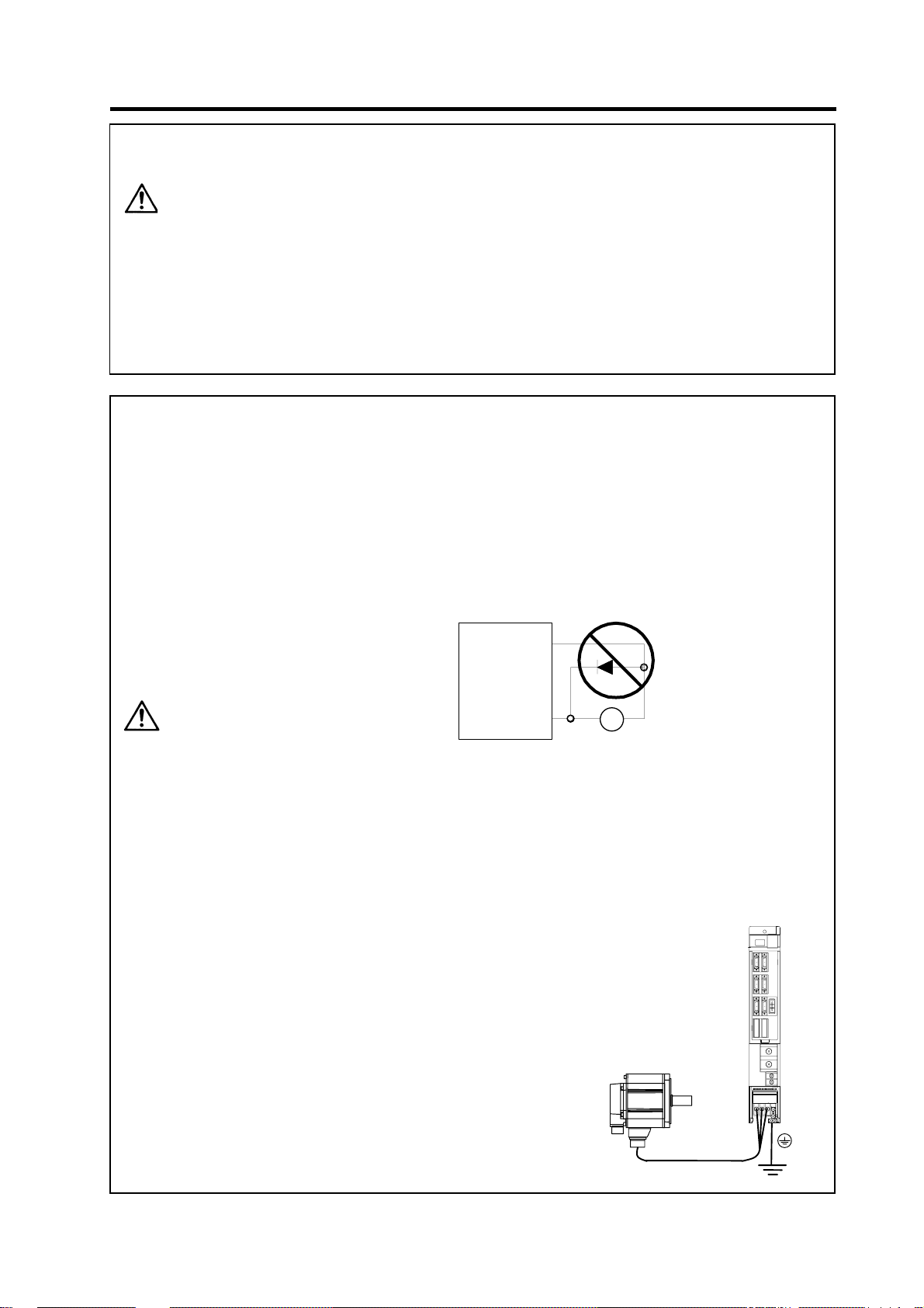
4. Do not mistake the direction of the diodes for the surge absorption installed
on the DC relay for the motor brake and contactor (magnetic contactor)
control. The signal might not be output when a failure occurs.
Drive uni t
COM
(24VDC)
CAUTION
Control output signal
RA
5. Electronic devices used near the drive units may receive magnetic
obstruction. Reduce the effect of magnetic obstacles by installing a noise
filter, etc.
6. Do not install a phase advancing capacitor, surge absorber or radio noise
filter on the power line (U, V, W) of the servo/spindle motor.
7. Do not modify this unit.
8. The half-pitch connector (CN1A, etc.) on the front of the drive units have the
same shape. If the connectors are connected incorrectly, faults could occur.
Make sure that the connection is correct.
9. When grounding the motor, connect to
the protective grounding terminal on the
drive units, and ground from the other
protective grounding terminal.
(Use one-point grounding)
Do not separately ground the connected
motor and drive unit as noise could be
generated.
2 - 2
Page 25
A
2. Wiring and Connection
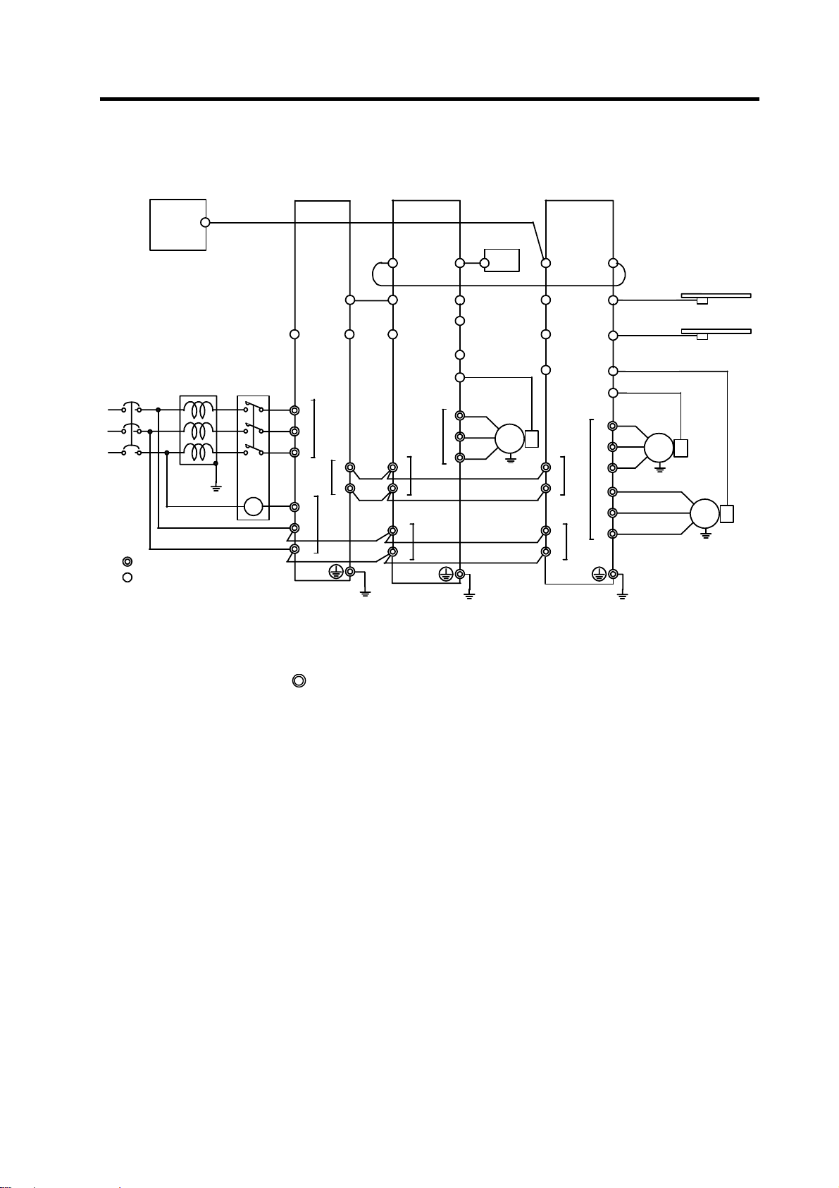
2-1 Part system connection diagram
Mitsubishi CNC
Ground
SH21 cable
External emergency
stop
Magnetic
contactor
Circuit breaker
R
S
T
Main circuit
Control circuit
SV1,2
(CSH21)
C reactor
CH-AL[ ] K
CH-AL[ ]K
(Note 1) The total length of the SH21 cable must be within 30m.
(Note 2) The connection method will differ according to the used motor.
(Note 3) When not using an absolute position detector, connect the terminal connector (R-TM).
(Note 4) The main circuit (
MC
MDS-CH-CV-[ ]
CN4
CN23
CN9
TE1
L1
L2
L3
TE2
L+
L-
TE3
MC1
L11
L21
Ground
MDS-CH-SP-[ ]
CN1B
CN1A
CN8
CN4
CN7
CN9
CN6
CN5
TE1
U
V
TE2
L+
L-
L11
L21
W
TE3
Ground
Battery unit
BT-[ ]
BT-[ ]
CN1A
SH21 cable
CNP5S cable
M
3~
MDS-CH-V2-[ ]
PLG
) and control circuit ({) are safely separated.
CN1A
CN4
CN9
CN20
TE2
L+
L-
TE3
L11
L21
CN1B
CN3M
CN3L
CN2L
CN2M
TE1
Ground
MU
MV
MW
LU
LV
LW
CNV13 cable
CNV13 cable
CNV12 cable
CNV12 cable
M
3~
Machine side
detector
Machine side
detector
Motor side
detector
M
3~
Motor side
detector
2 - 3
Page 26
S
S
2. Wiring and Connection
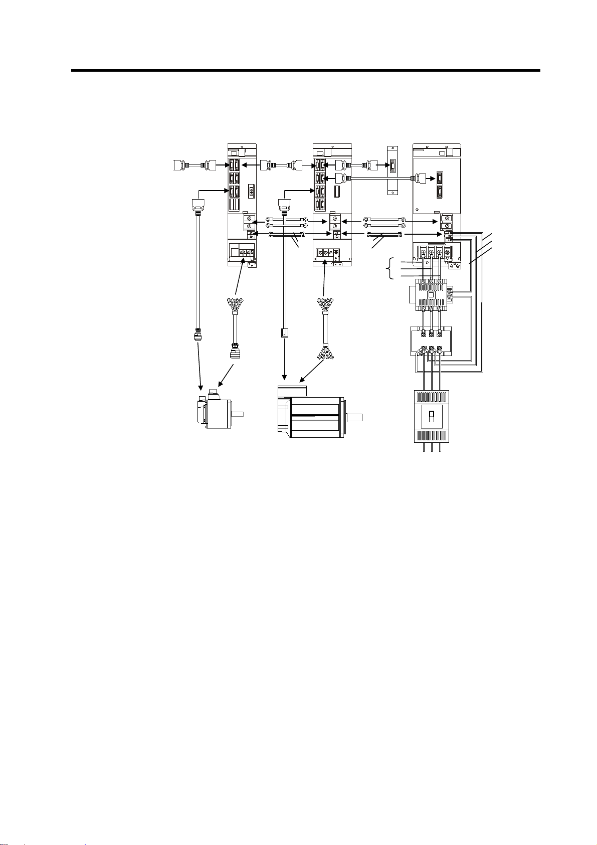
Example of actual wiring
Battery
unit
Power supply unit Spindle drive unitServo drive unit
NC controller
H21
H21
L11
L21
DRTE1
cable
L+
L-
L1
L2
L3
L+
L-
L11
L21
CNV12 cable
CNP5S cable
(Drive line)
DRSV cable
(Drive line)
DRSP cable
AC reactor
Servo motor
Spindle motor
L1 L2 L3
Note)
The main circuit cable wiring must be prepared by the user.
The wiring to the grounding cable is not shown. Refer to section "2-10 Wiring the Grounding Cable".
L11
L21
MC1
2 - 4
Page 27
2. Wiring and Connection
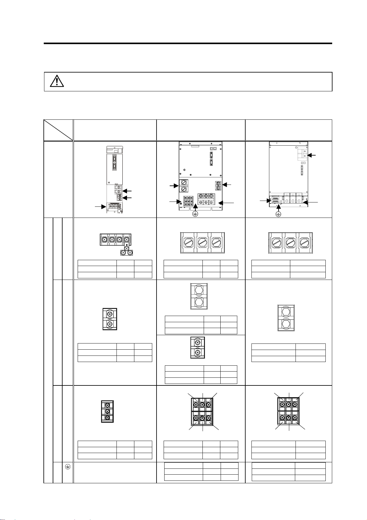
2-2 Main circuit terminal block/control circuit connector
CAUTION
2-2-1 Connector pin assignment
Power supply unit
Unit
Terminal
Terminal
position
MDS-CH-CV-37 to
<1>
Do not apply a voltage other than that specified in Instruction Manual on each
terminal. Failure to observe this item could lead to rupture or damage, etc.
MDS-CH-CV-370
<2>
<3>
<2>
<3>
MDS-CH-CV-450
MDS-CH-CV-550
1
<2>
<1>
MDS-CH-CV-750
<2>
2
<3>
<1>
<1> TE1
<1>
L1 L2 L3
37-185 220-370
Screw size M5×12 M8×14
Tightening torque 2.0Nm 6.0Nm
<2>
L+
L–
<2> TE2
37-185 220-370
Screw size M6×15 M6×15
Tightening torque 3.0Nm 3.0Nm
<3> TE3
Terminal specification/Pin assignment
<3>
PE
<1>
L1 L2 L3
450 550
Screw size M8×16 M10×20
Tightening torque 6.0Nm 11.0Nm
<2>1
L+
L–
450 550
Screw size M10×20 M10×20
Tightening torque 11.0Nm 11.0Nm
<2>2
L+
L–
450 550
Screw size M6×16 M6×16
Tightening torque 3.0Nm 3.0Nm
<3>
L1 L12 MC1
<1>
L1 L2 L3
750
Screw size M10×20
Tightening torque 11.0Nm
<2>
Screw size M10×20
Tightening torque 11.0Nm
<3>
750
L11 L12 MC1
L+
L–
L11
L21
MC1
L12 L22 MC2
37-185 220-370
Screw size M4×10 M4×10
Tightening torque 1.2Nm 1.2Nm
Refer to PE terminal of TE1.
450 550
Screw size M4×8M4×8
Tightening torque 1.2Nm 1.2Nm
450 550
Screw size M8×16 M10×20
Tightening torque 6.0Nm 11.0Nm
2 - 5
L12 L22 MC2
750
Screw size M4×8
Tightening torque 1.2Nm
750
Screw size M10×20
Tightening torque 11.0Nm
Page 28
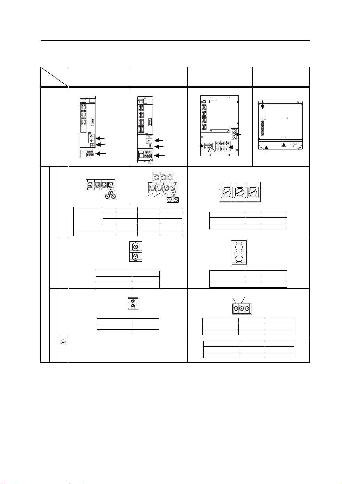
Servo/spindle drive unit
Unit
Terminal
Terminal
position
MDS-CH-V-150 or less
MDS-CH-SP-300 or less
<1> <1>
U V W
<2>
<3>
<1>
2. Wiring and Connection
MDS-CH-V2 Series
<2>
<3>
<1>
MU MV MW
MDS-CH-V1-185
MDS-CH-SP-370
MDS-CH-SP-450/550
<3>
<1>
<2>
<1>
U V W
MDS-CH-SP-750
<2>
<1> <3>
PE
<1> TE1
Corresponding
unit
Screw size M4×10 M5×12 M8×14
Tightening torque 1.2Nm 2.0Nm 6.0Nm
<2>
<2> TE2
Tightening torque 3.0Nm
<3> TE3
Terminal specification/Pin assignment
<3>
Tightening torque 1.2Nm
V1- 10-35 45-90 110-150
V2- 1010-4535 ---- ----
SP- 15-37 55-185 220-300
V1/V2/SP
Screw size M6×16
V1/V2/SP
Screw size M4×10
Refer to PE terminal of TE1.
LU LV LW
L+
L–
L11
L21
PE
370 450/550/750
Screw size M8×16 M10×20
Tightening torque 6.0Nm 11.0Nm
<2>
L+
L–
370 450/550/750
Screw size M10×20 M10×20
Tightening torque 11.0Nm 11.0Nm
<3>
Screw size M4×8 Refer to "2-2-3".
Tightening torque 1.2Nm Refer to "2-2-3".
Tightening torque 6.0Nm 11.0Nm
L11 L21
370/450/550 750
370 450/550/750
Screw size M8×16 M10×20
2 - 6
Page 29

2. Wiring and Connection
2-2-2 Names and applications of main circuit terminal block signals and control circuit
connectors
The following table shows the details for each terminal block signal.
Name Signal name Description
L1 . L2 . L3
L11 . L21
(L12 . L22)
MC1
(MC2)
U . V . W
LU . LV . LW
MU . MV . MW
Main circuit
power supply
Control circuit
power supply
Contactor
control
Motor output
Motor output
Protective
grounding (PE)
Main circuit power supply input terminal
Connect a 3-phase 380 to 480VAC, 50/60Hz power supply.
Control circuit power supply input terminal
Connect a single-phase 380 to 480VAC, 50/60Hz power supply.
Connect the same power supply phase for L11 and L12, and L21 and
L22.
Contactor control terminal
The MC1 terminal has the same phase as L21. Connect to a different
phase than the phase connected to L21. (Connect MC2 with L21.)
Servo/spindle motor power output terminal
The servo/spindle motor power terminal (U, V, W) is connected.
Servo motor power output terminal (L-axis/M-axis)
The servo/spindle motor power terminal (U, V, W) is connected.
Grounding terminal
The servomotor/spindle motor grounding terminal is connected and
grounded.
1. Always use one AC reactor per power supply unit.
Failure to observe this could lead to unit damage.
CAUTION
2. When sharing a breaker for several power supply units, of a short-circuit
fault occurs in a small capacity unit, the breaker could trip. This can be
hazardous, so do not share the breaker.
3. Be sure to use the breaker of proper capacity for each Power Supply Unit.
2 - 7
Page 30
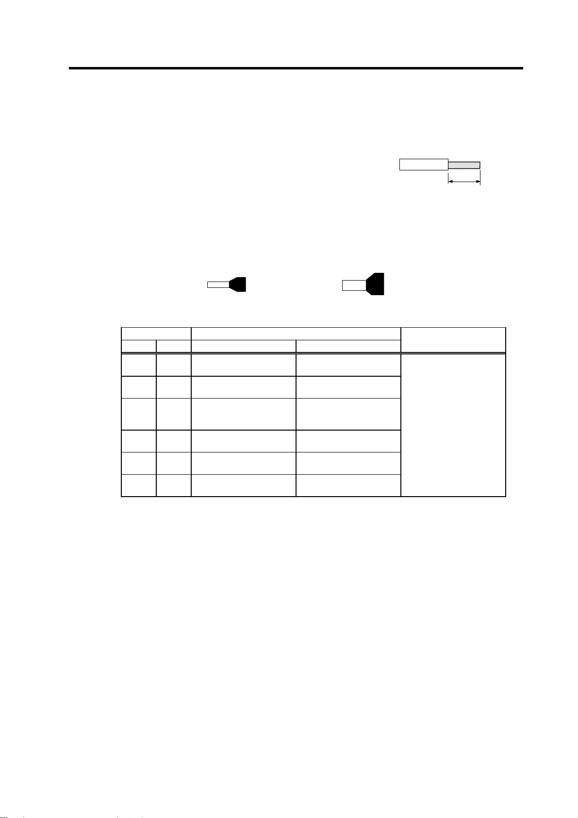
2. Wiring and Connection
2-2-3 How to use the control circuit terminal block (MDS-CH-SP-750)
The control power for the 75kW spindle unit is not connected to the terminal block, so wire according to
the following instructions.
<1> Treatment of wire end
Single wire: Peel the wire sheath, and use the wire.
(Wire size: 0.25 to 2.5 mm
2
)
Stranded wire: Peel the wire sheath, and then twist the core wires.
Take care to prevent short circuits with the
neighboring poles due to the fine strands of the core wires. Solder plating onto the
core wire section could cause a contact defect and must be avoided. (Wire size:
0.25 to 2.5 mm
2
)
Use a bar terminal and bundle the strands. (Made by Phoenix contact)
Length to peel
Approx. 10mm
Bar terminal for one wire
(Bar terminal phenol with insulation sleeve)
Wire size Bar terminal type
[mm2] AWG For one wire For two wires
0.25 24
0.5 20
0.75 18
1 18
1.5 16
2.5 14
<2> Connection method
Insert the core wire section of the wire into the opening, and tighten with a screwdriver so that the
wire does not come out. (Tightening torque: 0.5 to 0.6 N•m) When inserting the wire into the
opening, make sure that the terminal screw is sufficiently loose. When using a wire that is 1.5 mm
or less, two wires can be inserted into one opening.
AI0.25-6YE
AI0.25-8YE
AI0.5-6WH
AI0.5-8WH
AI0.75-6GY
AI0.75-8GY
AI1-6RD
AI1-8RD
AI1.5-6BK
AI1.5-8BK
AI2.5-8BU
AI2.5-8BU-1000
Bar terminal for two wires
(TWIN phenol with insulation sleeve)
–
–
AI-TWIN2×0.75-8GY
AI-TWIN2×0.75-10G
Y
AI-TWIN2×1-8RD
AI-TWIN2×1-10RD
AI-TWIN2×1.5-8BK
AI-TWIN2×1.5-12BK
AI-TWIN2×2.5-10BU
AI-TWIN2×2.5-13BU
Crimping tool
CRIMPFOX-UD6
2
2 - 8
Page 31

2. Wiring and Connection
Flat-tip screwdriver
· Tip : 0.4 to 0.6 mm
· Total width : 2.5 to 3.5 mm
Loosen Tight en
Wire
Opening
Control circuit terminal block
2 - 9
Page 32

y
2. Wiring and Connection
2-3 NC and drive unit connection
The NC bus cables are connected from the NC to each drive unit so that they run in a straight line from
the NC to the terminal connector (battery unit). And up to 7 axes can be connected per system. (Note
that the number of connected axes is limited by the CNC. The following drawing shows an example with
4 axes connected.)
< Connection >
CN1A : CN1B connector on NC or previous stage's drive unit
CN1B : CN1A connector on next stage's drive unit or terminal connector (battery unit)
CN4 : Connector for communication between power supply unit (master side) and drive unit
Connected to the NC
Refer to the
instruction manual
of each NC for
details.
SH21 cable
MDS-CH-V2-[ ][ ]
1st/2nd axis
CN1A
MDS-CH-V1-[ ]
3rd axis
CN1B CN1ACN1B CN1A
MDS-CH-SP-[ ]
4th axis (final axis)
Connect to the batter
unit with a terminal
connector or SH21
cable.
CN1B
MDS-CH-CV-[ ]
CN4
Max. length of 30m from the NC to the terminal connector.
CN4
Wire the SH21 cable between the NC and drive unit so that the distance
CAUTION
between the NC and terminal connector (battery unit) is within 30m.
Axis Nos. are determined by the rotary switch for setting the axis No. (Refer to
POINT
section "4-1-1 Setting the rotary switch".) The axis No. has no relation to the
order for connecting to the NC.
2 - 10
Page 33

g
r
2. Wiring and Connection
2-4 Motor and detector connection
2-4-1 Connection of HC-H Series
The OSE105, OSA105, OSE104 or OSA104 detector can be used. The detector connection method is
the same for all models.
(1) Connecting the servomotor without brakes
Detector connector
MS3102A22-14P
L
K
J
N
H
R S
E
Option cable : CNV12
(Refer to Chapter 6 for details on the cable treatment.)
Max. 30m
MDS-CH-V1 Series
CN2
Pin
G
M
nal
Si
B
C
D
BAT
E
F
H
SD
J
SD*
RQ
K
RQ*
L
FG
N
P
LG
R
S P5 (+5V)
T
U
V
Servomoto
U
V W
Power wire and grounding wire
(Refer to Chapter 7 for details on selecting the wire.)
Power connector
JL04HV-2E22-22PE-B
D
C
A
B
Pin
A
B
C
D
Signal
U
V
W
Grounding
Note) The above connection is used for the single-axis servo drive unit.
2 - 11
Page 34

A
A
A
g
2. Wiring and Connection
(2) Connecting the servomotor with brakes
Use the same wiring as the servomotor without brakes, and add the wiring for the brakes. The
brakes can be released when 24VDC is supplied. To ensure safety, use a twisted wire or shielded
wire for the motor brake wiring, and sequence it with the emergency stop switch.
MDS-CH-V1 Series
Detector connector
MS3102A22-14P
L
K
J
N
H
R S
Option cable: CNV12
(Refer to Chapter 6 for details on the cable treatment.)
Max. 30m
E
CN2
Pin
Name
B
C
D
E
BAT
F
G
H
SD
SD*
J
RQ
K
L
RQ*
M
N
FG
P
R
LG
S P5 (+5V)
T
U
V
DRSV1
Power wire and grounding wire
(Refer to Chapter 7 for details on selecting the wire.)
Motor brake wirin
(Refer to section "2.8 Wiring of the motor brake" for details.)
Power connector
JL04HV-2E22-22PE-B
Servomotor
Brake connector
MS3102A10SL-4P
A
B
24VDC does not have a polarity.
Note) The above connection is used for the single-axis servo drive unit.
Refer to section "2.8 Wiring of the motor brake" for details on the motor brake wiring.
CN20
24VDC
U
V W
Pin
A
D
C
B
Name
Pin
B1
B2B
Name
U
B
V
C
W
Grounding
D
2 - 12
Page 35

A
2. Wiring and Connection
(3) When linear scale is connected as a closed system
Detector connector
MS3102A22-14P
L
K
J
N
H
R S
E
Option cable: CNV12
(Refer to Chapter 6 for details on the cable treatment.)
Max. 30m
MDS-CH-V1 Series
CN2 CN3
Pin
Name
B
C
D
E
BAT
F
G
H
SD
SD*
J
RQ
K
L
RQ*
M
N
FG
P
R
LG
S P5 (+5V)
T
U
V
DRSV1
Option cable: CNL3
(Refer to Chapter 6 for details on the cable treatment.)
Servomotor
Linear scale
Note) The above connection is used for the single-axis servo drive unit.
Refer to section "6-4-6 Example of scale I/F unit connection" for details on connecting the linear
scale.
U
V W
2 - 13
Page 36

r
2. Wiring and Connection
2-4-2 Connection of the spindle motor
Refer to each motor specifications for details on the motor side connection destination, specifications
and outline, and for the spindle PLG detector specifications.
Detector connector
178289-6
*Tyco Electric
Signal
Pin
A2
PA
RA
B2
PB
A3
B3
RB
A4
PZ
B4
RZ
P5
A1
GND
B5
MOH A6
RG
B6
Option cable : CNP5S
(Refer to Chapter 6 for details on the cable treatment.)
Max. 30m
Power wire and grounding wire
U V W
(Refer to Chapter 7 for details on selecting the wire.)
MDS-CH-SP[ ] Series
CN5
U
V W
Spindle moto
2 - 14
Page 37

A
g
g
2. Wiring and Connection
2-4-3 Connection of the linear servomotor LM-NP Series
Refer to section "6-4 Scale I/F unit" when connecting the linear scale via the scale I/F unit
(1) Connecting the linear scale directly to the drive unit
MDS-CH-V1 Series
Option cable : CNL2S
(Refer to Chapter 6 for details on the cable treatment.)
Max. 30m
CN2
Power wire and
(Refer to Chapter 7 for details on selecting the wire.)
DRSV1
rounding wire
U
V W
Linear servomotor
Motor thermal signal
Connect to the DI input on the
NC control unit so that motor
overheating can be detected.
Cooling cable
When usin
an oil-cooled motor
bsolute position linear scale
1. Only the absolute position linear scale can be directly connected to the drive
unit.
CAUTION
Connect the relative linear scale via the scale I/F unit.
(Refer to section "6-4 Scale I/F unit for details.)
2. Only the MDS-CH-V1 Series can drive the linear servomotor.
2 - 15
Page 38

2. Wiring and Connection
2-5 Connection of power supply
1. Make sure that the power supply voltage is within the specified range of the
power supply unit. Failure to observe this could lead to damage or faults.
2. For safety purposes, always install a circuit breaker (CB), and make sure that
the circuit is cut off when an error occurs or during inspections. Refer to
Chapter 7 and select a circuit breaker.
3. The wire size will differ according to each unit capacity. Refer to Chapter 7
and select the size.
4. For safety purposes, always install a magnetic contactor (contactor) on the
CAUTION
2-5-1 Standard connection
Directly drive the magnetic contactor (contactor) using the power supply unit's TE3 terminal (MC1)
main circuit power supply input. Large rush currents will flow when the power
is turned ON. Refer to Chapter 7 and select the correct contactor.
5. A semiconductor element (bidirectional thyristor) is used in the power supply
unit's magnetic contact drive circuit. A surge absorber is incorporated to
protect this element, and a leakage current of up to 15mA is passed. Check
with the maker beforehand to confirm that the exciting coil (contactor) will not
malfunction with this leakage current.
6. Do not connect anything to the MC1 terminal when not using the contactor.
The semiconductor element in the power supply unit will be damaged if the
power supply (R, S, T) is directly connected.
(1) For MDS-CH-CV-370 and smaller
LCVTE1
L1
L2
L3
No-fuse
breaker
AC reactor
CH-AL[ ]K
L11
L21
L31
Ground
Breaker
L11
L21
Follow section "7-3-1
Circuit protector" when
installing a breaker.
Main circuit connection
L12
L22
L32
MC1
Magnetic
contactor
MC
LCVTE3
1. The power supply unit is a power supply regenerative type converter; an AC
reactor is installed in the power supply line. When connecting to the TE3
terminal, connect to the power supply side (primary side) of the AC reactor.
CAUTION
2. Connect the power supply unit's CN4 connector with the spindle drive unit in
the same system. (Connect with the servo drive unit if there is no spindle
drive unit.)
MDS-CH-CV
(37.0kW or less)
CN4 CN4
TE1
L1
L2
L3
TE2
L+
L-
TE3
MC1
L11
L21
L11
L21
Ground
MDS-CH-SP
MDS-CH-V1/V2
(30.0kW or less)
TE2
L+
L-
L+
L-
TE3
L11
L21
L+
L-
L11
L21
Ground
TE2
L+
L-
L11
L21
TE3
Ground
2 - 16
Page 39

(2) For MDS-CH-CV-450 and larger
Magnetic
contactor
L12
L22
L32
MC
L1
L2
L3
No-fuse
breaker
AC reactor
CH-AL[ ]K
L11
L21
L31
Ground
Breaker
Follow section "7-3-1
Circuit protector" when
installing a breaker.
2. Wiring and Connection
MDS-CH-CV
LCVTE1
(45/55/75kW or less)
TE2-2
TE1
TE3
L+
L-
TE2-1
L+
L-
L1
L2
L3
MC1
LCVTE3
L12
L11
L21
L22
MC2
(37/45/55/75kW)
Enclosed
dedicated
bar
MDS-CH-SP
TE2
L+
L-
TE3
L11
L21
MDS-CH-V1/V2
TE2
L+
L-
TE3
L11
L21
Ground
Ground
Ground
The TE3 MC2 is used to control the magnetic contactor (contactor) with an
POINT
independent power supply.
Normally, use the wiring shown above. (MC1 and L21 are the same phase.)
2 - 17
Page 40

2. Wiring and Connection
2-5-2 DC connection bar
When connecting a large capacity drive unit with the L+L- terminal of power supply unit, DC connection
bar is required. In use of the following large capacity drive units, use a dedicated DC connection bar.
The DC connection bar to be used depends on the connected power supply, so make a selection
according to the following table. Also refer to the section "3-1-4 Panel installation hole work drawings".
Large capacity drive unit Power supply unit Required connection bar
MDS-CH-V1-185
MDS-DH-SP-370
MDS-CH-SP-450
MDS-CH-SP-550
MDS-CH-SP-750 MDS-CH-CV-750 Following (2)
< Outline dimension drawings >
(1) For connecting MDS-CH-CV-450/550
MDS-CH-CV-450
MDS-CH-CV-550
Following (1)
(25)
12.5
(17)
12 x 24 long hole
57.5
89
(Note) This DC connection bar is a set of two DC connection bars.
(2) For connecting MDS-CH-CV-750
26
93
41 26
20
14.5
φ
12
3
13
(R)
68±0.5
1. These DC connection bars are accessories.
CAUTION
2. Always install a large capacity drive unit in the left side of power supply unit,
and connect with DC connection bar.
2 - 18
27
φ13 hole
12.5 12.5
Page 41

2. Wiring and Connection
2-5-3 Two-part system control of power supply unit
Confirm that the total capacity of the drive units does not exceed the power supply unit's capacity.
The axis controlled to the power supply unit's CN4 connector is the axis controlled by the power supply
unit. The final axis connected to the CN4 connector must be the spindle drive unit.
L1
L2
L3
No-fuse
breaker
L11
L21
L31
AC reactor
CH-AL[ ]K
L12
L22
L32
Magnetic
contactor
MDS-CH-CV
CN4 CN4
CN9
TE1
L1
L2
L3
TE2
L+
(1st part system)
(2nd part system)
MDS-CH-SP
TE2
L+
MDS-CH-V1/V2
TE2
L+
Ground
Breaker
Follow section "7-3-1
Circuit protector" when
installing a breaker.
MC
Breaker
MC1
L11
L21
TE3
L-
Ground
L-
TE3
L11
L21
MDS-CH-SP
CN4
TE2
L+
L-
TE3
L11
Ground
MDS-CH-V1/V2
L-
TE3
L11
L21
Ground
TE2
L+
L-
TE3
L11
Main circuit connection
Follow section "7-3-1
Circuit protector" when
installing a breaker.
Arrange the units next to each other so that the TE2 (L+, L-) wiring is as short as
CAUTION
possible. The above drawing shows the units in two stages for explanatory
purposes.
2 - 19
L21
Ground
L21
Ground
Page 42

2. Wiring and Connection
2-5-4 Using multiple power supply units
In a system configured of multiple spindle drive units, etc., there may be cases when the units cannot be
driven with one power supply unit. Use several power supply units in this case. Refer to section "11-7
Selecting the power supply unit" for details on making a selection.
L1
L2
L3
No-fuse
breaker
L11
L21
L31
AC reactor
CH-AL[ ]K
L12
L22
L32
Magnetic
contactor
MDS-CH-CV
CN4 CN4
CN9
TE1
L1
L2
L3
TE2
L+
MDS-CH-SP
TE2
L+
MDS-CH-V1/V2
TE2
L+
Ground
Breaker
Follow section "7-3-1
Circuit protector" when
installing a breaker.
MC
MC1
L11
L21
TE3
L-
Ground
MDS-CH-CV
CN4
L11
L21
L31
Breaker
AC reactor
CH-AL[ ]K
Ground
No-fuse
breaker
L1
L2
L3
Follow section "7-3-1
Circuit protector" when
installing a breaker.
Main circuit connection
L12
L22
L32
Magnetic
contactor
MC
TE1
L1
L2
L3
MC1
L11
L21
TE3
CN9
TE2
L+
L-
Ground
L-
TE3
L11
L21
MDS-CH-SP
CN4
TE2
L+
L-
TE3
L11
L21
Ground
Ground
MDS-CH-V1/V2
L-
TE3
L11
L21
Ground
TE2
L+
L-
TE3
L11
L21
Ground
1. An AC reactor and breaker must be installed for each power supply unit.
CAUTION
2. The communication cable connected with the NC can be split for each power
supply unit.
(Refer to section 2-3. NC and drive unit connection.)
2 - 20
Page 43

A
r
2. Wiring and Connection
2-6 Connection of AC reactor
2-6-1 Features of the AC reactor
This AC reactor smoothes out distorted waveforms when regenerating unnecessary energy into the
power, and is effective in suppressing unnecessary higher harmonics.
These features prevent other devices from malfunctioning. A radio noise filter is assembled in the AC
reactor.
During power regeneration
Power supply
unit side
C reacto
Power supply side
2-6-2 Wiring of AC reactor
The installation direction of the AC reactor is set. If installed in reverse, the effective of the AC reactor
will not be sufficiently achieved, and the noise suppressing effect may also drop.
Protection cover
MAINDRIVE
Grounding terminal and
installation hole
Refer to section "6-7 AC reactor" for the outline dimensions of the AC reactor.
1. The AC reactor's terminal protection cover is provided only on the upper
installation surface. Install so that the terminals cannot be touched from the
side. Add a protection cover as required.
CAUTION
2. The AC reactor will become hot.
• Use flame-resistant wires.
• Lead the wires so that they do not contact the AC reactor.
3. A
terminal is provided on the AC reactor, so always ground the unit.
2 - 21
Page 44

2. Wiring and Connection
2-7 Wiring of contactors
A contactor (magnetic contactor) is inserted in the main circuit power supply input (L1, L2, L3) of a
power supply unit, and the power supply input is shut off when an emergency stop or servo alarm
occurs.
When an emergency stop or servo alarm occurs, the servo drive unit stops the motor using deceleration
control or a dynamic brake. The spindle drive unit performs the deceleration stop control. The power
supply unit must maintain the power supply (power regeneration) while returning the energy from each
axis being decelerated to the power line. Thus, the contactor cannot be shut off. Therefore, the NC
controls the contactors. The NC confirms that all axes are stopped, or confirms the dynamic brake
operation, and then it outputs a contactor shutoff command of the power supply unit via the drive unit.
Give consideration to the above, and examine the contactor drive method in the following order of
priority.
1. The contactors cannot be driven other than from a power supply unit.
Undervoltage (alarm) may occur if the contactors are shut off at the same
time as an emergency stop occurrence.
2. Do not directly shut off the contactors with an external sequence. They may
CAUTION
shut off faster than the emergency stop input, and the input power supply
may be shut off during the deceleration control or vertical axis drop
prevention control. If this happens, an undervoltage alarm will occur, and
deceleration control or drop hold may not be possible. When
double-protecting, use a power supply unit external emergency stop input.
(Refer to section "2-9 Wiring of an external emergency stop.)
Abbrevia-
No.
SV036 PTYP Power supply type The following parameter must be set.
F E D C B A 9 8 7 6 5 4 3 2 1 0
AMP RTYP PTYP
tion
Parameter name Descriptions
2 - 22
Page 45

A
A
2. Wiring and Connection
2-7-1 Contactor power ON sequences
The main circuit power supply is turned ON in the sequences in the following drawing when the
contactor control output (TE3: MC1) of the power supply unit is used. Each interface voltage of the main
circuit power supply (L1/L2/L3) is checked. If voltage is applied on any voltage (if the contactor is
melted), contactor melting (alarm 6A) is detected.
Control power supply (L11/L21)
Contactor fusion check
pprox. 800ms
Main circuit power supply (L1/L2/L3)
Contactor control terminal (MC1)
Emergency stop from NC (EMG)
ON
OFF
ON
Cancel
(Monitoring of power status)
pprox. 4ms
Operation delay time
Contactor power ON sequences
1. The parameters must be set when controlling the contactor (MC1)
2. The power supply unit's power state is monitored approx. 800ms after the
POINT
contactor control terminal (MC1) turns ON. If the voltage is insufficient, the
main circuit error (alarm 6C) or open phase (alarm 67) will occur. In all other
cases, a ground fault (alarm 69) will occur.
2-7-2 Contactor shutoff sequences
When an emergency stop or servo alarm occurs, the NC confirms the zero speed (motor stop or
dynamic brake operation) for all axes, and then shuts off the contactors.
If MC shut off enabled is not output, an external emergency stop signal (EMGX) will be output in 30
seconds from the power supply unit's CN23 connector to forcibly shut off the MC1 terminal. The spindle
will coast after that.
Emergency stop (EMG)
1st axis
(dynamic brake stop)
2nd axis
(deceleration control)
Cancel
ON
Speed
0
Speed
0
3rd axis
(deceleration control + drop
prevention control)
Contactor control terminal (MC1)
(When normal)
MC1 (during NC emergency
stop error)
(Power supply unit's CN23
operates)
Speed
OFF
Output
OFF
Output
0
Drop prevention
When vertical axis drop prevention
function is not valid
Contactor shutoff sequences
30s
When vertical axis drop prevention
function is valid (Delayed by the time
set with sv048)
2 - 23
Page 46

2. Wiring and Connection
2-7-3 Contactor control signal (MC1) output circuit
A contactor or AC relay, etc., can be driven. Install a surge absorber when using a conductive load.
37kW
or less
MDS-CH-CV-370 or less
Bidirectional
thyristor
TE3
MC1
L21
L11
Contactor
Surge absorber
L2
L1
45kW
or
more
MDS-CH-CV-450 or more
MC1
MC2
L21
L11
TE3
Contactor
Surge absorber
L2
L1
The 45kW and larger units have MC1 and MC2. For normal use, connect MC2
POINT
and L21. MC2 is used when controlling the contactor with an independent power
supply.
2 - 24
Page 47

)
2. Wiring and Connection
2-8 Wiring of the motor brake
The magnetic brake of servomotors with a magnetic brake is driven by the motor brake control
connector (CN20) on the servo drive unit. The servo drive unit releases the brake when the motor is ON.
(Servo ON means when torque is generated in the motor.)
2-8-1 Motor brake release sequence
The motor brake control connector (CN20: MBR) releases the magnetic brake in the sequences in the
following drawing when canceling the emergency stop. The brake is released after the start of the power
ON to the servomotor.
Emergency stop (EMG)
Dynamic brake
ON
Cancel
Cancel
ON
Magnetic brake
Servo ready signal (RDY
Servo ready completion
signal (SA)
Motor brake control sequences when an emergency stop is canceled
Cancel
ON
ON
OFF
ON
OFF
Ready completion
Command input enable
0
500 1000 1500
Time (ms)
2-8-2 Control during the servo OFF command
When a servo OFF command is input by an NC sequence input, the motor brake turns ON
simultaneously when the motor ON is shut off. Note that the vertical axis drop prevention control is not
validated, so a drop due to the brake operation lag occurs. When the servo OFF is canceled, a drop due
to an uncontrolled state does not occur.
200ms
Servo OFF command
Dynamic brake
Motor ON (GATE)
SERVO ON
SERVO OFF
OFF
ON
ON
OFF
Motor brake control output
CN20 connector (MBR)
Motor brake control sequences when a servo OFF command is output
OFF
ON
The vertical axis drop prevention control only is performed during an emergency
CAUTION
stop (including alarms and power failures). It is not performed when a servo OFF
command is input.
2-8-3 Operation sequences when an emergency stop occurs
The motor brake control output operation when an emergency stop occurs differs according to the motor
deceleration stop method. Refer to section "5-4 Setting for emergency stop" for details on the operation
sequences for each stop method.
2 - 25
Page 48

A
U
y
2. Wiring and Connection
2-8-4 Motor brake control connector (CN20) output circuit
The motor brakes can be controlled with the CN20 connector.
The brakes controlled with the CN20 connector include the magnetic brakes and dynamic brakes
(external dedicated option for MDS-CH-V1-110 or more). (Unit internal relay specifications: 30VDC-5A/
250VAC-8A)
MDS-CH-V1/V2
When
using
CN20
CN20
3 MBR
2 DB
1 24VDC
Emergenc
Stop switch
24VDC
lways install a surge
absorber
Brake
POINT
applied in sequence with the emergency stop switch.
1. Always install a surge absorber near the motor's brake terminal to eliminate
noise and protect the contacts. Refer to section "7-4-3 Surge absorber".
To ensure safety in an emergency, make sure that the magnetic brakes are
CAUTION
2. The brakes cannot be released just by connecting the CN20 and motor brake
terminal. 24VDC must be supplied.
2 - 26
Page 49

2. Wiring and Connection
2-9 Wiring of an external emergency stop
2-9-1 External emergency stop setting
Besides the emergency stop input from the NC communication cable (CN1A, CN1B), double-protection
when an emergency stop occurs can be provided by directly inputting an external emergency stop to the
CN23 connector on the power supply unit. Even if the emergency stop is not input from CNC for some
reason, the contactors will be shut off by the external emergency stop input from CN23 connector on the
power supply unit.
Mitsubishi NC
SV1,2
Emergency stop
Alarm
SH21
(FCUA-R000)
MDS-CH-V1/V2/SP
CN1A
CN1B
CN4
Alarm
SH21
(FCUA-R000)
MDS-CH-CV
CN4
TE3
MC1
L11
L21
Contactor shutoff
command
External emergency stop input
(24VDC)
CN23
3 EMG2
2 NC
1 EMG1
Abbrevia-
No.
SV036 PTYP
SP041 Setting value External emergency stop invalid
Setting value +40 [hex] External emergency stop valid
When connecting with a unit SP370 or above, set bit8 to 1.
tion
Parameter name Descriptions
Power supply unit
type
Set the external emergency stop with the PTYP parameter of the drive unit connected
to the power supply unit.
Example) For CV-300, change PTYP [30] to PTYP [70].
The emergency stop signal input to the CNC side cannot be used as a substitute
CAUTION
for the external emergency stop function (CN23).
1. The parameter must be set for the CN23 external emergency stop function.
POINT
2. The emergency stop signal input to the CNC side cannot be used as a
substitute for the external emergency stop function.
2 - 27
Page 50
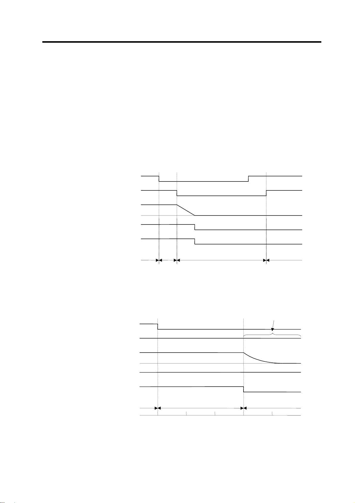
CN23
y
y
(
2. Wiring and Connection
2-9-2 Operation sequences of CN23 external emergency stop function
If only CN23, an external emergency stop, is input when external emergency stop valid is set in the
parameters (the emergency stop is not input in CNC), an "In external emergency stop" (warning EA) will
be detected. At this time, the system itself does not enter an emergency stop status. (There will be no
deceleration control or dynamic brake stop).
If a contactor shutoff command is not issued from the CNC within 30 seconds after the external
emergency stop is input, the power supply unit itself outputs contactor shutoff signal (MC1), and then it
shuts off the contactors, and an external emergency stop error (alarm 55) is detected. If the emergency
stop is input from CNC within 30 seconds, the warning EA replaces the "In CNC emergency stop"
(warning E7). A normal emergency stop status (warning E7) will result if the contactor shutoff command
from the CNC are further input.
Ready ON is possible even if CN23, an external emergency stop has been input when the emergency
stop is canceled, but an external emergency stop error (alarm 55) will occur after 30 seconds.
External emergency stop input
(EMGX)
NC
Main emergency stop input
(EMG)
Motor speed
Contactor control command
Contactor control terminal (MC1)
OFF
ON
OFF
ON
Deceleration control
0
ON
OFF
ON
OFF
Drive unit status display
CN23
External emergency stop input
(EMGX)
NC
Main emergency stop input
(EMG)
Motor speed
Contactor control command
Contactor control terminal
Drive unit status displa
When neither a main emergency stop nor contactor shutoff command is input
dx E7 EA
External emergency stop input sequences
OFF
ON
OFF
ON
0
ON
OFF
MC1)
ON
OFF
dx 55, E7 EA
0 30
Cx → dx
The communication line enters an
emergency stop state by the output
from the servo.
D
namic brake
Time (s)
2 - 28
Page 51

2. Wiring and Connection
2-9-3 Example of emergency stop circuit
(1) Outline of function
The power supply unit's external emergency stop can be validated by wiring to the CN23 connector,
and setting the parameters and rotary switch. If the emergency stop cannot be processed and the
external contractor cannot be shut off (due to a fault) by the CNC unit, the external contactor can be
shut off by the power supply unit instead of the CNC. At this time, the spindle motor will coast and
the servomotor will stop with the dynamic brakes.
EN60204-1 Category 1 can be basically complied with by installing the external emergency stop
switch and contactor.
1. The power supply unit external emergency stop function is a function that
assists the NC emergency stop.
CAUTION
The emergency stop is a signal used to
stop the machine in an emergency. This
is connected to the CNC unit. Wire to the
power supply unit when necessary.
The servo/spindle unit will be decelerated
and controlled by the software according
to the deceleration stop command issued
from the CNC unit.
(2) Example of emergency stop circuit
The diagram on the right shows an
example of the emergency stop circuit
(EN60204-1 Category 0 stop) in which an
off delay timer (TM1) is installed as a
power shutoff method independent from
the NC emergency stop input. The required safety category may be high depending on the machine
and the Safety Standards may not be met. Thus, always pay special attention when selecting the
parts and designing the circuit.
Setting the off delay timer (TM1) time
Set the TM1 operation time so that it functions after it has been confirmed that all axes have
stopped.
If the set time is too short, the spindle motor will coast to a stop.
2. The emergency stop signal input to the CNC side cannot be used as a
substitute for the external emergency stop function (CN23).
3. It will take 30 seconds for the external contactor to function after the
emergency stop is input to CN23. (This time is fixed.)
tm ≥ All axes stop time
External
Emergency
Switch
TM1
R
MC
External
Contactor
RA1
MBR*
GND
AC Reactor
R
GND
CN23
EMG
Power Supply
Unit
CUP
&
ASIC
L11
L21
MC-OFF*
MC1
L1
L2
L3
CN4
NC Unit
CUP
&
ASIC
Servo/Spindle
CN4
L11
L21
P
N
SV1/2
Drive Unit
CUP
&
ASIC
Hardware Emergenc y
CN1A/B
SoftwareEmergency
CN20
MBR*
Motor
Brake
Provide a mechanism that shuts off the power even if the CNC system fails.
Stop Categories in EN60204-1
• Category 0: The power is instantly shut off using machine parts.
• Category 1: The drive section is stopped with the control (hardware/software
or communication network), and then the power is instantly shut
POINT
off using machine parts.
(Caution) Refer to the Standards for details.
Refer to Section 9.2.5.4.2 in EN60204-1: Safety of Machinery
Electrical Equipment of Machines – Part 1.
2 - 29
Page 52

p
2. Wiring and Connection
2-10 Connecting the Grounding Cable
2-10-1 Connecting the Frame Ground (FG)
Each unit has an FG connection terminal. Please connect an earth wire to the main ground of a cabinet
or a machine frame.
Connect the grounding cable from each unit
POINT
directly to the grounding plate. Noise from
other units could result in malfunctions.
MDS-CH-V1/V2/SP
HC-H Series
Servomotor
MDS-CH-CV
SJ-4 Series
Servomotor
CH-AL
Grounding
late
Unit
Unit
Grounding
Grounding
2-10-2 Grounding cable size
Earth wire size should follow the following table.
Type Grounding cable size
MDS-CH-CV Unit Same as TE1 (L1/L2/L3)
MDS-CH-V1/V2/SP[] Unit Same as TE1 (U/V/W)
CH-AL (AC Reactor) 5.5 mm2 (AWG10) or more
2 - 30
Page 53

3. Installation
3-1 Installation of the units .......................................................................................................................3-2
3-1-1 Environmental conditions............................................................................................................3-2
3-1-2 Installation direction and clearance.............................................................................................3-3
3-1-3 Prevention of entering of foreign matter......................................................................................3-3
3-1-4 Panel installation hole work drawings (Panel cut drawings).......................................................3-4
3-1-5 Heating value ..............................................................................................................................3-5
3-1-6 Heat radiation countermeasures................................................................................................. 3-6
3-2 Installation of servomotor/spindle motor............................................................................................ 3-7
3-2-1 Environmental conditions............................................................................................................3-7
3-2-2 Cautions for mounting load (prevention of impact on shaft) ....................................................... 3-8
3-2-3 Installation direction..................................................................................................................... 3-8
3-2-4 Tolerable load of axis..................................................................................................................3-9
3-2-5 Oil and waterproofing measures...............................................................................................3-10
3-2-6 Cable stress ..............................................................................................................................3-12
3-3 Installing the linear servomotor........................................................................................................3-13
3-3-1 Installation environment ............................................................................................................3-13
3-3-2 Installing the linear servomotor ................................................................................................. 3-13
3-3-3 Cooling the linear servomotor................................................................................................... 3-15
3-4 Noise measures ............................................................................................................................... 3-16
3 - 1
Page 54

1. Install the unit on noncombustible material. Direct installation on combustible
material or near combustible materials may lead to fires.
2. Follow the instructions in this manual and install the unit while allowing for the
unit weight.
3. Do not get on top of the units or motor, or place heavy objects on the unit.
Failure to observe this could lead to injuries.
CAUTION
4. Always use the unit within the designated environment conditions.
5. Do not let conductive objects such as screws or metal chips, etc., or
combustible materials such as oil enter the units.
6. Do not block the units intake and outtake ports. Doing so could lead to failure.
7. The units and servomotor are precision devices, so do not drop them or apply
strong impacts to them.
8. Do not install or run units or servomotor that is damaged or missing parts.
9. When storing for a long time, please contact your dealer.
3-1 Installation of the units
3. Installation
1. Always observe the installation directions. Failure to observe this could lead to
CAUTION
faults.
2. Secure the specified distance between the units and panel, or between the
units and other devices. Failure to observe this could lead to faults.
3-1-1 Environmental conditions
Environment Conditions
Ambient temperature 0°C to +55°C (with no freezing)
Ambient humidity 90% RH or less (with no dew condensation)
Storage temperature –15°C to +70°C (with no freezing)
Storage humidity 90% RH or less (with no dew condensation)
Atmosphere Indoors (Where unit is not subject to direct sunlight)
With no corrosive gas, combustible gas, oil mist or dust
Altitude Operation/storage: 1000m or less above sea level
Transportation: 10000m or less above sea level
Vibration Operation/storage: 4.9m/s2 (0.5G) or less
Transportation: 49m/s
Caution) When installing at 1,000m or higher above sea level, the unit's heat dissipation
characteristics will drop as the altitude gets higher.
The upper limit of the ambient temperature drops by 1°C per each 100m increase in
altitude. (The ambient temperature at an altitude of 2000m is 0 to 45°C.).
2
(5G) or less
3 - 2
Page 55

r
r
3. Installation
3-1-2 Installation direction and clearance
Wire each unit in consideration of the maintainability and the heat dissipation, also secure sufficient
space for ventilation.
Do not leave a space between the power supply unit and drive unit when installing.
100mm o
more
Do not leave a space
10mm
or more
Panel
10mm
or more
100mm o
more
The ambient temperature condition for the power supply unit or the drive units is
55°C or less. Because heat can easily accumulate in the upper portion of the
CAUTION
units, give sufficient consideration to heat dissipation when designing the panel.
If required, install a fan in the panel to agitate the heat in the upper portion of the
units.
3-1-3 Prevention of entering of foreign matter
Treat the cabinet with the following items.
• Make sure that the cable inlet is dust and oil proof by using
packing, etc.
• Make sure that the external air does not enter inside by
using head radiating holes, etc.
• Close all clearances.
• Securely install door packing.
• If there is a rear cover, always apply packing.
• Oil will tend to accumulate on the top. Take special
measures such as oil-proofing to the top so that oil does not
enter the cabinet from the screw holds.
• After installing each unit, avoid machining in the periphery. If
cutting chips, etc., stick onto the electronic parts, trouble
may occur.
100mm or
more
70mm
or more
100mm or
more
Wind
passage
Wind
passage
Panel
3 - 3
Page 56

3. Installation
3-1-4 Panel installation hole work drawings (Panel cut drawings)
Prepare a square hole to match the unit width.
2-M5 screw
2-M5 screw2-M5 screw 4-M5 screw
Unit [mm]
60
Square
hole
Unit width: 60mm Unit width: 90mm Unit width: 120mm Unit width: 150mm
360
Square
hole
82
360342
342
Square
hole
360 360342342
341
Square
hole
4-M5 screw
360
180120
Square
hole
4-M5 screw
360341
15
450
180
Square
hole
4-M5
screw
CV SP
Square
hole
142 11252
360
Square
hole
4-M10
screw
480
222
Unit width: 240mm
282
Unit width: 300mm
1. The 75kW spindle drive unit is always installed to the right of the 75kW power
supply unit with no space between. When using the enclosed bar (for L+/L–
connection fitting), leave 34.5mm open between the CV and SP square
holes. Other units cannot be connected together. (Enclosed bar:
C352D058 ... Refer to section 2-5.)
POINT
2. Always install the 37kW to 55kW spindle drive units to the left of the power
supply unit with no space between.
3. A TE2-1 terminal (L+/L–) connection fitting is enclosed with the 45kW and
higher power supply units.
4. Install the power supply unit and drive unit with no space between.
3 - 4
395.5
34.5
282
CV-750 and SP-750
440
Page 57

3. Installation
3-1-5 Heating value
Each heating value is calculated with the following values.
The value for the spindle drive unit includes the continuous rated output, the value for the servo drive
unit includes the rated output, and the value for the power supply unit includes the AC reactor's heating
value.
Heating amount
Inside
panel
[W]
Outside
panel
Type
MDS-CH-
Type
MDS-CH-
CV-37 34 21 SP[]-15 20 50 V1-05 11 25 V2-0505 22 50
CV-55 35 30 SP[]-37 50 54 V1-10 18 41 V2-1005 29 66
CV-75 38 43 SP[]-55 55 88 V1-20 28 76 V2-1010 35 82
CV-110 44 81 SP[]-75 61 121 V1-35 35 115 V2-2010 44 134
CV-150 49 106 SP[]-110 70 170 V1-45 44 164 V2-2020 47 155
CV-185 55 140 SP[]-150 81 231 V1-70 60 258 V2-3510 49 166
CV-220 57 153 SP[]-185 102 353 V1-90 68 302 V2-3520 53 189
CV-260 65 196 SP[]-220 107 380 V1-110 76 327 V2-3535 61 232
CV-300 74 247 SP[]-260 131 513 V1-150 95 455 V2-4520 62 238
CV-370 86 315 SP[]-300 158 668 VI-185 225 575 V2-4535 69 276
CV-450 148 353 SP[]-370 306 797
CV-550 173 428 SP[]-450 355 945
CV-750 235 615 SP[]-550 420 1140
SP[]-750 566 1579
Heating amount
[W]
Inside
Outside
panel
panel
Type
MDS-CH-
Heating
amount [W]
Inside
Outside
panel
panel
Type
MDS-CH-
Heating amount
[W]
Inside
Outside
panel
panel
Design the panel's heating value taking the actual axis operation (load rate) into
consideration. With a general machine tool, the servo drive unit's load rate is
POINT
approx. 50%, so the heating values inside the panel are half the values shown
above. (Excluding the power supply and spindle drive unit.)
(Example 1)
When using MDS-CH-CV-260, MDS-CH-SP[]-185 and MDS-CH-V2-3535
Total heating value = (65 + 196) + (102 + 353) + (61 + 232) = 1009 [W]
Heating value in panel = (65) + (102) + (61 × 0.5) = 197.5 [W]
3 - 5
Page 58

)
(
3. Installation
3-1-6 Heat radiation countermeasures
In order to secure reliability and life, design the temperature in the panel so that the ambient
temperature of each unit is 55°C or less.
If heat accumulates at the top of the unit, etc., install a fan so that the temperature in the panel remains
constant.
Please refer to following method for heat radiation countermeasures.
W ≤ W1
∆T
Calculate total heat radiation of each
mounted unit (W)
Calculate cabinet’s cooling capacity
Comparison of W and W1
Selection of heat exchanger
Collection of internal temperature rise
distribution data
≤10°C
(W1)
Mounting design
Evaluation
∆T>10°C
Improvements
Completion
W>W1
<Hypothetical conditions>
(1) Average temperature in cabinet : T ≤ 55°C
(2) Cabinet peripheral temperature : Ta ≤ 0°C to 45°C
(3) Internal temperature rise value : ∆T = T–Ta
= 10°C
<Supplement>
1) Refer to Specifications Manual, etc. for the heat
generated by each unit.
2) Enclosed cabinet (thin steel plate) cooling capacity
calculation equation
W1 = U × A × ∆T
U: 6W/m
4W/m
A: Effective heat radiation area (m
(Heat dissipation area in panel)
Sections contacting other objects are excluded.
∆T: Internal temperature rise value (10°C)
3) Points of caution for heat radiation countermeasures
when designing mounting state
• Layout of convection in panel
• Collect hot air at suction port in heat exchanger
cabinet.
4) Understanding the temperature rise distribution in the
panel
∆T (average value) ≤ 10°C
∆T
max (maximum value) ≤ 15°C
R (inconsistency ∆T
Evaluate existence of heat spots)
2 ×
°C (with internal agitating fan)
2
× °C (without internal agitating fan)
max – ∆Tmin) ≤ 6°C
Examples of mounting and temperature measurement positions (reference
z Measurement position (example)
max
2
)
Relay, etc.
Flow of
air
Heat
exchanger
Unit
Flow of air
3 - 6
Page 59

3. Installation
3-2 Installation of servomotor/spindle motor
1. Do not hold the cables, axis or detector when transporting the motor. Failure to
observe this could lead to faults or injuries.
2. Securely fix the motor to the machine. Insufficient fixing could lead to the
motor deviating during operation. Failure to observe this could lead to
injuries.
CAUTION
3-2-1 Environmental conditions
Environment Conditions
Ambient temperature 0°C to +40°C (with no freezing)
Ambient humidity 20% to 90%RH or less (with no dew condensation)
Storage temperature –20°C to +65°C (with no freezing)
Storage humidity 20% to 90%RH or less (with no dew condensation)
Atmosphere
Altitude
Vibration
3. When coupling to a servomotor shaft end, do not apply an impact by
hammering, etc. The detector could be damaged.
4. Never touch the rotary sections of the motor during operations. Install a
cover, etc., on the shaft.
5. Do not apply a load exceeding the tolerable load onto the servomotor shaft.
The shaft could break.
6. Do not connect or disconnect any of the connectors while the power is ON.
• Indoors (Where unit is not subject to direct sunlight)
• No corrosive gases, flammable gases, oil mist or dust
Operation/storage: 1000m or less above sea level
Transportation: 10000m or less above sea level
HC-H Series (Servomotor)
SJ Series (Spindle motor) Refer to each specifications.
X: 19.6m/s
Y: 19.6m/s
2
(2G)
2
(2G)
Refer to section "3-3 Installing the linear servomotor" for the linear servomotor's environmental
conditions.
The vibration conditions are as shown below.
200
Servomotor
100
80
X
60
50
40
30
Vibration amplitude
(double-sway width) (µm)
20
Acceleration
1000 2000 30000
Speed (r/min)
Refer to each spindle motor specifications for details on the spindle motor vibration conditions.
Y
3 - 7
Page 60

3. Installation
3-2-2 Cautions for mounting load (prevention of impact on shaft)
<1> When using the servomotor with key way, use the
screw hole at the end of the shaft to mount the pulley
onto the shaft. To install, first place the double-end
stud into the shaft screw holes, contact the coupling
end surface against the washer, and press in as if
tightening with a nut. When the shaft does not have a
key way, use a frictional coupling, etc.
<2> When removing the pulley, use a pulley remover, and
make sure not to apply an impact on the shaft.
<3> Install a protective cover on the rotary sections such
as the pulley installed on the shaft to ensure safety.
<4> The direction of the detector installed on the servomotor cannot be changed.
Servomotor
Pulley
Double-end stud
Nut
Washer
CAUTION
during assembly.
3-2-3 Installation direction
<1> There are no restrictions on the installation direction. Installation in any
direction is possible, but as a standard the motor is installed so that the
motor power line and detector cable cannon plugs (lead-in wires) face
downward. Installation in the standard direction is effective against
dripping. Measure to prevent oil and water must be taken when not
installing in the standard direction. When the motor is not installed in
the standard direction, refer to section "3-2-5 Oil and waterproofing
measures" and take the appropriate measures.
The brake plates may make a sliding sound when a servomotor with
magnetic brake is installed with the shaft facing upward, but this is not
a fault.
Never hammer the end of the shaft
Up
Down
Standard installation
direction
3 - 8
Page 61

3. Installation
3-2-4 Tolerable load of axis
There is a limit to the load that can be applied on the motor shaft. Make sure that the load applied on the
radial direction and thrust direction, when mounted on the machine, is below the tolerable values given
below. These loads also affect the motor output torque, so consider them when designing the machine.
Servomotor
HC-H52T, 53T, 102T, 103T, 152T, 153T
(Taper shaft)
HC-H52S, 53S, 102S, 103S, 152S, 153S
(Straight shaft)
HC-H202S, 203S, 352S, 353S, 452S, 453S
(Straight shaft)
Tolerable radial load Tolerable thrust load
392N (L=52.7) 490N
980N (L=52.7) 490N
1500N (L=52.7) 490N
HC-H702S, 703S (Straight shaft) 1300N (L=52.7) 590N
HC-H902S, 903S (Straight shaft) 2500N (L=52.7) 1100N
HC-H1102S, 1103S (Straight shaft) 2700N (L=52.7) 1500N
Caution: The symbols in the table follow the drawing below.
During operation
L
Radial load
Thrust load
L : Length from flange installation surface to center of load weight [mm]
1. Use a flexible coupling when connecting with a ball screw, etc., and keep the
shaft core deviation to below the tolerable radial load of the shaft.
2. When directly installing the gear on the motor shaft, the radial load increases
as the diameter of the gear decreases. This should be carefully considered
when designing the machine.
3. When directly installing the pulley on the motor shaft, carefully consider so
CAUTION
that the radial load (double the tension) generated from the timing belt
tension is less than the values shown in the table above.
4. In machines where thrust loads such as a worm gear are applied, carefully
consider providing separate bearings, etc., on the machine side so that loads
exceeding the tolerable thrust loads are not applied to the motor.
5. Do not use a rigid coupling as an excessive bending load will be applied on
the shaft and could cause the shaft to break.
3 - 9
Page 62

3. Installation
3-2-5 Oil and waterproofing measures
<1> A format based on IEC Standards (IP types) is displayed as the motor
protective format (refer to "10-2-1 Specifications list."). However, these
Standards are short-term performance specifications. They do not
guarantee continuous environmental protection characteristics.
Measures such as covers, etc., must be provided if there is any
possibility that oil or water will fall on the motor, or the motor will be
constantly wet and permeated by water. Note that the motor’s IP-type
is not indicated as corrosion-resistant.
<2> When a gear box is installed on the servomotor, make sure that the oil level height from the center
of the shaft is higher than the values given below. Open a breathing hole on the gear box so that the
inner pressure does not rise.
Servomotor Oil level (mm)
HC-H52, 53, 102, 103, 152, 153 20
HC-H202, 203, 352, 353 25
Oil level
HC-H452, 453, 702, 703 25
HC-H902, 903, 1102, 1103 30
<3> When installing the servomotor horizontally, set the power cable and detector cable to face
downward.
When installi ng vertically or on an inclination, provide a cable trap.
Gear
Lip
V-ring
Oil or water
Servomotor
Servomotor
Cable trap
1. The servomotors, including those having IP65 and IP67 specifications, do not
have a completely waterproof (oil-proof) structure. Do not allow oil or water to
constantly contact the motor, enter the motor, or accumulate on the motor. Oil
can also enter the motor through cutting chip accumulation, so be careful of
CAUTION
this also.
2. When the motor is installed facing upwards, take measures on the machine
side so that gear oil, etc., does not flow onto the motor shaft.
3. Do not remove the detector from the motor. (The detector installation screw is
treated for sealing.)
3 - 10
Page 63

r
r
3. Installation
<4> Do not use the unit with the cable submerged in oil or
water.
(Refer to right drawing.)
<5> Make sure that oil and water do not flow along the cable
into the motor or detector. (Refer to right drawing.)
<6> When installing on the top of the shaft end, make sure
that oil from the gear box, etc., does not enter the
servomotor. The servomotor does not have a
waterproof structure.
Cover
Servomotor
Oil or wa t e r pool
<Fault> Capillary tube Phenomenon
Cover
Servomotor
<Fault> Res pi r at i on
Gear
Lubricating oil
Se
vomoto
3 - 11
Page 64

A
3. Installation
3-2-6 Cable stress
<1> Sufficiently consider the cable clamping method so that bending stress and the stress from the
cable's own weight is not applied on the cable connection part.
<2> In applications where the servomotor moves, make sure that excessive stress is not applied on the
cable.
If the detector cable and servomotor wiring are stored in a cable bear and the servomotor moves,
make sure that the cable bending part is within the range of the optional detector cable.
Fix the detector cable and power cable enclosed with the servomotor.
<3> Make sure that the cable sheathes will not be cut by sharp cutting chips, worn, or stepped on by
workers or vehicles.
<4> The bending life of the detector cable is as shown below. Regard this with a slight allowance. If the
servomotor/spindle motor is installed on a machine that moves, make the bending radius as large
as possible.
8
110
7
510
7
210
7
110
)
s
e
m
i
t
(
s
d
n
e
b
f
o
.
o
N
6
510
6
210
6
110
5
510
5
210
5
110
4
4 7 10 20 40 70 100 200
510
4
310
14B2343
Bending radius(mm)
TS-91026
Detector cable bending life
Note: The values in this graph are calculated values and are not guaranteed.
<5> The oil resistance characteristics are given below. Note that these values are not guaranteed for all
types of oils.
Item Characteristics
Tensile strength 65% or more of value before immersion in oil
Elongation 65% or more of value before immersion in oil
70°C for four hours (JIS C 2320 Class 1 No. 2
insulation oil)
Oil
resistance
Sheath
Oil resistance conditions
<6> The detector cable sheath is made of flame retardant PVC.
3 - 12
Page 65

3-3 Installing the linear servomotor
1. Securely fix the linear servomotor onto the machine. Incomplete fixing could
cause the servomotor to come off during operation, and lead to injuries.
2. The connectors, cooling ports, etc., cannot be repaired or replaced. The
entire servomotor must be replaced, so take special care when handling.
3. Use nonmagnetic tools during installation.
4. An attraction force is generated in the magnetic body by the secondary side
permanent magnet. Take care not to catch fingers or hands. Take special
CAUTION
3-3-1 Installation environment
care when installing the primary side after the secondary side.
5. Install the counterbalance for the vertical axis and the holding brakes on the
machine side. The balance weight cannot track at 9.8m/s
pneumatic counterbalance, etc., having high trackability.
6. Always install an electrical and mechanical stopper at the stroke end.
7. Take measure to prevent metal cutting chips from being attracted to the
secondary side permanent magnet.
8. Oil-proofing and dust-proofing measures must be provided for the linear
scale.
3. Installation
2
or more, so use a
Environment Conditions
Ambient temperature 0°C to 40°C (with no freezing)
Ambient humidity 80% RH or less (with no dew condensation)
Storage temperature –15°C to 50°C (with no freezing)
Storage humidity 90% RH or less (with no dew condensation)
Atmosphere
Indoors (Where unit is not subject to direct sunlight)
With no corrosive gas, flammable gas or dust
Vibration 4.9m/s2 or less
3-3-2 Installing the linear servomotor
(1) Installing the primary side
Dimensions for tie-in with secondary side
Center of primary side
0.5[mm] or less
0.1 A
0.1
0.1[mm]
±
H
A
0.1
Center of secondary side
Caution: H dimensions = (primary side height dimensions) + (secondary side height dimensions)
+ (clearance length: 0.5[mm]).
3 - 13
Page 66

3. Installation
Example of installation procedures
An example of the installation procedures is shown below.
Step 2
Install the primary side on the position where there is no secondary side
Step 1
Install the secondary side (1 part)
Step 4
Install the remaining secondary side
Step 3
Move over to the secondary side where the
primary side is installed.
1. Installing the primary side on the position where there is no secondary side,
as shown above, is recommended to avoid risks posed by the attraction force
of the permanent magnet between the primary side and secondary side.
2. If the primary side must be installed over the secondary side, use a material
CAUTION
handling device, such as a crane, which can sufficiently withstand the load
such as the attraction force.
3. Note that an attraction force will be generated even after the primary side has
been installed and is moved over to the secondary side.
1. Keep the moving sections (primary side) as light as possible, and the base
section (secondary side) as heavy and rigid as possible.
2. Make the machine's rigidity as high as possible.
3. Securely fix the base section (secondary side) onto the foundation with
anchor bolts.
4. Keep the primary resonance frequency of the entire machine as high as
POINT
possible. (Should be 200Hz or more.) Install the servomotor so that the thrust
is applied on the center of the moving sections. If the force is not applied on
the center of the moving parts, a moment will be generated.
5. Use an effective cooling method such as circulated cooling oil.
6. Select a motor capacity that matches the working conditions.
7. Create a mechanism that can withstand high speeds and high acceleration/
deceleration.
3 - 14
Page 67

3. Installation
(2) Installing the secondary side
Direction
When using multiple secondary sides, lay the units out so that the nameplates on the products all
face the same direction in order to maintain the pole arrangement.
Rating nameplate
Procedures
Install with the following procedure to eliminate clearances between the secondary sides.
Step 2.
Fix with bolt.
Step 1.
Press against.
Secondary side used as
installation reference
1. Use nonmagnetic tools when installing the secondary side.
2. When placing the secondary side onto the installation surface, use the
screws on the product, and suspend with eye bolts, etc.
CAUTION
3. If the secondary side is already installed and another secondary side is being
added, place the secondary side away from the side already installed, and
then slide the additional secondary side to the specific position.
3-3-3 Cooling the linear servomotor
(1) A cooling pipe is embedded on the primary side of the linear servomotor. Flow at least 5 liters of
cooling oil per minute.
(2) When using with natural cooling, the continuous rating will be dropped to 50% compared to when
using cooling oil.
3 - 15
Page 68

p
r
p
g
3. Installation
3-4 Noise measures
Noise includes "propagation noise" generated from the power supply or relay, etc., and propagated
along a cable causing the power supply unit or drive unit to malfunction, and "radiated noise"
propagated through air from a peripheral device, etc., and causing the power supply unit or drive unit to
malfunction.
Always implement these noise measures to prevent the peripheral devices and unit from malfunctioning.
The measures differ according to the noise propagation path, so refer to the following explanation and
take appropriate measures.
(1) Mandatory noise measures
• Accurately ground all of the cables connected to this unit and requiring shielding treatment with
clamp fittings. (The communication cable connected to the NC can be grounded with one clamp
fitting on the NC side. However, the communication cables connected between each drive unit
are not required to ground with the clamp fitting.)
Make sure that the detector cable or the signal wire (FG wire) for the communication cable to the
NC is accurately grounded to the connector shell section.
• Do not lay the "drive unit input/output power wire" and "signal wires" bundled in a parallel state.
Always separate these wires.
• Use one-point grounding for the drive unit and motor.
(Refer to section "2-10 Wiring the grounding cable.)
• Accurately ground the AC reactor using the FG terminal on the terminal block in addition to the PE
terminal on the body.
• Install a surge killer on devices (magnetic contactor, relay, etc.) that generate high levels of noise.
• Accurately ground all of the detector cables with clamp fittings.
(The FG wire to the connector shell must also be grounded.)
• Always take the measures given in "Appendix 2 EMC Installation Guidelines" for the European
EMC Directives.
(2) Propagation noise measures
Always take the following measures when noise generating devices are installed near this unit.
• Install a power line filter in the stage before the power supply unit.
• Install a ferrite core on the signal wire.
• Wire the spindle PLG detector cable away from other wires.
(3) Measures against radiated noise
The types of propagation paths of the noise and the noise measures for each propagation path are
shown below.
Noise generated
from drive unit
Airborne
propagation noise
Magnetic
induction noise
Static induction
noise
Cable propagation
noise
and <5>
Noise directly radiated
from drive unit
Noise radiated from
ower line
Noise radiated from
servomotor/spindle
moto
Noise propagated over
ower line
Noise lead in from
grounding wire by
leaka
e current
Path <1>
Path <2>Path <4>
Path <3>Path <6>
Path <7>
Path <8>
3 - 16
Page 69

Example) Drive system
3. Installation
<5>
<7>
<2>
<7>
<2>
propagation
<1> <2> <3>
<4> <5> <6>
Noise
path
<7>
<8>
Instrument
Receiver
<1>
<3>
Servomotor
Spindle motor
Drive
unit
<6>
<4>
M
Sensor
power
supply
Sensor
<8>
Measures
When devices such as instrument, receiver or sensor, which handle minute signals
and are easily affected by noise, or the signal wire of these devices, are stored in
the same panel as the drive units and the wiring is close, the device could
malfunction due to airborne propagation of the noise. In this case, take the following
measures.
(1) Install devices easily affected as far away from the drive units as possible.
(2) Lay devices easily affected as far away from the signal wire of the drive unit as
possible.
(3) Do not lay the signal wire and power line in parallel or in a bundled state.
(4) Insert a line noise filter on the input/output wire to suppress noise radiated from
the wires.
(5) Use a shield wire for the signal wire and power line, or place in separate metal
ducts.
If the signal wire is laid in parallel to the power line, or if it is bundled with the power
line, the noise could be propagated to the signal wire and cause malfunction
because of the magnetic induction noise or static induction noise. In this case, take
the following measures.
(1) Install devices easily affected as far away from the drive unit as possible.
(2) Lay devices easily affected as far away from the signal wire of the drive unit as
possible.
(3) Do not lay the signal wire and power line in parallel or in a bundled state.
(4) Use a shield wire for the signal wire and power line, or place in separate metal
ducts.
If the power supply for the peripheral devices is connected to the power supply in
the same system as the drive units, the noise generated from the power supply unit
could back flow over the power line and cause the devices to malfunction. In this
case, take the following measures.
• Install a power line filter on the power supply unit's power line.
If a closed loop is created by the peripheral device and drive unit grounding wire, the
noise current could be fed back causing the device to malfunction. In this case,
change the device grounding methods and the grounding place.
3 - 17
Page 70

4. Setup
4-1 Initial setup........................................................................................................................................4-2
4-1-1 Setting the rotary switch ............................................................................................................ 4-2
4-1-2 Transition of LED display after power is turned ON.................................................................. 4-3
4-2 Servo drive unit initial parameter settings ........................................................................................4-4
4-2-1 List of servo parameters ............................................................................................................4-4
4-2-2 Limitations to electronic gear setting value.............................................................................. 4-19
4-2-3 Setting excessive detection error width...................................................................................4-19
4-2-4 Setting motor and detector model............................................................................................4-20
4-2-5 Setting servo specifications..................................................................................................... 4-21
4-2-6 Initial setup of the linear servo system.....................................................................................4-22
4-2-7 Standard parameter list according to motor ............................................................................4-31
4-3 Spindle drive unit initial parameter settings....................................................................................4-33
4-3-1 List of spindle parameters........................................................................................................4-33
4-3-2 Details of bit-corresponding parameters..................................................................................4-50
4-3-3 Setting spindle drive unit and motor model .............................................................................4-54
4-3-4 Spindle specification parameters screen.................................................................................4-55
4-3-5 Spindle control signals.............................................................................................................4-58
4 - 1
Page 71

4. Setup
4-1 Initial setup
Check the combination of the drive unit and motor connected.
The linear servomotor can be driven with the MDS-CH-V1 Series software version "BND-583W000-B0"
and higher.
4-1-1 Setting the rotary switch
Before turning on the power, the axis No. must be set with the rotary switch. The rotary switch settings
will be validated when the units are turned ON.
(1) Setting the power supply unit
789
6
A
B
5
4
C
3
D
2
E
1
F
0
(2) Setting the servo/spindle drive unit
8
8
9
9
7
7
A
6
5
4
3
2
1
A
6
B
B
5
C
C
4
D
D
3
E
E
2
F
F
1
0
0
When MDS-CH-V2 Series are used
SW1 MDS-CH-CV setting
0
1 With no contactor
2
3
4
5 With no contactor
With contactor
(melting detection)
Setting prohibited
With contactor
(melting detection)
External emergency
stop (Not used CN23)
External emergency
stop (Used CN23)
6
7
8
9
A
B
Setting prohibited
C
D
E
F
Rotary switch
setting
0 1st axis
1 2nd axis
2 3rd axis
3 4th axis
4 5th axis
5 6th axis
6 7th axis
7
8
9
A
B
C
D
E
F Axis not used
Set axis No.
Not usable
When an axis that is not used is selected, that axis will not be controlled when
the power is turned ON, and "Ab" will remain displayed on the LED. If the power
POINT
of the axis not in use is disconnected, the NC system's emergency stop cannot
be released.
4 - 2
Page 72

4. Setup
4-1-2 Transition of LED display after power is turned ON
When CNC, each drive unit and the power supply unit power have been turned ON, each unit will
automatically execute self-diagnosis and initial settings for operation, etc. The LEDs on the front of the
units will change as shown below according to the progression of these processes.
If an alarm occurs, the alarm No. will appear on the LEDs. Refer to "Chapter 8 Troubleshooting" for
details on the alarm displays.
Waiting for NC
power start up
NC power ON
Drive units
LED display
Drive unit initialization complete
Waiting for NC power start up
NC power ON
Executing initial
communication with NC
Power supply unit
LED display
NC power
ON
Executing initial communication
with NC
A : Initializing
b : Ready OFF, in emergency stop
c : Ready ON/servo OFF
Emergency stop state
The LED will alternate between
F# → E7 → not lit.
(# is the set axis No.)
Servo ON state Servo OFF sate
NC power OFF
Repeats lighting and going out.
(1st axis in the display example)
Servo ON state
Emergency stop state
4 - 3
Page 73

4. Setup
4-2 Servo drive unit initial parameter settings
Refer to each CNC instruction manual for details on the operation methods and system specification
parameter settings.
4-2-1 List of servo parameters
No. Abbrev. Parameter name Explanation
SV001 PC1*
SV002 PC2*
SV003 PGN1 Position loop gain 1
SV004 PGN2 Position loop gain 2
SV005 VGN1 Speed loop gain 1
SV006 VGN2 Speed loop gain 2
SV007 VIL
SV008 VIA
Motor side gear
ratio
Machine side gear
ratio
Speed loop delay
compensation
Speed loop lead
compensation
Set the motor side and machine side gear ratio.
For the rotary axis, set the total deceleration (acceleration) ratio.
Even if the gear ratio is within the setting range, the electronic gears may
overflow and cause an alarm.
Set the position loop gain. The standard setting is “33”.
The higher the setting value is, the more precisely the command can be
followed and the shorter the positioning time gets, however, note that a
bigger shock is applied to the machine during acceleration/deceleration.
When using the SHG control, also set SV004 (PGN2) and SV057 (SHGC).
(If “201” or bigger is set, the SHG control cannot be used.)
When using the SHG control, also set SV003 (PGN1) and SV057 (SHGC).
When not using the SHG control, set to “0”.
Set the speed loop gain.
Set this according to the load inertia size.
The higher the setting value is, the more accurate the control will be,
however, vibration tends to occur.
If vibration occurs, adjust by lowering by 20 to 30%.
The value should be determined to be 70 to 80% of the value at the time
when the vibration stops.
If the noise is bothersome at high speed
during rapid traverse, etc, lower the speed
loop gain.
As in the right figure, set the speed loop
gain of the speed 1.2 times as fast as the
motor’s rated speed, and use this with
SV029 (VCS).
When not using, set to “0”.
Set this when the limit cycle occurs in the full-closed loop, or overshooting
occurs in positioning.
Select the control method with SV027 (SSF1)/bit1, 0 (vcnt).
Normally, use “Changeover type 2”.
When you set this parameter, make sure to set the torque offset (SV032
(TOF)). When not using, set to “0”.
No changeover
When SV027 (SSF1)/ bit1, 0 (vcnt)=00
The delay compensation control is always valid.
Changeover type 1
When SV027 (SSF1)/ bit1, 0 (vcnt)=01
The delay compensation control works when the command from the NC
is “0”.
Overshooting that occurs during pulse feeding can be suppressed.
Changeover type 2
When SV027 (SSF1)/ bit1, 0 (vcnt)=10
The delay compensation control works when the command from the NC
is “0” and the position droop is “0”. Overshooting or the limit cycle that
occurs during pulse feeding or positioning can be suppressed.
Set the gain of the speed loop integration control.
The standard setting is “1364”. During the SHG control, the standard
setting is “1900”. Adjust the value by increasing/decreasing it by about
100 at a time.
Raise this value to improve contour tracking precision in high-speed
cutting. Lower this value when the position droop vibrates (10 to 20Hz).
VGN1
VGN2
VCS VLMT
0
(Rated speed*1.2)
Parameters with an asterisk * in the abbreviation, such as PC1*, are validated with the NC power is turned ON again.
Setting
range (Unit)
1 to 32767
1 to 32767
1 to 200
(rad/s)
0 to 999
(rad/s)
1 to 10000
-1000 to
0 to 32767
1 to 9999
1000
4 - 4
Page 74

4. Setup
No. Abbrev. Parameter name Explanation
SV009 IQA
SV010 IDA
SV011 IQG
SV012 IDG
SV013 ILMT Current limit value
SV014 ILMTsp
SV015 FFC
SV016 LMC1
Current loop q axis
lead compensation
Current loop d axis
lead compensation
Current loop q axis
gain
Current loop d axis
gain
Current limit value in
special control
Acceleration rate
feed forward gain
Lost motion
compensation 1
Set the gain of current loop.
As this setting is determined by the motor’s electrical characteristics, the
setting is fixed for each type of motor.
Set the standard values for all the parameters depending on each motor
type.
Set the normal current (torque) limit value. (Limit values for both + and direction.)
When the value is “500” (a standard setting), the maximum torque is
determined by the specification of the motor.
Set the current (torque) limit value in a special control (initial absolute
position setting, stopper control, etc). (Limit values for both of the + and directions.)
Set to “500” when not using.
When a relative error in the synchronous control is large, apply this
parameter to the axis that is delaying. The standard setting value is “0”.
For the SHG control, set to “100”.
To adjust a relative error in acceleration/deceleration, increase the value by
50 to 100 at a time.
Set this when the protrusion (that occurs due to the non-sensitive band by
friction, torsion, backlash, etc) at quadrant change is too large.
This compensates the torque at quadrant change.
This is valid only when the lost motion compensation (SV027 (SSF1/lmc))
is selected.
Type 1: When SV027 (SSF1)/bit9, 8 (lmc)=01
Set the compensation amount based on the motor torque before the
quadrant change.
The standard setting is “100”. Setting to “0” means the compensation
amount is zero.
Normally, use Type 2.
Type 2: When SV027 (SSF1)/bit9, 8 (lmc)=10
Set the compensation amount based on the stall (rated) current of the
motor.
The standard setting is double of the friction torque. Setting to “0”
means the compensation amount is zero.
When you wish different compensation amount depending on the direction
When SV041 (LMC2) is “0”, compensate with the value of SV016
(LMC1) in both of the + and -directions.
If you wish to change the compensation amount depending on the
command direction, set this and SV041 (LMC2). (SV016: + direction,
SV041: - direction. However, the directions may be opposite
depending on other settings.)
When “-1” is set, the compensation won’t be performed in the direction of
the command.
Parameters with an asterisk * in the abbreviation, such as PC1*, are validated with the NC power is turned ON again.
Setting
range (Unit)
1 to 20480
1 to 4096
In case of
MDS-B-Vx4,
1 to 8192
0 to 999
(Stall
[rated]
current %)
0 to 999
(Stall
[rated]
current %)
0 to 999
(%)
-1 to 200
(%)
-1 to 100
(Stall
[rated]
current %)
4 - 5
Page 75

4. Setup
No. Abbrev. Parameter name Explanation
Setting
range (Unit)
FEDCB A 98765 4 3 2 10
spm drvall drvup mpt3 mp abs vdir fdir vfb seqh dfbx fdir2
bit Meaning when “0” is set Meaning when “1” is set
0 fdir2 Speed feedback forward polarity Speed feedback reverse polarity
1 dfbx Dual feedback control stop Dual feedback control start
2
4 fdir Position feedback forward polarity Position feedback reverse polarity
5
SV017 SPEC*
8 mp MP scale 360P (2mm pitch) MP scale 720P (1mm pitch)
A
B
C
D
E
F
3vfb
Servo specification
selection
9
6
7 abs Incremental control Absolute position control
Speed feedback filter stop Speed feedback filter stop
MP scale ABS detection NC
mpt3
control
2 : Rotary servomotor
spm
8 : Linear servomotor
All other setting values are prohibited
(2250Hz)
MP scale ABS detection
automatic (Standard swetting)
HEX setting
(Note 1) Set to “0” for bits with no particular description.
SV018 PIT*
Parameters with an asterisk * in the abbreviation, such as PC1*, are validated with the NC power is turned ON again.
Ball screw pitch Set the ball screw pitch. Set to “360” for the rotary axis.
Pole pitch Set the pole pitch when using the linear servomotor.
1 to 32767
(mm/rev)
4 - 6
Page 76

4. Setup
No. Abbrev. Parameter name Explanation
In the case of the semi-closed loop control
Set the same value as SV020 (RNG2). (Refer to the explanation of
SV020.)
In the case of the full-closed loop control
Set the number of pulses per ball screw pitch.
Detector model name Resolution SV019 setting
OHE25K- E T , O HA25K - E T 100,000 (p/rev) 100
OSE104-ET,OSA104-ET 100,000 (p/rev) 100
OSE105-ET,OSA105-ET 1,000,000 (p/rev) 1000
RCN723 (Heidenhain) 8,000,000 (p/rev) 8000
Relative position
detection scale
AT41 (Mitsutoyo) 1 (m/p)
FME type, FLE type
(Futaba)
MP type (Mitsubishi
SV019 RNG1*
Position detector
resolution
Heavy Industries)
AT342 (Mitsutoyo) 0.5 (m/p)
AT343 (Mitsutoyo) 0.05 (m/p)
AT543 (Mitsutoyo) 0.05 (m/p)
LC191M (Heidenhain)
LC491M (Heidenhain)
MDS-B-HR Analog cycle/500
For linear servomotor control
Set the number of pulses (K pulses) per pole pitch.
(Set the same value for SV020: RNG2.)
AT342 LC191M HR + relative position detector HR + AT342
120 600 or 1200 PIT/Resolution (m) 1500
Note)
The above value applies for the linear servomotor with 60mm
pole pitch.
Set the number of pulses per one revolution of the motor side detector.
Detector model name SV020 setting
SV020 RNG2*
Speed detector
resolution
OSE104, OSA104 100
OSE105, OSA105 1000
Set the same value as SV019: RNG1 when using linear servomotor
control.
SV021 OLT
SV022 OLL
Overload detection
time constant
Overload detection
level
Set the detection time constant of Overload 1 (Alarm 50).
Set to “60” as a standard. (For machine tool builder adjustment.)
Set the current detection level of Overload 1 (Alarm 50) in respect to the
stall (rated) current.
Set to “150” as a standard. (For machine tool builder adjustment.)
Set the excessive error detection width when servo ON.
SV023 OD1
Excessive error
detection width
<Standard
setting value> OD1=OD2=
during servo ON
When “0” is set, the excessive error detection will not be performed.
Set the in-position detection width.
SV024 INP
In-position
detection width
Set the accuracy required for the machine.
The lower the setting is, the higher the positioning accuracy gets, however,
the cycle time (setting time) becomes longer. The standard setting is “50”.
Parameters with an asterisk * in the abbreviation, such as PC1*, are validated with the NC power is turned ON again.
Refer to specification
manual for each detector
Refer to specification
manual for each detector
Refer to specification
manual for each detector
Refer to specification
manual for each detector.
Refer to specification
manual for each detector.
Rapid traverse rate
(mm/min)
60*PGN1
PIT/Resolution
(m)
The same as
SV018 (PIT)
PIT/Resolution
(m)
PIT/Resolution
(m)
Twice as big as
SV018 (PIT)
20 times as big
as SV018 (PIT)
PIT/Resolution
(m)
PIT/Resolution
(m)
PIT/Resolution
(m)
PIT/Resolution
(m)
/2 (mm)
Setting range
(Unit)
1 to 9999
(kp/rev)
1 to 9999
(kp/pit)
1 to 9999
(kp/pit)
1 to 9999
(kp/rev)
1 to 999
(s)
110 to 500
(Stall [rated]
current %)
0 to 32767
(mm)
0 to 32767
(m)
4 - 7
Page 77

4. Setup
No. Abbrev. Parameter name Explanation
HEX setting
FEDCBA98765 4 3 2 10
pen ent mtyp
bit Explanation
0 Set the motor type. Set this along with SV017 (SPEC)/spm.
1 1) When SV017/spm=2 (Rotary servomotor)
2 Setting 0x 1x 2x 3x 4x 5x 6x 7x
3 x0
4
5 x2
6 x3
7 x4
x5
x6
x7
x8
x9
xA
xB
xC
xD
xE
xF
Setting 8x 9x Ax Bx Cx Dx Ex Fx
x0 HC-H52 HC-H53
x1 HC-H102 HC-H103
x2 HC-H152 HC-H153
SV025 MTYP* Motor/Detector type
x5 HC-H452 HC-H453
x6 HC-H702 HC-H703
x9 HC-H1502
xA
xB
xC
xD
xE
xF
2) When SV017/spm=8 (Linear servomotor)
Setting 0x 1x 2x 3x 4x 5x 6x 7x
x0
x1
x2
x3
x4
x5
x6
x7
x8
x9
xA
xB
xC
xD
xE
xF
Parameters with an asterisk * in the abbreviation, such as PC1*, are validated with the NC power is turned ON again.
x3 HC-H202 HC-H203
x7 HC-H902 HC-H903
mtyp
x1
x4 HC-H352 HC-H353
x8 HC-H1102 HC-H1103
LM-NP5G-60P
(Natural cooling)
LM-NP5G-60P
(Oil cooled)
4 - 8
Page 78

4. Setup
No. Abbrev. Parameter name Explanation
HEX setting
8
9
A
B
C
D 0 0 OSE104
E
F 2 2 OSE105, OSA105
3 3
4 Setting impossible OHE25K-ET, OSE104-ET
5 Setting impossible OHA25K-ET, OSA104-ET
6 Setting impossible
8 Setting impossible
SV025 MTYP* Motor/Detector type 9 Setting impossible
A A
B Setting impossible
C -
C
D - For closed-loop speed control
D A
D D
D E
E Setting impossible
F Setting impossible
Set the excessive error detection width when servo ON.
For the standard setting, refer to the explanation of SV023 (OD1).
When “0” is set, the excessive error detection will not be performed.
SV026 OD2
Excessive error
detection width
during servo OFF
Parameters with an asterisk * in the abbreviation, such as PC1*, are validated with the NC power is turned ON again.
Set the detector type.
Set the position detector type for “pen”, and the speed detector type
ent
for “ent”. In the case of the semi-closed loop control, set the same
value for “pen” and “ent”.
pen
setting
pen
1 1 OSA104
ent setting Detector model name
OSE105-ET, OSA105-ET, RCN723
7 Setting impossible
C
(Current
synchronization)
(Heidenhain)
Relative position detection scale, MP type
(Mitsubishi Heavy Industries)
AT41 (Mitsutoyo), FME type, FLE type
(Futaba)
AT342, AT343, AT543 (Mitsutoyo),
LC191M/491M (Heidenhain), MDS-B-HR
For semi-closed speed synchronization
setting
The setting of the slave axis in the speed/current
synchronization control.
When the master axis is the semi-closed control.
Settings for slave axis in 2-scale 2-linear
servomotor system (Using CN3 connector)
The setting of the slave axis in the speed/ current
synchronization control.
When the master axis is the full-closed control.
For linear servomotor current synchronization
For V2 closed-loop current synchronization
control
Setting range
(Unit)
0 to 32767
(mm)
4 - 9
Page 79

4. Setup
No. Abbrev. Parameter name Explanation
HEX setting
F E D C B A 9 8 7 6 5 4 3 2 1 0
aflt zrn2 afse ovs lmc omr zrn3 vfct vcnt
bit Meaning when “0” is set Meaning when “1” is set
0
1
2
3
4
Set the execution changeover type of the speed loop delay compensation.
vcnt
00: Delay compensation changeover invalid
01: Delay compensation changeover type 1
Set the number of compensation pulses of the jitter compensation.
vfct
00: Jitter compensation invalid
5
01: Jitter compensation 1 pulse
10: Jitter compensation 2 pulses
11: Jitter compensation 3 pulses
10: Delay compensation type 2
11: Setting prohibited
SV027 SSF1 Servo function 6 zrn3 ABS scale: Set to “1” in using AT342, AT343, AT543, LC191M/491M.
selection 1 7 omr Machine side compe nsation invalid Machine side compensat ion valid
8
A
C 00: Adoptive filter sensitivity standard
D
E zrn2 Set to “1”.
F aflt Adoptive filter stop Adoptive filter start
B
(Note) Set to "0" for bits with no particular description.
Set the compensation amount with SV016 (LMC1) and SV041 (LMC2).
lmc
00: Lost motion compensation stop
9
01: Lost motion compensation type 1
Set the compensation amount with SV031 (OVS1) and SV042 (OVS2).
ovs
00: Overshooting compensation stop
01: Overshooting compensation type 1
afse
11: Adoptive filter sensitivity increase (Set 2bits at a time)
10: Lost motion compensation type 2
11: Setting prohibited
10: Overshooting compensation type 2
11: Setting prohibited
Set the pole shift amount for the linear servomotor.
SV028 MSFT Pole shift amount
This is not used for the rotary servomotor.
Set to “0”.
If the noise is bothersome at high speed during rapid traverse, etc, lower
the speed loop gain.
Set the speed at which the speed loop gain changes, and use this with
SV006 (VGN2).
When not using, set to “0”.
SV029 VCS
Speed at the change
of speed loop gain
The setting unit differs for the linear servo, but the function is the same as
that explained here.
Abbrev. Parameter name Explanation
Setting range
(Unit)
When 100% is set, the voltage equivalent to the logical
SV030
IVC
Voltage dead time
compensation
non-energized time will be compensated.
When “0” is set, a 100% compensation will be performed.
Adjust in increments of 10% from the default value 100%.
If increased too much, vibration or vibration noise may be
0 to 255
(%)
generated.
Parameters with an asterisk * in the abbreviation, such as PC1*, are validated with the NC power is turned ON again.
Setting range
-32768 to
32767 (µm)
0 to 9999
0 to 9999
(Unit)
(r/min)
(mm/s)
0 to 255
4 - 10
Page 80

4. Setup
No. Abbrev. Parameter name Explanation
Set this if overshooting occurs during positioning. This compensates the
motor torque during positioning.
This is valid only when the overshooting compensation SV027 (SSF1/ovs)
is selected.
Type 1: When SV027 (SSF1)/ bitB, A (ovs)=01
Set the compensation amount based on the motor’s stall current.
This compensates overshooting that occurs during pulse feeding.
Normally, use Type 2.
Type 2: When SV027 (SSF1)/ bitB, A (ovs)=10
Set the compensation amount based on the motor’s stall current.
Increase by 1% and determine the amount that overshooting doesn’t
occur.
SV031 OVS1
SV032 TOF Torque offset
HEX setting
FEDCBA98765 4 3 2 10
dos nfd2 nf3 nfd1 zck
bit Meaning when “0” is set Meaning when “1” is set
0 zck Z phase check valid (Alarm 42) Z phase check invalid
1 Set the filter depth for Notch filter 1 (SV038).
2 nfd1 Value 000 001 010 011 100 101 110 111
3
4 nf3 Notch filter 3 stop Notch filter 3 start (1125Hz)
5 Set the operation frequency of Notch filter 2 (SV046).
6 nfd2 Value 000 001 010 011 100 101 110 111
SV033 SSF2
8
9
A
B
C
D
E
F
Parameters with an asterisk * in the abbreviation, such as PC1*, are validated with the NC power is turned ON again.
Overshooting
compensation 1
Servo function
selection 2
In Type 2, compensation during the feed forward control during circular
cutting won’t be performed.
Type 3: When SV027 (SSF1)/ bitB, A (ovs)=11
Use this to perform the overshooting compensation during circular
cutting or the feed forward control. The setting method is the same in
Type 2.
When you wish different compensation amount depending on the direction
When SV042 (OVS2) is “0”, compensate with the value of SV031
(OVS1) in both of the + and -directions.
If you wish to change the compensation amount depending on the
command direction, set this and SV042 (OVS2). (SV031: + direction,
SV042: - direction. However, the directions may be opposite
depending on other settings.)
When “-1” is set, the compensation won’t be performed in the direction of
the command.
Set the unbalance torque of vertical axis and inclined axis. -100 to 100
Depth (dB)
DeepÅ
Depth (dB)
7
(Note) Set to “0” for bits with no particular description.
DeepÅ
dos
0: MP scale absolute position detection, offset demand signal output
Infntly
-18.1 -12.0 -8.5 -6.0 -4.1 -2.5 -1.2
deep
Infntly
-18.1 -12.0 -8.5 -6.0 -4.1 -2.5 -1.2
deep
Setting range
(Unit)
-1 to 100
(Stall [rated]
current %)
(Stall [rated]
current %)
ShallowÆ
ShallowÆ
4 - 11
Page 81

4. Setup
No. Abbrev. Parameter name Explanation
FEDCBA98765 4 3 2 10
ovsn zeg mohnhas2 has1
bit Meaning when “0” is set Meaning when “1” is set
0 has1
1 has2
2mohnMDS-B-HR motor thermal valid MDS-B-HR motor thermal ignored
3
4
SV034 SSF3 Servo function
6
7
8
9
A
B
C
D
E
F
FEDCBA98765 4 3 2 10
bit Meaning when “0” is set Meaning when “1” is set
0
1
2
3
4
5
SV035 SSF4
8
9
Aclet
B cl2n Collision detection method 2 valid
C
D clG1The G1 collision detection level=SV060*clG1.
E
Fclt
Parameters with an asterisk * in the abbreviation, such as PC1*, are validated with the NC power is turned ON again.
selection 3
clt clG1 cl2n clet cltq
Servo function
selection 4
Setting for normal use. HAS control 1 valid
Setting for normal use. HAS control 2 valid
5zeg
(Note) Set to “0” for bits with no particular description.
6
7
Z phase normal edge detection
(normal)
linN Set the number of linear servos connected in parallel.
Set the non-sensitive band of the overshooting compensation type 3 in
increments of 2m at a time.
ovsn
In the feed forward control, the non-sensitive band of the model
position droop is set, and overshooting of the model is ignored.
Set the same value as the standard SV040.
Set the retracting torque for collision detection in respect to the
Cltq
maximum torque of the motor.
00: 100% 01: 90% 10: 80% (Standard) 11: 70%
Setting for normal use The disturbance torque peak of the
Collision detection method 1
Set the collision detection level during cutting feed (G1).
When clG1=0, the collision detection method 1 during cutting feed
won’t function.
Setting for normal use The guide value of the SV059
(High acceleration rate support)
(Overshooting support)
Z phase reverse edge detection
(Valid only when SV027/bit6=1)
latest two seconds is displayed in
MPOS of the servo monitor screen.
Collision detection method 2
invalid
setting value is displayed in MPOS
of the servo monitor screen.
Setting range
(Unit)
HEX setting
HEX setting
4 - 12
Page 82

7
5
5
4. Setup
No. Abbrev. Parameter name Explanation
HEX setting
F E D C B A 9 8 7 6 5 4 3 2 1 0
amp rtyp ptyp
bit Explanation
0
1
2 To validate the external emergency stop function, add 40h.
3 Setting 0x 1x 2x 3x 4x 5x 6x 7x 8x
4
5 x1 CV-110
6 x2 CV-220
7 x3
SV036 PTYP* Power supply type x4 CV-3
x5 CV-150 CV-450 CV-550 CV-750
x6 CV-5
x7 CV-370
x8 CV-7
x9 CV-185
9 "1": When MDS-CH-V1-185 is connected
A
B
C Set "0".
D
E
F
SV037 JL
SV038 FHz1
SV039 LMCD
Abbrev. Parameter name Explanation
SV040
LMCT
Parameters with an asterisk * in the abbreviation, such as PC1*, are validated with the NC power is turned ON again.
Load inertia scale
Notch filter frequency 1 Set the vibration frequency to suppress if machine vibration occurs.
Lost motion
compensation timing
Lost motion
compensation
non-sensitive band
8 "0": Standard setting
Set “the motor inertia + motor axis conversion load inertia” in respect to the
motor inertia.
SV037(JL) =
Set total weight of the moving section for the linear servomotor as a kg unit.
(Valid at 36 or more) When not using, set to “0”.
Set this when the lost motion compensation timing doest not match.
Adjust by increasing the value by 10 at a time.
Set the non-sensitive band of the lost motion compensation
in the feed forward control.
When “0” is set, the actual value that is set is 2m.
Adjust by increasing by 1m at a time.
When the CN4 connector of the drive unit and the power supply are
connected, setting below is necessary.
ptyp
x0
rtyp
amp
Jl+Jm Jm Motor inertia
Jm
Not
used
*100
CV-300
CV-260
Jl Motor axis conversion load inertia
Setting range
(Unit)
0 to 100
(µm)
Setting range
(Unit)
0 to 5000
(%)
0 to 5000
(kg)
0 to 9000
(Hz)
0 to 2000
(ms)
0 to 100
4 - 13
Page 83

4. Setup
No. Abbrev. Parameter name Explanation
Set this with SV016 (LMC1) only when you wish to set the lost motion
compensation amount to be different depending on the command directions.
Set to “0” as a standard.
Set this with SV031 (OVS1) only when you wish to set the overshooting
compensation amount to be different depending on the command directions.
Set to “0” as a standard.
Set the disturbance observer filter band.
Set to “100” as a standard.
To use the disturbance observer, also set SV037 (JL) and SV044 (OBS2).
When not using, set to “0”.
Set the disturbance observer gain. The standard setting is “100” to “300”.
To use the disturbance observer, also set SV037 (JL) and SV043 (OBS1).
When not using, set to “0”.
Setting range
(Unit)
When you use the collision detection function, set the
frictional torque.
(Valid at 36 or more) When not using, set to “0”.
Set the inductive voltage compensation gain. Set to “100” as a standard.
If the current FB peak exceeds the current command peak, lower the gain.
Input a length of time to prevent the vertical axis from dropping by delaying
Ready OFF until the brake works when the emergency stop occurs.
Increase the setting by 100msec at a time and set the value where the axis
does not drop.
Set the position loop gain during the spindle synchronous control
(synchronous tapping, synchronous control with spindle/C axis).
Set the same value as the value of the spindle parameter, position loop gain
in synchronous control.
When performing the SHG control, set this with SV050 (PGN2sp) and
SV058 (SHGCsp).
Set this with SV049 (PGN1sp) and SV058 (SHGCsp) if you wish to perform
the SHG control in the spindle synchronous control (synchronous tapping,
synchronous control with spindle/C axis).
When not performing the SHG control, set to “0”.
Set the control time constant in dual feed back.
When “0” is set, the actual value that is set is 1msec.
The higher the time constant is, the closer it gets to the semi-closed control,
so the limit of the position loop gain is raised.
Set to “0” as a standard.
Set the dead zone in the dual feedback control.
Set the excessive error detection width when servo ON in a special control
(initial absolute position setting, stopper control, etc.).
If “0” is set, excessive error detection won’t be performed.
0 to 100
(Stall [rated]
current %)
SV041 LMC2
SV042 OVS2
SV043 OBS1
SV044 OBS2
Abbrev. Parameter name Explanation
SV045
TRUB Frictional torque
SV046 FHz2
SV047 EC
SV048 EMGrt
SV049 PGN1sp
SV050 PGN2sp
SV051
SV052
SV053 OD3
DFBT
DFBN
Lost motion
compensation 2
Overshooting
compensation 2
Disturbance observer
filter frequency
Disturbance observer
gain
Notch filter frequency 2 Set the vibration frequency to suppress if machine vibration occurs.
Inductive voltage
compensation gain
Vertical axis drop
prevention time
Position loop gain 1
in spindle
synchronous control
Position loop gain 2
in spindle
synchronous control
Dual feed back
control time constant
Dual feedback
control dead zone
Excessive error
detection width in
special control
Parameters with an asterisk * in the abbreviation, such as PC1*, are validated with the NC power is turned ON again.
Setting range
(Unit)
-1 to 200
(Stall [rated]
current %)
-1 to 100
(Stall [rated]
current %)
0 to 1000
(rad/s)
0 to 500
(%)
0 to 100
0 to 9000
(Hz)
0 to 200
(%)
0 to 20000
(ms)
1 to 200
(rad/s)
0 to 999
(rad/s)
0 to 9999
(ms)
0 to 9999
(µm)
0 to 32767
(mm)
4 - 14
Page 84

4. Setup
No. Abbrev. Parameter name Explanation
Set the overrun detection width in the full-closed loop control.
Overrun detection
SV054 ORE
SV055
SV056 EMGt
SV057 SHGC SHG control gain
SV058 SHGCsp
SV059 TCNV
SV060 TLMT
SV061 DA1NO
SV062 DA2NO
SV063 DA1MPY
SV064 DA2MPY
SV065 TLC
EMGx
width in closed loop
control
Max. gate off delay
time after
emergency stop
Deceleration time
constant at
emergency stop
SHG control gain in
spindle
synchronous control
Collision detection
torque estimating
gain
Collision detection
level
D/A output channel 1
data No.
D/A output channel 2
data No.
D/A output channel 1
output scale
D/A output channel 2
output scale
Machine side
compensation spring
constant
If the gap between the motor side detector and the linear scale (machine
side detector) exceeds the value set by this parameter, it is judged to be
overrun and Alarm 43 will be detected.
When “-1” is set, the alarm detection won’t be performed. When “0” is set,
overrun is detected with a 2mm width.
Set a length of time from the point when the emergency stop is input to the
point when READY OFF is compulsorily executed.
Normally, set the same value as the absolute value of SV056.
In preventing the vertical axis from dropping, the gate off is delayed for the
length of time set by SV048 if SV055’s value is smaller than that of SV048.
In the vertical axis drop prevention time control, set the time constant used
for the deceleration control at emergency stop. Set a length of time that
takes from rapid traverse rate (rapid) to stopping.
Normally, set the same value as the rapid traverse acceleration/deceleration
time constant.
When executing the synchronous operation, put the minus sign to the
settings of both of the master axis and slave axis.
When performing the SHG control, set this with S003 (PGN1) and SV004
(PGN2).
When not performing the SHG control, set to “0”.
Set this with SV049 (PGN1sp) and SV050 (PGN2sp) if you wish to perform
the SHG control in the spindle synchronous control (synchronous tapping,
synchronous control with spindle/C axis).
When not performing the SHG control, set to “0”.
Set the torque estimating gain when using the collision detection function.
After setting as SV035/bitF(clt)=1 and performing acceleration/deceleration,
set the value displayed in MPOS of the NC servo monitor screen.
Set to “0” when not using the collision detection function.
When using the collision detection function, set the collision detection level
during the G0 feeding.
If “0” is set, none of the collision detection function will work.
Input the data number you wish to output to D/A output channel.
In the case of MDS-C1-V2, set the axis on the side to which the data will
not be output to “-1”.
Set the scale with a 1/256 unit.
When “0” is set, output is done with the standard output unit.
Set the spring constant of the machine side compensation.
In the semi-closed loop control, the machine side compensation amount is
calculated with the following equation.
Compensation amount=
When not using, set to “0”.
F (mm/min)2*SV065
R (mm)*10
9
(m)
Parameters with an asterisk * in the abbreviation, such as PC1*, are validated with the NC power is turned ON again.
Setting range
(Unit)
-1 to 32767
(mm)
0 to 20000
(ms)
-20000 to
20000
(ms)
0 to 1200
(rad/s)
0 to 1200
(rad/s)
-32768 to
32767
0 to 999
(Stall [rated]
current %)
-1 to 127
-32768 to
32767
(Unit: 1/256)
-32768 to
32767
4 - 15
Page 85

4. Setup
No. Abbrev. Parameter name Explanation
F E D C B A 9 8 7 6 5 4 3 2 1 0
pabs rabs
bit Meaning when "0" is set Meaning when "1" is set
0
1 rabs
2
3
4
SV081 SPEC2*
SV082 SSF5
Parameters with an asterisk * in the abbreviation, such as PC1*, are validated with the NC power turned ON again.
Servo specification
selection 2
Servo function
selection5
5
6
7
8
9
A
B
C
D
E
F
(Note) Set to "0" for bits with no particular description.
F E D C B A 9 8 7 6 5 4 3 2 1 0
obshj lmc3 lmct
0 lmct
1 lmc3
2
3
4
5
6
7 obshj
8
9
A
B
C
D
E
F
(Note) Set to "0" for bits with no particular description.
Normal setting Rotary axis machine end absolute
Normal setting Speed/current synchronous
pabs
bit Meaning when "0" is set Meaning when "1" is set
Setting for normal use Lost motion compensation 3
Lost motion compensation 3 stop Lost motion compensation 3 start
Normal use Disturbance observer
position control
control absolute position control
adjustment time measurement
valid
High-load inertia compatible
control
4 - 16
Page 86

4. Setup
No.
Abbrev.
SV083 SSF6
SV084 SSF7
Parameters with an asterisk * in the abbreviation, such as PC1*, are validated with the NC power turned ON again.
Parameter name Explanation
F E D C B A 9 8 7 6 5 4 3 2 1 0
nfd5 nfd4
bit Meaning when set to 0 Meaning when set to 1
0
1 Set the filter depth for Notch filter 4 (SV038).
Servo function
selection 6
2
3 000 001 010 011 100 101 110 111
4
5 nfd5 Set the filter depth for Notch filter 5 (SV046).
6
7
8
9
A
B
C
D
E
F
Setting value Deep ← → Shallow
nfd4
Depth (dB)
Setting value Deep ← → Shallow
000 001 010 011 100 101 110 111
Depth (dB) -∞ -18.1 -12.0 -8.5 -6.0 -4.1
-∞
-18.1 -12.0 -8.5 -6.0 -4.1
(Note) Set to "0" for bits with no particular description.
F E D C B A 9 8 7 6 5 4 3 2 1 0
bit M eaning w hen set to 0 Meaning when set to 1
0
1
2
3
4
5
Servo function
selection 7
6
7
8
9
A
B
C
D
E
F
(Note) Set to "0" for bits with no particular description.
Setting range
(Unit)
-2.5 -1.2
-2.5 -1.2
4 - 17
Page 87

e
4. Setup
No.
Abbrev.
SV085 LMCk
SV086 LMCc
SV087 FHz4
SV088 FHz5
SV089
:
SV100
Parameters with an asterisk * in the abbreviation, such as PC1*, are validated with the NC power turned ON again.
Parameter name Explanation
Lost motion
compensation
spring constant
Lost motion
compensation
viscous coefficient
Notch filter
frequency 4
Notch filter
frequency 5
Set the machine system's spring constant when using lost motion
compensation type 3.
Set the machine system's viscous coefficient when using lost motion
compensation type 3.
Set the vibration frequency to suppress if machine vibration occurs. (Valid at
141 or more) When not using, set to "0".
To use this function, set to not "0" (normally "1") when turning the power ON.
This function cannot be used with adaptive filter.
Not used. Set to "0".
etting rang
(Unit)
0 to 32767
0 to 32767
0 to 2250
(Hz)
0 to 2250
(Hz)
0
4 - 18
Page 88

4. Setup
4-2-2 Limitations to electronic gear setting value
The servo drive unit has internal electronic gear. The command value from the NC is converted into a
detector resolution unit to carry out position control. The electronic gears are single gear ratios
calculated from multiple parameters. However, each value (ELG1, ELG2) must be 32767 or less.
If the value overflows, the initial parameter error (alarm 37) will be output.
If an alarm occurs, the mechanical specifications and electrical specifications must be revised so that
the electronic gears are within the specifications range.
Parameters related to electronic gears
SV001 (PC1), SV002 (PC2), SV003 (PGN1) (SV049 (PGN1sp)), SV018 (PIT), SV019 (RNG1), SV020 (RNG2)
Reduced fraction of
ELG1
ELG2
=
PC2 × RANG
PC1 × PIT × IUNIT
(reduced fraction)
<Semi-closed loop> <Closed loop>
RANG = RNG1 RANG = (RNG2 × PGN1sp)
IUNIT = 2/NC command unit (µm) 1µm: IUNIT = 2, 0.1µm: IUNIT = 20
When the above is calculated, the following conditions must be satisfied.
ELG1 ≤ 32767
ELG2 ≤ 32767
Method of confirming maximum setting range for PC1 and PC2 (Example)
For semi-closed loop, 10mm ball screw lead, 1µm command unit and OSA104 motor side detector.
The following parameters can be determined with the above conditions.
SV018 (PIT) = 10, SV019 (RNG1) = 100, SV020 (RNG2) = 100, IUNIT = 2
According to the specifications, the maximum setting value for ELG1 and ELG2 is 32767.
ELG1 PC2 × 100 5 × PC2 PC2 < 6553
ELG2
Set the PC1 and PC2 gear ratio to within the above calculation results.
=
PC1 × 10 × 2
=
1 × PC1
Thus, the maximum value is:
PC1 < 32767
4-2-3 Setting excessive detection error width
The following parameters are determined according to each axis' feedrate.
Abbrev.
No.
SV023 OD1
SV026 OD2
Parameter name Explanation
Excessive error detection
width at servo ON
Excessive error detection
width at servo OFF
Set "6" as a standard. A protective function will activate if the error
between the position command and position feedback is excessive. If
the machine load is heavy and problems occur with the standard
settings, gradually increase the setting value.
<Calculation of standard setting value>
OD1 = OD2 =
Rapid traverse rate (mm/min)
60 × PGN1
÷ 2 (mm)
4 - 19
Page 89

4. Setup
4-2-4 Setting motor and detector model
The settings are made as shown below according to the motor and detector model being used.
Check the model in the specifications, and set accordingly.
No. Abbr. Parameter name Explanation
SV025 MTYP Set the servomotor and detector model. (HEX setting)
0.1 B0h
0.1 B0h
AT342 0.5 24h
AT343 0.05 25h
AT543 0.05 25h M-ABS-LS
When connecting the detector ID:52H, set SV034(SSF) to 1.
mon (Motor model)
bit 0 to 7 Setting Motor model Setting Motor model
B0 HC-H52 C0 HC-H53
B1 HC-H102 C1 HC-H103
B2 HC-H152 C2 HC-H153
B3 HC-H202 C3 HC-H203
B4 HC-H352 C4 HC-H353
Hex setting B5 HC-H452 C5 HC-H453
B6 HC-H702 C6 HC-H702
B7 HC-H902 C7 HC-H903
B9 HC-H1502
SV017 spm must also be set.
Note 1) For synchronous control, the master axis is set as the standard, and synchronous control is set for the slave axis.
Note 2) When carrying out synchronous control with the MDS-CH-V2 Series, set the L axis as the master and the M axis as the
Note 3) Synchronous control with the MDS-CH-V1 Series is compatible only with the absolute position system.
slave.
Motor/detector
model
FEDCBA98765 4 3 2 10
pen ent mon
pen (Position detector)
bit Semi-closed loop bit Closed loop
0 OSE104 4 OSE104-ET
1 OSA104 5 OSA104-ET
OSA105 / OSE105
OBA13/OBA14/OBA17
6 OSA105-ET/OSE105-ET 2
8 ABZ SCALE
9 ABS SCALE (AT41, FME, FLE type)
A
C
D
ent (Speed detector)
bit Explanation
0 OHE25K/OSE104
1 OHA25K/OSA104
2 OSA105/OSE105/OBA13/OCA14/OSA17
For normal control, speed synchronous control/linear servo (ABS SCALE,
Model
MDS-B-HR
08
A
scale I/F)
Dedicated for synchronous control semi-closed loop (current instructed
C
synchronization)
For speed synchronous control, current command synchronization/
D
linear current synchronization
E Closed current synchronization
The scale detectors used in combination with the linear servomotor are shown
below.
LC191M
LC491M
Resolution
(um)
0.05 B1h
0.05 B1h
Analog
cycle/500
B8 HC-H1102 C8 HC-H1103
Detector
ID
51h HR + AT32
52h, 56h BHR-Version INC
LM-NP5G-60P
(Natural cooling)
ABS SCALE
(AT342, 343, 543, LC191M type)
Scale I/F unit
Synchronous control (only slave axis)
(MDS-B-HR type)
2-scale 2-linear servo system
closed-loop synchronous control
Display type Type Pen ent
H-ABS-LS
ABS
AT342
18
A or D A or D
LM-NP5G-60P
(Oil-cooled)
4 - 20
Page 90

4. Setup
4-2-5 Setting servo specifications
No. Abbr. Parameter name Explanation
SV017 SPEC
F E D C B A 9 8 7 6 5 4 3 2 1 0
spm mpt3 mp abs vdir fdir spwv seqh dfbx vdir2
bit Meaning when set to 0 Meaning when set to 1
0 vdir2 Speed feedback forward polarity Speed feedback reverse polarity
1 dfbx Dual feedback control invalid Dual feedback control valid
2
3 spwv Speed feedback filter invalid Speed feedback filter valid
5
7 abs Relative position detection Absolute position detection
8 mp MP scale 360P (2mm pitch) MP scale 720P (1mm pitch)
A
B
Set "0" for all bits other than those above.
SV036 PTYP Power supply type These parameters are set with HEX values.
F E D C B A 9 8 7 6 5 4 3 2 1 0
amp rtyp ptyp
bit Explanation
Set a power supply unit model. (Only units with wiring to CN4 connector)
00 With no power supply unit 22 CH-CV-220 22kW
04 CH-CV-37 3.7kW 26 CH-CV-260 26kW
06 CH-CV-55 5.5kW 30 CH-CV-300 30kW
08 CH-CV-75 7.5kW 37 CH-CV-370 37kW
11 CH-CV-110 11kW 45 CH-CV-450 45kW
15 CH-CV-150 15kW 55 CH-CV-550 55kW
Normally, set "00".
Amp Always set "0". (For MDS-CH)
SV027 SSF1
SV033 SSF2
SV001 PC1 Motor gear ratio
SV002 PC2 Machine gear ratio
SV018 PIT Ball screw pitch Set the ball screw pitch as an mm unit. Set 360 for the rotary axis.
SV019 RNG1
SV020 RNG2
SV003 PGN1 Position loop gain 1 Normally, set "33".
Servo
specifications
4fdir
9mpt3
rtyp
Special servo
These parameters are set with HEX values. Set as shown below to match the
servo specifications.
Position feedback forward
polarity
MP scale absolute position
detection type 1, 2
C
to F
ptyp
"0010": HC-H motor (hexadecimal setting "2")
spm
"1001": LN-NP5G linear servomotor (hexadecimal setting "8")
Setting
value
19 CH-CV-185 18.5kW 75 CH-CV-750 75kW
Always set "0". (Power regeneration type)
Set "1" when connecting V1-185.
Normally, set "4000".
function selection 1
Special servo
Normally, set "0000".
function selection 2
Set the motor gear ratio in PC1 and the machine gear ratio in PC2.
For the rotary axis, set the total deceleration (acceleration) ratio.
Position detector
resolution
Speed detector
Set the motor detector resolution as a kp/rev unit for both parameters.
Refer to section "4-2-4 Setting motor and detector model" for details on the
settings.
resolution
Content
Position feedback reverse
polarity
MP scale absolute position
detection type 3
Setting
value
Content
4 - 21
Page 91

r
4. Setup
4-2-6 Initial setup of the linear servo system
The methods of setting up the poles for the linear servomotor are explained in this section.
The motor is driven by the magnetic force created by the coil and the magnetic force of the permanent
magnet. Thus, it is necessary to comprehend at which pole of the permanent magnet the coil is located.
With the conventional rotary motor, the coil and permanent magnet are located in the motor, and the
relation of the two parts is fixed. The relation of the detector installed on the motor and the motor itself
is also fixed.
With the linear servo system the coil (motor primary side), permanent magnet (motor secondary side)
and linear are installed independently, so the pole must be adjusted according to the linear servomotor
and linear scale relation.
If this pole is not adjusted, the motor may not operate or may not operate correctly, so always set as
explained below.
(1) Installing the linear servomotor and linear scale
The installation direction of the linear servomotor and linear scale is explained in this section.
1) Linear servomotor's pole direction
The pole direction of the linear servomotor is shown below. As shown in the drawing, if moved
in the direction having the power cable connector or MDS-B-MD installation hole, the pole will
move in the minus direction. If moved in the opposite direction, the pole will move in the plus
direction.
Motor primary side
Motor secondary
side
Magnetic pole detector unit
installation holes
Power cable connecto
Minus direction
Plus direction
4 - 22
Page 92

4. Setup
2) Linear scale feedback direction
The linear scales include the Mitutoyo scale and Heidenhain scale, etc. The feedback direction
of the Mitutoyo AT342 scale is shown below. When moved to the left, looking from the direction
with the detector head facing downward and the AT342 display facing forward, the feedback
moves in the plus direction. When moved in the opposite direction, the position moves in the
minus direction.
The polarity (plus/minus) of the Heidenhain scale is the opposite of the Mitutoyo scale.
Scale unit body
Signal cable
Plus direction
Mitutoyo
AT342
Detection head
Minus direction
Scale unit body
HEIDENHAIN
Signal cable
Detection head
Plus direction
Minus direction
If the linear servomotor's pole direction and linear scale's feedback direction are same, the
state is called forward polarity. If these directions differ, the state is called reverse polarity.
Normally, these are installed to achieve forward polarity, but can be installed to achieve
reverse polarity. Set the parameters as shown below. When this parameter is set, the servo
drive unit's position direction can be reversed. Thus, the position data displayed on the Servo
Monitor screen will have a plus/minus direction opposite from the linear scale feedback
direction.
(The Heidenhain scale indicates the case of the A, B phase analog output of the measurement
length system LS, LIDA and LIF. Thus, when using another scale, confirm that the A and B
phase analog outputs have the same relation.)
No. Abbr.
SV017 SPEC
F E D C B A 9 8 7 6 5 4 3 2 1 0
spm drvall drvup mpt3 mp abs vmh vdir fdir seqh dfbx vdir2
bit Meaning when set to 0 Meaning when set to 1
Parameter
name
Servo
specifications
4fdir
HEX setting parameter. Set as shown below according to the servo
specifications.
Main side (CN2) feedback
forward polarity
Explanation
Main side (CN2) feedback
reverse polarity
4 - 23
Page 93

4. Setup
Table of feedback polarity according to linear servomotor and linear scale installation direction
Connected scale AT342 scale Heidenhain scale
Item Polarity SPEC (fdir) Polarity SPEC (fdir)
1 Forward polarity 0 Reverse polarity 1
2 Reverse polarity 1 Forward p olarity 0
3 Reverse polarity 1 Forward p olarity 0
Installation No.
4 Forward polarity 0 Reverse polarity 1
5 Reverse polarity 0 Forward p olarity 1
6 Forward polarity 0 Reverse polarity 1
7 Forward polarity 1 Reverse polarity 0
8 Reverse polarity 1 Forward p olarity 0
Installation 1 Installation 2
Power cable
connector
Signal cable
Signal
cable
Detection head
Installation 3 Installation 4
Power cable
connector
Detection head
Detection head
Signal cable
Fig. (1)-1 When linear scale detection head is installed on motor's primary side
(This is for the AT342. The signal cable direction is reversed for the Heidenhain scale.)
Installation 5 Installation 6
Power cable
connector
Signal
cable
Detection head
Signal cable
Installation 7 Installation 8
Power cable
connector
Detection head
Signal cable
Detection head
Fig. (1)-2 When linear scale body is installed on motor's primary side
(This is for the AT342. The signal cable direction is reversed for the Heidenhain scale.)
Detection head
Detection head
Power cable
connector
Power cable
connector
Power cable connector
Power cable connector
Signal cable
Signal cable
4 - 24
Page 94

4. Setup
(2) DC excitation function
By using the DC excitation function, the linear servomotor can be moved to 0º on the pole
regardless of the feedback from the linear scale.
This DC excitation function is required to determine the pole shift amount. When determining the
pole shift amount, carry out DC excitation after confirming that the cycle counter displayed on the
Servo Monitor screen is not "0" (Z phase passed).
The following parameters are used for DC excitation.
No. Abbr.
SV034 SSF3
Parameter
name
Servo
function
selection 3
HEX setting parameter. Set as shown below according to the servo specifications.
F E D C B A 9 8 7 6 5 4 3 2 1 0
ovsm linN toff os2 dcd test mohn has2 has1
bit Meaning when set to 0 Meaning when set to 1
4 dcd Setting for normal use. DC excitation mode
No. Abbrev. Parameter name Explanation
SV061 DA1NO
SV062 DA2NO
SV063 DA1MPY
* Set to |SV061| ≤ |SV062|.
D/A output channel 1
data No.
D/A output channel 2
data No.
D/A output channel 1
output scale
Set the initial excitation level for DC excitation.
Set 20 when starting DC excitation.
Set the final excitation level for DC excitation.
Normally, 40 is set.
Set the initial excitation time for DC excitation. (ms)
Normally, 500 is set.
Explanation
Setting range
0 to 100
[Stall rated current %]
0 to 100
[Stall rated current %]
-32768 to 32767
[Stall rated current %]
<Adjustment methods>
1. Secure the distance (PIT) that the linear servomotor moves during
DC excitation.
2. Set SV034:dcd to "1", and the setting values for starting DC
excitation in SV061 to SV063.
3. Release emergency stop. (Start DC excitation.)
4. Apply emergency stop. (Stop DC excitation)
Motor
Movement
distance within
Magnet
PIT setting value
Movement
distance within
PIT setting value
<Operation>
1. When the emergency stop is released, the value set in SV061 will flow to the V phase (V phase
excitation) for (SV063 setting value × 1/2) msec, and the motor will move toward the pole 120°.
The movement direction and distance depend on the position of the linear servomotor when
emergency stop is released as shown below. (It may not be possible to confirm movement when
already near pole 120°.)
2. Next, the current set in SV061 will flow the U phase (U phase excitation) for (SV063 setting value
× 1/2) msec, and the servomotor will move toward the pole 0°. In this case, the movement will be
in the same direction for all examples shown below.
3. Finally, the current set in SV062 will flow to the U phase, and the magnetic pole 0° position will
be established.
Magnetic
pole 120°
Magnetic
pole 0°
Motor
Magnet
V phase
excitation
U phase
excitation
Fig. (2)-1 When linear servo-
motor is between pole
0° and 120°.
Magnetic
pole 120°
Magnetic
pole 360°
(Magnetic
pole 0°)
Magnetic
pole 300°
Motor
U phase
excitation
Magnet
V phase
excitation
Fig. (2)-2 When linear servo-
motor is between pole
300° and 360°.
Magnetic
pole 300°
Magnetic
pole 120°
Magnetic
pole 0°
Motor
V phase
excitation
Magnet
Fig. (2)-3 When linear servo-
motor is between pole
120° and 300°.
(Unit)
U phase
excitation
4 - 25
Page 95

4. Setup
<Confirmation>
1. During DC excitation, confirm the value displayed at MAX CURRENT 2 on the NC Servo Monitor
screen.
If the linear servomotor does not move even when the MAX CURRENT 2 value is 100 or more,
the cable connection may be incorrect, so confirm the connection.
2. Confirm the MAIN side feedback polarity (SPEC/fdir) achieved with DC excitation.
The MAIN side feedback polarity can be confirmed with the direction that the linear servomotor
moves during U phase excitation, and the increment/decrement of the cycle counter displayed
on the NC Servo Monitor screen. Judge whether the polarity confirmed with DC excitation
matches the polarity set with the servo parameters. Correct the servo parameter polarity if
incorrect.
fdir correction table according to linear servomotor movement with DC excitation.
Motor movement
Cycle counter
increment/decrement
Linear servomotor polarity
Minus direction
Increment Decrement Increment Decrement
ABS SCALL Correctly set Incorrectly set Incorrectly set Correctly set
MDS-B-HR Incorrectly set Correctly set Correctly set Incorrectly set
(3) Setting the pole shift
When the linear servomotor and linear scale are installed, the linear servomotor does not know
which pole the permanent magnet is at. Thus, if the linear servomotor is driven in that state, it may
not move or could runaway. By setting the pole shift amount, the linear servomotor can be driven
correctly no matter which pole it is at.
For the pole shift amount, set the data displayed at Rn on the NC Absolute Position Monitor screen
during DC excitation (while the emergency stop is released).
No. Abbrev. Parameter name Explanation
SV028 MSFT Pole shift amount Set the pole shift amount
* The SV028 setting value is validated after the NC power is rebooted.
1) For system to which MDS-B-MD is not connected
If the pole shift amount is set, it will be validated after the NC power is rebooted.
2) For system to which MDS-B-MD is connected
Normally, the motor is driven with the pole created by MDS-B-MD. However, if this pole shift
amount is set, it will be validated when the Z phase has been passed once after the NC power
has been rebooted. However, if there is a deviation of 30º or more between the pole before and
after pole shifting, the pole shift amount will not be validated, and instead the 9B warning (Pole
shift warning) will be detected. The motor will be driven with the pole achieved before pole
shifting.
If the "9B alarm" occurs, carry out DC excitation again to determine the pole shift amount. The
correct pole shift amount can be achieved even if a value is set in SV028 at this time.
Linear servomotor polarity
Plus direction
Setting range
(Unit)
-30000 to 30000
(µm)
4 - 26
Page 96

A
r
Change SV017/fdir
(Change the polarity)
4. Setup
Flow chart for DC excitation and pole shift amount setting
Start of adjustment
Cycle counter = 0?
N
Set SV061: 20
SV062: 40
SV063: 500
Y
Set SV034/dcd to "1"
Release the emergency stop
Confirm the motor movement and NC
Servo Monitor MAX CURRENT 2 value.
Has a time exceeding
SV063 setting value
elapsed?
Y
Emergency stop
Did the motor not move?
N
SV061 = SV062?
N
Release the emergency stop
Confirm direction that the motor's
primary side moves to the end
Confirm Rn on the NC
bsolute Position Moto
Emergency stop
N
Is the polarity correct?
Y
Set the Rn display value in
SV028, and SV034/dcd to "0"
Reboot the NC power, and
carry out normal operation.
Y
Increase the SV061,
SV062 setting values
Y
MAX CURRENT 2 < 100?
Check the connection
N
N
Y
Move the motor's
primary side.
Increase the SV062
setting value
4 - 27
Page 97

4. Setup
(4) Setting the parallel drive system
When driving the linear servomotor with a parallel drive system, confirm that the following
parameters are correctly set for each control method. If incorrectly set, correct the setting and
reboot the NC power supply.
When using a parallel drive system, do not simultaneously DC excite the master side and slave
side. When carrying out DC excitation of either axis, make sure that current is not flowing to the
other axis.
No. Abbr. Parameter name Explanation
SV017 SPEC
F E D C B A 9 8 7 6 5 4 3 2 1 0
spm drvall drvup mpt3 mp abs vmh vdir fdir seqh dfbx vdir2
bit Meaning when set to 0 Meaning when set to 1
SV025 MTYP Motor/detector type HEX setting parameter. Set as follows according to detector type.
F E D C B A 9 8 7 6 5 4 3 2 1 0
pen ent mtyp
bit Details
8
9
A
B
C
D
E
F
Servo
specifications
4fdir
0vdir2
HEX setting parameter. Set as shown below according to the servo
specifications.
ent Set the position detector type. (Refer to section 4-2-4.)
pen Set the speed detector type. (Refer to section 4-2-4.)
Main side (CN2) feedback
forward polarity
Sub-side (CN3) feedback
forward polarity
Main side (CN2) feedback
reverse polarity
Sub-side (CN3) feedback
reverse polarity
No. Abbrev. Parameter name Explanation
SV028 MSFT Pole shift amount Set the pole shift amount
Setting range
(Unit)
-30000 to 30000
(µm)
4 - 28
Page 98

4. Setup
2-scale 2-drive control (System using only main side (CN2 connector side) feedback)
Setting
parameter
SV017/fdir
Normally, set the setting value
for control.
Master axis Slave axis
Normally, set the setting value for control.
SV017/vdir2 Set "0". Set "0".
SV025/pen, ent Set AAxx. Set AAxx.
SV028
Normally, set the setting value
for control.
Normally, set the setting value for control.
2-scale 2-drive control (System also using sub- side (CN3 connector side) feedb ack)
Setting
parameter
SV017/fdir
Normally, set the setting value
for control.
Master axis Slave axis
Normally, set the setting value for control.
Set "0". If the master axis and linear servomotor pole
directions are the same, set to the same
SV017/vdir2
setting as SV017/fdir for the master axis.
If the pole directions are reversed, set the
opposite setting as SV017/fdir for the master
axis.
SV025/pen, ent Set AAxx. Set DAxx.
SV028
Normally, set the setting value
for control.
Normally, set the setting value for control.
1-scale 2-drive control
Setting
parameter
Normally, set the setting value
for control.
SV017/fdir
Master axis Slave axis
If the master axis and linear motor pole
directions are the same, set to the same
setting as SV017/fdir for the master axis.
If the pole directions are reversed, set the
opposite setting as SV017/fdir for the master
axis.
SV017/vdir2 Set "0". Set "0".
SV025/pen, ent Set AAxx. Set DDxx.
SV028
Normally, set the setting value
for control.
Set the pole shift amount when DC excitation
is carried out with the connected detector.
1. When carrying out DC excitation with the parallel drive system, if the current
flows to the parallel axis the machine could break down or the accuracy may
CAUTION
not be satisfied.
2. When carrying out DC excitation with the parallel drive system, make sure
that current does not flow to the parallel axis.
4 - 29
Page 99

4. Setup
(5) Settings when motor thermal is not connected
When driving the motor with a system connected to the MDS-B-HR, the servo
drive unit's protection function will activate if the motor reaches an abnormal
POINT
temperature.
If the system does not require the motor abnormal temperature detection, set
the following parameter to ignore the signal from the MDS-B-HR.
No. Abbr.
SV034 SSF3
ovsm toff os2 dcd mohn has2 has1
bit Meaning when set to 0 Meaning when set to 1
2 mohm HR motor thermal valid HR motor thermal invalid
Parameter
name
Servo
function
selection 3
Explanation
Set the motor thermal with the following parameter.
F E D C B A 9 8 7 6 5 4 3 2 1 0
4 - 30
Page 100

4. Setup
4-2-7 Standard parameter list according to motor
(1) HC-H Series (2000, 3000r/min rating)
Motor
52 53 102 103 152 153 202 203 352 353 452 453 702 703 902 903 1102 1103 1502
Unit
05 05 10 10 20 20 20 35 35 45 45 70 70 90 90 110 150 150 185
name
SV001 - - - - - - --------- - - -SV002 - - - - - - --------- - - -SV003 47 47 47 47 47 47 47 47 47 47 47 47 47 47 47 47 47 47 47
SV004 125 125 125 125 125 125 125 125 125 125 125 125 125 125 125 125 125 125 125
SV005 75 75 75 75 75 75 75 75 75 75 75 75 75 75 75 75 75 75 75
SV006 0 0 0 0 0 0 000000000 0 0 00
SV007 0 0 0 0 0 0 000000000 0 0 00
SV008 1900 1900 1900 1900 1900 1900 1900 1900 1900 1900 1900 1900 1900 1900 1900 1900 1900 1900 1900
SV009 4096 4096 4096 4096 4096 4096 4096 4096 4096 4096 4096 4096 4096 4096 4096 4096 4096 4096 4096
SV010 4096 4096 4096 4096 4096 4096 4096 4096 4096 4096 4096 4096 4096 4096 4096 4096 4096 4096 4096
SV011 1024 1024 1024 1280 1024 1280 1024 1024 1024 768 1024 768 768 768 768 768 768 768 768
SV012 1024 1024 1024 1280 1024 1280 1024 1024 1024 768 1024 768 768 768 768 768 768 768 768
SV013 500 500 500 500 500 500 500 500 500 500 500 500 500 500 500 500 500 500 500
SV014 500 500 500 500 500 500 500 500 500 500 500 500 500 500 500 500 500 500 500
SV015 100 100 100 100 100 100 100 100 100 100 100 100 100 100 100 100 100 100 100
SV016 0 0 0 0 0 0 000000000 0 0 00
SV017 2008 2008 2008 2008 2008 2008 2008 2008 2008 2008 2008 2008 2008 2008 2008 2008 2008 2008 2008
SV018 - - - - - - --------- - - -SV019 - - - - - - --------- - - -SV020 - - - - - - --------- - - -SV021 60 60 60 60 60 60 60 60 60 60 60 60 60 60 60 60 60 60 60
SV022 150 150 150 150 150 150 150 150 150 150 150 150 150 150 150 150 150 150 150
SV023 6 6 6 6 6 6 666666666 6 6 66
SV024 50 50 50 50 50 50 50 50 50 50 50 50 50 50 50 50 50 50 50
SV025 xxB0 xxC0 xxB1 xxC1 xxB2 xxC2 xxB3 xxC3 xxB4 xxC4 xxB5 xxC5 xxB6 xxC6 xxB7 xxC7 xxB8 xxC8 xxB9
SV026 6 6 6 6 6 6 666666666 6 6 66
SV027 4000 4000 4000 4000 4000 4000 4000 4000 4000 4000 4000 4000 4000 4000 4000 4000 4000 4000 4000
SV028 0 0 0 0 0 0 000000000 0 0 00
SV029 0 0 0 0 0 0 000000000 0 0 00
SV030 0 0 0 0 0 0 000000000 0 0 00
SV031 0 0 0 0 0 0 000000000 0 0 00
SV032 0 0 0 0 0 0 000000000 0 0 00
SV033 0010 0010 0010 0010 0010 0010 0010 0010 0010 0010 0010 0010 0010 0010 0010 0010 0010 0010 0010
SV034 0000 0000 0000 0000 0000 0000 0000 0000 0000 0000 0000 0000 0000 0000 0000 0000 0000 0000 0000
SV035 0000 0000 0000 0000 0040 0040 0040 0040 0040 0040 0040 0040 0040 0000 0000 0000 0000 0000 0000
SV036 0000 0000 0000 0000 0000 0000 0000 0000 0000 0000 0000 0000 0000 0000 0000 0000 0000 0000 0000
SV037 0 0 0 0 0 0 000000000 0 0 00
SV038 0 0 0 0 0 0 000000000 0 0 00
SV039 0 0 0 0 0 0 000000000 0 0 00
SV040 0 0 0 0 0 0 000000000 0 0 00
SV041 0 0 0 0 0 0 000000000 0 0 00
SV042 0 0 0 0 0 0 000000000 0 0 00
SV043 0 0 0 0 0 0 000000000 0 0 00
SV044 0 0 0 0 0 0 000000000 0 0 00
SV045 0 0 0 0 0 0 000000000 0 0 00
SV046 0 0 0 0 0 0 000000000 0 0 00
SV047 100 100 100 100 100 100 100 100 100 100 100 100 100 100 100 100 100 100 100
SV048 0 0 0 0 0 0 000000000 0 0 00
SV049 15 15 15 15 15 15 15 15 15 15 15 15 15 15 15 15 15 15 15
SV050 0 0 0 0 0 0 000000000 0 0 00
SV051 0 0 0 0 0 0 000000000 0 0 00
SV052 0 0 0 0 0 0 000000000 0 0 00
SV053 0 0 0 0 0 0 000000000 0 0 00
SV054 0 0 0 0 0 0 000000000 0 0 00
SV055 0 0 0 0 0 0 000000000 0 0 00
SV056 0 0 0 0 0 0 000000000 0 0 00
SV057 281 281 281 281 281 281 281 281 281 281 281 281 281 281 281 281 281 281 281
SV058 0 0 0 0 0 0 000000000 0 0 00
SV059 0 0 0 0 0 0 000000000 0 0 00
SV060 0 0 0 0 0 0 000000000 0 0 00
SV061 0 0 0 0 0 0 000000000 0 0 00
SV062 0 0 0 0 0 0 000000000 0 0 00
SV063 0 0 0 0 0 0 000000000 0 0 00
SV064 0 0 0 0 0 0 000000000 0 0 00
SV065 0 0 0 0 0 0 000000000 0 0 00
(System parameter area)
SV081 0000 0000 0000 0000 0000 0000 0000 0000 0000 0000 0000 0000 0000 0000 0000 0000 0000 0000 0000
SV082 0000 0000 0000 0000 0000 0000 0000 0000 0000 0000 0000 0000 0000 0000 0000 0000 0000 0000 0000
SV083 0000 0000 0000 0000 0000 0000 0000 0000 0000 0000 0000 0000 0000 0000 0000 0000 0000 0000 0000
SV084 0000 0000 0000 0000 0000 0000 0000 0000 0000 0000 0000 0000 0000 0000 0000 0000 0000 0000 0000
SV085 0 0 0 0 0 0 000000000 0 0 00
SV086 0 0 0 0 0 0 000000000 0 0 00
SV087 0 0 0 0 0 0 000000000 0 0 00
SV088 0 0 0 0 0 0 000000000 0 0 00
SV089
:
SV100
Note) Set the detector model in the xx of SV025. Normally, "00", "11" or "22" is set.
0 0 0 0 0 0 000000000 0 0 00
HC-H Standard motor
4 - 31
 Loading...