

Page 1

MELDAS Series
MDS-C1-SPA Series Spec Manual (IB-1500150A)
MITSUBISHI ELECTRIC AUTOMATION
USA-E99960 -015A
USA
Page 2

List of Revisions
Rev Date of Revision Detail Author
A 07/19/06 First Edition Created TSS
Page 3
Page 4

MELDAS is a registered trademark of Mitsubishi Electric Corporation.
Other company and product names that appear in this manual are trademarks or registered
trademarks of their respective companies.
Page 5

Introduction
Thank you for selecting the Mitsubishi numerical control unit.
This instruction manual describes the handling and caution points for using this AC
servo/spindle.
Incorrect handling may lead to unforeseen accidents, so always read this instruction
manual thoroughly to ensure correct usage.
Make sure that this instruction manual is delivered to the end user.
Always store this manual in a safe place.
All specifications for the MDS-C1-SPA Series are described in this manual. However,
each CNC may not be provided with all specifications, so refer to the specifications for
the CNC on hand before starting use.
Notes on Reading This Manual
(1) Since the description of this specification manual deals with NC in general, for the
specifications of individual machine tools, refer to the manuals issued by the
respective machine manufacturers. The "restrictions" and "available functions"
described in the manuals issued by the machine manufacturers have precedence
to those in this manual.
(2) This manual describes as many special operations as possible, but it should be
kept in mind that items not mentioned in this manual cannot be performed.
i
Page 6
Precautions for safety
Please read this manual and auxiliary documents before starting installation, operation,
maintenance or inspection to ensure correct usage. Thoroughly understand the device, safety
information and precautions before starting operation.
The safety precautions in this instruction manual are ranked as "WARNING" and "CAUTION".
Note that some items described as
the situation. In any case, important information that must be observed is described.
The numeric control unit is configured of the control unit, operation board, servo drive unit,
spindle drive unit, power supply, servomotor and spindle motor, etc.
In this section "Precautions for safety", the following items are generically called the "motor".
• Servomotor
• Spindle motor
DANGER
WARNING
CAUTION
When there is a potential risk of fatal or serious injuries if
handling is mistaken.
When operator could be fatally or seriously injured if handling
is mistaken.
When a dangerous situation may occur if handling is mistaken
leading to medium or minor injuries, or physical damage.
CAUTION
may lead to major results depending on
In this section "Precautions for safety", the following items are generically called the "unit".
• Servo drive unit
• Spindle drive unit
• Power supply unit
ii
Page 7
1. Electric shock prevention
Do not open the front cover while the power is ON or during operation. Failure to observe this
could lead to electric shocks.
Do not operate the unit with the front cover removed. The high voltage terminals and charged
sections will be exposed, and can cause electric shocks.
Do not remove the front cover even when the power is OFF unless carrying out wiring work or
periodic inspections. The inside of the servo drive units is charged, and ca n cause electric
shocks.
Wait at least 15 minutes after turning the power OFF before starting wiring, maintenance or
inspections. Failure to observe this could lead to electric shocks.
Ground the servo drive unit and servomotor with Class C (forme r class 3) grounding or
higher.
Wiring, maintenance and inspection work must be done by a qualified technician.
Wire the servo drive unit and servomotor after installation. Failure to observe this could lead
to electric shocks.
Do not touch the switches with wet hands. Failure to observe this could lead to electric
shocks.
Do not damage, apply forcible stress, place heavy items on the cables or get them caught.
Failure to observe this could lead to electric shocks.
WARNING
1. Fire prevention
Install the servo drive units, servomotors and regenerative resistor on noncombustible
material. Direct installation on combustible material or near combustible materials could le ad
to fires.
Shut off the power on the servo drive unit side if the servo drive unit fails. Fires could be
caused if a large current continues to flow.
When using a regenerative resistor, provide a sequence that shuts off the power with the
regenerative resistor's error signal. The regenerative resistor could abnormally o v erheat and
cause a fire due to a fault in the regenerative transistor, etc.
The battery unit could heat up, ignite or rupture if submerged in water, or if the poles are
incorrectly wired.
2. Injury prevention
Do not apply a voltage other than that specified in Instruction Manual on each terminal.
Failure to observe this item could lead to ruptures or damage, etc.
Do not mistake the terminal connections. Failure to observe this item could lead to ruptures or
damage, etc.
Do not mistake the polarity (
damage, etc.
The servo drive unit's fins, regenerative resistor and servomotor, etc., may reach high
temperatures while the power is ON, and may remain hot for some time after the power is
turned OFF. Touching these parts could result in burns.
CAUTION
+
,
). Failure to observe this item could lead to ruptures or
iii
Page 8
CAUTION
3. Various precautions
Observe the following precautions. Incorrect handling of the unit could lead to faults, injuries and
electric shocks, etc.
(1) Transportation and installation
Correctly transport the product according to its weight.
Use the servomotor's hanging bolts only when transporting the servomotor. Do not transport
the servomotor when it is installed on the machine.
Do not stack the products above the tolerable number.
Do not hold the cables, axis or detector when transporting the servomotor.
Do not hold the connected wires or cables when transporting the servo drive units.
Do not hold the front cover when transporting the servo drive units. The unit could drop.
Follow this Instruction Manual and install in a place where the weight can be borne.
Do not get on top of or place heavy objects on the unit.
Always observe the installation directions.
Secure the specified distance between the servo drive unit and control panel's inne r wall, and
between other devices.
Do not install or run a servo drive unit or servomotor that is damaged or missing parts.
Do not block the intake or exhaust ports of the servomotor provided with a cooling fan.
Do not let foreign objects enter the servo drive units or servomotors. In particular, if
conductive objects such as screws or metal chips, etc., or combustible materials such as oil
enter, rupture or breakage could occur.
The servo drive units and servomotors are precision devices, so do not drop them or apply
strong impacts to them.
iv
Page 9
CAUTION
Store and use the units under the following environment conditions.
Environment
Ambient temperature
Ambient humidity
Storage temperature
Storage humidity
Atmosphere
Altitude
Vibration 4.9m/s
Securely fix the servomotor to the machine. Insufficient fixing could lead to the servomotor
slipping off during operation.
Always install the servomotor with reduction gear in the designated direction. Failure to do
so could lead to oil leaks.
Structure the rotary sections of the servomotor so that it can never be touched during
operation. Install a cover, etc., on the shaft.
When installing a coupling to a servomotor shaft end, do not apply an impact by
hammering, etc. The detector could be damaged.
Do not apply a load exceeding the tolerable load onto the servomotor shaft. The shaft
could break.
Store the motor in the package box.
When inserting the shaft into the built-in IPM motor, do not heat the rotor higher than
130°C. The magnet could be demagnetized, and the specifications characteristics will not
be ensured.
If the unit has been stored for a long time, always check the operation before starting
actual operation. Please contact the Service Center or Service Station.
0°C to +55°C (with no freezing) 0°C to +40°C (with no freezing)
(with no dew condensation)
Conditions
Servo drive unit Servomotor
90%RH or less
–15°C to +70°C
90%RH or less (with no dew condensation)
Indoors (where unit is not subject to direct sunlight),
with no corrosive gas, combustible gas, oil mist, or dust
1,000m or less above sea level
2
(0.5G) or less
80%RH or less
(with no dew condensation)
Follows each specifications
manual
v
Page 10
(2) Wiring
CAUTION
Correctly and securely perform the wiring. Failure to do so could lead to runaway of the
servomotor.
Do not install a condensing capacitor, surge absorber or radio noise filter on the output side
of the servo drive unit.
Correctly connect the output side (terminals U, V, W). Failure to do so could lead to abnormal
operation of the servomotor.
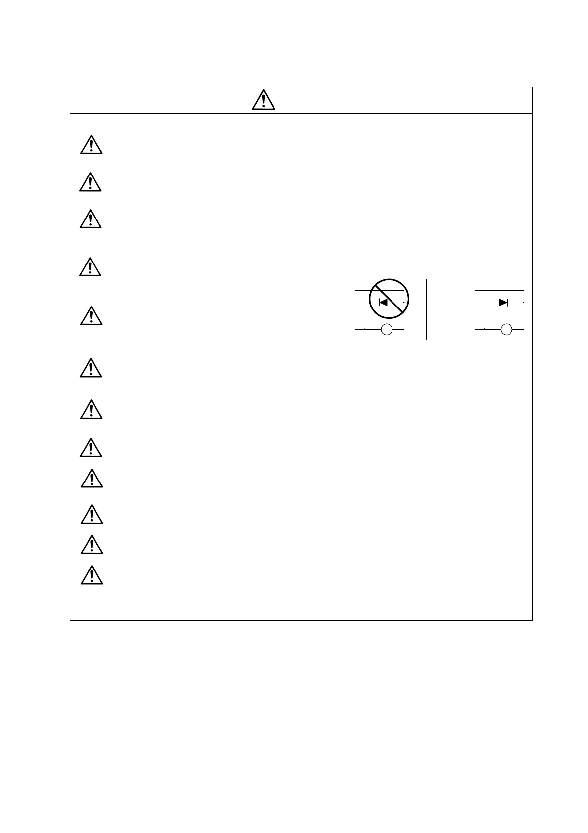
Do not directly connect a commercial
power supply to the servomotor. Failure
to observe this could result in a fault.
Servodrive unit
COM
(24VDC)
Servodrive unit
COM
(24VDC)
When using an inductive load such as a
relay, always connect a diode as a
noise measure parallel to the load.
Controloutput
signal
RA
Control output
signal
When using a capacitance load such as a lamp, always connect a protective resistor a s a
noise measure serial to the load.
Do not reverse the direction of a diode which connect to a DC relay for the control output
signals to suppress a surge. Connecting it backwards could cause the drive unit to
malfunction so that signals are not output, and emergency stop and other safety circuits are
inoperable.
Do not connect/disconnect the cables connected between the units while the power is ON.
Securely tighten the cable connector fixing screw or fixing mechanism. An insecure fixing
could cause the cable to fall off while the power is ON.
When using a shielded cable instructed in the connection manual, always ground the cable
with a cable clamp, etc.
Always separate the signals wires from the drive wire and power lin e.
Use wires and cables that have a wire diameter, heat resistance and flexibility that conforms
to the system.
RA
vi
Page 11
(3) Trial operation and adjustment
Check and adjust each program and parameter before starting operation. Failure to do so
could lead to unforeseen operation of the machine.
Do not make remarkable adjustments and changes as the operatio n could become unstable.
(4) Usage methods
Install an external emergency stop circuit so that the operation can be stopped and power
shut off immediately.
Turn the power OFF immediately if smoke, abnormal noise or odors are generated from the
servo drive unit or servomotor.
Unqualified persons must not disassemble or repair the unit.
Never make modifications.
Reduce magnetic damage by installing a noise filter. The electronic devices used near the
servo drive unit could be affected by magnetic noise.
Use the servo drive unit, servomotor and regenerative resistor with the designa ted
combination. Failure to do so could lead to fires or trouble.
The brake (magnetic brake) assembled into the servomotor are for holding, and must not be
used for normal braking.
There may be cases when holding is not possible due to the magnetic brake's life or the
machine construction (when ball screw and servomotor are coupled via a timing belt, etc.).
Install a stop device to ensure safety on the machine side.
After changing the programs/parameters or after maintenance and inspectio n, always test the
operation before starting actual operation.
Do not enter the movable range of the machine during automatic operation. Never place body
parts near or touch the spindle during rotation.
Follow the power supply specification conditions given in the separate specifications manual
for the power (input voltage, input frequency, tolerable sudden power failure time, etc.).
Set all bits to "0" if they are indicated as not used or empty in the explanation on the bits.
Do not use the dynamic brakes except during the emergency stop. Continuous use of the
dynamic brakes could result in brake damage.
If a breaker is shared by several power supply units, the breaker may not activate when a
short-circuit fault occurs in a small capacity unit. This is dangerous, so never share the
breakers.
CAUTION
vii
Page 12
(5) Troubleshooting
If a hazardous situation is predicted during power failure or product trouble, use a servomotor
with magnetic brakes or install an external brake mechanism.
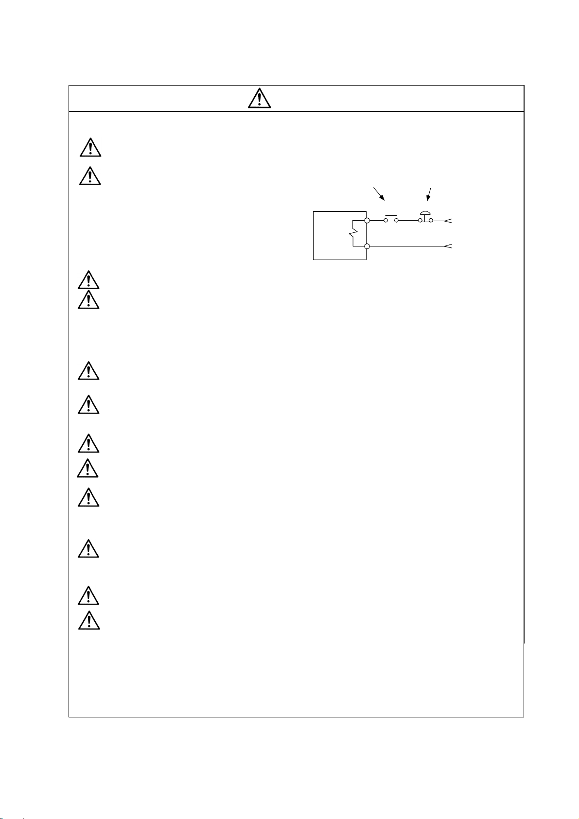
Use a double circuit configuration
that allows the operation circuit for
the magnetic brakes to be operated
even by the external emergency
stop signal.
CAUTION
Shut off with the servomotor
brake control output.
Servomotor
Magnetic
brake
Shut off with NC brake
control PLC output.
MBR
EMG
24VDC
Always turn the input power OFF when an alarm occurs.
Never go near the machine after restoring the power after a power failure, as the machine
could start suddenly. (Design the machine so that personal safety can be ensured even if the
machine starts suddenly.)
(6) Maintenance, inspection and part replacement
Always carry out maintenance and inspection after backing up the servo drive unit's programs
or parameters.
The capacity of the electrolytic capacitor will drop over time. To prevent secondary disasters
due to failures, replacing this part every five years when used under a normal environment is
recommended. Contact the Service Center or Service Station for replacement.
Do not perform a megger test (insulation resistance measurement) during inspections.
If the battery low warning is issued, save the machining programs, tool data and parameters
with an input/output unit, and then replace the battery.
Do not short circuit, charge, overheat, incinerate or disassemble the battery.
(7) Disposal
Dispose of this unit as general industrial waste. Note that MDS Series unit with a heat
dissipating fin protruding from the back of the unit contains substitute Freon. Do not dispose
of this type of unit as general industrial waste. Always return to the Service Center or Service
Station.
Do not disassemble the servo drive unit or servomotor parts.
Dispose of the battery according to local laws.
(8) General precautions
The drawings given in this Specifications and Maintenance Instruction Manual show the covers and
safety partitions, etc., removed to provide a clearer explanation. Always return the covers or partitions
to their respective places before starting operation, and always follow the instructions given in this
manual.
viii
Page 13

CONTENTS
1. Introduction
1-1 Spindle drive system configuration...................................................................................................1-2
1-1-1 System configuration .................................................................................................................1-2
1-1-2 Unit outline type.........................................................................................................................1-3
1-2 Explanation of type...........................................................................................................................1-4
1-2-1 Spindle motor type.....................................................................................................................1-4
1-2-2 Spindle drive unit type ...............................................................................................................1-5
1-2-3 Power supply unit type............................................................................................................... 1-6
1-2-4 AC reactor type..........................................................................................................................1-7
2. Specifications
2-1 Spindle motor....................................................................................................................................2-2
2-1-1 Specifications.............................................................................................................................2-2
2-1-2 Output characteristics ................................................................................................................2-7
2-2 Drive unit......................................................................................................................................... 2-12
2-2-1 Installation environment conditions..........................................................................................2-12
2-2-2 Spindle drive unit ..................................................................................................................... 2-12
2-2-3 Power supply unit.....................................................................................................................2-17
2-2-4 AC reactor................................................................................................................................2-18
2-2-5 D/A output specifications for spindle drive unit........................................................................2-19
2-2-6 Explanation of each part.......................................................................................................... 2-20
2-3 Restrictions and precautions .......................................................................................................... 2-22
2-3-1 Layout of unit ........................................................................................................................... 2-22
2-3-2 Precautions for installing multiple power supply units ............................................................. 2-23
2-3-3 Precautions when installing multiple spindle drive units to one power supply unit .................2-24
3. Characteristics
3-1 Spindle motor....................................................................................................................................3-2
3-1-1 Environmental conditions........................................................................................................... 3-2
3-1-2 Shaft characteristics...................................................................................................................3-2
3-2 Drive unit characteristics...................................................................................................................3-3
3-2-1 Environmental conditions........................................................................................................... 3-3
3-2-2 Heating value............................................................................................................................. 3-4
4. Dedicated Options
4-1 Orientation option ........................................................................................................
4-1-1 Magnetic sensor.........................................................................................................................4-3
4-1-2 Spindle side detector (OSE-1024-3-15-68, OSE-1024-3-15-68-8)........................................... 4-6
4-2 Cables and connectors.....................................................................................................................4-8
4-2-1 Cable connection diagram......................................................................................................... 4-8
4-2-2 List of cables and connectors ....................................................................................................4-9
5. Peripheral Devices
5-1 Selection of wire ...............................................................................................................................5-2
5-1-1 Example of wires by unit............................................................................................................5-2
5-2 Selection the AC reactor, contactor and no-fuse breaker ................................................................ 5-4
5-2-1 Standard selection.....................................................................................................................5-4
5-2-2 Selection of contactor for changing over spindle motor drive wire............................................ 5-5
5-3 Earth leakage breaker ...................................................................................................................... 5-6
5-4 Branch-circuit protection...................................................................................................................5-7
5-4-1 Circuit protector..........................................................................................................................5-7
5-4-2 Fuse protection..........................................................................................................................5-7
5-5 Noise filter.........................................................................................................................................5-8
5-6 Surge absorber................................................................................................................................. 5-9
5-7 Speedometer and load meter......................................................................................................... 5-10
5-8 Cable for peripheral control ............................................................................................................5-11
5-8-1 Cable for external emergency stop..........................................................................................5-11
.....................4-2
Page 14

Appendix 1. Outline Dimension Drawings
Appendix 1-1 Outline dimension drawings of spindle motor.................................................................A1-2
Appendix 1-1-1 SJ Series..................................................................................................................A1-2
Appendix 1-1-2 SJ-V Series..............................................................................................................A1-5
Appendix 1-1-3 SJ-VS Series .........................................................................................................A1-15
Appendix 1-2 Unit outline dimension drawings...................................................................................A1-17
Appendix 1-2-1 Spindle drive unit...................................................................................................A1-17
Appendix 1-2-2 Power supply unit ..................................................................................................A1-21
Appendix 1-2-3 AC rector................................................................................................................A1-25
Appendix 2. Cable and Connector Specifications
Appendix 2-1 Selection of cable ...........................................................................................................A2-2
Appendix 2-1-1 Cable wire and assembly.........................................................................................A2-2
Appendix 2-2 Cable connection diagram..............................................................................................A2-4
Appendix 2-3 Connector outline dimension drawings ..........................................................................A2-8
Appendix 3. Selection
Appendix 3-1 Selecting the power supply.............................................................................................A3-2
Appendix 3-1-1 Selecting according to the continuous rated capacity.............................................A3-2
Appendix 3-1-2 Selection example ...................................................................................................A3-3
Appendix 4. Explanation of Large Capacity Spindle Unit Specifications
Appendix 4-1 Explanation of large capacity spindle unit specifications ...............................................A4-2
Appendix 4-1-1 Outline......................................................................................................................A4-2
Appendix 4-1-2 List of units...............................................................................................................A4-2
Appendix 4-1-3 Selection of AC reactor (B-AL), contactor and NFB................................................A4-2
Appendix 4-1-4 Outline dimension drawings.....................................................................................A4-3
Appendix 4-1-5 Panel cut dimension drawing...................................................................................A4-8
Appendix 4-1-6 Heating value...........................................................................................................A4-9
Appendix 4-1-7 Selecting the power capacity...................................................................................A4-9
Appendix 4-1-8 Selecting the wire size.............................................................................................A4-9
Appendix 4-1-9 Drive unit connection screw size ...........................................................................A4-10
Appendix 4-1-10 Connecting each unit..........................................................................................
.A4-10
Appendix 4-1-11 Restrictions..........................................................................................................A4-12
Appendix 4-1-12 Parameters ..........................................................................................................A4-14
Appendix 4-1-13 Precautions..........................................................................................................A4-14
Appendix 5. Explanation of Small Capacity Spindle Drive Unit Specifications
Appendix 5-1 Explanation of small capacity spindle drive unit specifications......................................A5-2
Appendix 5-1-1 Outline......................................................................................................................A5-2
Appendix 5-1-2 List of units...............................................................................................................A5-2
Appendix 5-1-3 Outline dimension drawings.....................................................................................A5-2
Appendix 5-1-4 Drive unit specifications list......................................................................................A5-4
Appendix 5-1-5 Heating value...........................................................................................................A5-5
Appendix 5-1-6 Selecting the wire size.............................................................................................A5-5
Appendix 5-1-7 Drive unit connection screw size .............................................................................A5-5
Appendix 5-1-8 Restrictions..............................................................................................................A5-6
Appendix 6. Compliance to EU EC Directives
Appendix 6-1 Compliance to EC Directives..........................................................................................A6-2
Appendix 6-1-1 European EC Directives ..........................................................................................A6-2
Appendix 6-1-2 Cautions for EC Directive compliance.....................................................................A6-2
Page 15

Appendix 7. EMC Installation Guidelines
Appendix 7-1 Introduction.....................................................................................................................A7-2
Appendix 7-2 EMC instructions ............................................................................................................A7-2
Appendix 7-3 EMC measures...............................................................................................................A7-3
Appendix 7-4 Measures for panel structure..........................................................................................A7-3
Appendix 7-4-1 Measures for control panel unit...............................................................................A7-3
Appendix 7-4-2 Measures for door....................................................................................................A7-4
Appendix 7-4-3 Measures for operation board panel........................................................................A7-4
Appendix 7-4-4 Shielding of the power supply input section............................................................A7-4
Appendix 7-5 Measures for various cables...........................................................................................A7-5
Appendix 7-5-1 Measures for wiring in panel....................................................................................A7-5
Appendix 7-5-2 Measures for shield treatment.................................................................................A7-5
Appendix 7-5-3 Servomotor power cable..........................................................................................A7-6
Appendix 7-5-4 Servomotor feedback cable.....................................................................................A7-6
Appendix 7-5-5 Spindle motor power cable......................................................................................A7-7
Appendix 7-5-6 Spindle motor feedback cable.................................................................................A7-7
Appendix 7-6 EMC countermeasure parts............................................................................................A7-8
Appendix 7-6-1 Shield clamp fitting...................................................................................................A7-8
Appendix 7-6-2 Ferrite core ..............................................................................................................A7-9
Appendix 7-6-3 Power line filter......................................................................................................A7-10
Appendix 7-6-4 Surge protector......................................................................................................A7-15
Appendix 8. Instruction Manual for Compliance with UL/c-UL Standard
Appendix 8 Instruction Manual for Compliance with UL/c-UL Standard...............................................A8-2
Appendix 9. Compliance with China Compulsory Product Certification (CCC Certification) System
Appendix 9-1 Outline of China Compulsory Product Certification System...........................................A9-2
Appendix 9-2 First Catalogue of Products subject to Compulsory Product Certification .....................A9-2
Appendix 9-3 Precautions for Shipping Products.................................................................................A9-3
Appendix 9-4 Application for Exemption...............................................................................................A9-4
Appendix 9-5 Mitsubishi NC Product Subject to/Not Subject to CCC Certification..............................A9-5
Page 16

1. Introduction
1-1 Spindle drive system configuration .................................................................................................... 1-2
1-1-1 System configuration...................................................................................................................1-2
1-1-2 Unit outline type........................................................................................................................... 1-3
1-2 Explanation of type............................................................................................................................. 1-4
1-2-1 Spindle motor type ...................................................................................................... ................1-4
1-2-2 Spindle drive unit type................................................................................................................. 1-5
1-2-3 Power supply unit type................................................................................................................1-6
1-2-4 AC reactor type ...........................................................................................................................1-7
1 - 1
Page 17
A
1. Introduction
1-1 Spindle drive system configuration
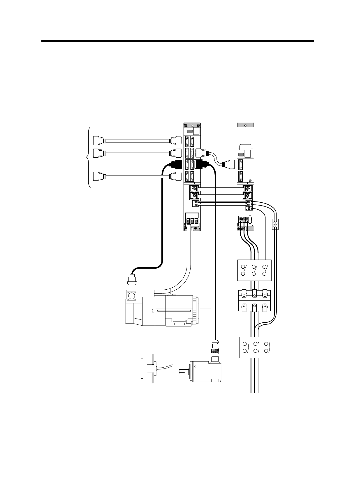
1-1-1 System configuration
NC
•
Sequencer
•
DIO device
•
Meter
•
Spindle drive unit
(MDS-C1-SPA)
Terminator
Power supply unit
(MDS-C1-CV)
Breaker
or
fuse
(Note)
Prepared by
user
Contactor
(Note)
Prepared by
user
C reactor
(B-AL)
Spindle motor
NFB
(Note)
Prepared by
user
spindle side detector (1024p/rev encoder)
Magnesensor or
3-phase 200VAC power supply
1 - 2
Page 18
/
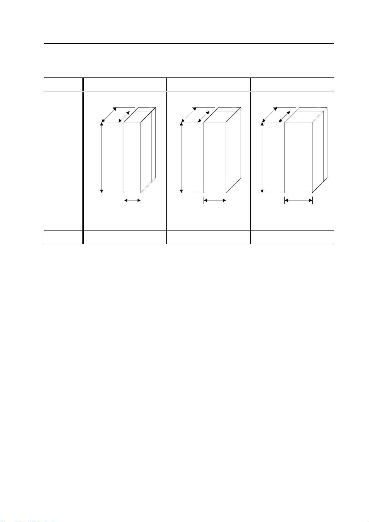
1-1-2 Unit outline type
Unit outline
type
D:260
1. Introduction
B1 C1 D1/D2
200
200
Fin
D:260
263
Fin
D:260
Fin
200
Outline
dimensions
[mm]
Heat dissipa-
tion method
H:380
W:90
Wiring allowance at front: 50mm
Required ventilation space at back:
15mm
Heat radiated outside panel
(forced wind cooling)
H:380
W:120
Wiring allowance at front: 50mm
Required ventilation space at back:
15mm
Heat radiated outside panel
(forced wind cooling)
H:380
W:150
Wiring allowance at front: 50mm
Required ventilation space at back:
15mm (D2: 12mm)
Heat radiated outside panel
(forced wind cooling)
(Note) Refer to "Appendix 1 Outline dimension drawings" for detailed outline drawings.
For customers switching from MDS-A/B Series
The MDS-C1-SPA Series incorporates a highly efficient heat dissipating structure, so the depth of the fin
section is smaller than the MDS-A/B Series. Units with an "S" at the end of the type have a smaller unit
width than the MDS-A/B Series.
When designing the control panel with these unit outline dimensions, it may not be possible to mount the
conventional drive unit.
1 - 3
Page 19
1-2 Explanation of type
1-2-1 Spindle motor type
(1) Standard spindle motor series
1. Introduction
MITSUBISHI AC SPINDLE MOTOR
SJ-V5. 5-01
TYPE
SI CONT 4 POLE
kW r/min
3.7 1500-6000 25 PO WER FAC TOR 82 %
2.8 8000 17
S2 30 min S3 50 %
kW r/min
5.5 1500-6000 33
4.1 8000 23 INSULATION CLASS F
AMB TEMP. 0-40ºC
SERIAL
DATE
FRAME D90F WEIGHT 49 kg IP 44
IEC 34-1 1994 SPEC No.RSV00023*
MITSUBISHI ELECTRIC CORPORATION
Rating nameplate
A(~)
WIND CONNECT
max
MOTOR INPUT(
137 - 162 V
A(~)
AMP INPUT(
max
200-230V 50/60Hz
MADE IN JAPAN
A19103-01
3 PHASES
)
~
)
~
995291-01
U
SJ-
(1) (2) (3) (4) (5)
(5) Z-phase detection
Sym-
bol
Z-phase
presences
(Note) Presence of the Z-phase applies only to the SJ
and SJ-V Series.
None No Z-phase
M Z-phase present
(4) Special specifications
None None
Sym-
bol
Special
specifications
(Note) A number indicating the constant output range is
indicated after the symbol for the wide range
output.
Z High-speed
W
Wide-range
constant output
(3) Base speed
Sym-
bol
Base speed
(Note) The SJ-V Series is indicated with a specification
code (–01 to –99).
A 1500r/min
B 1150r/min
L 5000r/min
X Special
(2) Short time rated output
2.2 2.2kW 22 22kW
3.7 3.7kW 26 26kW
5.5 5.5kW 30 30kW
7.5 7.5kW 37 37kW
11 11kW 45 45kW
Sym-
bol
Short time
rated output
Sym-
bol
Short time
rated output
(Note) The 3.7kW and
smaller or the 37kW
and larger capacities
are available with the
MDS-B-SP Series.
Refer to Appendix 4
and Appendix 5 for
details.
15 15kW 55 55kW
18.5 18.5kW
(1) Motor series
Sym-
bol
Motor series
None Large capacity
V
VS Hollow shaft
Compact medium to large capacity
(Note) Refer to the "MELDAS AC Spindle Built-in Series Standard Specifications" (BFN-14118-04) for
details on the built-in spindle motor.
1 - 4
Page 20
1. Introduction
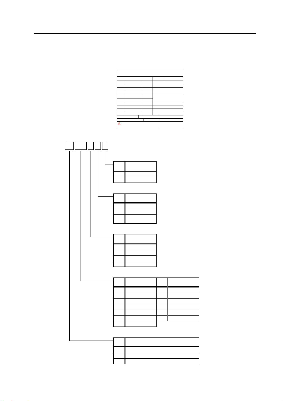
1-2-2 Spindle drive unit type
MITSUBISHI
Motor type
Rated input
Rated output
Current state
Serial No.
TYPE
POWER 5.5kW
INPUT 20A DC270-311V
0.2A 1PH 200/2 00-230V 50/60H z
OUTPUT 18A 3PH 155V 0-240Hz
S/W BNDXXXXXXXXX H/W VER. *
SERIAL# XXXXXXXXXXX DATE 00/01
MITSUBISHI ELECTRIC CORPORATION JAPAN
* XXXXXXXXXXX *
MANUAL# IB-1500148
Rating nameplate
MDS-C1-
(1) -(2)
-
(3)
(3) Option
Symbol
None None
R Orientation function
D Digital speed command input function
T S-analog synchronous tapping function
RD Orientation function and digital speed command input function
RT Orientation function and S-analog synchronous tapping function
(2) Capacity
Symbol
Capa-
city
(kW)
55 5.5
75 7.5
110 11
150 15
185 18.5
220 22
260 26
300 30
(1) Spindle drive unit series
Symbol
Compatible motor rotation
SPA Less than 10,000r/min
SPAH 10,000r/min or more
(Note 1) The 3.7kW and smaller or the 37kW and larger capacities are available with the MDS-B-SP
Series. Refer to Appendix 4 and Appendix 5 for details.
(Note 2) The Outline of unit is determined according to symbol in the above table “(2)” and it is not
affected by the above table “(3)”.
SERVO DRI VE UNIT
MDS-C1-SPA-55
Compatible optional function
Outline type
(unit width)
B1
(90mm wide)
C1
(120mm wide)
D1
(150mm wide)
D2
(150mm wide)
speed
(Note) The 3.7kW and smaller or
the 37kW and larger
capacities are available
with the MDS-B-SP
Series.
Refer to Appendix 4 and
Appendix 5 for details.
Details
Standard specifications
1 - 5
Page 21

1. Introduction
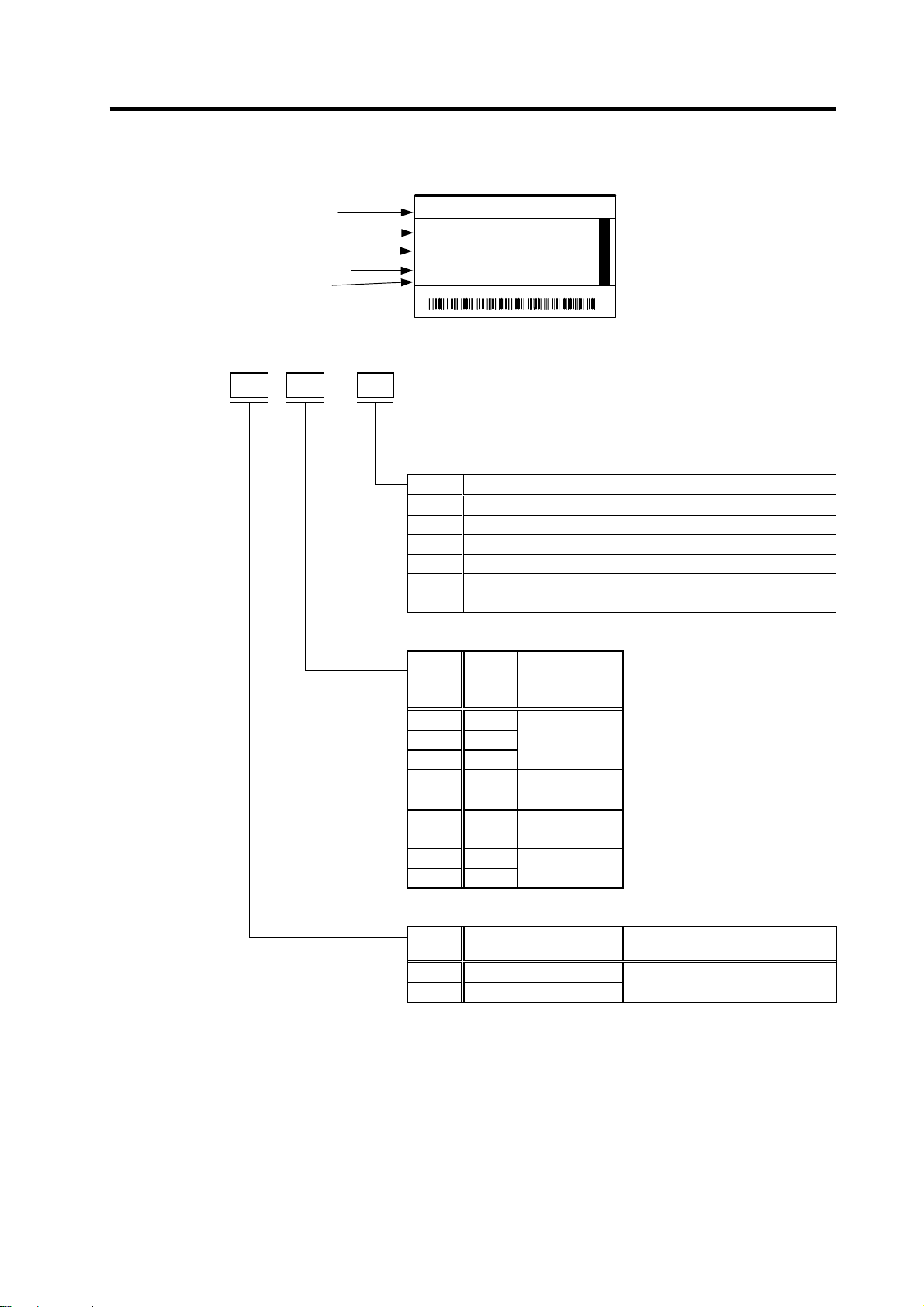
1-2-3 Power supply unit type
MITSUBISHI
Motor type
Rated input
Rated output
Current state
Serial No.
TYPE
POWER 15kW
INPUT 49A 3PH 200/200-230V 50/60Hz
0.2A 1PH 200/200-230V 50/60Hz
OUTPUT 58A DC270-311V
DIN VDE0160 MANUAL# BNP-C3000
S/W BND538W000A1 H/W VER. D
SERIAL # XXXXXXXXXXX
MITSUBISHI ELECTRIC CO RPO RAT I ON JAPAN
* X X X X X X X X X X X *
Rating nameplate
MDS-C1-
CV-150 15
CV-185 18.5
CV-220 22
CV-260 26
CV-300 30
CV-370 37
(1)
(1) Motor
type
MDS-C1CV-37 3.7
CV-55 5.5
CV-75 7.5
CV-110 11
Power supply unit
Capa-
Outline type
city
(unit width)
(kW)
(60mm wide)
(90mm wide)
(120mm wide)
(150mm wide)
A2
B1
C1
D1
(Note 1) This is an optional part, and must be prepared by the user.
(Note 2) The 45kW and larger capacities are available with the MDS-B-CVE Series.
Refer to Appendix 4 for details.
POWER SUPPLY UNIT
MDS-C1-CV-150
3040
DATE 02/09
Compatible AC
reactor
B-AL-7.5K S-N25 200VAC NF50CS3P-40A05
B-AL-11K S-N35 200VAC NF50CS3P-50A05
B-AL-18.5K S-N50 200VAC NF100CS3P-100A05
B-AL-30K S-N80 200VAC NF225CS3P-150A05
B-AL-37K S-N150 200VAC NF225CS3P-175A05
Compatible
contactor
(Mitsubishi)
(Note 1)
Compatible NFB
(Mitsubishi)
(Note 1)
1 - 6
Page 22
1-2-4 AC reactor type
Type
B-AL-7.5K
Nameplate
1. Introduction
Top surf ace of A C react or
B-AL-
(1)
11K 11 MDS-C1-CV-110
MDS-C1-CV-150
MDS-C1-CV-220
MDS-C1-CV-260
37K 37 MDS-C1-CV-370
AC reactor
Motor
type
B-AL-
7.5K 7.5
18.5K 18.5
30K 30
Capa-
city
(kW)
Compatible
power supply unit
MDS-C1-CV-37
MDS-C1-CV-55
MDS-C1-CV-75
MDS-C1-CV-185
MDS-C1-CV-300
1 - 7
Page 23

2. Specifications
2-1 Spindle motor.....................................................................................................................................2-2
2-1-1 Specifications .............................................................................................................................. 2-2
2-1-2 Output characteristics.................................................................................................................. 2-7
2-2 Drive unit..........................................................................................................................................2-12
2-2-1 Installation environment conditions........................................................................................... 2-12
2-2-2 Spindle drive unit.......................................................................................................................2-12
2-2-3 Power supply unit...................................................................................................................... 2-17
2-2-4 AC reactor ................................................................................................................................. 2-18
2-2-5 D/A output specifications for spindle drive unit .........................................................................2-19
2-2-6 Explanation of each part............................................................................................................2-20
2-3 Restrictions and precautions............................................................................................................ 2-22
2-3-1 Layout of unit.............................................................................................................................2-22
2-3-2 Precautions for installing multiple power supply units............................................................... 2-23
2-3-3 Precautions when installing multiple spindle drive units to one power supply unit...................2-24
2 - 1
Page 24
2. Specifications
2-1 Spindle motor
2-1-1 Specifications
Base rotation speed
Spindle motor type
2.2-01 3.7-01 5.5-01 7.5-01 11-01 15-01 18.5-01 22-01 26-01
Compatible spindle drive unit type
MDS-B/C1-
Continuous rating
Output
capacity
Base speed [r/min] 1500
Maximum speed [r/min] 10000 8000 6000
Frame No. A90 B90 D90 A112 B112 A160 B160 C160
Continuous rated torque [N·m] 9.5 14.0 23.5 35.0 47.7 70.0 95.5 118 140
GD2 [kg·m2] 0.027 0.035 0.059 0.098 0.12 0.23 0.23 0.32 0.38
Inertia [kg·m2] 0.007 0.009 0.015 0.025 0.03 0.06 0.06 0.08 0.10
Tolerable radial load [N] 980 1470 1960 2940
Cooling
fan
Environment
Weight [kg] 25 30 49 60 70 110 135 155
Insulation Class F
(Note 1) The rated output is guaranteed at the rated input voltage (200/220/230VAC) to the power supply unit.
If the input voltage fluctuates and drops below 200VAC, the rated output may not be attained.
(Note 2) The 50%ED rating applies for a 10-minute cycle time consisting of ON for five minutes and OFF for five minutes.
(Note 3) The 3.7kW and smaller capacities are available with the MDS-B-SPA Series. Refer to Appendix 5 for details.
[kW]
30-minute rating
50%ED rating
[kW]
Input voltage Single-phase 200V 3-phase 200V
Maximum power
consumption
Ambient temperature Operation: 0 to 40°C (non freezing), Storage: –20 to 65°C (non freezing)
Ambient humidity
Atmosphere Indoors (no direct sunlight); no corrosive gas, inflammable gas, oil mist, or dust
Altitude
MDS-B-
SPAH-
MDS-B-
SPAH-
22
1.5 2.2 3.7 5.5 7.5 11 15 18.5 22
2.2 3.7 5.5 7.5 11 15 18.5 22 26
42W 40W 63W
SPA-55 SPA-75
37
Operation: 90%RH or less (non condensing),
Storage: 90%RH or less (non condensing)
Operation: 1000 meters or less above sea level,
Storage: 1000 meters or less above sea level
1500r/min Series
SJ-V
SPA-
110
SPA-
150
SPA-
185
SPA-
220
SPA-
300
CAUTION
When replacing the SJ-V series by the conventional SJ series, the shorter L
dimension is applied.
2 - 2
Page 25
2. Specifications
Large capacity series
Spindle motor type
30A 37BP 45BP 55-01
Compatible spindle drive unit type
MDS-B-
Continuous rating
Output
capacity
Base speed [r/min] 1500 1150
Maximum speed [r/min] 4500 3450
Frame No. B160 B180 A200 A225
Continuous rated torque [N·m] 140 249 307 374
GD2 [kg·m2] 0.69 1.36 2.19 3.39
Inertia [kg·m2] 0.17 0.34 0.55 0.85
Tolerable radial load [N] 2940 4900 5880 5880
Cooling
fan
Environment
Weight [kg] 200 300 390 450
Insulation Class F
(Note 1) The rated output is guaranteed at the rated input voltage (200/220/230VAC) to the power supply unit.
If the input voltage fluctuates and drops below 200VAC, the rated output may not be attained.
(Note 2) The 50%ED rating applies for a 10-minute cycle time consisting of ON for five minutes and OFF for five minutes.
(Note 3) The 37kW and larger capacities are available with the MDS-B-SPA Series. Refer to Appendix 4 for details.
[kW]
30-minute rating
50%ED rating
[kW]
Input voltage Single-phase 200V 3-phase 200V
Maximum power
consumption
Ambient temperature Operation: 0 to 40°C (non freezing), Storage: –20 to 65°C (non freezing)
Ambient humidity
Atmosphere Indoors (no direct sunlight); no corrosive gas, inflammable gas, oil mist, or dust
Altitude
SPA-370 SPA-450 SPA-550
22 30 37 45
30 37 45 55
130W 60W 115W
Operation: 90%RH or less (non condensing),
Operation: 1000 meters or less above sea level,
Storage: 1000 meters or less above sea level
SJ- SJ-V
Storage: 90%RH or less (non condensing)
2 - 3
Page 26
2. Specifications
Wide range (1:8) constant output series
Spindle motor type
11-01 11-09 15-03 18.5-03 22-05 22XW5 22XW8
Compatible spindle drive unit type
MDS-C1-
Continuous rating
Output
capacity
Base speed [r/min] 750
Maximum speed [r/min] 6000 5000 4000
Frame No. B112 A160 B160 B180 A200
Continuous rated torque [N·m] 47.1 70.0 95.5 115 140 239 294
GD2 [kg·m2] 0.12 0.23 0.23 0.32 0.32 1.36 2.19
Inertia [kg·m2] 0.03 0.06 0.06 0.08 0.08 0.34 0.55
Tolerable radial load [N] 1960 2940 3920 5880
Cooling
fan
Environment
Weight [kg] 70 110 135 300 390
Insulation Class F
(Note 1) The rated output is guaranteed at the rated input voltage (200/220/230VAC) to the power supply unit.
If the input voltage fluctuates and drops below 200VAC, the rated output may not be attained.
(Note 2) The 50%ED rating applies for a 10-minute cycle time consisting of ON for five minutes and OFF for five minutes.
[kW]
30-minute rating
50%ED rating [kW]
Input voltage 3-phase 200V
Maximum power
consumption
Ambient temperature Operation: 0 to 40°C (non freezing), Storage: –20 to 65°C (non freezing)
Ambient humidity
Atmosphere Indoors (no direct sunlight); no corrosive gas, inflammable gas, oil mist, or dust
Altitude
SPA-110 SPA-185 SPA-220 SPA-260 SPA-300 SPA-300
3.7 5.5 7.5 9 11 19.5 18.5
5.5 7.5 9 11 15 22 22
40W 63W 180W 60W
Operation: 1000 meters or less above sea level,
SJ-V SJ-
Operation: 90%RH or less (non condensing),
Storage: 90%RH or less (non condensing)
Storage: 1000 meters or less above sea level
Wide range constant
output series
600
(800)
Single-
phase
200V
550
(600)
3-phase
200V
2 - 4
Page 27
2. Specifications
High-speed series
Spindle motor type
3.7-02ZM 7.5-03ZM 11-06ZM 11-08ZM 22-06ZM 30-02ZM
Compatible spindle drive unit type
MDS-B/C1-
Continuous rating
Output
capacity
Base speed [r/min]
Maximum speed [r/min]
Frame No.
Continuous rated torque [N·m]
GD2 [kg·m2]
Inertia [kg·m2]
Tolerable radial load [N]
Cooling
fan
Environment
Weight [kg]
Insulation
(Note 1) The rated output is guaranteed at the rated input voltage (200/220/230VAC) to the power supply unit.
If the input voltage fluctuates and drops below 200VAC, the rated output may not be attained.
(Note 2) The 50%ED rating applies for a 10-minute cycle time consisting of ON for five minutes and OFF for five minutes.
(Note 3) The 3.7kW and smaller capacities are available with the MDS-B-SPA Series. Refer to Appendix 5 for details.
[kW]
30-minute rating
50%ED rating
[kW]
Input voltage
Maximum power
consumption
Ambient temperature
Ambient humidity
Atmosphere
Altitude
MDS-B-
SPAH-37
2.2 5.5 5.5 7.5
3.7
(15min. rating)
3000 1500
15000 12000 8000
A90
7.0 35.0 35.0 47.7 70.0 118
0.027 0.098 0.098 0.12 0.23 0.32
0.007 0.025 0.025 0.03 0.06 0.08
490 980 1470 1960
Single-phase
200V
42W 40W 63W
Indoors (no direct sunlight); no corrosive gas, inflammable gas, oil mist, or dust
25 60 70 125 155
SPAH-110 SPAH-150 SPA-185
7.5 7.5 11 15 22
A112
Operation: 0 to 40°C (non freezing), Storage: –20 to 65°C (non freezing)
Operation: 90%RH or less (non condensing),
Storage: 90%RH or less (non condensing)
Operation: 1000 meters or less above sea level,
Storage: 1000 meters or less above sea level
SJ-V
3-phase 200V
Class F
B112
SPA-220
11
A160
SPA-300
18.5
B160
2 - 5
Page 28
2. Specifications
Hollow shaft series
Spindle motor type
7.5-03ZM 22-06ZM 30-02ZM
Compatible spindle drive unit type
MDS-C1-
Continuous rating
Output
capacity
Base speed [r/min] 1500 1500
Maximum speed [r/min] 12000 8000
Frame No. A112 A160 B160
Continuous rated torque [N·m] 35.0 70.0 118
GD2 [kg·m2] 0.099 0.23 0.32
Inertia [kg·m2] 0.025 0.058 0.08
Tolerable radial load [N] 0 (Note 3) 0 (Note 3) 0 (Note 3)
Cooling
fan
Environment
Weight [kg] 65 115 140
Insulation Class F
(Note 1) The rated output is guaranteed at the rated input voltage (200 to 230VAC) to the power supply unit.
(Note 2) The 50%ED rating applies for a 10-minute cycle time consisting of ON for five minutes and OFF for five minutes.
(Note 3) Do not apply a radial load.
[kW]
30-minute rating
50%ED rating
[kW]
Input voltage Single-phase 200V 3-phase 200V
Maximum power
consumption
Ambient temperature
Ambient humidity
Atmosphere
Altitude
SPAH-110 SPA-220 SPA-300
5.5 11 18.5
7.5 15 22
40W 40W
Operation: 0 to 40°C (non freezing),
Storage: –20 to 65°C (non freezing)
Operation: 90%RH or less (non condensing),
Storage: 90%RH or less (non condensing)
Indoors (no direct sunlight); no corrosive
gas, inflammable gas, oil mist, or dust
Operation: 1000 meters or less above sea level,
Storage: 1000 meters or less above sea level
SJ-VS
2 - 6
Page 29
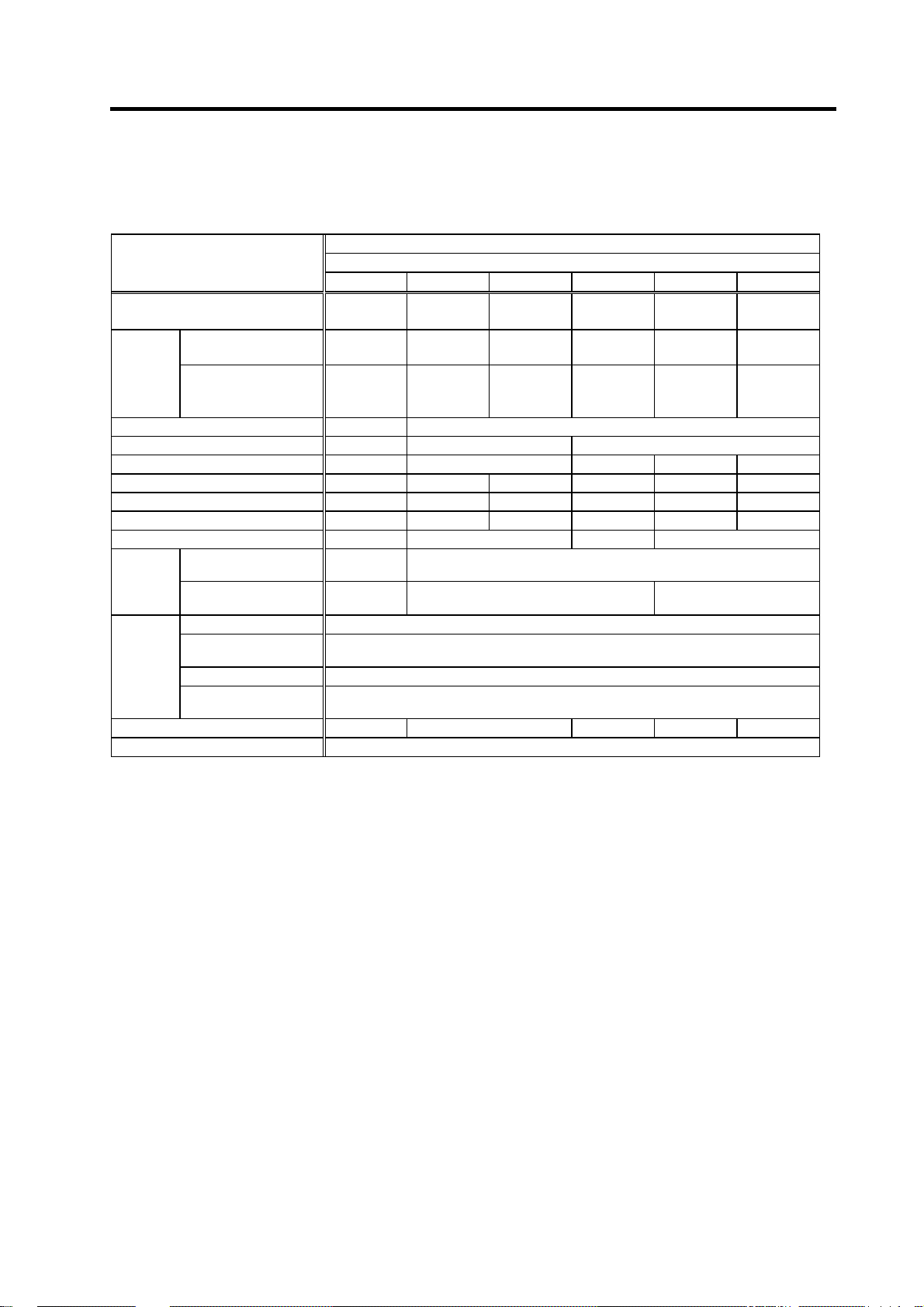
2-1-2 Output characteristics
[Base rotation speed 1500r/min series SJ-V2.2-01]
2. Specifications
[Base rotation speed 1500r/min series SJ-V3.7-01]
2.2
15-minute rating
1.5
1.3
0.9
Output [kW]
0
0 1500 6000
Continuous rating
Rotation speed [r/min]
[Base rotation speed 1500r/min series SJ-V5.5-01]
5.5
]
4.1
3.7
2.8
15-minute rating
Continuous rating
Output [kW]
0
0 1500 6000
Rotation speed [r/min]
3.7
15-minute rating
2.2
Output [kW]
1.3
10000 0 1500 6000
0
Continuous rating
10000
Rotation speed [r/min]
[Base rotation speed 1500r/min series SJ-V7.5-01]
7.5
5.5
4.1
15-minute rating
Continuous rating
Output [kW]
8000
0
0 1500 6000
Rotation speed [r/min]
8000
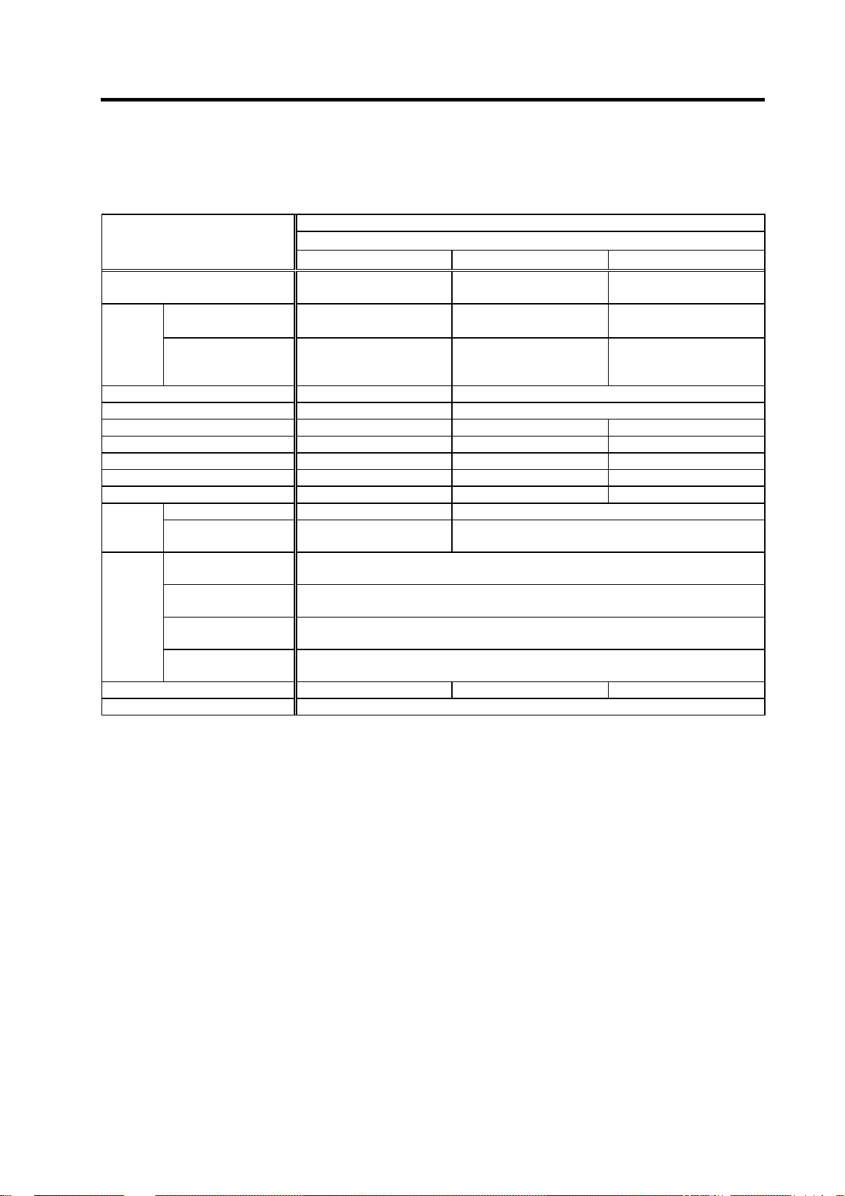
[Base rotation speed 1500r/min series SJ-V11-01] [Base rotation speed 150 0 r/min series SJ-V15-01]
11
8.3
7.5
5.6
15-minute rating
Continuous rating
Output [kW]
0
0 1500 4500
Rotation speed [r/min]
[Base rotation speed 1500r/min series SJ-V18.5-01]
18.5
13.9
11.3
15
15-minute rating
Continuous
Output [kW]
6000
15
8.3
15-minute rating
11
Continuous rating
Output [kW]
0
0 1500 4500
Rotation speed [r/min]
[Base rotation speed 150 0 r/min series SJ-V22-01]
22
18.5
16.5
13.9
15-minute rating
Continuous rating
Output [kW]
6000
0
0 1500 4500
Rotation speed [r/min]
6000
2 - 7
0
0 1500 4500
Rotation speed [r/min]
6000
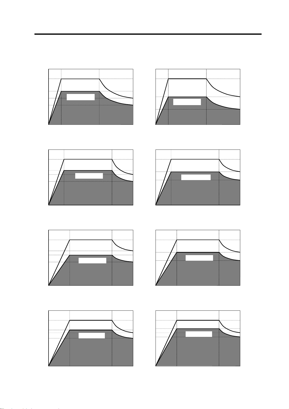
Page 30
2. Specifications
[Base rotation speed 1500r/min series SJ-V26-01]
26
22
30-minute rating
Continuous rating
Output [kW]
0
0 1500
Rotation speed [r/min]
[Large capacity series SJ-30A]
30
30-minute rating
22
Continuous rating
Output [kW]
0
0 1500
Rotation speed [r/min]
6000
4500
37
30
Output [kW]
0
0 1150
[Large capacity series SJ-37BP]
30-minute rating
Continuous rating
3450
Rotation speed [r/min]
[Large capacity series SJ-45BP]
45
37
30-minute rating
Continuous rating
Output [kW]
0
0 1150
Rotation speed [r/min]
3450
55
45
Output [kW]
0
0 1150
[Large capacity series SJ-V55-01]
30-minute rating
Continuous
3450
Rotation speed [r/min]
2 - 8
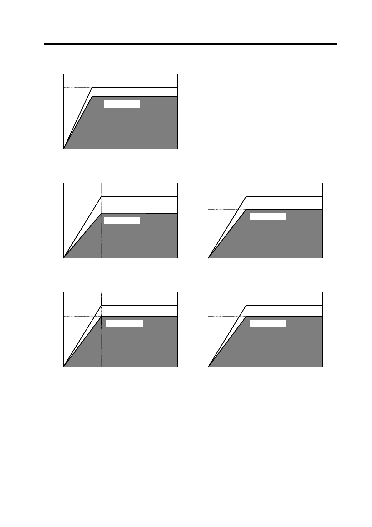
Page 31

2. Specifications
[Wide range (1:8) constant output series SJ-V11-01]
[Wide range (1:8) constant output seri e s SJ-V11-09]
5.5
3.7
30-minute rating
Continuous rating
Output [kW]
0
0 750
Rotation speed [r/min]
[Wide range (1:8) constant output series SJ-V15-03]
9
7.5
30-minute rating
Continuous rating
Output [kW]
0
0 750
Rotation speed [r/min]
6000
6000
7.5
5.5
30-minute rating
Continuous rating
Output [kW]
0
0750
Rotation speed [r/min]
[Wide range (1:8) constant output seri e s SJ-V18.5-03]
11
9
30-minute rating
Continuous rating
Output [kW]
0
0750
Rotation speed [r/min]
6000
6000
[Wide range (1:8) constant output series SJ-V22-05]
15
11
30-minute rating
Continuous rating
Output [kW]
0
0 750
Rotation speed [r/min]
[Wide range constant output series SJ-22XW5]
22
19.5
13
11.5
30-minute rating
Continuous rating
Output [kW]
6000
[Wide range constant output series SJ-22XW8]
22
18.5
30-minute rating
Continuous rating
0
600
5000
Rotation speed [r/min]
2 - 9
0
0 500
6000 800 3000
Rotation speed [r/min]
4000
Page 32

2. Specifications
[High speed series SJ-V3.7-02ZM
]
[High speed series SJ-V7.5-03ZM
]
3.7
3
2.2
1.8
Output [kW]
0
0 3000 12000
15-minute rating
Continuous rating
Rotation speed [r/min]
[High speed series SJ-V11-06ZM
7.5
5.5
30-minute rating
Continuous rating
Output [kW]
0
0 1500
Rotation speed [r/min]
7.5
15000
6.3
5.5
4.6
Output [kW]
0
0 1500 10000
]
11
7.5
[High speed series SJ-V11-08ZM
15-minute rating
Continuous rating
Rotation speed [r/min]
30-minute rating
Continuous rating
12000
]
Output [kW]
12000
0
0 1500
Rotation speed [r/min]
8000
15
11
Output [kW]
0
0 1500
[High speed series SJ-V22-06ZM
30-minute rating
Continuous rating
Rotation speed [r/min]
]
8000
22
18.5
Output [kW]
0
0 1500
[High speed series SJ-V30-02ZM
30-minute rating
Continuous rating
Rotation speed [r/min]
]
8000
2 - 10
Page 33

2. Specifications
[Hollow shaft series SJ-V7.5-03ZM
]
[Hollow shaft series SJ-V22-06ZM
]
7.5
5.5
Output [kW]
0
0 1500
22
18.5
Output [kW]
0
0 1500
30-minute rating
Continuous rating
Rotation speed [r/min]
[Hollow shaft series SJ-V30-02ZM
30-minute rating
Continuous rating
Rotation speed [r/min]
15
11
30-minute rating
Continuous rating
Output [kW]
12000
0
0 1500
Rotation speed [r/min]
8000
]
8000
2 - 11
Page 34

2. Specifications
2-2 Drive unit
2-2-1 Installation environment conditions
Common installation environment conditions for servo, spindle and power supply unit are shown below.
Ambient
temperature
Environment
Ambient humidity
Atmosphere
Altitude
Vibration/impact
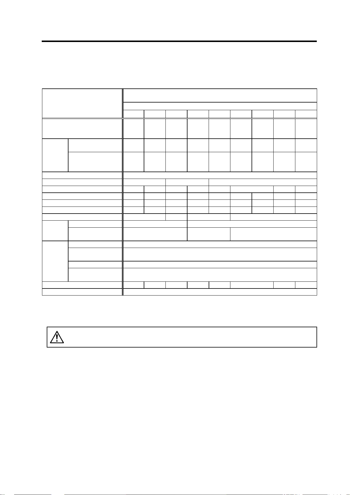
2-2-2 Spindle drive unit
(1) Specifications
Spindle drive
unit type
Rated output [kW] 3.7 5.5 7.5 11 15 18.5 22 26
Output
Input
Control
power
Earth leakage current [mA] 6 (MAX. 15)
Control method Sine wave PWM control method, current control method
Braking Regenerative braking
Speed command input
External analog output 0 to +10V, 2ch (speed meter output, load meter output, data for various adjustments)
Structure Protection type (Protection method: IP20 [over all] / IP00 [Terminal block TE1])
Cooling method Forced wind cooling (fin)
Weight [kg] 4.4 5.7 6.5 6.3
Heat radiated
at rated output
Noise Less than 55dB
Spindle drive unit MDS-C1-SP Series
MDS-C1-SPMDS-C1-SPH-
Rated voltage [V] 155AC
Rated current [A] 18 26 37 49 63 79 97 130
Rated voltage [V] 270 to 311DC
Rated current [A] 20 30 41 58 76 95 115 144
Voltage [V] 200/200 to 230AC
Frequency [Hz] 50/60
Current [A] Max. 0.2
Rush current
Rush
conductivity
time
[A]
[ms]
[W] 108 137 181 235 342 366 483 620
Operation: 0 to 55°C (with no freezing), Storage / Transportation: -15°C to 70°C (with no freezing)
Operation: 90%RH or less (with no dew condensation)
Storage / Transportation: 90%RH or less (with no dew condensation)
With no corrosive gas, inflammable gas, oil mist or dust
Operation/Storage: 1000 meters or less above sea level, Transportation: 10000 meters or less above sea level
55 75 110 150 185 220 260 300
Analog voltage ±10V (or +10V) MAX (input impedance approx.10kΩ),
or digital (option) (12 bit binary, signed binary, BCD code 2 digits, BCD code 3 digits)
Indoors (no direct sunlight)
2
4.9m/s
(0.5G) / 49m/s2 (5.0G)
MAX. 35
MAX. 6
2 - 12
Page 35

2. Specifications
(2) Spindle drive unit function specifications list
Function
S analog command voltage input±10V ○ ○ ○ ○ ○ ○
S analog command voltage input 0 to +10V ○ ○ ○ ○ ○ ○
Machine ready complete input ○ ○ ○ ○ ○ ○
Basic
function
Forward run/reverse run command input ○ ○ ○ ○ ○ ○
Override analog input ○ ○ ○ ○ ○ ○
Torque limit 1 to 3 input ○ ○ ○ ○ ○ ○
Gear selection1, 2 input ○ ○ ○ ○ ○ ○
Alarm reset input ○ ○ ○ ○ ○ ○
Emergency stop input ○ ○ ○ ○ ○ ○
Speed selection 1 to 3 input ○ ○ ○ ○ ○ ○
Override valid/invalid input ○ ○ ○ ○ ○ ○
L coil selection input ○ ○ ○ ○ ○ ○
Index forward run/reverse run input - ○ - - ○ ○
Digital speed command input - - ○ - ○ S-analog high-speed tapping input - - - ○ - ○
Sub-motor selection input ○ ○ ○ ○ ○ ○
Speed meter output ○ ○ ○ ○ ○ ○
Load meter output ○ ○ ○ ○ ○ ○
Controller emergency output signal (contact output) ○ ○ ○ ○ ○ ○
Pulse feedback output signal ○ ○ ○ ○ ○ ○
Zero speed output signal ○ ○ ○ ○ ○ ○
Up-to-speed output signal ○ ○ ○ ○ ○ ○
Speed detection output signal ○ ○ ○ ○ ○ ○
Torque reach output signal ○ ○ ○ ○ ○ ○
Miscellaneous function
In torque limit output signal ○ ○ ○ ○ ○ ○
In motor forward run/reverse run output signal ○ ○ ○ ○ ○ ○
In alarm output signal ○ ○ ○ ○ ○ ○
In emergency stop output signal ○ ○ ○ ○ ○ ○
In ready ON output signal ○ ○ ○ ○ ○ ○
Current detect output signal ○ ○ ○ ○ ○ ○
In coil changeover output signal ○ ○ ○ ○ ○ ○
In L coil selected output signal ○ ○ ○ ○ ○ ○
Alarm code output 1 to 4 signal ○ ○ ○ ○ ○ ○
Orientation complete output signal - ○ - - ○ ○
Positioning complete output signal - ○ - - ○ ○
In 1-drive unit 2-motor changeover output signal ○ ○ ○ ○ ○ ○
In sub-motor selection output signal ○ ○ ○ ○ ○ ○
1-drive unit
2-motor
changeover
Orientation
Digital speed
command
Optional function
S-analog
highspeed
tapping
○: available -: not available
(Note 1)
For input excluding a basic function input, up to 12 points can be selected.
(Note 2)
For output, up to 8 points can be selected for open emitter, and up to 6 points for open collector.
(Note 3)
(Note 4)
(Note 5)
When using the override input terminal in S analog input, and when using the digital speed command, the override function
can not be used.
When the orientation is not applied in the S-analog high-speed tapping specification, Z phase is not output from the pulse
feedback signal. A position loop of spindle must be operated in the NC side.
Spindle motor + spindle motor
(FR-TK unit is required.)
Spindle motor + general-purpose motor
Magnetic sensor orientation (1 point) - ○ - - ○ ○
Encoder orientation (multipoint • index) - ○ - - ○ ○
Motor PLG orientation (multipoint
12 bit binary - - ○ - ○ Signed binary - - ○ - ○ BCD3 digits - - ○ - ○ -
BCD2 digits - 1024p/rev encoder
specification
Motor PLG
specification
Only for encoder orientation - - - - -
1) Motor PLG orientation - - - - - ○
2) Magnetic sensor orientation - - - - - ○
3) Orientation not available - - - ○ - ○
• index ) - ○ - - ○ ○
MDS-C1-SPA(H)-55~300*
*: Option symbol
None R D T RD RT
○ ○ ○ ○ ○ ○
○ ○ ○ ○ ○ ○
○ - ○ -
○
2 - 13
Page 36

2. Specifications
(3) Details on spindle drive unit function specifications
(a) Speed command input
1) Analog speed command input
Input voltage -10 to +10V 0 to +10V
Tolerable maximum input
voltage
Input part connector, pin No.
Resolution
Tolerable maximum input does not guarantee the speed linearity, but specifies the maximum voltage in which
(Note 1)
When using bipolar input When using unipolar input
-15 to +15V -15 to +15V
Between CN8A-No.7 pin (SE1) and
No.8 pin (SE2)
10V/ approx. 1940 divisions
(approx. 5.1mV)
the drive unit will not be damaged.
2) Digital speed command input (option)
Binary
(12bit binary)
Input Contact input Sink • source input available
Tolerable maximum input
voltage
Input part connector CN12
Resolution
Motor maximum
speed/4095
3) Speed selection input
With this function, 8 patterns of speed commands are selected using up to 3 bits in
combination. Speed can be set with a parameter.
Speed selection
Input Contact input Sink and source input available
Tolerable maximum input
voltage
Input part connector Select maximum three of CN10 general-purpose input
Minimum setting unit 1r/min
(b) Override input
This function is valid when the override input contact set with the
turned ON.
When using unipolar input
Input voltage 0 to +10V
Tolerable maximum input
voltage
Input part connector, pin No. Between CN8A-No.17 pin (OR2) and No.18 pin (OR1)
Resolution 10V/ approx. 3570 divisions (approx. 2.8mV)
When using unipolar analog input, digital speed command input and speed selection for the speed command,
(Note 1)
the override function cannot be used.
Between CN8A-No.17 pin (OR2) and
No.18 pin (OR1)
10V/ approx. 3570 divisions
(approx. 2.8mV)
Signed binary BCD code 3digits BCD code 2digits
26.4V
Motor maximum
speed/2048
-15 to +15V
Motor maximum
speed/999
26.4V
Motor maximum
speed/99
general-purpose input is
2 - 14
Page 37

2. Specifications
(c) Orientation function (spindle set position stop function) (option)
1) 1 point orientation
When the orientation signal is input, the spindle is stopped at the set position determined
by an internal parameter.
When using external 1024p/rev
encoder or motor PLG
Available stop position
setting range
Stop position resolution 360°/4096 divisions Approx. 5°/512 divisions
Repeated stop position
accuracy
(Note 1)
(Note 2)
(Note 3)
The repeated stop accuracy or resolution in the above table may not satisfy the accuracy according to
backlash or friction torque, etc of machine.
When using magnetic sensor, the position accuracy or stop position range differs from the above table
according to the installation radius.
Motor PLG orientation is possible only when the spindle and motor are coupled, when they are coupled at 1:1
with gears, or when they are coupled at 1:1 (pulley ratio) with a timing belt.
The Z phase signal must be provided to the motor speed detector.
360°
±
0.1° ±0.1°
When using magnetic sensor
±5°
based on center of magnet and sensor
2) Orientation
The spindle stop position in the orientation command input is changed arbitrarily using
external 12 bits stop position command.
When using external 1024p/rev encoder or motor PLG
Available stop position
setting range
Stop position resolution 360°/4096 divisions
Repeated stop position
accuracy
The repeated stop accuracy or resolution in the above table may not satisfy the accuracy according to
(Note 1)
(Note 2)
backlash or friction torque, etc of machine.
Motor PLG orientation is possible only when the spindle and motor are coupled, when they are coupled at 1:1
with gears, or when they are coupled at 1:1 (pulley ratio) with a timing belt.
The Z phase signal must be provided to the motor speed detector.
360°(arbitrary according to external stop command)
±
0.1°
3) Multi-point indexing orientation
By setting the orient command and indexing forward run/reverse run to the
general-purpose input, the stop position is changed arbitrarily without one rotation of the
spindle.
When using external 1024p/rev encoder or motor PLG
Available stop position
setting range
Stop position resolution 360°/4096 divisions
Repeated stop position
accuracy
The repeated stop accuracy or resolution in the above table may not satisfy the accuracy according to
(Note 1)
(Note 2)
backlash or friction torque, etc of machine.
Motor PLG orientation is possible only when the spindle and motor are coupled, when they are coupled at 1:1
with gears, or when they are coupled at 1:1 (pulley ratio) with a timing belt.
The Z phase signal must be provided to the motor speed detector.
360°(arbitrary according to external stop command)
±
0.1°
2 - 15
Page 38

2. Specifications
(d) S-analog high-speed tapping function (option)
By structuring the position loop in the NC side and synchronizing with the servo axis, tap
cutting is carried out without using floating tap chuck. Setting the S-analog high-speed tapping
input to the general-purpose input and adding the speed command voltage to the S-analog
input section realize this function.
(e) 1-drive unit 2-motor changeover function
One spindle drive unit rotates two motors that are not used simultaneously. The motor drive
wire is changed over with contactor, and signal wire with FR-TK to select which one to use.
When two motors must be rotated simultaneously, this function cannot be used.
(f) Coil changeover function
This function is used when using the coil changeover motor to gain an extensive constant
output range without a gear. The coil selection signal is set to the general-purpose input, and a
contactor for coil changeover, which is connected with the motor drive wire, is changed over
through a compact relay by turning ON/OFF this signal.
For details on each specification above, refer to MDS-C1-SPA Instruction Manual.
2 - 16
Page 39

2. Specifications
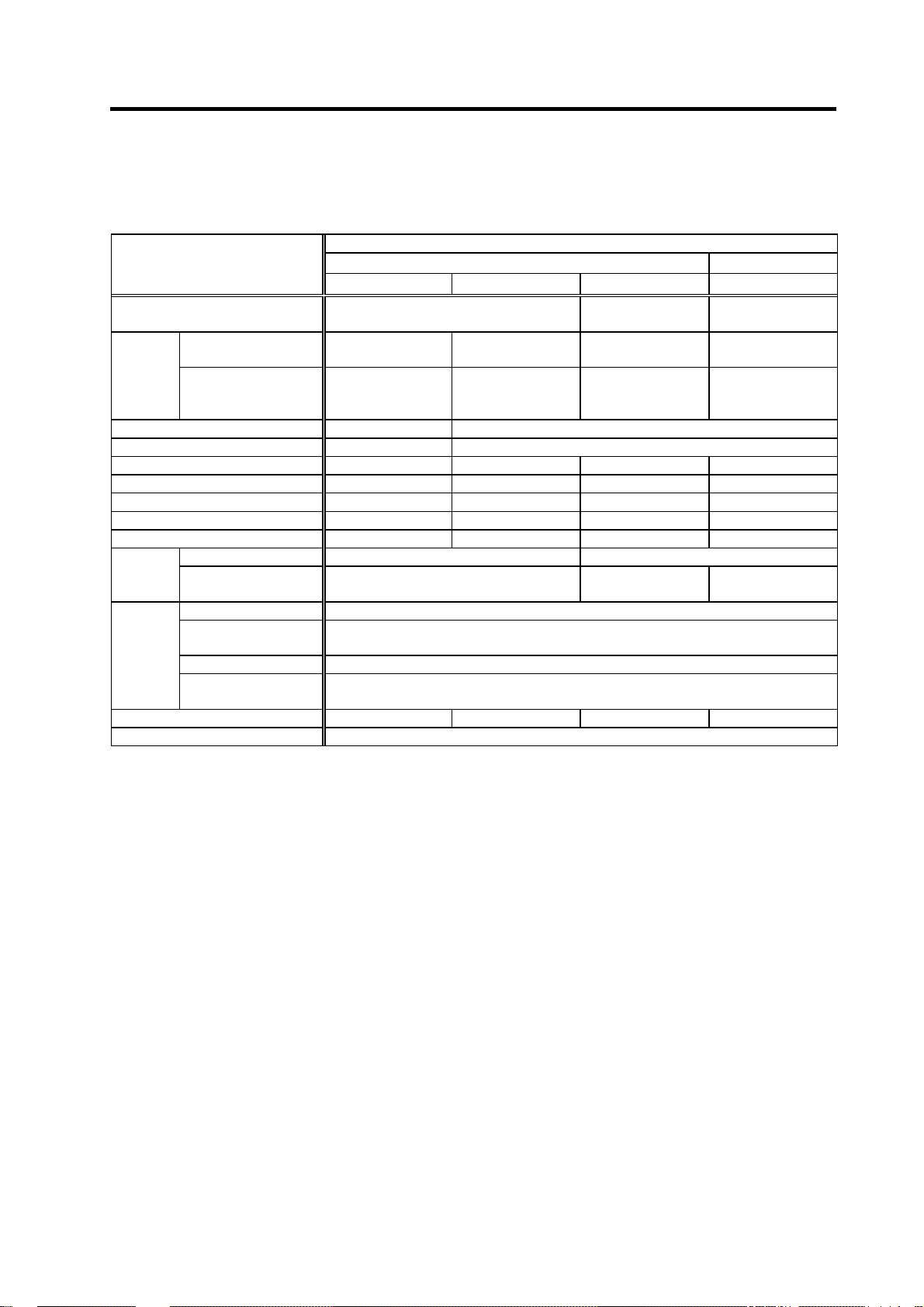
2-2-3 Power supply unit
Power supply
unit type
Rated output [kW] 3.7 5.5 7.5 11.0 15.0 18.5 22.0 26.0 30.0 37.0
Input
Output
Control
power
Main circuit method
Structure
Cooling method
Weight [kg] 3.4 4.6 5.8 6.0 8.3 8.4 8.6 8.8
Heat radiated
at rated output
Noise Less than 55dB
MDS-C1-CV- 37 55 75 110 150 185 220 260 300 370
Rated voltage
Frequency
Rated current
Rated voltage
Rated current
Voltage
Frequency
Current
Rush current [A] MAX.35
Rush
conductivity
time
[V] 200/200 to 230AC
[Hz] 50/60 Frequency fluctuation within ±3%
[A] 16 20 26 35 49 66 81 95 107 121
[V] 270 to 311DC
[A] 17 20 30 41 58 76 95 115 144 164
[V] 200/200 to 230AC
[Hz] 50/60
[A] Max.0.2
[ms] MAX.6
Protection type (Protection method: IP20 [over all] / IP00 [Terminal block TE1])
Self-
Forced wind cooling
cooling
[W] 55 65 80 125 155 195 210 260 320 400
(internal)
Power supply unit MDS-C1-CV Series
Converter with power regeneration circuit
Forced wind cooling (fin)
2 - 17
Page 40

2. Specifications
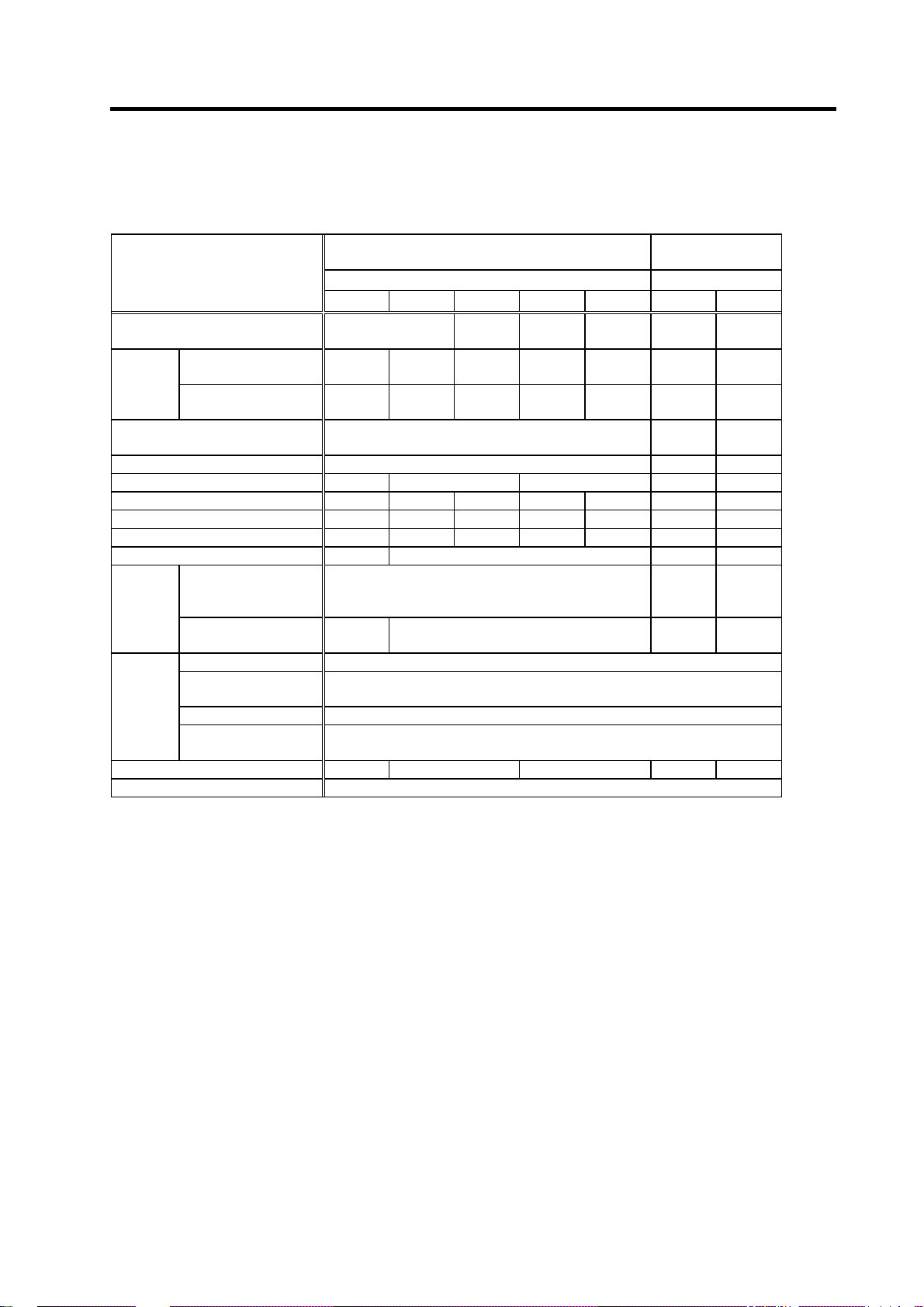
2-2-4 AC reactor
An AC reactor must be installed for each power supply unit.
(1) Specifications
AC reactor type B-AL- 7.5K 11K 18.5K 30K 37K
Compatible
power
supply unit
type
Rated capacity
(30-minute rating)
Rated voltage [V] 200/200 to 230AC
Rated current [A] 27 33 66 110 129
Frequency [Hz] 50/60 Frequency fluctuation within ±3%
Environment
Weight [kg] 3.6 3.0 5.2 6.0 10
MDS-C1-CV-
[kW]
Ambient
temperature
Ambient humidity
Atmosphere
Altitude
Vibration/impact
37,55,75 110 150,185 220,260,300 370
7.5 11 18.5 30 37
Operation: -10 to 60°C (with no freezing),
Storage/Transportation: -10°C to 60°C (with no freezing)
Operation: 80%RH or less (with no dew condensation),
Storage/Transportation: 80%RH or less (with no dew condensation)
With no corrosive gas, inflammable gas, oil mist or dust
Operation/Storage: 1000 meters or less above sea level,
Transportation: 10000 meters or less above sea level
9.8m/s2 (1G) / 98m/s2 (10G)
AC reactor
Indoors (no direct sunlight)
2 - 18
Page 41

2. Specifications
2-2-5 D/A output specifications for spindle drive unit
(1) D/A output specifications
Item Explanation
No. of channels 2ch
Output cycle 444µs (min. value)
Output precision 8bit
Output voltage range
Output magnification
setting
0V to +5V (zero) to +10V,
0V to +10V for meter output
±1/256 to ±128-fold
CN9 connector
Output pin
MO1 = Pin 9
MO2 = Pin 19
GND = Pin 1
Phase current feedback output function
Function
U phase current FB : Pin 7
V phase current FB : Pin 17
(2) Setting the output data
No. Abbrev. Parameter name Explanation
SP253 DA1NO
SP254 DA2NO
No. Output data Or i gi nal data uni t
ch1: Speedometer output
0
ch2: Load meter output
1 –
2 Current command
3 Current feedback
4 Speed feedback
5 –
80 Control input 1
81 Control input 2
82 Control input 3
83 Control input 4
84 Control output 1
85 Control output 2
86 Control output 3
87 Control output 4
D/A output channel 1 data No.
D/A output channel 2 data No.
10V=max. speed (Zero=0V) 0 Depends on maximum speed 3.5ms
10V=120% load (Zero=0V) 0 30-minute rating 12%/V 3.5ms
Rated 100%=4096 8 30-minute rating 20%/V 3.5ms
Rated 100%=4096 8 30-minute rating 20%/V 3.5ms
Input the No. of the data to be output to each D/A output channel.
1deg=(64000÷65536)
r/min 13 500rpm/V 3.5ms
HEX Bit correspondence 3.5ms
Output magnification
standard setting value
(SP255, SP256)
CN9 connector
Pin
Name
LG
1
2
3
4
5
6
7
UIFB
8
MO19
10
Output unit for standard
Pin
11
12
13
14
15
16
17
18
20
Name
VIFB
MO2 19
setting
MDS-C1-SPA
Output
cycle
2 - 19
Page 42

2. Specifications
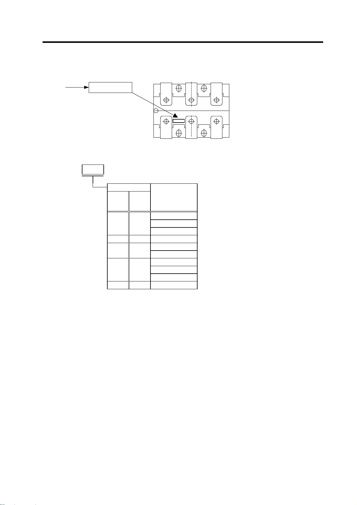
2-2-6 Explanation of each part
(1) Explanation of each spindle drive unit part
<1>
<2>
<3>
<5>
<7>
<9>
<11>
<13>
<4>
<6>
<8>
<10>
<12>
<14>
MDS-C1-SPA
The connector layout differs according to the unit being used. Refer to each unit's outline drawing
for details.
Each part name
Name Description
<1> LED --- Unit status indication LED
SW1,
<2>
<3> CN10 ---
<4> CN11 --- Orient position shift / general-purpose output connector
<5> CN9A --- Personal computer connection / analog output connector
<6> CN4 --- Power supply communication connector
<7> CN5 --- Internal PLG encoder connection connector
<8> CN6 --- Magnetic sensor / external encoder connection connector
<9> CN12 --- Digital speed command / general-purpose output connector
<10>
<11> TE2 L+, L– Converter voltage input terminal (DC input)
<12> TE3 L11, L21 Control power input terminal (single-phase AC input)
<13> TE1 U, V, W Motor power output terminal (3-phase AC output)
<14>
(Note1) For customer switching from MDS-A/B Series
PB1,
PB2,
PB3
Control circuit
CN8A --- Analog speed command / override / pulse output connector
PE
Main circuit
Make sure that PE terminal position has changed from UVW terminal to the bottom of the cooling fan.
---
SW1: Axis No. setting switch
PB1,2,3: Parameter setting button
General-purpose input output / DC power supply connection
connector
Grounding terminal
Screw size
Spindle drive unit MDS-C1-SPA-
Type 04 to 37 55 to 110,150S 150 to 185 220 to 300
Unit width (mm) 60 90 120 150
<11> L+, L– M6 x 14
<12> L11,L21 M4 x 10
<13> U, V, W M4 x 12 M5 x 12 M8 x 14
<14>
M4 x 8 M5 x 12 M8 x 14
2 - 20
Page 43

2. Specifications
(2) Explanation of each power supply unit part
<1>
<3>
<4>
<7>
<10>
<11>
<2>
<5>
<8>
<9>
<6>
MDS-C1-CV Bottom view
The connector layout differs according to the unit being used. Refer to each unit's outline drawing
for details.
Each part name
Name Description
<1> LED --- Power supply status indication LED
<2> SW1 --- Power supply setting switch
<3> CN4 --- Spindle communication connector (master)
<4> CN9 --- Spindle communication connector (slave)
<5> --- CHARGE LAMP TE2 output charging/discharging circuit indication LED
Control circuit
<6>
<7> TE2 L+, L– Converter voltage output terminal (DC output)
<8> L11, L21 Control power input terminal (single-phase AC input)
<9>
<10> TE1 L1, L2, L3 Power input terminal (3-phase AC input)
<11>
(Note1) CN23 is located at the bottom of the power supply unit.
(Note2) For customer switching from MDS-A/B Series
CN23 --- External emergency stop input connector
TE3
Main circuit
PE
Make sure that PE terminal position has changed from UVW terminal to the bottom of the cooling fan.
MC1 External contactor control terminal
Grounding terminal
Screw size
Power supply unit MDS-C1-CV-
Type 37 to 75 110 150 to 185 220 to 370
Unit width (mm) 60 90 120 150
<7> L+, L– M6 x 16
<8> L11, L21 M4 x 10
<9> MC1 M4 x 10
<10> L1, L2, L3 M4 x 10 M5 x 12 M8 x 14
<11>
M4 x 8 M5 x 8 M8 x 14
2 - 21
Page 44

2. Specifications
2-3 Restrictions and precautions
There are restrictions on the layout of spindle drive unit and power supply unit, and on sequence as
follows.
When designing a power distribution box or creating sequence, always consider this section, and satisfy
the following items.
2-3-1 Layout of unit
Arrange the spindle drive unit and power supply unit as follows.
(1) When installing one spindle drive
Spindle
drive
Power
supply
Link bar
(Front)
(2) When installing two spindle drives
1) When the total spindle drive output is 37kW or less
Spindle
drive
Power
supply
(Front)
Spindle
drive
Link bar
2) When the total spindle drive output exceeds 37kW
Spindle
drive
(1)
(Front)
Power
supply
(1)
Spindle
drive
(2)
Link bar
Power
supply
(2)
(Note 1) Install each unit next to each other (vertical direction is not acceptable) with a 3cm or less
clearance between spindle drive unit and power supply unit.
Note that this does not apply to the section between spindle drive (2) and power supply unit (1)
shown in 2) of section (2).
(Note 2) When using section (2) 2), install an ACL (B-AL) on each power supply unit.
2 - 22
Page 45

2
2. Specifications
2-3-2 Precautions for installing multiple power supply units
The methods for installing the two spindles are explained here as an example for installing multiple
power supply units.
NC(PC)
MDS-C1-SPA (No.1) MDS-C1-CV (No.1)
MDS-C1-SPA (No.2)
MDS-C1-CV (No.2)
00VAC
C
N
10
11
12
8A
9A
C
N
4
C
N
4
L1, L2, L3
MC
MC1
L+, L-
L11, L21
C
N
10
11
12
8A
9A
C
N
4
C
N
4
MC1
L+, L-
L11, L21
L1, L2, L3
MC
NFB1(No.1)
AC rector
(B-AL No.1)
Contactor (No.1)
(1) Connecting the L+, L-, L11 and L21 link bars
Connect the L+ and L- link bars independently with C1-CV(No.1) and C1-CV(No.2) as shown above.
Make sure that both C1-CV link bars are not short-circuited when connected.
(2) Connecting and selecting NFB1, contactor and AC reactor
An NFB1, a contactor and an AC reactor must be installed independently to each power supply as
shown above. (These cannot be shared.) Note that the contactor, excluding C1-CV-370, can be
omitted.
(3) Connecting the MC1 terminal (A/B-CV)
When using the contactor, set the C1-CV rotary switch to "0", and when not using, set to "1".
2 - 23
NFB1 (No.2)
AC reactor
(B-AL No.2)
Contactor (No.2)
Page 46

2
A
2. Specifications
2-3-3 Precautions when installing multiple spindle drive units to one power supply unit
The methods for installing two spindle drive units to one power supply unit are explained here as an
example.
NC(PC)
MDS-C1-SPA (No.1) MDS-C1-CV MDS-C1-SPA (No.2)
00VAC
10
11
12
8A
9A
C
N
C
N
4
C
N
4
C
N
9
MC1
L1, L2, L3
MC
C
N
10
11
12
8A
9A
C
N
4
L+, L-
L11, L21
NFB1
C reactor
(B-AL)
Contactor
(1) Connecting C1-CV and C1-SPA
Connect C1-CV CN4 and C1-SPA (No. 1) CN4 to C1-CV CN9 and C1-SPA (No.2) CN4. If C1-SPA is
connected with three or more axes, leave CN4 for C1-SPA (No. 3) and following open.
Note that the C1-CV can be controlled (READY ON/OFF, alarm display, etc.) only by the spindle
drive unit connected to C1-CV CN4.
(2) Make sure that the machine ready complete input turns ON and OFF simultaneously for all the
spindle drive units. Do not allow the signal to turn ON and OFF for only one spindle drive unit.
(3) When turning the machine ready complete input OFF during an emergency stop, always have all the
spindle drive units output the zero speed signal before turning the signal OFF.
(4) If an alarm occurs in one of the spindle drive units, turn OFF the machine ready complete input OFF
for all the spindle drive units.
(5) When connecting three or more spindle drive units, install the large-capacity spindle drive units on
both sides of the power supply unit.
2 - 24
Page 47

3. Characteristics
3-1 Spindle motor.....................................................................................................................................3-2
3-1-1 Environmental conditions............................................................................................................3-2
3-1-2 Shaft characteristics.................................................................................................................... 3-2
3-2 Drive unit characteristics.................................................................................................................... 3-3
3-2-1 Environmental conditions............................................................................................................3-3
3-2-2 Heating value ..............................................................................................................................3-4
3 - 1
Page 48

3. Characteristics
3-1 Spindle motor
3-1-1 Environmental conditions
Environment Conditions
Ambient temperature 0°C to +40°C (with no freezing)
Ambient humidity 90%RH or less (with no dew condensation)
Storage temperature –20°C to +65°C (with no freezing)
Storage humidity 90%RH or less (with no dew condensation)
Atmosphere
Altitude
no corrosive gases, inflammable gases, oil mist or dust
Operation/storage: 1000m or less above sea level
Transportation: 10000m or less above sea level
3-1-2 Shaft characteristics
There is a limit to the load that can be applied on the motor shaft. Make sure that the load applied on the
radial direction, when mounted on the machine, is below the tolerable values given below. These loads
may affect the motor output torque, so consider them when designing the machine.
Spindle motor Tolerable radial load
SJ-V3.7-02ZM 490 N
SJ-V2.2-01, SJ-V3.7-01
SJ-V7.5-03ZM, SJ-V11-06ZM
SJ-V5.5-01, SJ-V11-08ZM
SJ-PMF01830-00
SJ-V7.5-01, SJ-V11-01
SJ-V22-06ZM, SJ-V30-02ZM, SJ-PMF03530-00
SJ-V11-09, SJ-V15-01, SJ-V15-03, SJ-V18.5-01, SJ-V18.5-03
SJ-V22-01, SJ-V22-05, SJ-V26-01, SJ-30A
SJ-22XW5 3920 N
SJ-37BP 4900 N
SJ-22XW8, SJ-45BP
SJ-V55-01
The load point is at the one-half of the shaft length.
Indoors (no direct sunlight);
980 N
1470 N
1960 N
2940 N
5880 N
Radial load
3 - 2
Page 49

3-2 Drive unit characteristics
3-2-1 Environmental conditions
Environment Conditions
Ambient temperature 0°C to +55°C (with no freezing)
Ambient humidity 90%RH or less (with no dew condensation)
Storage temperature –15°C to +70°C (with no freezing)
Storage humidity 90%RH or less (with no dew condensation)
Atmosphere
Altitude
Vibration
(Note) When installing the machine at 1,000m or more above sea level, the heat dissipation
characteristics will drop as the altitude increases. The upper limit of the ambient
temperature drops 1°C with every 100m increase in altitude. (The ambient temperature at
an altitude of 2,000m is between 0 and 45°C.)
3. Characteristics
Indoors (no direct sunlight);
no corrosive gases, inflammable gases, oil mist or dust
Operation/storage: 1000m or less above sea level
Transportation: 10000m or less above sea level
Operation/storage: 4.9m/s
Transportation: 49m/s
2
(0.5G) or less
2
(5G) or less
3 - 3
Page 50

3. Characteristics
3-2-2 Heating value
Each heating value is calculated with the following values.
The values for the spindle drive unit apply for the continuous rated output. The values for the power
supply unit include the AC reactor's heating value.
Servo drive unit Power supply unit
Type
MDS-C1-
SPA- 55 31 76 CV- 37 21 34
SPA- 75 35 102 CV- 55 23 42
SPA-110 41 140 CV- 75 25 55
SPA-150S 48 140 CV-110 26 99
SPA-150 48 187 CV-150 29 126
SPA-185 62 280 CV-185 33 162
SPA-220 65 301 CV-220 35 175
SPA-260 80 403 CV-260 40 220
SPA-300 98 522 CV-300 46 274
Heating
value [W]
Inside
panel
Outside
panel
Type
MDS-C1-
CV-370 54 346
(Note 1) The values for the spindle drive unit are the heating value at the continuous rated output.
(Note 2) The total heating value for the power supply includes the heating value for the AC reactor.
(Note 3) The total heating value for the unit is the total sum of the heating values for the above
corresponding units which are mounted in the actual machine.
Example) When the CV-185, SP-185 units are mounted
Unit total heating value (W) =195+242=437(W)
Heating
value [W]
Inside
panel
Outside
panel
3 - 4
Page 51

4. Dedicated Options
4-1 Orientation option...............................................................................................................................4-2
4-1-1 Magnetic sensor.......................................................................................................................... 4-3
4-1-2 Spindle side detector (OSE-1024-3-15-68, OSE-1024-3-15-68-8)............................................. 4-6
4-2 Cables and connectors ......................................................................................................................4-8
4-2-1 Cable connection diagram ..........................................................................................................4-8
4-2-2 List of cables and connectors...................................................................................................... 4-9
4 - 1
Page 52

p
p
4. Dedicated Options
4-1 Orientation option
Select the orientation option to be required for the spindle control based on the following table.
For each control function, availability of use differs depending on the specifications in the NC side, so
also refer to the manuals of NC side.
(a) No-variable speed control
(When spindle and motor are directly coupled or coupled with a 1:1 gear ratio)
Without orientation option With orientation option
Spindle
control item
Speed
control
Orientation
control
S-analog
high-speed
synchronous
ta
control
(Note 1) { : Control possible
(Note 2) The S-analog high-speed synchronous tap control is an option deferent from orientation. For details, refer to “2-2-2 (2)
Control specifications
Normal cutting control { { {
Constant surface speed
control (lathe)
Thread cutting (lathe) × { {
1-point orientation
control
Multi-point orientation
control
Orientation indexing × × {
Standard synchronous
tap
Synchronous tap after
zero point return
× : Control not possible
Spindle drive unit function specifications list”. Setting position loop in the NC side is required.
Motor PLG
{ { {
× × {
× × {
{ { {
× { {
Motor PLG
with Z-phase
(b) Variable speed control
(When using V-belt, or when spindle and motor are connected with a gear ratio other than 1:1)
Without orientation option With orientation option
Spindle
control item
Speed
control
Orientation
control
S-analog
high-speed
synchronous
ta
control
(Note 1) { : Control possible
(Note 2) The S-analog high-speed synchronous tap control is an option deferent from orientation. For details, refer to “2-2-2 (2)
Control specifications
Normal cutting control { { { { {
Constant surface speed
control (lathe)
Thread cutting (lathe)
1-point orientation
control
Multi-point orientation
control
Orientation indexing
Standard synchronous
tap
Synchronous tap after
zero point return
× : Control not possible
U : Control not possible when using V-belt
S : Control not possible when varying the speed with a method other than the gears and timing belt (when using V- belt
or timing belt).
Spindle drive unit function specifications list”. Setting position loop in the NC side is required.
Motor PLG
U U U U {
× × × × {
× × × { {
× × × × {
× × × × {
S S S S {
× × × S {
Motor PLG
with Z-phase
Motor PLG
with Z-phase
Motor PLG
with Z-phase
Magnetic
sensor
This normally is not used
for no-variable speed control.
Magnetic
sensor
Spindle side
detector
(1020p/rev encoder)
Spindle side
detector
(1020p/rev encoder)
4 - 2
Page 53

4. Dedicated Options
4-1-1 Magnetic sensor
Prepare the magnetic sensor parts with the following types. When purchasing independently, always
prepare with the required configuration part types.
(1) Type
Type Type
Tolerable
speed [r/min]
Standard MAGSENSOR BKO-C1810H01-3 0 to 6000 H01 H02 H03
High-speed standard MAGSENSOR BKO-C1730H01.2.6 0 to 12000 H01 H02 H06
High-speed small MAGSENSOR BKO-C1730H01.2.9 0 to 12000 H01 H02 H09
MAGSENSOR BKO-C1730H01.2.41 0 to 25000 H01 H02 H41
High-speed ring
MAGSENSOR BKO-C1730H01.2.42 0 to 25000 H01 H02 H42
MAGSENSOR BKO-C1730H01.2.43 0 to 30000 H01 H02 H43
MAGSENSOR BKO-C1730H01.2.44 0 to 30000 H01 H02 H44
Independent type
Drive un it Sensor Magne t
(Note) When preparing with independent types, replace the section following the H in the
prepared type with the independent type.
Example: When preparing only the standard magnetic sensor's sensor section, the
type will be MAGSENSOR BKO-C1810H02.
(2) Outline dimension drawing:
z Drive unit H01
2-ø5.5 hole
25
Connector (sensor side)
For BKO-C1810H01, R04-R08F is used.
For BKO-C1730H01, TRC116-21A10-7F is used.
z Sensor H02
Reference
notch
32
14
1
17.5
18
5
5
30
25
25
When using the magnetic sensor, orientation control cannot be carried out with a
CAUTION
machine having a gear ratio between the spindle motor and spindle exceeding
1:31.
4 - 3
Connector (controller cable side)
Unit side (TRC116-21A10-7M)
Cable side (TRC116-12A100-7F10.5)
5.5
Cable length 500
ø6
Connector
For BKO-C1810H02, R04-R-8M is used.
For BKO-C1730H02, TRC116-12A10-7M is used.
+100
-0
20
[Unit: mm]
[Unit: mm]
Page 54

∗
r
z Magnet
Part
No.
Tolerable
speed
4. Dedicated Options
Outline drawings
H03
H06
H09
H41
0 to 6000
r/min
0 to 12000
r/min
0 to 12000
r/min
0 to 25000
r/min
Reference hole
40
50
28
38
4-ø4.3 hole
2.5
7.5
Weight: 40 ± 1.5g
Installation screw: M4
[Unit: mm]
S
N
50
40
30
N.P
Case
1.6
10
2-ø4.3 hole
7
D
E
Cover
Weight: 14.8 ± 0.7g
Installation screw: M4
Spun ring
RINGFEDER
RFN8006 J×K
[Unit: mm]
4-F screw
Stainless case
SUS-303
H42
H43
H44
0 to 25000
r/min
0 to 30000
r/min
0 to 30000
r/min
øB
øA
0.1
±
Gap 1
Sensor head
Reference
notch
[Unit: mm]
Magnet
Dimensions
Model A B C D E F G H
BKO-C1730H41
BKO-C1730H42
105
94
BKO-C1730H43
BKO-C1730H44
78
66
Stop position scale
70H7
+0.030
–0
+0.030
60H7
–0
50H7
+0.025
–0
40H7
+0.025
–0
Polarity (N,S) is indicate d o n th e sid e wall of cover.
Detection head should be installed so that the reference
notch of sensor head comes on the case side.
90 28 19
79 25 17
66 23 15
54 20 13
N
M6×1.0
M5×0.8
M5×0.8
M4×0.7
45°
S
5 90
5 79
5 66
5 54
øC
2-øG±0.15øH
on circumference
J × X
70×79
60×68
50×57
40×45
L
1
1
1
1
Weight
(g)
1024±4
768±4
478±4
322±4
Reference notch
Gap
G hole
h6
Spindle damping screw
Installation of magnet
Spindle
Case
Cove
Cautions on installation of H41 to H44
1. Tolerance to shaft dimension should be "h6" on the
part for installing a magnet.
2. 2-øG hole can be used for positioning of spindle and
magnet.
3. Magnet shall be installed as shown to the left.
4. Misalignment between sensor head and magnetic
center line shall be within ±2mm.
5. There is an NS indication on the side of the cover.
Install so that the reference notch on the sensor
head comes to the case side.
4 - 4
Page 55

(3) Caution on installation of magnet
Observe the following cautions when installing the magnet to the spindle.
(a) Do not place an intense magnetic source near the magnet.
(b) Carefully handle the magnet, avoiding mechanical shock to the magnet.
(c) Secure the magnet to the spindle with M4 screws.
(d) After the magnet is installed, balance the entire spindle.
(e) Align the center of the magnet with the center line of the rotating disk on the spindle. (For the
position relation, refer to the maintenance instruction manual.)
(f) Keep the magnet and its peripheral clean avoiding iron particles and cutting chips from adhering
to the magnet. Failure to observe this could result in malfunction.
(g) Apply lock paint, or other suitable means, to prevent installation screws from becoming loose.
(h) If the magnet is installed on a ground rotating disk, demagnetize the disk because the rotating
disk is thought to be magnetized.
(i) Diameter of rotating disk on which the magnet is installed should be within the range from 80mm
to 120mm. If this range is exceeded, the magnet may be damaged and the orient control may
not be carried out correctly although the speed is below the tolerable speed of the magnet.
(j) If rotation speed of the spindle on which the magnet is installed exceeds 6,000r/min, use a
high-speed type magnet (applicable up to 12,000r/min of rotation speed). If rotation speed
exceeds 12,000r/min, use a ring type magnet.
(k) When installing the magnet on a rotating body plane, keep the speed below 6,000r/min.
(4) Caution on installation of sensor
Observe the following cautions when installing the sensor.
4. Dedicated Options
(a) The center line of head should be in line with the center of magnet.
(b) Connector used in preamplifier
BKO-C1810 : Oil proof-type
BKO-C1730 : Not oil proof-type
Install both type at a place not subject to oil.
(c) The cable between the preamplifier and the controller should be laid down apart from
high-voltage cables.
(d) Check the connector wiring, securely engage the receptacle and tighten connector lock screws.
4 - 5
Page 56

4. Dedicated Options
4-1-2 Spindle side detector (OSE-1024-3-15-68, OSE-1024-3-15-68-8)
When a spindle and motor are connected with a V-belt, or connected with a gear ratio other than 1:1,
use this spindle side detector (1024p/rev encoder) to detect the position and speed of the spindle. Also
use this detector when orientation control and synchronous tap control, etc are executed under the
above conditions.
(2) Specifications
Detector type OSE-1024-3-15-68 OSE-1024-3-15-68-8
Mechanical
characteristics
for rotation
Mechanical
configuration
Working
environment
(2) Detection signals
Pin Function Pin Function
A A phase K 0V
B Z phase L C B phase M D - N
E Case earth P
F - R
G - S -
H +5V
J -
Inertia 0.1 × 10⁻⁴kgm2 or less 0.1 × 10⁻⁴kgm2 or less
Shaft friction torque 0.98Nm or less 0.98Nm or less
Shaft angle acceleration 104 rad/s2 or less 104 rad/s2 or less
Tolerable continuous rotation speed 6000 r/min 8000 r/min
Maximum rotation speed 7030 r/min 8030 r/min
Bearing maximum non-lubrication
time
Shaft amplitude
(position 15mm from end)
Tolerable load
(thrust direction/radial direction)
Weight 1.5kg 1.5kg
Squareness of flange to shaft 0.05mm or less
Flange matching eccentricity 0.05mm or less
Ambient temperature range –5°C to +55°C
Storage temperature range –20°C to +85°C
Humidity 95%Ph
Vibration resistance 5 to 50Hz, total vibration width 1.5mm, each shaft for 30min.
Impact resistance 294.20m/s
Signal name Number of detection pulses
A, B phase 1024p/rev
Z phase 1p/rev
20000h/6000r/min 20000h/8000r/min
0.02mm or less 0.02mm or less
10kg/20kg
Half of value during operation
Half of value during operation
2
10kg/20kg
(30G)
Connector pin layout
T -
A phase
Z phase
B phase
4 - 6
Page 57

(3) Outline dimension drawings
4. Dedicated Options
102 33
68
68
Ø
MS3102A20-29P
3 2
0
-0.11
-0.006
1.15
-0.017
15
Ø
+0.14
0
2
14.3
Ø
20
16
Ø
-0.009
50
Ø
-0.025
50
Ø
4- Ø5.4 hole
+0.012
5
0
Shaft section
+0.05
0
3
56
Key way magnified figure
Spindle side detector (OSE-1024-3-15-68, OSE-1024-3-15-68-8)
[Unit: mm]
4 - 7
Page 58

4. Dedicated Options
4-2 Cables and connectors
4-2-1 Cable connection diagram
The cable connected with CN4, CN5 or CN6 of spindle drive unit in the following diagram can be
ordered from Mitsubishi Electric Corp. as option parts. Cables can only be ordered in the designated
lengths. If a cable connected with the other connector or a cable with special length is required,
purchase a connector or connector set, etc., and create the cable.
NC
PC
DIO
Meter
Personal
computer
Spindle drive unit
(MDS -C1-SPA)
CN4
CN5
(2) Spindle detector cable
<Spindle side detector (1024p/rev encoder)
/magnetic sensor cable>
(1)
CN6
Spindle side detector/m agnetic sensor
Power supply unit
(MDS -C1-CV)
(1)
Spin dle motor
(2) Spindle detector cable
<M o to r PLG / Spindle P L G cable>
4 - 8
Page 59

4. Dedicated Options
4-2-2 List of cables and connectors
(1) NC bus cable and connector
(cable and connector between drive unit and power supply unit )
Item Model Contents
For
CN4
For
CN4
NC bus cable
NC bus cable connector set
(Note) The connector manufacturer is subject to change without notice.
SH21
Length:
0.35, 0.5, 0.7, 1,
1.5, 2, 2.5, 3,
3.5, 4, 4.5, 5,
6, 7, 8, 9,
10, 15, 20, 30 m
FCUA-CS000 Drive unit side connector
Drive unit side connector
(3M)
Connector
Shell kit
(3M)
Connector
Shell kit
: 10120-6000EL
: 10320-3210-000
: 10120-3000VE
: 10320-52F0-008
Drive unit side connector
(3M)
Connector
Shell kit
Drive unit side connector
(3M)
Connector
Shell kit
: 10120-6000EL
: 10320-3210-000
: 10120-3000VE
: 10320-52F0-008
4 - 9
Page 60

A
A
A
(2) Spindle detector cable
Item Model Contents
For CN5 Motor PLG cable
For CN6
Magnetic sensor cable
4. Dedicated Options
CNP5-
Connector type
2: Connector
E: Crimped terminal
xis No. (1 to 8 axis)
1: No. 1 axis
to
8: No. 8 axis
System No.
None : 1st system
2 : 2nd system
P : PLC axis
Length:
2, 5, 10, 20, 30 m
CNP6M-
Connector type
2: Connector
E: Crimped terminal
xis No. (1 to 8 axis)
1: No. 1 axis
to
8: No. 8 axis
System No.
None : 1st system
2 : 2nd system
P : PLC axis
-
-
Spindle drive unit side
connector (3M)
Connector
Shell kit
Spindle drive unit side
connector (3M)
Connector
Shell kit
: 10120-3000VE
: 10320-52F0-008
: 10120-3000VE
: 10320-52F0-008
Spindle motor side connector
For 2-type
(Tyco Electronics AMP)
: 350720-1
Plug
Pin
: 350689-1
For E-type (J.S.T.)
Crimped terminal: V1.25-4
2-type
E-type
Magnetic sensor side
connector
For 2-type (Tajimi Musen)
Plug: TRC116-12A10-7F10.5
For E-type (J.S.T.)
Crimped terminal: V1.25-4
2-type
E-type
Length:
2, 5, 10, 20, 30 m
Spindle side detector (1024p/rev encoder)
cable
CNP6A -
Connector type
2: Straight cannon
3: Angle cannon
E: Crimped terminal
xis No. (1 to 8 axis)
1: No. 1 axis
to
8: No. 8 axis
System No.
None : 1st system
2 : 2nd system
P : PLC axis
Length:
2, 5, 10, 20, 30 m
-
(Note) The connector manufacturer is subject to change without notice.
Spindle drive unit side
connector (3M)
Connector
Shell kit
: 10120-3000VE
: 10320-52F0-008
Spindle side detector
(1024p/rev encoder) side
connector
For 2-type (DDK)
Plug : MS3106A20-29S
Clamp
: MS3057-12A
For 3-type (DDK)
Plug
: MS3108A20-29S
: MS3057-12A
Clamp
For E-type (J.S.T.)
Crimped terminal: V1.25-4
2-type
3-type
E-type
4 - 10
Page 61

(3) External connection cable
Cables shown below are made by the user.
Item Model Contents
For
CN10,
CN11,
CN12
DIO cable
4. Dedicated Options
Spindle drive unit side
connector (3M)
Connector : 10120-3000VE
Shell kit : 10320-52F0-008
Cable: Batch vinyl
External device
NC device
Programmable controller
External part DIO
shield cable
0.2SQ x 20-core (Maximum diameter 12mm or less)
For
CN8A
For
CN9A
Analog speed command input
pulse feedback cable
For meter output
Personal computer
for parameter input
• monitor
Spindle drive unit side
connector (3M)
Connector : 10120-3000VE
Shell kit : 10320-52F0-008
Cable: Twisted pair shield cable
0.3SQ x 4 + 0.3SQ x 3
Spindle drive unit side
connector (3M)
Connector : 10120-3000VE
Shell kit : 10320-52F0-008
Cable: Twisted pair cable
0.3SQ x 2 + 0.3SQ x 2
External device
NC device
Programmable controller
External device
Speed meter
Load meter
Personal computer
(Note1) The connector manufacturer is subject to change without notice.
(Note2) Keep the length of the cables, excluding the cable for CN9A, which is connected with a personal computer, to 30m or less.
(The cable connected with a personal computer must be 3m or less.)
(Note3) Do not relay the CNP5, CNP6M or CNP6A cables. Malfunctions may occur due to noise from the motor drive wire or other
cables. (Orientation position could dislocate, vibration could occur, etc.)
If the cable must be relayed, keep the peeled shield section as short as possible (3cm or less), and separate the cable
from the other drive wires and cables. Mitsubishi will not be held liable for any problems that should occur as a result of a
relayed cable. The customer is responsible for providing measures against noise.
4 - 11
Page 62

5. Peripheral Devices
5-1 Selection of wire................................................................................................................................. 5-2
5-1-1 Example of wires by unit .............................................................................................................5-2
5-2 Selection the AC reactor, contactor and no-fuse breaker..................................................................5-4
5-2-1 Standard selection....................................................................................................................... 5-4
5-2-2 Selection of contactor for changing over spindle motor drive wire .............................................5-5
5-3 Earth leakage breaker........................................................................................................................5-6
5-4 Branch-circuit protection ....................................................................................................................5-7
5-4-1 Circuit protector...........................................................................................................................5-7
5-4-2 Fuse protection............................................................................................................................ 5-7
5-5 Noise filter ..........................................................................................................................................5-8
5-6 Surge absorber ..................................................................................................................................5-9
5-7 Speedometer and load meter...........................................................................................................5-10
5-8 Cable for peripheral control..............................................................................................................5-11
5-8-1 Cable for external emergency stop...........................................................................................5-11
5 - 1
Page 63

5. Peripheral Devices
5-1 Selection of wire
5-1-1 Example of wires by unit
Selected wires must be able to tolerate rated current of the unit’s terminal to which the wire is
connected.
How to calculate tolerable current of an insulated wire or cable is shown in “Tolerable current of electric
cable” (1) of Japanese Cable Makers’ Association Standard (JCS)-168-E (1995), its electric equipment
technical standards or JEAC regulates tolerable current, etc. wire.
When exporting wires, select them according to the related standards of the country or area to export.
In the UL standards, certification conditions are to use wires of 60
Wire’s tolerable current is different depending on conditions such as its material, structure, ambient
temperature, etc. Check the tolerable current described in the specification of the wire to use.
Example of wire selections according to each standard is as follows.
(1) 600V vinyl insulated wire (IV wire) 60
o
C product
(Example according to IEC/EN60204-1, UL508C)
TE1
(L1, L2, L3, )
mm2 AWG mm2 AWG mm2 AWG
3.5 12
3.5 12
5.5 10
14 6
22 4
30 3
38 2
50 60 -
- -
3.5 12
5.5 10
8 8
14 6
22 4
30 3
38 2
60 -
Unit type
Power supply
unit
Spindle drive
unit
Terminal
name
MDS-C1-CV-37
MDS-C1-CV-55
MDS-C1-CV-75
MDS-C1-CV-110
MDS-C1-CV-150
MDS-C1-CV-185
MDS-C1-CV-220
MDS-C1-CV-260
MDS-C1-CV-300
MDS-C1-CV-370
MDS-C1-SPA-55
MDS-C1-SPA-75
MDS-C1-SPA-110
MDS-C1-SPA-150
MDS-C1-SPA-185
MDS-C1-SPA-220
MDS-C1-SPA-260
MDS-C1-SPA-300
(2) 600V double (heat proof) vinyl insulated wire (HIV wire) 75
(Example according to IEC/EN60204-1, UL508C)
TE1
(L1, L2, L3, )
mm2 AWG mm2 AWG mm2 AWG
2 14
3.5 12
5.5 10
14 6
14 6
22 4
30 3
38 2
38 2
50 -
2 14
3.5 12
5.5 10
14 6
14 6
22 4
30 3
38 2
Unit type
Power supply
unit
Spindle drive
unit
Terminal
name
MDS-C1-CV-37
MDS-C1-CV-55
MDS-C1-CV-75
MDS-C1-CV-110
MDS-C1-CV-150
MDS-C1-CV-185
MDS-C1-CV-220
MDS-C1-CV-260
MDS-C1-CV-300
MDS-C1-CV-370
MDS-C1-SPA-55
MDS-C1-SPA-75
MDS-C1-SPA-110
MDS-C1-SPA-150
MDS-C1-SPA-185
MDS-C1-SPA-220
MDS-C1-SPA-260
MDS-C1-SPA-300
o
C and 75 oC product. (UL508C)
TE2
(L+, L-)
Same as TE1
Match with TE2 of
selected power supply
selected power supply
unit
o
C product
TE2
(L+, L-)
Same as TE1
Match with TE2 of
unit
(L11, L21, L12, L22, MC1)
TE3
1.25 to 2 16 to 14
1.25 to 2 16 to 14
TE3
(L11, L21, L12, L22, MC1)
1.25 to 2 16 to 14
1.25 to 2 16 to 14
5 - 2
Page 64

5. Peripheral Devices
(3) 600V bridge polyethylene insulated wire (IC) 105oC product
(Example according to JEAC8001)
TE1
(L1, L2, L3, )
mm2 AWG mm2 AWG mm2 AWG
2 14 2 14
2 14 3.5 12
3.5 12 3.5 12
5.5 10 14 6
8 8 14 6
14 6 22 4
14 6 22 4
22 4 30 3
38 2 38 2
38 2 50 -
2 14
3.5 12
5.5 10
14 6
14 6
22 4
30 3
38 2
selected power supply
Unit type
Power supply
unit
Spindle drive
unit
Terminal
name
MDS-C1-CV-37
MDS-C1-CV-55
MDS-C1-CV-75
MDS-C1-CV-110
MDS-C1-CV-150
MDS-C1-CV-185
MDS-C1-CV-220
MDS-C1-CV-260
MDS-C1-CV-300
MDS-C1-CV-370
MDS-C1-SPA-55
MDS-C1-SPA-75
MDS-C1-SPA-110
MDS-C1-SPA-150
MDS-C1-SPA-185
MDS-C1-SPA-220
MDS-C1-SPA-260
MDS-C1-SPA-300
1. Selection conditions follow IEC/EN60204-1, UL508C, JEAC8001.
• Ambient temperature is maximum 40°C.
• Cable installed on walls without ducts or conduits.
To use the wire under conditions other than above, check the standards you
CAUTION
are supposed to follow.
2. The maximum wiring length to the motor is 30m.
If the wiring distance between the drive unit and motor is 20m or longer, use a
thick wire so that the cable voltage drop is 2% or less.
3. Always wire the grounding wire.
TE2
(L+, L-)
Match with TE2 of
unit
(L11, L21, L12, L22, MC1)
TE3
1.25 to 2 16 to 14
1.25 to 2 16 to 14
5 - 3
Page 65

5. Peripheral Devices
5-2 Selection the AC reactor, contactor and no-fuse breaker
5-2-1 Standard selection
Install an AC reactor, contactor and no-fuse breaker (NFB) per one power supply unit. Refer to the table
below and select them according to each power supply unit capacity.
Selection of AC reactor, contactor and no-fuse breaker (NFB)
Power supply unit
capacity
AC reactor B-AL-7.5K B-AL-11K B-AL-18.5K B-AL-30K B-AL-37K
Recommended
contactor
(Special order part)
Recommended
main circuit NFB
(Special order part)
Recommended
motor fan NFB
(Special order part)
3.7 to 7.5kW 11kW 15 to 18.5kW 22 to 30kW 37kW
S-N25 200V S-N35 200V S-N50 200V S-N80 200V S-N150 200V
NF50CS3P-40A0
5
An NFB or CP (circuit protector) can be used as the motor fan breaker.
Select the NFB or CP using a value approximately double the motor fan rated current value shown below.
Contact the NFB or CP manufacturer for details on the recommended wire size, etc.
Spindle motor
frame size
Motor fan
rated current
* A rush current that is approximately double the above rated current flows when the motor starts.
NF50CS3P-50A05 NF100CS3P-100A05 NF225CS3P-150A05 NF225CS3P-175A05
71 90 112 132 160 180
0.1A 0.2A 0.2A 0.2A 0.6A 0.6A
(Note 1) In the above table, a special order part refers to a part that cannot be ordered from Mitsubishi,
and which must be prepared by the user.
(Note 2) To comply with the EC Directives, use contactors and NFB that comply with the EN/IEC
Standards.
If a breaker is shared by several power supply units, the breaker may not
CAUTION
activate when a short-circuit fault occurs in a small capacity unit. This is
dangerous, so never share the breakers.
5 - 4
Page 66

5. Peripheral Devices
5-2-2 Selection of contactor for changing over spindle motor drive wire
When using coil changeover motor and 1-drive unit 2-motor changeover function, select a contactor for
changing over motor drive wire from the table below according to the capacity of spindle drive unit to be
used.
Spindle drive unit type Recommended contactor type
MDS-A/B-SPA(H)-04
MDS-A/B-SPA(H)-075
MDS-A/B-SPA(H)-15
MDS-A/B-SPA(H)-22
MDS-A/B-SPA(H)-37
MDS-A/B/C1-SPA(H)-55
MDS-A/B/C1-SPA(H)-75
MDS-A/B/C1-SPA(H)-110
MDS-A/B/C1-SPA(H)-150
MDS-A/B/C1-SPA(H)-185
MDS-A/B/C1-SPA(H)-220
MDS-A/B/C1-SPA(H)-260
MDS-A/B/C1-SPA(H)-300
MDS-B-SPA(H)-370
MDS-B-SPA(H)-450
MDS-B-SPA(H)-550
(Note 1) These contactors are prepared by the user.
(Note 2) Use the EN/IEC Standards compliant parts in compliance with EC Directives.
S-N10
S-N10
S-N10
S-N10
S-N18
S-N20
S-N25
S-N35
S-N50
S-N65
S-N80
S-N80
S-N125
S-N150
S-N180
S-N300
5 - 5
Page 67

5. Peripheral Devices
5-3 Earth leakage breaker
When installing an earth leakage breaker, select the breaker on the following basis to prevent the
breaker from malfunctioning by the higher frequency earth leakage current generated in the spindle
drive unit.
(1) Selection
Obtaining the earth leakage current for all drive units referring to the following table, select an earth
leakage breaker within the “rated non-operation sensitivity current”.
Usually use an earth leakage breaker for inverter products that function at a leakage current within
the commercial frequency range (50 to 60Hz).
If a product sensitive to higher frequencies is used, the breaker could malfunction at a level less
than the maximum earth leakage current value.
Unit Earth leakage current Maximum earth leakage current
MDS-C1-SPA-55 to 300 6mA 15mA
(Note1) Maximum earth leakage current: Value that considers wiring length and grounding, etc.
(Commercial frequency 50/60Hz)
(Note2) The earth leakage current in the power supply unit side is included in the drive unit side.
(2) Measurement of earth leakage current
When actually measuring the earth leakage current, use a product that is not easily affected by the
higher frequency earth leakage current. The measurement range should be 50 to 60Hz.
Earth leakage current for each unit
1. The earth leakage current tends to increase as the motor capacity increases.
2. A higher frequency earth leakage current will always be generated because the
inverter circuit in the drive unit switches the transistor at high speed. Always
POINT
ground to reduce the higher frequency earth leakage current as much as
possible.
3. An earth leakage current containing higher frequency may reach approx.
several hundreds of mA. According to IEC479-2, this level is not hazardous to
the human body.
5 - 6
Page 68

r
5. Peripheral Devices
5-4 Branch-circuit protection
5-4-1 Circuit protector
This breaker is used to switch the control power and to provide overload and short-circuit protection.
When connecting a circuit protector or breaker to the power input (TE3 terminals L11 and L21) for the
control circuit, use a product that does not trip (incorrectly activate) by a rush current when the power is
turned ON. A circuit protector with inertial delay and an operation delayed type breaker are available to
prevent unnecessary tripping. Select the product to be used according to the machine specifications.
The rush current and rush conductivity time differ according to the power impedance and power ON
timing, so select a product that does not trip even under the conditions listed in the following table.
Rush current: Ip=35
POINT
I [A]
Rush conductivity time:
Time to reach 36.8% of rush current; equivalent to breake
operation characteristics operation time.
36.8%
t [ms]
Time constant: T=6
When collectively protecting the control circuit power for multiple units, select a
circuit protector or breaker that satisfies the total sum of the rush current Ip.
The largest value is used for the rush conductivity time T.
5-4-2 Fuse protection
The fuse of branch-circuit protection must use UL class CC, J or T. In the selection, please consider
rush current and rush conductive time.
Selection of branch-circuit protection fuse
Connected total of unit
1 – 4
5 – 8
Rated [V] Current [A] AWG
Fuse (Class CC) Wire Size
600
20
35
16 to 14
For continued protection against risk of fire, replace only with same type 600
CAUTION
V, 20 or 35 A (UL CLASS CC) fuse.
5 - 7
Page 69

5-5 Noise filter
(1) Selection
Use an EMC noise filter if the noise conducted to the power line must be reduced. Select an EMC
noise filter taking the power supply unit's input rated voltage and input rated current into
consideration.
(2) Noise filter mounting position
Install the noise filter to the power supply unit’s power input as the diagram below indicates.
Power
distribution panel
Breaker
Power
supply
5. Peripheral Devices
AC reactor
Noise filter
Contactor
Power supply unit
R
S
T
MDS-C1-CV
(Note) The noise filter must be prepared by the user.
Recommended devices: Okaya Electric Industries 3SUP-HL-ER-6B Series
Soshin Electric HF3000C-TMA Series
Contact: Okaya Electric Industries Co., Ltd. Telephone: 03-3424-8120
(+81-3-3424-8120)
http://www.okayaelec.co.jp
Soshin Electric Co., Ltd. Telephone: 03-3775-9112
(+81-3-3775-9112)
http://www.soshin.co.jp
(Note) The above devices may be changed at the manufacturer's discretion.
Contact each manufacturer for more information.
5 - 8
Page 70

5. Peripheral Devices
5-6 Surge absorber
When controlling a magnetic brake of a servomotor in DC OFF circuit, a surge absorber must be
installed to protect the relay contacts and brakes. Commonly a varistor is used.
(1) Selection of varistor
When a varistor is installed in parallel with the coil, the surge voltage can be adsorbed as heat to
protect a circuit. Commonly a 120V product is applied. When the brake operation time is delayed,
use a 220V product. Always confirm the operation with an actual machine.
(2) Specifications
Select a varistor with the following or equivalent specifications. To prevent short-circuiting, attach a
flame resistant insulation tube, etc., onto the leads as shown in the following outline dimension
drawing.
Varistor specifications
(A)
Rating
Energy
withstand level
(J)
Power
Max. limit
voltage
Varistor
voltage
Varistor type
ERZV10D121
TNR10V121K
ERZV10D221
TNR10V221K
(Note 1) Selection condition: When ON/OFF frequency is 10 times/min or less, and exciting current is 2A or less
(Note 2) ERZV10D121 and ERZV10D221 are manufactured by Matsushita Electric Industrial Co., Ltd.
TNR10V121K and TNR10V221K are manufactured by MARCON Electronics Co., Ltd.
Contact: Matsushita Electronic Components Co., Ltd : http://www.panasonic.co.jp/ maco/
rating
(range)
(V) AC (V) DC (V) 1 time 2 times 10/1000us 2ms (W) (V) (pF)
120
(108 to 132)
220
(198 to 242)
MARCON Electronics Co., Ltd. Telephone : (Kanto)03-3471-7041 (+81-3-3471-7041)
(Kinki) 06-6364-2381 (+81-3-6364-2381)
(Chubu) 052-581-2595 (+81-52-581-2595)
Tolerable
circuit voltage
75 100 3500 2500 20 14.5 0.4 200 1400
140 180 3500 2500 39 27.5 0.4 360 410
Surge current
withstand level
(3) Outline dimension drawing
• ERZV10D121, ERZV10D221
11.5
[Unit: mm]
20.0
Insulation tube
Normally use a product with 120V varistor voltage. If there is no allowance for the brake
POINT
operation time, use the 220V product. A varistor whose voltage exceeds 220V cannot be
used, as such varistor will exceed the specifications of the relay in the unit.
Electrostatic
capacity
(reference
value)
5 - 9
Page 71

)
p
y
)
p
p
y
(
)
r
30-mi
g
5. Peripheral Devices
5-7 Speedometer and load meter
Speedometer and load meter can be output from the D/A output which is for measuring control data.
(1) Speedometer output
When speedometer is output, +10V DC is output at the motor’s maximum speed regardless of the
motor’s rotation direction. The following specifications are recommended for the display.
(a) Type YM-8G type DC voltage type (Mitsubishi)
(b) Rating 10VDC full scale
(c) Internal impedance approx. 10kΩ
(2) Load meter output
The load meter indicates the percentage of the load in respect to the motor's rated output. The
relation of the motor output capacity [kW] and load meter display [%] is as follows.
kW
acit
ut ca
Motor out
The following specifications are recommended for the display.
(a) Type YM-8G type DC voltage type (Mitsubishi)
(b) Rating 10VDC full scale
(c) Internal impedance approx. 10kΩ
(d) Scale indicating alarm at 100% or above (see right figure)
Overload (for one minute)
zone
50%ED (15-minute)
(30-minute) zone
Continuous rating zone
0 1500 6000 8000
Motor rotation speed (r/min
Load meter output specification
0
10
0
MO1out put voltage (V)
S
eedometer output specification
Load meter 120%
Load meter 100%
Load mete
40
20
Load meter displa
Maximum rotation speed
Motor rotation speed (r/min
Continuous ratin
X 100%
nute rating
60
80
%
100
Red zone
120
5 - 10
Page 72

5. Peripheral Devices
5-8 Cable for peripheral control
5-8-1 Cable for external emergency stop
Prepare the cable below for external emergency stop function (dual emergency stop function). The
cable for external emergency stop must be prepared by the user.
Bottom view of MDS-C1-CV
No. Item Type Manufacturer
101 Connector 2-178288-3 Tyco Electronics AMP
102 Contact 1-175218-2 Tyco Electronics AMP
101 102
External emergency
stop connector
Wire size:0.5 to 1.25SQ
3
1
CN23
Drive unit side
5 - 11
+
-
Page 73

Appendix 1. Outline Dimension Drawings
Appendix 1-1 Outline dimension drawings of spindle motor..................................................................A1-2
Appendix 1-1-1 SJ Series...................................................................................................................A1-2
Appendix 1-1-2 SJ-V Series .................................................................................................... ...........A1-5
Appendix 1-1-3 SJ-VS Series...........................................................................................................A1-15
Appendix 1-2 Unit outline dimension drawings....................................................................................A1-17
Appendix 1-2-1 Spindle drive unit.....................................................................................................A1-17
Appendix 1-2-2 Power supply unit....................................................................................................A1-21
Appendix 1-2-3 AC rector.................................................................................................................A1-25
A1 - 1
Page 74

Appendix 1. Outline Dimension Drawings
Appendix 1-1 Outline dimension drawings of spindle motor
Appendix 1-1-1 SJ Series
• SJ-30A with standard flange
740
850
665.5
60
Cooling air inlet
110
5
110
90
A
A
20
10.5
4
3
8
189
φ
0
0
3
3
φ
2
5
5
3
Terminal box
φ51
Exhaust air
Cooling fan
77 310
4-φ19
°
16
AA
55m6
Cross sectio n
A-A
(Note 1) Provide a clearance of 30mm or more between the cooling fan and wall.
(Note 2) The shaft can also be mounted upward.
(Note 3) If the suspension bolts are removed during operation, plug the screw holes with bolts.
• SJ-30A with standard legs
Terminal box
850
345
Exhaust air
Cooling fan
505
430.5
230
127127
304
110
A
A
10.590
Cooling
air inlet
4-Ø15
16
189
55108
127127
310
[Unit: mm]
63126
55m6
A
Cross section
(Note 1) Provide a clearance of 30mm or more between the cooling fan and wall.
(Note 2) If the suspension bolts are removed during operation, plug the screw holes with bolts.
A1 - 2
A
A-A
[Unit: mm]
Page 75

Appendix 1. Outline Dimension Drawings
• SJ-37BP, SJ-22XW5 with standard flange
Terminal box
909
769
701.5
530
φ51
Exhaust air
Cooling fan
568
A
A
Cooling air inlet
140
140
110
25
15
7
350
224
φ
0
5
3
3
φ
5
0
9
18
7
4-φ19
7
5
°
5
3
AA
60m6
Cross section
A-A
(Note 1) Provide a clearance of 30mm or more between the cooling fan and wall.
(Note 2) The shaft can also be mounted upward.
(Note 3) If the suspension bolts are removed during operation, plug the screw holes with bolts.
• SJ-37BP, SJ-22XW5 with standard legs
Terminal box
508.5 247.5 140
441
Exhaust air
Cooling fan
909
338
400.5
121139.5139.5
6 6352
224
15110
A
A
Cooling
air inlet
70
139.5 139.5
350
18
[Unit: mm]
AA
60m6
Cross section
A-A
[Unit: mm]
(Note 1) Provide a clearance of 30mm or more between the cooling fan and wall.
(Note 2) If the suspension bolts are removed during operation, plug the screw holes with bolts.
A1 - 3
Page 76

r
Appendix 1. Outline Dimension Drawings
• SJ-45BP, SJ-22XW8 with standard flange
Terminal box
Exhaust ai
φ63
Cooling fan
932
792
733
73
Cooling air inlet
140
30
5
140
110
A
A
77 378
278
15
5
8
1
φ
φ
0
0
4
4
2
5
5
3
18
4-φ19
°
φ425
60m6
A-A
A
A
Cross section
(Note 1) Provide a clearance of 30mm or more between the cooling fan and wall.
(Note 2) The shaft can also be mounted upward.
(Note 3) If the suspension bolts are removed during operation, plug the screw holes with bolts.
• SJ-45BP, SJ-22XW8 with standard legs
Terminal box
506.5 272.5 140
447.5
φ63
Exhaust air
Cooling fan
932
385
425.5
133152.5152.5
6 6380
15110
A
A
Cooling
air inle t
4-φ19
85
159 159
278
400
18
[Unit: mm]
AA
60m6
Cross section
A-A
[Unit: mm]
(Note 1) Provide a clearance of 30mm or more between the cooling fan and wall.
(Note 2) If the suspension bolts are removed during operation, plug the screw holes with bolts.
A1 - 4
Page 77

Appendix 1. Outline Dimension Drawings
Appendix 1-1-2 SJ-V Series
• SJ-V2.2-01, SJ-V3.7-02ZM with standard flange
φ35
Terminal box
Exhaust air
Cooling fan
360
300
265
60
130
45
A
A
Cooling air inlet
12
548
8
A
Cross section
16
A-A
8
φ28j6
A
2-M6
φ
5 5
Screw
(Note 1) Provide a clearance of 30mm or more between the cooling fan and wall.
(Note 2) The shaft can also be mounted upward.
(Note 3) If the suspension bolts are removed during operation, plug the screw holes with bolts.
• SJ-V2.2-01, SJ-V3.7-02ZM with standard legs
φ35
8
1
Flange
□174
168
5
□176
φ
1
9
0
φ
2
2
0
[Unit: mm]
4-φ12
Terminal box
Exhaust air
Cooling fan
300
360
265
130
75
105 41
60
45 8
A
A
56
16
A
Cross section
A-A
Cooling
air inlet
8
φ28j6
A
4-φ10
2-M6
Screw
176
168
35
70 70
180
55
(Note 1) Provide a clearance of 30mm or more between the cooling fan and wall.
(Note 2) The shaft can also be mounted upward.
(Note 3) If the suspension bolts are removed during operation, plug the screw holes with bolts.
[Unit: mm]
A1 - 5
Page 78

• SJ-V3.7-01 with standard flange
φ35
Terminal box
Exhaust air
Cooling fan
Appendix 1. Outline Dimension Drawings
390
330
295
160
Cooling air inlet
60
12
5
48
845
A
A
8
Flange
□174
168
φ
5
8
1
1
□176
9
0
φ
5 5
4-φ12
φ
2
2
0
Screw
2-M6
16
φ28j6
AA
Cross section
A-A
(Note 1) Provide a clearance of 30mm or more between the cooling fan and wall.
(Note 2) The shaft can also be mounted upward.
(Note 3) If the suspension bolts are removed during operation, plug the screw holes with bolts.
• SJ-V3.7-01 with standard legs
φ35
Terminal box
Exhaust air
Cooling fan
390
330
295
100 56
130 41
160
60
45 8
A
A
Cooling
air inlet
4-φ10
8
176
168
35
70
180
55
70
[Unit: mm]
Screw
2-M6
16
φ28j6
AA
Cross section
A-A
(Note 1) Provide a clearance of 30mm or more between the cooling fan and wall.
(Note 2) The shaft can also be mounted upward.
(Note 3) If the suspension bolts are removed during operation, plug the screw holes with bolts.
A1 - 6
[Unit: mm]
Page 79

w
• SJ-V5.5-01 with standard flange
Terminal box
φ44
Exhaust air
Appendix 1. Outline Dimension Drawings
485
425
390
255
60
12
48
5
45
7.5
A
A
□174
5
8
1
φ
Flange
168
φ1
4-φ12
9
0
φ
2
2
0
Cooling fan
Cooling air inlet
□176
7
φ
2
φ28h6
A
Cross section
A-A
2
A
3-M4
Scre
(Note 1) Provide a clearance of 30mm or more between the cooling fan and wall.
(Note 2) The shaft can also be mounted upward.
(Note 3) If the suspension bolts are removed during operation, plug the screw holes with bolts.
• SJ-V5.5-01 with standard legs
φ44
Terminal box
Exhaust air
485
255
390
60425
45 7.5
A
A
Cooling
air inlet
176
168
55
[Unit: mm]
55
Cooling fan
159
190
56
41
φ28h6
A
Cross section
4-φ10
7
φ
2
2
3-M4
A
-
Screw
35
7070
180
[Unit: mm]
(Note 1) Provide a clearance of 30mm or more between the cooling fan and wall.
(Note 2) The shaft can also be mounted upward.
(Note 3) If the suspension bolts are removed during operation, plug the screw holes with bolts.
A1 - 7
Page 80

Appendix 1. Outline Dimension Drawings
• SJ-V7.5-01, SJ-V7.5-03ZM, SJ-V11-06ZM with standard flange
φ44
403
520
238
47
Cooling air inlet
φ32h6
80440
13
5
863
A
A
10
A
Cross section
A-A
Flange
□204
198
φ
5
1
2
φ
5
φ
2
2
Screw
3-M5
A
Terminal box
Exhaust air
Cooling fan
(Note 1) Provide a clearance of 30mm or more between the cooling fan and wall.
(Note 2) The shaft can also be mounted upward.
(Note 3) If the suspension bolts are removed during operation, plug the screw holes with bolts.
• SJ-V7.5-01, SJ-V7.5-03ZM, SJ-V11-06ZM with standard legs
φ44
4-φ15
2
2
φ
5
2
5
0
5□208
[Unit: mm]
Terminal box
Exhaust air
Cooling fan
440
403
520
140 70
180
φ32h6
238
AA
Cross section
50
A-A
80
5 5208
863
A
Cooling
air inlet
A
4-φ12
10
φ
2
2
Screw
3-M5
198
45
9595
230
(Note 1) Provide a clearance of 30mm or more between the cooling fan and wall.
(Note 2) The shaft can also be mounted upward.
(Note 3) If the suspension bolts are removed during operation, plug the screw holes with bolts.
[Unit: mm]
A1 - 8
Page 81

Appendix 1. Outline Dimension Drawings
• SJ-V11-01, SJ-V11-08ZM with standard flange
φ44
Terminal box
Exhaust air
Cooling fan
490
453
600
288
Cooling air inlet
φ48h6
65
5
A
Cross section
110
13
80 10
A
A
14
φ
A-A
Flange
□204
198
5
1
2
φ
□208 55
4
0
Screw
3-M5
A
(Note 1) Provide a clearance of 30mm or more between the cooling fan and wall.
(Note 2) The shaft can also be mounted upward.
(Note 3) If the suspension bolts are removed during operation, plug the screw holes with bolts.
• SJ-V11-01, SJ-V11-08ZM with standard legs
φ44
4-φ15
φ
2
2
φ
5
2
5
0
[Unit: mm]
Terminal box
Exhaust air
Cooling fan
490
453
600
288
140
180
φ48h6
70
50
14
φ4
AA
Cross section
A-A
110
A
A
0
3-M5
1080
Cooling
air inlet
4-φ12
Screw
2085 5
198
45
9595
230
(Note 1) Provide a clearance of 30mm or more between the cooling fan and wall.
(Note 2) The shaft can also be mounted upward.
(Note 3) If the suspension bolts are removed during operation, plug the screw holes with bolts.
[Unit: mm]
A1 - 9
Page 82

Appendix 1. Outline Dimension Drawings
• SJ-V15-01, SJ-V18.5-01, SJ-V11-09, SJ-V15-03, SJ-V22-06ZM with standard flange
φ44
Terminal box
Exhaust air
Cooling fan
579.5
434.5
259.5
Cooling air inlet
φ48h6
110469.5
20
65
5
80 10
A
A
14
φ
AA
Cross section
A-A
266
Flange
□250
198
φ
5
6
2
2
φ
5 5□262
4
0
Screw
3-M5
7
5
φ
4-φ15
3
0
0
[Unit: mm]
(Note 1) Provide a clearance of 30mm or more between the cooling fan and wall.
(Note 2) The shaft can also be mounted upward.
(Note 3) If the suspension bolts are removed during operation, plug the screw holes with bolts.
• SJ-V15-01, SJ-V18.5-01, SJ-V11-09, SJ-V15-03, SJ-V22-06ZM with standard legs
φ44
579.5
Terminal box
469.5 110
434.5
259.5
80 10
5
198
5262
A
A-A
Cooling
air inlet
A
Screw
127
50
127
295
14
φ
4-φ15
4
0
3-M5
Exhaust air
Cooling fan
178
250 60
φ48h6
108
AA
Cross sectio n
(Note 1) Provide a clearance of 30mm or more between the cooling fan and wall.
(Note 2) The shaft can also be mounted upward.
(Note 3) If the suspension bolts are removed during operation, plug the screw holes with bolts.
A1 - 10
[Unit: mm]
Page 83

Appendix 1. Outline Dimension Drawings
• SJ-V30-02ZM with standard flange
φ51
Terminal box
Exhaust air
539.5
499.5
649.5
329.5
110
266
Flange
20
5
65
1080
A
A
□250
238
φ
5
6
2
2
7
φ
5
φ
4-φ15
3
0
0
Cooling fan
Cooling air inlet
φ48h6
14
φ
4
0
AA
Cross section
-
5 5□262
Screw
3-M5
(Note 1) Provide a clearance of 30mm or more between the cooling fan and wall.
(Note 2) The shaft can also be mounted upward.
(Note 3) If the suspension bolts are removed during operation, plug the screw holes with bolts.
• SJ-V30-02ZM with standard legs
φ51
649.5
Terminal box
539.5
499.5
329.5
110
80 10
5
238
5262
[Unit: mm]
A
A
A-A
4-φ15
14
φ
4
0
Cooling
air inlet
3-M5
Screw
127
50
127
295
Exhaust air
Cooling fan
178
250 60
108
φ48h6
AA
Cross section
(Note 1) Provide a clearance of 30mm or more between the cooling fan and wall.
(Note 2) The shaft can also be mounted upward.
(Note 3) If the suspension bolts are removed during operation, plug the screw holes with bolts.
A1 - 11
[Unit: mm]
Page 84

Appendix 1. Outline Dimension Drawings
• SJ-V22-01, SJ-V18.5-03, SJ-V22-05 with standard flange
φ51
649.5
Terminal box
Exhaust air
539.5
499.5
329.5
110
20
5
65
10.590
A
A
266
Flange
□250
238
φ
5
6
2
2
7
φ
4-φ15
φ
5
3
0
0
Cooling fan
Cooling air inlet
φ55m6
16
φ4
5
AA
Cross secti on
A-A
5 5□262
Screw
3-M5
(Note 1) Provide a clearance of 30mm or more between the cooling fan and wall.
(Note 2) The shaft can also be mounted upward.
(Note 3) If the suspension bolts are removed during operation, plug the screw holes with bolts.
• SJ-V22-01, SJ-V18.5-03, SJ-V22-05 with standard legs
φ51
649.5
Terminal box
539.5
499.5
329.5
110
90 10.5
5
238
5262
[Unit: mm]
A
A
A-A
4-φ15
16
φ
4
5
A
Cooling
air inlet
3-M5
Screw
127
50
127
295
[Unit: mm]
Exhaust air
Cooling f an
178
275 60
108
φ55m6
A
Cross section
(Note 1) Provide a clearance of 30mm or more between the cooling fan and wall.
(Note 2) The shaft can also be mounted upward.
(Note 3) If the suspension bolts are removed during operation, plug the screw holes with bolts.
A1 - 12
Page 85

• SJ-V26-01 with standard flange
φ51
Terminal box
Exhaust air
Appendix 1. Outline Dimension Drawings
695.5
585.5
545.5
375.5
110
20
5
65
10.590
A
6
A
2
φ
Flange
□250
238
5
4-φ15
φ
2
7
φ
5
3
0
0
Cooling fan
Cooling air inlet
φ55m6
16
φ
4
5
3-M5
AA
Cross section
A-A
5 5□262
Screw
(Note 1) Provide a clearance of 30mm or more between the cooling fan and wall.
(Note 2) The shaft can also be mounted upward.
(Note 3) If the suspension bolts are removed during operation, plug the screw holes with bolts.
• SJ-V26-01 with standard legs
φ51
Terminal box
695.5
585.5
545.5
375.5
110
5
238
10.590
5262
[Unit: mm]
A
Exhaust air
Cooling fan
178
275 60
108
φ55m6
Cooling
air inlet
A
4-φ15
16
φ
4
5
AA
Cross secti on
A-A
3-M5
50
127
Screw
295
127
[Unit: mm]
(Note 1) Provide a clearance of 30mm or more between the cooling fan and wall.
(Note 2) The shaft can also be mounted upward.
(Note 3) If the suspension bolts are removed during operation, plug the screw holes with bolts.
A1 - 13
Page 86

• SJ-V55-01 with standard flange
Appendix 1. Outline Dimension Drawings
φ63
Terminal box
Exhaust air
Cooling fan
864
672
402
75
Cooling air inlet
140724
30
5
A
A
φ75m6
15110
20
φ
6
AA
Cross section
A-A
□480
348
φ
0
0
5
Screw
5
1
0
φ
°
5
3
2-M10
φ
5
3-M6
(Note 1) Provide a clearance of 30mm or more between the cooling fan and wall.
(Note 2) The shaft can also be mounted upward.
(Note 3) If the suspension bolts are removed during operation, plug the screw holes with bolts.
• SJ-V55-01 with standard legs
φ63
Terminal box
724
672
864
402
140
110 15
348
66 426
4-φ24
5
5
0
[Unit: mm]
A
Exhaust air
Cooling fan
286 149
366 109
φ75m6
Cooling
air inlet
A
4-φ19
20
φ
A
Cross section
A-A
80
178178
435
6
5
Screw
3-M6
A
(Note 1) Provide a clearance of 30mm or more between the cooling fan and wall.
(Note 2) The shaft can also be mounted upward.
(Note 3) If the suspension bolts are removed during operation, plug the screw holes with bolts.
A1 - 14
[Unit: mm]
Page 87

w
r
Appendix 1. Outline Dimension Drawings
Appendix 1-1-3 SJ-VS Series
• SJ-VS7.5-03ZM with standard flange
φ44
B
M16 Left screw
32
M16
Terminal box
Cooling fan Exhaust air
453
405.5
210 230.5
Cooling air inlet
340
504
B
80
□204
51347
A
A
198
5
1
2
φ
160
5
M16 Right scre
M16
φ
2
7
5
5
3
4-φ15
φ
2
5
0
°
5□208
(Note 1) Provide a clearance of 30mm or more between the cooling fan and wall.
(Note 2) The shaft can also be mounted upward.
(Note 3) If the suspension bolts are removed during operation, plug the screw holes with bolts.
• SJ-VS22-06ZM with standard flange
φ44
[Unit: mm]
B
M16 Left s crew
32
M16
Terminal box
Cooling fan Exhaust ai
479
411.5
210 241.5
Cooling air inlet
351
545
B
110
□250
52065
A
238
5
6
2
φ
190
5
M16 Right screw
M16
A
φ
2
3
4-φ15
7
5
φ
3
0
0
°
5
5□262
(Note 1) Provide a clearance of 30mm or more between the cooling fan and wall.
(Note 2) The shaft can also be mounted upward.
(Note 3) If the suspension bolts are removed during operation, plug the screw holes with bolts.
[Unit: mm]
A1 - 15
Page 88

r
w
Appendix 1. Outline Dimension Drawings
• SJ-VS30-02ZM with standard flange
φ51
Terminal box
B
Cooling fan
32
Exhaust ai
M16 Left screw
M16
549
481.5
210 311.5
Cooling air inlet
421
615
B
110
20
5
65
A
A
□250
238
5
6
2
φ
190
5
M16 Right scre
M16
4-φ15
φ
2
7
5
φ
3
0
0
°
5
3
5□262
(Note 1) Provide a clearance of 30mm or more between the cooling fan and wall.
(Note 2) The shaft can also be mounted upward.
(Note 3) If the suspension bolts are removed during operation, plug the screw holes with bolts.
[Unit: mm]
A1 - 16
Page 89

[
]
r
Appendix 1. Outline Dimension Drawings
Appendix 1-2 Unit outline dimension drawings
Appendix 1-2-1 Spindle drive unit
MDS-C1-SPA-55
MDS-C1-SPA-75
MDS-C1-SPA-110
70
(Wiring
allowance
360 10
φ6hole
22
380
1515
195
350
Intake
24
16
124.5
92 11
6
45
90
(State with terminal block cover removed)
Square hole
(Note 1)
342
Terminal block
cover
360
2-M6 screw
2-M4 screw
3-M5 screw
260
2-M5 screw
Intake
15180 60 20
Required wind
passage space
Unit : mm
ew hole
2-M5 sc
Panel mounting hole machining drawing
82
(Note 1) Attach packing around the square hole for sealing.
A1 - 17
Page 90

[
]
Appendix 1. Outline Dimension Drawings
MDS-C1-SPA-150
MDS-C1-SPA-185
φ6hole
360 10
60
120
(State with terminal block cover removed)
22
24
11
16
124.5
92
6
Terminal block
cover
380
1515
195
350
(Wiring
allowance)
2-M6 screw
2-M4 screw
70
Intake
Intake
180 60 20
260
15
Required wind
passage space
3-M5 screw
Square hole
(Note 1)
2-M5 screw hole
112
Panel mounting hole
machining drawing
342
360
(Note 1) Attach packing around the square hole for sealing.
A1 - 18
2-M5 screw
Unit : mm
Page 91

•
[
]
Appendix 1. Outline Dimension Drawings
MDS-C1-SPA-220
2-φ6 hole
52
11
46
92
6
45
(State with terminal block cover removed)
60
150
60
6
360 10
24
124.5
Terminal
block
380
1515
195
350
(Wiring
allowance)
2-M6 screw
2-M4 screw
70
Intake
Intake
180 6020
260
15
Required
wind
passage
space
For MDS-C1-SP
3-M8 screw
2-M8 screw
Unit : mm
A1 - 19
4-M5 screw hole
Square hole
(Note 1)
142
Panel mounting hole
machining drawing
342
360
(Note 1) Attach packing around the square hole for sealing.
Page 92

[
]
Appendix 1. Outline Dimension Drawings
MDS-C1-SPA-260
MDS-C1-SPA-300
2-φ6 hole
52
360 10
11
46
92
6
45
(State with terminal block cover removed)
60
150
60
6
24
124.5
Terminal block
cover
384
1519
195
350
2-M6 screw
2-M4 screw
70
(Wiring
allowance)
Exhaust
Intake
180 6320
263
12
Heat
dissipation
allowance
3-M8 screw
Square hole
(Note 1)
4-M5 screw hole
142
Panel mounting hole
machining drawing
342
360
2-M8 screw
(Note 1) Attach packing around the square hole for sealing.
A1 - 20
Unit : mm
Page 93

)
r
[
]
Appendix 1. Outline Dimension Drawings
Appendix 1-2-2 Power supply unit
MDS-C1-CV-37
MDS-C1-CV-55
MDS-C1-CV-75
ø6 hole
1515
195
70
(Wiring
allowance
30
60
360 10
6
(State with terminal block
22
16
cover removed)
11
81
24
11
124.5
380
350
2-M6 screw
3-M4 screw
Terminal block
cove
3-M4 screw
Intake
(Note 2)
18020
220
2-M4 screw
20
15
Heat dissipation
allowance
Square
hole
(Note 1)
52 2-M5 screw hole
Panel mounting hole machining drawing
342
360
Unit : mm
(Note 1) Attach packing around the square hole for sealing
(Note 2) The MDS-C1-CV-37 does not have a built-in fan.
A1 - 21
Page 94

(
)
)
r
[
]
Appendix 1. Outline Dimension Drawings
ø6 hole
MDS-C1-CV-110
360 10
70
(Wiring
allowance
195
2-M6 screw
3-M4 screw
Note 2
Intake
16
22
11
81
11
24
124.5
380
1515
350
45
90
6
(State with terminal block
Square hole
(Note 1)
cover removed)
342
360
Terminal block
cove
3-M5 screw
180 20
260
2-M5 screw
60
15
Required wind
passage space
2-M5 screw hole
Panel mounting hole machining drawing
82
(Note 1) Attach packing around the square hole for sealing
(Note 2) The MDS-C1-CV-110 does not have a fan at the top.
A1 - 22
Unit : mm
Page 95

(
)
)
r
[
]
Appendix 1. Outline Dimension Drawings
MDS-C1-CV-150
MDS-C1-CV-185
ø6 hole
60
120
70
1515
360 10
11
6
(State with terminal block
cover removed)
22
11
16
380
24
81
124.5
Terminal block
cove
350
(Wiring
allowance
195
2-M6 screw
3-M4 screw
Note 2
Intake
180 20
260
60
15
Required wind
passage space
3-M5 screw
Square hole
(Note 1)
2-M5 screw hole
Panel mounting hole machining drawing
112
342
360
(Note 1) Attach packing around the square hole for sealing.
(Note 2) The MDS-C1-CV-150/185 does not have a fan at the top.
A1 - 23
2-M5 screw
Unit : mm
Page 96

)
r
[
]
Appendix 1. Outline Dimension Drawings
MDS-C1-CV-220
MDS-C1-CV-260
MDS-C1-CV-300
MDS-C1-CV-370
45
2-ø6 hole
6
60
150
11
81
6
(State with terminal block
60
11
cover removed)
1515
380
360 10
42
36
350
24
124.5
Terminal block
cove
(Wiring
allowance
195
2-M6 screw
3-M4 screw
70
Intake
Intake
180 20
260
60
15
Required wind
passage space
3-M8 screw
Square hole
(Note 1)
4-M5
screw hole
Panel mounting hole machining drawing
142
342
360
2-M8 screw
Unit : mm
(Note 1) Attach packing around the square hole for sealing.
A1 - 24
Page 97

r
Appendix 1-2-3 AC rector
• B-AL-7.5K
Appendix 1. Outline Dimension Drawings
• B-AL-11K
6-M5 screw
FG grounding
position
PE grounding position
(with grounding mark)
Terminal cover
125
MAIN
L11
L12 L22 L32
DRIVE
165
L21 L31
1
±
55
2
±
4-8×15 slot
82
130
155
[Unit: mm]
6-M5 screw
FG grounding
position
PE grounding position
(with grounding mark)
Terminal cove
L11
L12 L22 L32
125
MAIN
DRIVE
165
L21 L31
1
±
55
2
±
4-8×15 slot
75
130
155
[Unit: mm]
A1 - 25
Page 98

w
• B-AL-18.5K
Appendix 1. Outline Dimension Drawings
• B-AL-30K
6-M6 scre
FG grounding
position
PE grounding position
(with grounding mark)
Terminal cover
125
MAIN
L11
L12 L22 L32
DRIVE
165
L21 L31
1
±
55
2
±
4-8×15 slot
140
105
155
[Unit: mm]
6-M6 screw
FG grounding
position
PE grounding position
(with grounding mark)
Terminal cover
125
MAIN
L11
L12 L22 L32
DRIVE
165
L21 L31
1
±
55
2
±
4-8×15 slot
110
140
155
[Unit: mm]
A1 - 26
Page 99

• B-AL-37K
Appendix 1. Outline Dimension Drawings
6-M6 screw
FG grounding
position
PE grounding position
(with grounding mark)
Terminal cover
145
MAIN
L11
L12 L22 L32
DRIVE
L21 L31
1
±
70
2
±
220
4-8×15 slot
110
150
175
[Unit: mm]
A1 - 27
Page 100

Appendix 2. Cable and Connector Specifications
Appendix 2-1 Selection of cable.............................................................................................................A2-2
Appendix 2-1-1 Cable wire and assembly..........................................................................................A2-2
Appendix 2-2 Cable connection diagram...............................................................................................A2-4
Appendix 2-3 Connector outline dimension drawings............................................................................A2-8
A2 - 1
 Loading...