

Page 1

Page 2

MELDAS is a registered trademark of Mitsubishi Electric Corporation.
Other company and product names that appear in this manual are trademarks or registered
trademarks of their respective companies.
Page 3

Introduction
Thank you for selecting the Mitsubishi numerical control unit.
This instruction manual describes the handling and caution points for using this AC
servo/spindle.
Incorrect handling may lead to unforeseen accidents, so always read this instruction
manual thoroughly to ensure correct usage.
Make sure that this instruction manual is delivered to the end user.
Always store this manual in a safe place.
All specifications for the MDS-C1-SPA Series are described in this manual. However,
each CNC may not be provided with all specifications, so refer to the specifications for
the CNC on hand before starting use.
Notes on Reading This Manual
(1) Since the description of this specification manual deals with NC in general, for the
specifications of individual machine tools, refer to the manuals issued by the
respective machine manufacturers. The "restrictions" and "available functions"
described in the manuals issued by the machine manufacturers have precedence
to those in this manual.
(2) This manual describes as many special operations as possible, but it should be
kept in mind that items not mentioned in this manual cannot be performed.
Page 4
Precautions for safety
Please read this manual and auxiliary documents before starting installation, operation,
maintenance or inspection to ensure correct usage. Thoroughly understand the device, safety
information and precautions before starting operation.
The safety precautions in this instruction manual are ranked as "WARNING" and "CAUTION".
Note that some items described as
the situation. In any case, important information that must be observed is described.
The numeric control unit is configured of the control unit, operation board, servo drive unit,
spindle drive unit, power supply unit, servomotor and spindle motor, etc.
In this section "Precautions for safety", the following items are generically called the
"servomotor".
• Servomotor
• Spindle motor
DANGER
WARNING
CAUTION
When there is a potential risk of fatal or serious injuries if
handling is mistaken.
When operator could be fatally or seriously injured if handling
is mistaken.
When a dangerous situation may occur if handling is mistaken
leading to medium or minor injuries, or physical damage.
CAUTION
may lead to major results depending on
In this section "Precautions for safety", the following items are generically called the "servo
drive unit".
• Servo drive unit
• Spindle drive unit
• Power supply unit
Page 5
1. Electric shock prevention
Do not open the front cover while the power is ON or during operation. Failure to observe this
could lead to electric shocks.
Do not operate the unit with the front cover removed. The high voltage terminals and charged
sections will be exposed, and can cause electric shocks.
Do not remove the front cover even when the power is OFF unless carrying out wiring work or
periodic inspections. The inside of the units is charged, and can cause electric shocks.
Wait at least 15 minutes after turning the power OFF before starting wiring, maintenance or
inspections. Failure to observe this could lead to electric shocks.
Ground the servo drive unit and servomotor with Class C (former class 3) grounding or higher.
Wiring, maintenance and inspection work must be done by a qualified technician.
Wire the servo drive unit and servomotor after installation. Failure to observe this could lead to
electric shocks.
Do not touch the switches with wet hands. Failure to observe this could lead to electric shocks.
Do not damage, apply forcible stress, place heavy items on the cables or get them caught.
Failure to observe this could lead to electric shocks.
WARNING
1. Fire prevention
Install the servo drive units, servomotors and regenerative resistor on noncombustible
material. Direct installation on combustible material or near combustible materials could le ad
to fires.
Shut off the power on the servo drive unit side if the servo drive unit fails. Fires could be
caused if a large current continues to flow.
When using a regenerative resistor, provide a sequence that shuts off the power with the
regenerative resistor's error signal. The regenerative resistor could abnormally o v erheat and
cause a fire due to a fault in the regenerative transistor, etc.
The battery unit could heat up, ignite or rupture if submerged in water, or if the poles are
incorrectly wired.
2. Injury prevention
Do not apply a voltage other than that specified in Instruction Manual on each terminal. Failure
to observe this item could lead to ruptures or damage, etc.
Do not mistake the terminal connections. Failure to observe this item could lead to ruptures or
damage, etc.
Do not mistake the polarity (
damage, etc.
The servo drive unit's fins, regenerative resistor and servomotor, etc., may reach high
temperatures while the power is ON, and may remain hot for some time after the power is
turned OFF. Touching these parts could result in burns.
CAUTION
+
,
). Failure to observe this item could lead to ruptures or
Page 6
CAUTION
3. Various precautions
Observe the following precautions. Incorrect handling of the unit could lead to faults, injuries and
electric shocks, etc.
(1) Transportation and installation
Correctly transport the product according to its weight.
Use the servomotor's hanging bolts only when transporting the servomotor. Do not transport
the servomotor when it is installed on the machine.
Do not stack the products above the tolerable number.
Do not hold the cables, axis or detector when transporting the servomotor.
Do not hold the connected wires or cables when transporting the servo drive units.
Do not hold the front cover when transporting the servo drive units. The unit could drop.
Follow this Instruction Manual and install in a place where the weight can be borne.
Do not get on top of or place heavy objects on the unit.
Always observe the installation directions.
Secure the specified distance between the servo drive unit and control panel's inne r wall, and
between other devices.
Do not install or run a servo drive unit or servomotor that is damaged or missing parts.
Do not block the intake or exhaust ports of the servomotor provided with a cooling fan.
Do not let foreign objects enter the servo drive units or servomotors. In particular, if
conductive objects such as screws or metal chips, etc., or combustible materials such as oil
enter, rupture or breakage could occur.
The servo drive units and servomotors are precision devices, so do not drop them or apply
strong impacts to them.
Page 7
CAUTION
Store and use the units under the following environment conditions.
Ambient temperature 0°C to +55°C (with no freezing) 0°C to +40°C (with no freezing)
Ambient humidity
Storage temperature -15°C to +70°C
Storage humidity 90%RH or less (with no dew condensation)
Atmosphere
Altitude 1,000m or less above sea level
Environment
Vibration 4.9m/s
Securely fix the servomotor to the machine. Insufficient fixing could lead to the servomotor
slipping off during operation.
Always install the servomotor with reduction gear in the designated direction. Failure to do
so could lead to oil leaks.
Structure the rotary sections of the motor so that it can never be touched during operation.
Install a cover, etc., on the shaft.
When installing a coupling to a servomotor shaft end, do not apply an impact by
hammering, etc. The detector could be damaged.
Do not apply a load exceeding the tolerable load onto the servomotor shaft. The shaft
could break.
Store the motor in the package box.
When inserting the shaft into the built-in IPM motor, do not heat the rotor higher than
130°C. The magnet could be demagnetized, and the specifications characteristics will not
be ensured.
If the unit has been stored for a long time, always check the operation before starting
actual operation. Please contac t the Service Center or Service Station.
Servo drive unit Servomotor
90%RH or less
(with no dew condensation)
Indoors (where unit is not subject to direct sunlight),
with no corrosive gas, combustible gas, oil mist,
dust or conductive particles
2
(0.5G) or less
Conditions
80% RH or less
(with no dew condensation)
To follow each unit and motor
specifications
Page 8
(2) Wiring
CAUTION
Correctly and securely perform the wiring. Failure to do so could lead to runaway of the
servomotor.
Do not install a condensing capacitor, surge absorber or radio noise filter on the output side of
the servo drive unit.
Correctly connect the output side (terminals U, V, W). Failure to do so could lead to abnormal
operation of the servomotor.
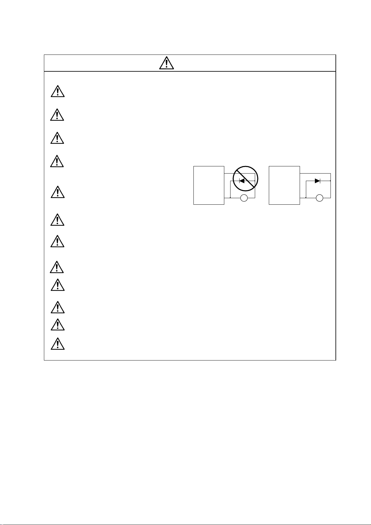
Do not directly connect a commercial
power supply to the servomotor. Failure
to observe this could result in a fault.
Servodrive unit
COM
(24VDC)
Servodrive unit
COM
(24VDC)
When using an inductive load such as a
relay, always connect a diode as a noise
measure parallel to the load.
Controloutput
signal
RA
Control output
signal
When using a capacitance load such as a lamp, always connect a protective resistor a s a
noise measure serial to the load.
Do not reverse the direction of a diode which connect to a DC relay for the control output
signals to suppress a surge. Connecting it backwards could cause the drive unit to malfunction
so that signals are not output, and emergency stop and other safety circuits are inoperable.
Do not connect/disconnect the cables connected between the units while the power is ON.
Securely tighten the cable connector fixing screw or fixing mechanism. An insecure fixing could
cause the cable to fall off while the power is ON.
When using a shielded cable instructed in the connection manual, always ground the cable with
a cable clamp, etc.
Always separate the signals wires from the drive wire and power line.
Use wires and cables that have a wire diameter, heat resistance and flexibility that conforms to
the system.
RA
Page 9
(3) Trial operation and adjustment
Check and adjust each program and parameter before starting operation. Failure to do so could
lead to unforeseen operation of the machine.
Do not make remarkable adjustments and changes as the operatio n could become unstable.
(4) Usage methods
Install an external emergency stop circuit so that the operation can be stopped and power
shut off immediately.
Turn the power OFF immediately if smoke, abnormal noise or odors are generated from the
servo drive unit or servomotor.
Unqualified persons must not disassemble or repair the unit.
Never make modifications.
Reduce magnetic damage by installing a noise filter. The electronic devices used near the
servo drive unit could be affected by magnetic noise.
Use the servo drive unit, servomotor and regenerative resistor with the designated combination.
Failure to do so could lead to fires or trouble.
The brake (magnetic brake) assembled into the servomotor is for holding, and must not be used
for normal braking.
There may be cases when holding is not possible due to the magnetic brake's life or the
machine construction (when ball screw and servomotor are coupled via a timing belt, etc.).
Install a stop device to ensure safety on the machine side.
After changing the programs/parameters or after maintenance and inspection, always test the
operation before starting actual operation.
Do not enter the movable range of the machine during automatic operation. Never place body
parts near or touch the spindle during rotation.
Follow the power supply specification conditions given in the separate specifications manual for
the power (input voltage, input frequency, tolerable sudden power failure time, etc.).
Set all bits to "0" if they are indicated as not used or empty in the explanation on the bits.
Do not use the dynamic brakes except during the emergency stop. Continued use of the
dynamic brakes could result in brake damage.
If a breaker is shared by several power supply units, the breaker may not activate when a
short-circuit fault occurs in a small capacity unit. This is dangerous, so never share the
breakers.
CAUTION
Page 10
(5) Troubleshooting
If a hazardous situation is predicted during power failure or product trouble, use a servomotor
with magnetic brakes or install an external brake mechanism.
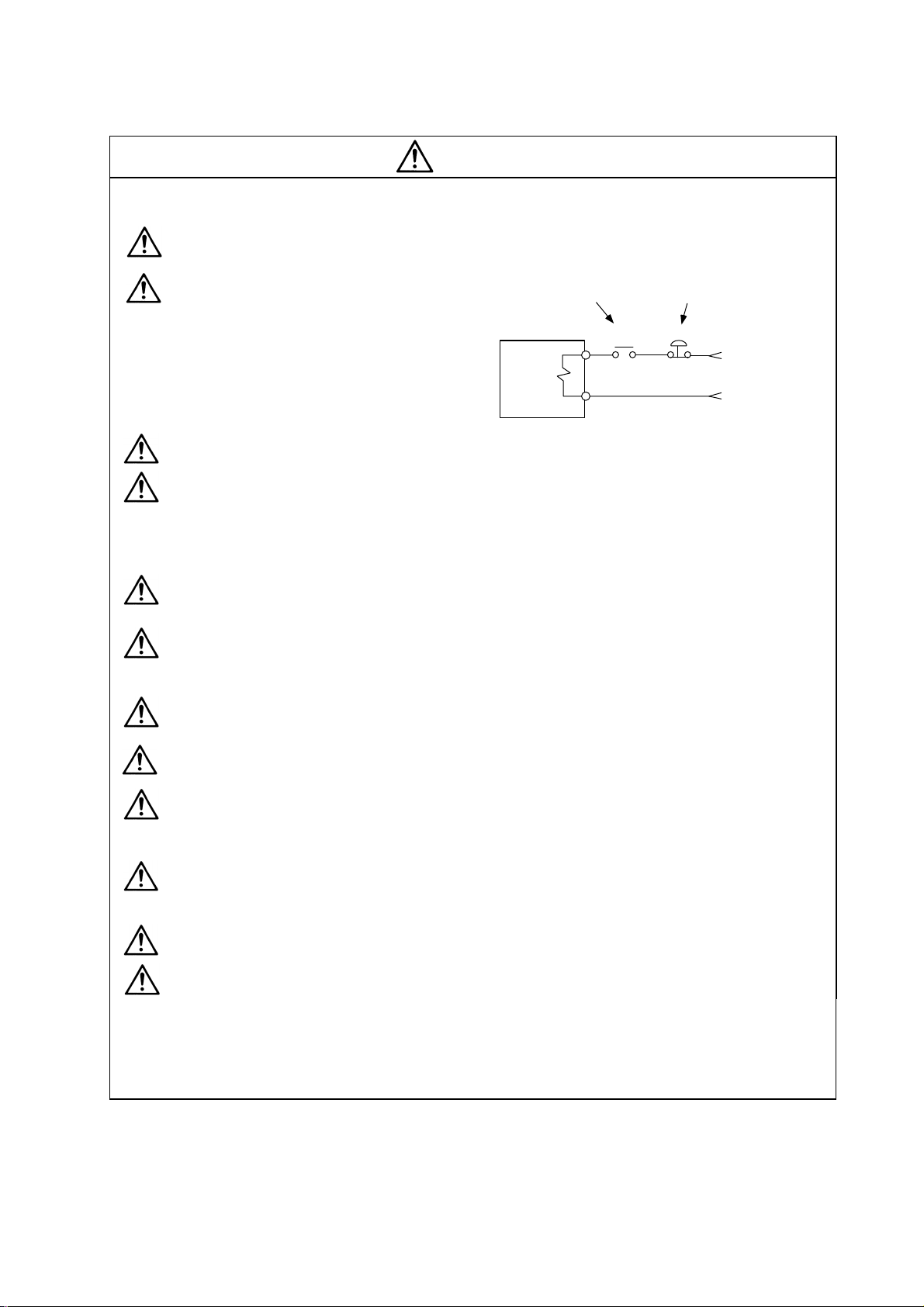
Use a double circuit configuration
that allows the operation circuit for
the magnetic brakes to be operated
even by the external emergency
stop signal.
CAUTION
Shut off with the servomotor
brake control output.
Servomotor
Magnetic
brake
Shut off with NC brake
control PLC output.
MBR
EMG
24VDC
Always turn the input power OFF when an alarm occurs.
Never go near the machine after restoring the power after a power failure, as the machine
could start suddenly. (Design the machine so that personal safety can be ensured even if the
machine starts suddenly.)
(6) Maintenance, inspection and part replacement
Always carry out maintenance and inspection after backing up the servo drive unit's programs
or parameters.
The capacity of the electrolytic capacitor will drop over time. To prevent secondary disasters
due to failures, replacing this part every five years when used under a normal environment is
recommended. Contact the Service Center or Service Station for replacement.
Do not perform a megger test (insulation resistance measurement) during inspections.
If the battery low warning is issued, save the machining programs, tool data and parameters
with an input/output unit, and then replace the battery.
Do not short circuit, charge, overheat, incinerate or disassemble the battery.
(7) Disposal
Treat this unit as general industrial waste. Note that MDS Series unit with a heat dissipating
fin protruding from the back of the unit contains substitute Freon. Do not dispose of this type
of unit as general industrial waste. Always return to the Service Center or Service Station.
Do not disassemble the servo drive unit or servomotor parts.
Dispose of the battery according to local laws.
(8) General precautions
The drawings given in this Specifications and Maintenance Instruction Manual show the covers and
safety partitions, etc., removed to provide a clearer explanation. Always return the covers or partitions to
their respective places before starting operation, and always follow the instructions given in this manual.
Page 11

CONTENTS
1. Installation
1-1 Installation of spindle motor.................................................................................................1-2
1-1-1 Environmental conditions .............................................................................................. 1-2
1-1-2 Shaft characteristics ...................................................................................................... 1-2
1-2 Installation of the control unit............................................................................................... 1-3
1-2-1 Environmental conditions .............................................................................................. 1-3
1-2-2 Installation direction and clearance ............................................................................... 1-4
1-2-3 Prevention of entering of foreign matter........................................................................ 1-4
1-2-4 Panel installation hole work drawings (Panel cut drawings)......................................... 1-5
1-2-5 Heating value................................................................................................................. 1-6
1-2-6 Heat radiation countermeasures................................................................................... 1-7
1-3 Installing the spindle detector.............................................................................................. 1-9
1-3-1 Magnetic sensor ............................................................................................................ 1-9
1-3-2 Spindle side detector................................................................................................... 1-11
1-4 Noise measures ................................................................................................................. 1-12
2. Wiring and Connection
2-1 Connection diagram............................................................................................................. 2-3
2-1-1 Part system connection diagram...................................................................................... 2-3
2-1-2 Detailed connection diagram ........................................................................................... 2-4
2-2 Main circuit terminal block/control circuit connector............................................................ 2-7
2-2-1 Names and applications of main circuit terminal block signals and control circuit
connectors..................................................................................................................... 2-7
2-2-2 Connector pin assignment............................................................................................. 2-8
2-3 Drive unit connection ......................................................................................................... 2-11
2-4 Motor and detector connection .......................................................................................... 2-14
2-4-1 Connection of the spindle motor.................................................................................. 2-14
2-5 Connection of power supply.............................................................................................. 2-17
2-5-1 Power supply input connection ...................................................................................... 2-17
2-5-2 Connecting the grounding cable.................................................................................. 2-20
2-5-3 Main circuit control ......................................................................................................... 2-21
2-6 Peripheral control wiring .................................................................................................... 2-23
2-6-1 Input interface ..............................................................................................................2-23
2-6-2 Output interface ........................................................................................................... 2-25
2-6-3 Spindle coil changeover .............................................................................................. 2-27
2-6-4 Wiring of an external emergency stop......................................................................... 2-30
3. Setup
3-1 Initial setup ........................................................................................................................... 3-2
3-1-1 Setting the rotary switch ................................................................................................3-2
3-1-2 Transition of LED display after power is turned ON...................................................... 3-3
3-2 Setting the initial parameters for the spindle drive unit....................................................... 3-4
3-2-1 Parameter setting method ............................................................................................. 3-4
3-2-2 List of spindle parameters ............................................................................................. 3-6
3-3 Initial adjustment of the spindle PLG................................................................................. 3-26
3-3-1 Adjusting the PLG installation...................................................................................... 3-26
Page 12

4. Spindle Adjustment
4-1 D/A output specifications for spindle drive unit ................................................................... 4-2
4-1-1 D/A output specifications............................................................................................... 4-2
4-1-2 Setting the output data ..................................................................................................4-2
4-1-3 Setting the output magnification.................................................................................... 4-3
4-2 Spindle control signal........................................................................................................... 4-5
4-2-1 Spindle control input (NC to SP) ................................................................................... 4-5
4-2-2 Spindle control output (SP to NC)............................................................................... 4-15
4-3 Adjustment procedures for each control ........................................................................... 4-27
4-3-1 Basic adjustments........................................................................................................ 4-27
4-3-2 Adjusting the acceleration/deceleration operation...................................................... 4-30
4-3-3 Adjusting the orientation control.................................................................................. 4-39
4-3-4 Adjusting the multi-point indexing orientation control.................................................. 4-55
4-3-5 Adjusting S-analog high-speed tapping control .......................................................... 4-64
4-3-6 Adjusting coil changeover............................................................................................ 4-69
5. Troubleshooting
5-1 Points of caution and confirmation ...................................................................................... 5-2
5-1-1 LED display when alarm or warning occurs.................................................................. 5-3
5-2 Protective functions list of units ...........................................................................................5-4
5-2-1 List of alarms.................................................................................................................. 5-4
5-2-2 List of warnings .............................................................................................................. 5-6
5-3 Troubleshooting ................................................................................................................... 5-7
5-3-1 Troubleshooting at power ON ....................................................................................... 5-7
5-3-2 Troubleshooting for each alarm No............................................................................... 5-8
5-3-3 Troubleshooting for each warning No......................................................................... 5-21
5-3-4 Troubleshooting the spindle system when there is no alarm or warning ................... 5-22
6. Maintenance
6-1 Inspections........................................................................................................................... 6-2
6-2 Service parts ........................................................................................................................ 6-2
6-3 Adding and replacing units and parts.................................................................................. 6-3
6-3-1 Replacing the drive unit.................................................................................................6-3
6-3-2 Replacing the unit fan.................................................................................................... 6-4
Appendix 1. Cable and Connector Specifications
Appendix 1-1 Selection of cable ..............................................................................................A1-2
Appendix 1-1-1 Cable wire and assembly............................................................................A1-2
Appendix 1-2 Cable connection diagram.................................................................................A1-4
Appendix 1-3 Connector outline dimension drawings.............................................................A1-8
Appendix 2. Compliance to EC Directives
Appendix 2-1 Compliance to EC Directives ............................................................................A2-2
Appendix 2-1-1 European EC Directives..............................................................................A2-2
Appendix 2-1-2 Cautions for EC Directive compliance ........................................................A2-2
Page 13

Appendix 3. EMC Installation Guidelines
Appendix 3-1 Introduction ........................................................................................................A3-2
Appendix 3-2 EMC instructions ...............................................................................................A3-2
Appendix 3-3 EMC measures..................................................................................................A3-3
Appendix 3-4 Measures for panel structure.............................................................................A3-3
Appendix 3-4-1 Measures for control panel unit...................................................................A3-4
Appendix 3-4-2 Measures for door .......................................................................................A3-4
Appendix 3-4-3 Measures for operation board panel...........................................................A3-5
Appendix 3-4-4 Shielding of the power supply input section................................................A3-5
Appendix 3-5 Measures for various cables .............................................................................A3-6
Appendix 3-5-1 Measures for wiring in panel .......................................................................A3-6
Appendix 3-5-2 Measures for shield treatment.....................................................................A3-6
Appendix 3-5-3 Spindle motor power cable..........................................................................A3-7
Appendix 3-5-4 Servo motor feedback cable .......................................................................A3-7
Appendix 3-5-5 Spindle motor power cable..........................................................................A3-8
Appendix 3-5-6 Spindle motor feedback cable.....................................................................A3-8
Appendix 3-6 EMC countermeasure parts ..............................................................................A3-9
Appendix 3-6-1 Shield clamp fitting ......................................................................................A3-9
Appendix 3-6-2 Ferrite core ................................................................................................A3-10
Appendix 3-6-3 Power line filter..........................................................................................A3-11
Appendix 3-6-4 Surge protector..........................................................................................A3-16
Appendix 4. Servo/spindle drive unit categories based on higher harmonic suppression
countermeasure guidelines
Appendix 4-1 Servo/spindle drive unit circuit categories based on higher harmonic suppression
countermeasure guidelines...............................................................................A4-2
Page 14

Contents for MDS-C1-SPA Series SPECIFICATIONS MANUAL (IB-1500150)
1. Introduction
1-1 Spindle drive system configuration .....................1-2
1-1-1 System configuration.................................................1-2
1-1-2 Unit outline type.........................................................1-3
1-2 Explanation of type..............................................1-4
1-2-1 Spindle motor type.....................................................1-4
1-2-2 Spindle drive unit type ...............................................1-5
1-2-3 Power supply unit type...............................................1-6
1-2-4 AC reactor type..........................................................1-7
2. Specifications
2-1 Spindle motor ......................................................2-2
2-1-1 Specifications............................................................2-2
2-1-2 Output characteristics................................................2-7
2-2 Drive unit .............................................................2-12
2-2-1 Installation environment conditions............................2-12
2-2-2 Spindle drive unit.......................................................2-12
2-2-3 Power supply unit ......................................................2-17
2-2-4 AC reactor .................................................................2-18
2-2-5 D/A output specifications for spindle drive unit...........2-19
2-2-6 Explanation of each part............................................2-20
2-3 Restrictions and precautions ...............................2-22
2-3-1 Layout of unit.............................................................2-22
2-3-2 Precautions for installing multiple power supply units2-23
2-3-3 Precautions when installing multiple spindle drive
units to one power supply unit...................................2-24
3. Characteristics
3-1 Spindle motor ......................................................3-2
3-1-1 Environmental conditions...........................................3-2
3-1-2 Shaft characteristics ..................................................3-2
3-2 Drive unit characteristics .....................................3-3
3-2-1 Environmental conditions...........................................3-3
3-2-2 Heating value.............................................................3-4
4. Dedicated Options
4-1 Orientation option................................................4-2
4-1-1 Magnetic sensor........................................................4-3
4-1-2 Spindle side detector (OSE-1024-3-15-68,
OSE-1024-3-15-68-8)................................................4-6
4-2 Cables and connectors .......................................4-8
4-2-1 Cable connection diagram.........................................4-8
4-2-2 List of cables and connectors ....................................4-9
5. Peripheral Devices
5-1 Selection of wire ..................................................5-2
5-1-1 Example of wires by unit............................................5-2
5-2 Selection the AC reactor, contactor and no-fuse
breaker ...............................................................5-4
5-2-1 Standard selection.....................................................5-4
5-2-2 Selection of contactor for changing over spindle
motor drive wire.........................................................5-5
5-3 Earth leakage breaker .........................................5-6
5-4 Branch-circuit protection .....................................5-7
5-4-1 Circuit protector .........................................................5-7
5-4-2 Fuse protection..........................................................5-7
5-5 Noise filter ...........................................................5-8
5-6 Surge absorber ...................................................5-9
5-7 Speedometer and load meter..............................5-10
5-8 Cable for peripheral control.................................5-11
5-8-1 Cable for external emergency stop............................5-11
(Note) This is the content for SPECIFICATION MANUAL version A. The structure of section and page number may be different
other than version B.
Appendix 1. Outline Dimension Drawings
Appendix 1-1 Outline dimension drawings of spindle
motor ..................................................A1-2
Appendix 1-1-1 SJ Series...................................................A1-2
Appendix 1-1-2 SJ-V Series................................................ A1-5
Appendix 1-1-3 SJ-VS Series .............................................A1-15
Appendix 1-2 Unit outline dimension drawings.........A1-17
Appendix 1-2-1 Spindle drive unit.......................................A1-17
Appendix 1-2-2 Power supply unit ......................................A1-21
Appendix 1-2-3 AC rector ...................................................A1-25
Appendix 2. Cable and Connector Specifications
Appendix 2-1 Selection of cable ...............................A2-2
Appendix 2-1-1 Cable wire and assembly...........................A2-2
Appendix 2-2 Cable connection diagram.................. A2-4
Appendix 2-3 Connector outline dimension drawings
............................................................A2-8
Appendix 3. Selection
Appendix 3-1 Selecting the power supply................. A3-2
Appendix 3-1-1 Selecting according to the continuous
rated capacity............................................A3-2
Appendix 3-1-2 Selection example .....................................A3-3
Appendix 4. Explanation of Large Capacity Spindle Unit
Specifications
Appendix 4-1 Explanation of large capacity spindle unit
specifications......................................A4-2
Appendix 4-1-1 Outline.......................................................A4-2
Appendix 4-1-2 List of units ................................................A4-2
Appendix 4-1-3 Selection of AC reactor (B-AL), contactor
and NFB....................................................A4-2
Appendix 4-1-4 Outline dimension drawings.......................A4-3
Appendix 4-1-5 Panel cut dimension drawing.....................A4-8
Appendix 4-1-6 Heating value.............................................A4-9
Appendix 4-1-7 Selecting the power capacity.....................A4-9
Appendix 4-1-8 Selecting the wire size...............................A4-9
Appendix 4-1-9 Drive unit connection screw size................A4-10
Appendix 4-1-10 Connecting each unit...............................A4-10
Appendix 4-1-11 Restrictions..............................................A4-12
Appendix 4-1-12 Parameters..............................................A4-14
Appendix 4-1-13 Precautions..............................................A4-14
Appendix 5. Explanation of Small Capacity Spindle Drive Unit
Specifications
Appendix 5-1 Explanation of small capacity spindle
drive unit specifications....................... A5-2
Appendix 5-1-1 Outline.......................................................A5-2
Appendix 5-1-2 List of units ................................................A5-2
Appendix 5-1-3 Outline dimension drawings.......................A5-2
Appendix 5-1-4 Drive unit specifications list ........................A5-4
Appendix 5-1-5 Heating value.............................................A5-5
Appendix 5-1-6 Selecting the wire size...............................A5-5
Appendix 5-1-7 Drive unit connection screw size................A5-5
Appendix 5-1-8 Restrictions................................................A5-6
Appendix 6. Compliance to EU EC Directives
Appendix 6-1 Compliance to EC Directives..............A6-2
Appendix 6-1-1 European EC Directives ............................A6-2
Appendix 6-1-2 Cautions for EC Directive compliance........A6-2
Page 15

Contents for MDS-C1-SPA Series SPECIFICATIONS MANUAL (IB-1500150)
Appendix 7. EMC Installation Guidelines
Appendix 7-1 Introduction .........................................A7-2
Appendix 7-2 EMC instructions .................................A7-2
Appendix 7-3 EMC measures ...................................A7-3
Appendix 7-4 Measures for panel structure ..............A7-3
Appendix 7-4-1 Measures for control panel unit..................A7-3
Appendix 7-4-2 Measures for door......................................A7-4
Appendix 7-4-3 Measures for operation board panel..........A7-4
Appendix 7-4-4 Shielding of the power supply input section
..................................................................A7-4
Appendix 7-5 Measures for various cables...............A7-5
Appendix 7-5-1 Measures for wiring in panel......................A7-5
Appendix 7-5-2 Measures for shield treatment....................A7-5
Appendix 7-5-3 Servomotor power cable............................A7-6
Appendix 7-5-4 Servomotor feedback cable .......................A7-6
Appendix 7-5-5 Spindle motor power cable.........................A7-7
Appendix 7-5-6 Spindle motor feedback cable....................A7-7
Appendix 7-6 EMC countermeasure parts................A7-8
Appendix 7-6-1 Shield clamp fitting.....................................A7-8
Appendix 7-6-2 Ferrite core ................................................A7-9
Appendix 7-6-3 Power line filter..........................................A7-10
Appendix 7-6-4 Surge protector..........................................A7-15
Appendix 8. Instruction Manual for Compliance with UL/c-UL
Standard
Appendix 8 Instruction Manual for Compliance with UL/c-UL
Standard.................................................A8-2
Appendix 9. Compliance with China Compulsory Product
Certification (CCC Certification) System
Appendix 9-1 Outline of China Compulsory Product
Certification System............................A9-2
Appendix 9-2 First Catalogue of Products subject to
Compulsory Product Certification........A9-2
Appendix 9-3 Precautions for Shipping Products......A9-3
Appendix 9-4 Application for Exemption ...................A9-4
Appendix 9-5 Mitsubishi NC Product Subject to/Not Subject
to CCC Certification ............................A9-5
(Note) This is the content for SPECIFICATION MANUAL version A. The structure of section and page number may be different
other than version B.
Page 16

1. Installation
1-1 Installation of spindle motor ............................................................................................................... 1-2
1-1-1 Environmental conditions............................................................................................................1-2
1-1-2 Shaft characteristics.................................................................................................................... 1-2
1-2 Installation of the control unit ............................................................................................................. 1-3
1-2-1 Environmental conditions............................................................................................................1-3
1-2-2 Installation direction and clearance.............................................................................................1-4
1-2-3 Prevention of entering of foreign matter......................................................................................1-4
1-2-4 Panel installation hole work drawings (Panel cut drawings).......................................................1-5
1-2-5 Heating value ..............................................................................................................................1-6
1-2-6 Heat radiation countermeasures................................................................................................. 1-7
1-3 Installing the spindle detector.............................................................................................................1-9
1-3-1 Magnetic sensor.......................................................................................................................... 1-9
1-3-2 Spindle side detector.................................................................................................................1-11
1-4 Noise measures ...............................................................................................................................1-12
1 - 1
Page 17
1. Installation
1-1 Installation of spindle motor
1. Do not hold the cables, axis or detector when transporting the motor. Failure to
observe this could lead to faults or injuries.
2. Securely fix the motor to the machine. Insufficient fixing could lead to the
motor deviating during operation. Failure to observe this could lead to
injuries.
CAUTION
1-1-1 Environmental conditions
Environment Conditions
Ambient temperature 0°C to +40°C (with no freezing)
Ambient humidity 90%RH or less (with no dew condensation)
Storage temperature -20°C to +65°C (with no freezing)
Storage humidity 90%RH or less (with no dew condensation)
Atmosphere
Altitude
(Note) Refer to each spindle motor specifications for details on the spindle motor vibration conditions.
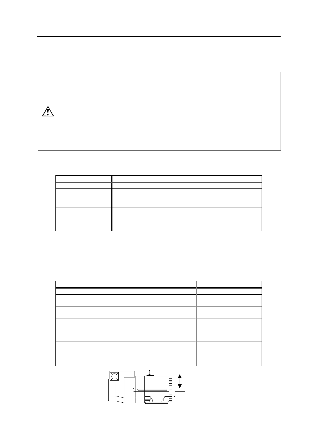
1-1-2 Shaft characteristics
There is a limit to the load that can be applied on the motor shaft. Make sure that the load applied on the
radial direction, when mounted on the machine, is below the tolerable values given below. These loads
also affect the motor output torque, so consider them when designing the machine.
SJ-V3.7-02ZM 490 N
SJ-V2.2-01, SJ-V3.7-01
SJ-V7.5-03ZM, SJ-V11-06ZM
SJ-V5.5-01, SJ-V11-08ZM
SJ-PMF01830-00
SJ-V7.5-01, SJ-V11-01
SJ-V22-06ZM, SJ-V30-02ZM, SJ-PMF03530-00
SJ-V11-09, SJ-V15-01, SJ-V15-03, SJ-V18.5-01, SJ-V18.5-03
SJ-V22-01, SJ-V22-05, SJ-V26-01, SJ-30A
SJ-22XW5 3920 N
SJ-37BP 4900 N
SJ-22XW8, SJ-45BP
SJ-V55-01
3. When coupling to a servomotor shaft end, do not apply an impact by
hammering, etc. The detector could be damaged.
4. Never touch the rotary sections of the motor during operations. Install a
cover, etc., on the shaft.
5. Do not apply a load exceeding the tolerable load onto the servomotor shaft.
The shaft could break. Failure to observe this could lead to injuries.
6. Do not connect or disconnect any of the connectors while the power is ON.
Indoors (Where unit is not subject to direct sunlight)
No corrosive gases, flammable gases, oil mist or dust
Operation/storage: 1000m or less above sea level
Transportation: 10000m or less above sea level
Spindle motor Tolerable radial load
980 N
1470 N
1960 N
2940 N
5880 N
Radial load
(Note) The load point is at the one-half of the shaft length.
1 - 2
Page 18

1-2 Installation of the control unit
1. Install the unit on noncombustible material. Direct installation on
combustible material or near combustible materials may lead to fires.
2. Follow the instructions in this manual and install the unit while allowing for
the unit weight.
3. Do not get on top of the units or motor, or place heavy objects on the unit.
Failure to observe this could lead to injuries.
4. Always use the unit within the designated environment conditions.
5. Do not let conductive objects such as screws or metal chips, etc., or
combustible materials such as oil enter the units.
CAUTION
6. Do not block the units intake and outtake ports. Doing so could lead to
failure.
7. The units and servomotor are precision devices, so do not drop them or apply
strong impacts to them.
8. Do not install or run units or servomotor that is damaged or missing parts.
9. When storing for a long time, please contact your dealer.
10. Always observe the installation directions. Failure to observe this could lead to
faults.
11. Secure the specified distance between the units and panel, or between the
units and other devices. Failure to observe this could lead to faults.
1. Installation
1-2-1 Environmental conditions
Environment Conditions
Ambient temperature 0°C to +55°C (with no freezing)
Ambient humidity 90%RH or less (with no dew condensation)
Storage temperature -15°C to +70°C (with no freezing)
Storage humidity 90%RH or less (with no dew condensation)
Atmosphere
Altitude
Vibration
(Note) When installing the machine at 1,000m or more above sea level, the heat dissipation characteristics will drop as the
altitude increases. The upper limit of the ambient temperature drops 1°C with every 100m increase in altitude. (The
ambient temperature at an altitude of 2,000m is between 0 and 45°C.)
no corrosive gases, inflammable gases, oil mist, dust or conductive particles
Indoors (no direct sunlight);
Operation/storage: 1000m or less above sea level
Transportation: 10000m or less above sea level
Operation/storage: 4.9m/s
Transportation: 49m/s
2
(0.5G) or less
2
(5G) or less
1 - 3
Page 19
1. Installation
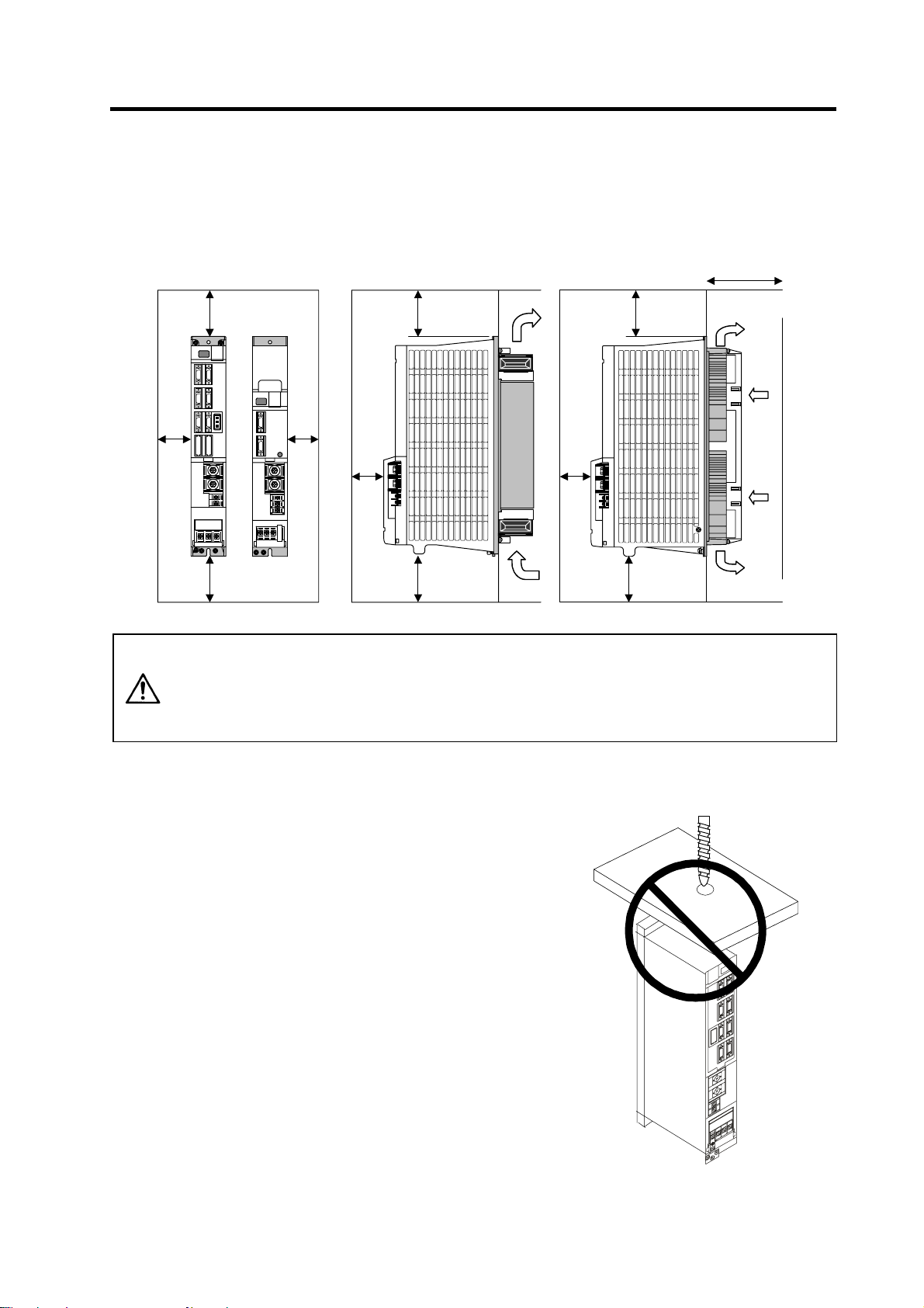
1-2-2 Installation direction and clearance
Wire each unit in consideration of the maintainability and the heat dissipation, as well as secure
sufficient space for ventilation.
75mm or more
10mm
or
more
100mm or
more
100mm or
more
10mm
or
more
50mm
or more
100mm or
more
100mm or
more
The ambient temperature condition for the power supply unit or the drive units is
55°C or less. Because heat can easily accumulate in the upper portion of the
CAUTION
units, give sufficient consideration to heat dissipation when designing the panel.
If required, install a fan in the panel to agitate the heat in the upper portion of the
units.
1-2-3 Prevention of entering of foreign matter
Treat the cabinet with the following items.
• Make sure that the cable inlet is dust and oil proof by using
packing, etc.
• Make sure that the external air does not enter inside by
using head radiating holes, etc.
• Close all clearances.
• Securely install door packing.
• If there is a rear cover, always apply packing.
• Oil will tend to accumulate on the top. Take special
measures such as oil-proofing to the top so that oil does
not enter the cabinet from the screw holds.
• After installing each unit, avoid machining in the periphery.
If cutting chips, etc., stick onto the electronic parts, trouble
may occur.
• When using the unit in an area with toxic gases or high
levels of dust, protect the unit with air purging (system to
blow clean air so that the panel's inner pressure is higher
than the outer pressure).
50mm
or more
100mm or
more
100mm or
more
1 - 4
Page 20
1. Installation
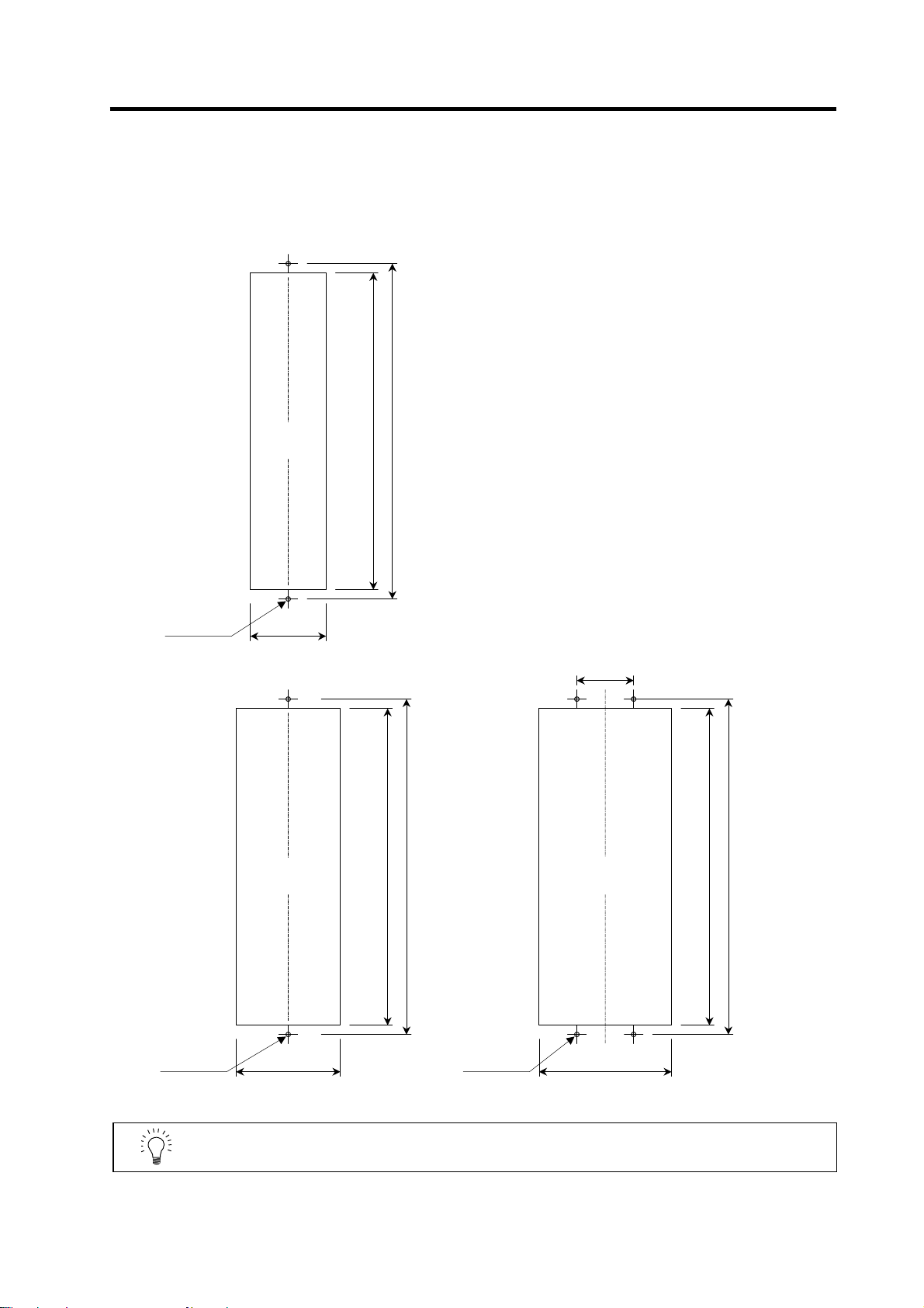
1-2-4 Panel installation hole work drawings (Panel cut drawings)
Prepare a square hole to match the unit width.
[Unit: mm]
2-M5 screw
Square hole
(Note 1)
82
Unit width: 90mm
Square hole
(Note 1)
342
360
342
360
60
Square hole
(Note 1)
342
360
2-M5 screw
112
Unit width: 120mm Unit width: 150mm
POINT
Attach packing around the square hole to provide a seal.
1 - 5
4-M5 screw
142
Page 21
1. Installation
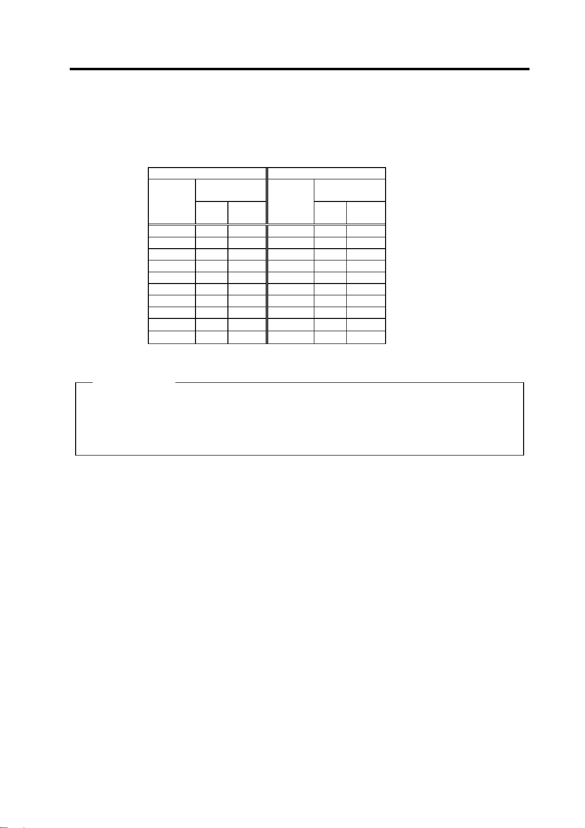
1-2-5 Heating value
Each heating value is calculated with the following values.
The values for the spindle drive unit are for a continuous rated output. The value for the power supply
unit includes the AC reactor's heating value.
Servo drive unit Power supply unit
Heating amount
Inside
panel
[W]
Outside
panel
Type
MDS-C1-
CV-300 46 274
CV-370 54 346
Type
MDS-C1-
SPA- 55 31 76 CV- 37 21 34
SPA- 75 35 102 CV- 55 23 42
SPA-110 41 140 CV- 75 25 55
SPA-150 48 187 CV-110 26 99
SPA-185 62 280 CV-150 29 126
SPA-220 65 301 CV-185 33 162
SPA-260 80 403 CV-220 35 175
SPA-300 98 522 CV-260 40 220
Heating amount
[W]
Inside
panel
Outside
panel
(Example 1)
When using MDS-C1-CV-185, MDS-C1-SPA[]-185[]
Total heating value = (33+162) + (62+280)
Heating value in panel = (33) + (62)
= 537 [W]
= 95 [W]
1 - 6
Page 22
1. Installation
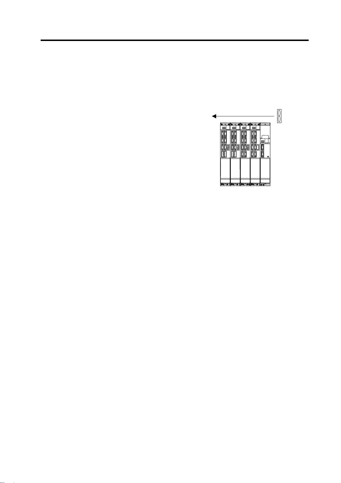
1-2-6 Heat radiation countermeasures
In order to secure reliability and life, design the temperature in the panel so that the ambient
temperature of each unit is 55°C or less.
If heat accumulates at the top of the unit, etc., install a fan so that the temperature in the panel remains
constant.
(Note) Due to the structure, heat easily accumulates at the
top of the unit. Install a fan in the power distribution
panel to circulate the heat at the top of the unit.
(Inside panel)
Wind sp eed 2m/s or more
Fan
1 - 7
Page 23
r
1. Installation
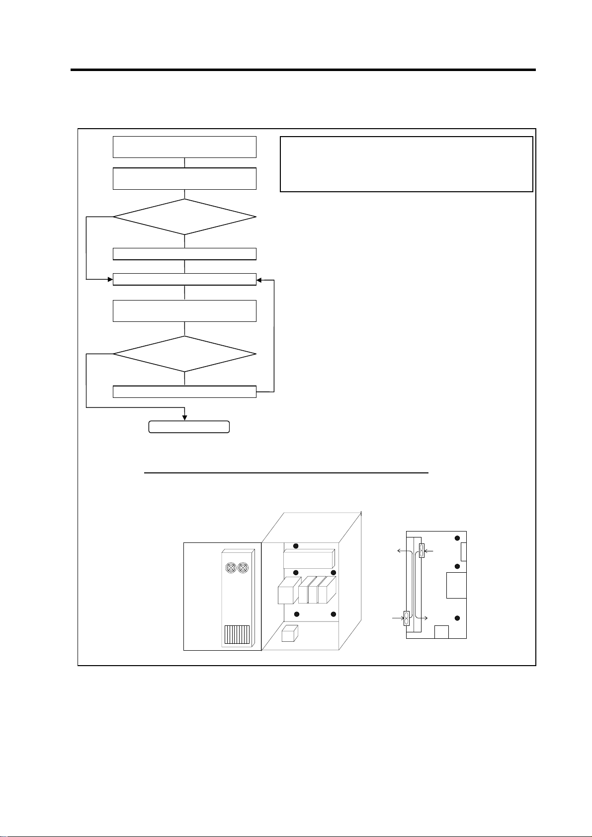
Please refer to following method for heat radiation countermeasures.
W ≤ W1
∆T
Calculate total heat radiation of each
mounted unit (W)
Calculate cabinet’s cooling capacity
Comparison of W and W1
Selection of heat exchanger
Collection of internal temperature rise
distribution data
≤10°C
(W1)
Mounting design
Evaluation
∆T>10°C
Improvements
Completion
W>W1
<Hypothetical conditions>
(1) Average temperature in cabinet : T ≤ 55°C
(2) Cabinet peripheral temperature : Ta ≤ 0°C to 45°C
(3) Internal temperature rise value : ∆T =T–Ta
<Supplement>
1) Refer to Specifications Manual, etc. for the heat
generated by each unit.
2) Enclosed cabinet (thin steel plate) cooling capacity
calculation equation
W1 = U × A × ∆T
U: 6W/m
4W/m
A: Effective heat radiation area (m
(Heat dissipation area in panel)
Sections contacting other objects are excluded.
∆T: Internal temperature rise value (10°C)
3) Points of caution for heat radiation countermeasures
when designing mounting state
• Layout of convection in panel
• Collect hot air at suction port in heat exchanger
cabinet.
4) Understanding the temperature rise distribution in the
panel
∆T (average value) ≤ 10°C
∆T
max (maximum value) ≤ 15°C
R (inconsistency) = (∆T
(Evaluate existence of heat spots)
2 ×
2
Examples of mounting and temperature measurement positions (reference)
z
Measurement position (example)
°C (with internal agitating fan)
× °C (without internal agitating fan)
max – ∆Tmin) ≤ 6°C
2
)
max= 10°C
Flow of air
Flow of air
Heat
exchange
Relay, etc
Unit
1 - 8
Page 24
w
1-3 Installing the spindle detector
1-3-1 Magnetic sensor
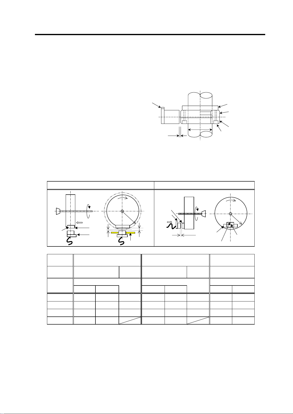
(1) Installing the magnetic sensor
• Tolerance to shaft dimension should
be "h6" on the part for installing a
magnet.
• 2-øG hole can be used for positioning
of spindle and magnet.
• Magnet shall be installed as shown to
the right.
• Misalignment between sensor head
and magnetic center line shall be
within ±2mm.
• There is an NS indication on the side of
the cover. Install so that the reference
notch on the sensor head comes to the
case side.
(2) Gap between magnet and sensor
1. Installation
Reference notch
Spindle
G hole
h6
Gap
Reference drawing for magnet installation
Case
Cover
Spindle damping scre
Spindle
Magnet
Circumference installation
Direction of
rotation
Face A
Reference
hole
Reference
notch
Min. gap
Face A
R
NS
Max. gap
Mounting plate
Reference
hole
Reference
notch
Face B
Horizontal installation
Spindle
Face B
Gap
Magnet
Reference
notch
Direction of
rotation
N
S
R
Reference
hole
Magnet
model
Installation
direction
R (Radius)
mm
40 11.5±0.5 2.7±0.5 6.0±0.5 10.0±0.5 1.22±0.5 5.0±0.5 6.25±0.5 3.30±0.5
50 9.5±0.5 2.8±0.5 6.0±0.5 8.0±0.5 1.31±0.5 5.0±0.5 6.00±0.5 3.70±0.5
60 8.5±0.5 3.0±0.5 6.0±0.5 7.0±0.5 1.50±0.5 5.0±0.5 5.75±0.5 3.85±0.5
70 8.0±0.5 3.4±0.5 7.0±0.5 2.38±0.5 5.50±0.5 3.87±0.5
Max. value Min. value Max. value Min. value Max. value Min. value
BKO-C1810H03 BKO-C1730H06 BKO-C1730H09
Circumference
installation
Gap mm Gap mm Gap mm
Horizontal
installation
Circumference
installation
Horizontal
installation
Circumference
installation
1 - 9
Page 25

(3) Magnet and sensor installation directions
• Install so that the magnet's reference hole and sensor's reference notch are aligned.
(Standard/high-speed standards)
• Install so that the magnet's N pole comes to the left side when the sensor's reference notch is
faced downward. (High-speed compact/high-speed ring)
Sensor
N S
|
Reference notch
Magnet
(4) Cautions
[1] Do not apply impacts on the magnet. Do not install strong magnets near the magnet.
[2] Sufficiently clean the surrounding area so that iron chips and cutting chips do not adhere to the
magnet. Demagnetize the round disk before installing.
[3] Securely install the magnet onto the spindle with an M4 screw. Take measures to prevent
screw loosening as required.
[4] Balance the entire spindle rotation with the magnet installed.
[5] Install a magnet that matches the spindle's rotation speed.
[6] When installing the magnet onto a rotating body's plane, set the speed to 6,000r/min or less.
[7] Install so that the center line at the end of the head matches the center of the magnet.
[8] The BKO-C1730 is not an oil-proof product. Make sure that oil does not come in contact with
BNO-C1730 or BKO-C1810.
[9] When connecting to the spindle drive unit, wire so that the effect of noise is suppressed.
1. Installation
Sensor
S N
|
Reference notch
Magnet
1 - 10
Page 26
1. Installation
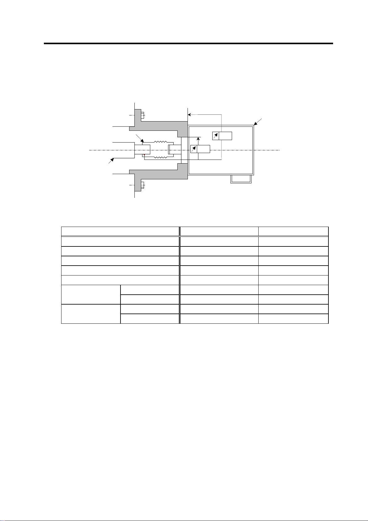
1-3-2 Spindle side detector
When coupling the spindle side detector with spindle, a flexible coupling should be used to couple the
spindle side detector with the spindle.
Detector
Flexible coupling
Opposite detector shaft
side
Detector and coupling installation accuracy
Recommended coupling
Recommendation 1 Recommendation 2
Manufacturer Tokushu Seiko Eagle
Model Model M1 FCS38A
Resonance frequency 1374Hz 3515Hz
Position detection error 0.8×10⁻³° 1.2×10⁻³°
Tolerable speed 20000r/min 10000r/min
Mis-alignment
Outline dimensions
Core deviation 0.7mm 0.16mm
Angle displacement
Max. length 74.5mm 33mm
Max. diameter
Refer to the coupling catalog, etc., for details on the coupling.
0.02
0.02
1.5° 1.5°
ø57mm ø38mm
1 - 11
Page 27
1. Installation
1-4 Noise measures
Noise includes "propagation noise" generated from the power supply or relay, etc., and propagated
along a cable causing the power supply unit or drive unit to malfunction, and "radiated noise"
propagated through air from a peripheral device, etc., and causing the power supply unit or drive unit to
malfunction.
Always implement these noise measures to prevent the peripheral devices and unit from malfunctioning.
The measures differ according to the noise propagation path, so refer to the following explanation and
take appropriate measures.
(1) General noise measures
• Avoid laying the drive unit's power line and signal wire in a parallel or bundled state. Always
separate these wires. Use a twisted pair shielded wire for the detector cable and signal wires
such as the communication cable connected with the NC, and accurately ground the devices.
• Use one-point grounding for the drive unit and motor.
• Accurately ground the AC reactor.
(2) Propagation noise measures
Take the following measures when noise generating devices are installed and the power supply
unit or drive unit could malfunction.
• Install a surge killer on devices (magnetic contacts, relays, etc.) which generate high levels of
noise.
• Install a power line filter in the stage before the power supply unit.
• Install a ferrite core on the signal wire.
• Ground the shield of the servo detector's cable with a cable clamp.
• Wire the spindle PLG detector cable away from other wires.
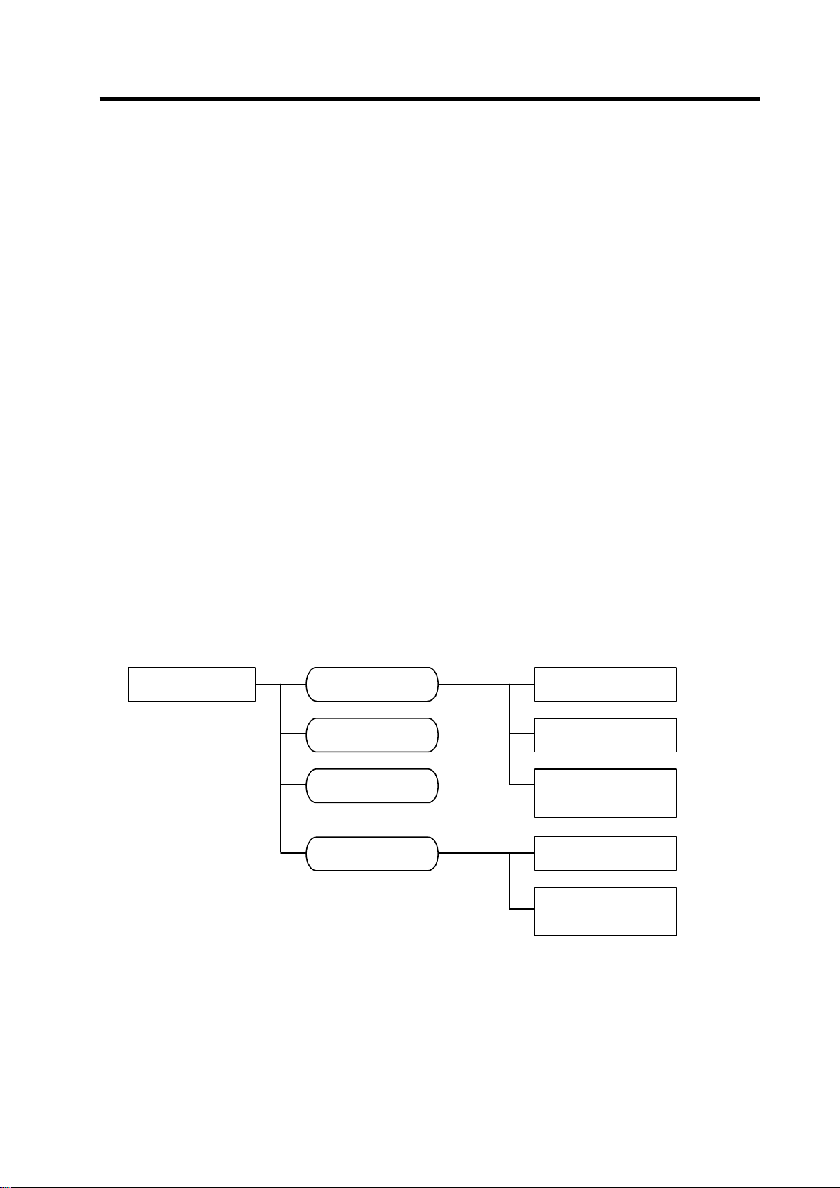
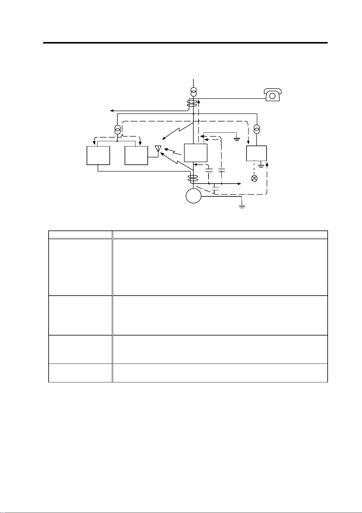
(3) Measures against radiated noise
The types of propagation paths of the noise and the noise measures for each propagation path are
shown below.
Noise generated from
drive unit
Airborne
propagation noise
Noise directly radiated
from drive unit
Path [1]
Magnetic ind uction
noise
Static ind uction
noise
Cable propagation
noise
Path [4]
and [5]
Noise radiated f rom
power line
Noise radiated f rom
spindle motor
Noise propagated over
power line
Noise lead in from
grounding wire by
leakage current
Path [2]
Path [3]Path [6]
Path [7]
Path [8]
1 - 12
Page 28
1. Installation
[5]
[7]
[2]
[1]
Drive
[3]
Spindle motor
Generated noise of drive system
unit
[4]
M
Instrument
[7]
Receiver
Noise propagation path Measures
When devices such as instrument, receiver or sensor, which handle minute signals and are easily
affected by noise, or the signal wire of these devices, are stored in the same panel as the drive
units and the wiring is close, the device could malfunction due to airborne propagation of the noise.
In this case, take the following measures.
[1] [2] [3]
[4] [5] [6]
[7]
[8]
(a) Install devices easily affected as far away from the drive units as possible.
(b) Lay devices easily affected as far away from the signal wire of the drive unit as possible.
(c) Avoid laying the signal wire and power line in a parallel or bundled state.
(d) Insert a line noise filter on the input/output wire or a radio filter on the input to suppress the
noise radiated from the wires.
(e) Use a shield wire for the signal wire and power line, or place in separate metal ducts.
If the signal wire is laid in parallel to the power line, or if it is bundled with the power line, the noise
could be propagated to the signal wire and cause malfunction because of the magnetic induction
noise or static induction noise. In this case, take the following measures.
(a) Install devices easily affected as far away from the drive unit as possible.
(b) Lay devices easily affected as far away from the signal wire of the drive unit as possible.
(c) Avoid laying the signal wire and power line in a parallel or bundled state.
(d) Use a shield wire for the signal wire and power line, or place in separate metal ducts.
If the power supply for the peripheral devices is connected to the power supply in the same system
as the drive units, the noise generated from the power supply unit could back flow over the power
line and cause the devices to malfunction. In this case, take the following measures.
(a) Install a radio filter on the power supply unit's power line.
(b) Install a power filter on the power supply unit's power line.
If a closed loop is created by the peripheral device and drive unit's grounding wire, a leakage
current could flow and cause the device to malfunction.
In this case, change the device grounding methods and the grounding place.
[6]
[2]
Sensor
power
supply
Sensor
[8]
1 - 13
Page 29

2. Wiring and Connection
2-1 Connection diagram........................................................................................................................... 2-3
2-1-1 Part system connection diagram..................................................................................................2-3
2-1-2 Detailed connection diagram........................................................................................................ 2-4
2-2 Main circuit terminal block/control circuit connector ..........................................................................2-7
2-2-1 Names and applications of main circuit terminal block signals and control circuit connectors ..2-7
2-2-2 Connector pin assignment ..........................................................................................................2-8
2-3 Drive unit connection........................................................................................................................ 2-11
2-4 Motor and detector connection ........................................................................................................2-14
2-4-1 Connection of the spindle motor ...............................................................................................2-14
2-5 Connection of power supply............................................................................................................. 2-17
2-5-1 Power supply input connection .................................................................................................2-17
2-5-2 Connecting the grounding cable ............................................................................................... 2-20
2-5-3 Main circuit control .................................................................................................................... 2-21
2-6 Peripheral control wiring...................................................................................................................2-23
2-6-1 Input interface............................................................................................................................ 2-23
2-6-2 Output interface.........................................................................................................................2-25
2-6-3 Spindle coil changeover............................................................................................................2-27
2-6-4 Wiring of an external emergency stop.......................................................................................2-30
2 - 1
Page 30
2. Wiring and Connection
1. Wiring work must be done by a qualified technician.
2. Wait at least 15 minutes after turning the power OFF and check the voltage
with a tester, etc., before starting wiring. Failure to observe this could lead to
electric shocks.
3. Securely ground the drive units and spindle motor.
DANGER
4. Wire the drive units and spindle motor after installation. Failure to observe this
could lead to electric shocks.
5. Do not damage, apply forcible stress, place heavy items on the cables or get
them caught. Failure to observe this could lead to electric shocks.
6. Always insulate the power terminal connection section. Failure to observe
this could lead to electric shocks.
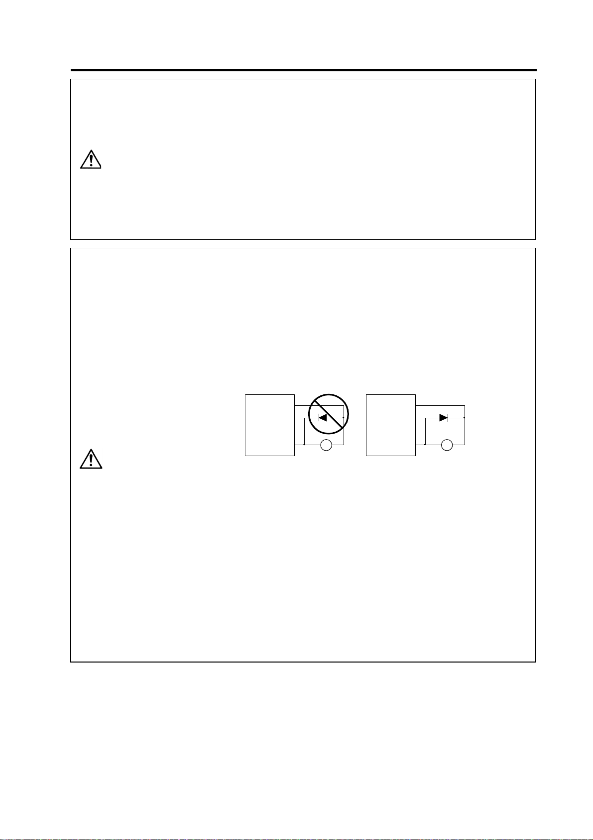
1. Correctly and securely perform the wiring. Failure to do so could result in
runaway of the spindle motor or injury.
2. Do not mistake the terminal connections.
Failure to observe this item could lead to ruptures or damage, etc.
3. Do not mistake the polarity ( + ,
- ). Failure to observe this item could lead to
ruptures or damage, etc.
4. Do not mistake the direction of the diodes for the surge absorption installed
on the DC relay for the general-purpose output and contactor (magnetic
contactor) control. The signal might not be output when a failure occurs.
Servodrive unit
COM
(24VDC)
Servodrive unit
COM
(24VDC)
CAUTION
Controloutput
signal
RA
Control output
signal
RA
5. Electronic devices used near the drive units may receive magnetic
obstruction. Reduce the effect of magnetic obstacles by installing a noise
filter, etc.
6. Do not install a phase advancing capacitor, surge absorber or radio noise
filter on the power line (U, V, W) of the spindle motor.
7. Do not modify this unit.
8. The half-pitch connector (CN10, etc.) on the front of the drive units have the
same shape. If the connectors are connected incorrectly, faults could occur.
Make sure that the connection is correct.
9. When grounding the motor, connect to the protective grounding terminal on
the drive units, and ground from the other protective grounding terminal.
(Use one-point grounding) Do not separately ground the connected motor
and drive unit as noise could be generated.
2 - 2
Page 31

r
r
r
2. Wiring and Connection
2-1 Connection diagram
2-1-1 Part system connection diagram
No-fuse
breaker
R
S
T
: Main circuit
: Control circuit
External emergency stop input
AC
Contacto
reactor
Ground
Breake
MC
CN23
L1
L2
L3
MC1
L11
L21
TE1
TE3
TE2
CN4
CN9
L+
L-
Ground
L+
L-
L11
L21
Spindle drive unitPower supply unit
CN4
General purpose, general-purpose output
CN10
TE2
TE3
TE1
Orientation position command,
General-purpose output
CN11
Digital speed command,
general-purpose • error output
CN12
Speed • load meter, serial I/F
CN9A
S-analog speed command, pulse feedback
CN8A
Spindle side detector
CN6
CN5
U
V
W
Spindle
motor
Ground
PLG
ENC
NC
PC
DIO
Meter
Personal compute
(Note 1) The connection method will differ according to the used motor.
(Note 2) The main circuit (
) and control circuit ({) are safely separated.
2 - 3
Page 32

2. Wiring and Connection
2-1-2 Detailed connection diagram
(1) With no orientation / When using motor built-in encoder orientation
B-AL
NFB3
Contactor
TYPE
MDS-C1-CV-□
TYPE
MDS-C1-SPA-
□
2 - 4
Page 33

2. Wiring and Connection
(2) When using magnetic sensor orientation
B-AL Contactor
NFB3
TYPE
MDS-C1-CV-□
TYPE
MDS-C1-SPA-□
2 - 5
Page 34

(3) When using encoder orientation
2. Wiring and Connection
B-AL Contactor
NFB3
TYPE
MDS-C1-CV-□
TYPE
MDS-C1-SPA-□
2 - 6
Page 35

2. Wiring and Connection
2-2 Main circuit terminal block/control circuit connector
2-2-1 Names and applications of main circuit terminal block signals and control circuit
connectors
The following table shows the details for each terminal block signal.
Name Signal name Description
L1 . L2 . L3
L11 L21
MC1
U . V . W
LU . LV . LW
MU . MV . MW
Main circuit power
supply
Control circuit power
supply
Contactor control
Motor output
(Single-axis unit)
Motor output
(Dual-axis unit)
Protective grounding
(PE)
Main circuit power supply input terminal
Connect a 3-phase 200VAC/200 to 230VAC, 50/60Hz power supply.
Control circuit power supply input terminal
Connect a single-phase 200VAC/200 to 230VAC, 50/60Hz power supply.
Contactor control terminal
The MC1 terminal has the same phase as L21. Connect to a different phase than the
phase connected to L21.
Servo/spindle motor power output terminal
The servo/spindle motor power terminal (U, V, W) is connected.
Servo motor power output terminal (L-axis/M-axis)
The servo/spindle motor power terminal (U, V, W) is connected.
Grounding terminal
The servomotor/spindle motor grounding terminal is connected and grounded.
1. Always use one AC reactor per power supply unit. Failure to observe this
could lead to unit damage.
CAUTION
2. When sharing a breaker for several power supply units, of a short-circuit
fault occurs in a small capacity unit, the breaker could trip. This can be
hazardous, so do not share the breaker.
3. Be sure to use the breaker of proper capacity for each power supply unit.
2 - 7
Page 36

2-2-2 Connector pin assignment
2. Wiring and Connection
CAUTION
Do not apply a voltage other than that specified in Instruction Manual on each
terminal. Failure to observe this item could lead to rupture or damage, etc.
(1) Main circuit terminal block
Power supply unit
Terminal
Terminal
position
Unit
MDS-C1-CV-37 to 75 MDS-C1-CV-110 to 370
[2]
[3]
[1]
[2]
[3]
[1]
[4]
U V W
[1] TE1
Compatible unit CV-37 to 75
Screw size
Tightening torque
[2] TE2
[3] TE3
Terminal specification/Pin assignment
Compatible unit CV-37 to 75
[4]
Screw size M4
Tightening torque 2.0Nm
L+
L-
L11
L21
MC1
U V W
Compatible unit CV-110 to 185 CV-220 to 370
M4
1.6Nm
Compatible unit CV-37 to 370
Screw size
Tightening torque
Compatible unit CV-37 to 75 CV-110 to 370
Screw size M4 M4
Tightening torque 2.0Nm 1.6m
Screw size
Tightening torque
M6
5.0Nm
M5 M8
3.37Nm 13.2Nm
Compatible unit CV-110 to 185 CV-220 to 370
Screw size M5 M8
Tightening torque 3.37Nm 13.2Nm
[4]
2 - 8
Page 37

[2]
[3]
Spindle drive unit
Terminal
Terminal
position
[1] TE1
[2] TE2
Terminal specification/Pin assignment
[3] TE3
[4]
2. Wiring and Connection
Unit
MDS-C1-SPA- 55 to 185 220 to 300
Screw size M5 M8
Tightening torque 3.2Nm 13.2Nm
L+
L-
L11
L21
MDS-C1-SPA-55 to 300
[1]
[4]
U V W
Compatible unit All capacity
Screw size M6
Tightening torque 5.0Nm
Compatible unit All capacity
Screw size M4
Tightening torque 2.0Nm
The PE screw size is the same as TE1.
2 - 9
Page 38

Pin N
No.1
No.1
1
(2) Control circuit connector
Unit
Terminal
[5] CN5 [6] CN6 [9] CN8A [3] CN9A
Pin assignment
[7] CN10 [1] CN11 [2] CN12
Pin assignment
Connector
position
[1] CN11
[2] CN12
[3] CN9A
[4] CN4
[5] CN5
[6] CN6
[7] CN10
[8] CN8A
1 GND 11 GND
2 RD 12 RD*
3 MOH 13 RG
4 SD 14 SD*
5 P15 15 N15
6 PA 16 RA
7 PB 17 RB
8 PZ 18 9 P24 19 -
10 - 20 -
Connector specifications
1 REDY 11 SRN
2 SRI 12 IN1
3 IN2 13 IN3
4 IN4 14 IN5
5 IN6 15 IN7
6 IN8 16 IN9
7 - 17 +24V
8 IN10 18 IN11
9 IN12 19 CES1
10 RG 20 OUT6C
2. Wiring and Connection
[1]
[3]
[5]
[7]
Pin assignment
1 GND 11 GND
2 MA 12 MA*
3 MB 13 MB*
4 MZ 14 MZ*
5 P15B 15 GND
6 MSA 16 MSC
7 LSA 17 LSC
8 - 18 9 - 19 P5
10 P5 20 P5
Pin assignment
1 1H 11 2H
2 3H 12 4H
3 5H 13 6H
4 7H 14 8H
5 9H 15 10H
6 11H 16 12H
7 OUT1 17 OUT2
8 OUT3 18 OUT4
9 OUT5 19 CES3
10 OUT6 20 OUT7
MDS-C1-SPA-55 to 300
o.
No.10
No.20
Pin assignment
1 GND 11 GND
2 SYA 12 SYA*
3 SYB 13 SYB*
4SYZ 14SYZ*
5 SES 15 ORS
6RP 16OR3
7 SE1 17 OR2
8 SE2 18 OR1
9- 19-
10 - 20 -
Pin assignment
1 R1 11 R2
2 R3 12 R4
3 R5 13 R6
4 R7 14 R8
5 R9 15 R10
6 R11 16 R12
7 OUT1C 17 OUT2C
8 OUT3C 18 OUT4C
9 OUT5C 19 CES2
10 FA 20 FC
[2]
[4]
[6]
[9]
Pin assignment
1 GND 11 GND
2 DR 12 DX
3 CLK 13 FSX
4 P5 14 5 RX 15 TX
6 - 16 7 IU 17 IV
8 OUT8 18 P5
9 SM0 19 LM0
10 - 20 -
2 - 10
Page 39

2. Wiring and Connection
2-3 Drive unit connection
In this section, the connection between the spindle drive unit and power supply unit is shown. There is
space between units in the following diagram to make clearly understandable. However, actually, install
the drive units so that the space between the drive units is within 3cm.
POINT
(1) When using one power supply unit for one spindle drive unit
Even if two or more spindle drive units are used, keep the setting of the spindle
drive unit’s rotary switch to “0”. This switch has no relation to the axis No.
MDS-C1-SPA MDS-C1-CV
CN4
CN4
Connection when using one power supply unit
2 - 11
Page 40

2. Wiring and Connection
(2) When using two power supply units and connecting one spindle drive unit with each power
supply unit
Two or more power supply units may be required if the spindle drive unit capacity is large in a
machine applying two spindles specification. Make sure that the powers (L+, L-) of both power
supply units are supplied to only one spindle drive unit connected with each power supply, and do
not connect each other's powers.
MDS-C1-SPA
(No.1)
CN4
MDS-C1-CV
(No.1)
CN4
Power
cannot be
supplied
MDS-C1-SPA
(No.2)
CN4
MDS-C1-CV
(No.2)
CN4
Connections when using two power supply units
2 - 12
Page 41
2. Wiring and Connection
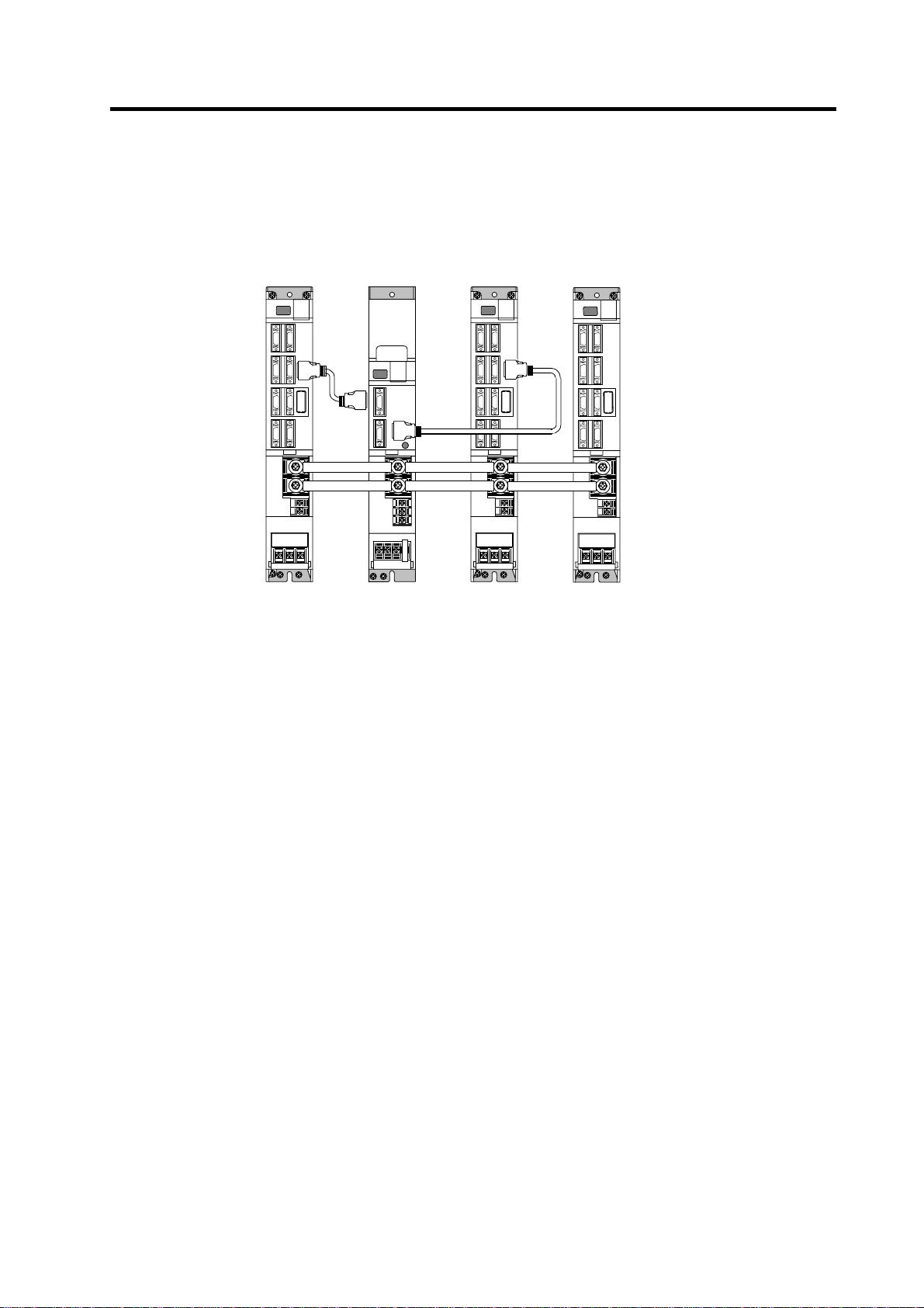
(3) When connecting two or more spindle drive units with one power supply unit
Connect units according to the following cautions.
MDS-C1-SPA
MDS-C1-CV
MDS-C1-SPA
MDS-C1-SPA
(No.1)
CN4
CN4
CN9
Connections when sharing one power supply
(
No.2
)
CN4
(
No.3
)
(Note 1) Connecting power supply unit and spindle drive unit.
Connect C1-CV CN4 and C1-SPA (No. 1) CN4 to C1-CV CN9 and C1-SPA (No.2) CN4. If
C1-SPA is connected with three or more axes, leave CN4 for C1-SPA (No. 3) and
following open.
Note that the C1-CV can be controlled (READY ON/OFF, alarm display, etc.) only by the
spindle drive unit connected to C1-CV CN4.
(Note 2) Make sure that the machine ready complete input turns ON and OFF simultaneously for all
the spindle drive units. Do not allow the signal to turn ON and OFF for only one spindle
drive unit.
(Note 3) When turning the machine ready complete input OFF during an emergency stop, always
have all the spindle drive units output the zero speed signal before turning the signal OFF.
(Note 4) If an alarm occurs in one of the spindle drive units, turn OFF the machine ready complete
input OFF for all the spindle drive units.
(Note 5) When connecting three or more spindle drive units, install the large-capacity spindle drive
units on both sides of the power supply unit.
2 - 13
Page 42

2. Wiring and Connection
2-4 Motor and detector connection
2-4-1 Connection of the spindle motor
Refer to each motor specifications for details on the motor side connection destination, specifications
and outline, and for the spindle PLG detector specifications.
(1) Connecting the motor built-in PLG
MDS-C1-SPA
Detector connector : CN5
Pin No.
BU BW BV
Max. 30m
U V W
Option cable : CNP5
Power cable
CN5
U VW
Pin
1
2
3
4
5
6
7
8
9
10
No.1
No.10
Name
LG
MOH
P15(+15V)
PA
PB
PZ
No.11
No.20
Pin
11
12
13
14
15
16
17
18
19
20
Name
RG
N15(-15V)
RA
RB
Spindle m otor
Cooling fan termin al
block (BU,BV,BW)
Ground ing terminal
Motor pow er terminal
block (U,V,W)
Either a single-phas e or 3-phase power s upply is us ed for the co oling f an.
(Note)
R efer to the Spindle Motor Specifications for det ails.
CAUTION
The shield of spindle detector cable is not FG. Do not ground.
2 - 14
Example for 3-phase cooling fan
power supply
Page 43

(2) Connecting the magnetic sensor
Refer to section (1) for connection with the spindle motor.
2. Wiring and Connection
MDS-C1-SPA
Detector connector : CN6
Pin No.
Max. 30m
U V W
Option cable : CNP5
Power c able
No.1
CN5
U VW
CN6
Pin
1
2
3
4
5
6
7
8
9
10
No.10
Name
P15(+15V)
MAG
LS
Pin
11
12
13
14
15
16
17
18
19
20
No.11
No.20
Name
LG
MAGR
LSR
Spindle motor
Magnetic sensor
Spindle
Option cable : CNP6M
1. The shield of spindle detector cable is not FG. Do not ground.
CAUTION
2. The magnetic sensor orientation is not available with a machine having a
gear ratio between the motor and spindle exceeding 1:31.
2 - 15
Page 44

2. Wiring and Connection
(3) Connecting the spindle side detector
Refer to section (1) for connection with the spindle motor.
MDS-C1-SPA
Detector connector : CN6
Pin No.
Max. 30m
U V W
Option cable : CNP5
Power cable
CN5
U VW
CN6
Pin
1
2
3
4
5
6
7
8
9
10
No.1
No.10
Name
LG
MA
MB
MZ
P5(+5V)
Pin
11
12
13
14
15
16
17
18
19
20
No.11
No.20
Name
LG
MA*
MB*
MZ*
LG
P5(+5V)
P5(+5V)
Spindle motor
Spindle
Spindle side detector
Option cable: CNP6A
CAUTION
The shield of spindle detector cable is not FG. Do not ground.
2 - 16
Page 45
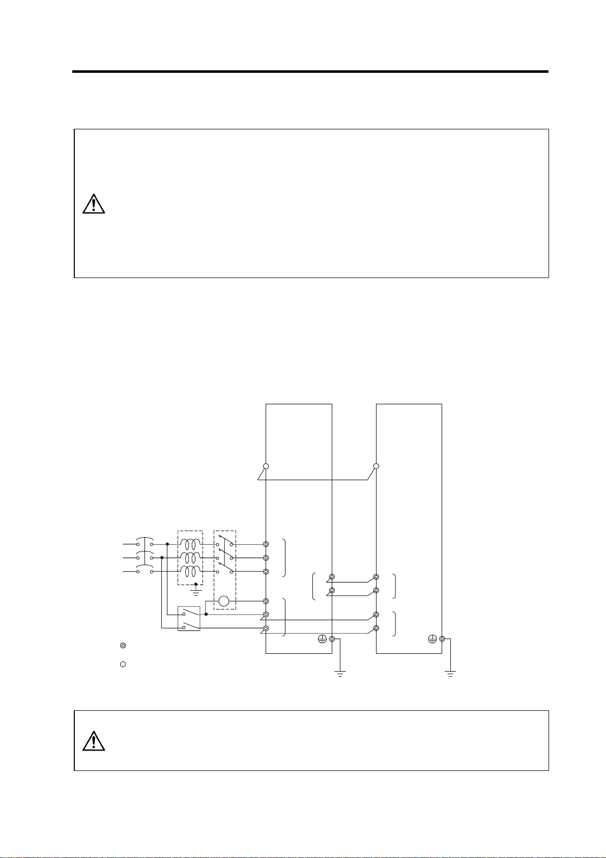
r
2. Wiring and Connection
2-5 Connection of power supply
1. Make sure that the power supply voltage is within the specified range of each
unit. Failure to observe this could lead to damage or faults.
2. For safety purposes, always install a No-fuse breaker (NFB), and make sure
that the circuit is cut off when an error occurs or during inspections.
3. The wire size will differ according to each drive unit capacity.
CAUTION
2-5-1 Power supply input connection
(1) When using one power supply unit
Install the drive units so that the distance between power supply unit and spindle drive unit will be
3cm or less.
4. For safety purposes, always install a magnetic contactor (contactor) on the
main circuit power supply input. Large rush currents will flow when the power
is turned ON.
5. A semiconductor element is used in the power supply unit's magnetic contact
drive circuit, and a surge absorber is installed to protect the element.
Therefore, a leakage current of approx. 15mA is passed. Confirm that the
exciting coil in the magnetic contact will not function at 15mA or less.
MDS-C1-CV
MDS-C1-SPA
L+
L-
L11
L21
CN4
TE2
TE3
Ground
No-fuse
breaker
R
S
T
: Main circuit
: Control circuit
Ground
AC
reactor
Breaker
Contacto
MC
CN4
L1
TE1
L2
L3
MC1
L11
L21
TE3
TE2
L+
L-
Ground
1. The power supply unit is a power supply regenerative type converter; an AC
reactor is surely installed in the power supply line.
CAUTION
2. When connecting to the TE3 terminal, connect to the power supply side
(primary side) of the AC reactor.
2 - 17
Page 46
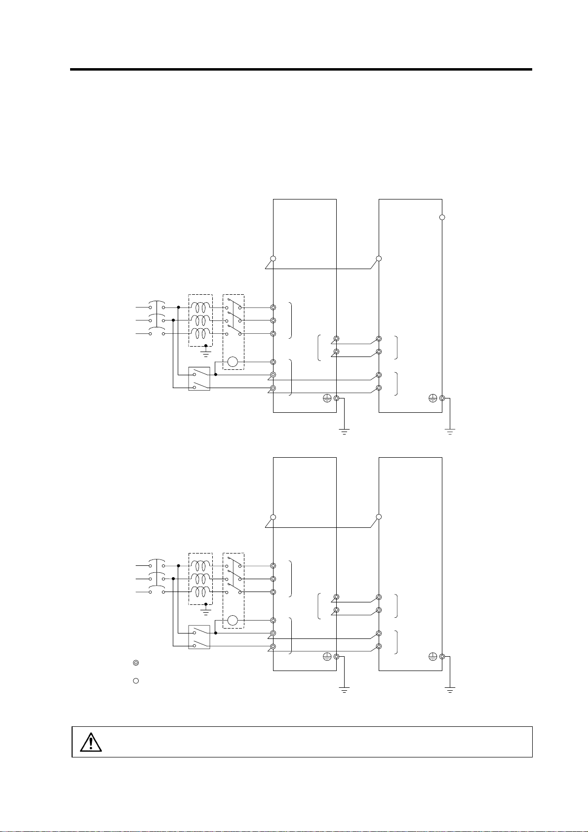
r
r
r
r
r
2. Wiring and Connection
(2) When using two power supply units, and connecting one spindle drive unit with each power
supply unit
Install a no-fuse breaker and a contactor for each of the power supply units.
Install the drive units so that the distance between power supply unit and spindle drive unit will be
3cm or less. The installation distance between No.1 and No.2.is not particularly specified.
MDS-C1-CV(No.1)
MDS-C1-SPA(No.1)
R
S
T
R
S
T
: Main circuit
No-fus e
breaker
No-fus e
breake
CN4
AC
Contacto
reactor
Breake
L1
TE1
L2
L3
MC
MC1
L11
L21
L+
TE2
L-
TE3
Ground Ground
Ground
MDS-C1-CV(No.2)
CN4
AC
Contacto
reactor
Ground
Breake
L1
TE1
L2
L3
MC
MC1
L11
L21
TE3
TE2
L+
L-
CN4
TE2
L+
L-
TE3
L11
L21
MDS-C1-SPA(No.2)
CN4
TE2
L+
L-
TE3
L11
L21
: Control circuit
Ground
Ground
CAUTION
An AC reactor and breaker are required for each power supply unit.
2 - 18
Page 47

r
r
2. Wiring and Connection
(3) When connecting one power supply unit with two spindle drive units
Only the spindle drive unit connected to the power supply unit's CN4 connector becomes the power
supply unit control axis.
MDS-C1-SPA(No.1) MDS-C1-CV MDS-C1-SPA(No.2)
R
S
T
No-fuse
breaker
CN4
CN9
AC
reactor
Ground
Breake
Contacto
MC
L1
TE1
L2
L3
MC1
L11
L21
TE3
TE2
L+
L-
Ground
CN4
L+
L-
L11
L21
TE2
TE3
Ground
CN4
L+
L-
L11
L21
TE2
TE3
Ground
MDS-C1-SPA(No.3)
TE2
L+
L-
TE3
L11
L21
Ground
1. When connecting two or more spindle drive units, install the large-capacity
drive units on both sides of the power supply unit.
CAUTION
2. Install units so that the “L+” and “L-” of each unit are in alignment and each
space between units is kept to 3cm or less.
2 - 19
Page 48

2. Wiring and Connection
2-5-2 Connecting the grounding cable
(1) Connecting the protective grounding (PE) and frame ground (FG)
Each unit has a terminal or mounting hole to connect PE (
Please connect an earth wire to the main ground of a cabinet or a machine frame at one point.
Ground each device according to the grounding conditions set forth by each country. (Typically, a
Y-connection neutral point ground is used in Europe.)
PE: Grounding to provide protection from electric shock, etc.
FG: Grounding to stabilize the operation of the devices, etc. (Suppress noise)
) or FG.
Do not connect the grounding cable from
POINT
each unit directly to the grounding plate.
Noise from other units could result in
malfunctions.
(2) Grounding cable size
Earth wire size should follow the following table.
Type Grounding cable size (Required grounding)
MDS-C1-SPA(No.1)
SJ Series motor
MDS-C1-CV
MDS-C1-SPA(No.2)
Grounding pl ate
Unit
Unit
B-AL
Grounding
Grounding
plate
plate
MDS-C1-CV Unit Larger than thickness of wire connected to TE1 (L1/L2/L3). (PE)
MDS-C1-SPA[] Unit Larger than thickness of wire connected to TE1 (U/V/W). (PE)
B-AL (AC Reactor) 5.5 mm
2
(AWG10) or more (FG)
2 - 20
Page 49

2-5-3 Main circuit control
(1) Contactor ON sequence
Main circuit power is turned ON in the sequence shown below when an emergency stop status is
canceled.
Machine ready complete input
signal (READY)
Contactor control output (MC1)
2. Wiring and Connection
OFF
ON
ON
OFF
Emergency stop (EMG)
PN bus voltage
Motor ON (GATE)
In ready ON signal (ron)
Forward run/reverse run signal
(SRN, SRI)
OFF
ON
ON
OFF
ON
OFF
ON
OFF
0
Contactor ON sequence
500 1000 1500
PN charging completed
Ready completion
・
Command input enable
Time (ms)
2 - 21
Page 50

(2) Contactor shutoff sequence
During the emergency stop signal input (EMG), if the setting of SP193 is "0" or "1" after the spindle
motor decelerates to stop, the contactor is turned OFF after a certain amount of time. Even in the
emergency stop, the contactor is turned OFF immediately after the machine ready complete signal
(RDY) is turned OFF.
Emergency stop (EMG)
Machine ready complete input
signal (RDY)
Spindle motor
(deceleration stop)
Contactor control output (MC1)
Contactor OFF sequence (When machine ready complete input signal is input after the setting time of SP055)
2. Wiring and Connection
OFF
ON
OFF
ON
Speed
0
ON
OFF
Same as setting value of
SP055
SP193: 2,3
SP193: 0,1
Emergency stop (EMG)
Machine ready complete input
(RDY)
Spindle motor
Contactor control output (MC1 )
Contactor OFF sequence (When machine ready complete input signal is input during deceleration stop)
OFF
ON
OFF
ON
Speed
ON
OFF
Motor coasts to stop.
0
Same as setting value of SP055
2 - 22
Page 51
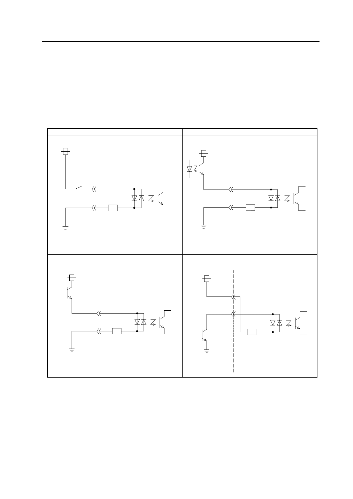
2. Wiring and Connection
2-6 Peripheral control wiring
2-6-1 Input interface
(1) Digital input interface: CN10 to 12
(Special input: 3 points, general-purpose input: 12 points, multi-points orientation command: 12
points, digital speed command: 12 points)
Select from the following.
1) Connecting with contact 2) Connecting with photo coupler
+24V
Current capacity
5.1mA or more
NC(PC) side
4.7KΩ
CES
1 to 3
Drive unit side
+24V
Current
capacity
5.1mA or mor e
NC(PC) side
4.7KΩ
CES
1 to 3
Drive unit side
3) Connecting with open emitter 4) Connecting with open collector
+24V
Current
capacity
5.1mA or
more
+24V
CES 1 to 3
NC(PC) side
CES
1 to 3
4.7KΩ
Drive unit side
Current
capacity
5.1mA or
more
NC(PC) side
4.7KΩ
Drive unit side
(Note 1) A +24V(±10%) power supply is required for this unit. The required maximum power supply capacity is 26W. DC stabilized
(Note 2) Common for dedicated/general-purpose input is CES1, common for digital speed command is CES2, and common for
(Note 3) Filter time constant at the input section is 5 to 15ms.
(Note 4) When running the motor on a trial basis, (when only "machine ready complete", "forward run" and "reverse run" are input
(Note 5) Power supply unit's CN23 is a similar circuit; however , the resistance is not 4.7kΩ but 2kΩ.
power supply must be used here.
multi-point orientation command is CES3. Each command is electrically separated one another.
Thus, when using CES1, 2 or 3, each of them has to be connected to one of the signals (power supply, etc.).
and all the other 24V I/O are not used.), external +24V power supply is exceptionally not necessary; internal +24V power
supply will do. In this case, use CN10-7 pin for +24V, CN10-10 pin for RG (24G).
2 - 23
Page 52

A
(2) Encoder (1024p/rev) input interface
When connecting an encoder, +5V must be supplied from the drive unit side.
Power does not need to be supplied from the NC(PC) side.
(3) Analog input interface
1KΩ
VR1
VR2
2KΩ
VR3
1KΩ
680Ω
B
C
D
2. Wiring and Connection
+15V
Upper speed limit
VR1
setting
VR2 Analog speed setting Override speed setting
Lower speed limit
VR3
setting
A RP (CN8A-6) OR3 (CN8A-16)
B SE1 (CN8A-7) OR2 (CN8A-17)
Analog speed
command input
Override input
Not required
Not required
C SE2 (CN8A-8) OR1 (CN8A-18)
D SES (CN8A-5) ORS (CN8A-15)
Input impedance of input pin B (SE1, OR2):
NC(PC) side Drive unit side
Approx. 10KΩ
(Note 1) The figure above indicates the case of unipolar input. (Bipolar input cannot be created only with the power supply from the
(Note 2) +15V power supply is output from the input pin A (RP, OR3) via the resistance.
(Note 3) Input voltage tolerable value of the input pin B (SE1, OR2) is as follows.
(Note 4) Make sure to use a shielded cable for the cable connecting to each input pin and provide with shield treatment.
(Note 5) If there is a separate analog speed input command (or override input) power supply, connection will be as shown below.
drive unit side.)
SE1: ±12V
OR2: 0 to +12V
(
represents for a shield.)
B
C
D
NC(PC) side
Drive unit side
2 - 24
Page 53

2-6-2 Output interface
(1) External contact output circuit
The drive unit fault output signal FA(CN12-10) and FC(CN12-20) are the outputs.
Use the contacts with the rating indicated below.
24VDC 0.3A or less
Chattering 5ms or less
Compact relay is used. When connecting an inductive load such as relay, preferably use a DC
compact relay, and connect a flywheel diode in parallel with the coil as shown in the figure below.
(2) Open emitter output circuit
The followings are the open emitter outputs.
General-purpose output 1: OUT1 (CN11-7)
General-purpose output 2: OUT2 (CN11-17)
General-purpose output 3: OUT3 (CN11-8)
General-purpose output 4: OUT4 (CN11-18)
General-purpose output 5: OUT5 (CN11-9)
General-purpose output 6: OUT6 (CN11-10)
General-purpose output 7: OUT7 (CN11-20)
General-purpose output 8: OUT8 (CN9A-8)
2. Wiring and Connection
FA(CN12-20)
Flywheel diode
FC(CN12-20)
NC(PC) side Drive unit side
24V
RA
Output transistor rating
M54630P TR array
Tolerable voltage 24VDC or less
Tolerable current 50mA or less
(per 1 output)
24V
+24V(CN10-17)
OUT1 to 8
RG(CN10-10)
2 - 25
RA
NC(PC) side Drive unit side
Page 54

A
(3) Open collector output circuit
The followings are the open collector outputs.
General-purpose output 1C: OUT1C (CN12-7)
General-purpose output 2C: OUT2C (CN12-17)
General-purpose output 3C: OUT3C (CN12-8)
General-purpose output 4C: OUT4C (CN12-18)
General-purpose output 5C: OUT5C (CN12-9)
General-purpose output 6C: OUT6C (CN10-20)
2. Wiring and Connection
Output transistor rating
M54633P TR array
Tolerable voltage 24VDC or less
Tolerable current 50mA or less
(per 1 output)
24V
+24V(CN10-17)
OUT1C to 6C
RG(CN10-10)
NC(PC) side Drive unit side
(Note 1) When using a DC relay externally, connect a flywheel diode in parallel with the coil.
(Note 2) 24V and RG are common for the open emitter and open collector output. Pay attention to the cable size. (24V and RG
consume 60mA only for the spindle drive unit internal circuit.)
(Note 3) When all 8 circuits are used for the open emitter output, the total current has to be no more than 350mA.
(Note 4) High-frequency noise due to chopper affects this output signal and may cause the reception side of circuit for this signal to
malfunction. In such a case, use a shielded cable for the output signal connection cable, and connect one side of the
shielded cable to the spindle drive unit CN10-10 pin and the other one to the 24V power supply's ground.
24V
RA
(4) Pulse feedback output
Pulse feedback output is described as shown in the figure below.
(The output signal is equivalent of RS485.)
SYA(CN8A-2)
-phase
SYA*(CN8A-12)
SYB(CN8A-3)
SYB*(CN8A-13)
SYZ(CN8A-4)
SYZ*(CN8A-14)
GND(CN8A-1)
(Note) Use an output IC equivalent of Motorola MC3487.
2 - 26
A-phase
B-phase
B-phase
Z-phase
Z-phase
NC(PC) side Drive unit side
Page 55

2. Wiring and Connection
2-6-3 Spindle coil changeover
There are spindle motors capable of coil changeover control, which enables favorable characteristics to
be attained from low speeds to high speeds by changing two types of coils.
(1) Coil changeover control
The speed at which to change the coils is detected by the spindle drive according to the value set
with spindle parameter SP020. This is conveyed to the NC or PC with a speed detection (SD) signal.
The NC or PC judges the other conditions (coil fixed, etc.), and issue a coil changeover command
to the spindle drive with the L coil selection command (LCS).
To prevent the contactor from varying, the hysteresis set with SP047 is applied on the speed when
changing from the low-speed coil to the high-speed coil and the high-speed coil to the low-speed
coil.
6000
Spindle motor speed
(r/min)
Speed detection (SD1) [SPA→NC(PC)]
L coil selection command (LCS) [NC(PC)
Changing coil (MKC)
In L coil selection signal (LCSA) [SPA
Contactor changeover
[SPA→NC(PC)]
→NC(PC)]
Spindle motor coil changeover control
4000
2000
(SP020+SP047)
0
→SPA]
Low-speed coil High-speed coil Low-speed coil
No. Abbrev. Parameter name Description Setting range
SP020 SDTS* Speed detection
SP047 SDTR* Speed detection
SP129
to
SP140
SP141
to
SP154
HI01
to
HI12
H01e
to
H01c
set value
reset value
General-purpose
input selection
General-purpose
output selection
Set the motor speed of which speed detection 1 output is
performed. The setting value is determined by Mitsubishi
according to the specifications of coil changeover motor.
Set the reset hysteresis width for a speed detection set
value defined in SP020 (SDTS).
Set the general-purpose input signals IN1 to IN12 as to
which function they should have. To have the coil
changeover function, set "18" (L coil selection command) in
one of those signals.
Set the general-purpose output signals OUT1 to OUT8
(open emitter) or OUT1C to OUT6C (open collector) as to
which function they should have. Set "18" (L coil selected
signal) in one of those signals. Also, set "16" (changing coil)
in another signal as required.
0 to 32767
(r/min)
0 to 1000
(r/min)
0 to 13
14 to 9
0 to 4
7 to 23
SP020
Time
Standard
value
Depends on
the motor to
be used.
Lath: 300
Machining:
100
-
-
2 - 27
Page 56

2. Wiring and Connection
(2) Protective functions
[1] Base shutoff after a winding changeover
When the L-coil selection command (LCS) is used to perform low-speed winding → high-speed
winding switching, or vice-versa, this base is shut off during contactor operation time in order to
protect the spindle drive unit's main circuit. This base shutoff time is determined by the "Winding
changeover base shutoff timer" (SP059) setting. The standard time setting should be used, as a
shorter time can cause contactor burn damage.
(Refer to 4-2-2 (4) "Spindle control output 4" Coil changing (bit 6) for details.)
No. Abbrev. Parameter name Description Setting range
SP059 MKT* Winding
changeover base
shut-off timer
Set the base shut-off time for contactor switching at coil
changeover.
Note that the contactor may be damaged with burning if the
value of this parameter is too small.
50 to 10000
[2] Current limit after coil changeover
Following a coil changeover, the current is limited (SP061) for the period specified by the
current limit timer (SP060) in order to stabilize control. When the synchronous tap control is
executed immediately after the coil changeover, the output current is limited to the value set in
SP061, therefore apply the sequence to execute the position control after the current limit is
cancelled.
No. Abbrev. Parameter name Description Setting range
SP060 MKT2* Current limit timer
after coil
changeover
SP061 MKIL* Current limit value
after coil
changeover
Set the current limit time to be taken after completion of
contactor switching at coil changeover.
Set the current limit value during a period defined in SP060
(MKT2) after completion of contactor switching at coil
changeover.
0 to 120 (%) 75
(ms)
0 to 10000
(ms)
Standard
value
150
Standard
value
500
2 - 28
Page 57

p
(3) Wiring
The illustration below shows the 2 types of changeover that occur after a coil changeover, (a) Y
(star) – ∆ (delta) changeover, and (b) Y (star) – Y (star) changeover. As shown in (c), one of the
contactors (MC1 or MC2) is turned ON and the other is turned OFF at all of the coil changeover
control circuits.
U
V
W
Spindle drive unit
terminal block
2. Wiring and Connection
U
V
W
MC2
MC1
MC1: Contactor to connect low-speed coil (Y-connection)
MC2: Contactor to connect high-speed coil (
∆-connection)
X
Y
Z
S
indle motor
(a) Y (star) - ∆ (delta) changeover circuit
U
V
W
Spindle drive unit
terminal block
MC1: Contactor to connect low-speed coil (1st Y-connection)
MC2: Contactor to connect high-speed coil (2nd Y-connection)
(b) Y (star) - Y (star) changeover circuit
MDS-C1-SPA
MC1
MC2
U1
V1
W1
U2
V2
W2
Spindle motor
RA
CN10-17
OUT1 to
OUT8
RA
CN10-10
Connect the signal wire s ide of coil RA with the output pin which the In L coil selection sig nal is pro vide d to.
CN10-17
RA
OUT1C to
OUT6C
CN10-10
(c) Coil changeover control circuit (common)
Coil changeover relay control circuit
S
T
2 - 29
MC
MC
SK
MC
RA
MC
SK
Page 58

L
L
2. Wiring and Connection
2-6-4 Wiring of an external emergency stop
(1) External emergency stop setting
Besides the emergency stop input from the NC or PC to spindle drive unit, double-protection when
an emergency stop occurs can be provided by directly inputting an external emergency stop to the
CN23 connector on the power supply unit. Even if the emergency stop is not input from CNC for
some reason, the contactors will be shut off by the external emergency stop input from CN23
connector on the power supply unit.
[1] Connection
NC
Emergency
stop
Alarm
MDS-C1-SPA
IN1 to IN12
OUT1 to OUT8
OUT1C to OUT6C
CN4
Emergency
stop
Alarm
SH21
FCUA-R000
MDS-C1-CV
CN4
MC1
MC1
11
21
Contacto r shut o ff
command
External emergency stop input
1 EMG1
2 NC
3 EMG2
[2] Setting
When using the external emergency stop, the rotary switch on the front of the power supply unit
and the parameter (PTYP) of drive unit that controls the power supply must be set.
• Rotary switch setting: 4
• Parameter setting: Add "0040" to the setting of PTYP (SP041).
Parameter settings
No. Abbrev. Parameter name Descriptions
SP041 PTYP Power supply
type
When external emergency stop is validated, 0040 [hex] is added to PTYP for the drive unit
connected to the power supply unit.
The emergency stop signal input to the CNC side cannot be used as a substitute
CAUTION
for the external emergency stop function (CN23).
CN23
2 - 30
Page 59

2. Wiring and Connection
(2) Operation sequences of CN23 external emergency stop function
If only external emergency stop is input when external emergency stop valid is set in the
parameters (the emergency stop is not input in the spindle drive unit), an "In external emergency
stop" (warning EA) will be detected. At this time, the spindle drive unit does not enter an emergency
stop status. (There will be no deceleration control.)
If an emergency stop is not issued for the spindle drive unit within 30 seconds and the setting time
of SP055 after the external emergency stop is input, the power supply unit outputs contactor shutoff
signal (MC1), and then it shuts off the contactors, and a power supply error (alarm 6F) is detected
simultaneously. If the emergency stop is input within 30 seconds and the setting time of SP055, the
warning EA replaces the "In emergency stop" (warning E7). A normal emergency stop status will
result if the contactor shutoff command is further input.
When the setting value of SP192 is set to "2" or "3", a power supply error (alarm 6F) will occur even
if the emergency stop is input within 30 seconds and the setting time of SP055.
Ready ON is possible even if CN23, an external emergency stop has been input when the
emergency stop is canceled, but a power supply error (alarm 6F) will occur after 30 seconds.
External emergency stop input
(EMGX)
Main emergency stop input
(EMG)
Motor speed
Contactor control command
Contactor control terminal (MC)
Servo drive unit status display
OFF
ON
OFF
ON
Deceleration stop
0
ON
OFF
ON
OFF
dx E7EA
Setting time of SP055
30 second or less
Cx→dx
External emergency stop input
(EMGX)
Main emergency stop input
(EMG)
Motor speed
Contactor control command
Con tactor control terminal (MC)
Servo drive unit status display
(a) When the emergency stop is not input, and the contactor shut-off command is not input
(b) When the emergency stop input is not selected for the general-purpose input of spindle drive unit
External emergency stop input sequences
OFF
ON
OFF
ON
0
ON
OFF
ON
OFF
dx 6F EA
0 30
Coast to stop
2 - 31
Page 60
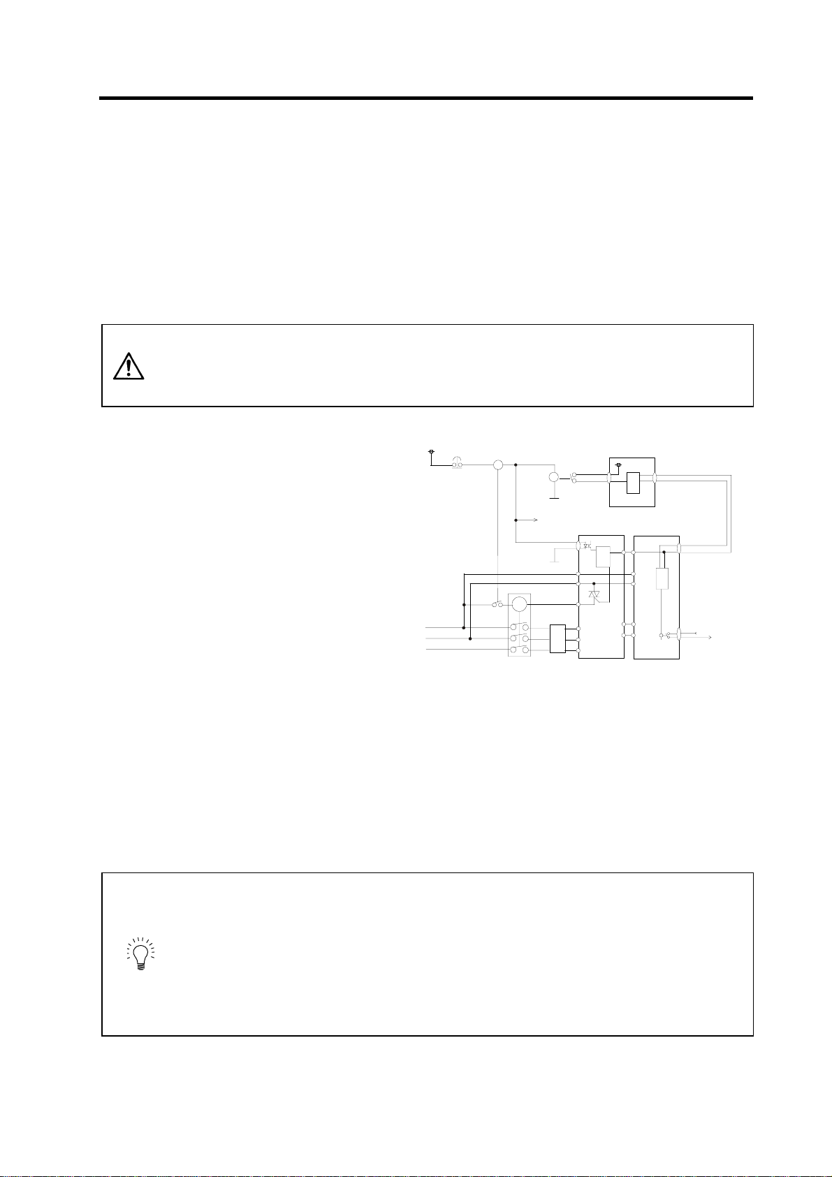
(3) Example of emergency stop circuit
[1] Outline of function
The power supply unit's external emergency stop can be validated by wiring to the CN23
connector, and setting the parameters and rotary switch. If the emergency stop cannot be
processed and the external contractor cannot be shut off (due to a fault) by the spindle drive unit,
the external contactor can be shut off by the power supply unit instead of the spindle drive unit.
At this time, the spindle motor will coast to stop.
EN60204-1 Category 1 can be basically complied with by inputting the external emergency stop
and installing contactor.
1. The power supply unit external emergency stop function is a function that
assists the NC emergency stop.
CAUTION
2. It will take 30 seconds for the external contactor to function after the
emergency stop is input to CN23. (This time is fixed.)
[2] Outline of function
The emergency stop is a signal used
to stop the machine in an emergency.
This is connected to the NC unit. Wire
to the power supply unit when
necessary.
The servo/spindle unit will be
decelerated and controlled by the
software according to the emergency
stop command issued from the NC
unit. (The deceleration control
depends on a parameter setting.)
The diagram on the right shows an
example of the emergency stop circuit
(EN60204-1 Category 0 stop) in which
an off delay timer (TM1) is installed as
a power shutoff method independent from the NC emergency stop input. The required safety
category may be high depending on the machine and the Safety Standards may not be met. Thus,
always pay special attention when selecting the parts and designing the circuit.
[3] Setting the off delay timer (TM1) time
Set the TM1 operation time so that it functions after it has been confirmed that all axes have
stopped. If the set time is too short, the spindle motor will coast to a stop.
Provide a mechanism that shuts off the power even if the NC system fails.
2. Wiring and Connection
TM1
External
Emergency
Switch
R
tm ≥ All axes stop time
MC
External
Contactor
RA1
R
GND
MBR*
GND
AC Reactor
CN23
EMG
Power Supply
Unit
CUP
&
ASIC
L11
L21
MC-OFF*
MC1
L1
L2
L3
CN4
NC Unit
CUP
&
ASIC
Servo/Spindle
CN4
L11
L21
P
N
SV1/2
Drive Unit
CUP
&
ASIC
Hardware Emergency
CN1A/B
Software Emergency
CN20
MBR*
Motor
Brake
Stop Categories in EN60204-1
Category 0: The power is instantly shut off using machine parts.
Category 1: The drive section is stopped with the control (hardware/software
or communication network), and then the power is instantly shut
POINT
off using machine parts.
(Caution) Refer to the Standards for details.
Refer to Section 9.2.5.4.2 in EN60204-1: Safety of Machinery
Electrical Equipment of Machines – Part 1.
2 - 32
Page 61

3. Setup
3-1 Initial setup........................................................................................................................................ 3-2
3-1-1 Setting the rotary switch ............................................................................................................ 3-2
3-1-2 Transition of LED display after power is turned ON .................................................................. 3-3
3-2 Setting the initial parameters for the spindle drive unit..................................................................... 3-4
3-2-1 Parameter setting method ......................................................................................................... 3-4
3-2-2 List of spindle parameters.......................................................................................................... 3-6
3-3 Initial adjustment of the spindle PLG.............................................................................................. 3-26
3-3-1 Adjusting the PLG installation.................................................................................................. 3-26
3 - 1
Page 62

3. Setup
3-1 Initial setup
3-1-1 Setting the rotary switch
Before turning on the power, the settings of the spindle drive unit and power supply unit's rotary
switches must be confirmed and changed.
Setting the
rotary switch
0
1
2 Setting prohibited
3
4
5
6
7
8
9
A Setting prohibited
B
C
D
E
F
Spindle drive unit
(MDS-C1-SPA)
5 B
4 C
3 D
Setting the MDS-C1- SPA Setting the MDS-C1-CV
Apply this setting when the power is
turned ON.
Set when the parameter setting is
confirmed and changed.
Setting prohibited
7 9
6 A
2 E
1 F
8
0
Power supply unit
(MDS-C1-CV)
Details
External emergency stop
External emergency stop valid
8
7 9
6 A
5 B
4 C
3 D
2 E
1 F
0
invalid
(Used CN23)
Even if multiple spindle drive units are used for the same machine, set "0" for
POINT
the settings of all spindle drive units' rotary switches before the power is turned
ON.
3 - 2
Page 63

Dri
3. Setup
3-1-2 Transition of LED display after power is turned ON
The spindle drive unit and the power supply unit power have been turned ON, each unit will
automatically execute self-diagnosis and initial settings for operation, etc. The LEDs on the front of the
units will change as shown below according to the progression of these processes.
If an alarm occurs, the alarm No. will appear on the LEDs. Refer to "5-1-1 LED display when alarm or
warning occurs" for details on the alarm displays.
Reset signal
ON state
Reset signal
LED display
OFF
ve units
NC power ON
Initializing
Power supply unit
LED display
Initializing
Initializing completed
Ready OFF state
In the middle of Ready ON
(charge completed)
Ready ON state
Emergency stop state
(In selecting emergency stop input)
Servo ON state
Reset signal
ON
In selecting reset
signal input
The LED will alternate between
F1 → E7 → not lit.
Servo OFF sate
Repeats lighting and going out.
(1st axis in the display example)
Emergency stop
Ready OFF
When starting the spindle system, be sure that the machine ready completion
CAUTION
input (Ready signal) is turned OFF, or that the emergency stop signal is
selected and input.
3 - 3
Page 64

3. Setup
3-2 Setting the initial parameters for the spindle drive unit
The parameters of spindle drive unit must be set before the spindle system can be started up. Basic
settings have been provided in shipping. Therefore, for parameters required to be changed individually,
they are input with the rotary switch and push button of the drive unit or the personal computer.
3-2-1 Parameter setting method
There are two methods of parameter setting as shown below.
(a) Setting by the personal computer
(b) Setting by the spindle drive unit 7-segment, rotary switch and push-buttons
The method (b) is explained in this section.
(1) Layout of display unit
Open the cover on the right side of the LED located in the upper part of the spindle drive unit. The
following switch and push-buttons are found there.
Rotary SW
UP
Rotary SW : Used to change the display mode.
SET
DOWN
(2) Parameter setting method
1. Change the parameter in the state where the start signal is not input.
2. All the parameter Nos. have to be converted into HEX when input. The
CAUTION
3. When the parameter is changed with this method, always turn the spindle
1) Turn the drive unit main power supply ON.
2) Set the rotary SW to "1".
At this time, main/sub is displayed on the left side of the spindle drive unit 7-segment LED, and
the upper one digit of the parameter No. is displayed on the other side.
[1] Set the upper digit of parameter No. with UP/DOWN buttons.
Set "0" for the parameter No. SP255 or lower, set "1" for the parameter No. SP256 or higher.
[2] Switch Main/Sub with SET button. Main and Sub switch every time the SET button is pressed.
When "1" is displayed on the left side of LED, "Main" is selected; when "2" is displayed, "Sub"
is selected. Set at the main side for all the specifications other than 1A2M.
UP button : Used to increase the data value.
DOWN button : Used to decrease the data value.
SET button : Used to start/finish changing the parameter setting value.
targeted setting data, whether if it is DEC, must also be converted into
HEX. (If the setting value is HEX, set the value as it is.)
drive unit's power ON → OFF, or turn the alarm reset signal ON → OFF to
validate the parameter.
3 - 4
Page 65

3. Setup
3) Set the rotary SW to "2".
At this time, the spindle drive unit 7-segment LED indicates the lower two digits of parameter No.
Use the UP/DOWN buttons to set the lower two digits of the parameter No. Keep the button
pressed to expedite the operation.
(Setting example)
Parameter No.
LED setting
value
SP001 1
SP010 A
SP129 81
SP255 FF
SP320 40 (Note that, however, the rotary SW is "1" at this time and so
"1" must be set on the right side of LED.)
4) Set the rotary SW to "3".
At this time, the spindle drive unit 7-segment LED indicates the upper two digits of the
parameter setting value.
[1] The display lamp starts flashing rapidly when the SET button is pressed.
[2] Use the UP/DOWN button to change the setting value. Keep the button pressed to expedite
the operation.
[3] Press the SET button once again when reaching the target setting value. The flashing of the
display lamp slows down.
5) Set the rotary SW to "4".
At this time, the spindle drive unit 7-segment LED indicates the lower two digits of the parameter
setting value.
[1] The display lamp starts flashing rapidly when the SET button is pressed.
[2] Use the UP/DOWN button to change the setting value. Keep the button pressed to expedite
the operation.
[3] Press the SET button once again when reaching the target setting value. The flashing of the
display lamp slows down.
(Setting example)
Target setting value (DEC) Setting value - Rotary SW "3" Setting value - Rotary SW "4"
1
0 1
10 0 A
100 0 64
1000 3 E8
10000 27 10
32767 7F FF
This is the end of setting. Set the rotary SW back to "0" and turn the drive unit's power ON again or
enter the reset input.
3 - 5
Page 66

3. Setup
3-2-2 List of spindle parameters
These parameters are sent to the spindle drive unit when the NC power is turned ON. The standard
parameters are designated with the "Spindle parameter setting list" enclosed when the spindle motor is
delivered. There may be cases when the machine specifications are unclear, so the parameters
determined by the machine specifications should be confirmed by the user.
No. Abbr. Parameter name Details
SP001 PGM*
SP002 PGE*
SP003 Not used. Set "0". 0 0
SP004 OINP*
SP005 OSP
SP006 CSP*
SP007 OPST*
SP008
SP009 Not used. Set "0". 0 0
SP010 Not used. Set "0". 0 0
SP011 Not used. Set "0". 0 0
SP012 Not used. Set "0". 0 0
SP013 Not used. Set "0". 0 0
SP014 Not used. Set "0". 0 0
SP015 Not used. Set "0". 0 0
SP016 Not used. Set "0". 0 0
Parameters having an abbreviation with "*" (PGM*, etc.) are validated right after the settings are changed by the personal computer,
without turning the spindle drive unit's power ON and OFF.
Magnetic sensor, motor
PLG orientation position
loop gain
Encoder orientation
position loop gain
Orientation in-position
width
Orientation mode
speed clamp value
Orientation mode
deceleration rate
Position shift amount for
orientation
The orientation time will be shorter when the value is
increased, and the servo rigidity will increase. On the
other hand, the vibration will increase, and the machine
will sway easily.
The orientation time will be shorter when the value is
increased, and the servo rigidity will increase. On the
other hand, the vibration will increase, and the machine
will sway easily.
Set the position error range in which an orientation
completion signal is output.
Set the motor speed limit value to be used when the
speed loop is changed to the position loop in orientation
mode.
When this parameter is set to "0", SP017 (TSP) becomes
the limit value.
In the spindle side speed clamp valid
(SP097:SPEC0-bit4=1), the speed limit value will be the
spindle speed instead of the motor speed.
As the set value is larger, the orientation time becomes
shorter. However, the machine becomes likely to
overshoot.
Set the stop position for orientation.
(1) Motor PLG and spindle side detector
Set a value obtained by dividing 360° by 4096.
(2) Magnetic sensor orientation
Divide -5°C to +5° by 1024, and set 0° as "0".
Not used. Set
"0".
Setting range
(Unit)
0 to 1000
(0.1 rad/s)
0 to 1000
(0.1 rad/s)
1 to 2880
(1/16°)
0 to 32767
(r/min)
1 to 1000 20
(1)
0 to 4095
(2)
-512 to 512
0 0
Standard
setting
100
100
16
0
0
3 - 6
Page 67

3. Setup
No. Abbr. Parameter name Details
SP017 TSP Maximum motor speed
SP018 ZSP Motor zero speed
SP019 CSN1 Speed cushion 1
SP020 SDTS
SP021 TLM1* Torque limit 1
SP022
SP023 VGNI1
SP024 Not used. Set "0". 0 0
SP025 GRA1
SP026 GRA2
SP027 GRA3
SP028 GRA4
SP029 GRB1
SP030 GRB2
SP031 GRB3
SP032 GRB4
Parameters having an abbreviation with "*" (TLM1*, etc.) are validated right after the settings are changed by the personal
computer, without turning the spindle drive unit's power ON and OFF.
VGNP1
Speed detection set
value
Speed loop gain
proportional term under
speed control
Speed loop gain integral
term under speed
control
Spindle gear teeth count 1 Set the number of gear teeth of the spindle
Spindle gear teeth count 2 Set the number of gear teeth of the spindle
Spindle gear teeth count 3 Set the number of gear teeth of the spindle
Spindle gear teeth count 4 Set the number of gear teeth of the spindle
Motor shaft gear teeth
count 1
Motor shaft gear teeth
count 2
Motor shaft gear teeth
count 3
Motor shaft gear teeth
count 4
Set the maximum spindle motor speed. 1 to 32767
Set the motor speed for which zero-speed signal output
is performed.
Set the time constant for a speed command from "0" to
the maximum speed.
(This parameter is invalid when the S analog
synchronous tapping is valid.)
Set the motor speed for which speed detection output is
performed.
Usually, the setting value is 10% of SP017 (TSP).
Set the torque limit rate when the torque limit signal 1 is
assigned to the general-purpose input and the input is
turned ON.
Set the speed loop proportional gain in speed control
mode. When the gain is increased, response is
improved but vibration and sound become larger.
Set the speed loop integral gain in speed control mode.
Normally, this is set so that the ratio in respect to SP022
(VGNP1) is approximately constant.
corresponding to gear 000.
corresponding to gear 001.
corresponding to gear 010.
corresponding to gear 011.
Set the number of gear teeth of the motor shaft
corresponding to gear 000.
Set the number of gear teeth of the motor shaft
corresponding to gear 001.
Set the number of gear teeth of the motor shaft
corresponding to gear 010.
Set the number of gear teeth of the motor shaft
corresponding to gear 011.
Setting range
(Unit)
(r/min)
1 to 1000
(r/min)
1 to 32767
(10 ms)
0 to 32767
(r/min)
0 to 120 (%) 10
0 to 1000 63
0 to 1000 60
1 to 32767 1
1 to 32767 1
1 to 32767 1
1 to 32767 1
1 to 32767 1
1 to 32767 1
1 to 32767 1
1 to 32767 1
Standard
setting
6000
50
30
600
3 - 7
Page 68

3. Setup
No. Abbr. Parameter name Details
SP033 SFNC1 Spindle function 1
(Note ) Set 0 if there is no particular explanation for the bit.
SP034 SFNC2 Spindle function 2
(Note ) Set 0 if there is no particular explanation for the bit.
F E D C B A 9 8 7 6 5 4 3 2 1 0
pychg
poff hzs ront
bit Meaning when set to 0 Meaning when set to 1 Standard
0 1a2m 1 drive unit 2 motor function: Invalid 1 drive unit 2 motor function: Valid 0
1 dflt Default motor: Main Default motor: Sub 0
2 sftk Without SF-TK card With SF-TK card 0
3 0
4 0
5 0
6 pyoff This is set by Mitsubishi. Set to "0" unless particularly designated.
7 0
8 0
9 pycal (Conventional specifications)
A 0
B 0
C ront Normal ready ON High-speed ready ON 0
D 0
Ehzs
F poff
Gate OFF by high-cycle zero speed
invalid
Contactor hold at NC power OFF
invalid
pycal
pyst pyoff sftk dflt
High-speed rate deceleration
method valid for minimum excitation
rate
Gate OFF by high-cycle zero speed
valid
Contactor hold at NC power OFF
valid
F E D C B A 9 8 7 6 5 4 3 2 1 0
bit Meaning when set to 0 Meaning when set to 1 Standard
0 mtsl Special motor constant invalid Special motor constant setting valid 0
1invm
2 mkch Coil switch function invalid Coil switch function valid 0
3 mkc2 This is set by Mitsubishi. Set to "0" unless particularly designated. 0
4 0
5 0
6 0
7 0
8 0
9 0
A 0
B 0
C 0
D 0
E 0
F 0
A general-purpose motor FV control
invalid
A general-purpose motor FV control
valid
mkc2 mkch
1a2m
0
0
0
invm mtsl
0
3 - 8
Page 69

3. Setup
No. Abbr. Parameter name Details
SP035 SFNC3 Spindle function 3
SP036 SFNC4 Spindle function 4
FEDCBA98765 4 3 2 10
lbsd hbsdlwidhwid
bit Meaning when set to 0 Meaning when set to 1 Standard
0hwid
1lwid
2 hbsd H-coil base slide invalid H-coil base slide valid 0
3 lbsd L-coil base slide invalid L-coil base slide valid 0
4 0
5 0
6 0
7 0
8 0
9 0
A 0
B 0
C 0
D 0
E 0
F 0
H-coil wide-range constant output
invalid
L-coil wide-range constant output
invalid
(Note) Set 0 if there is no particular explanation for the bit.
FEDCBA98765 4 3 2 10
dslm
bit Meaning when set to 0 Meaning when set to 1 Standard
0 plg1 PLG of motor 1 valid PLG of motor 1 invalid 0
1 plg2 PLG of motor 2 valid PLG of motor 2 invalid 0
2 mag1 MAG of motor 1 valid MAG of motor 1 invalid 0
3 mag2 MAG of motor 2 valid MAG of motor 2 invalid 0
4 enc1 ENC of motor 1 valid ENC of motor 1 invalid 0
5 enc2 ENC of motor 2 valid ENC of motor 2 invalid 0
6 0
7 0
8 dssm Speedometer output valid Speedometer output invalid 0
9 dslm Load meter output valid Load meter output invalid 0
A 0
B 0
C 0
D 0
E 0
F 0
dssm
(Note) Set 0 if there is no particular explanation for the bit.
H-coil wide-range constant output
valid
L-coil wide-range constant output
valid
enc2 enc1
mag2 mag1
0
0
plg2 plg1
3 - 9
Page 70

3. Setup
No. Abbr. Parameter name Details
SP037 SFNC5 Spindle function 5
SP038 SFNC6 Spindle function 6
FEDCBA98765 4 3 2 10
dplg ospcl
bit Meaning when set to 0 Meaning when set to 1 Standard
0 enco Encoder orientation invalid Encoder orientation valid 0
1 mago Magnetic sensor orientation invalid Magnetic sensor orientation valid 0
2 plgo PLG orientation invalid PLG orientation valid 0
3 0
4 0
5 0
6 0
7 psdir Position shift standard Position shift reverse direction 0
8 nosg
9 nsno No-signal detection valid No-signal detection invalid 0
A noplg
B 0
C 0
D ospcl
E dplg This is set by Mitsubishi. Set to "0" unless particularly designated. 0
F 0
No-signal detection type
(Always monitoring)
Constant monitor of PLG-Z phase
no-signal invalid
Orientation speed clamp
motor speed setting
noplg
nsno nosg psdir plgo
(Note 1) For bit0 to 2, do not set two bits or more to "1" at the same time.
(Note 2) Set 0 if there is no particular explanation for the bit.
FEDCBA98765 4 3 2 10
oplp lmx iqsv
bit Meaning when set to 0 Meaning when set to 1 Standard
0alty
1 0
2 0
3plg2
4 Tdn This is used by Mitsubishi. Set to "0" unless particularly designated. 0
5 0
6 orm Orientation start memo invalid Orientation start memo valid 0
7 vfbs This is set by Mitsubishi. Set to "0" unless particularly designated.
8 0
9 0
A lmnp This is set by Mitsubishi. Set to "0" unless particularly designated.
Bdcsn
C 0
DIqsv
Elmx
F oplp Open loop operation invalid Open loop operation valid 0
dcsn lmnp vfbs orm Tdn plg2 alty
Deceleration stop during special
alarm invalid
Semi-closed pulse signal output×2
invalid
Dual cushion during acceleration/
deceleration valid
This is set by Mitsubishi. Set to "0" unless particularly designated
(Note) Set 0 if there is no particular explanation for the bit.
No-signal detection valid only in
position loop or orientation-mode
Constant monitor of PLG-Z phase
no-signal valid
Orientation speed clamp
spindle speed setting
Deceleration stop during special
alarm valid
Semi-closed pulse signal output×2
valid
Dual cushion during acceleration/
deceleration invalid
mago
enco
0
0
0
0
0
0
3 - 10
Page 71

3. Setup
No. Abbr. Parameter name Details
Setting Unit capacity Setting Unit capacity
0000 --- 0010 MDS-B-SPA-550
0001 MDS-B-SPA-075 0011 ---
0002 MDS-B-SPA -15 0012 ---
0003 MDS-B-SPA -22 0013 ---
0004 MDS-B-SPA -37 0014 ---
0005 MDS-C1-SPA-55 0015 ---
SP039 ATYP Drive unit type 0006 MDS-C1-SPA-75 0016 --- 0000 to FFFF 0000
0007 MDS-C1-SPA-110 0017 ---
0008 MDS-C1-SPA-150 0018 ---
0009 MDS-C1-SPA-185 0019 ---
000A MDS-C1-SPA-220 001A ---
000B MDS-C1-SPA-260 001B ---
000C MDS-C1-SPA-300 001C ---
000D MDS-B-SPA -370 001D ---
000E MDS-B-SPA -450 001E ---
000F MDS-B-SPA -04 001F ---
Setting Motor name
0000 --- --- ---
0001 SJ-2.2A 10000 r/min MDS-B-SPA -22
0002 SJ-3.7A 10000 r/min MDS-B-SPA -37
0003 SJ-5.5A 8000 r/min MDS-C1-SPA-55
0004 SJ-7.5A 8000 r/min MDS-C1-SPA-75
0005 SJ-11A 6000 r/min MDS-C1-SPA-110
0006 SJ-15A 6000 r/min MDS-C1-SPA-150
0007 SJ-18.5A 6000 r/min MDS-C1-SPA-185
0008 SJ-22A 4500 r/min MDS-C1-SPA-220
0009 SJ-26A 4500 r/min MDS-C1-SPA-260
SP040 MTYP Motor type 000A SJ-30A 4500 r/min MDS-C1-SPA-300 0000 to FFFF 0000
000B --- --- ---
000C --- --- ---
000D --- --- ---
000E --- --- ---
000F --- --- ---
0010 --- --- ---
0011 SJ-N0.75A 10000 r/min MDS-B-SPA-075
0012 SJ-N1.5A 10000 r/min MDS-B-SPA-15
0013 SJ-N2.2A 10000 r/min MDS-B-SPA-22
0014 SJ-N3.7A 10000 r/min MDS-B-SPA-37
0015 SJ-N5.5A 8000 r/min MDS-C1-SPA-55
0016 SJ-N7.5A 8000 r/min MDS-C1-SPA-75
0017 --- --- ---
0018 --- --- ---
0019 --- --- ---
001A --- --- ---
001B SJ-J2.2A 10000 r/min MDS-B-SPA-22
001C SJ-J3.7A 10000 r/min MDS-B-SPA-37
001D SJ-J5.5A 8000 r/min MDS-C1-SPA-55
001E SJ-J7.5A 8000 r/min MDS-C1-SPA-75
001F --- --- ---
Set the spindle drive unit's capacity type.
This parameter is valid when SP034 (SFNC2)/bit0 is set
to "0". (Old type of motor)
Set the appropriate motor number from the standard
motors listed below.
Maximum
speed
(HEX setting)
(HEX setting)
Corresponding
drive unit
Setting range
(Unit)
Standard
setting
3 - 11
Page 72

3. Setup
No. Abbr. Parameter name Details
Setting range
(Unit)
SP041 PTYP Power supply type
F E D C B A 9 8 7 6 5 4 3 2 1 0
amp rtyp ptyp
bit Explanation
0
1
2
3
4
5
6
7
When the CN4 connector of the drive unit and the CN4 or CN9 connector
of the power supply are connected, setting below is necessary.
To validate the external emergency stop function, add 40h.
Setting 0x 1x 2x 3x 4x 5x 6x 7x 8x
ptyp
x0 Not used CV-300
x1 CV-110 CR-10
x2 CV-220 CR-15
x3 CR-22
x4 CV-37 CR-37
x5 CV-150
x6 CV-55 CV-260 CR-55
x7 CV-370
x8 CV-75 CR-75
x9 CV-185 CR-90
MDS-B-
CVE-450
MDS-B-
CVE-550
8Set the regenerative resistor type when MDS-A-CR is used.
9 Setting Regenerative resistor model name
rtyp
A0
B
2
3
4
5
6
7
8
9
A~F
C
D
amp
E
F
MDS-C1-CV (Setting when using power supply regeneration)
1
GZG200W260HMJ (Note)
GZG300W130HMJ×2
MR-RB30
MR-RB50
GZG200W200HMJ×3
GZG300W200HMJ×3
R-UNIT-1
R-UNIT-2
R-UNIT-3
No setting
(Note) When MDS-B-SPA-370, 450 or 550 is used, set "0" even if power
regeneration type is applied.
Always set to "0".
Resistance
value
26Ω
26Ω
13Ω
13Ω
6.7Ω
6.7Ω
30Ω
15Ω
15Ω
SP042 Not used. Set "0". 0 0
SP043 Not used. Set "0". 0 0
SP044 Not used. Set "0". 0 0
Set the cycle to add the increment values in the dual
cushion process.
SP045 CSNT* Dual cushion timer
When this setting value is increased, the dual cushion will
0 to 1000 (ms) 0
increase, and the changes in the speed during
acceleration/deceleration will become gradual.
Parameters having an abbreviation with "*" (CSNT*, etc.) are validated right after the settings are changed by the personal
computer, without turning the spindle drive unit's power ON and OFF.
Standard
Capacity
150W
300W
500W
350W
500W
700W
700W
2100W
setting
80W
3 - 12
Page 73

3. Setup
No. Abbr. Parameter name Details
For an acceleration/deceleration time constant defined in
SP019 (CSN1) , this parameter is used to provide smooth
SP046 CSN2
SP047 SDTR
SP048 SUT Speed reach range
SP049 TLM2* Torque limit 2
SP050 TLM3* Torque limit 3
SP051 TLM4* Torque limit 4
SP052 TLM5* Torque limit 5
SP053 TLM6* Torque limit 6
SP054 TLM7* Torque limit 7
SP055 SETM
SP056 PYVR*
SP057 STOD*
SP058 Not used. Set "0". 0 0
SP059 MKT*
SP060 MKT2*
SP061 MKIL*
SP062 Not used. Set to "0". 0 0
SP063 OLT*
SP064 OLL*
SP065 VCGN1*
Speed command dual
cushion
Speed detection reset
value
Excessive speed
deviation timer
Variable excitation
(min value)
Constant → transition
judgment value
Winding changeover
base shut-off timer
Current limit timer after
coil changeover
Current limit value after
coil changeover
Overload alarm detection
time
Overload alarm detection
level
Target value of variable
speed loop proportional
gain
movement only at the start of acceleration/deceleration.
As the value of this parameter is smaller, it moves
smoother but the acceleration/deceleration time becomes
longer.
To make this parameter invalid, set "0".
Set the reset hysteresis width for a speed detection set
value defined in SP020 (SDTS).
Set the speed deviation rate with respect to the
commanded speed for output of the speed reach signal.
Set the torque limit rate when the torque limit signal 1, 2 or
1, 2, 3 are assigned to the general-purpose input and only
the torque limit 2 is turned ON.
Set the torque limit rate when the torque limit signal 1, 2 or
1, 2, 3 are assigned to the general-purpose input and the
torque limit 1, 2 are turned ON.
Set the torque limit rate when the torque limit signal 1, 2, 3
are assigned to the general-purpose input and the torque
limit 3 is turned ON.
Set the torque limit rate when the torque limit signal 1, 2, 3
are assigned to the general-purpose input and the torque
limit 1, 3 are turned ON.
Set the torque limit rate when the torque limit signal 1, 2, 3
are assigned to the general-purpose input and the torque
limit 2, 3 are turned ON.
Set the torque limit rate when the torque limit signal 1, 2, 3
are assigned to the general-purpose input and the torque
limit 1, 2, 3 are all turned ON.
Set the timer value until the excessive speed deviation
alarm is output.
The value of this parameter should be longer than the
acceleration/deceleration time.
Set the minimum value of the variable excitation rate.
Select a smaller value when gear noise is too high.
Set the value for judging when changing the speed
command from a constant to acceleration/deceleration.
When "0" is set, judge the speed with 12 r/min.
Motor maximum speed under 10000r/min: Set “7”.
Motor maximum speed 10000r/min or more: Set “40”.
Note that “20” is set when using some of the ultra
high-speed motors.
Set the base shut-off time for contactor switching at coil
changeover.
Note that the contactor may be damaged with burning if
the value of this parameter is too small.
Set the current limit time to be taken after completion of
contactor switching at coil changeover.
Set the current limit value during a period defined in
SP060 (MKT2) after completion of contactor switching at
coil changeover.
Set the time constant for detection of the motor overload
alarm.
(For machine tool builder adjustment)
Set the detection level of the motor overload alarm.
(For machine tool builder adjustment)
Set the magnification of speed loop proportional gain with
respect to SP022 (VGNP1) at the maximum motor speed
defined in SP017 (TSP).
Setting range
(Unit)
0 to 1000 0
0 to 1000
(r/min)
0 to 100 (%) 15
0 to 120 (%) 20
0 to 120 (%) 30
0 to 120 (%) 40
0 to 120 (%) 50
0 to 120 (%) 60
0 to 120 (%) 70
0 to 160 (s) 12
0 to 100 (%) 50
0 to 50 (r/min) 7
50 to 10000
(ms)
0 to 10000
(ms)
0 to 120 (%) 75
0 to 1000 (s) 60
0 to 120 (%) 110
0 to 100 (%) 100
Parameters having an abbreviation with "*" (TML2*, etc.) are validated right after the settings are changed by the personal
computer, without turning the spindle drive unit's power ON and OFF.
3 - 13
Standard
setting
30
150
500
Page 74

3. Setup
No. Abbr. Parameter name Details
Set the speed when the speed loop proportional gain
change starts.
SP066 VCSN1
SP067 VIGWA
SP068 VIGWB
SP069 VIGN
Change starting speed of
variable speed loop
proportional gain
Change starting speed of
variable current loop gain
Change ending speed of
variable current loop gain
Target value of variable
current loop gain
Set the speed where the current loop gain change starts. 0 to 32767
Set the speed where the current loop gain change ends. 0 to 32767
Set the magnification of current loop gain (torque
component and excitation component) for a change
ending speed defined in SP068 (VIGWB).
When this parameter is set to "0", the magnification is 1.
SP017 (TSP)
Maximum
motor speed
0 to 6000 0 0 0
6001 to 8000
8001 or more 5000 10000 64
SP022
SP022×
(SP065/100)
SP069×( 1/16)-fold
1-fold
SP067
(VIGWA)
5000 8000 45
Proportional gain
SP066 SP017
SP067 SP017SP068
Setting value
SP068
(VIGWB)
Speed
Speed
SP069
(VIGN)
Setting range
(Unit)
0 to 32767
(r/min)
(r/min)
(r/min)
0 to 32767
(1/16-fold)
Standard
setting
0
0
0
0
When machine vibration occurs in speed and position
SP070 FHz*
Machine resonance
suppression filter
frequency
control, set the frequency of the required vibration
suppression.
Note that a value of 100Hz or more is set.
0 to 3000 (Hz) 0
Set to "0" when not used.
SP071 VR2WA Fixed control constant Set by Mitsubishi. Set "0" unless designated in particular. 0 to 32767 0
SP072 VR2WB Fixed control constant Set by Mitsubishi. Set "0" unless designated in particular. 0 to 32767 0
SP073 VR2GN Fixed control constant Set by Mitsubishi. Set "0" unless designated in particular. 0 to 32767 0
SP074 IGDEC Fixed control constant Set by Mitsubishi. Set "0" unless designated in particular. 0 to 1000 0
Parameters having an abbreviation with "*" (FHz*, etc.) are validated right after the settings are changed by the personal computer,
without turning the spindle drive unit's power ON and OFF.
3 - 14
Page 75

3. Setup
No. Abbr. Parameter name Details
SP075 R2KWS* Fixed control constant
FEDCBA98765 4 3 2 10
r2iro r2ini
bit Meaning when set to 0 Meaning when set to 1 Standard
0r2ch 0
1 no51 0
2 r2dm 0
3r2lm 0
4 r2am
5 0
6 0
7 0
8 r2ini 0
9r2iro
A 0
B 0
C 0
D 0
E 0
F 0
Set by Mitsubishi. Set "0" unless designated in particular.
Set by Mitsubishi. Set "0" unless designated in particular.
(Note) Set 0 if there is no particular explanation for the bit.
When the vibration increases in motor stop (ex. in
SP076 FONS*
Machine resonance
suppression filter
operation speed
orientation stop) when the machine vibration suppression
filter is operated by SP070, operate the machine vibration
suppression filter at a speed of this parameter or more.
When set to "0", this is validated for all speeds.
SP077 TDSL Fixed control constant
Set by Mitsubishi.
Set "14" unless designated in particular.
SP078 FPWM Fixed control constant Set by Mitsubishi. Set "0" unless designated in particular. 0 0
SP079 ILMT Fixed control constant Set by Mitsubishi. Set "0" unless designated in particular. 0 0
SP080 Not used. Set "0". 0 0
SP081 LMCA* Fixed control constant Set by Mitsubishi. Set "0" unless designated in particular. 14 14
SP082 LMCB* Fixed control constant Set by Mitsubishi. Set "0" unless designated in particular. 0 0
SP083 Not used. Set "0". 0 0
SP084 Not used. Set "0". 0 0
SP085 Not used. Set "0". 0 0
SP086 Not used. Set "0". 0 0
SP087 DIQM
Target value of variable
torque limit magnification
Set the minimum value of variable torque limit at
deceleration. 0 to 150 (%) 75
at deceleration
starts to change.
SP088 DIQN
Speed for starting
change of variable
torque limit magnification
100%
Torque limit
Inversely proportional to speed
at deceleration
SP087
Setting range
(Unit)
r2am
r2lm
r2dm no51
0 to 32767
(r/min)
14 14
0 to 32767
(r/min)
Standard
setting
r2ch
0
0
0
Set the speed where the torque limit value at deceleration
3000
SP088 SP017 Speed
Parameters having an abbreviation with "*" (R2KWS *, etc.) are validated right after the settings are changed by the personal
computer, without turning the spindle drive unit's power ON and OFF.
3 - 15
Page 76
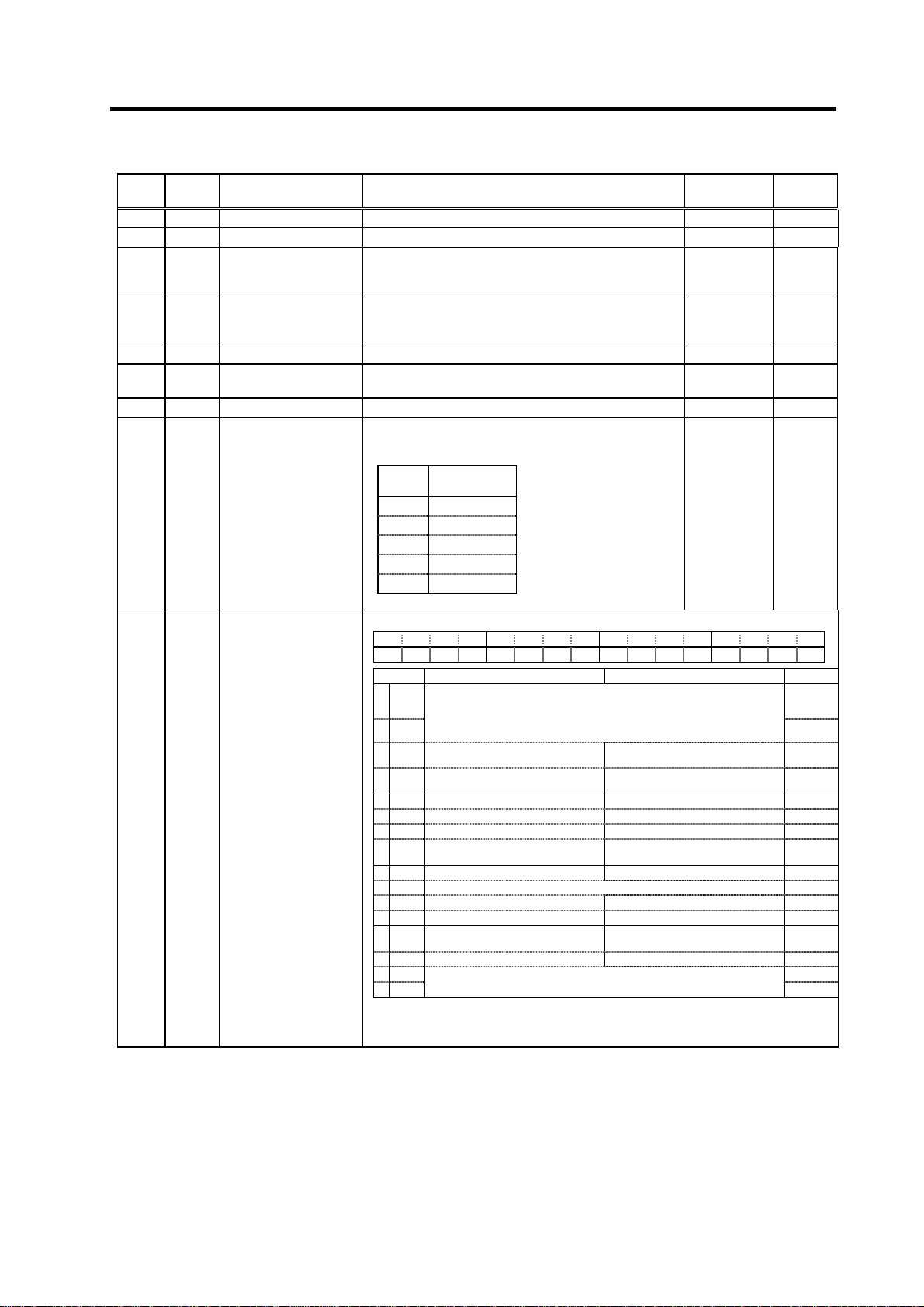
3. Setup
No. Abbr. Parameter name Details
SP089 Not used. Set "0". 0 0
SP090 Not used. Set "0". 0 0
SP091 OFSN*
Offset compensation
during motor PLG
Set the PLG offset for forward run.
Normally "0" is set.
forward run
SP092 OFSI*
Offset compensation
during motor PLG
Set the PLG offset for reverse run.
Normally "0" is set.
reverse run
SP093 Not used. Set "0". 0 0
SP094 LMAV Load meter output filter
Set the filter time constant of load meter output.
When "0" is set, a filter time constant is set to 226ms.
SP095 VFAV Fixed control constant Set by Mitsubishi. Set "0" unless designated in particular. 0 0
Set the gear ratio between the spindle side and the
detector side (except for the motor PLG) as indicated
below.
SP096 EGAR Encoder gear ratio
Setting
value
Gear ratio
(deceleration)
0 1 : 1
1 1 : 1/2
2 1 : 1/4
3 1 : 1/8
4 1 : 1/16
SP097 SPECO Orientation specification
F E D C B A 9 8 7 6 5 4 3 2 1 0
ostp orze ksft gchg zdir vg8x mdir fdir oscl pyfx dmin odi2 odi1
bit Meaning when set to 0 Meaning when set to 1 Standard
0 odi1 0
1 odi2
2dmin
3pyfx
4 oscl Indexing speed clamp invalid Indexing speed clamp valid 0
5 fdir Encoder installation polarity: + Encoder installation polarity: - 0
6 mdir Magnetic sensor polarity: + Magnetic sensor polarity: - 0
7vg8x
8 0
9 zdir This is used by Mitsubishi. Set to "0" unless particularly designated. 0
A 0
B 0
Cgchg
D ksft Orientation virtual target shift invalid Orientation virtual target shift valid 0
Eorze 0
Fostp
Orientation rotation direction
00: Previous (the direction in which the motor has so far rotated under
speed control)
10: Backward rotation
01: Forward rotation 11: Prohibited
Orientation completion advance
invalid
Excitation min. (50%) during
orientation servo lock invalid
Speed gain *1/8 during torque limit
valid
Gain changeover during orientation
invalid
This is used by Mitsubishi.
Set to "0" unless particularly designated.
Orientation completion advance
valid
Excitation min. (50%) during
orientation servo lock valid
Speed gain *1/8 during torque limit
invalid
Gain changeover during orientation
valid
(Note ) Set 0 if there is no particular explanation for the bit.
Parameters having an abbreviation with "*" (OFSN*, etc.) are validated right after the settings are changed by the personal
computer, without turning the spindle drive unit's power ON and OFF.
Setting range
(Unit)
-2048 to 2047
(-1mV)
-2048 to 2047
(-1mV)
0 to 32767
(3.5ms)
-3 to 4 0
Standard
setting
0
0
0
0
0
0
0
0
0
3 - 16
Page 77

3. Setup
No. Abbr. Parameter name Details
Speed loop gain
SP098 VGOP
SP099 VGOI
SP100 VGOD
SP101 DINP
SP102 OODR
SP103 FTM
SP104 TLOR
SP105 IQGO
SP106 IDGO
SP107 CSP2*
SP108 CSP3*
SP109 CSP4*
SP110 Not used. Set "0". 0 0
SP111 Not used. Set "0". 0 0
SP112 Not used. Set "0". 0 0
SP113 Not used. Set "0". 0 0
Parameters having an abbreviation with "*" (OSP2*, etc.) are validated right after the settings are changed by the personal
computer, without turning the spindle drive unit's power ON and OFF.
proportional term in
orientation control mode
Orientation control mode
speed loop gain integral
term
Orientation control mode
speed loop gain delay
advance term
Orientation advance
in-position width
Excessive error value in
orientation control mode
Index positioning
completion OFF time
timer
Torque limit value after
orientation completed l
Current loop gain
magnification 1 in
orientation control mode
Current loop gain
magnification 2 in
orientation control mode
Deceleration rate 2 in
orientation control mode
Deceleration rate 3 in
orientation control mode
Deceleration rate 4 in
orientation control mode
Set the speed loop proportional gain in orientation control
mode.
When the gain is increased, rigidity is improved in the
orientation stop but vibration and sound become larger.
Set the speed loop integral gain in orientation control
mode. 0 to 1000 60
Set a loop gain delay advance gain in orientation control
mode.
When this parameter is set to "0", PI control is applied.
When using the orientation completed advance function,
set the in-position width that is larger than the normal
in-position width defined in SP004 (OINP).
Set the excessive error detection width in orientation
control mode.
Set the time for forcedly turn OFF the index positioning
completion signal (different from the orientation
completion signal) after the leading edge of the indexing
start signal.
Set the torque limit value after orientation completed.
If the external torque limit signal is input, the torque limit
value set by this parameter is made invalid.
Set the magnification for current loop gain (torque
component) at orientation completion.
Set the magnification for current loop gain (excitation
component) at orientation completion.
Set the deceleration rate in orientation mode
corresponding to the gear 001.
When this parameter is set to "0", same as SP006 (CSP).
Set the deceleration rate in orientation mode
corresponding to the gear 010.
When this parameter is set to "0", same as SP006 (CSP).
Set the deceleration rate in orientation mode
corresponding to the gear 011.
When this parameter is set to "0", same as SP006 (CSP).
Setting range
(Unit)
0 to 1000 63
0 to 1000 15
1 to 2880
(1/16 deg)
0 to 32767
(1/4 pulse)
(1 pulse=
0.088 deg)
0 to 10000
(ms)
0 to 120 (%) 100
1 to 1000 (%) 100
1 to 1000 (%) 100
0 to 1000 0
0 to 1000 0
0 to 1000 0
Standard
setting
16
32767
200
3 - 17
Page 78

3. Setup
No. Abbr. Parameter name Details
An alarm "5C" will occur if the pulse miss value at the
orientation stop exceeds this setting value. (Note that this
SP114 OPER*
Orientation control
pulse miss check value
is invalid when set to "0".)
In this parameter, set the value to fulfill the following
conditions.
SP114 setting value > 1.5 × SP004
(orientation in-position width)
When the orientation clamp speed is changed by the
SP115 OSP2*
Orientation control
speed clamp value 2
control input, this parameter setting will be used instead of
SP005: OSP.
Indexing speed clamp valid
This parameter is used when (SP097: SPEC0/bit4 = 1).
SP116 OPYVR*
Minimum excitation value
after changeover (2nd
Set the minimum excitation rate when position control
input or external input is selected. 0 to 100 (%) 0
minimum excitation rate)
SP117 ORUT* Fixed control constant Set by Mitsubishi. Set "0" unless designated in particular. 0 0
Set the number of times to retry when an orientation or
SP118 ORCT*
Orientation control
number of retry times
feedback error occurs.
The warning (A9) is issued while retrying orientation, and
an alarm (5C) is issued when the set number of times is
exceeded.
Set the compensation magnification of the orientation
position loop gain for the H coil.
H coil orientation position loop gain
= SP001 (or SP002) × SP119/256
When set to "0", will become the same as SP001 or
SP119 MPGH*
Orientation control
position loop gain H coil
magnification
SP002.
Set the compensation magnification of the orientation
position loop gain for the L coil.
L coil orientation position loop gain
= SP001 (or SP002) × SP120/256
When set to "0", will become the same as SP001 or
SP120 MPGL*
Orientation control
position loop gain L coil
magnification
SP002.
Set the compensation magnification of the orientation
SP121 MPCSH*
Orientation deceleration
rate H coil magnification
deceleration rate for the H coil.
Orientation deceleration rate for the H coil
= SP006 × SP121/256
When set to "0", will become the same as SP006.
Set the compensation magnification of the orientation
SP122 MPCSL*
Orientation deceleration
rate L coil magnification
deceleration rate for the L coil.
Orientation deceleration rate for the L coil
= SP006 × SP122/256
When set to "0", will become the same as SP006.
This parameter is used for adjusting the operation during
SP123 MGD0*
Magnetic sensor output
peak value
magnetic sensor orientation. Set the peak value of the
magnetic sensor output. If the gap between the sensor
and magnet is small, set a large value. If the gap is large,
set a small value.
This parameter is used for adjusting the operation during
SP124 MGD1*
Magnetic sensor linear
zone width
magnetic sensor orientation. Set the width of the magnetic
sensor linear zone. If the installation radius of the magnet
is large, set a small value.
This parameter is used for adjusting the operation during
magnetic sensor orientation. Set the distance from the
SP125 MGD2*
Magnetic sensor
changeover point
target stop point for changing the position feedback to
magnetic sensor output.
Normally, a value that is approx. half of SP124 (MGDI) is
set.
SP126 Not used. Set "0". 0 0
SP127 Not used. Set "0". 0 0
SP128 Not used. Set "0". 0 0
Parameters having an abbreviation with "*" (OPER *, etc.) are validated right after the settings are changed by the personal
computer, without turning the spindle drive unit's power ON and OFF.
Setting range
(Unit)
0 to 32767
(360 deg/4096)
0 to 32767
(r/min)
0 to 100
(time)
0 to 2560
(1/256-fold)
0 to 2560
(1/256-fold)
0 to 2560
(1/256-fold)
0 to 2560
(1/256-fold)
1 to 10000
1 to 10000
1 to 10000
Standard
setting
0
0
0
0
0
0
0
Standard
magnet=542
Compact
magnet=500
Standard
magnet=768
Compact
magnet=440
Standard
magnet=384
Compact
magnet=220
3 - 18
Page 79

3. Setup
No. Abbr. Parameter name Details
Assign signals to general-input 1 (IN1: CN10-12 pin). Select the
signal to be assigned from the table below.
SP129 HI01
SP130 HI02
SP131 HI03
SP132 HI04
SP133 HI05
SP134 HI06
SP135 HI07
SP136 HI08
SP137 HI09
SP138 HI10
SP139 HI11
SP140 HI12
General-purpose input
selection 1
General-purpose input
selection 2
General-purpose input
selection 3
General-purpose input
selection 4
General-purpose input
selection 5
General-purpose input
selection 6
General-purpose input
selection 7
General-purpose input
selection 8
General-purpose input
selection 9
General-purpose input
selection 10
General-purpose input
selection 11
General-purpose input
selection 12
Setting
value
0 Not used for input 11 Speed selection 1
1 Orientation start 12
2 Indexing forward
3 Indexing reverse
4 Torque limit 1 15 Digital speed
5
6
7 Gear selection 1 18 L coil selection
8 Gear selection 2 19 Sub-motor
9 Alarm reset 20 Setting prohibited
10 Emergency stop 21 Load meter output
(Note1) Do not set "14" in any one of the parameters from
(Note2) Always set to "0" for any unused input among the
(Note3) Do not set any duplicated value in the parameters from
Assign signals to general-purpose input 2(IN2: CN10-3 pin).
The setting method is the same as SP129(HI01).
Assign signals to general-purpose input 3(IN3: CN10-13 pin).
The setting method is the same as SP129(HI01).
Assign signals to general-purpose input 4(IN4: CN10-4 pin).
The setting method is the same as SP129(HI01).
Assign signals to general-purpose input 5(IN5: CN10-14 pin).
The setting method is the same as SP129(HI01).
Assign signals to general-purpose input 6(IN6: CN10-5 pin).
The setting method is the same as SP129(HI01).
Assign signals to general-purpose input 7(IN7: CN10-15 pin).
The setting method is the same as SP129(HI01).
Assign signals to general-purpose input 8(IN8: CN10-6 pin).
The setting method is the same as SP129(HI01).
Assign signals to general-purpose input 9(IN9: CN10-16 pin).
The setting method is the same as SP129(HI01).
Assign signals to general-purpose input 10(IN10: CN10-8 pin).
The setting method is the same as SP129(HI01).
Assign signals to general-purpose input 11(IN11: CN10-18 pin).
The setting method is the same as SP129(HI01).
Assign signals to general-purpose input 12(IN12: CN10-9 pin).
The setting method is the same as SP129(HI01).
Meaning
run
run
Torque limit 2
Torque limit 3
SP129(H01) to SP140(H12).
parameters from SP129(H01) to SP140(H12).
SP129(H01) to SP140(H12) (excepting for "0").
Setting
value
13
14 Setting prohibited
16 Override input
17 S analog
Meaning
Speed selection 2
Speed selection 3
command valid
valid
high-speed
tapping
selection
changeover
Setting
0 to 21 0
0 to 19 0
0 to 19 0
0 to 19 0
0 to 19 0
0 to 19 0
0 to 19 0
0 to 19 0
0 to 19 0
0 to 19 0
0 to 19 0
0 to 19 0
range
Standard
3 - 19
Page 80

3. Setup
No. Abbr. Parameter name Details
Assign signals to general-purpose output (open emitter) 1
(OUT1: CN11-7 pin). Select the signal to be assigned from the
table below.
SP141 HO1e
SP142 HO2e
SP143 HO3e
SP144 HO4e
SP145 HO5e
SP146 HO6e
SP147 HO7e
SP148 HO8e
General-purpose
output selection
Open emitter 1
General-purpose
output selection
Open emitter 2
General-purpose
output selection
Open emitter 3
General-purpose
output selection
Open emitter 4
General-purpose
output selection
Open emitter 5
General-purpose
output selection
Open emitter 6
General-purpose
output selection
Open emitter 7
General-purpose
output selection
Open emitter 8
Setting
value
0 Not used for output 12 Current detection
1 Orientation
2 Positioning
3 Torque reach 15
4 In torque limit 16
5
6
7
8
9 In alarm 21 Alarm code output
10 In emergency stop 22 Alarm code output
11 In ready ON 23 Alarm code output
(Note 1) Do not set "5" or "6" in any one of the parameters from
(Note 2) Always set to "0" for any unused input among the
(Note 3) When handling the parameters from SP141(HO1e) to
(Note 4) When selecting the alarm code output, always set all of
Assign signals to general-purpose output (open emitter)
2(OUT2: CN11-17 pin).
The setting method is the same as SP141(HO1e).
Assign signals to general-purpose output (open emitter)
3(OUT3: CN11-8 pin).
The setting method is the same as SP141(HO1e).
Assign signals to general-purpose output (open emitter)
4(OUT4: CN11-18 pin).
The setting method is the same as SP141(HO1e).
Assign signals to general-purpose output (open emitter)
5(OUT5: CN11-9 pin).
The setting method is the same as SP141(HO1e).
Assign signals to general-purpose output (open emitter)
6(OUT6: CN11-10 pin).
The setting method is the same as SP141(HO1e).
Assign signals to general-purpose output (open emitter)
7(OUT7: CN11-20 pin).
The setting method is the same as SP141(HO1e).
Assign signals to general-purpose output (open emitter)
8(OUT8: CN9A-8 pin).
The setting method is the same as SP141(HO1e).
Meaning
complete
complete
Setting prohibited
Setting prohibited
Motor in forward
run
Motor in reverse
run
SP141(HO1e) to SP154(HO6c).
parameters from SP141(HO1e) to SP154(HO6c).
SP148(HO8c) in one group and the parameters from
SP149(HO1c) to SP154(HO6c) in another group, do
not set any duplicated value within the same group
(except for "0"). If groups are different, the same value
can be set.
the alarm code outputs (1 to 4) to any of the
parameters from SP141(HO1e) to SP154(HO6c).
Setting
value
13 Speed detection
14 Up-to-speed
17 In 1-drive unit
18 L coil selected
19 In sub-motor
20 Alarm code output
Meaning
Zero speed
Changing coil
2-motor
changeover
selection
1
2
3
4
Setting
range
Standard
0 to 23 0
0 to 23 0
0 to 23 0
0 to 23 0
0 to 23 0
0 to 23 0
0 to 23 0
0 to 23 0
3 - 20
Page 81

3. Setup
No. Abbr. Parameter name Details
SP149 HO1c
SP150 HO2c
SP151 HO3c
SP152 HO4c
SP153 HO5c
SP154
SP155 SAtyp
SP156 DGtyp
SP157 SAavr
SP158 Adofs*
SP159 ADcp1*
SP160 ADcp2*
SP161 Sgain*
Parameters having an abbreviation with "*" (Adofs*, etc.) are validated right after the settings are changed by the personal
computer, without turning the spindle drive unit's power ON and OFF.
General-purpose output
selection
Open collector 1
General-purpose output
selection
Open collector 2
General-purpose output
selection
Open collector 3
General-purpose output
selection
Open collector 4
General-purpose output
selection
Open collector 5
General-purpose output
selection
HO6c
Open collector 6
S analog speed
command input type
Digital speed command
input type
S analog speed
command input filter
S analog speed
command input offset
S analog speed
command input clamp 1
S analog speed
command input clamp 2
S analog speed
command input gain
Assign signals to general-purpose output (open collector)
1(OUT1c: CN12-7 pin).
The setting method is the same as SP141(HO1e).
Assign signals to general-purpose output (open collector)
2(OUT2c: CN12-17 pin).
The setting method is the same as SP141(HO1e).
Assign signals to general-purpose output (open collector)
3(OUT3c: CN12-8 pin).
The setting method is the same as SP141(HO1e).
Assign signals to general-purpose output (open collector)
4(OUT4c: CN12-18 pin).
The setting method is the same as SP141(HO1e).
Assign signals to general-purpose output (open collector)
5(OUT5c: CN12-9 pin).
The setting method is the same as SP141(HO1e).
Assign signals to general-purpose output (open collector)
6(OUT6c: CN10-20 pin).
The setting method is the same as SP141(HO1e).
Select where to input the S analog input.
[0]: Input between SE1(CN8A-7 pin) and SE2(CN8A-8 pin)
(Standard)
(Bipolar input: Possible to input 0 to ±10V)
[1]: Input between OR2(CN8A-17 pin) and SE1(CN8A-18
pin)
(Unipolar input: Possible to input 0 to +10V only)
Note that when "1" is set, the over writing function cannot
be used.
Set the digital speed command input method.
"0": Signed binary
"1": No sign 12-bit binary
"2": BCD2 digits
"3": BCD3 digits
Set the filter time constant of the S analog speed command
input. The actual time in respect to setting value is as
follows.
Filter time constant = 0.8ms × setting value
When "0" is set, this becomes 25.6ms.
Use the standard setting value if there is no problem.
Note that this setting is invalid during S analog high-speed
tapping.
Set the offset value of the S analog speed command input.
Set the value so that the spindle almost stops when the
input command is "0".
Note that the rotation of the spindle motor may not be
stopped in full with this setting.
This setting fluctuates depending on the usage time and
ambient temperature.
Set the + side non-sensitive band of the S analog speed
command input.
The speed command input is not accepted when the input
command is lower than the value set here. Thus, the motor
remains stopped
Set the - side non-sensitive band of the S analog speed
command input.
The detail is the same as SP159; only set in the minus side.
Set the gain of the S analog speed command input. Set so
that the motor runs at the highest speed when the
maximum speed command is input.
Setting
range
0 to 23 0
0 to 23 0
0 to 23 0
0 to 23 0
0 to 23 0
0 to 23 0
0 to 1
0 to 3 0
0 to 32767
(0.8ms)
-999 to 999
0 to 999 0
-999 to 0 0
0 to 2500
(1/
1000-fold)
Standard
SP155=0:
SP155=1:
SP155=0:
SP155=1:
0
0
When
0
When
262
When
1053
When
1147
3 - 21
Page 82

3. Setup
No. Abbr. Parameter name Details
SP162 SS00 Speed setting 0
SP163 SS01 Speed setting 1
SP164 SS02 Speed setting 2
SP165 SS03 Speed setting 3
SP166 SS04 Speed setting 4
SP167 SS05 Speed setting 5
SP168 SS06 Speed setting 6
SP169 SS07 Speed setting 7
SP170 SSchg
SP171 HSPT
SP172 VGHP
SP173 VGHI
SP174 HPYV
SP175 HSgn*
SP176 HADof*
Parameters having an abbreviation with "*" (HSgn*, etc.) are validated right after the settings are changed by the personal
computer, without turning the spindle drive unit's power ON and OFF.
Speed setting switch
filter
S analog high-speed
tapping motor maximum
speed
S analog high-speed
tapping speed loop
proportional gain
S analog high-speed
tapping speed loop
integral gain
S analog high-speed
tapping variable
excitation rate (min
value)
S analog high-speed
tapping speed
command gain
S analog high-speed
tapping speed
command offset
Regardless of whether the speed command mode is analog
or digital, the motor is run by the value set here when the
forward/reverse run signal is input.
Set the motor speed command value when the speed
selection 1 is assigned to the general-purpose input and the
input is turned ON.
Set the motor speed command value when the speed
selection 1,2 or 1,2,3 are assigned to the general-purpose
input and only the speed selection 2 is turned ON.
Set the motor speed command value when the speed
selection 1,2 or 1,2,3 are assigned to the general-purpose
input and the speed selection 1,2 are turned ON.
Set the motor speed command value when the speed
selection 1,2,3 are assigned to the general-purpose input
and the speed selection 3 is turned ON.
Set the motor speed command value when the speed
selection 1,2,3 are assigned to the general-purpose input
and the speed selection 1, 3 are turned ON.
Set the motor speed command value when the speed
selection 1,2,3 are assigned to the general-purpose input
and the speed selection 2, 3 are turned ON.
Set the motor speed command value when the speed
selection 1,2,3 are assigned to the general-purpose input
and the speed selection 1,2,3 are all turned ON.
Set the filter time constant when changing the speed
selection command input. The actual time in respect to the
setting value is as follows.
Filter time constant = 0.8ms × setting value
When "0" is set, this becomes no filter.
Use the standard setting value if there is no problem.
Set the maximum motor speed during S analog high-speed
tapping.
The value set in SP017(TSP) is applied when "0" is set.
During S analog high-speed tapping, when the gear noise
is louder than the regular speed loop operation or when the
tapping accuracy should be improved, set the motor
maximum tapping speed here.
Set the speed loop proportional gain during S analog
high-speed tapping. The higher the gain becomes, the
higher the response, but the greater the vibration and noise
become.
The value set in SP022(VGNP1) is applied when "0" is set.
Set the speed loop integral gain during S analog
high-speed tapping.
If the value of SP172(VGHP) is set, set the value so that the
setting value’s proportion between SP172 and SP173 is
1:1.
The value set in SP023(VGNI1) is applied when "0" is set.
Set the minimum value of the variable excitation rate during
S analog high-speed tapping.
Select a smaller value when gear noise is high. Select a
bigger value to improve tapping accuracy.
Set the speed command voltage gain during S analog
high-speed tapping.
The value set in SP161(Sgain) is applied when "0" is set.
Set the speed command voltage offset value during S
analog high-speed tapping.
The value set in SP158(ADofs) is applied when "0" is set.
Setting
range
0 to 32767
(r/min)
0 to 32767
(r/min)
0 to 32767
(r/min)
0 to 32767
(r/min)
0 to 32767
(r/min)
0 to 32767
(r/min)
0 to 32767
(r/min)
0 to 32767
(r/min)
0 to 32767
(0.8ms)
0 to 32767
(r/min)
0 to 1000 0
0 to 1000 0
0 to 100
(%)
0 to 2500
(1/1000-fold
-999 to 999 0
Standard
)
0
0
0
0
0
0
0
0
0
0
0
0
3 - 22
Page 83

)
3. Setup
No. Abbr. Parameter name Details
SP178 SMG*
SP179 LMG*
SP180 Sgnb* Fixed control constant
SP181 HSgnb* Fixed control constant
SP182 VGHD Fixed control constant
SP183 VCGH Fixed control constant
SP185 IQGH Fixed control constant
SP186 IDGH Fixed control constant
SP187 TQSLM Fixed control constant
SP188 TQgn* Fixed control constant
SP189 TQofs* Fixed control constant
SP190 TQflt* Fixed control constant
SP191 TQLMT* Fixed control constant
SP192 FNC0
SP193 LMG2*
Parameters having an abbreviation with "*" (MADJ*, etc.) are validated right after the settings are changed by the personal
computer, without turning the spindle drive unit's power ON and OFF.
Speed meter output full
scale adjustment
Load meter output full
scale adjustment
Function selection at
emergency stop
Load meter output
range changeover gain
Adjust the speed meter full scale.
Adjust so that the fluctuations of the speed meter is at the
intended position when "1" is set in SP177(MADJ).
Adjust the load meter full scale.
Adjust so that the fluctuations of the load meter is at the
intended position when "1" is set in SP177(MADJ).
Set by Mitsubishi.
Set "0" unless otherwise designated.
Set by Mitsubishi.
Set "0" unless otherwise designated.
Set by Mitsubishi.
Set "0" unless otherwise designated.
Set by Mitsubishi.
Set "0" unless otherwise designated.
Set by Mitsubishi.
Set "0" unless otherwise designated.
Set by Mitsubishi.
Set "0" unless otherwise designated.
Set by Mitsubishi.
Set "0" unless otherwise designated.
Set by Mitsubishi.
Set "0" unless otherwise designated.
Set by Mitsubishi.
Set "0" unless otherwise designated.
Set by Mitsubishi.
Set "0" unless otherwise designated.
Set by Mitsubishi.
Set "0" unless otherwise designated.
Set the state of alarm output and ready-ON output at the
emergency stop.
Setting
value
(Note) When the ready-ON input signal is turned OFF, the
ready-ON signal turns OFF regardless of the settings
above.
This will be validated when "21" (load meter output range
changeover) is set in SP129(HI01) to SP140(HI12) and the
signal is turned ON. The load meter output voltage gain
equals to the value set here, and not to the one in
SP179(LMG).
When "0" is set, the gain has the same value as set in the
usual SP179(LMG).
Alarm
output
0 Not
available
1 Available Same as above
2 Not
available
3 Available Continued ON
Ready-ON output
Turned OFF when the amount
of time set in SP055(SETM) has
passed after the motor had
stopped
Continued ON
Setting
range
0 to 1000
(1/1000-fold) 938
0 to 1000
(1/1000-fold) 938
0 to 2500 0
0 to 2500 0
0 to 1000 0
0 to 100 0
1 to 1000 0
1 to 1000 0
0 to 32767 60
-9999 to
9999
-999 to 999 0
0 to 2250 0
0 to 150 0
0 to 1000 15
0 to 32767
(1/1000-fold
Standard
15
0
3 - 23
Page 84

3. Setup
No. Abbr. Parameter name Details
Set the speed detection width when the speed excessive
Speed excessive
SP194 SE2R*
SP195 SE2T*
SP196
to
SP224
SP225 OXKPH*
SP226 OXKPL*
SP227 OXVKP*
SP228 OXVKI*
SP229 OXSFT*
SP230
to
SP241
SP242 Vavx* Fixed control constant Set by Mitsubishi. Set "0" unless designated in particular. 0 to 32767 0
SP243 UTTM* Fixed control constant Set by Mitsubishi. Set "0" unless designated in particular. 0 to 5000 0
SP244 OPLP* Fixed control constant Set by Mitsubishi. Set "0" unless designated in particular. 0 to 4096 0
SP245 PGHS* Fixed control constant Set by Mitsubishi. Set "0" unless designated in particular. 0 to 1 0
SP246 Not used. Set "0". 0 0
SP247 Not used. Set "0". 0 0
SP248 FNC Fixed control constant Set by Mitsubishi. Set "0" unless designated in particular. 0 to 7 0
SP249 SMO* Speed meter speed
SP250 LMO* Load meter voltage
SP251 Not used. Set "0". 0 0
SP252 Not used. Set "0". 0 0
Parameters having an abbreviation with "*" (SE2R*, etc.) are validated right after the settings are changed by the personal
computer, without turning the spindle drive unit's power ON and OFF.
deflection 2 detection
range
Speed excessive
deflection 2 detection
time
Not used. Set "0". 0 0
Position loop gain
magnification after
orientation completed
(H coil)
Position loop gain
magnification after
orientation completed
(L coil)
Speed loop proportional
gain magnification after
orientation completed
Speed loop cumulative
gain magnification after
orientation completed
Orientation virtual target
shift amount
Not used. Set "0". 0 0
deflection 2 alarm is output. The setting is as follows.
Detection width =
Speed command × current setting value/100 (r/min)
When the result of the expression above is smaller than
45r/min, the detection width is clamped at 45r/min. When
"0" is set, detection will not be carried out.
Set the duration required to detect the alarms indicated
above.
The speed excessive deflection 2 alarm is output when a
speed deflection larger than the speed detection width is
continued for more than the duration set here.
When "0" is set, detection will be carried out instantly.
If gain changeover is valid (SP097: SPEC0/bitC=1) during
orientation control, set the magnification of each gain
changed to after orientation completed.
Set the amount to shift the target position when orientation
virtual target position is valid (SP097: SPEC0/bitD=1).
Set the motor rotation speed when the speed meter 10V is
output.
When set to "0", this parameter becomes the same as
SP017 (TSP).
Set the voltage when the load meter 120% is output. When
set to "0", this becomes 10V.
Setting
range
(Unit)
0 to 100
(%)
0 to 3000
(ms)
0 to 2560
(1/256-fold)
0 to 2560
(1/256-fold)
0 to 2560
(1/256-fold)
0 to 2560
(1/256-fold)
0 to 2048
(360
deg/4096)
0 to 32767
(r/min)
0 to 10 (V) 0
Standard
setting
0
0
0
0
0
0
0
0
3 - 24
Page 85

3. Setup
No. Abbr. Parameter name Details
SP253 DA1NO*
SP254 DA2NO*
SP255 DA1MPY*
SP256 DA2MPY*
Parameters having an abbreviation with "*" (DA1NO *, etc.) are validated right after the settings are changed by the personal
computer, without turning the spindle drive unit's power ON and OFF.
D/A output channel 1
data number
D/A output channel 2
data number
DA output channel 1
magnification
DA output channel 2
magnification
Set the output data number for channel 1 of the D/A
output function.
When set to "0", the output is speedometer.
Set the output data number for channel 2 of the D/A
output function.
When set to "0", the output is speedometer.
Set the data magnification for channel 1 of the D/A output
function.
The output magnification is the setting value divided by
256.
When set to "0", the output magnification becomes 1-fold,
in the same manner as when "256" is set.
Set the data magnification for channel 2 of the D/A output
function.
The output magnification is the setting value divided by
256.
When set to "0", the output magnification becomes 1-fold,
in the same manner as when "256" is set.
Setting range
(Unit)
-32768 to
32767
-32768 to
32767
-32768 to
32767
(1/256-fold)
-32768 to
32767
(1/256-fold)
Standard
setting
0
0
0
0
No. Abbr. Parameter name Details
This parameter is valid only in the following two
conditional cases:
(a) In case that SP034 (SFNC2)/bit0=1
and SP034 (SFNC2)/bit2=0
Set the motor constants when using a special motor,
SP257
to
SP320
SP321
to
SP384
All motor constant parameters are validated with the spindle drive unit's power turned ON/OFF or with the alarm reset input turned
ON/OFF.
Motor constant
(H coil)
Motor constant
(L coil)
not described in the SP040 (MTYP) explanation and
when not using the coil changeover motor.
(b) In case that SP034 (SFNC2)/bit0=1
and SP034 (SFNC2)/bit2=1
Set the motor constant of the H coil of the coil
changeover motor.
(Note) It is not allowed for the user to change the setting.
(HEX setting)
This parameter is valid only in the following conditional
case:
(a) In case that SP034 (SFNC2)/bit0=1
and SP034 (SFNC2)/bit2=1
Set the motor constant of the L coil of the coil
changeover motor.
(Note) It is not allowed for the user to change the setting.
(HEX setting)
Setting range
(Unit)
0000 to FFFF 0000
0000 to FFFF 0000
Standard
setting
3 - 25
Page 86

p
3. Setup
3-3 Initial adjustment of the spindle PLG
3-3-1 Adjusting the PLG installation
The PLG (spindle motor speed detector) mounted on the
Mitsubishi framed spindle motor is shipped from Mitsubishi
in the adjusted state. If there are no particular problems,
carrying out the adjustment in this section is not required.
When dismantling a motor, or when using the built-in
spindle, the PLG detector is installed by the user, so the
PLG sensor's gap and output signal must be adjusted with
the following procedures. After installing and adjusting
these, carry out automatic adjustment of the PLG
according to each system.
Install the PLG and then adjust following the procedures on
the right. The output signal waveform can be retrieved from
the check terminal on the PCB. Measure the waveform with
an oscilloscope. The A/B phase output signal and the Z
phase pulse width can be adjusted with the volume (VR1 to
VR5) on the PCB. (The pulse width has been adjusted at
shipment, and normally does not need to be adjusted.)
(1) Checking the gap
Check that the gap between the sensor detection surface and detection gear circumference is
within 0.15±0.01mm as shown below. The gap is adjusted before shipment, but an error could
occur due to the effect of the dimensional difference of the notched fitting section provided for
installation, or the dimensional difference of the detection gears' outer diameter. If deviated from
the above range, adjust the gap following the section "(2) Adjusting the gap".
Sensor installation
seat
Sensor fixing screw
Marking line
Sensor section Gap with detection gear
(1) Checking the gap
(2) Adjusting the gap
(3) Checking the A and B phase output signal
(4) Adjusting the A and B phase output signal
(5) Checking the Z phase pulse width
(6) Adjusting the Z phase pulse width
(7) Checking the Z phase and A phase difference
(8) Adjusting the Z phase and A phase difference
Flow of PLG installation and adjustment
Sensor
Ga
0.15±0.01mm
Sensor detection
surface
Detection gear
Detection gear
circumference
3 - 26
Page 87
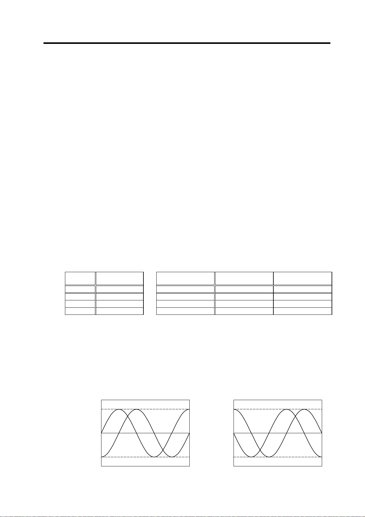
p
g
]
g
]
3. Setup
(2) Adjusting the gap
[1] Confirm that the detection gears are not rotating. The sensor could be damaged if the gap is
adjusted while the gears are rotating.
[2] Loosen the sensor fixing screw with the sensor fixed on the sensor installation seat.
[3] Using a clearance gauge, adjust so that the gap between the sensor detection surface and the
detection gears' circumference is 0.15±0.01mm.
[4] The sensor can be moved up and down or turned when the sensor fixing screw is loosened.
Position the rotating direction to match the marking line drawn on the sensor and installation
seat.
[5] When done adjusting the gap, apply a locking agent on the sensor fixing screw, and then fix
the sensor.
[6] After fixing the sensor, check the gap again. If operation is carried out with an excessively
small gap, the sensor and gears could contact, and the sensor could be damaged.
[7] Faults could occur if an excessive external force is applied or if the sensor detection surface is
damaged.
(3) Checking the A phase and B phase output signal
Check the output signal waveform by measuring the signals of the check terminals on the PCB
with the DC range of the synchroscope.
A phase output signal...... Across A-G
B phase output signal...... Across B-G
The PLG reference speed when confirming the output signal waveform differs according to the
number of output pulses. Refer to the following table for the reference speed for each number of
pulses. If operation is not possible at the reference speed, operate at a low speed within the range
in which the waveform can be confirmed.
Check terminal function
Check
terminal
A A phase 128 128 3600 r/min
B B phase 180 180 2500 r/min
Z Z phase 256 256 1800 r/min
G Ground 512 512 1200 r/min
Signal name
Reference speed for A and B phase output signal confirmation
Number of detection
gear teeth
The output signal waveform is confirmed when the motor is run in the forward direction and reverse
direction. The rotation directions are defined below.
During forward run . When the detection gears are rotating in the clockwise direction
looking from the sensor lead side.
During reverse run . When the detection gears are rotating in the counterclockwise
direction looking from the sensor lead side.
The normal A and B phase output signal waveform when running at the reference speed is shown
below. If the output signal waveform is not as shown below, refer to the next section "(4) Adjusting
the A and B phase output signal" and adjust.
Volta
e [V
1.45 ~ 1.55
A phase
B
hase
0
-1.45 ~ -1.55
A phase/B phase output signal waveform
during forward run
Time
Number of A and B
phase pulses
Volta
e[V
1.37 ~ 1.63
0
-1.37 ~ -1.63
A phase/B phase output signal waveform
during reverse run
Reference speed for
signal confirmation
A phaseB phase
Time
3 - 27
Page 88

V
p
p
β
3. Setup
(4) Adjusting the A phase and B phase output signal
[1] Set the drive unit in the open loop operation state. (Set the spindle parameter SP038/bitF to
"1" and turn the spindle drive unit power ON again.) There are cases when sudden speed
changes cannot be followed during open loop operation, so gradually change the speed
command.
[2] Forward run the motor and rotate the PLG at the reference speed.
[3] Using the PCB volume VR1 to VR4, adjust so that the A phase and B phase signals are within
the specified range. If the correct waveform cannot be attained even after adjusting with VR1
to VR4, adjust the gap again.
[4] Reverse run the motor and rotate the PLG at the reference speed.
[5] Adjust the output waveform by adjusting VR1 to VR4 in the same manner.
VR2
VR1
VR4
VR3
VR5
G
B
A
Z
PCB section
[6] Set the spindle drive unit to the closed loop operation state (normal operation).
[7] Run the motor at the maximum speed, and confirm that the A phase and B phase output
voltage peak value is larger than 0.8V on both the plus side and minus side during both
forward run and reverse run.
[8] Run the motor at the reference speed, and confirm that the A phase and B phase output signal
envelope is 0.4V or less.
The envelope is calculated by the expression below.
(Envelope) = (Maximum amplitude α) - (Minimum amplitude β)
[9] If the envelope is larger than the designated value, the deflection of the detection gears' outer
diameter may be large, so check the deflection.
Voltage [V]
0.8
A phase
hase
B
0
-0.8
Time
Example of A phase/B phase signal waveform
during forward run at maximum speed
Voltage [V]
olume function
Check
terminal
VR1 A phase offset adjustment
VR2 A phase gain adjustment
VR3 B phase offset adjustment
VR4 B phase gain adjustment
VR5
Z phase pulse width adjustment
(Already adjusted before shipment)
0
Definition of envelope
Signal name
Time
litude:
Maximum amplitude: α
Minimum am
3 - 28
Page 89

A
g
)
A
g
)
p
3. Setup
(5) Confirming the Z phase pulse width
Check the output signal waveform by measuring the signals of the check terminals on the PCB
with the DC range of the synchroscope.
A phase output signal...... Across A-G
Z phase output signal...... Across Z-G
The output signal waveform is confirmed during motor forward run and reverse run. Set the
synchroscope as follows to measure the waveform during each run direction.
During forward run .......... Apply a trigger at the rising edge of the Z phase output signal
During reverse run .......... Apply a trigger at the falling edge of the Z phase output signal
Confirm that the Z phase pulse width (time that the Z phase signal is at the "H" level = approx. 15V)
is 40% or more and 60% or less, when one cycle of the A phase signal is calculated as 100%. The
normal Z phase output signal waveform when run at the reference speed is shown below. If the
output signal waveform is not as shown below, refer to the next section "(6) Adjusting the Z phase
pulse width" and adjust.
The Z phase pulse width has been adjusted at shipment, with a combination of the sensor section
and PCB section having the same serial No. Thus, it normally does not need to be adjusted. If a
sensor section and PCB section having different serial numbers must be used, causing the Z
phase pulse width to deviate from the specified range, carry out the adjustment.
One A phase cycle = 100%
A phase
One A phase cycle = 100%
A phase
Q point
R point
0V
0V
hase
Z
Z phase pulse width: 40 to 60%
pply a trigger at the rising
edge of the Z phase
H level (reference
volta
e +15V
L level
Z phase
Z phase pulse width: 40 to 60%
pply a trigger at the falling
edge of the Z phase
H level (reference
volta
L level
A phase/Z phase output signal waveform
during forward run
A phase/Z phase output signal waveform
during reverse run
(6) Adjusting the Z phase pulse width
The Z phase pulse width can be adjusted with potentiometer VR5 on the PCB. VR5 is fixed after it
has been tested and adjusted to match the sensor section and PCB section having the same serial
No., so do not turn it unless a sensor section and PCB section with different serial numbers must
be used.
e +15V
3 - 29
Page 90

p
A
p
A
g
)
p
A
g
)
p
3. Setup
(7) Checking the Z phase and A phase difference
Check the output signal waveform by measuring the signals of the check terminals on the PCB
with the DC range of the synchroscope.
A phase output signal...... Across A-G
Z phase output signal...... Across Z-G
The output signal waveform is confirmed during motor forward run and reverse run. Set the
synchroscope as follows to measure the waveform during each run direction.
During forward run ..... Apply a trigger at the rising edge of the Z phase output signal
During reverse run ..... Apply a trigger at the falling edge of the Z phase output signal
The phase difference for the Z phase signal and A phase signal is defined as follows.
During forward run ..... Time difference between Z phase output signal rising edge and A
phase output signal zero point (Q point)
During reverse run ..... Time difference between Z phase output signal falling edge and A
phase output signal's 1/2 cycle point (R point)
Confirm that the phase difference between the Z phase to the A phase is within ±25% during both
forward and reverse run when one cycle of the A phase signal is calculated as100%. If the output
signal waveform is not as shown below, refer to the next section "(8) Adjusting the Z phase and A
phase difference" and adjust.
hase cycle = 100%
One A
One A phase cycle = 100%
A phase
Q
oint
0V
Tolerable
range of phase
difference
hase
Z
Phase difference of A phase and Z phase
Confirming the Z phase signal phase difference
pply a trigger at the rising
edge of the Z phase
H level (reference
volta
L level
during forward run
e +15V
0V
Z phase
Phase difference of
phase and Z phase
A phase
R
oint
Tolerable
range of phase
difference
Confirming the Z phase signal phase difference
during reverse run
pply a trigger at the falling
edge of the Z phase
H level (reference
volta
e +15V
L level
3 - 30
Page 91

3. Setup
(8) Adjusting the Z phase and A phase difference
[1] Stop the motor, and make sure that the detection gears are not rotating. The sensor could be
damaged if adjustments are carried out while the gears are rotating.
[2] Using a clearance gauge, adjust so that the gap between the sensor direction surface and the
detection gears’ circumference is 0.15±0.01mm, and loosen the sensor fixing screw.
[3] The phase difference of the Z phase to the A phase can be adjusted by rotating the sensor as
shown on the right. At this time, rotate the sensor a little bit while using the marking lines on
the sensor and installation seat as a guide.
[4] Tighten the sensor fixing screw so that the sensor
does not move, and confirm that the gap between the
sensor detection surface and detection gears'
circumference is 0.15 ± 0.01mm. Then, rotate the
gears and confirm the phase difference as explained
above.
[5] When the phase difference is within the tolerable
range, apply a locking agent on the sensor fixing
screw, and then fix the sensor. Check the gap again
after fixing the sensor.
Sensor
installation
seat
Marking
line
Rotate
2.1.1.1.1Adjustin
Sensor
fixing
screw
3 - 31
Page 92

4. Spindle Adjustment
4-1 D/A output specifications for spindle drive unit.................................................................................4-2
4-1-1 D/A output specifications ...........................................................................................................4-2
4-1-2 Setting the output data...............................................................................................................4-2
4-1-3 Setting the output magnification ................................................................................................4-3
4-2 Spindle control signal........................................................................................................................4-5
4-2-1 Spindle control input (NC to SP)................................................................................................ 4-5
4-2-2 Spindle control output (SP to NC)............................................................................................4-15
4-3 Adjustment procedures for each control......................................................................................... 4-27
4-3-1 Basic adjustments.................................................................................................................... 4-27
4-3-2 Adjusting the acceleration/deceleration operation................................................................... 4-30
4-3-3 Adjusting the orientation control ..............................................................................................4-39
4-3-4 Adjusting the multi-point indexing orientation control..............................................................4-55
4-3-5 Adjusting S-analog high-speed tapping control.......................................................................4-64
4-3-6 Adjusting coil changeover........................................................................................................4-69
4 - 1
Page 93

4. Spindle Adjustment
4-1 D/A output specifications for spindle drive unit
The spindle drive unit has a function to D/A output each control data. The spindle adjustment data
required to set the spindle parameters matching the machine can be D/A output. The data can be
measured with a hi-corder or oscilloscope, etc.
4-1-1 D/A output specifications
Item Explanation
No. of channels 2ch
Output cycle 444µs (min. value)
Output precision 8bit
Output voltage range
Output magnification
setting
Output pin
Function
0V to +5V (zero) to +10V,
0V to +10V for meter output
±1/256 to ±128-fold
CN9 connector
SMO = Pin 9 (D/A channel1)
LMO = Pin 19 (D/A channel2)
GND = Pin 1
Phase current feedback output function
IU (U phase current FB) : Pin 7
IV (V phase current FB) : Pin 17
4-1-2 Setting the output data
No. Abbr. Parameter name Explanation
SP253 DA1NO
SP254 DA2NO
No. Output data Original data unit
ch1: Speedometer output 10V=max. speed (Zero=0V) 0
0
ch2: Load meter output 10V=120% load (Zero=0V) 0 30-minute rating 12%/V 3.55ms
1 –
2 Current command Rated 100%=4096 8 30-minute rating 20%/V 3.55ms
3 Current feedback Rated 100%=4096 8 30-minute rating 20%/V 3.55ms
4 Speed feedback r/min 13 500rpm/V 3.55ms
80 Control input 1
81 Control input 2
82 Control input 3
83 Control input 4
84 Control output 1
85 Control output 2
86 Control output 3
87 Control output 4
D/A output channel 1 data No.
D/A output channel 2 data No.
Input the No. of the data to be output to each D/A output channel.
HEX Bit correspondence 3.55ms
CN9 connector
Pin
Name
GND
1
2
3
4
5
6
7
IU
8
SMO9
10
Output magnification
standard setting value
(SP255, SP256)
Pin
Name
11
12
13
14
15
16
17
IV
18
LMO 19
20
Output unit for
standard setting
Depends on maximum
speed
Output
cycle
3.55ms
4 - 2
Page 94

(
)
4. Spindle Adjustment
4-1-3 Setting the output magnification
(1) Meter output (Data No. 0)
With meter output, the output channel is fixed, and the output voltage range is 0 to 10V in the
positive range. Set the magnification with the following parameters. Also, low path filter can be set
on the load meter output.
No. Abbr. Parameter name Details
SP017 TSP* Maximum motor
SP094 LMAV* Load meter output
SP177
SP178 SMG*
SP179 LMG*
SP249 SMO Speedometer speed Set the motor rotation speed when the speedometer 10V is
SP250 LMO Load meter volta ge Set the voltage when the load meter 120% is output. When set
MADJ*
speed
filter
Meter full scale
compulsory output
Speed meter output
full scale adjustment
Load meter output
full scale adjustment
Set the maximum spindle motor speed.
When SP249=0, the motor speed will be the motor rotation
speed at the speedometer 10V output.
Set the filter time constant of load meter output.
When "0" is set, a filter time constant is set to 226ms.
When carrying out a full-scale adjustment to the speed meter
and load meter, set to "1" here so that the full scale voltage is
output and the adjustment mode is entered. Adjustment is
carried out with SP178(SMG) and SP179(LMG) at this time.
Always return the setting value to "0" when the adjustment is
completed.
Adjust the speed meter full scale.
Adjust so that the fluctuations of the speed meter is at the
intended position when "1" is set in SP177(MADJ).
Adjust the load meter full scale.
Adjust so that the fluctuations of the load meter is at the
intended position when "1" is set in SP177(MADJ).
output.
When set to "0", this parameter becomes the same as SP017
(TSP).
to "0", this becomes 10V.
(2) Internal data output (Data No. 1 to 13)
Normally, the standard setting value is set for the output magnification (SP255, SP256). When
"0" is set, the magnification will be the same as "256".
DATA ×
SP255
256
×
256
10 [V]
8 bit
+ 5 [V] (offset) = Output voltage [V]
(Example) To output current FB at a 30-minute stall rating 20%/V unit (SP253=3, SP255=8)
8
819.2 ×
No. Abbr. Parameter name Details
SP255 DA1MPY DA output channel 1
SP256 DA2MPY DA output channel 2
256
magnification
magnification
×
10
+ 5 = 6 [V]
256
Set the output magnification with a 1/256 unit.
When "0" is set, the magnification will be the same as "256".
Setting
range
1 to 32767
(r/min)
0 to 32767
(3.5ms)
0 to 1 0
0 to 1000
(1/1000-fold)
0 to 1000
(1/1000-fold)
0 to 32767
(r/min)
0 to 10
(V)
Setting
range
-32768 to
32767
(1/256-fold)
Standard
6000
0
938
938
0
0
Standard
0
0
4 - 3
Page 95

4. Spindle Adjustment
(3) Control signal output (Data No. 80 to 87)
A hexadecimal display is converted into a decimal and output. The method of calculating the
magnification is the same as (2). The status cannot be output for each bit, so output the status for
all 16 bits.
(Example) Orientation indexing control
With orientation indexing control, the following operations of the "Control output 4" can be
observed as shown on the right:
bit4: Orientation completed
bit7: Indexing positioning completed
Note that the weight of the D/A output differs for each bit.
10[V]
Motor speed
5
Control output 4
5[V]
0
Orientation indexing control sequence output
Orientation start
Orientation
complete
Orientation time
Orientation speed
Indexing
complete
Time
Indexing time
4 - 4
Page 96

4. Spindle Adjustment
4-2 Spindle control signal
The sequence input/output signals of the spindle drive unit are explained in this section. The status of
each signal is displayed on the spindle monitor of the personal computer when the personal computer
is connected.
4-2-1 Spindle control input (NC to SP)
(1) Spindle control input 1
Name Details
Spindle control input 1
bit0. READY ON command (RDY)
1) This signal is input when the motor is ready to rotate. This is valid when the circuit between 1 pin
(REDY) and 19 pin (CES1) of CN10 is closed (ON). When this signal is turned ON, the main
circuit of the converter unit will be turned ON.
2) Before this signal is turned ON or within approx. one second from when this signal is turned ON
till the "in READY ON" signal is turned ON, signals are not accepted even if turning the
forward/reverse run command, orientation command ON.
3) If this signal is turned OFF during motor rotation, the current to the motor is shut OFF and the
motor will coast to stop.
4) Turn this signal OFF for safety before the operator touches the spindle directly and
attaches/removes the workpiece or tools. However, be careful not to turn this signal ON/OFF
too frequently (100 times or more/day).
bit6. Parameter conversion command (PRM)
This is started when the spindle parameters are converted on the personal computer screen.
bit7. Drive unit alarm reset command (ALMR)
This turns ON while the alarm reset is input. Spindle alarms are reset.
However, if this signal is turned ON during the motor rotation, the power supplied to the motor is
shut off and the motor will coast to stop.
F E D C B A 9 8 7 6 5 4 3 2 1 0
TL3 TL2 TL1
bit Details
RDY
0
1
2
3
4
5
6
7
8
9
A
B
C
D
E
F
READY ON command
PRM
Parameter conversion command
ALMR
Drive unit alarm reset command
TL1
Torque limit 1
TL2
Torque limit 2
TL3
Torque limit 3
ALMR
PRM RDY
4 - 5
Page 97

4. Spindle Adjustment
Related spindle parameters
No. Abbr. Parameter name Details
SP129
to
SP140
HI01
to
HI12
General-purpose
input selection1
to
general-purpose
input selection12
Set the following value in any one of these parameters when
using the alarm reset.
“9”: Alarm reset
bit8. Torque limit 1 (TL1)
bit9. Torque limit 2 (TL2)
bitA. Torque limit 3 (TL3)
This signal is used to temporarily reduce the spindle motor's output torque such as when clamping
the spindle motor on the machine side. The torque limit is designated in percentage using the
motor's short-time rating as 100%.
Set the SP021, SP049 to SP054 torque limit value with a combination of TL1 to 3.
TL3 TL2 TL1 Torque limit value
0 0 1 SP021
0 1 0 SP049
0 1 1 SP050
1 0 0 SP051
1 0 1 SP052
1 1 0 SP053
1 1 1 SP054
Related spindle parameters
Setting
range
0 to 21 0
Standard
No. Abbr. Parameter name Details
SP021 TLM1* Torque limit 1 Set the torque limit rate when the torque limit signal 1 is
assigned to the general-purpose input and the input is turned
ON.
SP049 TLM2* Torque limit 2 Set the torque limit rate when the torque limit signal 1, 2 or 1, 2,
3 are assigned to the general-purpose input and only the torque
limit 2 is turned ON.
SP050 TLM3* Torque limit 3 Set the torque limit rate when the torque limit signal 1, 2 or 1, 2,
3 are assigned to the general-purpose input and the torque limit
1, 2 are turned ON.
SP051 TLM4* Torque limit 4 Set the torque limit rate when the torque limit signal 1, 2, 3 are
assigned to the general-purpose input and the torque limit 3 is
turned ON.
SP052 TLM5* Torque limit 5 Set the torque limit rate when the torque limit signal 1, 2, 3 are
assigned to the general-purpose input and the torque limit 1, 3
are turned ON.
SP053 TLM6* Torque limit 6 Set the torque limit rate when the torque limit signal 1, 2, 3 are
assigned to the general-purpose input and the torque limit 2, 3
are turned ON.
SP054 TLM7* Torque limit 7 Set the torque limit rate when the torque limit signal 1, 2, 3 are
assigned to the general-purpose input and the torque limit 1, 2,
3 are all turned ON.
SP129
to
SP140
HI01
to
HI12
General-purpose
input selection1
to
general-purpose
input selection12
Set the following value in any one of these parameters when
using the torque limit.
“4”: Torque limit signal1 (TL1)
“5”: Torque limit signal2 (TL2)
“6”: Torque limit signal3 (TL3)
Setting
range
0 to 120(%) 10
0 to 120(%) 20
0 to 120(%) 30
0 to 120(%) 40
0 to 120(%) 50
0 to 120(%) 60
0 to 120(%) 70
0 to 21 0
Standard
4 - 6
Page 98
4. Spindle Adjustment
(2) Spindle control input 2
Not used.
(3) Spindle control input 3
Name Details
Spindle control input 3
F E D C B A 9 8 7 6 5 4 3 2 1 0
bit Details
0
1
2
3
4
5
6
7
8
9
A
B
C
D
E MsI Sub-motor selection command (for 1-drive unit 2-motor changeover)
F
LCS ORC WRI WRN SRI SRN GR2 GR1 SC5 SC4 SC3 SC2 SC1
MsI
SC1
Spindle control mode selection command 1
SC2
Spindle control mode selection command 2
SC3
Spindle control mode selection command 3
SC4
Spindle control mode selection command 4
SC5
Spindle control mode selection command 5
GR1
Gear selection command 1
GR2
Gear selection command 2
SRN
Forward run start command
SRI
Reverse run start command
WRN
Indexing forward run command
WRI
Indexing reverse run command
ORC
Orientation start command
LCS
L coil selection command (When using coil changeover motor)
bit0. Spindle control mode selection command 1 (SC1)
bit1. Spindle control mode selection command 2 (SC2)
bit2. Spindle control mode selection command 3 (SC3)
bit3. Spindle control mode selection command 4 (SC4)
bit4. Spindle control mode selection command 5 (SC5)
SC5 SC4 SC3 SC2 SC1 Control mode
0 0 0 * *
0 0 1 * *
(Note) The asterisk indicates 1 or 0.
Since this input is automatically created inside, particular attention is not required.
Speed control
4 - 7
Page 99

bit5. Gear selection command 1 (GR1)
bit6. Gear selection command 2 (GR2)
This selects the number of spindle gear stages required to carry out orientation operation or
various position control operation.
GR2 GR1 Gear ratio
0 0 SP025, SP029
0 1 SP026, SP030
1 0 SP027, SP031
1 1 SP028, SP032
4. Spindle Adjustment
Related spindle parameters
No. Abbr. Parameter name Details
SP025 GRA1* Spindle gear teeth
SP026 GRA2* Spindle gear teeth
SP027 GRA3* Spindle gear teeth
SP028 GRA4* Spindle gear teeth
SP029 GRB1* Motor shaft gear
SP030 GRB2* Motor shaft gear
SP031 GRB3* Motor shaft gear
SP032 GRB4* Motor shaft gear
SP129
to
SP140
HI01
to
HI12
count 1
count 2
count 3
count 4
teeth count 1
teeth count 2
teeth count 3
teeth count 4
General-purpose
input selection1
to
general-purpose
input selection12
Set the number of gear teeth of the spindle corresponding to
gear 000.
Set the number of gear teeth of the spindle corresponding to
gear 001.
Set the number of gear teeth of the spindle corresponding to
gear 010.
Set the number of gear teeth of the spindle corresponding to
gear 011.
Set the number of gear teeth of the motor shaft corresponding
to gear 000.
Set the number of gear teeth of the motor shaft corresponding
to gear 001.
Set the number of gear teeth of the motor shaft corresponding
to gear 010.
Set the number of gear teeth of the motor shaft corresponding
to gear 011.
Set the following value in any of these parameters when using
the gear selection.
“7”: Gear selection1 (GR1)
“8”: Gear selection2 (GR2)
bit8. Forward run start command (SRN)
This is an operation command. The speed command must also be designated to rotate the motor.
If the orientation command is input, the orientation operation will have the priority.
This is validated when closing (ON) the circuit between 11 pin (SRN) and 19 pin (CES1) of CN10.
SRN Explanation
1 (ON)
0 (OFF)
The motor rotates in the counterclockwise direction (CCW) looking
from the shaft at the commanded speed.
The motor decelerates to a stop.
After stopping, the drive unit's power module turns OFF.
Setting
range
1 to 32767 1
1 to 32767 1
1 to 32767 1
1 to 32767 1
1 to 32767 1
1 to 32767 1
1 to 32767 1
1 to 32767 1
0 to 21 0
Spindle motor rotation direction
Counterclockwise
direction
Standard
setting
4 - 8
Page 100

4. Spindle Adjustment
bit9. Reverse run start command (SRI)
This is an operation command. The speed command must also be designated to rotate the motor.
If the orientation command is input, the orientation operation will have the priority.
This is validated when closing (ON) the circuit between 2 pin (SRI) and 19 pin (CES1) of CN1 0.
SRN Explanation
1 (ON)
0 (OFF)
(Note 1) If READY ON signal is turned OFF, both forward run and reverse run signals will not be accepted.
(Note 2) If both forward run signal and reverse run signal are turned ON, the motor will be stopped regardless of the value
The motor rotates in the clockwise direction (CW) looking from the
shaft at the commanded speed.
The motor decelerates to a stop.
After stopping, the drive unit's power module turns OFF.
of the speed command. In this case, note that the power is supplied to the motor even if the motor is stopped.
bitA. Indexing forward run command (WRN)
bitB. Indexing reverse run command (WRI)
This is valid when the orientation start command is ON.
WRI WRN Explanation
1
(ON)
0
(OFF)
1
(ON)
0
(OFF)
For the related parameters, refer to the adjustment for the indexing control in the adjustment procedure for each control.
1
(ON)
1
(ON)
0
(OFF)
0
(OFF)
Setting prohibited.
Indexing is carried out in the counterclockwise (CCW)
direction looking from the motor end.
Indexing is carried out in the clockwise (CW) direction
looking from the motor end.
Indexing is not carried out.
bitC. Orientation start command (ORC)
This signal is used to start orientation. Orientation has a priority when the orientation start
command is input.
ORC Explanation
1 (ON) Orientation starts regardless of the run command (SRN, SRI).
0 (OFF)
For the related parameters, refer to the adjustment for the orientation control in the adjustment procedure for each control.
When a run command (SRN, SRI) is selected, the rotation starts again
at the commanded speed.
bitD. L coil selection command (LCS)
This command is input to select the coil method for changing the coil. Note that coil changeover is
not possible when orientation is commanded. The coil is fixed when the orientation command is
input.
LCS Explanation
1 (ON) The low-speed command is selected.
0 (OFF) The high-speed command is selected.
bitE. Sub-motor selection command (Msl)
This command input signal is used to select sub-motor when changing over 1-drive unit 2-motor
(spindle motor/general purpose motor).
MS Explanation
1
Sub-motor is selected.
(ON)
0
Main-motor is selected.
(OFF)
Spindle motor rotation direction
Clockwise direction
4 - 9
 Loading...