

Page 1
USA-E99981-151-C
Page 2

Page 3

Introduction
Thank you for selecting the Mitsubishi numerical control unit.
This instruction manual describes the handling and caution points for using this AC
servo/spindle.
Incorrect handling may lead to unforeseen accidents, so always read this instruction
manual thoroughly to ensure correct usage.
Make sure that this instruction manual is delivered to the end user.
Always store this man ual in a safe place.
All specifications for the MDS-C1 Series are described in this manual. However, each
CNC may not be provided with all specifications, so refer to the specifications for the
CNC on hand before starting use.
Notes on Reading This Man ual
(1) Since the description of this specification manual deals with NC in general, for the
specifications of individual machine tools, refer to the manuals issued by the
respective machine manufacturers. The "restrictions" and "available functions"
described in the manuals issued by the machine manufacturers have precedence
to those in th is manual.
(2) This manual describes as many special operations as possible, but it should be
kept in mind that items not mentioned in this manual cannot be performed.
i
Page 4
Please read this manual and auxiliary documents before starting installation, operation,
maintenance or inspection to ensure correct usage. Thoroughly understand the device, safety
information and precautions before starting operation.
The safety precautions in this instruction manual are ranked as "WARNING" and "CAUTION".
Note that some items described as
the situation. In any case, important information that must be observed is described.
The numeric control unit is configured of the control unit, operation board, servo drive unit,
spindle drive unit, power supply + servo drive or spindle drive, servomotor, and spindle motor,
etc.
In this manual, the following items are generically called the "servomotor".
• Servomotor
• Spindle motor
DANGER
WARNING
CAUTION
Precautions for safety
When there is a potential risk of fatal or serious injuries if
handling is mistaken.
When fatal or serious injuries may occur if handling is
mistaken.
When a dangerous situation may occur if handling is mistaken
leading to medium or minor injuries, or physical damage.
CAUTION
may lead to major results depending on
In this manual, the following items are generically called the "servo drive unit".
• Servo drive unit
• Spindle drive unit
• Power supply + servo drive or spindle drive
ii
Page 5
There are no "DANGER" items in this manual.
1. Electric shock prevention
Do not open the front cover while the power is ON or during operation. Failure to observe this
could lead to electric shocks.
Do not operate the unit with the front cover removed. The high voltage terminals and charged
sections will be exposed, and can cause electric shocks.
Do not remove the front cover even when the power is OFF unless carrying out wiring work or
periodic inspections. The inside of the servo drive unit is charged, and can cause electric
shocks.
Wait at least 15 minutes after turning the power OFF before starting wiring, maintenance, or
inspections. Failure to observe this could lead to electric shocks.
Ground the servo drive unit and servomotor with Class C (former class 3) grounding or higher.
Wiring, maintenance, and inspection work must be done by a qualified technician.
Wire the servo drive unit and servomotor after installation. Failure to observe this could lead to
electric shocks.
Do not touch the switches with wet hands. Failure to observe this could lead to electric shocks.
Do not damage, apply forcible stress, place heavy items on the cables or get them caught.
Failure to observe this could lead to electric shocks.
DANGER
WARNING
1. Fire prevention
Install the servo drive unit, servomotor and regenerative resistor on noncombustible material.
Direct installation on combustible material or near combustible materials could lead to fires.
Shut off the power on the servo drive unit side if a fault occurs in the servo drive unit. Fires
could be caused if a large current continues to flow.
Provide a sequence that shut off the power at the regenerative resister error signal-ON when
using the regenerative resistor. The regenerative resistor could abnormally overheat and cause
a fire due to a fault in the regenerative transistor, etc.
CAUTION
iii
Page 6
CAUTION
2. Injury prevention
Do not apply a voltage other than that specified in Instruction Manual on each terminal. Failure
to observe this item could lead to ruptures or damage, etc.
Do not mistake the terminal connections. Failure to observe this item could lead to ruptures or
damage, etc.
Do not mistake the polarity ( , ). Failure to observe this item could lead to ruptures or
damage, etc.
Do not touch the fin on the servo drive unit, regenerative resister or servomotor, etc., while the
power is turned ON or immediately after turning the power OFF. These parts may reach high
temperatures, and can cause burns.
3. Various precautions
Observe the following precautions. Incorrect handling of the unit could lead to faults, injuries and
electric shocks, etc.
(1) Transportation and installation
Correctly transport the product according to its weight.
Use the servomotor's hanging bolts only when transporting the servomotor. Do not transport
the servomotor when it is installed on the machine.
Do not stack the products above the tolerable number.
Do not hold the cables, axis or detector when transporting the servomotor.
Do not hold the connected wires or cables when transporting the servo drive unit.
Do not hold the front cover when transporting the servo drive unit. The unit could drop.
Follow this Instruction Manual and install the unit in a place where the weight can be borne.
Do not get on top of or place heavy objects on the unit.
Always observe the installation directions.
Secure the specified distance between the servo drive unit and control panel, or between the
servo drive unit and other devices.
Do not install or run a servo drive unit or servomotor that is damaged or missing parts.
Do not block the intake or exhaust ports of the servomotor provided with a cooling fan.
Do not let foreign objects enter the servo drive unit or servomotor. In particular, if conductive
objects such as screws or metal chips, etc., or combustible materials such as oil enter,
rupture or breakage could occur.
The servo drive unit and servomotor are precision devices, so do not drop them or apply strong
impacts to them.
iv
Page 7
CAUTION
Store and use the units under the following environment conditions.
Environment
Ambient temperature
Ambient humidity
Storage temperature
Storage humidity
Atmosphere
Altitude 1000m or less above sea level
Vibration To follow separate specifications
Securely fix the servomotor to the machine. Insufficient fixing could lead to the servomotor
slipping off during operation.
Always install the servomotor with reduction gear in the designated direction. Failure to do
so could lead to oil leaks.
Never touch the rotary sections of the servomotor during operations. Install a cover, etc.,
on the shaft.
When installing a coupling to a servomotor shaft end, do not apply an impact by
hammering, etc. The detector could be damaged.
Do not apply a load exceeding the tolerabl e load onto the servomotor shaft. The shaft
could break.
When storing for a long time, please contact the Service Center or Service Station.
To follow separate specifications
To follow separate specifications –15°C to +70°C
To follow separate specifications
Servo drive unit Servomotor
0°C to +55°C
(with no freezing)
Indoors (Where unit is not subject to direct sunlight)
With no corrosive gas, combustible gas, oil mist or dust
Conditions
0°C to +40°C
(with no fre ezing)
80%RH or less
(with no dew condensation)
90% RH or less
(with no dew condensation)
v
Page 8
(2) Wiring
(3) Trial operation and adjustment
Correctly and securely perform the wiring. Failure to do so could lead to runaway of the
servomotor.
Do not install a condensing capacitor, surge absorber or radio noise filter on the output side of
the servo drive unit.
Correctly connect the output side (terminals U, V, W). Failure to do so could lead to abnormal
operation of the servomotor.
Do not directly connect a commercial power supply to the servomotor. Doing so could lead to
faults.
When using an inductive load such as a relay, always connect a diode as a noise measure
parallel to the load.
When using a capacitance load such as a lamp, always connect a protective resistor as a noise
measure serial to the load.
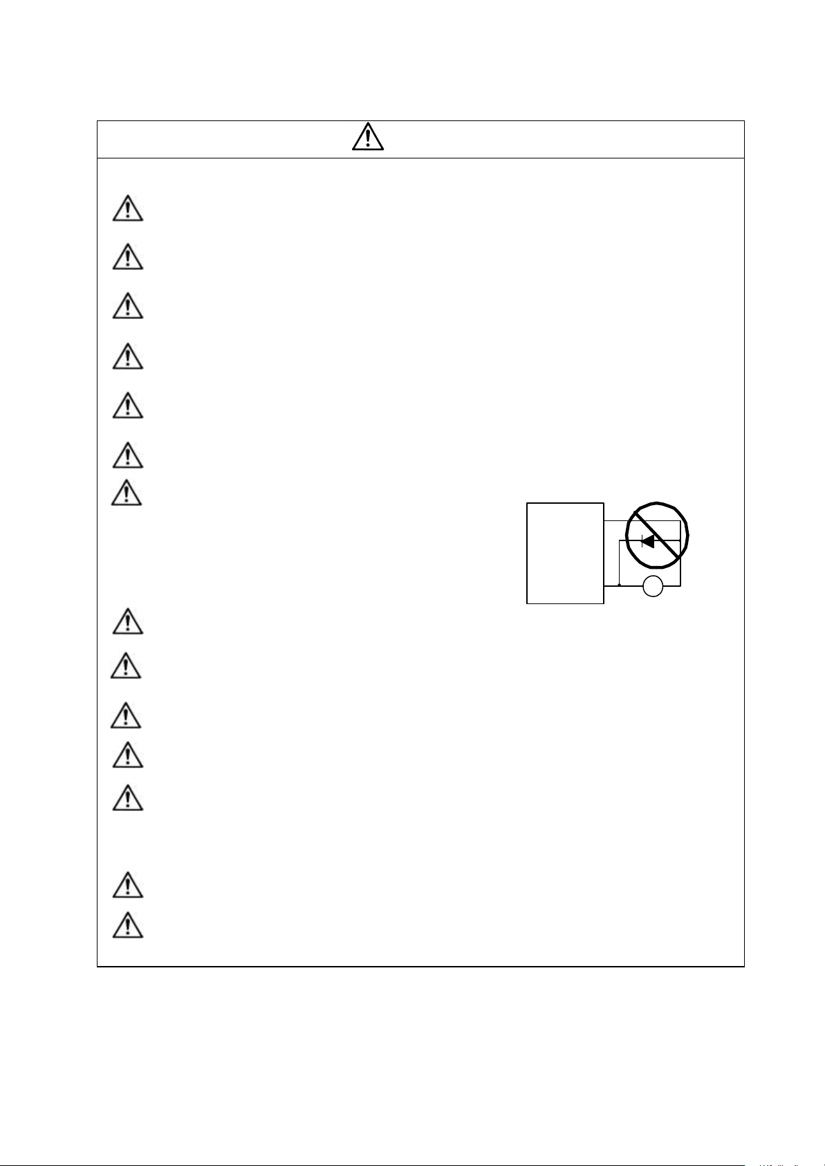
Do not reverse the direction of a diode which
connect to a DC relay for the control output
signals to suppress a surge.
Connecting it backwards could cause the drive
unit to malfunction so that signals are not output,
and emergency stop and other safety circuits are
inoperable.
Do not connect/disconnect the cables connected between the units while the power is ON.
Securely tighten the cable connector fixing screw or fixing mechanism. An insecure fixing could
cause the cable to fall off while the power is ON.
When us ing a shielded cable instructed in the connection manual, always ground the cable with
a cable clamp, etc.
Always separate the signals wires from the power supply line and power line.
Use wires and cables that have a wire diameter, heat resistance and flexibility that conforms to
the system.
CAUTION
Serv o drive unit
COM
(24VDC)
Control output
sig nal
RA
Check and adjust each program and parameter before starting operation. Failure to do so could
lead to unforeseen operation of the machine.
Do not make remarkable adjustments and changes as the operation could become unstable.
vi
Page 9
CAUTION
(4) Usage methods
Install an external emergency stop circuit so that the operation can be stopped and power
shut off immediately.
Turn the power OFF immediately if smoke, abnormal noise or odors are generated from the
servomotor or servo drive unit.
Unqualified persons must not disassemble or repair the unit.
Never make modifications.
Reduce magnetic damage by installing a noise filter, etc . The electronic devices used near the
servo drive unit could be affected by magnetic noise.
Use the servomotor, servo drive unit and regenerative resistor with the designated combination.
Failure to do so could lead to fires or trouble.
The brake (magnetic brake) assembled into the servomotor are for holding, and must not be
used for normal braking.
There may be cases when holding is not possible due to the magnetic brake's life or the
machine construction (when ball screw and servomotor are coupled via a timing belt, etc.).
Install a stop device to ensure safety on the machine side.
After changing the programs/parameters or after maintenance and inspection, always test the
operation before starting actual operation.
Do not enter the movable range of the machine during automatic operation. Never place body
parts near or touch the spindle during rotation.
Follow the power supply specification conditions given in the separate specifications manual for
the power (input voltage, input frequency, tolerable sudden power failure time, etc.).
In the following explanations on bits, set all bits not used, including blank bits, to "0".
When the breaker is shared for multiple power supply units, if a short -circuit fault occurs in the
unit with the smallest capacity, the breaker may not function. This is dangerous, so do not share
the breaker.
Please do not use a dynamic brake as a usual slowdown stop. When continuation operation is
carried out, the brake resistance for dynamic may be damaged.
(5) Troubleshooting
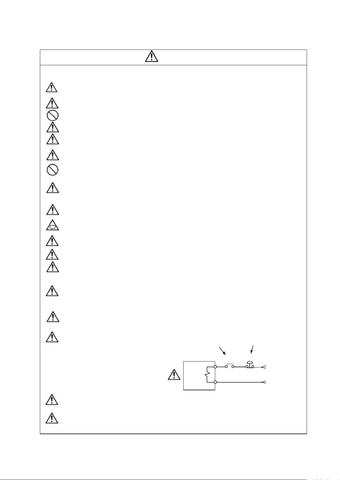
If a hazardous situation is predicted during power failure or product trouble, use a servomotor
with magnetic brakes or install an external brake mechanism.
Use a double circuit configuration
that allows the operation circuit for
the magnetic brakes to be operated
even by the external emergency
stop signal.
Always turn the input power OFF when an alarm occurs.
Never go near the machine after restoring the power after a power failure, as the machine
could start suddenly. (Design the machine so that personal safety can be ensured even if the
machine starts suddenly.)
Shut off with the servomotor
brak e control output.
Servomotor
Magnetic
!
brake
vii
Shut off with NC brake
control PLC output.
MBR
EMG
24VDC
Page 10
CAUTION
(6) Maintenance, inspection and part replacement
Always backup the servo drive unit programs and parameters before starting maintenance or
inspections.
The capacity of the electrolytic capacitor will drop due to deterioration. To prevent secondary
damage due to failures, replacing this part every five years when used under a normal
environment is recommended. Contact the Service Center or Service Station for
replacement.
Do not perform a megger test (insulation resistance measurement) during inspections.
If the battery low warning is issued, back up the machining programs, tool data and
parameters with an input/output unit, and then replace the battery.
Do not short circuit, charge, overheat, incinerate or disassemble the battery.
(7) Disposal
Treat this unit as general industrial waste.
If the heat radiating fins are protruding on the back face of the MDS Series, substitute Freon
is used. Do not dispose of this type of unit as general industrial waste. Always contact the
Service Station or Service Center for disposal.
Do not disassemble the servomotor or servo drive unit.
Dispose of the battery according to local laws.
(8) General precautions
The drawings given in this Specifications and Maintenance Instruction Manual show the covers and
safety partitions, etc., remove d to provide a clearer explanation. Always return the covers or partitions to
their respective places before starting operation, and always follow the instructions given in this manual.
viii
Page 11
Compliance to European EC Directives
1. European EC Directives
In the EU Community, the attachment of a CE mark (CE marking) is mandatory to indicate that the
basic safety conditions of the Machine Directives (issued Jan. 1995), EMC Directives (issued Jan.
1996) and the Low-voltage Directives (issued Jan. 1997) are satisfied. The machines and devices in
which the servo and spindle drive are assembled are the targets for CE marking.
(1) Compliance to EMC Directives
The servo and spindle drive are components designed to be used in combination with a machine
or device. These are not directly targeted by the Directives, but a CE mark must be attached to
machines and devices in which these components are assembled. "Appendix 2", which explains
the unit installation and control panel manufacturing method, etc., has been prepared to make
compliance to the EMC Directives easier.
(2) Compliance to Low -voltage Directives
The MDS-C1 Series units are targeted for the Low-voltage Directives. An excerpt of the
precautions given in this specification is given below. Please read this section thoroughly before
starting use.
A Self-Declaration Document has been prepared for the EMC Directives and Low-voltage
Directives. Contact Mitsubishi or your dealer when required.
2. Cautions for EC Directive compliance
Use the Lo w-voltage Directive compatible parts for the servo/spindle drive and servo/spindle motor. In
addition to the items described in this instruction manual, observe the items described below.
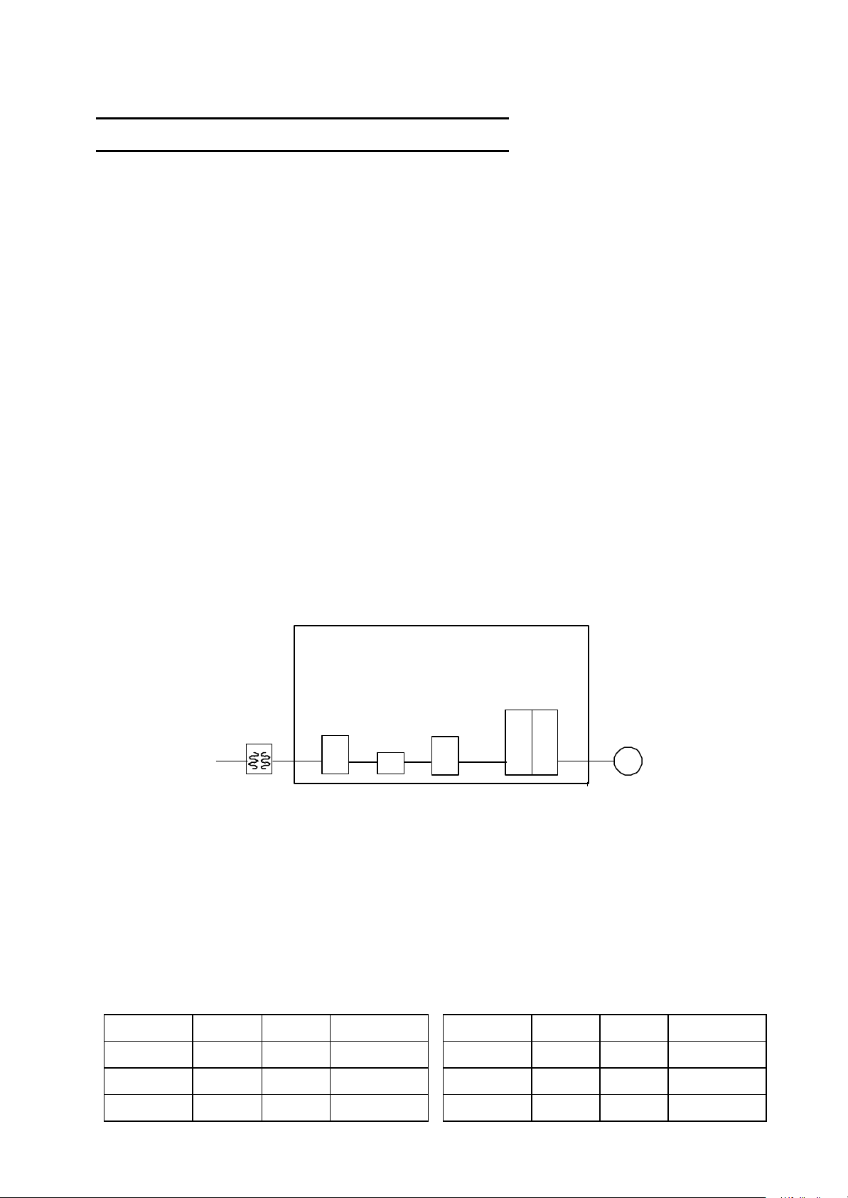
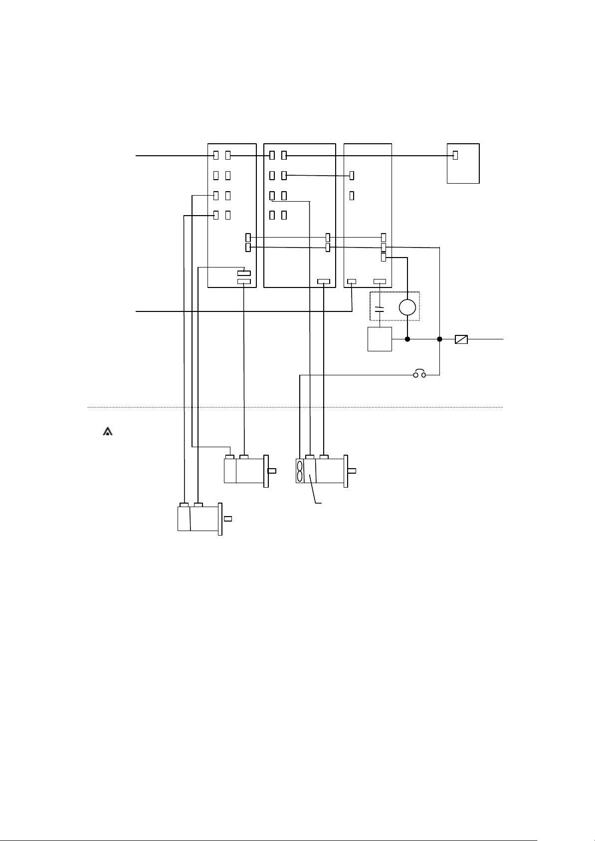
(1) Configuration
Control panel
Servo/spindle drive
Isolating
transformer
Circuit breaker
CB MC M
Electromagnetic
contactor
AC reactor
Motor
Use a type B breaker
(Note) Type A ... AC and pulse detection possible
Type B ... Both AC and DC detection possible
(2) Environment
Use the units within an Overvoltage Protection Category III and Pollution Class of 2 or less
environment as stipulated in IEC60664.
(a) To attain the Overvoltage Category II, insert an EN or IEC Standard compliant star-connection
insulated transformer in the power supply unit input.
(b) To attain a Pollution Class of 2, install the servo/spindle drive unit in a control panel having a
structure (IP54 or higher) in which water, oil, carbon or dust cannot enter.
Drive unit Motor
Ambient
temperature
Humidity
Altitude
During
operation
0°C to 55°C
90%RH or
less
1000m or
less
Storage
–15°C to
70°C
90%RH or
less
1000m or
less
During
transportation
–15°C to 70°C
90%RH or less
10000m or less
Ambient
temperature
Humidity
Altitude
During
operation
0°C to 40°C
80%RH or
less
1000m or
less
Storage
–15°C to
70°C
90%RH or
less
1000m or
less
During
transportation
–15°C to 70°C
90%RH or less
10000m or less
ix
Page 12
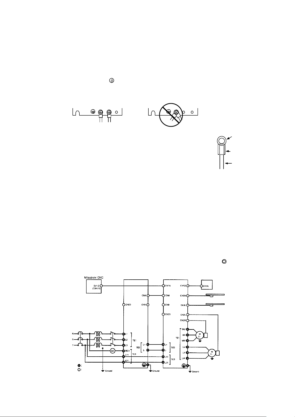
PE terminal
PE terminal
Crimp terminal
Insulation tube
Wire
(3) Power supply
(a) Use the servo/spindle drive unit under the Overvoltage Category III conditions stipulated in
IEC60664.
(b) Do not omit the circuit breaker and electromagnetic contactor.
(4) Installation
(a) To prevent electric shocks, always connect the servo/spindle drive unit protective earth (PE)
terminal (terminal with mark) to the protective earth (PE) on the control panel. (Always
ground even when using an earth leakage breaker.)
(b) When connecting the earthing wire to the protective earth (PE) terminal, do not tighten the wire
terminals together. Always connect one wire to one terminal.
(5) Wiring
(a) Always use crimp terminals with insulation tubes so that the wires
connected to the drive unit terminal block do not contact the
neighboring terminals.
(b) Use a tin-plated crimp terminal that does not contain zinc for
connecting the earthing wire. When tightening the screw, take care
not to crush the screw threads.
(c) Refer to EN60204-1 when selecting the wire size. (Refer to section
"8.5 Selection of wire size" for details.)
– Ambient temperature: 40°C max.
– Wire sheath: Cable installed on walls without ducts or conduits
– The control panel and duct wiring must be 3m or less.
If the conditions differ, refer to Table 5 in EN60204-1 Appendix C.
(6) Peripheral devices and options
(a) Use EN/IEC Standards compliant parts for the circuit breaker and electromagnetic contactor.
(7) Miscellaneous
(a) Refer to "Appendix 2 EMC INSTALLATION GUIDELINES" for methods on complying with the
EMC Directives.
(b) When using in Europe, earth the device according to each country's requirements.
(c) The control circuit connector (¡) is safety separated from the main circuit (
).
Circuit breaker
Main circuit
Control circuit
External emergency
stop input
AC reactor
B-AL[ ] [ ] K
Electromagnetic
contactor
MDS-CH-CV-[ ] MDS-CH-V2-[ ]
External brake
output contact
BT-[ ]
Motor end
detector
Motor end
detector
x
Page 13

Instruction Manual for Compliance with UL/c-UL Standard
The instruction of UL/c-UL listed products is described in this manual.
The descriptions of this manual are conditions to meet the UL/c-UL standard for the UL/c-UL listed
products. To obtain the best performance, be sure to read this manual carefully before use.
To ensure proper use, be sure to read specification manual, connection manual and maintenance manual
carefully for each product before use.
1. UL/c-UL listed products
[CNC system]
Unit name Unit part number
NC control unit FCU6-MU [*1]-[*2], FCU6-MA [*1]-[*2]
Display unit
Keyboard unit
Base I/O unit FCU6-DX [*3], HR377, HR378, HR353
Remote I/O unit FCUA-DX [*4]
I/O module HR357, HR371, QY231
[AC servo/spindle system]
Unit name Unit part number
Power supply unit MDS-B-CVE- [*5], MDS-C1-CV-[*5]
Servo drive unit
Spindle drive unit MDS-B-SP [*38] -[*9], MDS-C1-SP [*38]-[*9]
Option unit MDS-B-PJEX
Battery unit FCU6-BT4D1
Servo motor
Spindle Motor
FCU6-DU [*39][*40], FCU6-YZ [*39][*40] , FCUA-LD [*41], FCUA-CT [*41], FCUA-CR [*41],
FCU6-YZ [*39][*40], FCU6-TZ [*39][*40], FCU6-KB0 [*42], FCUA -KB [*42]
MDS-B-V1- [*6], MDS-B-V14- [*6], MDS-C1-V1- [*6], MDS-B-V2- [*7], MDS-B-V24- [*7],
MDS-C1-V2- [*7] , MDS-B-SVJ2- [*8]
HA-FF [*10][*11][*12][*13][*14][*15][*16][*17][*18][*19]
HC-MF [*10][*11][*12][*13][*14][*15][*16][*17][*18][*19]
HC-SF [*10][*11][*12][*13][*14][*15][*16][*17][*18][*19]
HC-RF [*10][*11][*12][*13][*14][*15][*16][*17][*18][*19]
HC-MF [*10][*11][*12][*13][*14][*15][*16][*17][*18][*19]
HC-RF [*10][*11][*12][*13][*14][*15][*16][*17][*18][*19]
HC [*20][*11][*21][*14][*22] -[*23][*24]
SJ [*25][*26][*27] -[*28][*29][*30][*31]-[*32]
SJ [*33][*26][*28][*34][*35][*36][*37][*31]
Suffixes listed below may be attached to the above part numbers at portions marked with [*]. For details
regarding specifications, see the specification manuals.
[*1] 011, 013, 021, 031, 032, 515, 516, 517, 535, 536
[*2] 12, 23
[*3] 210, 211, 220, 221, 310, 311, 320, 321, 330, 331, 340, 341, 350, 351, 410, 411, 420, 421, 430, 431, 440,
441, 450, 451
[*4] 100, 101, 110, 111, 120, 121, 130, 131, 140, 141
[*5] 37, 55, 75, 110, 150, 185, 220, 260, 300, 370, (450, 550: Only B)
[*6] 01, 03, 05, 10, 20, 35, 45S, 45, 70, 90, 110, 150
[*7] 0101, 0301, 0303, 0501, 0503, 0505, 1003, 1005, 1010, 2010, 2020, 3510S, 3510, 3520S, 3520, 3535, 4520,
4535, 4545, 7035, 7045, 7070S, 7070
[*8] 01, 03, 04, 06, 07, 10, 20
[*9] 04, 075, 15, 22, 37, 55, 75, 110, 150, 185, 220, 260, 300, 370, (450,550:Only MDS-B Series)
[*10] 05, 1, 2, 3, 4, 5, 6, 7, 8, 10, 12, 15, 20, 30, 35
[*11] 1, 2, 3 [*12] None, C [*13] None, P, N, I, E
[*14] None, B [*15] None, Gn, GnH (n = serial number)
[*16] None, K, D, X, T [*17] None, Wn (n = serial number) [*18] None, UL, UE
[*19] None, Sn (n = serial number) [*20] 5, 10, 15, 20, 35, 45, 70 [*21] None, R
[*22] S, T [*23] E, A [*24] 1, 2, 33, 42, 51
[*25] NL, PF, PL, V, VL [*26] None, K [*27] None, S
[*28] Two digits decimal two digits [*29] 01 - 99 [*30] None, F, G, Y, Z
[*31] None, M [*32] None, S01 - S99 [*33] None, N, P
[*34] A, B, L, M, N, X [*35] None, 1 - 9, A - F [*36] None, D, H, P, Z
[*37] None, B, C, F, G, R [*38] None, H, M, X, HX, MX [*39] T, C, N
[*40] 31, 32, 33, 34, 35, 36 [*41] 10, 100, 120 [*42] 05, 06, 10, 13, 14, 20, 30
xi
Page 14

2. Operation surrounding air ambient temperature
The recognized operation ambient temperature of each units are as shown in the table below. The
recognized operation ambient temperatures are the same as an original product specification for all of
the units.
Classification Unit name Operation ambient temperature
CNC system
AC servo/spindle
system
NC control unit
Base I/O unit
Remote I/O unit
I/O module
Power supply unit
Servo drive unit
Spindle drive unit
Option unit , Battery unit
Servo motor, Spindle Motor
0~55°C
0~55°C
0~55°C
0~55°C
0~55°C
0~55°C
0~55°C
0~55°C
0~40°C
3. Notes for CNC system
3.1 Selection of external power supply unit
An UL recognized 24Vdc output power supply unit should be used to CNC system.
The "PD25" power supply unit pro vided by Mitsubishi will be changed to UL recognized product since
September 2000.
4. Notes for AC servo/spindle system
4.1 General Precaution
It takes 10 minutes to discharge the bus capacitor.
When starting wiring or inspection, shut the power off and wait for more than 15 minutes to avoid a
hazard of electrical shock.
4.2 Installation
MDS-B/C1 Series have been approved as the products, which have been installed in the electrical
enclosure. The minimum enclosure size is based on 150 percent of each MDS -B/C1 unit combination.
And also, design the enclosure so that the ambient temperature in the enclosure is 55°C (131°F) or less,
refer to the manual book (chapter Ⅰ-section3,7).
4.3 Short -circuit ratings
Suitable for use in a circuit capable of delivering, it is not more than 5kA rms symmetrical amperes.
4.4 Peripheral devices
To comply with UL/c-UL Standard, use the peripheral devices, which conform to the corresponding
standard.
- Circuit Breaker, Fuses, Magnetic Contactor and AC Reactor
Applicable power
supply unit
MDS-B-CVE-37
MDS-C1-CV-37
MDS-B-CVE-55
MDS-C1-CV-55
MDS-B-CVE-75
MDS-C1-CV-75
MDS-B-CVE-110
MDS-C1-CV-110
MDS-B-CVE-150
MDS-C1-CV-150
MDS-B-CVE-185
MDS-C1-CV-185
MDS-B-CVE-220
MDS-C1-CV-220
MDS-B-CVE-260
MDS-C1-CV-260
MDS-B-CVE-300
MDS-C1-CV-300
MDS-B-CVE-370
MDS-C1-CV-370
MDS-B-CVE-450 NF225 200A S-N150 H16 (B-AL-45K)
MDS-B-CVE-550 NF400 300A S-N180 H17 (B-AL-55K)
Circuit Breaker
NF50 40A 70A S-N25 H11 (B-AL-7.5K)
NF50 40A 100A S-N25 H11 (B-AL-7.5K)
NF50 40A 100A S-N25 H11 (B-AL-7.5K)
NF50 50A 100A S-N35 H12 (B-AL-11K)
NF100 100A 200A S-N50 H13 (B-AL-18.5K)
NF100 100A 200A S-N50 H13 (B-AL-18.5K)
NF225 15 0A 200A S-N80 H14 (B-AL-30K)
NF225 150A 300A S-N80 H14 (B-AL-30K)
NF225 150A 300A S-N80 H14 (B-AL-30K)
NF225 175A 300A S-N150 H15 (B-AL-37K)
Fuse
Class K5
Magnetic contactor
(AC3)
AC Reactor
BKO-NC6851-
xii
Page 15

For installation in United States, branch circuit protection must be provided, in accordance with the
- Circuit Breaker for of spindle motor Fan
Select the Circuit Breaker by doubling the spindle motor fan rated.
A rush current that is approximately double the rated current will flow, when the fan is started
<Notice>
–
National Electrical Code and any applicable local codes.
– For installation in Canada, branch circuit protection must be provided, in accordance with the
Canadian Electrical Code and any applicable provincial codes.
4.5 Flange of servomotor
Mount the servomotor on a flange, which has the following size or produces an equivalent or higher
heat dissipation effect:
Servo Motor Flange si ze
(mm)
150×150×6 --- --- Under 100 W Under 100 W
250×250×6 --- --- 200 W 200,300 W --250×250×12 0.5~1.5 kW 1.0~2.0 kW 400 W 400,600 W 0.5~1.5 kW
300×300×12 --- --- 750 W --- --300×300×20 2.0~7.0 kW
4.6 Motor Over Load Protection
Servo drive unit MDS -B-V1/2/14/24 Series and MDS-C1-V1/2 series and spindle drive unit MDS-B-SP
and MDS -C1-SP series have each solid-state motor over load protection.
When adjusting the level of motor over load, set the parameter as follows.
4.6.1 MDS -B-V1/2/14/24, MDS -C1-V1/2 Series
Parameter
No.
SV021 OLT Overload
SV022 OLL Overload
Parameter
Abbr.
4.6.2 MDS -B-SP, MDS-C1-SP Series
Parameter
No.
SP063 OLT Overload
SP064 OLL Overload
Parameter
Abbr.
4.7 Field Wiring Reference Table for Input and Output
Use the UL-approved Round Crimping Terminals to wire the input and output terminals of MDS -B
Series.
Crimp the terminals with the crimping tool recommended by the terminal manufacturer.
Following described crimping terminals and tools type are examples of Japan Solderless Terminal Mfg.
Co., Ltd.
HCo HC-RFo HC-MFo HA-FFo HC-SFo
---
--- --- --- 2.0~7.0 kW
Parameter
Name
Time constant
Detection level
Parameter
Name
Time constant
Detection level
Setting
Procedure
Set the time constant for ov erload
detection. (Unit: 1 second.)
Set the overload current detection level
with a percentage (%) of the stall
rating.
Setting
Procedure
Set the time constant for overload
detection. (Unit: 1 second.)
Set the overload current detection level
with a percentage (%) of the rating.
Standard
Setting Value
60s 1~300s
150% 1~500%
Standard
Setting Value
60s 0~1000s
110% 1~200%
Setting
Range
Setting
Range
xiii
Page 16
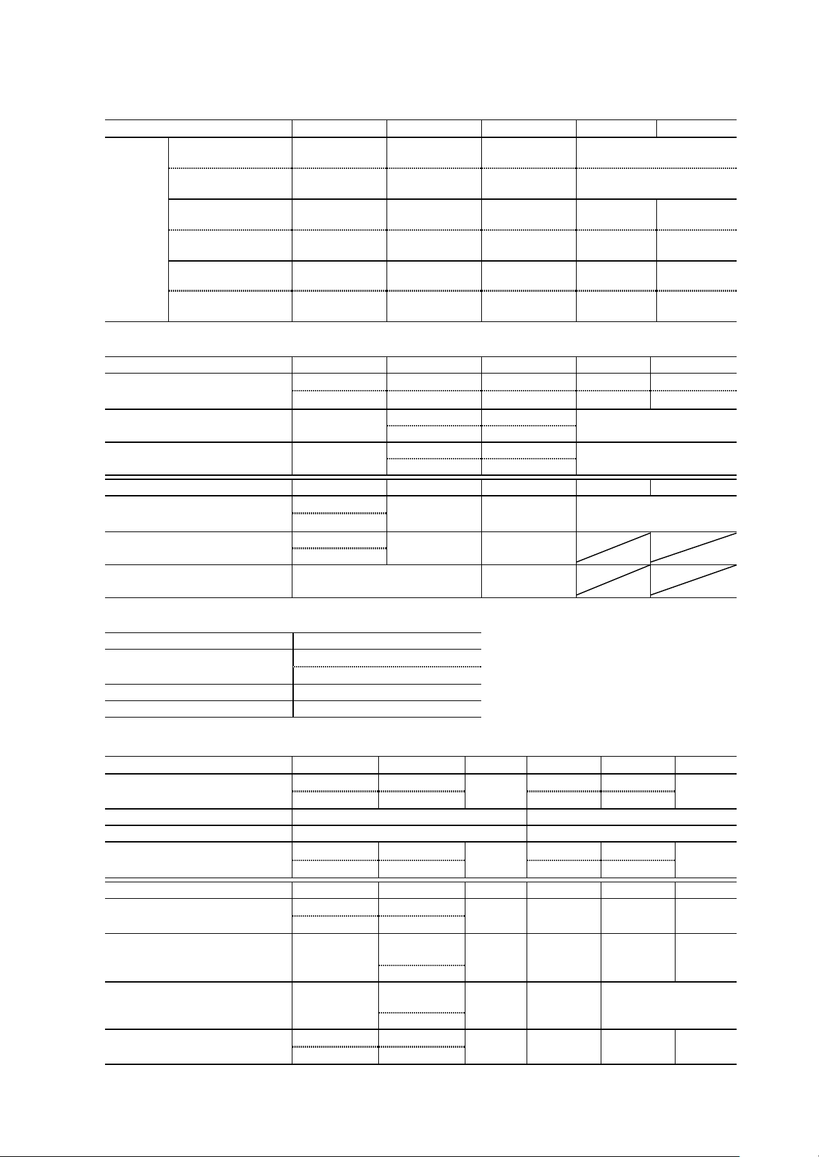
4.7.1 Power Supply Unit (MDS -B-CVE, MDS-C1-CV Series)
Capacity [kW] 3.7~7.5 11.0~18.5 22.0~37.0 45.0 55.0
Terminal
Screw
Size
P, N
(L+, L-)
Screw Torque
[lb in/ N m]
L11, L21, MC1
(R0, S0)
Screw Torque
[lb in/ N m]
L1, L2, L3 M4 M5 M8 M8 M10
M6 M6 M6 M6, M10
44.3/5.0 49.6/5.6 49.6/5.6 49.6/5.6, 177/20
M4 M4 M4 M4 M4
17.4/2.0 14.2/1.6 14.2/1.6 14.2/1.6 14.6/1.6
Screw Torque
[lb in/ N m]
14.6/1.6 29.8/3.37 117.2/13.2 117.2/13.2
P, N (L+, L-)
Capacity [kW] 3.7, 5.5 7.5 11.0 15.0 18.5, 22.0
#10/60°C #8/60°C #4/60°C #4/60°C #3/60°C Wire Size (AWG)
/Temp Rating Note 1
Crimping Terminals Type R5.5-6
Crimping Tools Type YHT-2210
#12/75°C #10/75°C #8/75°C #4/75°C #4/75°C
R8-6 R22-6
R5.5-6 R8-6
YHT-8S YPT-60
YHT-2210 YHT-8S
Capacity [kW] 26.0 30.0 37.0 45.0 55.0
#1/60°C Wire Size (AWG)
/Temp Rating Note 1
#3/75°C
Crimping Terminals Type
Crimping Tools Type YPT-60
38-S6
R22-6
#1/75°C #1/0/75°C
38-S6
L330T
459-12
YET300
YF-1
The bus bar is attached to
L11, L21 (R0, S0), MC1
Capacity [kW] 3.7~55.0
#14/ 60°C Wire Size (AWG)
/Temp Rating Note 1
#14/ 75°C
Crimping Terminals Type V2-4
Crimping Tools Type YNT-1614
L1, L2, L3
Capacity [kW] 3.7 5.5 7.5 11.0 15.0 18.5
/Temp Rating Note 1
#10/60°C #10/60°C #4/60°C #3/60°C Wire Size (AWG)
#12/75°C #10/75°C
#10/75°C
#4/75°C #4/75°C
Crimping Terminals Type 5.5-S4 L300T 459-23
Crimping Tools Type YHT-2210 YPT-60
#10/60°C #10/60°C #4/60°C #3/60°C Earth Wire Size
(AWG)
#10/75°C #10/75°C
#10/75°C
#4/75°C #4/75°C
Capacity [kW] 22.0 26.0 30.0 37.0 45.0 55.0
/Temp Rating Note 1
(AWG)
#1/60°C #1/0/60°C Wire Size (AWG)
#2/75°C #1/75°C
L330T
459-12 Crimping Terminals Type 38-S8
38-S8
YET300
YF-1 Crimping Tools Type YPT-60
YPT-60
#3/60°C #1/60°C Earth Wire Size
#3/75°C #3/75°C
#1/75°C 1/0/75°C
38-S8
YPT-60
L330T
459-12
YET300
YF-1
#3/75°C 1/75°C #1/75°C #1/0/75°C
xiv
177/20
R22-6
YPT-60
the product.
#3/75°C
#3/75°C
#2/0
/75°C
/75°C
70-8 R80-10
YTP-150
#3/0
Page 17

4.7.2 Servo Drive Unit (MDS -B-V1/2/14/24, MDS-C1-V1/2 Series)
Axis 1-axis (V1, V14) 2-axes (V2, V24)
Capacity [kW] 0.1〜3.5 4.5〜9.0
Terminal
Screw
Size
P, N
(L+, L-)
Screw Torque
[lb in/ N m]
L11, L21
(R0, S0)
Screw Torque
[lb in/ N m]
M6 M6 M6 M6
44.3
/5.0
44.3
/5.0
M4 M4 M4 M4
17.4
/2.0
17.4
/2.0
U, V, W M4 M5 M8 M4
Screw Torque
[lb in/ N m]
14.6
/1.6
28.6
/3.2
P, N (L+, L-)
Wire size depends on the Power Supply Unit (MDS-B-CVE, MDS -C1-CV Series).
L11, L21 (R0, S0)
Capacity [kW] 0.1〜15.0
Wire Size (AWG)
/Temp R ating Note 1
#14/ 60°C
#14/ 75°C
Crimping Terminals Type V2-4
Crimping Tools Type YNT-1614
U, V, W
Capacity [kW]
Wire Size (AWG)
/Temp Rating Note 1
Crimping Terminals Type R2-4
Crimping Tools Type YHT-2210
(AWG)
Capacity [kW]
/Temp Rating Note 1
Crimping Terminals Type
Crimping Tools Type YHT-8S YPT-60
(AWG)
0.1〜1.0
#14/60°C #10/60°C #8/60°C #8/60°C
#14/75°C #14/75°C #10/75°C #10/75°C
#14/60°C #10/60°C #8/60°C #8/60°C Earth wire Size
#14/75°C #12/75°C #10/75°C #10/75°C
7.0 9.0 11.0 15.0
#8/60°C #8/60°C #4/60°C #2/60°C Wire Size (AWG)
#8/75°C #8/75°C #4/75°C #3/75°C
R8-5
(8-4)
#8/60°C #8/60°C #4/60°C #3/60°C Earth Wire Size
#8/75°C #8/75°C #4/75°C #3/75°C
2.0 3.5 4.5
R5.5-4 8-4
T2-4 R5.5-4
R8-5 R22-8 R38-8
11.0,
15.0
44.3
/5.0
17.4
/2.0
117.2
/13.2
0.1+0.1〜7.0+7.0
44.3
/5.0
17.4
/2.0
14.6
/1.6
R8-5
(8-4)
R5.5-5
(R5.5-4)
YHT-8S
YHT-2210
xv
Page 18
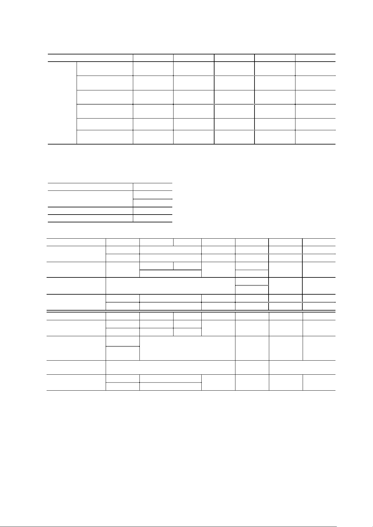
4.7.3 Spindle Drive Unit (MDS -B-SP, MDS-C1-SP Series)
Capacity [kW] 0.4~3.7 5.5~18.5 22.0~30.0 37.0 45.0/55.0
P, N
(L+, L-)
Screw Torque
[lb in/ N m]
Terminal
Screw
Size
L11, L21
(R0, S0)
Screw Torque
[lb in/ N m]
U, V, W M4 M5 M8 M8 M10
Screw Torque
[lb in/ N m]
P, N (L+, L-)
Wire size depends on the Power Supply Unit (MDS -B-CVE, MDS-C1-CV Series).
L11, L21 (R0, S0)
Capacity [kW] 0.4~55.0
/Temp Rating Note 1
Crimping Terminals Type V2-4
Crimping Tools Type YNT-1614
U, V, W
Capacity [kW] 0.4, 0.75 1.5 2.2, 3.7
#14 /60°C
/Temp Rating Note 1
Type
#14 /75°C
R2-4
Crimping Tools Type
#14 /60°C
(AWG)
#14 /75°C
Capacity [kW] 18.5 22.0 26.0 30.0 37.0 45.0 55.0
Wire Size (AWG)
/Temp Rating Note 1
Crimping Terminals
Type
#3/60°C #2/60°C #1/60°C
#4/75°C #3/75°C #2/75°C
22-S6
L330T
459-23
Crimping Tools Type
#3/60°C #3/60°C Earth Wire Size
(AWG)
#4/75°C #3/75°C
Note 1: 60°C: Polyvinyl chloride insulated wires (IV)
75°C: Grade heat -resistant polyvinyl chloride insulated wires (HIV)
Use copper wire only.
Above listed wire are for use in the electric cabinet on machine or equipment.
M6 M6 M6 M10 M10
44.3/5.0 44.3/5.0 44.3/5.0 234.3/26.5 177/20
M4 M4 M4 M4 M4
17.4/2.0 17.4/2.0 17.4/2.0 17.4/2.0 17.2/2.0
14.6/1.6 28.6/3.2 117.2/13.2 88.5/10.0 177/20
#14/60°C Wire Size (AWG)
#14/75°C
5.5 7.5 11.0 15.0
#10/60°C #10/60°C #8/60°C #8/60°C #4/60°C Wire Size (AWG)
#14/75°C #12/75°C #10/75°C #8/75°C #4/75°C
5.5-S4 R5.5-4 R8-5 Crimping Terminals
R2-4
YHT-2210
R5.5-5
R5.5-5
YHT-8S
YHT-2210
R8-5
YHT-8S YPT-60
#11/60°C #10/60°C #8/60°C #8/60°C #4 /60°C Earth Wire Size
#14/75°C #10/75°C #10/75°C #8/75°C #4 /75°C
#1/75°C #1/0/75°C
#2/0
75°C
R38-8 R60-8 70-10 R100-10
YPT-60
YET300
YF-1
YPT-150
#3/75°C #1/75°C #1/75°C
L330T
459-23
#4/0
/75°C
#3/0
/75°C
xvi
Page 19
4.8 Spindle Drive / Motor Combinations
Following combinations are the Standard combinations
Rating Output (kW)
Drive Unit Note: 1
MDS-B-SP []-04
MDS-C1-SP []-04
MDS-B-SP []-075
MDS-C1-SP []-075
MDS-B –SP []-15
MDS-C1-SP []-15
MDS-B –SP []-22
MDS-C1-SP []-22
MDS-B –SP []-37
MDS-C1-SP []-37
MDS-B-SP []-55
MDS-C1-SP []-55
MDS-B-SP []-75
MSD-C1-SP []-75
MDS-B-SP []-110
MDS-C1-SP []-110
MDS-B-SP []-150
MDS-C1-SP []-150
MDS-B-SP []-185
MDS-C1-SP []-185
MDS-B-SP []-220
MDS-C1-SP []-220
MDS-B-SP []-260
MDS-C1-SP []-260
MDS-B-SP []-300
MDS-C1-SP []-300
MDS-B-SP [] –370
MDS-B-SP [] -450
MDS-B-SP [] -550
SJ- ( ) Series
SJ-V/VL Series
Note 1: [] can be H, M, X, HX, MX or none.
Note 1: Applicable unit depends on the range of power constant of motor.
Inquire of Mitsubishi about the detail of the combinations.
Of Applicable Spindle Motor
SJ-N Series
Note: 2
0.2
0.75
1.5
2.2 2.2
3.7 3.7
5.5 5.5
5.5
7.5
5.5
7.5
11
7.5
11
15
11
15
18.5
11
15
18.5
22
11
15
18.5
22
26
15
18.5
22
26
30
15
18.5
22
26
30
37
22
26
30
37
45
30
37
45
55
SJ-NL Series
7.5
11
xvii
Page 20
CN1B CN1A CN4 CN9 CN3L CN2L CN3
CN23 CN2
CN1B CN1A CN4 CN9 CN6 CN5 CN8 L+/L-L11/L21
CN7 MDS-C1-V1/V2 Series
MDS-C1-SP[H][M]
[X]
Series
MDS-C1-CV Series
From NC
External Emergency Stop
Regarding the connection of NC,
Refer to specification manual
CN4 Enclosure Side
Machine Side
Servo Motor
Spindle Motor
Encoder
FAN Servo Motor
Encoder
Battery
Unit
MC1MC
MU/MV/MW
L1/L2/L3
U/V/W LU/LV/LW
Contactor
Fuse or
AC-L 3-
phase
CN9 MC Encoder and
Thermal Protection
5. AC Servo/Spindle System Connection
see the NC manual book.
MDS-B-V1/V2 Series
MDS-B-V14/V24 Series
MDS-B-SP(H)(M)[X] Series
MDS-B-CVE Series
or
Terminator A-TM
BNP-C3000
AC reactor
Breaker
200/220VAC
Circuit Breaker
xviii
Page 21

CONTENTS
Chapter I MDS-C1 Series Servo/Spindle System Configuration Section
1. Outline .................................................................................................................... I-2
2. Drive Section System Configuration ............................................................................... I-4
3. Unit Installation ............................................................................................................... I-12
4. Connection of Each Unit ................................................................................................. I-16
4.1 Layout of each unit ................................................................................................. I-17
4.2 Link bar specifications ............................................................................................ I-17
4.3 Unit separated layout ............................................................................................. I-19
4.4 Precautions for installing multiple power supply units ............................................ I-20
4.5 Precautions for installing only one power supply unit for the
2CH communication specifications with the NC (For 2-system control).................. I-21
4.6 Connection of battery unit ...................................................................................... I-22
4.6.1 Battery unit...................................................................................................... I-22
4.6.2 Connection...................................................................................................... I-22
5. Drive Section Connector and Cable Specifications ........................................................ I-24
5.1 Half pitch cable connection system ........................................................................ I-24
5.2 Cable details .......................................................................................................... I-26
5.2.1 Communication cable SH21 (semi ordered product) ..................................... I-26
5.2.2 Terminator A -TM (ordered part) .................................................................... I-26
5.2.3 Servo drive unit detector cable ...................................................................... I-27
5.2.4 Brake cable .................................................................................................... I-29
5.2.5 Communication cable SH21 connector ......................................................... I-30
5.2.6 Cannon plug for servomotor detector ............................................................ I-31
5.2.7 Cable wire ...................................................................................................... I-33
5.2.8 Cable protection tube (noise countermeasure) ............................................. I-34
5.2.9 Oil-proof type servomotor cable connectors (Recommendation 1) ............... I-35
5.2.10 Oil-proof type servomotor connectors (Recommendation 2) ......................... I-36
5.2.11 Cable clamp ................................................................................................... I-37
5.2.12 Spindle control circuit cable list ...................................................................... I-38
5.2.13 Cable assembly pro cedure (Excluding SH21 cable)....................................... I-53
6. Outline Drawing .............................................................................................................. I-58
6.1 Panel installation structure ..................................................................................... I-58
6.2 Power supply unit ................................................................................................... I-59
6.3 1-axis servo drive unit/2-axis servo drive unit/spindle servo drive unit ................... I-60
6.4 Battery unit............................................................................................................... I-61
6.5 AC reactor................................................................................................................ I-62
6.6 Dynamic brake unit.................................................................................................. I-63
6.7 Contactor ................................................................................................................ I-63
6.8 Circuit Breaker (CB) ................................................................................................. I-63
7. Heating Value ................................................................................................................. I-66
8. Selection of Capacity....................................................................................................... I-68
8.1 Selection of the power supply unit capacity............................................................. I-68
8.1.1 Selection with rated capacity (continuous rated capacity)............................... I-68
8.1.2 Selection with maximum momentary rated capacity....................................... I-70
8.1.3 Selection data .................................................................................................. I-70
8.1.4 Selection example........................................................................................... I-71
8.2 Selection of leakage breaker................................................................................... I-72
8.3 Noise filter................................................................................................................ I-73
8.4 Selection of power supply capacity ........................................................................ I-75
8.5 Selection of wire size ............................................................................................. I-76
8.6 Selection of AC reactor, contactor and CB ............................................................ I-81
i
Page 22

Chapter II MDS-C1-CV Power Regeneration Type Power Supply Section
1. Power Regeneration Type Power Supply........................................................................ II-2
1.1 C1-CV Outline ........................................................................................................ II-2
1.2 Model configuration ................................................................................................. II-2
1.3 List of unit models and outlines................................................................................ II-3
1.4 List of specifications ............................................................................................... II-7
1.5 Hardware and parameter setting ............................................................................ II-9
1.6 Status display ......................................................................................................... II-10
1.6.1 7-segment LED display ................................................................................. II-10
1.6.2 Charge lamp .................................................................................................. II-10
1.7 List of alarms and warnings ................................................................................... II-11
1.8 Explanation of connectors and terminal block ........................................................ II-13
1.9 Power supply external emergency stop function..................................................... II-14
1.10 Main circuit connection ........................................................................................... II-17
Chapter III MDS-C1-Vx Servo System Section
1. Outline .................................................................................................................... III-2
2. Motor .................................................................................................................... III-4
2.1 Outline .................................................................................................................... III-4
2.2 Model configuration ................................................................................................ III-5
2.3 Main equipment list ................................................................................................ III-7
2.4 Specifications list .................................................................................................... III-8
2.5 Torque characteristics.............................................................................................. III-15
2.6 Duty drive characteristics......................................................................................... III-22
2.7 Outline dimension drawings ................................................................................... III-25
2.8 Motor connection .................................................................................................... III-43
2.9 Motors with electromagnetic brake ........................................................................ III-48
2.10 Motor vibration resistance ...................................................................................... III-53
2.11 Motor shaft strength ............................................................................................... III-54
2.12 Environmental conditions......................................................................................... III-56
3. Detectors .................................................................................................................... III-58
3.1 List of detector specifications ................................................................................. III-58
3.2 Serial pulse en coder .............................................................................................. III-59
3.2.1 Features ........................................................................................................ III-59
3.2.2 Types ............................................................................................................. III-59
3.2.3 Outline dimension drawings .......................................................................... III-60
3.2.4 Cable connection diagram ............................................................................. III-63
3.2.5 Maintenance .................................................................................................. III-64
3.3 Scale I/F unit............................................................................................................ III-65
3.3.1 Outline............................................................................................................. III-65
3.3.2 Model configuration......................................................................................... III-65
3.3.3 List of specifications ........................................................................................ III-65
3.3.4 Unit outline dimension drawing....................................................................... III-66
3.3.5 Description of connector .................................................................................. III-67
3.3.6 Example of scale I/F unit connection ............................................................. III-68
3.3.7 Cables............................................................................................................. III-70
4. Servomotor and Detector Installation ............................................................................. III-72
4.1 Installation .............................................................................................................. III-72
4.2 Coupling with the load ............................................................................................ III-76
ii
Page 23

5. MDS-C1-V1 Servo Drive ................................................................................................ III-80
5.1 Availability of 2-system
(standard drive unit mode and high-gain drive unit mode) ..................................... III-80
5.2 Model configuration ................................................................................................. III 81
5.3 Specifications list .................................................................................................... III-82
5.4 Connection of dynamic brake unit ........................................................................ III-85
5.5 Hardware setting .................................................................................................... III-87
5.6 Parameter settings ................................................................................................. III-88
5.6.1 Standard Parameters (Standard Drive unit).................................................... III-89
5.6.2 High-gain Parameters (High-gain Drive unit).................................................. III-113
5.7 Alarms and Warnings ............................................................................................. III-138
5.8 Explanation of connector and terminal block ......................................................... III-147
5.9 Main circuit and brake connection .......................................................................... III-148
5.9.1 Main circuit .................................................................................................... III-148
5.9.2 Brake ............................................................................................................. III-150
5.10 Wiring system diagrams for systems ..................................................................... III-151
5.11 D/A output function ................................................................................................. III-154
5.11.1 Outline ........................................................................................................... III-154
5.11.2 Hardware specifications ................................................................................ III-154
5.11.3 Parameters .................................................................................................... III-154
5.11.4 Output data No. ............................................................................................. III-155
5.11.5 Setting of output magnification ...................................................................... III-155
5.11.6 Others ............................................................................................................ III-156
6. MDS-C1-V2 Servo Drive ................................................................................................ III-158
6.1 Model configuration ................................................................................................ III-158
6.2 Servo drive unit specifications ................................................................................ III-159
6.3 Hardware setting .................................................................................................... III-163
6.4 Status display ......................................................................................................... III-164
6.5 Explanation of terminal block and connectors ........................................................ III-166
6.6 Main circuit connection ........................................................................................... III-167
7. Selection of Capacity ...................................................................................................... III-170
7.1 Selection of servo system ...................................................................................... III-170
7.1.1 Types of drive systems .................................................................................. III-170
7.1.2 Selection of servomotor ................................................................................. III-171
7.2 Determining the coasting amount with emergency stop ........................................ III-182
Chapter IV MDS-C1-SP Spindle S ystem Section
1. Outline .................................................................................................................... IV-2
1.1 Features of the MDS-C1-SP spindle system ......................................................... IV-2
1.2 Precautions for use .................................................................................................. IV-2
1.3 Model configuration ................................................................................................ IV-3
1.4 Configuration .......................................................................................................... IV-4
1.4.1 Basic configuration (no added functions) ...................................................... IV-4
1.4.2 With orientation function ................................................................................ IV-4
1.4.3 High-speed synchronous tap/spindle synchronization/with
orientation function ........................................................................................ IV-6
1.4.4 OSE90K+1024 encoder C-axis control/with orientation function ................... IV-7
1.4.5 OSE90K+1024 encoder C-axis control and high-speed synchronous tap/
spindle synchronization/with orientation function .......................................... IV-8
1.4.6 MBE90K encoder C -axis control/with orientation function ............................. IV-9
1.4.7 MBE90K encoder C -axis control and high-speed synchronous tap/
spindle synchronization/with orientation function .......................................... IV-9
1.4.8 MHE90K encoder C-axis control/with orientation function ............................ IV-10
1.4.9 MHE90K encoder C-axis control and high-speed synchronous tap/
spindle synchronization/with orientation function .......................................... IV-10
1.5 Device-to-device connections .............................................................................. IV-11
iii
Page 24

2. Specifications................................................................................................................... IV-14
2.1 AC spindle motor and controller specifications ...................................................... IV-14
2.2 Output characteristics ............................................................................................ IV-19
2.3 Outline dimension drawings ................................................................................. IV-22
2.3.1 Motor ............................................................................................................. IV-22
3. Status Display and Parameter Settings ........................................................................... IV-30
3.1 Status display with 7-segment LED......................................................................... IV-30
3.2 Spindle parameters.................................................................................................. IV-31
3.3 Spindle specification parameters screen................................................................. IV-60
3.4 Spindle monitor screen............................................................................................ IV-64
3.5 Control input signals ................................................................................................ IV-68
3.6 Control output signals.............................................................................................. IV-71
3.7 Meter outputs........................................................................................................... IV-74
3.8 Output interface....................................................................................................... IV-76
3.9 Spindle protection/warning functions....................................................................... IV-77
4. Optional Specifications and Parts................................................................................... IV-80
4.1 Orientation specifications (optional)........................................................................ IV-80
4.1.1 1-point orientation using magnetic sensor..................................................... IV-80
4.1.2 4096-point orientation using encoder............................................................. IV-88
4.1.3 4096-point orientation using motor built-in encoder....................................... IV-91
4.1.4 Operation of orientation .................................................................................. IV-91
4.2 Synchronous tap function (option).......................................................................... IV-94
4.2.1 Closed type synchronous tap......................................................................... IV-94
4.2.2 Semi-closed type synchronous tap................................................................ IV-94
4.2.3 Operation of synchronous tap ........................................................................ IV-94
4.3 C-axis control (optional).......................................................................................... IV-95
4.3.1 When using encoder (OSE90K+1024 BKO-NC6336H01)............................. IV-95
4.3.2 When using built-in encoder (MBE90K)......................................................... IV-98
4.3.3 When using built-in encoder (MHE90K)......................................................... IV-98
4.4 Single parts (optionally supplied parts)................................................................... IV-99
4.4.1 Power step-down transformer........................................................................ IV-99
4.4.2 Noise filter ....................................................................................................... IV-101
4.5 Other optional specifications................................................................................... IV-103
4.6 Theoretical acceleration and deceleration times.................................................... IV-104
Chapter V IPM Spindle Drive System Section
1. Outline .................................................................................................................... V-2
1.1 Outline .................................................................................................................... V-2
1.2 Features of MDS-C1-SPM Series........................................................................... V-2
1.3 Precautions for use ................................................................................................ V-2
2. Configuration of Drive System ........................................................................................ V-4
2.1 Basic system configuration drawing ....................................................................... V-4
2.2 Combination with power supply unit....................................................................... V-4
2.3 List of IPM spindle drive units ............................................................................... V-5
3. Setting the IPM Spindle Drive Unit Parameters.............................................................. V-8
3.1 Bit selection parameters .......................................................................................... V-8
3.2 Setting the unit type, motor and power supply unit ................................................ V-10
3.3 Spindle monitor screen .......................................................................................... V-11
3.4 List of spindle protect ion functions and warning functions..................................... V-15
iv
Page 25

4. Setup Procedures ............................................................................................................ V-18
4.1 Wiring the drive unit ................................................................................................ V-18
4.2 Setting the parameters............................................................................................ V-18
4.3 PLG Z -phase automatic adjustment ..................................................................... V-18
4.4 PLG automatic adjustment of SPM unit.................................................................. V-19
4.5 Alarms .................................................................................................................... V-19
4.6 Handling the motor.................................................................................................. V-19
4.6.1 Storage ............................................................................................................. V-19
4.6.2 Assembly (built-in type).................................................................................... V-19
5. IPM Spindle Motor Specifications .................................................................................... V-22
5.1 IPM spindle motor specifications............................................................................ V-22
5.2 Motor outline drawings............................................................................................ V-23
Appendix 1 EN Standards Step -down Insulation Transformer.................................... AI-2
Appendix 2 EMC Installation Guidelines....................................................................... AII-2
1. Introduction................................................................................................................... AII-2
2. EMC Instructions.......................................................................................................... AII-2
3. EMC Measures............................................................................................................. AII-3
4. Measures for panel structure........................................................................................ AII-3
4.1 Measures for control box unit.......................................................................... AII-3
4.2 Measures for door........................................................................................... AII-4
4.3 Measures for operation board panel............................................................... AII-4
4.4 Shielding of the power supply input section.................................................... AII-4
5. Measures for various cables......................................................................................... AII-5
5.1 Measures for wiring in box.............................................................................. AII-5
5.2 Measures for shield treatment......................................................................... AII-5
5.3 Servomotor power cable................................................................................. AII-6
5.4 Servomotor feedback cable ............................................................................. AII-6
5.5 Spindle motor power cable.............................................................................. AII-7
5.6 Spindle motor feedback cable......................................................................... AII-7
5.7 Cable between control box and operation board panel................................... AII-7
6. EMC Countermeasure Parts ........................................................................................ AII-8
6.1 Shield clamp fitting.......................................................................................... AII-8
6.2 Ferrite core...................................................................................................... AII-9
Appendix 3 Unit system.................................................................................................. AIII -2
Appendix 4 Classification of Servo/Spindle Drive Unit Circuits Based on
Higher Harmonic Suppression Countermeasures Guidelines.............. AIV-2
Appendix 5 Explanation of Large Capacity Spindle Unit Specifications.................. AV-2
1. Outline .................................................................................................................... AV-2
2. List of units................................................................................................................... AV-2
3. Selection of AC reactor (B-AL), contactor and CB .................................................... AV-2
4. Outline of units............................................................................................................. AV-3
5. Panel cut dimension drawing....................................................................................... AV-4
6. Detailed outline drawing .............................................................................................. AV-5
7. Heating value............................................................................................................... AV-8
8. Selection of power capacity......................................................................................... AV-8
9. Selecting the wire size................................................................................................. AV-8
10. Drive unit connection screw size................................................................................ AV-9
11. Connection of each unit.............................................................................................. AV-9
12. Restrictions................................................................................................................. AV-11
13. Parameters................................................................................................................. AV-12
14. Precautions................................................................................................................. AV-12
v
Page 26

Page 27

I. MDS-C1 Series
Servo/Spindle System Configuration
Section
Page 28

Page 29

1. Outline
1. Outline .................................................................................................................... I-2
I - 1
Page 30

1. Outline
1. Outline
MDS-C1 Series servo and spindle system outline
The MDS-C1 Series is MELDAS drive system that has been developed totally connected the servo drive
and spindle drive sections.
The MDS-C1 Series is the successor to the MDS-B Series, and has been developed to satisfy European
Safety Standards. This Series has the following features.
(1) Compact and lightweight
The converters that were conventionally built in each servo and spindle drive have been integrated into
one unit. The drive system volume, installation area and weight have been drastically reduced with the
incorporation of high density mounted electronic parts IGBT-IPM (Intelligent Power Module) and the
high performance heat radiating fin.
(2) Standardization of dimensions
The outline has been standardized to the book end type, and by unifying the height and depth
dimensions, installation in control box has been made easy. Furthermore, by matching the shape with
the NC unit (M500 Series), an integrated appearance with the NC has been realized.
(3) Low heat generation
By incorporating the IPM and using power supply regeneration in the servo drive, the amount of heat
generated has been greatly reduced.
(4) High speed and precision processing
A high speed CPU has been mounted on the control PCB, and a 100,000 pulse/rotation sub micron
detector has been incorporated as a standard to allow faster and more precise interpolation.
By incorporating the stable position loop control (SHG control) method, having an outstanding
response, the positioning time and tracking have been improved and the machine vibration during
acceleration/deceleration has been reduced.
The cutting performance and cutting precision during position control have been improved by using the
high speed CPU also for the spindle drive.
(5) High speed spindle orientation
Smooth operations and minimum orientation times have been realized by using the high speed
orientation method while allows direct orientation from the high speed during the spindle drive.
(6) Features of the MDS -C1 Series
(a) European Safety Standards compliant
This Series complies with the European Safety Standards (LVD Directives). (Refer to the section
"Compliance to European EC Directives" for details.)
(Note that the C1 Series target units are limited to the CV (power regeneration power supply), SP
(spindle drive) and V1/V2 (1, 2-axis servo drive).)
(b) Addition of power supply emergency stop input line
With the C1 Series , the external contactor can be directly shut off from the power supply even
when the emergency stop hot line from the NC does not function for any reason.
(This function is validated with the rotary switch and connected drive parameter settings. Thus, the
functions do not change from the conventional functions when used in the same manner as the A
Series.)
I - 2
Page 31

2. Drive Section System Configuration
2. Drive Section System Configuration .............................................................................. I-4
I - 3
Page 32

+
–
2. Drive Section System Configuration
2. Drive Section System Configuration
WARNING
1. Wiring and inspection work must be done by a qualified technician.
2. Wait at least 15 minutes after turning the power OFF before starting wiring or inspections. Failure
to observe this could lead to electric shocks.
3. Wire the servo drive unit and servomotor after installation. Failure to observe this could lead to
electric shocks.
4. Do not damage, apply forcible stress, place heavy items or engage the cable. Failure to observe
this could lead to electric shocks.
CAUTION
1. Correctly carry out the wiring. Failure to do so could lead to runaway of the servomotor, or to
injuries.
2. Do not mistake the terminal connections. Failure to observe this item could lead to ruptures or
damage, etc.
3. Do not mistake the polarity (
item could lead to ruptures or damage, etc.
4. Do not reverse the direction of a diode which connect to a DC
relay for the control output signals to suppress a surge.
Connecting it backwards could cause the drive unit to
malfunction so that signals are not output, and emergency
stop and other safety circuits are inoperable.
5. Reduce magnetic damage by installing a noise filter,etc. The
electronic devices used near the servo drive unit could be
affected by magnetic noise.
6. Do not install a condensing capacitor, surge absorber or radio noise filter on the output side of
the servo drive unit.
7. Provide a sequence that shut off the power at the regenerative resister error signal-ON when
using the regenerative resistor. The regenerative resistor could abnormally overheat and cause a
fire due to a fault in the regenerative transistor, etc.
8. Never make modifications.
9. Some parts are the MDS -C1 Series instead of the MDS-B Series. The basic specifications do
not differ, but if newly added functions or a newly added capacity is being used, always confirm
the changed points before starting use.
,
). Failure to observe this
Servo drive unit
COM
(24VDC)
Control output
signal
RA
CAUTION
Cautions for using MDS -C1 Series
1. The power supply unit MDS -C1-CV-370 has a different rush sequence from the other power
supplies. Thus, always install an external contactor. Do not share the contactor with other power
supplies.
2. The servo drive unit MDS-C1-V1-110/150 does not have built-in dynamic brake. Thus, always use
an external dynamic brake unit.
I - 4
Page 33

-
Spindle
11kW, 15kW
B-AL
(c)
(c)
(b) (a)
2. Drive Section System Configuration
(1) Basic system configuration (Example: Spindle + 3-axis servo)
Servo motor
Servo
motor
(c)
Servo
drive unit
(2-axis)
Servomotor
(c)
Servo
drive unit
(1-axis)
Link bar
motor
Spindle
drive unit
(Note 1)
Power
supply
unit
Control power supply
Power supply RST
(Note 3)
Con-tac
tor
AC
reactor
CB1
200VAC
IN
Servomotor fan
Spindle motor fan ST
(Note 1) In systems which use a spindle drive unit, the spindle drive unit must be placed next to the
power supply unit as shown above. Also install the 11kW and higher servo drive unit next to
the power supply unit.
If also using spindle drive units, arrange the units next to the power supply in decreasing
order of drive capacity size.
(Note 2) Excluding MDS -C1-CV-370, the use of a contactor can be selected.
Excluding MDS -C1-CV-370, use is possible without a contactor, but use of a contactor is
recommended for safety purposes.
The rotary switch on the power supply unit must be set as follows according to whether the
contactor is installed.
Contactor installed............ Rotary switch setting = 0
Contactor not installed....... Rotary switch setting = 1
I - 5
CB2
Page 34

1
A1
C1
D1
A0
2. Drive Section System Configuration
(2) List of units
(a) Power supply unit ..... DC power supply to drive unit/regenerative control
Model
No.
MDS-
C1-CV-37 3.7 380∗60∗200
2 C1-CV-55 5.5 380∗60∗200
3 C1-CV-75 7.5 380∗60∗200
4 C1-CV-110
5 C1-CV-150
6 C1-CV-185
7 C1-CV-220
8 C1-CV-260
9 C1-CV-300
10 C1-CV-370
11 A-CR-10 1.0 380∗60∗180
12 A-CR-15 1.5 380∗60∗180
13 A-CR-22 2.2 380∗60∗180
14 A-CR-37 3.7 380∗60∗180
15 A-CR-55 5.5 380∗60∗180
16 A-CR-75 7.5 380∗60∗180
17 A-CR-90 9.0 380∗60∗180
Capacity
(kW)
11.0 380∗90∗255 B1
15.0 380∗120∗255
18.5 380∗120∗255
22.0 380∗150∗255
26.0 380∗150∗255
30.0 380∗150∗255
37.0 380∗150∗255
Dimensions
(H∗W∗Dmm)
Type
Correspondence to drive unit capacity when single spindle is used (kW)
0.4 0.75 1.5 2.2 3.7 5.5 7.5 11 15 18.5 22 26 30 37 45 55
I - 6
Page 35

2. Drive Section System Configuration
(b) Spindle drive unit ... Spindle motor control
Model
No.
MDS-C1-
1 SP -04 0.4 380∗60∗180 CV-37
2 SP -075 0.75 380∗60∗180 CV-37
3 SP -15 1.5 380∗60∗180
4 SP -22 2.2 380∗60∗255 CV-37
5 SP -37 3.7 380∗60∗255
6 SP -55 5.5 380∗90∗255 CV-55
7 SP -75 7.5 380∗90∗255 CV-75
8 SP -110 11.0 380∗90∗255 CV-110
9 SP -150S 15.0 380∗90∗255
10 SP -150 15.0 380∗120∗255 CV-150
11 SP -185 18.5 380∗120∗255
12 SP -220 22.0 380∗150∗255 D1
13 SP -260 26.0 380∗150∗255 CV-260
14 SP -300 30.0 380∗150∗255
Capacity
(kW)
Dimensions
(H∗W∗Dmm)
Type
Power supply unit
for single spindle
A0
A1
B1
C1
D2
Remarks
CV-37
CV-37
CV-150
CV-185
CV-220
CV-300
I - 7
Page 36

52 53
52 53
2. Drive Section System Configuration
(c) Servo drive unit Adaptable motor
Model
of
MDS-
axes
V1-01 0.1
V1-03 0.3
V1-05 0.5
V1-10 1.0
V1-20 2.0
V1-35 3.5
V1-45S
V1-45 4.5
1-axis type
V1-70S
V1-70 7.0
V1-90 9.0
V1-110
V1-150
C1-
Capacity
(kW)
4.5
7.0
11.0
15.0
Dimen-
sions
Type
A0
A1
B1
C1
D2
Axis
102 103 152 153 202 203 352 353 452 453 702 703 902
HCo o o No.
(Note) Limits apply to continuous operation of V1-45S and V1-70S.
(c) Servo drive unit Adaptable motor
Model
of
MDS-
axes
C1-
V2-0101 0.1+0.1
V2-0301 0.3+0.1
V2-0303 0.3+0.3
V2-0501 0.5+0.1
V2-0503 0.5+0.3
V2-0505 0.5+0.5
V2-1005 1.0+0.5
V2-1010 1.0+1.0
V2-2010 2.0+1.0
V2-2020 2.0+2.0
V2-3510S
V2-3520S
2-axis type
V2-3510 3.5+1.0
V2-3520 3.5+2.0
V2-3535 3.5+3.5
V2-4520 4.5+2.0
V2-4535 4.5+3.5
V2-7070S
V2-4545 4.5+4.5
V2-7035 7.0+3.5
V2-7045 7.0+4.5
V2-7070 7.0+7.0
Capacity
(kw)
3.5+1.0
3.5+2.0
7.0+7.0
Dimen-
sions
Type
A0
A1
B1
C1
D1 LM
Axis
LM
L
M
LM
L
M
L
M
LM
L
M
LM
L
M
LM
L
M
L
M
L
M
L
M
LM
L
M
L
M
LM
LM
L
M
L
M
102 103 152 153 202 203 352 353 452 453 702 703 902
HCo o o No.
(Note) Limits apply to continuous operation of V2-7070S.
I - 8
Page 37

Outline dimensions
W:150
D:
255
Fin
(3) List of unit dimensions
2. Drive Section System Configuration
of each unit
A0/A1 B1 C1 D1/D2
Outline type
Outline drawing
(mm)
Fin section D: 75
(Including wind passage
space of 15)
D: 255
180
H: 380
The A0 type has no fin.
(Depth: 180)
W: 60
Fin section D: 75
(Including wind
passage space of 15)
D: 255
H: 380
W: 90
Fin section D: 75
(Including wind
passage space of 15)
D: 255
H: 380
W: 120
Fin section D: 75
(Including wind passage spaces
of D1: 15, D2: 12)
フィン部D:
(風路スペース15含)
H: 380
75
W: 150
Precautions
The depth of the fin section for the MDS-C1 Series is smaller than the MDS-A/B Series due to the high
efficiency radiation of heat structure.
Provide a wind passage space of 15mm or more behind the fins so that the cold air can pass through.
(Provide 12mm or more for the D2 type.)
Units with an "S" at the end of the model have a smaller unit width than the existing series.
Thus, when designing the control box with this unit's outline dimensions, there may be cases when the
existing drive unit cannot be installed.
I - 9
Page 38

Page 39

3. Unit Installation
3. Unit Installation ................................................................................................................ I-12
I - 11
Page 40

3. Unit Installation
3. Unit Installation
CAUTION
1. Correctly transport the product according to its weight.
2. Do not stack products past the limit.
3. Install servo drive unit, servomotor and regenerative resistor unit on noncombustible material.
Direct installation on combustible material or near combustible material could lead to fires.
4. Follow this Instruction Manual and install the unit in a place where the weight can be borne.
5. Do not get on top of or place heavy objects on the unit.
6. Store and use the units under the designated environmental conditions.
7. Do not allow conductive matter such as screw or cutting chips or combustible matter such as oil
enter the servo drive unit or servomotor.
8. Do not block the intake or exhaust ports of the servomotor provided with a cooling fan.
9. The servo drive unit and servomotor are precision devices, so do not drop or apply strong impacts
on them.
10. Do not install or operate servo drive units or servomotors that are damaged or that have missing
parts.
11. When storing the unit for a long time, contact the Service Center or Service Station.
(1) Each unit is designed to be installed in a cabinet such as a power distribution box. Avoid installation in
direct sunlight, near heat generating objects or outdoors.
(2) The inner working environment (temperature, humidity, vibration, atmosphere) of the cabinet must be
within the limits given in the "Specifications for each unit". The cabinet for the cutting machine must b e
a totally closed type cabinet.
(3) Make considerations so that inspections and replacement during maintenance is easy.
The required space around each unit is shown in the outline dimensions drawing.
(4) Each unit generates some heat, so leave a space on the top and bottom when installing other
equipment or parts.
Refer to the outline drawing for the square hole dimensions. In this case, insert packing between the
unit and power distribution box. Refer to the following installation examples for the installation of the
servo drive unit.
I - 12
Page 41

Fin
40 or more
Fin 40 or more
Power distribution
3. Unit Installation
(5) Provide a structure that separates the intake and outtake. If the air behind the fin is not discharged
properly, causing heat to accumulate, always install the forced outtake fan.
40 or more
160 or more
Power distribution
box
Front
Rear
Example 1. Leave space for air flow when the
power distribution box is at the rear of
the machine.
If heat accumulates behind the fin,
install forced air cooling (FAN) to
discharge the heat.
40 or more
Cover
box
Outtake
Intake
Filter
Outtake
[Unit: mm]
Example 2. When the outdoor air cooling section is to
protrude from the power distribution box,
make sure that cutting chips, etc., do not
enter the outtake section.
If heat accumulates behind the fin, install
forced air cooling (FAN) to discharge the
heat outside the box.
CAUTION
1. Do not hold the front cover when transporting the servo drive unit. The unit could drop.
2. Always observe the installation directions.
3. Secure the specified distance between the servo drive unit and control panel, or between the
servo drive unit and other devices.
Note 1. When installing in a poor environment (factories with large quantities of oil mist), install a filter
on the intake section.
Note 2. When assembling the control box, make sure that drill cutting chips, etc., do not enter the
drive unit.
Note 3. Make sure that oil, water and cutting chips do not enter the drive unit from the control box
clearances or fan on top of the control box .
Note 4. When the unit is at the places having high levels of toxic gases or dust, protect the drive unit by
air purging (preventing the entry of toxic gases and dust by feeding clean air from an external
source, so that inner pressure of control panel is higher than the outside air).
I - 13
Page 42

Wind
Wind direction
(Additionally installed by user)
Inside box
(6) Installation of cooling fan
Each unit (excluding types without fin) are individually provided with cooling fans. If the area around the
fan becomes hot (if heat builds -up), install an agitating fan.
Refer to 1) or 2) below according to the panel structure, and install.
(a) Installing the fan below the heat radiation fins
3. Unit Installation
When using the totally closed type unit
installation method and the box
structure in which cutting oil and dust,
etc., easily enters the unit's fan and fin
direction
section (a structure where the fan may
stop easily due to the working
environment) , the user should install a
fan at the position indicated as FAN.
Forced cooling should then be
performed with a velocity of 2m/s or
higher. Also consider the
maintainability in this case.
(b) Installing the fan above the unit
Due to the structure, heat will tend to accumulate on the top of each unit. Thus, install a fan in the
power distribution box to mix the heat at the top of each unit.
(Inside box)
Outside box
FAN
(Additionally installed by user)
… Install a finger guard for safety.
FAN
I - 14
Servo drive unit (3)
Servo drive unit (2)
Servo drive unit (1)
Spindle drive unit
Power supply unit
Front view of units in power distribution box
Page 43

4. Connection of Each Unit
4. Connection of Each Unit ................................................................................................. I-16
4.1 Layout of each unit ................................................................................................. I-17
4.2 Link bar specifications ............................................................................................ I-17
4.3 Unit separated layout .............................................................................................. I-19
4.4 Precautions for installing multiple power supply units ........................................... I-20
4.5 Precautions for installing only one power supply unit for the
2CH communication specifications with the NC (For 2-system control)............... I-21
4.6 Connection of battery unit ....................................................................................... I-22
4.6.1 Battery unit...................................................................................................... I-22
4.6.2 Connection...................................................................................................... I-22
I - 15
Page 44

NC control
section
servo drive unit)
servo drive unit)
(Spindle drive unit)
(Power supply unit)
(Battery unit)
24VDC
(Note1)
Gro
for C1
L axis
Contactor
Note
M axis
(CB2)
3ø
4. Connection of Each Unit
4. Connection of Each Unit
CAUTION
1. Shut off the power on the servo drive unit side if a fault occurs in the servo drive unit. Fires could
be caused if a large current continues to flow.
2. Provide a sequence that shut off the power at the regenerative resister error signal-ON when
using the regenerative resistor. The regenerative resistor could abnormally overheat and cause a
fire due to a fault in the regenerative transistor, etc.
3. Use a double circuit configuration that allows the operation circuit for the magnetic brakes to be
operated even by the external emergency stop signal.
4. MDS-C1-V1-110/150 does not have built-in dynamic brake. Always use an external dynamic
brake unit.
Wire the power supply and main circuit as shown below.
Always use a Circuit Breaker (CB) on the power supply input wire.
Standard connection
A-BT
C1-CV
C1-SP
C1-V2 (2-axis
und
-V2
B-AL
(CB1)
200VAC 50Hz
200-230VAC 60Hz
(AC reactor)
generate high levels of noise are installed near the
power supply unit and drive unit. If the unit may
malfunction, install a surge killer on the noise
generating device, so as to suppress the noise.
2. Devices (contactor, magnetic brakes, relay) that
C1-V1 (1-axis
Drive section wiring system diagram
I - 16
-25F0-008
-pin half pitch
name
Connector
-pin half pitch
CN1A
-3210-000
CN2A
Page 45

Link bar specifications
Refer to "8. Selection of Capacity" for
8. Selection of Capacity" for
4. Connection of Each Unit
4.1 Layout of each unit
Layout the units according to the following reference as a principle.
(1) When total of spindle motor output and servomotor output is 38kW or less
Σ (Spindle motor output) +kΣ (servomotor output) ≤ 38kW
Servo drive
Servo drive
units
Spindle drive
unit
(Front)
(2) When total of spindle motor output and servomotor output is larger than 38kW
Σ (Spindle motor output) +kΣ (servomotor output) > 38kW
Servo drive
units
Power
supply
unit
No.2
(Front)
Power supply
unit
Spindle
drive
unit
Power
supply
unit
No.1
(K = 1 with 1-axis servo)
(K = 0.7 with 2 or more axes servo)
details.
Link bar
Link bar
(K=1 with only 1-axis servo)
(K=0.7 with 2 or more axes servo)
Refer to "
details.
Link bar
Always connect the power supply unit No. 1
and No. 2 L+ and L– link bars independently.
(Note) The clearance between each unit should generally be 3cm or less.
If the spindle drive unit and servo drive unit must be separated by more than 3cm, observe
the conditions listed in section "4.3".
4.2 Link bar specifications
The link bar is the following part, and must be manufactured by the user:
L+, L–
L11, L21
—— A connection wire used to supply the converter's DC voltage from the power supply unit
to each drive unit.
—— A connection wire used to supply the 200VAC control power to each unit.
This does not necessary need to be a bar (plate), but can be a wire.
—— The terminal block for link bar connection is the following regardless of
the capacity:
L+, L– .......... M6 screw
L11, L21....... M4 screw
An outline connection drawing is shown on the following page for
reference.
CAUTION
I - 17
Page 46

(1) Outline connection drawing
4. Connection of Each Unit
(Note) Mount the terminal cover after wiring as
shown on the left . The terminal cover
differs for each unit width. Refer to
section "8.5" for selecting the wire size.
I - 18
Page 47

L11
L21L+
L11
L21
Wire length 50cm or less
4. Connection of Each Unit
4.3 Unit separated layout
When installing vertically, avoid separating the spindle drive unit (C1-SP) and power supply unit (C1-CV) as
shown in (Example 1) below. Do not separate the 11kW and higher servo drive units either.
When using both spindle drive units and 11kW and higher servo drive units, arrange them next to the power
supply unit in the following order of priority.
V1-150 > V1-110 > SP-300 > SP-260 > SP-185 > SP-150 ………
For example, when using a combination of SP-260 and V1 -150, place the V1-150 next to the power supply
unit, and the SP-260 next to that.
The 9kW and below servo drive unit can be installed vertically as shown in (Example 2). Note that the relay
link bar length must be 50cm or less, and two bars must be bundled.
(Example 1) NG
(Example 2) OK
C1-CV
C1-SP C1-V1 C1-V2
−
L
L11
L21
L+
L
C1-SP C1-CV
L+
L
−
C1-V1 C1-V2
L+
−
−
L
L11
L21
(Note) The above details also apply when separating the units to the left and right and installing.
I - 19
Page 48

L+,L
-
-
L11,L21
4. Connection of Each Unit
4.4 Precautions for installing multiple power supply units
CAUTION
Always use this wiring when using MDS-C1-CV-370. (Refer to "8.1.1 (Note 4)".)
The rush circuit and contactor operation sequence of MDS -C1-CV-370 differs from the other power
supply units (C1-CV). Thus, always install an independent contactor. If the contactor is not used or if
shared with other power supply units, damage will occur.
A system in which a power supply unit (C1-CV (No. 1)) is installed for the spindle drive unit and one
(C1-CV (No. 2)) is installed for the servo drive unit is explained as a representative example of multiple
power supply unit installation. The same connections are used for other multiple installation systems.
NC control section C1-V1 C1-V2 C1-CV (No. 2) C1-SP C1-CV (No. 1) A-BT
L1,L2,L3 L1,L2,L3
200VAC
(1) (2) (3) (4)
CSH21
CN1A CN1B CN1A CN1B
CB2
CB1
AC reactor
Contactor
(5)
CN4
CN4
MCI MCI
L11,L21
MC MC
CN1A CN1B
CN4
Contactor
(6)
CN4
L+,L
AC reactor
Fig. 1
CN1A1
I - 20
(a) Connection of NC communication cable
(i) When battery unit (A -BT) is required (when absolute position detection specifications are
used)
Connect with the lines (1) to (4) in Fig. 1.
(ii) When battery unit (A-BT) is not required (when absolute position detection specifications are
not used).
The (4) connection cable and battery unit will not be required so insert a terminator (A -TM)
into the terminating axis CN1B (C1-SP in Fig. 1).
Page 49

section
4. Connection of Each Unit
(b) Connection of communication cable between drive unit and power supply unit
Connect the (6) cable to C1-CV (No. 1) and the (5) cable to C1-CV (No. 2) as shown in Fig. 1.
(c) Connection of L+, L–, L11 and L21 link bars
As shown in Fig. 1, the link bar for C1-CV (No. 1) and for C1-CV (No. 2) are connected
independently. Make sure that neither of the link bars are short circuited and connected.
(d) Connection of AC reactor
Always use one AC reactor per power supply unit, and install the AC reactor for the C1-CV (No. 1)
and C1-CV (No. 2) separately as shown in Fig. 1.
4.5 Precautions for installing only one power supply unit for the 2CH
communication specifications wi th the NC (For 2-system control)
∗ Note that this method cannot be used with the A-CR.
The following systems will be explained in this section. The other 2CH systems also use the same
specifications.
• CH1 ......... C1-V1 + C1-V2
• CH2 ......... C1-V2 + C1-SP
(1)
NC control
(3)
(4)
(2)
(5)
(6)
200VAC
CB1
AC reactor
Contactor
Fig. 2
I - 21
Page 50

MDS-C1-V1 MDS-C1-SP
4. Connection of Each Unit
(a) Connection of NC communication cable
(i) CH1
Connect with the lines (1) to (2) shown in Fig. 2.
(ii) CH2
Connect with the lines (3) to (4) shown in Fig. 2.
(b) Connection of communication cable between drive unit and power supply unit
(i) CH1
Connect from the CH1 terminating axis (C1-SP in Fig.2) with the line (5). The pin assignments for
cable (5) are the same as the standard specifications. (Refer to section "5.2.1".)
(ii) CH2
Connect from the CH2 terminating axis (C1-V2 in Fig. 2) with the line (6). The pin assignments for
cable (6) are the same as the standard specifications.
4.6 Connection of battery unit
4.6.1 Battery unit
A battery unit is required for the absolute position system that MDS -C1-V1/V2 Series have used. One
battery unit can backup the absolute position data for several axes' servo drive unit. Select the battery unit
corresponding to the number of absolute position detector axes from the following table.
Battery option specifications
Item Battery unit
Model MDS-A-BT-2 MDS-A-BT-4 MDS-A-BT-6 MDS-A-BT-8
Nominal voltage 3.6V
Nominal capacity 4000mAh 8000mAh 12000mAh 16000mAh
No. of possible connections
(total number of absolute
position detectors)
No. of backup axes Max. 7 axes in one system (in same wiring)
Battery continuous back up time
Battery useful life 7 years from date of unit manufacture
Data save time during battery
replacement
Back up time from battery
warning to alarm occurrence
1. To protect the absolute position, do not shut off the drive unit control power
2. The battery life will be greatly affected by the ambient temperature. The above
CAUTION
3. Contact the Service Center when replacing.
2 axes or less 4 axes or less 6 axes or less 7 axes or less
Approx. 12,000 hours
HC Series: 20 hours at time of delivery, 10 hours after 5 years
Approx. 100 hours
supply if the battery voltage becomes low (warning 9F).
data shows the theoretic values for when the ambient temperature of the battery
is 25°C. If the ambient temperature rises, generally the back up time and useful
life will be shorter.
4.6.2 Connection
A terminal connector is built-in, so set as the final connection of the NC and communication cable.
CNC
SH21 cable SH21 cable SH21 cable
Battery unit
MDS-A-BT-2
MDS-A-BT-4
I - 22
Page 51

5. Drive Section Connector and Cable Specifications
5. Drive Section Connector and Cable Specifications ....................................................... I-24
5.1 Half pitch cable connection system ....................................................................... I-24
5.2 Cable details ........................................................................................................... I-26
5.2.1 Communication cable SH21 (semi ordered product) .................................... I-26
5.2.2 Terminator A -TM (ordered part) ..................................................................... I-26
5.2.3 Servo drive unit detector cable ...................................................................... I-27
5.2.4 Brake cable .................................................................................................... I-29
5.2.5 Communication cable SH21 connector ......................................................... I-30
5.2.6 Cannon plug for servomotor detector ............................................................ I-31
5.2.7 Cable wire ...................................................................................................... I-33
5.2.8 Cable protection tube (noise countermeasure) ............................................. I-34
5.2.9 Oil-proof type servomotor cable connectors (Recommendation 1) .............. I-35
5.2.10 Oil-proof type servomotor connectors (Recommendation 2) ....................... I-36
5.2.11 Cable clamp ................................................................................................... I-37
5.2.12 Spindle control circuit cable list ..................................................................... I-38
5.2.13 Cable assembly procedure (Excluding SH21 cable)...................................... I-53
I - 23
Page 52

R
CSH21
tor
tor
CN1B
5. Drive Section Connector and Cable Specifications
5. Drive Section Connector and Cable Specifications
5.1 Half pitch cable connection system
NC control unit Servo drive Spindle drive
SH21
cable
CNV12,
CNV13,
CNV12L,
CNV13L,
CNV12M,
CNV13M,
Each
cable
Servo drive
Cable
name
SH21 cable
Connector
name
on controller
side (Maker)
10220-52A2JL
20220-52A2JL
Same as above (1) Controller side
Recommended connector name
on cable side (Maker)
Shell (Crimp type):
10320-3210-000 (3M)
Plug (Crimp type):
10120-6000EL (3M)
Plug (soldered-type):
10120-3000VE (3M)
Shell (soldered-type):
10320-52F0-008(3M)
(2) Detector side
(a) (Straight) 2-type
Cannon connector:
MS3106B22-14S
(Japan Aviation Electronics)
Connector clamp:
MS3057-12A
(Japan Aviation Electronics)
(b) (Right angle) 3-type
Cannon connector:
MS3108B22-14S
(Japan Aviation Electronics)
Connector clamp:
MS3057-12A
(Japan Aviation Electronics)
(c) (Drive unit terminal) E -type
Drive unit terminal: V1.25-4
CN1A CN1B
Detec-
SH21 cable
CNV12, CNV13,
CNV12L, CNV 13L,
CNV12M, CNV13M
Cable materials
UL2789 AWG28
(DDK)
10PVV-SB
AWG28X10P
(3M)
A14B2343
2PX0.3SQ+10PX0.2SQ
(DDK)
The HA053/13 motor
built-in encoder uses a
different cannon plug.
(Refer to section "5.2.3
(1)".)
CN1A
Detec-
(Maker)
R
Terminator (ordered part)
CNP5, CNP6,
CNP7
Cable creation tool (Maker)
Press machine unit
(with gage block) : 3797-1000
Locator plate : 3795-1A
Platen : 3795-2A
Cutting unit : 3795-3A
Fixture unit : 3796-1A
Fixture unit : 3796-2A
Fixture unit : 3796-5A
Fixture unit : 3796-1A
Fixture unit : 3796-3A
Cable clamp : 3796-4
I - 24
Page 53

5. Drive Section Connector and Cable Specifications
Half pitch cable connection system (continued)
Cable
name
CNP5
CNP6
Spindle drive
CNP7 Same as above (1) Controller side
Connector name
on controller
side (Maker)
20220-52A2JL (1) Controller side
Same as above (1) Controller side
Recommended connector
name
on cable side (Maker)
Plug (soldered-type):
10120-3000VE (3M)
Shell (soldered-type):
10320-52F0-008(3M)
(2) Detector side
Connector:
AMP-350720-1
(Japan Amplifier)
Pin:
AMP-350689-1
(Japan Amplifier)
Same as above
(2) Detector side
(a) Magnetic sensor
TRC116-12A10-7F10.5
(Tajimi Musen)
(b) Encoder
MS3106A20-29S (Canon)
Same as above
(2) Detector side
MS3106A20-29S (Canon)
Cable name system
CNoooo – oo – o – o
Connector fixed type None : One-touch type lock
S : Screw type lock
Connector type E : E-type (crimp terminal on lead end)
2 : 2-type (cannon plug straight type or designated connector)
3 : 3-type (cannon plug L type)
Axis No. (Axis 1 to 9) 0 : No display
1 to 9 : Axis 1 to 9
System No. None : 1-axis system
2 : 2-axis system
↓
5 : 5-axis system
P : PLC axis
Servo and spindle
detector type None : Servo standard detector or spindle PLG
S : Servo small capacity detector (HA053/HA13)
F : Servo special motor (HA-FH053C-Y)
A : Spindle shaft type encoder
B : Spindle built-in type encoder
M : Spindle magnetic sensor
Connection connector 12 : CN2L or CN2M (servo drive: semi-closed)
No. 13 : CN3L or CN3M (servo drive: closed)
5 : CN5 (spindle drive: speed detection)
6 : CN6 (spindle drive: orientation)
7 : CN7 (spindle drive: C axis)
67 : CN6 + CN7 (spindle drive: orientation + C axis)
71 : CN7 (spindle drive: C axis) + CES11 (NC: threading)
Model V : For servo
P : For spindle
Cable materials
(Maker)
A14B2343
2PX0.3SQ+10PX0.2SQ
(DDK)
Same as above
Same as above
Cable creation tool (Maker)
I - 25
Page 54

5. Drive Section Connector and Cable Specifications
5.2 Cable details
CAUTION
Do not mistake the connection when manufacturing the detector cable. Failure to observe this could
lead to runaway.
5.2.1 Communication cable SH21 (semi ordered product)
Application Connector 1 Connector 2 L
NC ↔ drive unit
Drive unit ↔ drive unit
Drive unit ↔ power supply
Drive unit ↔ battery unit
Part No.
000
101 Connector (plastic shell) 10320-3210-000 3M
102 Cable 10PVV-SB AWG28×10P (BK0-NC9072) 3M
103 Connector (plug) 10120-6000EL 3M
Part name Model Maker
CSH21/22
CN1B
CN4
CN1B
CN1A
CN1A
CN4
CN1A1
Standard: 350mm
Standard: 350mm
Standard: 350mm
Standard: 350mm
Pin system
Fix shield onto
connector case
5.2.2 Terminator A-TM (ordered part)
Model
A-TM
Fix shield onto
connector case
I - 26
Page 55

Drive unti connector
Detector connector
No.
No.
Signal name
signal)
(Battery)
grounding
connector case
2-type
3-type
position
E-type
Drive unit connector
Detector connector
No.
No.
Signal name
signal)
(Battery)
grounding
connector case
2-type 3-type E-type
position
,
008"
5. Drive Section Connector and Cable Specifications
5.2.3 Servo drive unit detector cable
(1) Detector cable for OSE104o/OSA104o/OSE105o/OSA105o
(a) CNV12, CNV13, CNV12L, CNV12M, CNV13L, CNV13M (cable length ≤ 20m)
Part
101 Connector (shell) 10320-52F0-008 1 1 1 3M
102 Connector (plug) 10120-3000VE 1 1 1 3M
103
104 Cable TS-91026 2P×0.3SQ+10P×0.2SQ 1 1 1 BANDO Electric Wire
105 Cannon connector MS3108B22-14S 1 DDK, Japan Aviation Electronics
106 Connector clamp MS3057-12A 1 1 DDK, Japan Aviation Electronics
107
108 Cannon connector MS3106B22-14S 1 DDK, Japan Aviation Electronics
Pin
No.
Part name Model
Pin
(Serial
signal)
(Request
Qty/type
2-type 3-type E -type
Length L (L ≤ 20m)
Maker
Pin
∗ Refer to "5.2.7 Cable wire" for
Fix shield onto
Case
details on the cable wire material.
(Note)
The connector shell on the servo drive unit is the 3M "10320-52F0-008"
but this is a shell with a one-touch locking mechanism that does not
require screw locking.
When ordering the cables from Mitsubishi, the shell "10320-52F0with this one-touch lock mechanism will be used.
However, if the cable is to be manufactured by the user, the shell
"10320-52A0-008" (3M) with the screw locking mechanism can be
(b) CNV12, CNV13, CNV12L, CNV12M, CNV13L, CNV13M (20m < cable length ≤ 30m)
Pin
(Serial
signal)
(Request
Length L (20 < L ≤ 30m)
Key way
(Note 1)
For the 11, 20 pin connection on the drive
unit side connector, bundle the cable
wires, connect the wires by soldering, and
Case
Fix shield onto
insulate with a heat contraction tube.
(Note) The cable length must be 30m or less.
Key way
∗ Refer to "5.2.7 Cable wire" for
details on the cable wire material.
I - 27
Page 56

∗
this
Detector connector
bundle the
contraction tube.
5. Drive Section Connector and Cable Specifications
(2) Detector cable for OHE25K-ET/OHA25K-ET
(a) CNV13, CNV 13L, CNV13M (cable length ≤ 20m)
Part
No.
Part name Model
101 Connector (shell) 10320-52F0-008 1 1 1 3M
102 Connector (plug) 10120-3000VE 1 1 1 3M
103
104 Cable TS-91026 2P×0.3SQ+10P×0.2SQ 1 1 1 BANDO Electric Wire
105 Cannon connector MS3108B22-14S 1 DDK, Japan Aviation Electronics
106 Connector clamp MS3057-12A 1 1 DDK, Japan Aviation Electronics
107
108 Cannon connector MS3106B22-14S 1 DDK, Japan Aviation Electronics
Qty/type
2-type 3-type E -type
Maker
Drive unit connector
Pin No.
Green
White
Red
White
Purple
White
Yellow
Brown
Green
Brown
Red
Brown
Blue
Brown
Purple
Brown
Blue
Black
Yellow
Black
Connect shield to
the connector case ( ) not required for scale
(( )) not required for 5V
built-in type scale
Detector connector
Pin No.
A phase A phase
A phase A phase
B phase B phase
B phase B phase
Z phase Z phase
Z phase Z phase
Z phase
U phase
U phase
V phase
V phase
W phase
W phase
Thermal
Thermal
Thermal
Thermal
Battery
Length L (L ≤ 20m)
2-type
3-type
Key way
position
Refer to "5.2.7 Cable wire "
for details on the cable wire
material.
(Note)
The connector shell on the servo drive unit is the 3M "10320-52F0-008", but
is a shell with a one -touch locking mechanism that does not require screw
locking.
When ordering the cables from Mitsubishi, the shell "10320-52F0-008" with this
one-touch lock mechanism will be used.
However, if the cable is to be manufactured by the user, the shell
"10320-52A0-008" (3M) with the screw lock mechanism can be used instead of
the above shell.
E-type
(b) CNV13, CNV13L, CNV13M (20m < cable length ≤ 30m)
Drive unit connector
Pin No.
Green
White
Red
White
Purple
White
Yellow
Brown
Green
Brown
Red
Brown
Blue
Brown
Purple
Brown
Blue
Black
Yellow
Black
Blue
White
Yellow
White
Fix the shield to the
connector case ( ) not required for scale
Pin No.
A phase A phase
A phase A phase
B pha se B phase
B phase B phase
Z phase Z phase
Z phase Z phase
Z phase
U phase
U phase
V phase
V phase
W phase
W phase
Thermal
Thermal
(Note 1)
For the 11 ,20 pin connection on the
drive unit side connector,
Thermal
cable wires, connect the wires by
Thermal
soldering, and insulate with a heat
Battery
∗
Case
Case
grounding
grounding
(( )) not required for 5V
built-in type scale
(Note) The cable length must be 30m or less.
Length L (20 < L ≤ 30m)
Refer to "5.2.7 Cable wire" for details on the cable wire
material.
I - 28
2-type
3-type
Key way
position
E-type
Page 57

5. Drive Section Connector and Cable Specifications
5.2.4 Brake cable
(1) 9kW and below Mechanical brakes
Part No. Part name Model Maker
101 Connector 1-178128-3 Japan Amplifier
102 Contact 1-175218-2 Japan Amplifier
Wire size : 0.5 to 1.25SQ
Drive unit side
(2) 11kW, 15kW Mechanical brakes and dynamic brakes
Part No. Part name Model Maker
101 Connector 1-178128-3 Japan Amplifier
102 Contact 1-175218-2 Japan Amplifier
Wire size : 0.5 to 1.25SQ
Common
Dynamic brake
Mechanical brake
Drive unit side
I - 29
Page 58

Logo, etc., indication
Unit : mm
Unit : mm
When using mistaken
insertion prevention key
5. Drive Section Connector and Cable Specifications
5.2.5 Communication cable SH21 connector
(a) 10320-3210-000
position
Reference drawing for combination
(b) 10320-52F0-008
nA nB nC nD nE nF
29.7 20.9 33.0 ø6.7 23.8 27.45 16.55 13.15 9.15
Designated dimension tolerance
Dimension
Tolerance
.0 .00
± .3 ± .13
nG
(–A00)
nG
(–B00)
Recommended panel cut dimensions drawing
Type 1
Type 2
nA nB nC nD nE nF
22.0 33.3 14.0 12.0 10.0 27.4
Designated dimension tolerance
Dimension
Tolerance
.0 .00
± .3 ± .13
nG
(–C00)
Reference drawing for combination
I - 30
Page 59

Ø 23.2
Ø
40.5
Effective thread length
Ø
40.5
Ø 23.2
5. Drive Section Connector and Cable Specifications
5.2.6 Cannon plug for servomotor detector
1. Standard plug
(1) Angle plug MS3108B22-14S (for OSE104o/OSA104o/OSE105o/OSA105o)
∗
Positioning key way
Safety hole
Effective thread length
∗ Key position of cannon connector: motor flange direction
(2) Straight plug MS3106B22-14S (for OSE104o/OSA104o/OSE105o/OSA105o)
Safety hole
The servo drive unit and the motor are not provided with connector and cables.
I - 31
Page 60

5. Drive Section Connector and Cable Specifications
2. JIS corresponding plugs (Hirose)
If the JIS B6015 standards must be followed, use the following connectors.
(JIS B6015 standards)
a. In accordance to MIL-C-5015 (US military standards )
b. Structure in which grounding is connected before other circuits are connected, and shut off
after other circuits are shut off.
c. Waterproof and oil-proof.
(1) Angle plug H/MS3108B22-14S-N (for OSE104o/OSA104o/OSE105o/OSA105o)
(2) Straight plug H/MS3106A22-14S-N (for OSE104o/OSA104o/OSE105o/OSA105o)
I - 32
Page 61

5. Drive Section Connector and Cable Specifications
5.2.7 Cable wire
The following shows the specifications and processing of the wire used in each cable. Manufacture the
cable using the following recommended wire or equivalent parts.
model (Cannot be
directly
ordered from
Mitsubishi
Electric Corp.)
UL20276 AWG28 10pair 6.1mm PVC 10
A14B2343 (Note) 7.2mm PVC 6
(Note) Junko Co. (Dealer: Toa Denki)
Finished
outside
diamete
r
Sheath
material
No. of
pairs
Config-
uration
7 strands/
0.13mm
40
strands/
0.08mm
Cable assembly
Assemble the cable as shown in the following drawing, with the cable shield wire securely connected to
the ground plate of the connector.
Wire characteristics Recommende d wire
Conducto
r
resistanc
e
222Ω/km
or less
105Ω/km
or less
Withstand
voltage
AC350/
1min
AC500/
1min
Insulation
resistance
1M Ω/km
or more
1500M Ω/km
or more
Applica-
NC unit
communication
cable
Detector
cable
tion
Core wir e
Shield (exter nal c onduct or)
Sheath
Core wi re
Shield
(exter nal c onduct or)
Ground plate
Sheath
I - 33
Page 62

5. Drive Section Connector and Cable Specifications
5.2.8 Cable protection tube (noise countermeasure)
If infl uence from noise is unavoidable, or further noise resistance is required, selecting a flexible tube and
running the signal cable through this tube is effective. This is also an effective countermeasure for preventing
the cable sheath from being cut or becoming worn.
A cable clamp (MS3057) is not installed on the detector side, so be particularly careful of broken wires in
applications involving bending and vibration.
Supplier Tube
Nippon Flex
Control Corp.
DAIWA DENGYO
CO., LTD
Sankei Works
(Note) None of the parts in this table can be ordered from Mitsubishi Electric Corp.
FBA-4
(FePb wire braid sheath)
Hi-flex
PT #17 (FePb sheath)
Purika Tube
PA-2 #17 (FePb sheath)
Drive unit side Installation screws Motor detector side
RBC -104 (straight)
RBC -204 (45°)
RBC -304 (90°)
PSG-104 (straight)
PLG-17 (90°)
PS-17 (straight)
BC -17 (straight) Wire tube screws : 15 PDC20-17
Connector
G16
G16
G16
Screw diameter ø26.4
Screw diameter ø26.4
PF1/2
RCC-104-CA2022
PDC20-17
I - 34
Page 63

5. Drive Section Connector and Cable Specifications
5.2.9 Oil-proof type servomotor cable connectors (Recommendation 1)
When using the motor and cable in an environment where cutting fluids or lubricants may come in contact
a little, use the oil-proof specification cable connector (plug) shown below for the motor and enc oder.
Flexible
conduit (3)
VF–
For motor connector
Servomotor model
HA053NC
Standard 1) H/MS3108A18-12S-D 1) H/MS3106A18-12S-D
HA13NC
HA23NC
HA33NC
European
standard
part
HC52 to HC102
HC53 to HC103
HA50LC to HA150LC
Standard 1) H/MS3108A22-23S-D 1) H/MS3106A22-23S-D
HA53LC to HA153LC
(HA40NC to
HA80NC)
(HA43NC to
HA83NC)
European
standard
part
HC152 to HC452
HC203 to HC353
HA200LC to
Standard 1) H/MS3108A24-10S-D 1) H/MS3106A24-10S-D
HA500LC
HA203LC to
HA303LC
(HA100NC to
HA300NC)
(HA103NC to
HA203NC)
HC702 to HC902
HC453 to HC703
HA700 to HA900
HA303 to HA703
European
standard
part
Standard
European
standard
part
For brake cable
HC202B to HC902B
HC203B to HC703B
(HA40NCB to HA300NCB)
(HA053NCB to HA203NCB)
For detector cable
OSE104o
OSA104o
OSE105o
OSA105o
Cannon plug (1) H/MS
NIPOLEX Connector (2) RCC (with O-ring)
(1) Cannon plug (Plug unit)
1) Hirose, 2) Japan Aviation Electronics,
3) DDK
90° angle type Straight type
2) JL04V-8A18-12SE-EB
3) CE05-8A18-12SD-BBAS
2) JL04V-8A22-23SE-EB
3) CE05-8A22-23SD-BBAS
2) JL04V-8A24-10SE-EB
3) CE05-8A24-10SD-B- BAS
CE05-8A32-17SD-B-BAS CE05-6A32-17SD-B-BSS
H/MS 3108A
10SL-4S
H/MS 3108B
22-14S-N
2) JL04V-6A18-12SE-EB
3) CE05-6A18-12SD-BBSS
2) JL04V-6A22-23SE-EB
3) CE05-6A22-23SD-BBSS
2) JL04V-6A24-10SE-EB
3) CE05-6A24-10SD-BBSS
H/MS 3106A
10SL-4S
H/MS 3106A
22-14S-N
(2) NIPOLEX
connector
Nippon Flex
RCC-103CA18
(with O-ring)
RCC-104CA18
(with O-ring)
RCC-106CA18
(with O-ring)
RCC-104CA2022
(with O-ring)
RCC-106CA2022
(with O-ring)
RCC-108CA2022
(with O-ring)
RCC-104CA2428
(with O-ring)
RCC-106CA2428
(with O-ring)
RCC-108CA2428
(with O-ring)
RCC-108CA32
(with O-ring)
RCC-110CA32
(with O-ring)
RCC-102CA12
(With O-ring)
RCC-104CA2022
(With O-ring)
RCC-106CA2022
(With O-ring)
RCC-108CA2022
(With O-ring)
(3) Flexible
conduit
Nippon
Flex
VF-03 10.6
VF-04 14.0
VF-06 19.0
VF-04 14.0
VF-06 19.0
VF-08 24.4
VF-04 14.0
VF-06 19.0
VF-08 24.4
VF-08 24.4
VF-10 33.0
VF-02
VF-04 14.0
VF-06 19.0
VF-08 24.4
Min.
inner
dia.
8.3
I - 35
Page 64

5. Drive Section Connector and Cable Specifications
5.2.10 Oil-proof type servomotor connectors (Recommendation 2)
When using the motor and cable in an environment where cutting fluids or lubricants may come in contact
a little, use the oil-proof specification connector (plug) shown below for the motor and encoder.
Daiwa Dengyo
Flexible conduit (3)
MPF-
For motor connector
Servomotor
model
HA053NC
HA13NC
HA23NC
HA33NC
HC52 to HC102
HC53 to HC103
HA50LC to HA150LC
HA53LC to HA153LC
(HA40NC to
HA80NC)
(HA43NC to
HA83NC)
HC152 to HC452
HC203 to HC353
HA200LC to
HA500LC
HA203LC to
HA303LC
(HA100NC to
HA300NC)
(HA103NC to
HA203NC)
1) Hirose, 2) Japan Aviation Electronics,
3) DDK
1) H/MS3106A18-12S-D (03)
2) JA06A-18-12S-J1
3) MS3106A18-12S (D190)
1) H/MS3106A22-23S-D (03)
2) JA06A-22-23S-J1
3) MS3106A22-23S (D190)
1) H/MS3106A24-10S-D (03)
2) JA06A-24-10S-J1
3) MS3108B24-10S (D190)
For brake cable
HC202B to HC902B
HC203B to HC703B
(HA40NCB to
HA300NCB)
(HA053NCB to
HA203NCB)
H/MS 3106A10SL-4S(03) (Hirose)
JA06A-10SL-4S-J1 (Japan Aviation Electronics)
MS3106A10SL-4S (D190) (DDK)
For detector cable
OSE104o
OSA104o
OSE105o
OSA105o
H/MS 3106A22-14S-N(03) (Hirose)
JA06A-22-14S-JI (Japan Aviation Electronics)
MS3106A22-14S (D190) (DDK)
(1) Cannon plug (Plug unit)
Standard European standard part
2) JL04V-6A18-12SE
3) CE05-6A18-12SD -B
2) JL04V-6A22-23SE
3) CE05-6A22-23SD -B
2) JL04V-6A24-10SE
3) CE05-6A24-10SD -B
Cannon plug (1) H/MS, JA06A, MS3106A
Daiwa Dengyo connector (2) Angle type BOL-
Daiwa Dengyo connector (2) Straight type BOS-
(2) Daiwa Dengyo
connector
Model Model
MSA 12-18
MAA 12-18
MSA 16-18
MAA 16-18
MSA 22-18
MAA 22-18
MSA 16-22
MAA 16-22
MSA 22-22
MAA 22-22
MSA 28-22
MAA 28-22
MSA 16-24
MAA 16-24
MSA 22-24
MAA 22-24
MSA 28-24
MAA 28-24
MSA 10-10
MAA 10-10
MSA 16-22
MAA 16-22
MSA 22-22
MAA 22-22
MSA 28-22
MAA 28-22
(3) Daiwa Dengyo
flexible conduit
Min. inner
diameter
FCV-12
FCV-16
FCV-22
FCV-16
FCV-22
FCV-28
FCV-16
FCV-22
FCV-28
FCV-10
MPF-15
MPF-19
MPF-25
(guide
collar)
12.3
15.8
20.8
15.8
20.8
26.4
15.8
20.8
26.4
8.2
14.2
17.2
23.5
I - 36
Page 65
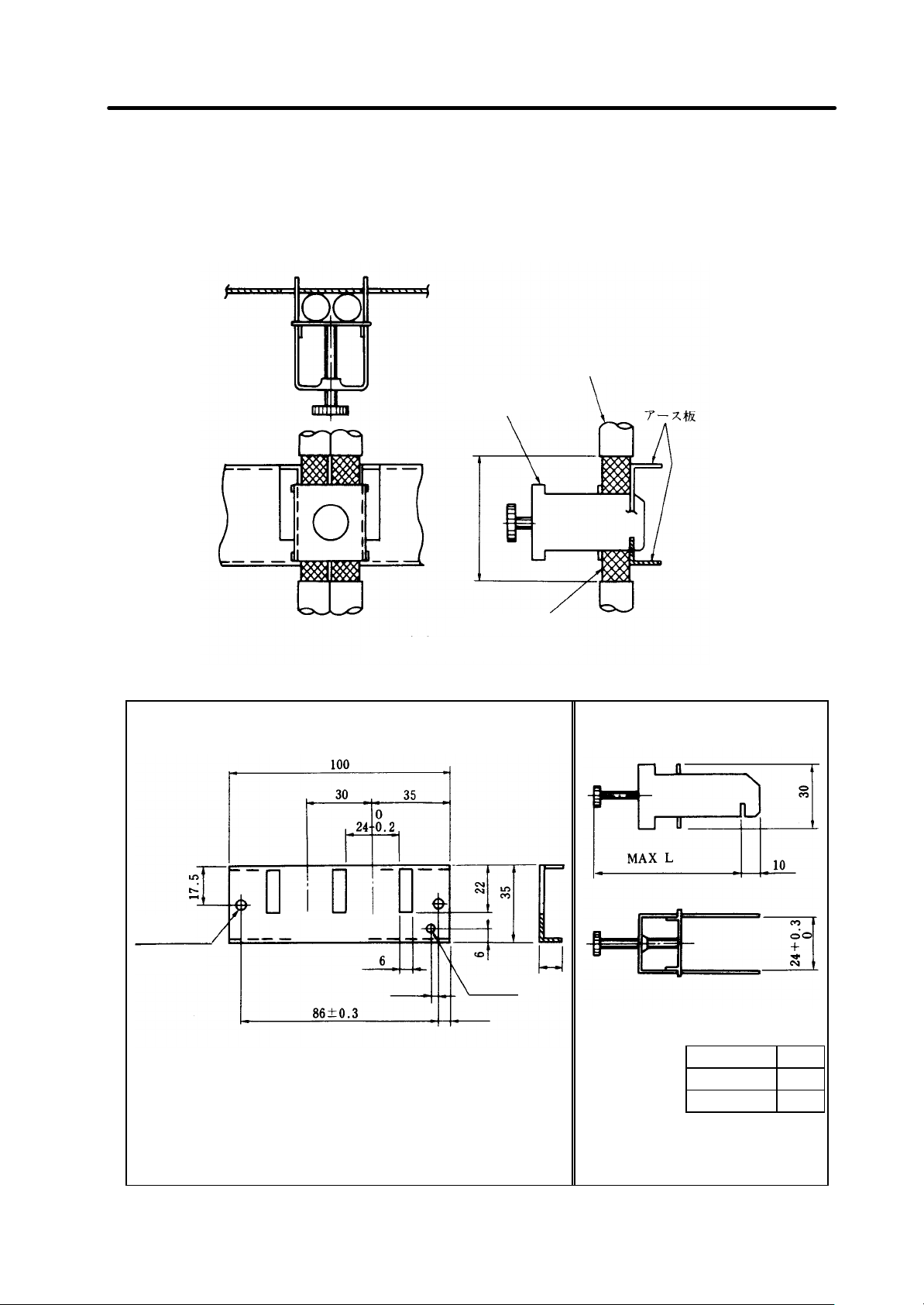
Grounding plate
(D)
Cable
Shield outer sheath
M4 screw
3 7 11
5. Drive Section Connector and Cable Specifications
5.2.11 Cable clamp
Mount the grounding plate near the servo drive unit, peel the cable sheath, and press the peeled shield
cable to the grounding plate using the cable clamp. If the cable is thin, clamp several cables.
Cable clamp
(Metal fitting A, B)
Clamp section drawing
The grounding plate D and cable clamps A and B can be supplied by Mitsubishi.
Grounding plate (D) outline drawing
2-ø5 hole
installation hole
∗
Cable clamp outline drawing
• The grounding wire should be connected between the
grounding plate and the cabinet grounding plate.
• Two metal fittings A can be used.
∗ Screw hole for wiring to cabinet grounding plate
L
Metal fitting A 70
Metal fitting B 45
I - 37
Page 66

connection
Arranged
Arranged
×2
×2
5. Drive Section Connector and Cable Specifications
5.2.12 Spindle control circuit cable list
No. Application
Motor speed
detection signal
(1)
Motor temperature
switch signal
Magnetic sensor
(2)
Orientation
detection signal
Encoder
(3)
Orientation
detection signal
C-axis encoder
(4)
C-axis detection
signal
(OSE90K+1024)
C-axis built-in
encoder
(5)
C-axis detection
signal
(MBE90K)
C-axis built-in
encoder
(6)
C-axis detection
signal
(MHE90K)
C-axis encoder
C-axis detection
signal +
(7)
orientation
detection signal
(OSE90K+1024)
Drive unit
side
connector
CN5
CN6
CN6
CN7
CN7
CN7
CN6 + CN7
Cable
name
CNP5
cable
CNP6M
cable
CNP6A
cable
CNP7A
cable
CNP7B
cable
CNP7H
cable
CNP67A
cable
Connected device
Parts name Parts name
Maker
Applicable cable finished state
by
Twisted pair batch shield cable
Spindle drive unit
0.2SQ
(Shell)
Maximum diameter 11mm
10320-52F0-008
(Plug)
10120-3000VE
Semi ordered part
Sumitomo 3M
Spindle drive unit
(Shell)
10320-52F0-008
Twisted pair batch shield cable
0.2SQ
Maximum diameter 11mm
(Plug)
Connected device
Motor (connector)
Motor (lead wire
terminal)
(Connector)
AMP-350720-1
(Pin)
AMP-350689-1
Japan Amplifier
Magnetic sensor
drive unit
TRC116-12A0-7F
10.5
10120-3000VE
Sumitomo 3M
Spindle drive unit
(Shell)
10320-52F0-008
(Plug)
Semi ordered part
Twisted pair batch shield cable
0.2SQ
Maximum diameter 11mm
Tajimi Musen
Encoder
(RFH-1024-)
MS3106A20-29S
10120-3000VE
Sumitomo 3M
Spindle drive unit
(Shell)
10320-52F0-008
(Plug)
Semi ordered part
Twisted pair batch shield cable
0.2SQ
Maximum diameter 11mm
Encoder
(OSE90K+1024)
MS3106A20-29S
10120-3000VE
Sumitomo 3M
Spindle drive unit
(Shell)
10320-52F0-008
(Plug)
10120-3000VE
Sumitomo 3M
Spindle drive unit
(Shell)
10320-52F0-008
(Plug)
10120-3000VE
Sumitomo 3M
Spindle drive unit
(Shell)
10320-52F0-008
(Plug)
10120-3000VE
Semi ordered part
Twisted pair batch shield cable
0.2SQ
Maximum diameter 11mm
Semi ordered part
Twisted pair batch shield cable
0.2SQ
Maximum diameter 7mm
No ordered part
Twisted pair batch shield cable
0.2SQ
Maximum diameter 11mm
Semi ordered part
Encoder
(MBE90K)
(Housing)
69176-020
(Pin)
48235-000
Encoder
(MHE90K)
(Housing)
JAC-15P
(Pin)
J-SP1140
Japan Solderless
Encoder
(OSE90K+1024)
MS3106A20-29S
Sumitomo 3M
Maker
DDK
DDK
DuPont
DDK
by
Enclosed with motor
Enclosed with magnet-
ic sensor drive unit
Enclosed with encoder Enclosed with encoder
Enclosed with encoder
Enclosed with encoder
Enclosed with encoder
I - 38
Page 67

connection
Arranged
Arranged
signal + NC speed
signal + NC speed
signal + NC speed
Enclosed with
encoder
No. Application
C-axis encoder
C-axis detection
(8)
indication signal
(OSE90K+1024)
C-axis built-in
encoder
C-axis detection
(9)
indication signal
(MBE90K)
C-axis built-in
encoder
(10
C-axis detection
)
indication signal
(MHE90K)
C-axis built-in
encoder
Motor speed
(11
detection signal
)
+ motor
temperature
switch signal
(MHE90K)
(12
Speed detection
)
signal
5. Drive Section Connector and Cable Specifications
Drive unit
side
connector
CN7 +
CES11
CN7 +
CES11
CN7 +
CES11
CN5
CN8
Cable
name
CNP71A
cable
CNP71B
cable
CNP71H
cable
CNP5H
cable
CNP8
cable
Connected device
Parts name Parts name
Maker
Spindle drive unit
(Shell)
10320-52F0-008
(Plug)
10120-3000VE
Sumitomo 3M
CNC
(Connector)
CDA-15P
(Contact)
CD-PC-111
(Case) HDA-CTF
Hirose
Spindle drive unit
(Shell)
10320-52F0-008
(Plug)
10120-3000VE
Sumitomo 3M
CNC
(Connector)
CDA-15P
(Contact)
CD-PC-111
(Case) HDA-CTF
Hirose
Spindle drive unit
(Shell)
10320-52F0-008
(Plug)
10120-3000VE
Sumitomo 3M Japan Solderless
CNC
(Connector)
CDA-15P
(Contact)
CD-PC-111
(Case) HDA-CTF
Hirose
Spindle drive unit
(Shell)
10320-52F0-008
(Plug)
10120-3000VE
Sumitomo 3M
Spindle drive unit
(Shell)
10320-52F0-008
(Plug)
10120-3000VE
Applicable cable finished state
by
Twisted pair batch shield cable
0.2SQ
Maximum diameter 11mm
Semi ordered part
Twisted pair batch shield cable
0.2SQ
Maximum diameter 11mm
Semi ordered part
Twisted pair batch shield cable
0.2SQ
Maximum diameter 7mm
No ordered part
Twisted pair batch shield cable
0.2SQ
Maximum diameter 7mm
No ordered part
Twisted pair batch shield cable
0.2SQ
Maximum diameter 11mm
Connected device
Maker
Encoder
(OSE90K+1024)
MS3106A20-29S
DDK
Encoder (MBE90K)
(Housing)
69176-020
(Pin)
48235-000
DuPont
00
Encoder (MHE90K)
(Housing)
JAC -15P
(Pin)
J-SP1140
(Housing)
JAC -15P
(Pin)
J-SP1140
Japan Solderless
Encoder (MHE90K)
(Housing)
JEC -9P
(Pin)
J-SP1140
Japan Solderless
NC control unit
(QX522 card CES11)
(Connector)
CDA-15P
(Contact)
CD-PC-111
(Case) HDA-CTF
by
Enclosed with encoder
Enclosed with encoder
Enclosed with encoder
Semi ordered part
Sumitomo 3M
(Note) When the spindle has
two axes, a cable must be
Hirose
added as shown in the
dotted line.
I - 39
Page 68

5. Drive Section Connector and Cable Specifications
(Note 1) The connector shell on the spindle drive unit is the 3M "10320-52F0-008", but this is a shell with
a one-touch locking mechanism that does not require screw locking.
When ordering the cables from Mitsubishi, the shell "10320-52F0-008" with this one-touch
locking mechanism will be used.
However, if the cable is to be manufactured by the user, the shell "10320-52A0-008" (3M) with the
screw lock mechanism can be used instead of the above shell.
(Note 2) Each cable length must be 30m or less.
The cable for the C-axis built-in encoder MHE90K must be 10m or less.
I - 40
Page 69

Cable name
Connector type
Axis No. (Axis 1 to 8)
System No.
Connection connector No.
Drive unit connector
Detector connector
Pin No.
Pin No.
Blue Green White Purple White Yellow Brown Red Brown Black
2
E
5. Drive Section Connector and Cable Specifications
E: E-type (crimp terminal on lead end)
2: 2-type (designated connector)
1 to 8: Axis 1 to 8
None : 1-axis system
2 : 2-axis system
P : PLC axis
Qty/type
1
1
1
-type
-type
(Note) Connect the shield of the cable securely to the connector shell.
Length L (L ≤ 30m)
1
8
2-type
1
E-type
Model
10320-52F0-008
CON
Abbr.
Part name
1
10120-3000VE
CON
1
F-DPEVSB TS-91026
(BANDO ELECTRIC WIRE)
SEN
350720-1
350689-1
CON
CON
(1) CNP5 cable
Part No.
000
Connector (shell)
101
Connector (plug)
102
103
Cable
Connector (housing)
Connector (pin)
104
105
106
I - 41
Page 70

Connector type
Axis No. (Axis 1 to 8)
System No.
Magnetic sensor
Connection connector No.
1 1
1 1
1
Drive unit connector
Detector connector
Pin No.
Green White Blue Brown Purple Brown
Pin No.
2
E
(Note)
5. Drive Section Connector and Cable Specifications
E: E-type (crimp terminal on lead end)
2: 2-type (designated connector)
1 to 8: Axis 1 to 8
None : 1-axis system
2 : 2-axis system
P : PLC axis
Cable name
Qty/type
-type
signal
-type
Connect the shield of the cable securely to the connector shell.
1
1
Length L (L ≤ 30m)
2-type
E-type
Model
10320-52F0-008
10120-3000VE
F-DPEVSB TS-91026
(BANDO ELECTRIC WIRE)
TRC116-12A10-7F10.5
Abbr.
Part name
CON CON
Connector (shell) Connector (plug)
SEN
Cable
CON
Connector
000
101
102
103
104
105
106
107
(2) CNP6M cable
Part No.
108
I - 42
Page 71

Cable name
Connector type
Axis No. (Axis 1 to 8)
System No.
Encoder signal (1024P
Connection connector No.
1 1
1 1
1 1
(
angle)
(
Straight
)
2
E
3
Detector connector
Pin No.
Drive unit connector
Pin No.
Green White Purple White Yellow Brown Red Brown
Brown Purple Blue
Black
(Note)
5. Drive Section Connector and Cable Specifications
E: E-type (crimp terminal on lead end)
2: 2-type (cannon plug straight type)
3: 3-type (cannon plug L type)
1 to 8: Axis 1 to 8
3-type
Qty/type
) RFH-1024-
None : 1-axis system
2 : 2-axis system
P : PLC axis
1
1
-type
-type
Key way
-type
position
Connect the shield of the cable securely to the connector shell.
1
1
1
Length L (L ≤ 30m)
1
2-type
1
E -type
Model
10320-52F0-008
10120-3000VE
F-DPEVSB TS-91026
(BANDO ELECTRIC WIRE)
MS3108B20-29S
MS3057-12A
MS3106B20-29S
Abbr.
CON CON
SEN
CON
CON
CON
Part name
Connector (shell)
Connector (plug)
Cable
Cannon connector
Connector clamp
Cannon connector
000
101
102
103
104
105
106
107
(3) CNP6A cable
108
Part No.
I - 43
Page 72

Cable name
Connector type
Axis No. (Axis 1 to 8)
System No.
Shaft type encoder signal (90,000P) OSE90K+1024
Connection connector No.
1 1
1 1
1 1
(
Straight
)
Key way
position
Pin No.
Pin No.
Green White Purple White Yellow Brown Red Brown
Brown Purple Blue Black
(Note)
5. Drive Section Connector and Cable Specifications
E: E-type (crimp terminal on lead end)
2: 2-type (cannon plug straight type)
3: 3-type (cannon plug L type)
1 to 8: Axis 1 to 8
3-type
Qty/type
None : 1-axis system
2 : 2-axis system
P : PLC axis
1
1
2-type
3-type
E-type
Connect the shield of the cable securely to the connector shell.
1
1
1
1
Length L (L ≤ 30m)
2-type
1
E-type
Model
Detector connector
10320-52F0-008
10120-3000VE
F-DPEVSB TS-91026
(BANDO ELECTRIC WIRE)
MS3108B20-29S
MS3057-12A
MS3106B20-29S
Abbr.
CON CON
SEN
CON
CON
CON
Part name
Connector (shell)
Connector (plug)
Cable
Cannon connector
(angle)
Connector clamp
Cannon connector
Drive unit connector
000
101
Part No.
(4) CNP7A cable
102
103
104
105
106
107
108
I - 44
Page 73

Cable name
Connector type
Axis No. (Axis 1 to 8)
System No.
Built-in type encoder signal (90,000P) MBE90K
Connection connector No.
1 1
13
1 1
1
D
Pin No.
Drive unit connector
Pin No.
Green White Purple White Yellow Brown Red Brown
Brown Purple Blue Black
5. Drive Section Connector and Cable Specifications
E: E-type (crimp terminal on lead end)
Qty/type
2: 2-type (connection connector)
1 to 8: Axis 1 to 8
None : 1-axis system
2 : 2-axis system
P : PLC axis
1
1
2-type
E-type
(Note) Connect the shield of the cable securely to the connector shell.
Length L (L ≤ 30m)
2-type
E-type
Model
etector connector
10320-52F0-008
10120-3000VE
F-DPEVSB TS-91026
(BANDO ELECTRIC WIRE)
69176-D20
48235-000
Abbr.
Part name
CON CON
Connector (shell)
Connector (plug)
SEN
Cable
CON CON
Connector (housing)
Connector (pin)
000
(5) CNP7B cable
Part No.
101
102
103
104
105
106
107
108
I - 45
Page 74
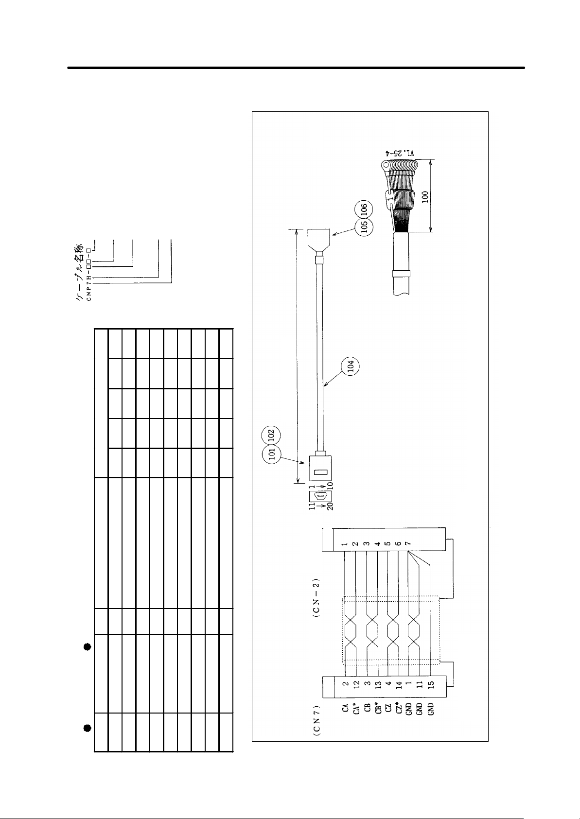
Cable name
Connector type
Axis No. (Axis 1 to 8)
System No.
Built-in type encoder signal (90,000P) MHE90K
Connection connector No.
1 1
1 1 7
1 1
1
2
E
≤
Pin No.
Drive unit connector
Pin No.
5. Drive Section Connector and Cable Specifications
E: E-type (crimp terminal on lead end)
2: 2-type (designated connector)
1 to 8: Axis 1 to 8
None : 1-axis system
2 : 2-axis system
P : PLC axis
Qty/type
-type
10m)
Length L (L
-type
2-type
E-type
(Note 1) This cable is not available from Mitsubishi, and must be manufactured by the user.
(Note 2) Connect the shield of the cable securely to the connector shell.
Model
Abbr.
Part name
10320-52F0-008
10120-3000VE
CON CON
Connector (shell)
Connector (plug)
JAC-15P
SEN
CON CON
Cable
Connector (housing)
J-SP1140
Connector (pin)
Detector
connector
(6) CNP7H cable
000
Part No.
101
102
103
104
105
106
107
108
I - 46
Page 75

Connector type
Axis No. (Axis 1 to 8)
System No.
Shaft type encoder signal (90,000P+1024P) OSE90K+1024
Connection connector No.
Cable name
(
BANDO ELECTRIC WIRE
)
(
angle
)
(
Straight
)
Detector connector
Pin No.
Drive unit connector
Pin No.
Green White Purple White Yellow Brown Red Brown
Brown Purple Black
Pin No.
Drive unit connector
Blue
Red White Blue Brown Green Brown
5. Drive Section Connector and Cable Specifications
2-type
E: E-type (crimp terminal on lead end)
2: 2-type (cannon plug straight type)
3: 3-type (cannon plug L type)
1 to 8: Axis 1 to 8
None : 1-axis system
2 : 2-axis system
P : PLC axis
2
2
1
1
1
Length L (L ≤ 30m)
3-type
Key way
E-type
position
(Note) Connect the shield of the cable securely to the connector shell.
3-type
Qty/type
2
2-type
2
E-type
Model
10320-52F0-008
CON
Abbr.
Part name
2
2
10120-3000VE
CON
1
1
F-DPEVSB TS-91026
SEN
1
MS3108B20-29S
MS3057-12A
CON
CON
1
MS3106B20-29S
CON
Connector (shell)
Connector (plug)
000
101
(7) CNP67A cable
Part No.
102
103
Cable
Cannon connector
Connector clamp
104
105
106
Cannon connector
107
108
I - 47
Page 76

Connector type
Axis No. (Axis 1 to 8)
System No.
Shaft type encoder signal (90,000P+1024P) OSE90K+1024
Connection connector No.
Cable name
(
BANDO ELECTRIC WIRE
)
(
Straight
)
(
angle
)
2
E
3
Key way
position
Pin No.
Drive unit connector
Pin No.
NC connector
Green White Purple White Yellow Brown Red Brown
Purple
Brown B
lack
Blue
Red White Blue Brown Green Brown
(Note)
5. Drive Section Connector and Cable Specifications
E: E-type (crimp terminal on lead end)
2: 2-type (cannon plug straight type)
3: 3-type (cannon plug L type)
1 to 8: Axis 1 to 8
None : 1-axis system
2 : 2-axis system
P : PLC axis
1
1
3-type
Qty/type
1
1
1
2
2-type
1
1
2
-type
-type
-type
Connect the shield of the cable securely to the connector shell.
1
1
1
6
1
1
1
6
1
1
6
1
Length L1 (L1 ≤ 30m)
Length L2 (L2 ≤ 30m)
Model
Abbr.
Part name
(8) CNP71A cable
Part No.
E-type
10320-52F0-008
10120-3000VE
CON
CON
Connector (shell)
Connector (plug)
000
101
102
MS3106B20-29S
F-DPEVSB TS-91026
MS3108B20-29S
SEN
CON
Cannon connector
103
CON
Cable
Cannon connector
104
105
MS3057-12A
CDA-15P
CD-PC-111
HDA-CTF
CON
CON
CON
CON
Connector clamp
Connector
Contact
Case
106
107
108
109
Detector connector
Pin No.
I - 48
Page 77

Cable name
(
BANDO ELECTRIC WIRE
)
≤
NC connector
Detector connector
Pin No.
Drive unit connector
Pin No.
Green White Purple White Yellow Brown Red Brown
Brown Purple Black
Pin No.
Blue
Red White Blue
Brown Green Brown
(Note)
5. Drive Section Connector and Cable Specifications
E: E-type (crimp terminal on lead end)
2: 2-type (designated connector)
1 to 8: Axis 1 to 8
None : 1-axis system
2 : 2-axis system
Connector type
Axis No. (Axis 1 to 8)
P : PLC axis
System No.
Built-in type encoder signal (90,000P+1024P) MBE90K
Connection connector No.
Qty/type
1
2-type
1
1
1
2
2
2-type
E-type
30m)
Connect the shield of the cable securely to the connector shell.
Length L1 (L1 ≤ 30m)
1
1
6
19
1
1
6
1
Length L2 (L2
Model
Abbr.
Part name
(9) CNP71B cable
Part No.
E-type
10320-52F0-008
10120-3000VE
CON
CON
Connector (shell)
Connector (plug)
000
101
102
F-DPEVSB TS-91026
69176-020
48235-000
SEN
CON
CON
Cable
Connector (housing)
Connector (pin)
103
104
105
106
CDA-15P
CD-PC-111
HDA-CTF
CON
CON
CON
Connector
Contact
Case
107
108
109
I - 49
Page 78

Connector type
Axis No. (Axis 1 to 8)
System No.
Built-in type encoder signal (90,000P+1024P) MHE90K
Connection connector No.
Cable name
(
BANDO ELECTRIC WIRE
)
2
E
≤
(Note 1)
(Note 2)
Detector connector
Pin No.
Pin No.
Pin No.
NC connector
Detector connector
Pin No.
5. Drive Section Connector and Cable Specifications
E: E-type (crimp terminal on lead end)
2: 2-type (designated connector)
1 to 8: Axis 1 to 8
None : 1-axis system
2 : 2-axis system
P : PLC axis
Qty/type
1
1
2
2-type
1
1
2
-type
-type
10m)
Length L2 (L2
Length L1 (L1 ≤ 10m)
2
1
6
13
1
This cable is not available from Mitsubishi, and must be manufactured by the user.
Connect the shield of the cable securely to the connector shell.
1
6
1
Model
Abbr.
Part name
(10) CNP71H cable
Part No.
E-type
10320-52F0-008
10120-3000VE
CON
CON
Connector (shell)
Connector (plug)
000
101
102
F-DPEVSB TS-91026
JAC-15P
J-SP1140
SEN
CON
CON
Cable
Connector (housing)
Connector (pin)
103
104
105
106
CDA-15P
CD-PC-111
HDA-CTF
CON
CON
CON
Connector
Contact
Case
107
108
109
Drive unit connector
I - 50
Page 79

Connector type
Axis No. (Axis 1 to 8)
System No.
Built-in type encoder signal (180 wave
Connection connector No.
Cable name
(
BANDO ELECTRIC WIRE
)
2
(Note 1)
(Note 2)
Pin No.
(CN
Detector connector
Pin No.
(CN5)
Drive unit connector
5. Drive Section Connector and Cable Specifications
) MHE90K
E: E-type (crimp terminal on lead end)
2: 2-type (designated connector)
1 to 8: Axis 1 to 8
None : 1-axis system
2 : 2-axis system
P : PLC axis
Qty/type
1
1
1
-type
1
7
Length 1 (L ≤ 10m)
E-type
2-type
1
E-type
Model
10320-52F0-008
CON
Abbr.
Part name
Connector (shell)
1
10120-3000VE
CON
Connector (plug)
1
F-DPEVSB TS-91026
SEN
Cable
JEC-9P
J-SP1140
CON
CON
Connector (housing)
Connector (pin)
This cable is not available from Mitsubishi, and must be manufactured by the user.
Connect the shield of the cable securely to the connector shell.
-6)
(11) CNP5H cable
000
Part No.
101
102
103
104
105
106
I - 51
Page 80

Cable name
Connection connector No.
14 1
(
BANDO ELECTRIC WIRE
)
Pin No.
Pin No.
Pin No.
Drive unit connector
Cable clamp
(Note 1)
(Note
(Note 3)
NC connector
5. Drive Section Connector and Cable Specifications
(Note) When using the 2-axis spindle, the required quantity of part
No. 101 to 104 on the left will be two.
Qty/type
1 1
Model
1
1
Length L (L ≤ 50m)
This cable is not available from Mitsubishi, and must be manufactured by the user.
Connect the shield of the cable securely to the connector shell.
2) The area enclosed by broken line indicates the 2-axis spindle connection.
(12) CNP8 cable
Abbr.
Part name
000
Part No.
10320-52F0-008
10120-3000VE
CON CON
Connector (shell) Connector (plug)
101
102
F-DPEVSB TS-91026
CDA-15P
CD-PC-111
HDA-CTF
SEN
CON CON CON
Cable
Connector
Contact
Case
103
104
105
106
107
Cable clamp
I - 52
Page 81

5. Drive Section Connector and Cable Specifications
5.2.13 Cable assembly procedure (Excluding SH21 cable)
(1) Non-shield shell assembly procedure I
One-touch locking type
(a)
Shield wire
Peel the outer sheath so that the shield wires are
exposed.
(b)
(c)
(d)
Copper tape
Folded shield wire
Wrap copper tape or vinyl tape around part of the
shield wire section.
Fold the shield wire over the wrapped copper tape or
vinyl tape.
Cut off any excess sheath.
(e)
Folded shield wire
Cable clamp with
grounding plate
After connecting the connector and cable, mount the
cable clamp approx. 1 to 2mm from the cable end,
and tighten the screw until the cable clamp screw
section face contacts closely.
(Note) Adjust the No. of copper tape windings in
step (b) so that the shield wire and clamp
contact without looseness and so that the
clamp's screw section face is closely
contacted.
I - 53
Page 82

5. Drive Section Connector and Cable Specifications
(f)
Store a connector and latch at the respective
positions on one end of the shell.
Latch
(The male of the shell is same shape as female's, so
store on either side.)
(Note) Make sure that the cable does not rise up or
exceed the shell's inner wall to prevent
breakage of the cable.
(g)
(h)
Set the other shell and tighten with a screw.
(Note) Recommended screw tightening torque:
3kgf·cm
Completion
Confirmation items :
• There is no clearance on the shell engaging
face.
• The latch can be correctly opened and closed
when moved with a finger.
I - 54
Page 83

5. Drive Section Connector and Cable Specifications
(2) Non-shield shell assembly procedure II
Jack screw (screw locking) type
(a)
Shield wire
Peel the outer sheath so that the shield wires are
exposed.
(b)
(c)
(d)
Wrap copper tape or vinyl tape around part of the
shield wire section.
Copper tape
Fold the shield wire over the wrapped copper tape or
vinyl tape.
Folded shield wire
Cut off any excess sheath.
(e)
Folded shield wire
Cable clamp with
grounding plate
After connecting the connector and cable, mount the
cable clamp approx. 1 to 2mm from the cable end,
and tighten the screw until the cable clamp screw
section face contacts closely.
(Note) Adjust the No. of copper tape windings in
step (b) so that the shield wire and clamp
contact without looseness and so that the
clamp's screw section face is closely
contacted.
I - 55
Page 84

5. Drive Section Connector and Cable Specifications
(f)
Jack screw
Store a connector and jack screw at the respective
positions on one end of the shell.
(The male of the shell is same shape as female's, so
store on either side.)
(Note) Make sure that the cable does not rise up or
exceed the shell's inner wall to prevent
breakage of the cable.
(g)
(h)
Set the other shell and tighten with a screw.
(Note) Recommended screw tightening torque:
3kgf·cm
Completion
Confirmation items :
• There is no clearance on the shell engaging
face.
I - 56
Page 85

6. Outline Drawing
6. Outline Drawing .............................................................................................................. I-58
6.1 Panel installation structure ..................................................................................... I-58
6.2 Power supply unit ................................................................................................... I-59
6.3 1-axis servo drive unit/2-axis servo drive unit/spindle servo drive unit .................. I-60
6.4 Battery unit.............................................................................................................. I-61
6.5 AC reactor............................................................................................................... I-62
6.6 Dynamic brake unit................................................................................................. I-63
6.7 Contactor ................................................................................................................ I-63
6.8 Circuit Breaker (CB)................................................................................................ I-63
I - 57
Page 86

box
box
Power supply unit
Fin and fan
Fin and fan
5 screw
6. Outline Drawing
6.1 Panel installation structure
(1) Unit outline
[Power supply unit] [Spindle drive, servo drive unit]
6. Outline Dra wing
Maintenance
area
(Note)
Outside box Outside boxInside
Maintenance
area
Required wind
passage space
(Side)
The type A0 unit noted in section "2.Drive Section System Configuration (2)
and (3)" do not have the fin and fan section.
Inside
Spindle/servo
drive unit
(Side)
Required wind
passage space
(2) Panel installation hole work drawing
Prepare a square hole to match the unit width.
(Note 1) The A0 type unit described in section "2. Drive Section System Configuration (2) and (3)"
does not require to make a square hole.
(Note 2) Install packing around the square hole to provide a seal.
2-5 screw
Square hole
Square hole
(Installation)
Unit width size
(Front)
Square hole
(Installation)
2-5 screw
(Installation)
Unit width size W 60 90 120 150
b 360 360 360 360
c 52 82 112 142
d 342 342 342 342
(Unit: mm)
4-
I - 58
Page 87

60 15
6. Outline Dra wing
6.2 Power supply unit
∗1 The position of the CV-37 to 185 CN4 and CN9 is approx. 39mm lower than the MDS-B-CV Series. No
changes have been made to the CV -220 to 370.
∗2 The position of the ground has been moved from the terminal block to the unit installation base.
The fin section includes 15mm required for the wind passage space.
C1-CV-37/55/75 C1-CV-110 C1-CV-150/185
フィン
フィン
Fin
2-ø6 hole
C1-CV-220/260/300/370
2-ø6
hole
2-ø6
hole
Terminal cover
60
15
1 5
6 0 15
60
275
Wiring
space
275
Fin
Terminal cover
4-ø6 hole
Wiring
spac e
275
275
6 0 15
I - 59
Page 88

15
Fin Terminal cover
60 15
6. Outline Dra wing
6.3 1-axis servo drive unit/2-axis servo drive unit/spindle servo drive unit
The fin section includes 15mm required for the wind passage.
C1-V1-01/03/05/ C1-V1-45/70S C1-V1-70/90
10/20/35/45S V2-3535/ V2-4545/7035/7045
V2-0101 to 4520/4535/ SP-150/185
3520S 7070S
SP-04/075/15/ SP-55/75/
22/37 110/150S
Fin
C1-V2-7070
SP-220
2-ø6 hole
∗ Note that C-V 1-01 to 10 has no fin.
Note that SP -04/075/15 and V1-01 to 10 have no fins.
2-ø6
hole
2-ø6
ho le
Terminal cover
6 0 15
60
Wiring
space
275
2 7 5
フィン
4-ø6
4-ø6
hole
hole
Wiring
Wiring
space
space
Terminal cov er
6 0 15
275
275
I - 60
Page 89

4 6 8
6. Outline Drawing
The fin section includes 12mm required for the wind passage space.
C1-V1-110/150
SP-260/300
Terminal cover
フィン
Fin
4-ø6 hole
6.4 Battery unit
ø6 Use a M5 screw for installation
Wiring
space
6 3 12
27 5
MDS-A-BT-2
Battery unit outline drawing
I - 61
Page 90

6-screw
4-8×15 slot
(
with ground mark)
Terminal cover
Y
6- M6 screw
(
with ground mark)
Terminal cover
4-8×15 slot
6.5 AC reactor
AC reactor outline drawing
(1) For 30kW or less
FG connection
position
PE connection position
6. Outline Drawing
ACL model
B-AL-7.5K C1-CV-37, C1-CV-55, C1-CV-75 82 130 3.6kg
B-AL-11K C1-CV-110 75 130 3.0kg
B-AL-18.5K C1-CV-150, C1-CV-185 105 140 5.2kg
B-AL-30K
Corresponding power supply unit Ys
C1-CV-220, C1-CV-260,
C1-CV-300
110 150 6.0kg
AC reactor outline
drawing
(2) 37kW
FG connection
position
PE connection position
Weight Screw
M5
M6
ACL model Corresponding power supply unit Ys Y Weight
B-AL-37K C1-CV-370 110 150 10.0kg
I - 62
Page 91

153±0.4
6 35
6. Outline Drawing
(Note 1) This AC reactor has a PE (protection grounding) terminal for electric shock prevention and an FG
(function grounding) terminal for noise measures. Observe the following cautions for treating each
terminal.
(1) PE terminal ( )
(a) When AC reactor installation side is PE
Install the AC reactor unit with screws (bolts) in all four installation holes.
Always insert a loosening-prevention washer and spring washer in the screw (bolt) used
for the mark installation hole, and tighten the screw.
(b) When AC reactor installation side is not PE
Install the AC reactor unit with screws (bolts) in all four installation holes.
Always insert a loosening-prevention washer and spring washer and tighten the screw
together with the grounding wire (PE) crimp terminal at the mark installation hole.
The grounding wire used is the same type as the grounding wire connected to the power
supply unit.
(2) FG terminal (FG)
Screw the function grounding wire crimp terminal at the terminal marked as "FG" on the top of
the AC reactor (terminal block).
(With this treatment, the built-in filter's grounding will be directly connected to the grounding,
and the noise withstand level will be improved.)
∗ Function grounding wire: This is a grounding wire not used for protection grounding. Thus,
do not use a green/yellow spiral wire.
(Note 2) The dimensions of the terminal cover are as
shown on the right.
When separately manufacturing a cover,
refer to the dimensions on the right.
130±0.7
165±0.7
2-ø4.6
6.6 Dynamic brake unit
Model A B C D E F
MDS-B-DB
U-150
200 190 140 20 5 200 193.8 2kg V1-110/150
6.7 Contactor
Refer to the section "8.6 Selection of AC reactor, contactor and CB".
6.8 Circuit Breaker (CB)
Refer to the section "8.6 Selection of AC reactor, contactor and CB".
I - 63
G Weight
(Unit: mm)
Applicable
servo
drive unit
Page 92

Page 93

7. Heating Value
7. Heating Value................................................................................................................... I-66
I - 65
Page 94

Velocity 2m/s or more
27
21 27 37 53 25 30 37 50 56 74 96 34 38 0 0 0 0 66
6580
212325262933354046
4255
40
49
79
3040
2831
486265
48000
76
38
46
52
62
78
96
38 41 43 46 52 62 78 96 37 41 42 45 51 52 57 64 70 77 90 44 48
0
0 0
000
7. Heating Value
7. Heating Value
(1) Power supply unit (2) Spindle drive unit (3) 1-axis servo drive unit
Model
CV- 37
CV- 55
CV- 75
CV-110
CV-150
CV-185
CV-220
CV-260
CV-300
CV-370
Total heating value (W)
55
125
155
195
210
260
320
400
Inside
unit (W)
54
Outside
unit (W)
34
99
126
162
175
220
274
346
Total heat-
Model
ing value (W)
SP- 04
SP-075
SP- 15
SP- 22
SP- 37
SP- 55108
SP- 75 137
SP-110 181
SP-150235
SP-185342
SP-220
SP-260
SP-300
SP-150S
30
69
366
483
620
235
Inside
unit (W)
49
26
35
41
80
98
Outside
unit (W)
42
51
102
140
187
280
301
403
522
140
Total heat-
Model
ing value (W)
V1- 01
V1- 03
V1- 05
V1- 10
V1- 20
V1- 35 132
V1- 45 185
V1- 70 284
V1- 90 331
V1-110 465
V1-150 641
V1-45S 158
V1-70S 189
21
37
53
91
Inside
unit (W)
Outside
unit (W)
102
148
234
275
392
545
124
151
(4) 2-axis servo drive unit
Model
V2-0101
V2-0301
V2-0303
V2-0501
V2-0503
V2-0505
V2-1005
V2-1010
V2-2010 155
V2-2020 178
V2-3510 190
V2-3520 213
V2-3535 260
V2-4520 266
V2-4535 307
V2-4545 359
V2-7035 406
V2-7045 459
V2-7070 558
V2-3510S 190
V2-3520S 213
V2-7070S 365
Total heating value (W)
41
43
Inside
unit (W)
65
Outside
unit (W)
117
137
148
168
209
214
249
295
336
382
468
146
165
300
0
0
(Note 1) The heating value for the spindle drive unit is for during continuous rated output and for the
servo drive unit is for during the rated output when operating in the high-gain mode.
If the servo drive unit is operated in the standard mode, the heating value will be less than the B
Series heating value. However, the new design is not supposed to operate in the standard
mode, so the data has been omitted.
(Note 2) The total heat ing value for the power supply includes the AC reactor heating value.
(Note 3) For the total heating value for the unit, add the heating value for the corresponding unit above
that is mounted on the actual machine.
Example) When mounted unit is CV-185, SP-110, V1-35, V2-2020
Total unit heating value (W) = 195 + 181 + 132 + 178 = 686 (W)
(Note 4) When designing the box for the fully closed installation, consider the actual load ratio as the
heating value inside the servo drive unit, and use the following equation.
Heating value inside servo drive unit (considering load ratio)
= heating value inside unit obtained with the above table × 0.5
(However, this excludes the power supply unit and spindle drive unit.)
If it is clear that the load ratio is larger than 0.5, substitute that load ratio for "× 0.5" in the above
equation.
Example If the mounted servo drive unit is V1-35:
Heating value inside unit (during rated output)
= 30 (W)
Thus,
Heating value inside unit (considering load ratio)
= 30 × 0.5 = 15 (W)
(Note 5) Due to the structure, heat will tend to accumulate that
the top of each unit. Thus, install a fan in the distribution
box to mix the heat at the top of each unit.
(Inside box)
Servo drive
Servo drive
Servo drive
Spindle drive
Power supply
I - 66
Page 95

8. Selection of Capacity
8. Selection of Capacity....................................................................................................... I-68
8.1 Selection of the power supply unit capacity............................................................. I-68
8.1.1 Selection with rated capacity (continuous rated capacity).............................. I-68
8.1.2 Selection with maximum momentary rated capacity....................................... I-70
8.1.3 Selection data................................................................................................. I-70
8.1.4 Selection example........................................................................................... I-71
8.2 Selection of leakage breaker................................................................................... I-72
8.3 Noise filter................................................................................................................ I-73
8.4 Selection of power supply capacity ........................................................................ I-75
8.5 Selection of wire size ............................................................................................. I-76
8.6 Selection of AC reactor, contactor and CB ............................................................. I-81
I - 67
Page 96

8. Selection of Capacity
8. Selection of Capacity
8.1 Selection of the power supply unit capacity
In addition to "selection conditions following the rated capacity (continuous rated capacity)" with the
conventional method, select the power supply unit so that "selection conditions under the maximum
momentary rated capacity" are simultaneously satisfied.
Conventionally, the power supply unit capacity was selected based on the total rated capacity of the
motors connected to the power supply unit.
However, as the machines become faster and the increased torqu e occur during acceleration/
deceleration following that the acceleration/deceleration time constant become shorter, stricter
working conditions have been applied to the acceleration/deceleration for the power supply unit. Thus,
selection conditions have been set for the maximum momentary rated capacity to prevent use
exceeding the momentary power processing capacity.
8.1.1 Selection with rated capacity (continuous rated capacity)
(Note) In this section, "continuous rated capacity" will be indicated as "rated capacity".
(1) When using 1-axis servomotor
Power supply unit rated capacity
> Σ (Spindle motor output) + (Servomotor output)
....... 1)
(2) When using 2 or more axes servomotor
Power supply unit rated capacity
> Σ (Spindle motor output) + 0.7 × Σ (Servomotor output)
....... 2)
(Note 1) Σ (Spindle motor output) is the total of the spindle motor's short time rated output (kW).
Σ (Servomotor output) is the total of the servomotor rated output (kW).
Note that, the motor output and drive unit capacity will not always match (for example, servo
drive unit for servomotor HC203=2kW is V1-35=3.5kW). Thus, substitute the motor rated
output instead of the drive unit capacity in the "Spindle motor output" and "Servomotor output"
items in equations 1) and 2) above.
• In some cases , the spindle motor is used with different output for acceleration/deceleration
and constant operation. In this case, substitute the larger output in the "Spindle motor
output" item.
• When using in conditions limiting the spindle motor output, substitute the output obtained by
multiplying the limit rate in the "Spindle motor output" item.
(Note 2) The power supply unit capacity is selected the minimum line up capacity that establishes
equations 1) and 2).
Example 1) If the value obtained on the right side of equations 1) and 2) is 10kW, the power
supply unit capacity will be 11kW (CV /CVE-110).
Example 2) If the value obtained on the right side of equations 1) and 2) is 23kW, the power
supply unit capacity will be 26kW (CV /CVE-260).
I - 68
Page 97

8. Selection of Capacity
(Note 3) If the value obtained on the right sides of equations 1) and 2) is suppressed to less than
0.5kW more than line up CVE unit capacity, the excessive amount can be ignored when
selecting the CV E unit capacity.
For capacities exceeding 22kW, if the excessive amount is 1kW or less, the amount can be
ignored when selecting the CV E unit capacity.
Example 1) If the value obtained on the right sides of equations 1) and 2) is 15.5kW, the
power supply unit capacity will be 15kW.
Example 2) If the value obtained on the right sides of equations 1) and 2) is 15.6kW, the
power supply unit capacity will be 18.5kW.
Example 3) If the value obtained on the right sides of equations 1) and 2) is 22.9kW, the
power supply unit capacity will be 22kW.
Example 4) If the value obtained on the right sides of equations 1) and 2) is 23.1kW, the
power supply unit capacity will be 26kW.
(Note 4) If the value obtained on the right sides of equations 1) and 2) is larger than 38kW, there is no
corresponding power supply unit. Thus,
(1) When Σ (Spindle motor output) < 38kW
Power supply unit (No. 1) rated capacity > Σ (Spindle motor output)
Power supply unit (No. 2) rated capacity > k × Σ (Servomotor output)
∗ However, select a power supply unit so that coefficient k is k=1 when the servomotor has
one axis, and k=0.7 when the servomotor has two or more axes.
(2) When Σ (Spindle motor output) > 38kW
Power supply unit (No.1) rated capacity > Σ (Spindle motor output 1)
∗ Where, Σ (Spindle motor output 1) is the total of the spindle motor output that is 38kW or
less.
Power supply unit (No. 2) rated capacity
> Σ (Spindle motor output 2) + K × Σ (Servomotor output)
∗ Where, Σ (Spindle motor output 2) is the total of the spindle motor output that is not added
to the power supply unit (No. 1).
However, select a power supply unit so that coefficient k is k=1 when the servomotor has one
axis, and k=0.7 when the servomotor has two or more axes.
(3) If the value obtained on the right sides of equations 1) and 2) is larger than 76kW, three or
more power supply units will be required. However, even in this case, the same selection
method as (2) is used.
(Note 5) When the servomotor has two or more axes, the value is calculated as k = 0.7. However, if
the capacity of the power supply unit determined by the calculation is smaller than the
largest output of the servomotor being used, select a power supply unit that is the same
rated capacity as the largest servomotor output.
(Example 1) When using the power supply unit with two servomotors (servomotor output =
9.0kW and servomotor output = 1.0kW), if the equation 2) is used for
calculation, the power supply unit only needs rated capacity of 7kW or more
(CV/CVE-75 or above). However, in this case, a power supply unit with a rated
capacity of 9.0kW or more is required.
I - 69
Page 98

8. Selection of Capacity
8.1.2 Selection with maximum momentary rated capacity
Select the capacity so that the total value of the two outputs "total sum of maximum momentary output
during spindle motor acceleration" and "total sum of maximum momentary output during ac celeration
of servomotor that is accelerating and decelerating simultaneously" is not more than the maximum
momentary rated capacity of the power supply unit.
Maximum momentary rated capacity of power supply unit
≥ Σ (Maximum momentary output of spindle motor)
+ Σ (Maximum momentary output of servomotor accelerating/decelerating simultaneously )
If the total value of the right side exceeds 75kW, divide the capacity in two power supply units.
Maximum momentary output of spindle motor
Maximum momentary output of spindle motor
= Spindle motor acceleration/deceleration output × 1.2
Spindle motor acceleration/deceleration output means the maximum output (kW) specified in the
acceleration/deceleration output characteristics, or the maximum output (kW) of the short-time rated
output specified at a time of 30 minutes or less.
If there are no specifications other than the 30 -minute rated output, the 30-minute rated output will be
the spindle motor acceleration/deceleration output.
8.1.3 Selection data
Servomotor rated output, maximum momentary output
Motor HC52 HC102 HC152 HC202 HC352 HC452 HC702 HC902
Servo drive
unit
Rated output
(kW)
Maximum
momentary
output (kW)
Motor HC53 HC103 HC153 HC203 HC353 HC453 HC703
Servo drive
unit
Rated output
(kW)
Maximum
momentary
output (kW)
B-V1-05
C1-V1-05
0.5 1.0 1.5 2.0 3.5 4.5 7.0 9.0
1.5 2.7 4.5 5.3 7.4 10.6 15 19.5
B-V1-05
C1-V1-05
0.5 1.0 1.5 2.0 3.5 4.5 7.0
1.6 3.2 5.4 7.6 10.6 13.7 20.1
B-V1-10
C1-V1-10
B-V1-10
C1-V1-10
B-V1-20
C1-V1-20
B-V1-20
C1-V1-20
B-V1-20
C1-V1-20
B-V1-35
C1-V1-35
B-V1-35
C1-V1-35
B-V1-45
C1-V1-45
B-V1-45
C1-V1-45
B-V1-70
C1-V1-70
B-V1-70
C1-V1-70
B-V1-90
C1-V1-90
B-V1-90
C1-V1-90
(Note 1) The maximum momentary output in this table is reference data for selecting the power
supply unit and does not guarantee the maximum output.
Power supply unit rated capacity, maximum momentary rated capacity
B-CVEC1-CV-
Rated capacity
(kW)
Maximum
momentary
rated capacity
(kW)
37 55 75 110 150 185 220 260 300 370
3.7 5.5 7.5 11 15 18.5 22 26 30 37
14 19 21 28 41 42 53 54 55 75
I - 70
Page 99

8. Selection of Capacity
8.1.4 Selection example
(Example 1) Spindle motor : 30-minute rated output 22kW × 1 unit
Servomotor : HC352 (V1-35) × 3 units
.... The three units are simultaneously accelerated/decelerated.
(1) Selection with rated capacity
22kW + 0.7 × (3.5kW × 3) = 29.35kW
→ Rated capacity 30kW:
• MDS-B-CVE-300 or more is required.
• MDS-C1-CV-300 or more is required.
(2) Selection with maximum momentary rated capacity
22kW × 1.2 + 7.4kW × 3 = 48.6kW
→ Maximum momentary rated capacity 53kW:
• MDS-B-CVE-220 or more is required.
• MDS-C1-CV-220 or more is required.
Power supply units that satisfy conditions (1) and (2):
• Select MDS-B-CVE-300.
• Select MDS-C1-CV-300.
(Example 2) Spindle motor : 30-minute rated output 22kW × 1 unit
Servomotor : HC353 (V1-45) × 1 units
HC453 (V1-70) × 2 units
.... The three units are simultaneously accelerated/decelerated.
(1) Selection with rated capacity
22kW + 0.7 × (3.5kW + 4.5kW × 2) = 30.75kW
→ Rated capacity 30kW:
• MDS-B-CVE-300 or more is required.
• MDS-C1-CV-300 or more is required.
(2) Selection with maximum momentary rated capacity
22kW × 1.2 + 10.6kW + 13.7kW × 2 = 64.4kW
→ Maximum momentary rated capacity 75kW:
• MDS-B-CVE-370 or more is required.
• MDS-C1-CV-370 or more is required.
Power supply units that satisfy conditions (1) and (2):
• Select MDS-B-CVE-370.
• Select MDS-C1-CV-370.
I - 71
Page 100

RST
200/230V
AC
M
Motor
U,V,W
M
8. Selection of Capacity
8.2 Selection of leakage breaker
As a PWM-controlled higher harmonic chopper current flows into the AC servo/spindle, the leakage
current is higher than a motor operated with commercial power. When installing a leakage breaker as
indicated below, make sure to ground both the drive unit and motor.
M
MDS spindle/servo
system
M
M
A
Inverter device 1
Inverter device 2
Machine power distribution box
The commercial frequency element of the leakage current in the MELDAS MDS Series spindle/servo
system is approx. 6mA per spindle and approx. 1mA per servo axis. However, when selecting the
leakage breaker, calculate this as max. 15mA per spindle and max. 2mA per servo axis in
consideration of the motor power cable length, distance from grounding and motor size, etc.
If other inverter devices are connected on the same power line, consider the leakage current for these
devices when selecting the leakage breaker, and install these at the section shown with A above.
Note that a leakage breaker (inverter compatible) that removes the higher harmonic elements with a
filter and detects only the leakage current in the commercial frequency range (approx. 50 to 60Hz)
must be selected.
Incorrect operations may tak e place if a breaker that is too sensitive to the higher harmonic elements
is used.
U2,V2,W2
U3,V3,W3
(Note) For the MDS Series, there is one spindle and three servo axes. Select a leakage breaker so
that when the total leakage current of the devices on the same power line is 7mA, the following
calculation value is within the rated non -operational sensitive current:
15mA + 2mA × 3 + 7mA = 28mA
When using a leakage tester to check faults such as malfunctioning of the leakage breaker, select a
tester that is not easily affec ted by the higher harmonics, and set the measurement range to 50 to
60Hz.
Example) SOUKOU Electric LC-30F
(Note) For safety purposes, always ground the machine with Class C grounding (previously, Class 3).
I - 72
 Loading...