


 Loading...
80-1
GROUP 80
CONFIGURATION
DIAGRAMS
CONTENTS
OVERALL CONFIGURATION DIAGRAM
OVERALL WIRING DIAGRAM |
|
<SEDAN (LHD)> . . . . . . . . . . . . . . . . . . . . . |
80-2 |
OVERALL WIRING DIAGRAM |
|
<SEDAN (RHD)> . . . . . . . . . . . . . . . . . . . . |
80-3 |
OVERALL WIRING DIAGRAM |
|
<WAGON (LHD)> . . . . . . . . . . . . . . . . . . . . |
80-4 |
OVERALL WIRING DIAGRAM |
|
<WAGON (RHD)>. . . . . . . . . . . . . . . . . . . . |
80-5 |
ENGINE COMPARTMENT
ENGINE COMPARTMENT <LHD>. . . . . . . |
80-6 |
ENGINE COMPARTMENT <RHD> . . . . . . |
80-8 |
ENGINE AND TRANSMISSION
ENGINE AND TRANSMISSION |
|
<4G1-MPI (LHD)>. . . . . . . . . . . . . . . . . . . . |
80-10 |
ENGINE AND TRANSMISSION |
|
<4G1-MPI (RHD)> . . . . . . . . . . . . . . . . . . . |
80-14 |
ENGINE AND TRANSMISSION |
|
<4G6-MPI (LHD)>. . . . . . . . . . . . . . . . . . . . |
80-18 |
ENGINE AND TRANSMISSION |
|
<4G6-MPI (RHD)> . . . . . . . . . . . . . . . . . . . |
80-22 |
DASH PANEL
DASH PANEL <LHD> . . . . . . . . . . . . . . . . . |
80-26 |
DASH PANEL <RHD>. . . . . . . . . . . . . . . . . |
80-32 |
FLOOR AND ROOF
FLOOR AND ROOF <SEDAN (LHD)> . . . . |
80-38 |
FLOOR AND ROOF <SEDAN (RHD)> . . . . |
80-40 |
FLOOR AND ROOF <WAGON (LHD)>. . . . |
80-42 |
FLOOR AND ROOF <WAGON (RHD)> . . . |
80-44 |
DOOR
DOOR <LHD> . . . . . . . . . . . . . . . . . . . . . . . |
80-46 |
DOOR <RHD>. . . . . . . . . . . . . . . . . . . . . . . |
80-48 |
TRUNK (LUGGAGE COMPARTMENT)
TRUNK (LUGGAGE COMPARTMENT) |
|
<SEDAN (LHD)> . . . . . . . . . . . . . . . . . . . . . |
80-50 |
TRUNK (LUGGAGE COMPARTMENT) |
|
<SEDAN (RHD)>. . . . . . . . . . . . . . . . . . . . . |
80-51 |
TAILGATE
TAILGATE <WAGON (LHD)> . . . . . . . . . . . |
80-52 |
TAILGATE <WAGON (RHD)>. . . . . . . . . . . |
80-53 |
80-2 |
CONFIGURATION DIAGRAMS |
|
OVERALL CONFIGURATION DIAGRAM |
OVERALL CONFIGURATION DIAGRAM
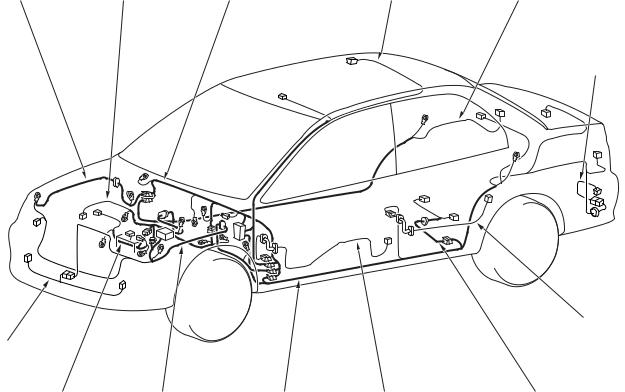
OVERALL WIRING DIAGRAM <SEDAN (LHD)>
M1801000101261
Front wiring |
Control wiring |
Instrument panel |
Roof wiring |
Floor wiring |
harness (RH) |
harness |
wiring harness |
harness |
harness (RH) |
Rear bumper wiring harness
Rear door wiring harness *
Front bumper wiring harness
Battery wiring |
Front wiring |
Floor wiring |
Front door |
Fuel wiring |
harness |
harness (LH) |
harness (LH) |
wiring harness * |
harness |
AC301175AB
NOTE:
1.This illustration shows only major wiring harnesses.
2.*: also equipped at the right side.
CONFIGURATION DIAGRAMS |
80-3 |
OVERALL CONFIGURATION DIAGRAM |
|
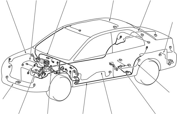
OVERALL WIRING DIAGRAM <SEDAN (RHD)>
M1801000101272
Front wiring |
Control wiring |
Instrument panel |
Roof wiring |
Floor wiring |
harness (RH) |
harness |
wiring harness |
harness |
harness (RH) |
Rear bumper wiring harness
Rear door wiring harness *
Front bumper wiring harness
Battery wiring |
Front wiring |
Floor wiring |
Front door |
Fuel wiring |
harness |
harness (LH) |
harness (LH) |
wiring harness * |
harness |
AC301176 AB
NOTE:
1.This illustration shows only major wiring harnesses.
2.*: also equipped at the right side.
80-4 |
CONFIGURATION DIAGRAMS |
|
OVERALL CONFIGURATION DIAGRAM |
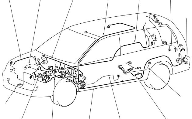
OVERALL WIRING DIAGRAM <WAGON (LHD)>
M1801000101283
Front wiring |
Control wiring |
Instrument panel |
Roof wiring |
Floor wiring |
Tailgate wiring |
harness (RH) |
harness |
wiring harness |
harness |
harness (RH) |
harness |
Rear bumper wiring harness
Rear door wiring harness *
Front bumper wiring harness
Battery wiring |
Front wiring |
Floor wiring |
Front door |
Fuel wiring |
harness |
harness (LH) |
harness (LH) |
wiring harness * |
harness |
AC301177AB
NOTE:
1.This illustration shows only major wiring harnesses.
2.*: also equipped at the right side.
CONFIGURATION DIAGRAMS |
80-5 |
OVERALL CONFIGURATION DIAGRAM |
|
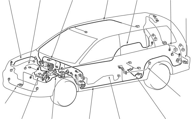
OVERALL WIRING DIAGRAM <WAGON (RHD)>
M1801000101294
Front wiring |
Control wiring |
Instrument panel |
Roof wiring |
Floor wiring |
Tailgate wiring |
harness (RH) |
harness |
wiring harness |
harness |
harness (RH) |
harness |
Rear bumper wiring harness
Rear door wiring harness *
Front bumper wiring harness
Battery wiring |
Front wiring |
Floor wiring |
Front door |
Fuel wiring |
harness |
harness (LH) |
harness (LH) |
wiring harness * |
harness |
AC301178 AB
NOTE:
1.This illustration shows only major wiring harnesses.
2.*: also equipped at the right side.
80-6 |
CONFIGURATION DIAGRAMS |
|
ENGINE COMPARTMENT |
|
ENGINE COMPARTMENT |
|
|
||
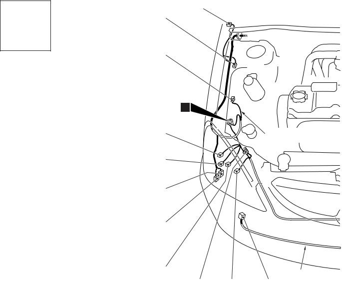
ENGINE COMPARTMENT <LHD> |
|
|
|
||
|
M1801000302440 |
|
|
|
|
Connector |
A-01 |
|
|
|
|
symbol |
A-32 |
|
|
|
|
A |
|
|
|
||
|
|
|
|
||
|
A-31 |
|
|
|
|
|
1 |
|
|
|
|
|
A-29 |
|
Front wiring |
||
|
|
|
harness (RH) |
||
|
A-28 |
|
|
|
|
|
A-27 |
|
|
|
|
Connector colour |
|
|
|
|
|
code |
A-26 |
|
|
|
|
B : Black |
|
|
|
||
|
|
|
|
||
BR : Brown |
|
|
|
|
|
G : Green |
|
|
|
|
|
GR : Grey |
|
|
|
|
|
L : Blue |
|
|
|
|
|
None : Milk white |
|
|
|
|
|
O : Orange |
A-25 |
|
|
|
|
R : Red |
|
|
Front bumper |
||
|
|
|
|||
V : Violet |
|
|
|
||
A-24 |
A-23 |
A-22 |
wiring harness |
||
Y : Yellow |
|||||
|
|||||
|
|
|
|
||
AC301123AC
A-01 |
(2-GR) |
Side turn signal lamp (RH) |
A-02 |
(2-GR) |
Side turn signal lamp (LH) |
A-03 |
(2-B) |
Wheel speed sensor (Front: LH) |
A-04X |
(4) |
Front fog lamp relay or spare connector |
|
|
(for front fog lamp) |
A-05X |
(4) |
Horn relay |
A-09X |
(4) |
Fan control relay |
A-10X |
(11) |
Front-ECU |
A-11X |
(11) |
Front-ECU |
A-12 |
(2-B) |
Front wiring harness (LH) and control |
|
|
wiring harness combination |
A-13 |
(12-B) |
Front wiring harness (LH) and control |
|
|
wiring harness combination |
A-14 |
(3-B) |
Headlamp (LH) |
A-15 |
(6-B) |
Front combination lamp (LH) |
A-16 |
(2) |
Front turn signal lamp (LH) |

CONFIGURATION DIAGRAMS |
80-7 |
ENGINE COMPARTMENT |
|
A-02
A-03
A-04X
A-05X
A-09X
A-10X
A-11X
A-12 |
|
|
|
Front wiring |
|
|
|
harness (LH) |
A-33 |
A-21 |
A-20 |
A-19 |
A-17 |
(2-B) |
Front fog lamp (LH) |
A-18 |
(3-GR) |
Cooling fan motor drive control unit |
A-19 |
(1-B) |
Horn (HI) |
A-20 |
(2-B) |
Front wiring harness (LH) and front |
|
|
bumper wiring harness combination |
A-21 |
(1-B) |
Horn (LO) |
A-22 |
(2-B) |
Front fog lamp (RH) |
A-23 |
(2) |
Front turn signal lamp (RH) |
A-24 |
(1) |
Spare connector (for front fog lamp) |
A-13
12
A-14
A-15
A-16
A-17
A-18
|
|
AC502048AB |
A-25 |
(6-B) |
Front combination lamp (RH) |
A-26 |
(2) |
Windshield washer motor |
A-27 |
(2-G) |
Rear washer motor |
A-28 |
(2-B) |
Headlamp washer motor |
A-29 |
(3-B) |
Headlamp (RH) |
A-31 |
(2-BR) |
Dual pressure switch |
A-32 |
(2-B) |
Wheel speed sensor (Front: RH) |
A-33 |
(2-BR) |
Outside thermo sensor <Automatic A/C> |
80-8 |
CONFIGURATION DIAGRAMS |
|
ENGINE COMPARTMENT |
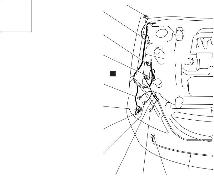
ENGINE COMPARTMENT <RHD>
M1801000302451
Connector |
A-01 |
symbol |
A-32 |
|
A
A-31
A-30 |
Front wiring |
|
harness (RH) |
1 
A-29
Connector colour code
B : Black BR : Brown G : Green GR : Grey L : Blue
None : Milk white O : Orange
R : Red
V : Violet
Y : Yellow
A-27 |
A-26
A-25
|
|
|
Front bumper |
A-24 |
A-23 |
A-22 |
wiring harness |
|
|||
|
AC301126AC
A-01 |
(2-GR) |
Side turn signal lamp (RH) |
A-02 |
(2-GR) |
Side turn signal lamp (LH) |
A-03 |
(2-B) |
Wheel speed sensor (Front: LH) |
A-04X |
(4) |
Front fog lamp relay or spare connector |
|
|
(for front fog lamp) |
A-05X |
(4) |
Horn relay |
A-09X |
(4) |
Fan control relay |
A-10X |
(11) |
Front-ECU |
A-11X |
(11) |
Front-ECU |
A-12 |
(2-B) |
Front wiring harness (LH) and control |
|
|
wiring harness combination |
A-14 |
(3-B) |
Headlamp (LH) |
A-15 |
(6-B) |
Front combination lamp (LH) |
A-16 |
(2) |
Front turn signal lamp (LH) |
A-17 |
(2-B) |
Front fog lamp (LH) |
CONFIGURATION DIAGRAMS |
80-9 |
ENGINE COMPARTMENT |
|
A-02
A-03
A-04X
A-05X
A-09X
A-10X
A-11X

 A-12
A-12
12
 A-14
A-14
A-15
A-16
A-17
|
|
Front wiring |
|
|
|
harness |
(LH) |
A-33 A-21 |
A-20 |
A-19 |
A-18 |
AC502049AB
A-18 |
(3-GR) |
Cooling fan motor drive control unit |
A-19 |
(1-B) |
Horn (HI) |
A-20 |
(2-B) |
Front wiring harness (LH) and front |
|
|
bumper wiring harness combination |
A-21 |
(1-B) |
Horn (LO) |
A-22 |
(2-B) |
Front fog lamp (RH) |
A-23 |
(2) |
Front turn signal lamp (RH) |
A-24 |
(1) |
Spare connector (for front fog lamp) |
A-25 |
(6-B) |
Front combination lamp (RH) |
A-26 |
(2) |
Windshield washer motor |
A-27 |
(2-G) |
Rear washer motor |
A-29 |
(3-B) |
Headlamp (RH) |
A-30 |
(2-GR) |
No connection |
A-31 |
(2-BR) |
Dual pressure switch |
A-32 |
(2-B) |
Wheel speed sensor (Front: RH) |
A-33 |
(2-BR) |
Outside thermo sensor <Automatic A/C> |
80-10 |
CONFIGURATION DIAGRAMS |
|
ENGINE AND TRANSMISSION |
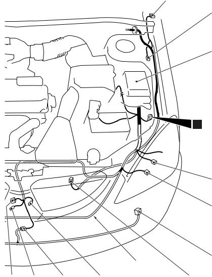
ENGINE AND TRANSMISSION
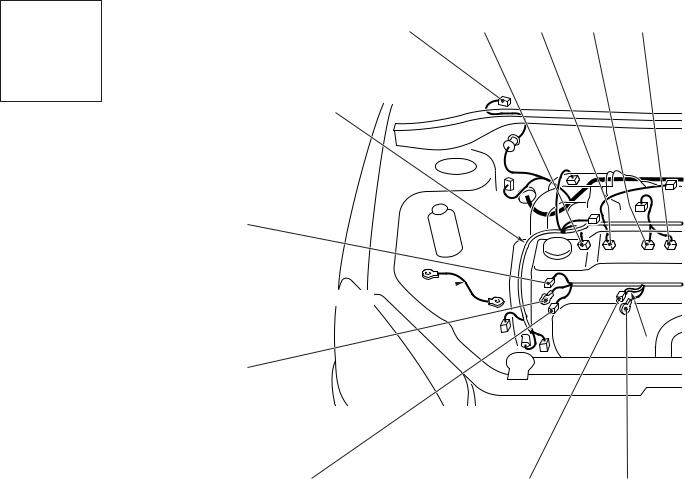
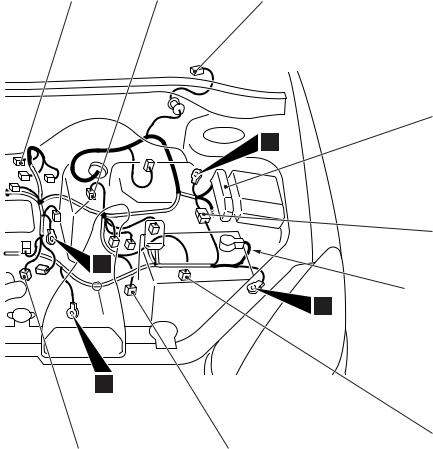
ENGINE AND TRANSMISSION <4G1-MPI (LHD)>
Connector symbol
B -01 thru -26
Connector colour code
B : Black BR : Brown G : Green GR : Grey L : Blue
None : Milk white O : Orange
R : Red
V : Violet
Y : Yellow
M1801000401949
B-01 |
B-02 |
B-03 |
B-04 |
B-05 |
Control wiring harness
B-26
Earth cable 
*
B-25
B-24 |
B-23 |
B-22 |
AC301129AD
B-01 |
(5-GR) |
Windshield wiper motor |
B-02 |
(2-GR) |
Fuel injector 1 |
B-03 |
(2-GR) |
Fuel injector 2 |
B-04 |
(2-GR) |
Fuel injector 3 |
B-05 |
(2-GR) |
Fuel injector 4 |
B-06 |
(3-GR) |
Throttle body throttle sensor |
B-07 |
(3-B) |
Vehicle speed sensor <M/T> |
B-09 |
(2-GR) |
Brake fluid level indicator switch |
B-10X |
(1) |
Engine speed detection connector |
B-15X |
(4) |
A/T control relay |
B-16X |
(4) |
Engine control relay |
B-17X |
(4) |
A/C compressor relay |
CONFIGURATION DIAGRAMS |
80-11 |
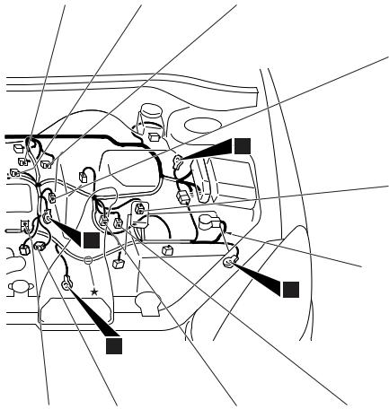
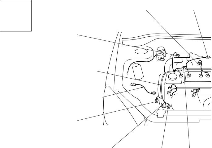
ENGINE AND TRANSMISSION |
|
B-06 |
B-07 |
B-09 |
13
10
11
 *
*
9
|
B-21 |
B-20 |
B-18 |
(6-B) |
Control wiring harness and battery wiring |
|
|
harness combination |
B-19 |
(10-GR) A/T control solenoid valve assembly |
|
B-20 |
(10-B) |
Inhibitor switch <A/T> |
B-21 |
(4-B) |
Engine control oxygen sensor (Front) |
B-22 |
(1) |
Starter |
B-23 |
(1-B) |
Starter |
B-24 |
(1-B) |
Engine oil pressure switch |
B-10X
B-15X
B-16X
B-17X
B-18
Battery wiring harness
B-19
AC301130AB
B-25 |
(1) |
Alternator |
B-26 |
(4-GR) |
Alternator |
NOTE: On A/T only, the standard routing positions for the corrugated tube and wiring harness are marked by*.
80-12 |
CONFIGURATION DIAGRAMS |
|
ENGINE AND TRANSMISSION |
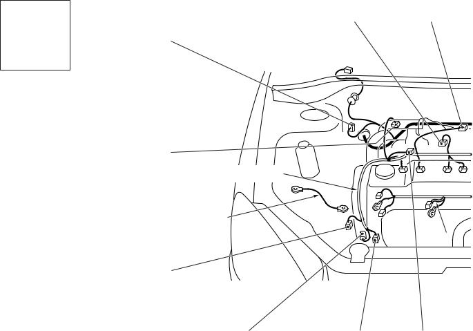
ENGINE AND TRANSMISSION <4G1-MPI (LHD)> (CONTINUED)
Connector symbol
B -101 thru -118
Connector colour code
B : Black BR : Brown G : Green GR : Grey L : Blue
None : Milk white O : Orange
R : Red
V : Violet
Y : Yellow
B-101 |
B-102 |
B-118
B-117
Control wiring harness
Earth cable
*
B-116
B-115 |
B-114 |
B-113 |
AC301129AE
B-101 (2-BR) |
Emission solenoid valve (EGR system) |
|
B-102 |
(4-GR) |
Inlet manifold absolute pressure sensor |
B-103 |
(6-B) |
Throttle body idle speed control servo |
B-104 |
(3-GR) |
Ignition coil 1 |
B-105 |
(2-B) |
Emission solenoid valve (Purge control |
|
|
system) |
B-107 |
(3-B) |
Camshaft position sensor |
B-108 |
(3-GR) |
Output shaft speed sensor <A/T> |
B-109 |
(3-B) |
Input shaft speed sensor <A/T> |
B-110 |
(2-B) |
Back-up lamp switch <M/T> |
B-111 |
(2-B) |
Water temperature sensor unit |
CONFIGURATION DIAGRAMS |
80-13 |
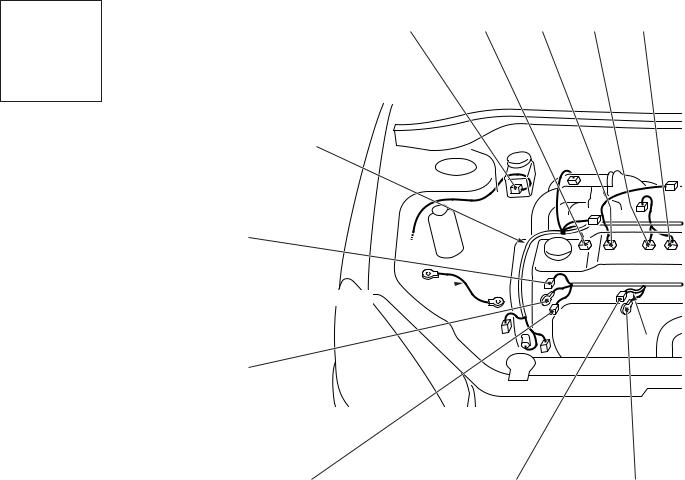
ENGINE AND TRANSMISSION |
|
B-103 |
B-104 |
B-105 |
B-107
|
13 |
|
B-108 |
10 |
|
|
Battery wiring |
|
harness |
* |
11 |
|
9 |
B-112 |
B-111 |
B-110 |
B-109 |
AC301130AC
B-112 |
(1-B) |
Water temperature gauge unit |
B-113 |
(3-GR) |
Ignition coil 2 |
B-114 |
(1-B) |
A/C compressor |
B-115 |
(1) |
Power steering fluid pressure switch |
B-116 |
(3-B) |
Engine crank angle sensor |
B-117 |
(2-GR) |
Engine control detonation sensor |
B-118 |
(28-GR) ABS-ECU |
|
NOTE: On A/T only, the standard routing positions for the corrugated tube and wiring harness are marked by*.
80-14 |
CONFIGURATION DIAGRAMS |
|
ENGINE AND TRANSMISSION |
ENGINE AND TRANSMISSION <4G1-MPI (RHD)>
Connector symbol
B -01 thru -26
Connector colour code
B : Black BR : Brown G : Green GR : Grey L : Blue
None : Milk white O : Orange
R : Red
V : Violet
Y : Yellow
M1801000401950
B-09 |
B-02 |
B-03 |
B-04 |
B-05 |
Control wiring harness
B-26
Earth cable 
*
B-25
B-24 |
B-23 |
B-22 |
AC301132AD
B-01 |
(5-GR) |
Windshield wiper motor |
B-02 |
(2-GR) |
Fuel injector 1 |
B-03 |
(2-GR) |
Fuel injector 2 |
B-04 |
(2-GR) |
Fuel injector 3 |
B-05 |
(2-GR) |
Fuel injector 4 |
B-06 |
(3-GR) |
Throttle body throttle sensor |
B-07 |
(3-B) |
Vehicle speed sensor <M/T> |
B-09 |
(2-GR) |
Brake fluid level indicator switch |
B-10X |
(1) |
Engine speed detection connector |
B-14X |
(4) |
Ignition coil relay |
B-15X |
(4) |
A/T control relay |
B-16X |
(4) |
Engine control relay |
CONFIGURATION DIAGRAMS |
80-15 |
ENGINE AND TRANSMISSION |
|
B-06 |
B-07 |
B-01 |
13
10
11
 *
*
9
B-10X
B-14X
B-15X
B-16X
B-17X
B-18
Battery wiring harness
B-19
B-21 |
B-20 |
AC301133 AB
B-17X |
(4) |
A/C compressor relay |
B-18 |
(6-B) |
Control wiring harness and battery wiring |
|
|
harness combination |
B-19 |
(10-GR) A/T control solenoid valve assembly |
|
B-20 |
(10-B) |
Inhibitor switch <A/T> |
B-21 |
(4-B) |
Engine control oxygen sensor (Front) |
B-22 |
(1) |
Starter |
B-23 |
(1-B) |
Starter |
B-24 |
(1-B) |
Engine oil pressure switch |
B-25 |
(1) |
Alternator |
B-26 |
(4-GR) |
Alternator |
NOTE: On A/T only, the standard routing positions for the corrugated tube and wiring harness are marked by*.
80-16 |
CONFIGURATION DIAGRAMS |
|
ENGINE AND TRANSMISSION |
ENGINE AND TRANSMISSION <4G1-MPI (RHD)> (CONTINUED)
Connector symbol
B -101 thru -118
Connector colour code
B : Black BR : Brown G : Green GR : Grey L : Blue
None : Milk white O : Orange
R : Red
V : Violet
Y : Yellow
B-101 |
B-102 |
B-117
Control wiring harness
Earth cable
*
B-116
B-115 |
B-114 |
B-113 |
AC301132AE
B-101 (2-BR) |
Emission solenoid valve (EGR system) |
|
B-102 |
(4-GR) |
Inlet manifold absolute pressure sensor |
B-103 |
(6-B) |
Throttle body idle speed control servo |
B-104 |
(3-GR) |
Ignition coil 1 |
B-105 |
(2-B) |
Emission solenoid valve (Purge control |
|
|
system) |
B-107 |
(3-B) |
Camshaft position sensor |
B-108 |
(3-GR) |
Output shaft speed sensor <A/T> |
B-109 |
(3-B) |
Input shaft speed sensor <A/T> |
B-110 |
(2-B) |
Back-up lamp switch <M/T> |

CONFIGURATION DIAGRAMS |
80-17 |
ENGINE AND TRANSMISSION |
|
B-103 |
B-104 |
B-105 |
B-118 |
B-107
|
13 |
|
B-108 |
10 |
|
|
Battery wiring |
|
harness |
* |
11 |
|
9 |
B-112 |
B-111 |
B-110 |
B-109 |
AC301133 AC
B-111 |
(2-B) |
Water temperature sensor unit |
B-112 |
(1-B) |
Water temperature gauge unit |
B-113 |
(3-GR) |
Ignition coil 2 |
B-114 |
(1-B) |
A/C compressor |
B-115 |
(1) |
Power steering fluid pressure switch |
B-116 |
(3-B) |
Engine crank angle sensor |
B-117 |
(2-GR) |
Engine control detonation sensor |
B-118 (28-GR) ABS-ECU
NOTE: On A/T only, the standard routing positions for the corrugated tube and wiring harness are marked by*.
Loading...