

Page 1

iPM-9800 Patient Monitor
Operator’s Manual
Page 2

Page 3

I
© Copyright 2009-2010 Shenzhen Mindray Bio-Medical Electronics Co., Ltd. All rights
reserved.
For this Operator’s Manual, the issue date is 2010-06.
Page 4

II
Intellectual Property Statement
SHENZHEN MINDRAY BIO-MEDICAL ELECTRONICS CO., LTD. (hereinafter called
Mindray) owns the intellectual property rights to this Mindray product and this manual. This
manual may refer to information protected by copyright or patents and does not convey any
license under the patent rights or copyright of Mindray, or of others.
Mindray intends to maintain the contents of this manual as confidential information.
Disclosure of the information in this manual in any manner whatsoever without the written
permission of Mindray is strictly forbidden. Release, amendment, reproduction, distribution,
rental, adaptation, translation or any other derivative work of this manual in any manner
whatsoever without the written permission of Mindray is strictly forbidden.
, and are the registered trademarks or trademarks owned
by Mindray in China and other countries. All other trademarks that appear in this manual are
used only for editorial purposes without the intention of improperly using them. They are the
property of their respective owners.
Page 5

III
Responsibility on the Manufacturer
Party
Contents of this manual are subject to change without prior notice.
All information contained in this manual is believed to be correct. Mindray shall not be liable
for errors contained herein or for incidental or consequential damages in connection with the
furnishing, performance, or use of this manual.
Mindray is responsible for the effects on safety, reliability and performance of this product,
only if:
all installation operations, expansions, changes, modifications and repairs of this product
are conducted by Mindray authorized personnel;
the electrical installation of the relevant room complies with the applicable national and
local requirements;and
the product is used in accordance with the instructions for use.
NOTE
z This equipment must be operated by skilled/trained clinical professionals.
WARNING
z It is important for the hospital or organization that employs this equipment to
carry out a reasonable service/maintenance plan. Neglect of this may result in
machine breakdown or personal injury.
Page 6

IV
Warranty
THIS WARRANTY IS EXCLUSIVE AND IS IN LIEU OF ALL OTHER WARRANTIES,
EXPRESSED OR IMPLIED, INCLUDING WARRANTIES OF MERCHANTABILITY OR
FITNESS FOR ANY PARTICULAR PURPOSE.
Exemptions
Mindray's obligation or liability under this warranty does not include any transportation or
other charges or liability for direct, indirect or consequential damages or delay resulting from
the improper use or application of the product or the use of parts or accessories not approved
by Mindray or repairs by people other than Mindray authorized personnel.
This warranty shall not extend to:
Malfunction or damage caused by improper use or man-made failure.
Malfunction or damage caused by unstable or out-of-range power input.
Malfunction or damage caused by force majeure such as fire and earthquake.
Malfunction or damage caused by improper operation or repair by unqualified or
unauthorized service people.
Malfunction of the instrument or part whose serial number is not legible enough.
Others not caused by instrument or part itself.
Page 7

V
Company Contact
Manufacturer: Shenzhen Mindray Bio-Medical Electronics Co., Ltd.
E-mail Address: service@mindray.com
Tel: +86 755 26582479 26582888
Fax: +86 755 26582934 26582500
EC-Representative: Shanghai International Holding Corp. GmbH(Europe)
Address: Eiffestraβe 80, Hamburg 20537, Germany
Tel: 0049-40-2513175
Fax: 0049-40-255726
Page 8

VI
Preface
Manual Purpose
This manual contains the instructions necessary to operate the product safely and in
accordance with its function and intended use. Observance of this manual is a prerequisite for
proper product performance and correct operation and ensures patient and operator safety.
This manual is based on the maximum configuration and therefore some contents may not
apply to your product. If you have any question, please contact us.
This manual is an integral part of the product. It should always be kept close to the equipment
so that it can be obtained conveniently when needed.
Intended Audience
This manual is geared for clinical professionals who are expected to have a working
knowledge of medical procedures, practices and terminology as required for monitoring of
critically ill patients.
Illustrations
All illustrations in this manual serve as examples only. They may not necessarily reflect the
setup or data displayed on your patient monitor.
Conventions
Italic text is used in this manual to quote the referenced chapters or sections.
[ ] is used to enclose screen texts.
→ is used to indicate operational procedures.
Page 9

1
Content
1 Safety................................................................................................................................. 1-1
1.1 Safety Information ..........................................................................................................1-1
1.1.1 Dangers .............................................................................................................. 1-2
1.1.2 Warnings............................................................................................................. 1-2
1.1.3 Cautions ............................................................................................................. 1-3
1.1.4 Notes .................................................................................................................. 1-3
1.2 Equipment Symbols ........................................................................................................ 1-4
2 The Basics ......................................................................................................................... 2-1
2.1 Monitor Description........................................................................................................ 2-1
2.1.1 Intended Use....................................................................................................... 2-1
2.1.2 Contraindications ............................................................................................... 2-1
2.1.3 Components ....................................................................................................... 2-1
2.2 Main unit......................................................................................................................... 2-2
2.2.1 Front View.......................................................................................................... 2-2
2.2.2 Side View ........................................................................................................... 2-4
2.2.3 Rear View........................................................................................................... 2-5
2.3 Display Screen ................................................................................................................ 2-6
2.4 QuickKeys....................................................................................................................... 2-8
3 Basic Operations ..............................................................................................................3-1
3.1 Installation....................................................................................................................... 3-1
3.1.1 Unpacking and Checking ................................................................................... 3-2
3.1.2 Environmental Requirements............................................................................. 3-2
3.2 Getting Started ................................................................................................................ 3-3
3.2.1 Inspecting the Monitor ....................................................................................... 3-3
3.2.2 Switching On...................................................................................................... 3-3
3.2.3 Starting Monitoring............................................................................................ 3-3
3.3 Disconnecting from Power.............................................................................................. 3-4
3.4 Operating and Navigating ............................................................................................... 3-4
3.4.1 Using the Knob .................................................................................................. 3-4
3.4.2 Using Keys......................................................................................................... 3-5
3.4.3 Using the Touchscreen ....................................................................................... 3-5
3.4.4 Using the On-Screen Keyboard.......................................................................... 3-5
3.4.5 Using the Main Menu......................................................................................... 3-6
3.5 Operating Modes.............................................................................................................3-7
3.6 Using an External Storage Device................................................................................... 3-8
3.7 Using an External Display .............................................................................................. 3-9
3.8 Changing General Measurement Settings....................................................................... 3-9
Page 10

2
3.8.1 Switching On/Off Modules ................................................................................ 3-9
3.8.2 Changing Measurement Settings...................................................................... 3-10
3.8.3 Changing Waveform Settings........................................................................... 3-10
3.9 Changing General Settings............................................................................................ 3-10
3.9.1 Setting up a Monitor..........................................................................................3-11
3.9.2 Changing Language ..........................................................................................3-11
3.9.3 Setting DIAP Baud Rate....................................................................................3-11
3.9.4 Adjusting the Screen Brightness .......................................................................3-11
3.9.5 Setting the Date and Time ................................................................................ 3-12
3.9.6 Adjusting Volume............................................................................................. 3-13
4 Managing Patients............................................................................................................ 4-1
4.1 Admitting a Patient.......................................................................................................... 4-1
4.2 Editing Patient Information............................................................................................. 4-2
4.3 Discharging a Patient ...................................................................................................... 4-2
4.4 Switching between Wire and Wireless Networks............................................................ 4-3
4.5 Transferring Patient Data ................................................................................................ 4-3
4.6 Connecting to a Central Monitoring System................................................................... 4-5
5 Managing Configurations................................................................................................ 5-1
5.1 Introduction..................................................................................................................... 5-1
5.2 Entering and Exiting the Configuration Mode................................................................ 5-2
5.3 Viewing and Changing Configurations........................................................................... 5-3
5.4 Adding a Configuration................................................................................................... 5-4
5.5 Deleting a Configuration................................................................................................. 5-4
5.6 Loading a Configuration ................................................................................................. 5-5
5.7 Setting Default Configuration at Startup......................................................................... 5-5
5.8 Loading the Latest Configuration Automatically............................................................ 5-6
5.9 Transferring a Configuration........................................................................................... 5-7
6 User Screens...................................................................................................................... 6-1
6.1 Tailoring Your Screens .................................................................................................... 6-1
6.1.1 Setting the Waveform Sweep Mode ................................................................... 6-1
6.1.2 Changing the Wave Line Size ............................................................................ 6-1
6.1.3 Choosing the Way to Draw Waves..................................................................... 6-1
6.1.4 Changing Parameter and Waveform Colors ....................................................... 6-2
6.1.5 Selecting Waveforms for Display....................................................................... 6-2
6.1.6 Changing Screen Layout .................................................................................... 6-2
6.2 Viewing Minitrends......................................................................................................... 6-3
6.2.1 Having a Split-Screen View of Minitrends ........................................................ 6-3
6.2.2 Changing Minitrend Length............................................................................... 6-4
6.2.3 Changing a Parameter for Viewing .................................................................... 6-4
6.3 Viewing oxyCRG............................................................................................................ 6-5
6.4 Viewing Other Patients.................................................................................................... 6-6
Page 11

3
6.4.1 Care Group......................................................................................................... 6-6
6.4.2 Viewing the Care Group Overview Bar ............................................................. 6-6
6.4.3 Understanding the View Other Patient Window ................................................ 6-7
6.5 Understanding the Big Numerics Screen ........................................................................ 6-8
7 Alarms............................................................................................................................... 7-1
7.1 Alarm Categories............................................................................................................. 7-1
7.2 Alarm Levels ................................................................................................................... 7-2
7.3 Alarm Indicators.............................................................................................................. 7-2
7.3.1 Alarm Lamp ....................................................................................................... 7-3
7.3.2 Alarm Message................................................................................................... 7-3
7.3.3 Flashing Numeric ............................................................................................... 7-3
7.3.4 Audible Alarm Tones.......................................................................................... 7-3
7.3.5 Reminder Tones.................................................................................................. 7-4
7.4 Understanding Alarm Statuses ........................................................................................ 7-4
7.4.1 Pausing Alarms................................................................................................... 7-4
7.4.2 Switching Off Alarms......................................................................................... 7-5
7.4.3 Silencing the Alarm Sound................................................................................. 7-5
7.4.4 Switching off Alarm Sound................................................................................ 7-6
7.5 Alarm Configuration ....................................................................................................... 7-6
7.5.1 Alarm Tone Configuration.................................................................................. 7-6
7.5.2 Displaying Alarm Limits.................................................................................... 7-7
7.5.3 Setting Alarm Delay Time.................................................................................. 7-7
7.5.4 Using Alarms...................................................................................................... 7-7
7.5.5 Mass Alarm Setup .............................................................................................. 7-9
7.5.6 Adjusting Alarm Limits Automatically .............................................................. 7-9
7.6 Latching Alarms .............................................................................................................. 7-9
7.7 Clearing Technical Alarms ............................................................................................ 7-10
7.8 Testing Alarms .............................................................................................................. 7-10
7.9 When an Alarm Occurs ................................................................................................. 7-10
7.10 Using Care Group Alarms............................................................................................7-11
7.10.1 Care Group Auto Alarms.................................................................................7-11
7.10.2 Viewing Alarm Information ............................................................................7-11
7.10.3 Silencing Care Group Alarms ........................................................................ 7-12
8 Monitoring ECG ..............................................................................................................8-1
8.1 Introduction..................................................................................................................... 8-1
8.2 Safety .............................................................................................................................. 8-1
8.3 Preparing to Monitor ECG .............................................................................................. 8-2
8.3.1 Preparing the Patient and Placing the Electrodes............................................... 8-2
8.3.2 Choosing a Lead Set and AHA or IEC Lead Placement .................................... 8-2
8.3.3 ECG Lead Placements........................................................................................ 8-3
8.3.4 Switching ECG Lead Set.................................................................................... 8-5
8.3.5 Checking Paced Status ....................................................................................... 8-6
Page 12

4
8.4 Understanding the ECG Display..................................................................................... 8-7
8.5 Changing ECG Settings .................................................................................................. 8-8
8.5.1 Setting Pacemaker Rate (For Mortara Only)...................................................... 8-8
8.5.2 Choosing the Alarm Source................................................................................ 8-8
8.5.3 Choosing a 5-Lead ECG Display Screen ........................................................... 8-8
8.5.4 Changing the ECG Filter Settings...................................................................... 8-9
8.5.5 Switching the Notch Filter On or Off................................................................. 8-9
8.5.6 Switching Defibrillator Synchronization On/Off............................................. 8-10
8.5.7 Selecting ECG Waves for Display ....................................................................8-11
8.5.8 Changing ECG Wave Settings ..........................................................................8-11
8.5.9 Choosing an ECG Lead for HR Computing and Arrh. Monitoring...................8-11
8.5.10 Adjusting QRS Volume .................................................................................. 8-12
8.6 About ST Monitoring .................................................................................................... 8-12
8.6.1 Switching ST On and Off................................................................................. 8-12
8.6.2 Changing ST Filter Settings ............................................................................. 8-13
8.6.3 Understanding the ST Display ......................................................................... 8-13
8.6.4 Changing the ST Unit....................................................................................... 8-13
8.6.5 Changing the ST Alarm Limits ........................................................................ 8-13
8.6.6 Setting ST Alarm Delay Time.......................................................................... 8-14
8.6.7 Adjusting ST Measurement Points................................................................... 8-14
8.7 About Arrhythmia Monitoring ...................................................................................... 8-15
8.7.1 Understanding the Arrhythmia Events ............................................................. 8-16
8.7.2 Switching Arrhythmia Analysis On and Off .................................................... 8-18
8.7.3 Changing Arrhythmia Alarm Settings .............................................................. 8-18
8.7.4 Changing Arrhythmia Threshold Settings (For Mortara Only) ........................ 8-18
8.7.5 Initiating Arrhythmia Relearning Manually ..................................................... 8-19
8.7.6 Automatic Arrhythmia Relearn ........................................................................ 8-20
8.7.7 Reviewing Arrhythmia Events ......................................................................... 8-20
8.8 12-Lead ECG Monitoring ............................................................................................. 8-21
8.8.1 Entering the 12-lead ECG Monitoring Screen ................................................. 8-21
8.8.2 Interpretation of resting 12-Lead ECG............................................................. 8-22
8.8.3 Reviewing Interpretation of resting 12-Lead ECG Results.............................. 8-23
9 Monitoring Respiration (Resp)....................................................................................... 9-1
9.1 Introduction..................................................................................................................... 9-1
9.2 Safety .............................................................................................................................. 9-1
9.3 Placing Resp Electrodes.................................................................................................. 9-1
9.3.1 Optimizing Lead Placement for Resp ................................................................ 9-2
9.3.2 Cardiac Overlay ................................................................................................. 9-2
9.3.3 Abdominal Breathing ......................................................................................... 9-2
9.3.4 Lateral Chest Expansion..................................................................................... 9-3
9.4 Understanding the Resp Display..................................................................................... 9-3
9.5 Changing Resp Settings .................................................................................................. 9-3
9.5.1 Choosing the Respiration Lead .......................................................................... 9-3
Page 13

5
9.5.2 Setting the Apnea Alarm Delay .......................................................................... 9-3
9.5.3 Changing Resp Detection Mode ........................................................................ 9-4
9.5.4 Changing the Size of the Resp Wave ................................................................. 9-5
10 Monitoring PR.............................................................................................................. 10-1
10.1 Introduction................................................................................................................. 10-1
10.2 Changing PR Settings ................................................................................................. 10-1
10.2.1 Setting the PR Source..................................................................................... 10-1
10.2.2 Selecting the Active Alarm Source................................................................. 10-2
10.2.3 Adjusting QRS Volume .................................................................................. 10-2
11 Monitoring SpO
2
...........................................................................................................11-1
11.1 Introduction..................................................................................................................11-1
11.2 Safety............................................................................................................................11-2
11.3 Identifying SpO
2
Modules............................................................................................11-2
11.4 Applying the Sensor .....................................................................................................11-2
11.5 Changing SpO
2
Settings ...............................................................................................11-3
11.5.1 Adjusting the Desat Alarm Limit.....................................................................11-3
11.5.2 Setting SpO
2
Sensitivity ..................................................................................11-3
11.5.3 Changing Averaging Time...............................................................................11-3
11.5.4 Monitoring SpO
2
and NIBP Simultaneously...................................................11-4
11.5.5 Sat-Seconds Alarm Management ....................................................................11-4
11.5.6 Pitch Tone........................................................................................................11-5
11.6 Measurement Limitations.............................................................................................11-6
11.7 Masimo Information.....................................................................................................11-6
11.8 Nellcor Information......................................................................................................11-7
12 Monitoring NIBP.......................................................................................................... 12-1
12.1 Introduction................................................................................................................. 12-1
12.2 Safety .......................................................................................................................... 12-2
12.3 Measurement Limitations............................................................................................ 12-2
12.4 Setting Up the NIBP Measurement ............................................................................. 12-3
12.4.1 Preparing to Measure NIBP ........................................................................... 12-3
12.4.2 Starting and Stopping Measurements............................................................. 12-3
12.4.3 Correcting the Measurement if Limb is not at Heart Level............................ 12-3
12.5 Measurement Methods................................................................................................ 12-4
12.5.1 Enabling NIBP Auto Cycling and Setting the Interval ................................... 12-4
12.5.2 Starting a STAT Measurement........................................................................ 12-4
12.6 Understanding the NIBP Numerics............................................................................. 12-5
12.7 Changing NIBP Settings ............................................................................................. 12-6
12.7.1 Choosing NIBP Alarm Source ....................................................................... 12-6
12.7.2 Displaying NIBP Measurements .................................................................... 12-6
12.7.3 Setting the Pressure Unit................................................................................ 12-6
12.7.4 Setting the cuff inflation pressure .................................................................. 12-7
Page 14

6
12.8 Assisting Venous Puncture .......................................................................................... 12-7
12.9 Resetting NIBP ........................................................................................................... 12-7
12.10 NIBP Leakage Test.................................................................................................... 12-7
12.11 NIBP Accuracy Test .................................................................................................. 12-8
12.12 Calibrating NIBP....................................................................................................... 12-9
13 Monitoring Temp.......................................................................................................... 13-1
13.1 Introduction................................................................................................................. 13-1
13.2 Safety .......................................................................................................................... 13-1
13.3 Making a Temp Measurement..................................................................................... 13-1
13.4 Understanding the Temp Display ................................................................................ 13-2
13.5 Setting the Temperature Unit ...................................................................................... 13-2
14 Monitoring IBP ............................................................................................................ 14-1
14.1 Introduction................................................................................................................. 14-1
14.2 Safety .......................................................................................................................... 14-1
14.3 Setting Up the Pressure Measurement ........................................................................ 14-1
14.4 Understanding the IBP Display................................................................................... 14-3
14.5 Changing IBP Settings ................................................................................................ 14-4
14.5.1 Changing a Pressure for Monitoring .............................................................. 14-4
14.5.2 Choosing the Pressure Alarm Source ............................................................. 14-4
14.5.3 Changing Averaging Time.............................................................................. 14-5
14.5.4 Setting the Pressure Unit................................................................................ 14-5
14.5.5 Setting Wave Overlapping.............................................................................. 14-5
14.5.6 Setting Up the IBP Wave................................................................................ 14-5
14.6 Measuring PAWP ........................................................................................................ 14-6
14.6.1 Preparing to Measure PAWP.......................................................................... 14-6
14.6.2 Setting Up the PAWP Measurement............................................................... 14-8
14.7 Zeroing the Transducer ............................................................................................... 14-9
15 Monitoring Cardiac Output........................................................................................ 15-1
15.1 Introduction................................................................................................................. 15-1
15.2 Understanding the C.O. Display ................................................................................. 15-1
15.3 Influencing Factors...................................................................................................... 15-2
15.4 Setting Up the C.O. Measurement .............................................................................. 15-2
15.5 Measuring the Blood Temperature .............................................................................. 15-5
15.6 Changing C.O. Settings............................................................................................... 15-6
15.6.1 Setting the Temperature Unit ......................................................................... 15-6
15.6.2 Setting the Interval between Measurements................................................... 15-6
16 Monitoring Carbon Dioxide........................................................................................ 16-1
16.1 Introduction................................................................................................................. 16-1
16.2 Preparing to Measure CO
2
.......................................................................................... 16-2
16.2.1 Using a Sidestream CO
2
Module ................................................................... 16-2
Page 15

7
16.2.2 Using a Microstream CO2 module ................................................................. 16-3
16.2.3 Using a Mainstream CO
2
module................................................................... 16-4
16.3 Changing CO
2
Settings ............................................................................................... 16-5
16.3.1 Entering the Standby Mode............................................................................ 16-5
16.3.2 Setting the Pressure Unit................................................................................ 16-5
16.3.3 Setting up Gas Compensations....................................................................... 16-5
16.3.4 Setting up Humidity Compensation............................................................... 16-6
16.3.5 Setting the Apnea Alarm Delay ...................................................................... 16-7
16.3.6 Choosing a Time Interval for Peak-Picking ................................................... 16-7
16.3.7 Setting the Flow Rate..................................................................................... 16-7
16.3.8 Setting up the CO
2
Wave................................................................................ 16-7
16.4 Setting Barometric Pressure Compensation................................................................ 16-8
16.5 Measurement Limitations............................................................................................ 16-8
16.6 Troubleshooting the Sidestream CO
2
Sampling System ............................................. 16-8
16.7 Removing Exhaust Gases from the System ................................................................ 16-9
16.8 Zeroing the Sensor ...................................................................................................... 16-9
16.8.1 For Sidestream and Microstream CO
2
Modules............................................. 16-9
16.8.2 For Mainstream CO
2
Modules ....................................................................... 16-9
16.9 Calibrating the Sensor............................................................................................... 16-10
16.10 Oridion Information ................................................................................................ 16-10
17 Monitoring AG ............................................................................................................. 17-1
17.1 Introduction................................................................................................................. 17-1
17.2 Preparing to Measure AG............................................................................................ 17-2
17.3 Understanding the AG Display ................................................................................... 17-4
17.4 MAC Values ................................................................................................................ 17-5
17.5 Changing AG Settings................................................................................................. 17-6
17.5.1 Selecting an Anesthetic Gas for Monitoring .................................................. 17-6
17.5.2 Setting Gas Unit ............................................................................................. 17-6
17.5.3 Setting the Apnea Alarm Delay ...................................................................... 17-6
17.5.4 Changing the Sample Flow Rate.................................................................... 17-6
17.5.5 Setting up the O
2
Compensation .................................................................... 17-6
17.5.6 Entering the Standby Mode............................................................................ 17-7
17.5.7 Setting up the AG Wave ................................................................................. 17-7
17.6 Changing the Anesthetic Agent................................................................................... 17-7
17.7 Measurement Limitations............................................................................................ 17-8
17.8 Troubleshooting .......................................................................................................... 17-8
17.8.1 When the Gas Inlet is Blocked....................................................................... 17-8
17.8.2 When an Internal Occlusion Occurs............................................................... 17-8
17.9 Removing Exhaust Gases from the System ................................................................ 17-9
18 Freezing Waveforms .................................................................................................... 18-1
18.1 Freezing Waveforms ................................................................................................... 18-1
18.2 Viewing Frozen Waveforms ........................................................................................ 18-1
Page 16

8
18.3 Unfreezing Waveforms................................................................................................ 18-2
18.4 Recording Frozen Waveforms..................................................................................... 18-2
19 Review........................................................................................................................... 19-1
19.1 Accessing Respective Review Windows..................................................................... 19-1
19.2 Reviewing Graphic Trends.......................................................................................... 19-2
19.3 Reviewing Tabular Trends .......................................................................................... 19-4
19.4 Reviewing NIBP Measurements ................................................................................. 19-6
19.5 Reviewing Alarms....................................................................................................... 19-7
19.6 Reviewing Waveforms ................................................................................................ 19-8
20 Calculations .................................................................................................................. 20-1
20.1 Introduction................................................................................................................. 20-1
20.2 Dose Calculations........................................................................................................ 20-2
20.2.1 Performing Calculations................................................................................. 20-2
20.2.2 Selecting the Proper Drug Unit ...................................................................... 20-2
20.2.3 Titration Table ................................................................................................ 20-3
20.3 Oxygenation Calculations ........................................................................................... 20-3
20.3.1 Performing Calculations................................................................................. 20-3
20.3.2 Entered Parameters......................................................................................... 20-4
20.3.3 Calculated Parameters.................................................................................... 20-4
20.4 Ventilation Calculations .............................................................................................. 20-5
20.4.1 Performing Calculations................................................................................. 20-5
20.4.2 Entered Parameters......................................................................................... 20-5
20.4.3 Calculated Parameters.................................................................................... 20-6
20.5 Hemodynamic Calculations ........................................................................................ 20-6
20.5.1 Performing Calculations................................................................................. 20-6
20.5.2 Entered Parameters......................................................................................... 20-7
20.5.3 Calculated Parameters.................................................................................... 20-7
20.6 Renal Calculations ...................................................................................................... 20-8
20.6.1 Performing Calculations................................................................................. 20-8
20.6.2 Entered Parameters......................................................................................... 20-8
20.6.3 Calculated Parameters.................................................................................... 20-9
20.7 Understanding the Review Window............................................................................ 20-9
21 Recording...................................................................................................................... 21-1
21.1 Using a Recorder......................................................................................................... 21-1
21.2 Overview of Recording Types..................................................................................... 21-2
21.3 Starting and Stopping Recordings............................................................................... 21-3
21.4 Setting up the Recorder............................................................................................... 21-3
21.4.1 Accessing the Record Setup Menu................................................................. 21-3
21.4.2 Selecting Waveforms for Recording .............................................................. 21-3
21.4.3 Setting the Realtime Recording Length ......................................................... 21-4
21.4.4 Setting the Interval between Timed Recordings............................................. 21-4
Page 17

9
21.4.5 Changing the Recording Speed...................................................................... 21-4
21.4.6 Switching Gridlines On or Off....................................................................... 21-4
21.4.7 Clearing Recording Tasks .............................................................................. 21-4
21.5 Loading Paper ............................................................................................................. 21-4
21.6 Removing Paper Jam................................................................................................... 21-5
21.7 Cleaning the Recorder Printhead................................................................................. 21-6
22 Printing ......................................................................................................................... 22-1
22.1 Printer.......................................................................................................................... 22-1
22.2 Connecting a Printer.................................................................................................... 22-1
22.3 Setting Up the Printer.................................................................................................. 22-1
22.4 Starting Report Printouts............................................................................................. 22-2
22.5 Stopping Report Printouts........................................................................................... 22-3
22.6 Setting Up Reports...................................................................................................... 22-3
22.6.1 Setting Up ECG Reports ................................................................................ 22-3
22.6.2 Setting Up Tabular Trends Reports ................................................................ 22-3
22.6.3 Setting Up Graphic Trends Reports ............................................................... 22-4
22.6.4 Setting Up Realtime Reports.......................................................................... 22-4
22.7 End Case Reports........................................................................................................ 22-4
22.8 Printer Statuses............................................................................................................ 22-5
22.8.1 Printer Out of Paper ....................................................................................... 22-5
22.8.2 Printer Status Message ................................................................................... 22-5
23 Other Functions............................................................................................................ 23-1
23.1 Marking Events ........................................................................................................... 23-1
23.2 Analog Output ............................................................................................................. 23-1
23.3 Transferring Data ........................................................................................................ 23-2
23.3.1 Data Export System........................................................................................ 23-2
23.3.2 Transferring Data by Different Means ........................................................... 23-2
23.4 Nurse Call ................................................................................................................... 23-3
23.5 Wireless Network........................................................................................................ 23-5
24 Batteries........................................................................................................................ 24-1
24.1 Overview..................................................................................................................... 24-1
24.2 Installing or Replacing a Battery................................................................................. 24-2
24.3 Battery Guidelines....................................................................................................... 24-3
24.4 Battery Maintenance ................................................................................................... 24-4
24.5 Battery Recycling........................................................................................................ 24-5
25 Care and Cleaning........................................................................................................ 25-1
25.1 Introduction................................................................................................................. 25-1
25.2 Cleaning ...................................................................................................................... 25-2
25.3 Disinfecting................................................................................................................. 25-2
Page 18

10
26 Maintenance ................................................................................................................. 26-1
26.1 Safety Checks.............................................................................................................. 26-1
26.2 Service Tasks............................................................................................................... 26-2
26.3 Checking Monitor and Module Information ............................................................... 26-2
26.4 Calibrating ECG.......................................................................................................... 26-3
26.5 Calibrating the Touchscreen ........................................................................................ 26-3
26.6 Calibrating CO2 .......................................................................................................... 26-4
26.7 Calibrating AG............................................................................................................ 26-5
26.8 Setting up IP Address .................................................................................................. 26-6
26.9 Entering/Exiting Demo Mode ..................................................................................... 26-6
27 Accessories.................................................................................................................... 27-1
27.1 ECG Accessories......................................................................................................... 27-1
27.2 SpO2 Accessories........................................................................................................ 27-3
27.3 NIBP Accessories........................................................................................................ 27-5
27.4 Temp Accessories........................................................................................................ 27-6
27.5 IBP/ICP Accessories ................................................................................................... 27-6
27.6 C.O. Accessories ......................................................................................................... 27-8
27.7 CO
2
Accessories.......................................................................................................... 27-8
27.8 AG Accessories ..........................................................................................................27-11
27.9 Others........................................................................................................................ 27-12
Page 19

1-1
1 Safety
1.1 Safety Information
DANGER
z Indicates an imminent hazard that, if not avoided, will result in death or serious
injury.
WARNING
z Indicates a potential hazard or unsafe practice that, if not avoided, could result in
death or serious injury.
CAUTION
z Indicates a potential hazard or unsafe practice that, if not avoided, could result in
minor personal injury or product/property damage.
NOTE
z Provides application tips or other useful information to ensure that you get the
most from your product.
Page 20

1-2
1.1.1 Dangers
There are no dangers that refer to the product in general. Specific “Danger” statements may
be given in the respective sections of this manual.
1.1.2 Warnings
WARNINGS
z Before putting the system into operation, the operator must verify that the
equipment, connecting cables and accessories are in correct working order and
operating condition.
z The equipment must be connected to a properly installed power outlet with
protective earth contacts only. If the installation does not provide for a protective
earth conductor, disconnect it from the power line and operate it on battery power,
if possible.
z To avoid explosion hazard, do not use the equipment in the presence of flammable
anesthetics, vapors or liquids.
z Do not open the equipment housings. All servicing and future upgrades must be
carried out by the personnel trained and authorized by Mindray only.
z Do not come into contact with patients during defibrillation. Otherwise serious
injury or death could result.
z Do not rely exclusively on the audible alarm system for patient monitoring.
Adjustment of alarm volume to a low level or off may result in a hazard to the
patient. Remember that alarm settings should be customized according to different
patient situations and always keeping the patient under close surveillance is the
most reliable way for safe patient monitoring.
z The physiological data and alarm messages displayed on the equipment are for
reference only and cannot be directly used for diagnostic interpretation.
z To avoid inadvertent disconnection, route all cables in a way to prevent a
stumbling hazard. Wrap and secure excess cabling to reduce risk of entanglement
or strangulation by patients or personnel.
z Dispose of the package material, observing the applicable waste control regulations
and keeping it out of children’s reach. Keep the battery out of children’s reach.
Page 21

1-3
1.1.3 Cautions
CAUTIONS
z To ensure patient safety, use only parts and accessories specified in this manual.
z At the end of its service life, the equipment, as well as its accessories, must be
disposed of in compliance with the guidelines regulating the disposal of such
products. If you have any questions concerning disposal of the equipment, please
contact us.
z Electromagnetic field is capable of interfering with the proper performance of the
equipment. For this reason make sure that all external devices operated in the
vicinity of the equipment comply with the relevant EMC requirements. Mobile
phone, X-ray equipment or MRI devices are a possible source of interference as
they may emit higher levels of electromagnetic radiation.
z Before connecting the equipment to the power line, check that the voltage and
frequency ratings of the power line are the same as those indicated on the
equipment’s label or in this manual.
z Always install or carry the equipment properly to avoid damage caused by drop,
impact, strong vibration or other mechanical force.
1.1.4 Notes
NOTES
z Put the equipment in a location where you can easily see the screen and access the
operating controls.
z Keep this manual in the vicinity of the equipment so that it can be obtained
conveniently when needed.
z The software was developed in compliance with IEC60601-1-4. The possibility of
hazards arising from software errors is minimized.
z This manual describes all features and options. Your equipment may not have all
of them.
Page 22

1-4
1.2 Equipment Symbols
Some symbols may not appear on your equipment.
Attention: Consult accompanying documents (this manual).
Power ON/OFF (for a part
of the equipment)
Battery indicator
Alternating current (AC)
Alarm silenced.
Alarms paused
Record
Freeze/unfreeze waveforms
Main menu
NIBP start/stop key
Video output
Equipotential grounding
Network Connector
USB Connector
Auxiliary output connector
Signal input/output
Gas outlet
Serial number
Manufacture date
European community representative
ESD warning symbol for electrostatic sensitive devices.
Type CF applied part. Defibrillator-proof protection against electric shock.
Type BF applied part. Defibrillator-proof protection against electric shock.
The product bears CE mark indicating its conformity with the provisions of the
Council Directive 93/42/EEC concerning medical devices and fulfils the essential
requirements of Annex I of this directive.
The following definition of the WEEE label applies to EU member states only.
This symbol indicates that this product should not be treated as household waste.
By ensuring that this product is disposed of correctly, you will help prevent
bringing potential negative consequences to the environment and human health.
For more detailed information with regard to returning and recycling this product,
please consult the distributor from whom you purchased it.
* For system products, this label may be attached to the main unit only.
Page 23

2-1
2 The Basics
2.1 Monitor Description
2.1.1 Intended Use
This patient monitor is intended to be used for monitoring, displaying, reviewing, storing
and transferring of multiple physiological parameters including ECG, respiration (Resp),
temperature (Temp), SpO
2
, pulse rate (PR), non-invasive blood pressure (NIBP), invasive
blood pressure (IBP), cardiac output (C.O.), End tidal CO
2
value (EtCO2) and anesthetic gas
(AG) of single adult, pediatric and neonatal patients.
This monitor is to be used in healthcare facilities by clinical professionals or under their
direction. It is not intended for helicopter transport or home use.
WARNING
z This patient monitor is intended for use only by clinical professionals or under
their guidance. It must only be used by persons who have received adequate
training in its use. Anyone unauthorized or untrained must not perform any
operation on it.
2.1.2 Contraindications
None
2.1.3 Components
This patient monitor consists of a main unit, display, ECG cables, SpO2 sensor, NIBP cuff,
Temp sensor, IBP cables, C.O. cables, CO
2
components, AG components, etc.
Page 24
2-2
2.2 Main unit
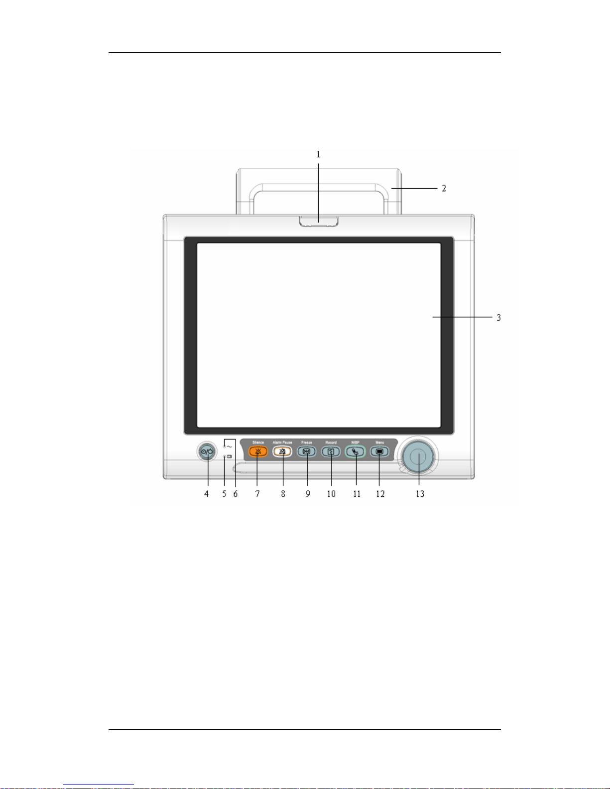
2.2.1 Front View
1. Alarm lamp
When a physiological or technical alarm occurs, this lamp will flash as defined below.
High level alarms: the lamp flashes quickly in red.
Medium level alarms: the lamp flashes slowly in yellow.
Low level alarms: the lamp lights yellow without flashing.
2. Handle
3. Display Screen
Page 25

2-3
4. Power On/Off Switch
Press this switch to turn the patient monitor on. Press it again and hold for 2 seconds to
turn the patient monitor off. An indicator is built in this switch. It turns on when the
patient monitor is on and turns off when the patient monitor is off.
5. Battery LED
On: when the battery is being charged or already fully charged.
Off: when no battery is installed or no AC source is connected.
Flashes: when the patient monitor operates on battery power.
6. AC power LED
It turns on when AC power is connected.
7.
Press to silence or restore all alarm sounds or clear alarms.
8.
Press to pause or restore alarms.
9.
Press to freeze or unfreeze waveforms.
10.
Press to start or stop recordings.
11.
Press to start or stop NIBP measurements.
12.
If no menu is displayed on the screen, pressing it will enter the main menu. If there is a
menu displayed on the screen, pressing it will close that menu.
13. Knob
Rotate the Knob clockwise or anti-clockwise. With each click, the highlight jumps to
the neighboring item. When you reach your desired item, press the Knob to select it.
Page 26
2-4
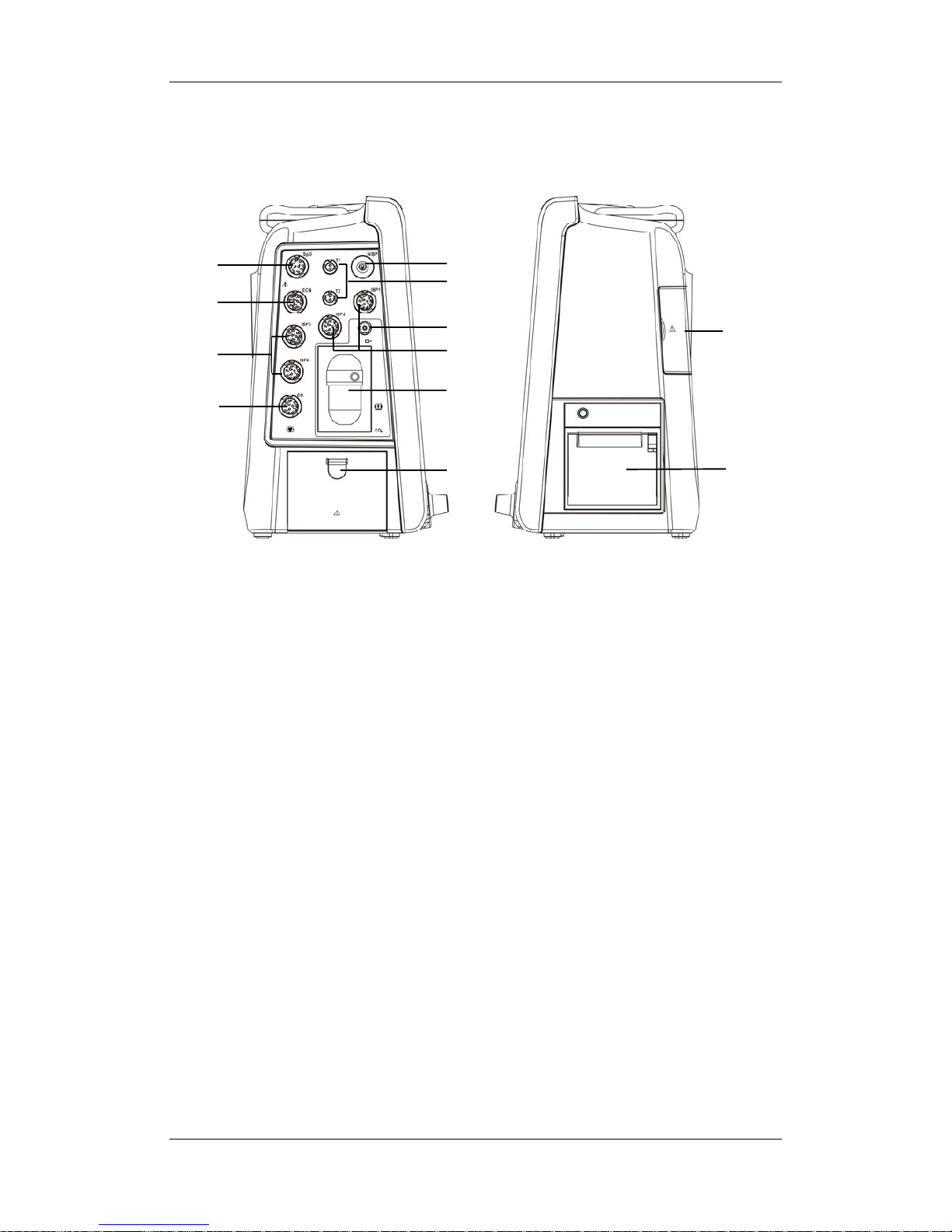
2.2.2 Side View
1. SpO
2
connector
2. ECG connector
3. IBP connector (four channels)
4. C.O. connector
5. NIBP connector
6. Temp connector (double channels)
7. Exhaust gas outlet of CO
2
module or AG module
8. Watertrap connector (sidestream CO
2
module or AG module)
This connector is also optional for microstream or mainstream CO
2
module.
9. Battery door
10. CF storage card slot cover
11. Recorder
1
2
4
6
5
7
3
9
3
10
11
8
Page 27
2-5
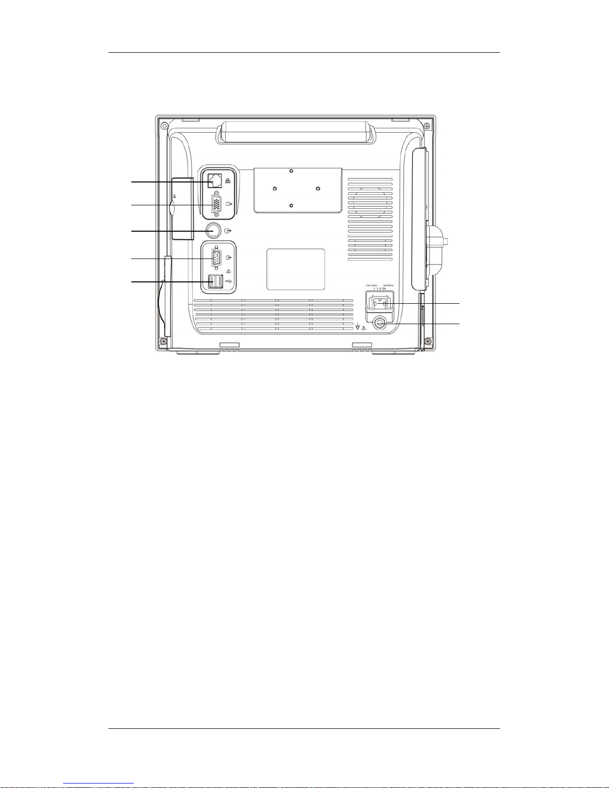
2.2.3 Rear View
1. Network Connector
It is a standard RJ45 connector, through which the patient monitor can be networked.
2. Video Connector
It connects a standard VGA color monitor, which extends the display capability of
your monitor. The contents displayed on the secondary display screen accord with
those displayed on the monitor screen.
3. Auxiliary Output
It is a standard BNC connector, through which analog signals, alarm signals or
synchronization signals can be outputted, depending on how your monitor is
configured.
4. RS232 serial port
It is a DB9 connector, used to connect a PC for data or a compatible device, and
supports DIAP communication protocol.
5. USB Connectors
They connect external storage devices.
6. AC Power Input
7. Equipotential Grounding Terminal
When the patient monitor and other devices are to be used together, their equipotential
grounding terminals should be connected together, eliminating the potential difference
between them.
1
2
3
4
5
6
7
Page 28
2-6
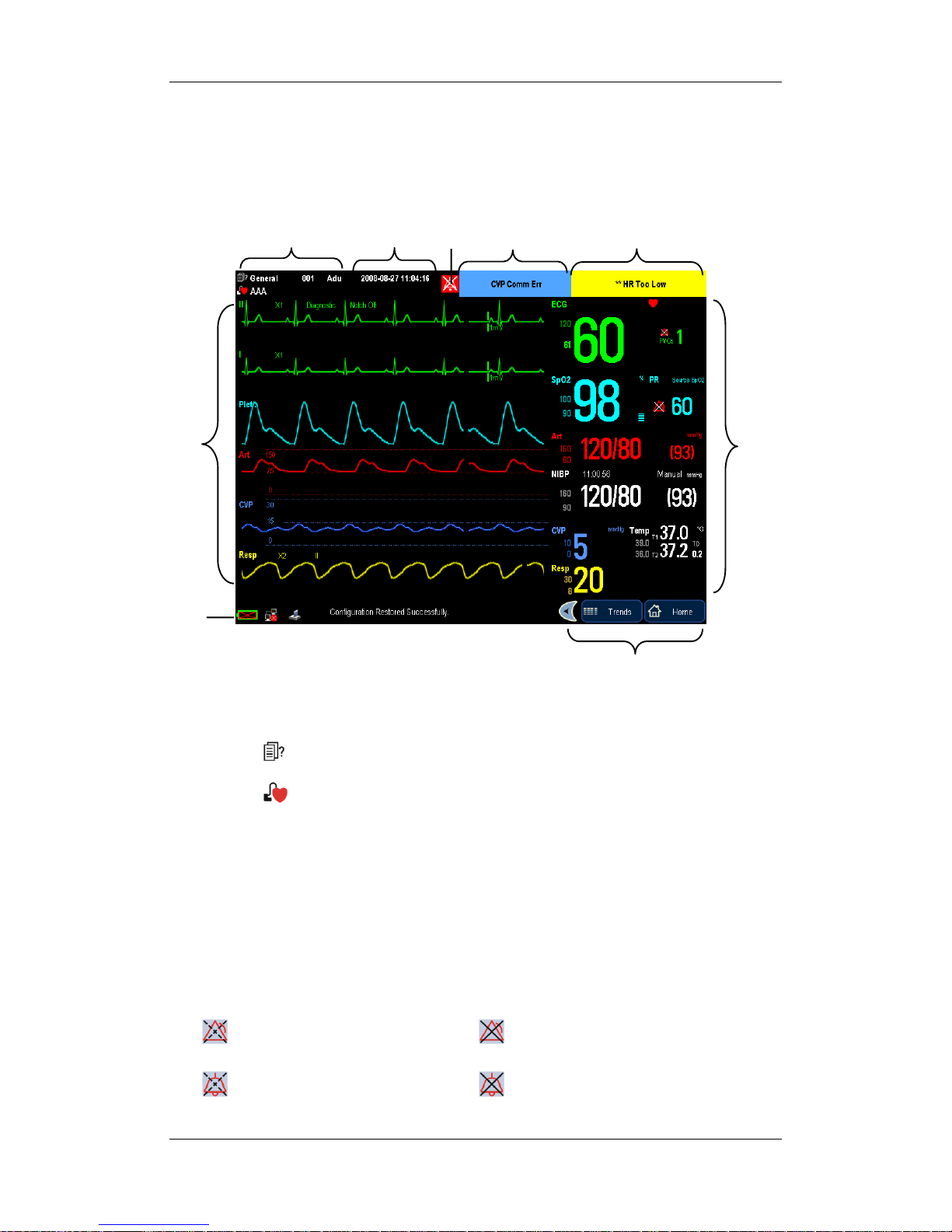
2.3 Display Screen
This patient monitor adopts a high-resolution TFT LCD to display patient parameters and
waveforms. A typical display screen is shown below.
1. Patient Information Area
This area shows the patient information such as department, bed number, patient name,
patient category and paced status.
: indicates that no patient is admitted or the patient information is incomplete.
: indicates that the patient has a pacer.
If no patient is admitted, selecting this area will enter the [Patient Setup] menu. If a
patient has been admitted, selecting this area will enter the [Patient Demographics]
menu.
2. Date and Time
This area shows the system time of the patient monitor. By selecting this area, you can
enter the [System Time] setup menu.
3.Alarm Symbols
indicates alarms are paused. indicates alarms are turned off.
indicates alarm sounds are silenced. indicates alarm sounds are turned off.
1
3
45
9
2
6
7
8
Page 29

2-7
4. Technical Alarm Area
This area shows technical alarm messages and prompt messages. When multiple
messages come, they will be displayed circularly. Select this area and the technical
alarm list will be displayed.
5. Physiological Alarm Area
This area shows physiological alarm messages. When multiple alarms occur, they will
be displayed circularly. Select this area and the physiological alarm list will be
displayed.
6. Waveform Area
This area shows measurement waveforms. The waveform name is displayed at the
upper left corner of the waveform. Select this area and the corresponding waveform
setup menu will be displayed.
7. Parameter Area
This area shows measurement parameters. Each monitored parameter has a parameter
window and the parameter name is displayed at the upper left corner. When this area
cannot accommodate all parameters, the excess parameters will automatically occupy
the waveform area from bottom to top. Select this area and the corresponding
measurement setup menu will be displayed.
8. Prompt Message Area
This area shows the prompt messages, network status icons, battery status icons, etc.
For details about battery status symbols, refer to the chapter Batteries.
indicates the patient monitor is connected to a wired network successfully.
indicates the wireless function is working.
indicates the patient monitor has failed to connect a wired network.
indicates the wireless function is not working.
indicates a CF storage card is inserted.
indicates an USB storage card is inserted.
9. QuickKeys Area
This area contains QuickKeys that give you fast access to functions.
Page 30
2-8
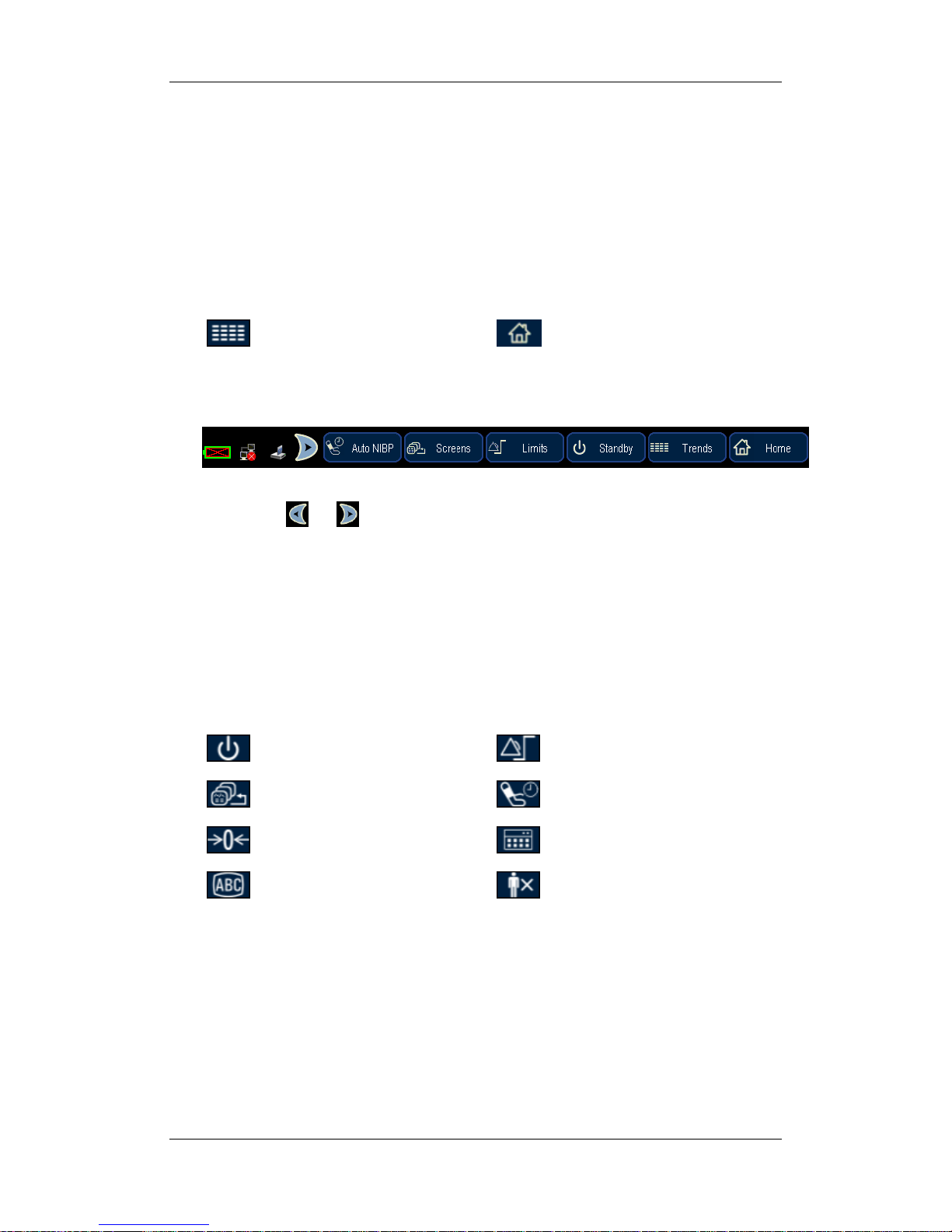
2.4 QuickKeys
A QuickKey is a configurable graphical key, located at the bottom of the main screen. They
give you fast access to functions. Their availability and the order in which they appear on
your screen, depend on how your patient monitor is configured.
By default, there are two QuickKeys that remain on the screen all the time to give you fast
access to functions.
Review tabular trends
Return to the main screen
Besides, you can have four more QuickKeys as shown below.
By selecting
or , you can unfold or fold the four QuickKeys. When there is no
operation on the four QuickKeys for 15 seconds after they are unfolded, they will be folded
automatically. Besides, you can set the four QuickKeys in configuration mode:
1. Enter the configuration mode. Select [Others] in either configuration.
2. In the [Select QuickKeys] area, select your desired QuickKeys 1-4.
3. Save the configuration.
The following QuickKeys can be selected:
Enter standby mode
Alarm Limits Setup
Change screen
Start Auto NIBP measurement
Zero IBP
Perform calculations
Mark Event
Discharge a Patient
Page 31

3-1
3 Basic Operations
3.1 Installation
WARNING
z The equipment shall be installed by personnel authorized by Mindray.
z The software copyright of the equipment is solely owned by Mindray. No
organization or individual shall resort to juggling, copying, or exchanging it or to
any other infringement on it in any form or by any means without due permission.
z Devices connected to the equipment must meet the requirements of the applicable
IEC standards (e.g. IEC 60950 safety standards for information technology
equipment and IEC 60601-1 safety standards for medical electrical equipment).
The system configuration must meet the requirements of the IEC 60601-1-1
medical electrical systems standard. Any personnel who connect devices to the
equipment’s signal input/output port is responsible for providing evidence that the
safety certification of the devices has been performed in accordance to the IEC
60601-1-1.If you have any question, please contact us.
z If it is not evident from the equipment specifications whether a particular
combination is hazardous, for example, due to summation of leakage currents,
consult the manufacturers or else an expert in the field, to ensure the necessary
safety of all devices concerned will not be impaired by the proposed combination.
z Combinations of medical equipment with non-medical equipment must comply
with IEC 60601-1-1. Never use a multiple portable socket-outlet or extension cord
when combining equipment unless the socket outlet is supplied specifically for use
with that equipment.
Page 32

3-2
3.1.1 Unpacking and Checking
Before unpacking, examine the packing case carefully for signs of damage. If any damage is
detected, contact the carrier or us. If the packing case is intact, open the package and remove
the equipment and accessories carefully. Check all materials against the packing list and
check for any mechanical damage. Contact us in case of any problem.
NOTE
z Save the packing case and packaging material as they can be used if the equipment
must be reshipped.
WARNING
z When disposing of the packaging material, be sure to observe the applicable waste
control regulations and keep it out of children’s reach.
z The equipment might be contaminated during storage and transport. Before use,
please verify whether the packages are intact, especially the packages of single use
accessories. In case of any damage, do not apply it to patients.
3.1.2 Environmental Requirements
The operating environment of the equipment must meet the requirements specified in this
manual.
The environment where the equipment is used shall be reasonably free from noises, vibration,
dust, corrosive, flammable and explosive substances. If the equipment is installed in a cabinet,
sufficient space in front and behind shall be left for convenient operation, maintenance and
repair. Moreover, to maintain good ventilation, the equipment shall be at least 2 inches (5cm)
away from around the cabinet.
When the equipment is moved from one place to another, condensation may occur as a result
of temperature or humidity difference. In this case, never start the system before the
condensation disappears.
WARNING
z Make sure that the operating environment of the equipment meets the specific
requirements. Otherwise unexpected consequences, e.g. damage to the equipment,
could result.
Page 33

3-3
3.2 Getting Started
3.2.1 Inspecting the Monitor
1. Before you start to make measurements, check the patient monitor for any mechanical
damage and make sure that all external cables, plug-ins and accessories are properly
connected.
2. Plug the power cord into the AC power source. If you run the patient monitor on battery
power, ensure that the battery is sufficiently charged.
3. Check all functions you need to monitor your patient, and ensure that the monitor is in
good working order.
3.2.2 Switching On
After the inspection is finished, you can switch on the monitor:
1. Press the power on/off switch on the monitor’s front. The monitor performs a self test.
The system gives a beep, and at the same time, the alarm lamp turns yellow and then red.
The start-up screen is displayed.
2. The monitor enters the main screen.
3.2.3 Starting Monitoring
1. Check that the patient cables and sensors are correctly connected.
2. Check that the patient settings such as [Patient Cat.], [Paced], etc, are appropriate for
your patient.
3. Refer to corresponding measurement sections for details of how to perform the
measurements you want to make.
WARNING
z Do not use the patient monitor for any monitoring procedure on a patient if you
suspect it is not working properly, or if it is mechanically damaged. Contact your
service personnel or us.
Page 34

3-4
3.3 Disconnecting from Power
To disconnect the patient monitor from the AC power source, follow this procedure:
1. Disconnect the patient cables and sensors from the patient.
2. Press and hold the power on/off switch for above 2 seconds. The patient monitor shuts
down and you can unplug the power cable.
CAUTION
z Although not recommended, you can press and hold the power on/off switch for 4
seconds to forcibly shut down the monitor when it could not be shut down
normally or under some special situations. This may cause loss of data of the
patient monitor.
3.4 Operating and Navigating
3.4.1 Using the Knob
Rotate the Knob clockwise or counter-clockwise. With each click, the highlight jumps to the
neighboring item. When you reach your desired item, press the Knob to select it.
When you rotate the knob, a cursor moves across the screen, following the direction of the
knob. You can position the cursor by rotating the knob so as to perform the desired operation.
Page 35

3-5
3.4.2 Using Keys
The monitor has three types of keys:
Softkey: A softkey is a graphic key on the screen, giving you fast access to certain
menus or functions. The monitor has three types of softkeys:
Waveform keys: Each waveform area can be seen as a softkey. You can enter a
waveform setup menu by selecting its corresponding waveform area.
Parameter keys: Each parameter area can be seen as a softkey. You can enter a
parameter setup menu by selecting its corresponding parameter area.
QuickKeys: QuickKeys are configurable graphical keys, located at the bottom of
the main screen. For details, refer to the section QuickKeys.
Hardkeys: A hardkey is a physical key on a monitoring device, such as the main menu
hardkey on the monitor’s front.
Pop-Up Keys: Pop-up keys are task-related keys that appear automatically on the
monitor screen when required. For example, the confirm pop-up key appears only when
you need to confirm a change.
3.4.3 Using the Touchscreen
Select screen items by pressing them directly on the patient monitor’s screen.
You can enable or disable touchscreen operations by pressing and holding the [Home]
QuickKey at the lower right corner of the screen for 3 seconds. A red padlock symbol is
displayed if touchscreen operations are disabled.
3.4.4 Using the On-Screen Keyboard
The on-screen keyboard enables you to enter information. Use the [Back] key to delete the
previously entered character. Use the [Caps] to toggle between uppercase and lowercase
letters. Select [Enter] to confirm what you have entered and close the on-screen keyboard.
Page 36

3-6
3.4.5 Using the Main Menu
To enter the main menu, select the hardkey on the monitor’s front. Most of monitor
operations and settings can be performed through the main menu.
Other menus are similar to the main menu and contain the following parts:
1. Heading: gives a sum-up for the current menu.
2. Main body: displays options, buttons, prompt messages, etc. The menu button with
“>>’’ enlarges a secondary window to reveal more options or information.
3. Online help area: displays help information for the highlighted menu item.
4. Confirm button area: accommodates confirm buttons such as [Previous Menu], [Ok],
[Exit], [Cancel], etc., which allows you to confirm menu operations.
1
2
3
4
Page 37

3-7
3.5 Operating Modes
Your monitor has four operating modes. Some are password protected.
Monitoring Mode:
This is the normal, every day working mode that you use for monitoring patients. You can
change elements such as alarm limits, parameter units and so forth. When you discharge the
patient, these elements return to their default values.
Configuration Mode:
Password protected, this mode is for clinical professionals in configuration tasks. For details,
refer to the Managing Configuration section.
Maintenance Mode:
Password protected, this is for professional service personnel in the tasks of maintenance,
repair, basic information setup and calibration.
Demonstration Mode:
Password protected, this is for demonstration purposes only.
Standby Mode:
Standby mode can be used when you want to temporarily interrupt monitoring.
To enter standby mode,
unfold the QuickKeys area to select the [Standby] QuickKey, or
select [Standby] when you want to discharge a patient. The monitor enters the standby
mode after discharging the current patient.
Standby suspends patient monitoring. All waves and numerics disappear from the display but
all settings and patient data information are retained. A standby screen is displayed.
To exit the standby mode, click anywhere on the screen or press any key. You can select [Yes]
or [No] from the popup dialog box.
[Yes]: The monitor enters the monitoring mode after discharging the current patient or
clearing the current patient’s data.
[No]: The monitor enters the monitoring mode and continues monitoring the current
patient.
Page 38

3-8
3.6 Using an External Storage Device
An external storage device is used to prevent data loss in case of a sudden power failure. The
patient data such as trend data, waveform data, etc., will be automatically saved into the
external storage device during patient monitoring. In case of a sudden power failure, the
patient data can be retrieved from the external storage device after the patient monitor restarts.
So far only CF storage card is supported.
CF storage card can also be used to transfer patient data. USB storage card can be used to
transfer monitor configuration. Please refer to the corresponding sections for details.
To insert a CF storage card, open the compartment and then insert the card until the button
flips out.
To remove the CF storage card, follow this procedure:
1. In the main menu, select [Unload CF Storage Card].
2. Select [Ok] from the popup menu to unload the CF storage card. A status message
shown in the prompt message area will report completion of the unloading.
3. Press the button until the CF storage card flips out.
To browse the data saved in the CF storage card, follow this procedure:
1. In the main menu, select [Archives >>].
If the [Archives Access] is set as [Direct], you can directly enter into the [Patient
Data] menu.
If the [Archives Access] is set as [Password], you need a password to enter into
the [Patient Data] menu. This password is the same as the one for entering the
configuration mode.
2. Select [History Data >>]. Select a patient whose data you want to view from the
[Patient Data List] and then select [Review].
3. In the [Review] menu, select the data you want to review.
The monitor allows only the history data saved in the CF storage card to be reviewed so far.
As reviewing the history patient’s data is just like reviewing the current patient’s data, you
can refer to the chapter Review for details.
Page 39

3-9
NOTE
z Data may be unable to be saved into the CF storage card shortly after the card is
inserted.
z If no CF storage card is used or the card has been removed, all the data saved will
get lost in case that the monitor shuts down or a sudden power interrupt occurs.
z Admitting too many patients will affect the read-write speed of the CF storage
card. Please clear the patients’ data in time.
CAUTION
z Unload the CF storage card before removing it from the patient monitor.
Otherwise it may cause damage to the data in the card.
z Use only the CF storage card specified by Mindray.
3.7 Using an External Display
An external display, showing the same screen as the host display, can be connected to the
monitor through the video output connector, for viewing only.
The recommended specification is as below.
External display
Screen type Medical-grade VGA monitor
Resolution 800×600 pixels or above
EMC MPR II, CISPR 11B
Third certificate UL, C-UL, TUV, CE, FCC
3.8 Changing General Measurement Settings
This chapter covers only general measurement settings in monitoring mode. Other specific
measurement settings can be referred to in respective sections.
3.8.1 Switching On/Off Modules
You can switch on or off measurement modules as required.
In the main menu, select [Others>>]→ [Module Switch]. Select parameters for measuring,
and then select [Exit] to save the settings.
Page 40

3-10
3.8.2 Changing Measurement Settings
Each measurement has a setup menu in which you can adjust all of its settings. You can enter
a setup menu by selecting a certain measurement numeric. For example, by selecting the
ECG numeric, you can access the [ECG Setup] menu.
This menu displays numeric-related measurement settings, such as alarm limits, alarm switch
and so forth. You can set each measurement as required.
3.8.3 Changing Waveform Settings
Accessing the Waveform Setup Menu
Each wave-related measurement has a waveform setup menu. You can enter a setup menu by
selecting a certain measurement waveform. This menu displays wave-related measurement
settings, such as gain, wave speed and so forth. You can set each measurement’s waveform as
required.
For example, by selecting the Art wave, you can adjust its wave speed, scale and so forth in
the [Art Waveform] setup menu.
Changing a Wave Speed
In waveform setup menu for your desired measurement, select [Sweep] and then select the
appropriate setting. Lowering the wave speed compresses the wave and lets you view a
longer time period. Increasing the speed expands the waveform, giving you a more detailed
view.
3.9 Changing General Settings
General settings refer to the settings regarding how the monitor works, e.g. alarm volume,
brightness and so forth. Most general settings can be carried out in configuration mode. This
chapter covers some general settings that can be carried out in monitoring or maintenance
mode.
Page 41

3-11
3.9.1 Setting up a Monitor
In situations where you install a patient monitor or change the patient monitor’s application
site, you need to setup the patient monitor as follows:
1. In the main menu, select [Maintenance >>] → [User Maintenance >>] → enter the
required password.
2. Select [Device Setup>>]. In the pop-up menu, select, in turn, [Monitor Name],
[Institution Name], [Department] and [Bed No.], and then change their settings.
3.9.2 Changing Language
1. In the main menu, select [Maintenance >>]→[User Maintenance >>]→enter the
required password and then select [Device Setup >>].
2. In the [Device Setup] menu, select [Language] and then select the desired language.
3. Restart the patient monitor.
3.9.3 Setting DIAP Baud Rate
1. In the main menu, select [Maintenance >>]→[User Maintenance >>]→enter the
required password and then select [Device Setup >>].
2. Select [DIAP Baud Rate] and then select the desired baud rate.
WARNING
z When connecting compatible devices to the patient monitor via RS232 serial port,
make sure the baud rate of the compatible devices is consistent with that of the
patient monitor. Otherwise, the compatible devices can’t communicate with the
patient monitor.
3.9.4 Adjusting the Screen Brightness
1. In the main menu, select [Others >>].
2. Select [Brightness].Select the appropriate setting for the screen brightness. 10 is the
brightest, and 1 is the least bright. If the patient monitor operates on battery power, you
can set a less bright screen to prolong the operating time of the battery.
Page 42

3-12
3.9.5 Setting the Date and Time
1. In the main menu, select [Maintenance >>] → [System Time>>].
2. Set [Year], [Month], [Day], [Hour], [Minute] and [Second].
To set the date format and the time format,
1. In the main menu, select [Maintenance >>]→[User Maintenance >>]→enter the
required password and then select [Device Setup >>].
2. Select [Date Format] and toggle between [yyyy-mm-dd], [mm-dd-yyyy] and
[dd-mm-yyyy].
3. Select [Time Format] and toggle between [24h] and [12h].
WARNING
z When connecting compatible devices to the patient monitor via RS232 serial port,
make sure that the baud rate of the compatible devices is consistent with that of the
patient monitor. Otherwise, the compatible devices fail to communicate with the
patient monitor properly.
Page 43

3-13
3.9.6 Adjusting Volume
Alarm Volume
1. In the main menu, select [Alarm Setup >>].
2. Select the appropriate volume from [Alm Volume]: X-10, in which X is the minimum
volume, depending on the set minimum alarm volume (refer to the chapter Alarm), and
10 the maximum volume.
Key Volume
1. In the main menu, select [Others >>].
2. Select [Key Volume] and then select the appropriate volume.0 means off, and 10 the
maximum volume.
QRS Volume
The QRS tone is derived from either the HR or PR, depending on which is currently selected
as the alarm source in the ECG setup menu.When monitoring SpO
2
, there is a variable pitch
tone which changes as the patient’s saturation level changes. The pitch of the tone rises as the
saturation level increases and falls as the saturation level decreases. The volume of this tone
is user adjustable. Take PR as an example, to adjust QRS volume,
1. Select the PR parameter window. you can access the [PR Setup] menu.
2. Select [Beat Vol] and then select the appropriate volume. 0 means off, and 10 the
maximum volume.
Page 44

3-14
FOR YOUR NOTES
Page 45

4-1
4 Managing Patients
4.1 Admitting a Patient
The patient monitor displays physiological data and stores them in the trends as soon as a
patient is connected. This allows you to monitor a patient that is not admitted yet. However, it
is recommended that you fully admit a patient so that you can clearly identify your patient, on
recordings, reports and networked devices.
If the patient monitor already admits a patient, it is recommended to discharge this patient
before admitting a new patient. Otherwise, the new patient’s data will be stored into that
patient’s data.
To admit a patient:
1. In the main menu, select [Patient Setup >>].
2. Select [Admit Patient]. If there is a patient currently in your monitor, select [Ok] from
the popup menu to discharge the current patient. Otherwise, select either:
[Yes] to apply the data in your patient monitor to the new patient, or
[No] to clear any previous patient data.
3. In the [Patient Demographics] menu, enter the demographic details, of which:
[Patient Cat.] determines the way your patient monitor processes and calculates
some measurements, and what safety and alarm limits apply for your patient.
[Paced] determines whether to show pace pulse marks on the ECG waveform.
When the
[Paced] is set to [No], pace pulse marks are not shown in the ECG
waveform.
4. Select [Ok].
Page 46

4-2
WARNING
z [Patient Cat.] and [Paced] will always contain a value, regardless of whether the
patient is fully admitted or not. If you do not specify settings for these fields, the
patient monitor uses the default settings from the current configuration, which
might not be correct for your patient.
z For paced patients, you must set [Paced] to [Yes]. If it is incorrectly set to [No], the
patient monitor could mistake a pace pulse for a QRS and fail to alarm when the
ECG signal is too weak.
z For non-paced patients, you must set [Paced] to [No].If it is incorrectly set to [Yes],
the patient monitor may be unable to detect premature ventricular beats (including
PVCs) and perform ST segment analysis.
4.2 Editing Patient Information
To edit the patient information after a patient has been admitted, or when the patient
information is incomplete, or when you want to change the patient information:
1. In the main menu, select [Patient Setup >>].
2. Select [Patient Demographics] and then make the required changes.
3. Select [Ok].
4.3 Discharging a Patient
To discharge a patient:
1. In the main menu, select [Patient Setup >>].
2. Select [Discharge Patient] or [Clear Patient Data]. In the popup menu, you can:
Directly select [Ok] to discharge the current patient, or
Select [Standby] then [Ok]. The patient monitor enters the standby mode after
discharging the current patient, or
Select [Cancel] to exit without discharging the patient.
3. If a printer is connected to your patient monitor, you can select [Print End Case Report]
to print all contents that you are setting up to print as an End Case report before
discharging the patient. After printing is completed, the patient monitor will
automatically enter the standby mode or return to the main screen, depending on your
previous setting.
Page 47

4-3
NOTE
z Discharging a patient clears all history data in the monitor.
4.4 Switching between Wire and Wireless Networks
To switch between wire and wireless networks:
1. In the main menu, select [Maintenance >>]→ [User Maintenance >>].
2. Enter the required password.
3. In the user maintenance menu, select [Network Setup]
4. In the network setup menu, select the [Network Type] drop-down box and then toggle
between [Wire] and [Wireless].
NOTE
z If the [Network Type] option is grey, it indicates your monitor is not configured
with a wireless network card. You cannot switch to the wireless network.
4.5 Transferring Patient Data
You can transfer patient data between monitors with a CF storage card without re-entering the
patient demographic information. Transferring of patient data enables you to understand the
patient’s history condition. The patient data that can be transferred includes: patient
demographics, trend data, alarm events and parameters alarm limits.
To transfer the current patient data from the source monitor to the CF storage card:
1. In the main menu, select [Patient Setup >>].
2. Select [Transfer Patient Data]. Then select [Ok] in the popup menu to transfer patient
data and unload the CF storage card.
3. Remove the card after the message [CF Storage Card Unloaded Successfully]
displays.
To transfer the patient data from the CF storage card to the receiving monitor:
1. Insert the card into the receiving monitor.
Page 48

4-4
2. In the popup [Transfer Patient Data] menu, you can:
Select [Transfer Patient] to transfer the patient data to the monitor, or
Select [Cancel Transfer] to cancel the operation of transferring patient data. Then
the patient data to be transferred becomes archived patient data. The current patient
data starts to be saved in the card.
Select [Unload CF Storage Card] to not transfer the patient data and to unload the
card. The current patient data will not be saved in the card.
3. When you select [Transfer Patient], the monitor compares the patient information stored
in both the CF storage card and the monitor and deals with the patient data based on the
following.
Different
Patients:
The monitor erases all the current patient data, transfers the patient
data from the CF storage card, and loads the configuration according
to the patient category.
Same
Patient:
In the popup dialog box, you can:
Select [Yes] to merge the patient data in the monitor and CF storage
card.
Select [No] to erase all the current patient data in the monitor and to
transfer the patient data from the CF storage card.
Please notice that only the patient data in the past specified number of hours can be
transferred from the CF storage card. The number of hours is called [Transferred Data
Length] and can be specified in the configuration mode. If the latest patient data stored on
the card has a time stamp newer than the time displayed on the receiving monitor, data
transfer will be prohibited.
WARNING
z After a patient is successfully transferred, check if the patient settings (especially
patient category, paced status and alarm limits settings, etc.) on the monitor are
appropriate for this patient.
Page 49

4-5
4.6 Connecting to a Central Monitoring System
If your patient monitor is connected to a central monitoring system (CMS):
1. All patient information, measurement data and settings on the patient monitor can be
transferred to the CMS.
2. All patient information, measurement data and settings can be displayed simultaneously
on the patient monitor and CMS. For some functions such as editing patient information,
admitting a patient, discharging a patient, starting/stopping NIBP measurements, etc.,
bi-directional control can be achieved between your patient monitor and the CMS.
For details, refer to the CMS’s instructions for use.
Page 50

4-6
FOR YOUR NOTES
Page 51

5-1
5 Managing Configurations
5.1 Introduction
When performing continuous monitoring on a patient, the clinical professional often needs
to adjust the monitor’s settings according to the patient’s condition. The collection of all
these settings is called a configuration. Allowing you to configure the monitor more
efficiently, the monitor offers different sets of configuration to suit different patient
categories and departments. You can change some settings from a certain set of
configuration and then save the changed configuration as a user configuration.
The default configurations provided for your monitor are department-oriented. You can
choose either from:
General
OR
ICU
NICU
CCU
Each department has three different sets of configurations tailored for adult, pediatric and
neonatal patients.
WARNING
z The configuration management function is password protected. The configuration
management tasks must be performed by clinical professionals.
The system configuration items can be classified as:
Global configuration items
These items can affect all the monitor settings. Most global configuration items, such as
monitor name, system time, etc., can be set in maintenance mode. The global configuration
items that need to be set in configuration mode include default patient category, whether to
load the selected configuration at startup, etc., which are usually displayed on the system
configuration-main screen.
Parameter configuration items
These items relates to parameters, e.g., waveform gain, alarm switch, alarm limits..
Page 52

5-2
Conventional configuration items
These items define how the monitor works, e.g., screen layout, record, print and alarm
settings.
For all the configuration items and their default values, see appendix Configuration Default
Information.
5.2 Entering and Exiting the Configuration Mode
To enter the configuration mode,
1. Press the
hardkey on the monitor’s front to enter the main menu.
2. Select [Manage Configuration >>] → [Configuration >>]. Enter the required
password and then select [Ok].
To exit the configuration mode,
1. Select [Exit] in the system configuration-main screen.
2. Then select [Ok] from the popup dialog box. The monitor will restart and the modified
configuration will take effect afterwards.
Page 53
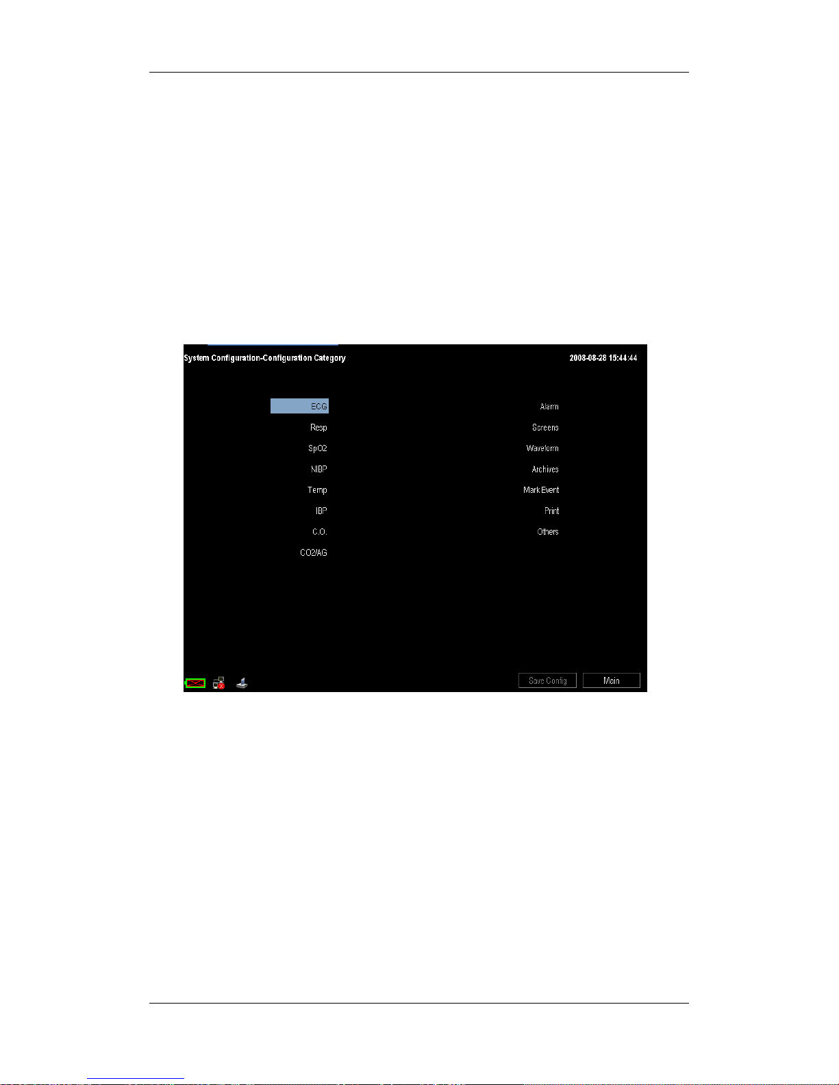
5-3
5.3 Viewing and Changing Configurations
In configuration mode, you can view, change and save all the configuration items for each
department.
1. After entering the configuration mode, verify that the current department is the one you
desire.
2. In the system configuration-main screen, select the desired configuration and then
select [View Config.].
3. As shown below, in the configuration category menu, you can view all the parameters
and conventional configuration items.
4. Select to enter a certain configuration category, e.g. ECG, then you can view all the
related configuration items by selecting [Prev Page] or [Next Page] and change them
if necessary.
5. After the change is done, select [Save Config.] to save the changed configuration. If
you have made some changes when viewing the default configuration of a certain
department, you can specify a name in the popup name configuration window to save
the changed configuration.
If the current department configuration is not the one you want to view, you can select
[Change Department >>] in the system configuration-main screen and then choose the one
you want for viewing as shown below. After returning to the main screen, you can still view
and change the configuration following the above steps.
Page 54

5-4
NOTE
z Changing the department will delete all the saved user configurations
automatically. Please act with caution.
5.4 Adding a Configuration
You can change monitor settings as required and then save the changed settings into a user
configuration. You can specify a name for the saved user configuration. The monitor can
save up to 3 sets of user configuration for the current department.
1. Select [Add Config.] in the system configuration-main screen.
2. In the load configuration menu, select a configuration as template.
[Defaults]: factory default configurations for each department.
user customized configuration: already saved user configuration
[Latest Settings under Monitor Mode]: If you have changed some settings
before entering the configuration mode, you can import these settings to your
newly added user configuration by selecting [Latest Settings under Monitor
Mode].
3. Enter a name and then select [Ok].
4. Change the settings if necessary and make sure that the settings are appropriate for
your patient.
5. After the change is done, select [Save Config.] or [Main] and then [Ok].
5.5 Deleting a Configuration
You can delete an already saved user configuration.
1. Select [Delete Config.] in the system configuration-main screen.
Page 55

5-5
2. In the select user configuration menu, select the user configurations you want to delete
and then select [Ok].
3. Select [Ok] in the popup dialog box.
5.6 Loading a Configuration
You may make changes to some settings during operation. However, these changes or the
pre-selected configuration may not be appropriate for the newly admitted patient. Therefore,
the monitor allows you to load aother user configuration of the current department under
monitoring mode so as to ensure that all the settings are appropriate for your patient.
To load a configuration,
1. In monitoring mode, select [Manage Configuration >>] from the main menu.
2. Select the default configuration or a certain user configuration according to the
patient’s condition.
3. Select [Ok].
NOTE
z In monitoring mode, only the default configuration of the current department or
the already saved user configuration can be loaded. You can only change the
department in configuration mode.
5.7 Setting Default Configuration at Startup
When the monitor restarts after quitting for over 120 seconds, it will load the pre-set default
configuration to restore the system configuration. The default configuration can be the latest
configuration, or a factory default configuration or user configuration.
Page 56

5-6
To set the default configuration at startup,
1. Enter the configuration mode.
2. In the load configuration area, select a factory default configuration of the current
department or a user configuration as the default configuration.
3. Select [Adu] or [Ped] or [Neo] from the [Patient Cat.] as the default patient category.
4. You can change the department by selecting [Change Department >>]. But this will
delete all the saved user configurations.
5. Set the [Load Selected Config at Startup] option:
Selected: When the monitor restarts after quitting for over 120 seconds, it will
load the configuration you have selected in the load configuration area.
Deselected: The monitor will load the latest configuration at startup no matter
how long it has been quitted.
NOTE
z To find out which configuration has been loaded when the monitor starts, check
the message (lasting for about 10 seconds) displayed at the bottom of the screen
after the main screen comes out.
5.8 Loading the Latest Configuration Automatically
During operation, you may make changes to some settings. These changes may not be saved
as user configuration. To prevent the changes from loss in case of a sudden power failure,
the monitor stores the configuration in real time. The stored configuration is the latest
configuration.
If [Load Selected Config. at Startup] is selected, the monitor will load the latest
configuration if restarts within 60 seconds after the power failure. And it will load the
default configuration rather than the latest configuration if restarts 120 seconds later after
the power failure. The monitor may load either the latest configuration or the default
configuration if restarts from 60 to 120 seconds after the power failure.
If [Load Selected Config. at Startup] is not selected, the monitor will load the latest
configuration at startup.
Page 57

5-7
5.9 Transferring a Configuration
When installing several monitors with identical user configuration it is not necessary to set
each unit separately. An USB storage card may be used to transfer the configuration from
monitor to monitor.
To export the current monitor’s configuration:
1. Insert the USB storage card into the monitor’s USB port.
2. Select [Transfer Config.] in the system configuration-main screen.
3. Select [Export Config.>>] in the transfer config menu and then select [Ok] in the
popup dialog box. A status message will report completion of the transfer.
To import the configuration in the card to the monitor:
1. Insert the USB storage card into the monitor’s USB port.
2. Select [Transfer Config.] in the system configuration-main screen.
3. Select [Import Config.>>] in the transfer config menu and then select [Ok] in the
popup dialog box. A status message will report completion of the transfer.
Page 58

5-8
FOR YOUR NOTES
Page 59

6-1
6 User Screens
6.1 Tailoring Your Screens
You can tailor your patient monitor’s screens by setting:
Waveform sweep mode
Wave line size
The way to draw waves
The color in which each measurement’s numerics and waveform are displayed
The waveforms to be displayed and their display order.
Some settings can be changed manually in monitoring mode. For details about
configuration mode, refer to the Managing Configuration chapter.
6.1.1 Setting the Waveform Sweep Mode
1. In the main menu, select [Others >>] or select [Waveform] in configuration mode.
2. Select [Sweep Mode] and toggle between [Refresh] and [Scroll].
[Refresh]: The waveforms keep stationary, being refreshed from left to right by a
moving “erase bar”.
[Scroll]: The waveforms move from the right to the left with time passing by.
6.1.2 Changing the Wave Line Size
1. Select [Waveform] in configuration mode.
2. Select [Wave Line] and toggle between [Thick], [Med] and [Thin].
6.1.3 Choosing the Way to Draw Waves
1. Select [Waveform] in configuration mode.
2. Select [Draw Wave] and then toggle between [Color] and [Mono]:
[Color]: The waveform is optimized by the system and appears smooth.
[Mono]: The waveform is unsmoothed.
Page 60

6-2
6.1.4 Changing Parameter and Waveform Colors
1. Select [Waveform] in configuration mode.
2. In the [Parameter/Wave Color] area, you can set color for each parameter and
waveform. Selecting [Next Page] allows you to set color for more parameters and
waveforms.
6.1.5 Selecting Waveforms for Display
Your can select waveforms for display on the screen:
1. In the main menu, select [Others >>]→[Wave Setup >>]→[Select Waves >>].
2. In the [Select Waves] menu, select the waveforms you want for display on the screen.
3. Select [Exit]. Your selections will take effect automatically.
Additionally, you can change the order the waveforms are displayed on the screen if needed.
1. In the main menu, select [Others >>]→[Wave Setup >>].
2. In the [Wave Sequence] menu, you can sequence the waveforms displayed on the
screen.
3. Select [Exit]. Your change will take effect automatically.
Select [Screens] in configuration mode, and you can also change the order in which all
waveforms are displayed on the all parameters screen.
6.1.6 Changing Screen Layout
1. In the main menu, select [Screen Layout >>].
2. Select a normal screen, such as all parameters screen, big numerics screen, etc.
3. You can also select a split-screen functional view if necessary, such as minitrends,
others, etc. But the functional view is available only with the all parameters screen.
You can select [Screens] in configuration mode and select your desired screen. Then, your
selected screen will be displayed when the configuration is applied.
Page 61

6-3
6.2 Viewing Minitrends
6.2.1 Having a Split-Screen View of Minitrends
You can split the all parameters screen so that one part of the screen, on the left hand side,
continuously shows graphic minitrends beside waveforms as shown in the figure below.
To have a split-screen view of minitrends, you can:
In the main menu, select [Screen Layout >>]→[Minitrends]→[Ok].
The split-screen view provides minitrends for multiple parameters. In each field, the label,
scale and time are respectively displayed at the top, left, and bottom as shown below.
Minitrend view
Page 62

6-4
6.2.2 Changing Minitrend Length
The minitrend length cannot be chosen for individual parameters. You can only change the
minitrend length for all parameters:
1. Select either parameter’s minitrend field.
2. In the [Minitrend Setup] menu, select [Minitrend Length] and then select your
desired setting.
3. Select [Exit]. Your change will take effect automatically.
6.2.3 Changing a Parameter for Viewing
You can also select your desired parameters to view their minitrends.
1. Select either parameter’s minitrend field.
2. In the [Minitrend Setup] menu, you can select your desired parameter from the select
parameter area. If you want to select other parameter, select [Other Parameters >>]
and then select your desired parameters.
3. Select [Ok].
Page 63

6-5
6.3 Viewing oxyCRG
To have a split screen view of oxyCRG, you can:
In the main menu, select [Screen Layout >>].
Select [oxyCRG]→[Ok].
The split-screen view covers the lower part of the waveform area and shows HR trend,
SpO
2
trend and RR trend (or Resp Wave). At the bottom, there are controls:
1. Trend length list box
In the trend length list box, you can select [1 min], [2 min], [4 min], or [8 min].
2 Resp Wave (or RR Trend) list box
From this list box, you can select either [Resp Wave] or [RR Trend] for display.
3. Record
Through this button, you can print out the currently displayed oxyCRG trends by the
recorder.
4. Exit
You can select it to exit the oxyCRG screen and return to the all parameters screen.
31 4
2
Page 64

6-6
6.4 Viewing Other Patients
6.4.1 Care Group
If your patient monitor is connected to a central monitoring system, you can select up to 8
bedside monitors into a Care Group. This lets you:
View information on the monitor screen from another bed in the same Care Group.
Be notified of physiological and technical alarm conditions at the other beds in the
same Care Group.
To have a Care Group:
1. Select [Screens] QuickKey or select [Screen Layout >>] in the main menu. Then,
select [Others] and [Ok] from the popup menu.
2. In the [View Other Patient] window, select the care group setup button.
3. Select the desired bedside monitors from the [Connected Monitor List], and then
select the [Exit] button.
6.4.2 Viewing the Care Group Overview Bar
The Care Group overview bar locates at the bottom of the [View Other Patient] window. In
the overview bar, the department and bed label for any Care Group beds are displayed. The
color in which a Care Group bed appears matches its status:
Red: indicates the bed is giving high-level physiological alarms.
Yellow: indicates the bed is giving medium- or low-level physiological alarms, or
medium-level technical alarms.
Blue: indicates the bed is giving low-level technical alarms.
Grey: indicates the bed fails to be networked (bright grey) or stays in the standby mode
(dark grey).
Black: indicates the bed is networked but gives no alarms.
When multiple alarms occur to a Care Group bed, the Care Group bed appears in the color
that matches the highest level alarm.
You can view a Care Group bed’s alarms by selecting it from the care group, and as well
you can select the [V iew This Patient] button to view this bed in the [View Other Patient]
window.
For more details about Care Group alarms, refer to the Alarms chapter.
Page 65

6-7
6.4.3 Understanding the View Other Patient Window
When you first open the [View Other Patient] window, the patient monitor automatically
selects a monitor from the network to display in the [View Other Patient] window.
The view other patient window covers the lower part of the waveform area and consists of:
1. Information Area: shows the patient information (including department, bed number,
patient name, etc.) and network status symbols.
2. View Area: shows physiological waveforms and parameters. You can switch a
waveform area to a parameter area by selecting your desired waveform area and then
selecting [Switch to Parameter Area], or switch a parameter area to a waveform area
by selecting your desired parameter area and then selecting [Switch to Waveform
Area].
3. Care Group Overview Bar.
4. Message Area: shows physiological and technical messages from the currently viewed
bed. By selecting this area, you can enter the [Alarm Information List] to view all
physiological and technical messages coming from the currently viewed bed.
5. Alarm Silence Control Button: allows you to control the currently viewed bed to enter
or exit the alarm silence status. For details, refer to the Alarms chapter.
6. Care Group Setup Button: allows you to enter the [Connected Monitor List] and
select monitors into your Care Group.
1
2
3
45 6
Page 66

6-8
Additionally, you can change a waveform or parameter for viewing.
To change a waveform for viewing, select the waveform segment where you want a
new waveform to appear and then select the waveform you want from the popup menu.
To change a parameter for viewing, select the parameter window where you want a
new parameter to appear and then select the parameter you want from the popup menu.
6.5 Understanding the Big Numerics Screen
To enter the big numerics screen:
1. In the main menu, select [Screen Layout >>].
2. Select [Big Numerics] and then [Ok].
You can select your desired parameters to display in this screen: select the [Para. Setup]
QuickKey and then select the parameters you want. For parameters having a waveform, the
waveform will also be displayed.
Page 67

7-1
7 Alarms
Alarms, triggered by a vital sign that appears abnormal or by technical problems of the
patient monitor, are indicated to the user by visual and audible alarm indications.
WARNING
z A potential hazard can exist if different alarm presets are used for the same or
similar equipment in any single area, e.g. an intensive care unit or cardiac
operating room.
z If your patient monitor is connected to a CMS, remote suspension, inhibition,
silence and reset of monitor alarms via the CMS may cause a potential hazard.
7.1 Alarm Categories
By nature, the patient monitor’s alarms can be classified into three categories: physiological
alarms, technical alarms and prompt messages.
1. Physiological alarms
Physiological alarms, also called patient status alarms, are triggered by a monitored
parameter value that violates set alarm limits or an abnormal patient condition.
Physiological alarm messages are displayed in the physiological alarm area.
2. Technical alarms
Technical alarms, also called system status alarms, are triggered by a device
malfunction or a patient data distortion due to improper operation or mechanical
problems. Technical alarm messages are displayed in the technical alarm area.
3. Prompt messages
As a matter of fact, prompt messages are not alarm messages. Apart from the
physiological and technical alarm messages, the patient monitor will show some
messages telling the system status. Messages of this kind are included into the prompt
message category and usually displayed in the prompt information area. But for some
measurements, their related prompt messages are displayed in their respective
parameter windows.
Page 68

7-2
7.2 Alarm Levels
By severity, the patient monitor’s alarms can be classified into three categories: high level,
medium level and low level.
Physiological alarms Technical alarms
High
level
Indicate that your patient is in a
life threatening situation, such
as Asystole, Vfib/Vtac and so
forth, and an emergency
treatment is demanded.
Indicate a severe device malfunction or an
improper operation, which could make it possible
that the monitor cannot detect critical patient status
and thus threaten the patient’s life, such as low
battery and so forth.
Medium
level
Indicate that your patient’s vital
signs appear abnormal and an
immediate treatment is
required.
Indicate a device malfunction or an improper
operation, such as ECG/SpO
2
lead off, which may
not threaten the patient’s life but may compromise
the monitoring of vital physiological parameters.
Low
level
Indicate that you patient’s vital
signs appear abnormal and an
immediate treatment may be
required.
Indicate a device malfunction or an improper
operation, which may compromise a certain
monitoring function but will not threaten the
patient’s life.
The level for some alarms, such as Asystole, Vfib/Vtac, etc., is predefined before the patient
monitor leaves the factory and cannot be changed. However, for most of the other
physiological alarms, alarm settings are user adjustable, e.g. alarm limits. For some
technical alarms, the alarm level is also user adjustable.
7.3 Alarm Indicators
When an alarm occurs, the patient monitor will indicate it to the user through visual or
audible alarm indications.
Alarm lamp
Alarm message
Flashing numeric
Audible alarm tones
Reminder tones
Page 69

7-3
7.3.1 Alarm Lamp
If an alarm occurs, the alarm lamp will flash. The flashing color and frequency match the
alarm level as follows:
High level alarms: the lamp flashes quickly in red.
Medium level alarms: the lamp flashes slowly in yellow.
Low level alarms: the lamp turns yellow without flashing.
7.3.2 Alarm Message
When an alarm occurs, an alarm message will appear in the technical or physiological alarm
area. For physiological alarms, the asterisk symbols (*) before the alarm message match the
alarm level as follows:
High level alarms: ***
Medium level alarms: **
Low level alarms: *
Additionally, the alarm message uses different background color to match the alarm level:
High level alarms: red
Medium level alarms: yellow
Low level physiological alarms: yellow
Low level technical alarms: light blue
You can view the alarm messages by selecting the physiological or technical alarm area.
7.3.3 Flashing Numeric
If an alarm triggered by an alarm limit violation occurs, the numeric of the measurement in
alarm will flash every second, and the corresponding alarm limit will also flash at the same
frequency indicating the high or low alarm limit is violated.
7.3.4 Audible Alarm Tones
The patient monitor uses different alarm tone patterns to match the alarm level:
High level alarms: triple+double+triple+double beep.
Medium level alarms: triple beep.
Low level alarms: single beep.
Page 70

7-4
NOTE
z When multiple alarms of different levels occur simultaneously, the patient monitor
will select the alarm of the highest level and give visual and audible alarm
indications accordingly.
7.3.5 Reminder Tones
When alarms are turned off or alarm tones are paused or turned off, the patient monitor will
give a single beep as the reminder tone in case of an active alarm condition. You can set the
reminder volume as [High], [Med] or [Low] in the [Alarm Setup] menu and set the
reminder interval as [1 min], [2 min] or [3 min] in configuration mode. You can only
switch on/off the reminder tone in configuration mode.
7.4 Understanding Alarm Statuses
You can set your monitor to one of the following four alarm statuses. The alarm symbols
match the alarm statuses as follows.
Alarms paused Alarms off
Alarm sound silenced Alarm sound off
7.4.1 Pausing Alarms
If you want to temporarily prevent alarms from sounding, you can pause alarms by pressing
the
hardkey on the monitor’s front.
No physiological alarm lamps flash and no alarms are sounded. No alarm messages are
shown.
No numeric and alarm limit flash.
The remaining pause time is displayed in the physiological alarm area.
For technical alarms, no alarms are sounded. The alarm lamps and alarm messages
remain active.
The
alarms paused symbol is displayed in the alarm status symbol area.
Page 71

7-5
When the alarm pause time expires, the alarm paused status is automatically cancelled and
the alarm tone will sound. You can also cancel the alarm paused status by pressing the
hardkey.
You can set the alarm pause time as desired in configuration mode. The default alarm pause
time is 2 minutes.
7.4.2 Switching Off Alarms
If you have set the alarm pause time as permanent, the monitor will enter the alarm off
status when you press the
hardkey. Besides the characteristics of the alarm pause status,
the alarm off status has the following characteristics.
[Alarm Off] is displayed in the physiological alarm area.
The
alarm off symbol is displayed in the alarm status symbol area.
You can cancel the alarm off status by pressing the
hardkey.
If a high level technical alarm, such as low battery, occurs, the alarm pause and alarm off
statuses are all automatically cancelled.
WARNING
z Pausing or switching off alarms may result in a hazard to the patient. Please be
very careful.
7.4.3 Silencing the Alarm Sound
You can silence all alarm sounds temporarily by pressing the hardkey on the monitor’s
front. In that case, the alarm lamps and alarm messages remain active and
appears in
the alarm status symbol area.
If the monitor switches to other alarm status or a new alarm occurs, the alarm sound
silenced status is automatically cancelled. You can also cancel the alarm sound silenced
status by pressing the
hardkey.
Page 72

7-6
7.4.4 Switching off Alarm Sound
In configuration mode, you can set the minimum alarm volume. The minimum alarm
volume refers to the minimum value you can set for the alarm volume.
When the alarm volume is set to 0, the monitor stays in alarm sound off status and a
symbol appears on the screen.
The alarm sound off status is cancelled and the alarm volume returns to the factory default
value automatically when:
The monitor shuts down and then restarts.
The monitor changes to other alarm status, such as alarms paused status or alarms off
status.
The alarm volume restores the default value after the monitor reloads the
configuration.
WARNING
z When the alarm sound is switched off, the patient monitor will give no audible
alarm tones even if a new alarm occurs. Therefore the user should be very careful
about whether to switch off the alarm sound or not.
7.5 Alarm Configuration
7.5.1 Alarm Tone Configuration
Changing the Alarm Volume
1. In the main menu, select [Alarm Setup >>].
2. Select the appropriate volume from [Alm Volume]: X-10, in which X is the minimum
volume, depending on the set minimum alarm volume, and 10 the maximum volume.
Setting the Alarm Tone Interval
You can set the interval between alarm tones for high-level, medium-level and low-level
alarms. For details, refer to the chapter Managing Configuration.
WARNING
z Do not rely exclusively on the audible alarm system for patient monitoring.
Adjustment of alarm volume to a low level may result in a hazard to the patient.
Always keep the patient under close surveillance.
Page 73

7-7
7.5.2 Displaying Alarm Limits
To have a better view of measurement numerics, you can choose not to display alarm limits
in the parameter window by switching off displaying alarm limits in configuration mode.
For details, refer to the chapter Managing Configuration.
7.5.3 Setting Alarm Delay Time
You can set the alarm delay time for over-limit alarms of continuously measured parameters.
If the alarm triggered condition disappears within the delay time, the patient monitor will
not issue the alarm. You can select [Alarm Setup>>] from [Main Menu] and then set
[Alarm Delay].
In the configuration mode, you can follow these steps to set [Alarm Delay] and [ST Alarm
Delay] respectively.
1. Press the
hardkey on the monitor’s front to enter the main menu.
2. Select [Manage Configuration >>] → [Configuration >>]. Enter the required
password and then select [Ok].
3. Select [View Config.]→ [Alarm] and set [Alarm Delay] and [ST Alarm Delay].
NOTE
z The alarm delay time can not be set in case of the following physiological alarms:
Resp Apnea (The apnea time needs to be set independently), ST Alarm (The delay
time needs to be set independently), Arrh. Alarm, PVCs Too High, ECG Weak
Signal,
Resp Artifact, SpO2 Desat, No pulse, Nellcor SpO
2
over-limit alarm, FiO2
Too Low, over-limit alarms of discontinuously measured parameters and MAC >3.
7.5.4 Using Alarms
Switching Individual Measurement Alarms On/Off
1. Select the parameter window for your desired measurement to enter its setup menu.
2. Select [Alarm] and toggle between [On] and [Off].
[On]: The patient monitor gives alarm indications in accordance with the preset
alarm level and stores the related waveforms and parameters.
[Off]: The alarm off symbol “ ” is displayed in the measurement parameter
window.
Page 74

7-8
Setting the Alarm Level
1. Select the parameter window for your desired measurement to enter its setup menu.
2. Select [Alm Lev] and toggle between [High], [Med] and [Low].
You can also set alarm levels for all alarms together:
1. In the main menu, select [Alarm Setup >>]→[Alarm Levels Setup >>].
2. You can view and set alarm levels for all the ongoing measurements in the popup
menu.
Adjusting Alarm Limits
To adjust alarm limits for individual measurements,
1. Select the parameter window for your desired measurement to enter its setup menu.
2. In the setup menu, select the alarm limit you want to change and then select the
appropriate setting.
WARNING
z Make sure that the alarm limits settings are appropriate for your patient before
monitoring.
z Setting alarm limits to extreme values may cause the alarm system to become
ineffective. For example, High oxygen levels may predispose a premature infant to
retrolental fibroplasia. If this is a consideration do NOT set the high alarm limit to
100%, which is equivalent to switching the alarm off.
Recording Alarms Automatically
When a measurement alarm occurs, automatic recording of all the measurement numerics
and related waveforms is possible when the measurement’s [Alarm] and [Alm Rec] are set
on.
To enable or disable automatic start of alarm recordings for individual measurements, you
can select [Alm Rec] and toggle between [On] and [Off] in the setup menu for your desired
measurement.
Additionally, you can change the length of the recorded waveforms. In the [Alarm Setup]
menu, select [Recording Length] and toggle between [8 s], [16 s] and [32 s]:
[8 s]: 4 seconds respectively before and after the alarm trigger moment.
[16 s]: 8 seconds respectively before and after the alarm trigger moment.
[32 s]: 16 seconds respectively before and after the alarm trigger moment.
Page 75

7-9
7.5.5 Mass Alarm Setup
In the main menu, select [Alarm Setup >>]→[Mass Alarm Setup>>]. You can review and
set alarm limits, alarm switches and alarm recordings for all parameters.
7.5.6 Adjusting Alarm Limits Automatically
The monitor can automatically adjust alarm limits according to the measured vital signs,
using the auto limits function. When auto limits are selected, the monitor calculates safe
auto limits based on the latest measured values.
To get accurate auto alarm limits, you need to collect a set of measured vital signs as a
baseline. Then, in the main menu, select [Alarm Setup >>]→[Mass Alarm
Setup>>]→[Auto Limits]. The monitor will create new alarm limits based on the measured
values.
Before applying these automatically created alarm limits, confirm if they are appropriate for
your patient in the mass alarm setup menu. If not, you can adjust them manually. These
alarm limits will remain unchanged until you select auto limits again or adjust them
manually.
7.6 Latching Alarms
The alarm latching setting for your patient monitor defines how the alarm indicators behave
when you do not acknowledge them. When alarms are set to non-latching, their alarm
indications end when the alarm condition ends. If you switch alarm latching on, all visual
and audible alarm indications last until you acknowledge the alarms, except that the
measurement numeric and violated alarm limit stop flashing as soon as the alarm condition
goes away.
You can switch alarm latching on or off in configuration mode. For details, refer to the
chapter Managing Configuration.
You can clear the latched alarms by pressing the
hardkey.
Page 76

7-10
7.7 Clearing Technical Alarms
For some technical alarms, their alarm lamp flashing and alarm tones are cleared and the
alarm messages change to prompt messages after the
hardkey is pressed. After the
patient monitor restores the normal alarm status, it can give alarm indications correctly in
case these alarms are triggered again.
For some technical alarms, all their alarm indications are cleared after the
hardkey is
pressed. After the patient monitor restores the normal alarm status, it can give alarm
indications correctly in case these alarms are triggered again.
For others, their alarm tones are cleared but the alarm lamp flashing and alarm messages
remain after the
hardkey is pressed. After the patient monitor restores the normal alarm
status, all the alarm indications will continue if the alarm conditions still present.
7.8 Testing Alarms
When the monitor starts up, a self-test will be performed automatically. The system gives a
beep indicating that the visible and audible alarm indicators are functioning correctly. In the
meantime, the alarm lamp turns yellow then red. The start-up screen is displayed.
For further testing of individual measurement alarms, perform the measurement on yourself
(for example SpO
2
or CO2) or using a simulator. Adjust alarm limits and check if alarms
behave correctly.
7.9 When an Alarm Occurs
When an alarm occurs, observe the following steps and take proper actions:
1. Check the patient’s condition.
2. Confirm the alarming parameter or alarm category.
3. Identify the source of the alarm.
4. Take proper action to eliminate the alarm condition.
5. Make sure the alarm condition is corrected.
For troubleshooting specific alarms, see appendix Alarm Messages.
Page 77

7-11
7.10 Using Care Group Alarms
7.10.1 Care Group Auto Alarms
When auto alarm is set on for viewing other patient and a Care Group is set up on your
monitor, a flashing symbol will appear beside the QuickKeys area if any monitor in your
Care Group, which is not currently viewed by your monitor, is alarming. The alarm symbol
is shown as below.
The department and bed label of the alarming monitor appear on the symbol. You can enter
the view other patient window by pressing this symbol.
To switch auto alarm on or off for viewing other patient:
1. Select [Screen Layout >>] in the main menu. Then, select [Others] and [Ok] from the
popup menu.
2. In the view other patient window, select the care group setup button. Then, select
[Auto Alarm] and toggle between [On] and [Off].
7.10.2 Viewing Alarm Information
You can view the alarm information from the currently viewed bed by selecting the message
area in the view other patient window.
The Care Group overview bar locates at the bottom of the View Other Patient window. In
the overview bar, the department and bed label for any Care Group beds are displayed. The
colour in which a Care Group bed appears matches its status. For details, refer to the
Viewing Other Patients chapter. You can view the alarm information from other Care Group
bed by selecting the department and bed label key in the Care Group Overview Bar.
Page 78

7-12
7.10.3 Silencing Care Group Alarms
You can silence the alarm sound of the currently viewed bed in the view other patient
window. This function can be set in configuration mode only.
When the alarm silence function for other patients is active and the currently viewed bed is
in normal alarm status or alarm sound off status, press the
button in the view other
patient window. The currently viewed bed will then enter into the alarm silenced status.
Pressing this button again returns to the normal alarm status.
Note that this button is disabled when the currently viewed bed is in alarms off or paused
status.
Page 79

8-1
8 Monitoring ECG
8.1 Introduction
The electrocardiogram (ECG) measures the electrical activity of the heart and displays it on
the patient monitor as a waveform and a numeric. ECG monitoring provides two
algorithms:
1. Basic algorithm
The Basic algorithm enables 3-, 5- or 12-lead ECG monitoring, ST-segment analysis,
arrhythmia analysis and interpretation of resting 12-lead ECG.
2. Mortara algorithm
The Mortara algorithm enables 3-, 5- or 12-lead ECG monitoring, ST-segment analysis
and arrhythmia analysis.
You can select either algorithm as required. For the patient monitor incorporating the
Mortara algorithm, interpretation of resting 12-lead ECG in the Basic algorithm is optional.
For the patient monitor incorporating the Mortara algorithm, there is a Mortara logo at the
monitor’s front.
8.2 Safety
WARNING
z Use only ECG electrodes and cables specified in this manual.
z When connecting electrodes and/or patient cables, make sure that the connectors
never come into contact with other conductive parts, or with earth. In particular,
make sure that all of the ECG electrodes are attached to the patient, to prevent
them from contacting conductive parts or earth.
z Periodically inspect the electrode application site to ensure skin quality. If the skin
quality changes, replace the electrodes or change the application site.
z Use defibrillator-proof ECG cables during defibrillation.
z Do not touch the patient, or table, or instruments during defibrillation.
z After defibrillation, the screen display recovers within 10 seconds if the correct
electrodes are used and applied in accordance with the manufacturer’s instructions
for use.
z Interference from a non-grounded instrument near the patient and electrosurgery
interference can cause problems with the waveform.
Page 80

8-2
8.3 Preparing to Monitor ECG
8.3.1 Preparing the Patient and Placing the Electrodes
1. Prepare the patient’s skin. Proper skin preparation is necessary for good signal quality
at the electrode, as the skin is a poor conductor of electricity. To properly prepare the
skin, choose flat, non-muscular areas and then follow this procedure:
Shave hair from skin at chosen sites.
Gently rub skin surface at sites to remove dead skin cells.
Thoroughly cleanse the site with a mild soap and water solution. We do not
recommend using ether or pure alcohol, because this dries the skin and increases
the resistance.
Dry the skin completely before applying the electrodes.
2. Attach the clips or snaps to the electrodes before placing them.
3. Place the electrodes on the patient.
4. Attach the electrode cable to the patient cable and then plug the patient cable into the
ECG connector.
8.3.2 Choosing a Lead Set and AHA or IEC Lead Placement
1. Select the ECG parameter window to enter the [ECG Setup] menu.
2. Select [Lead Set] and then select [Auto], [3-lead], [5-lead] or [12-lead] according to
the applied electrodes.
Besides, you need to choose a standard that applies for your ECG lead placement in
maintenance mode:
1. In the main menu, Select [Maintenance >>]→[User Maintenance >>]→enter the
required password.
2. Select [Device Setup >>]→[ECG Standard] and then select [AHA] or [IEC]
according to the standard that is applied for your hospital.
Page 81
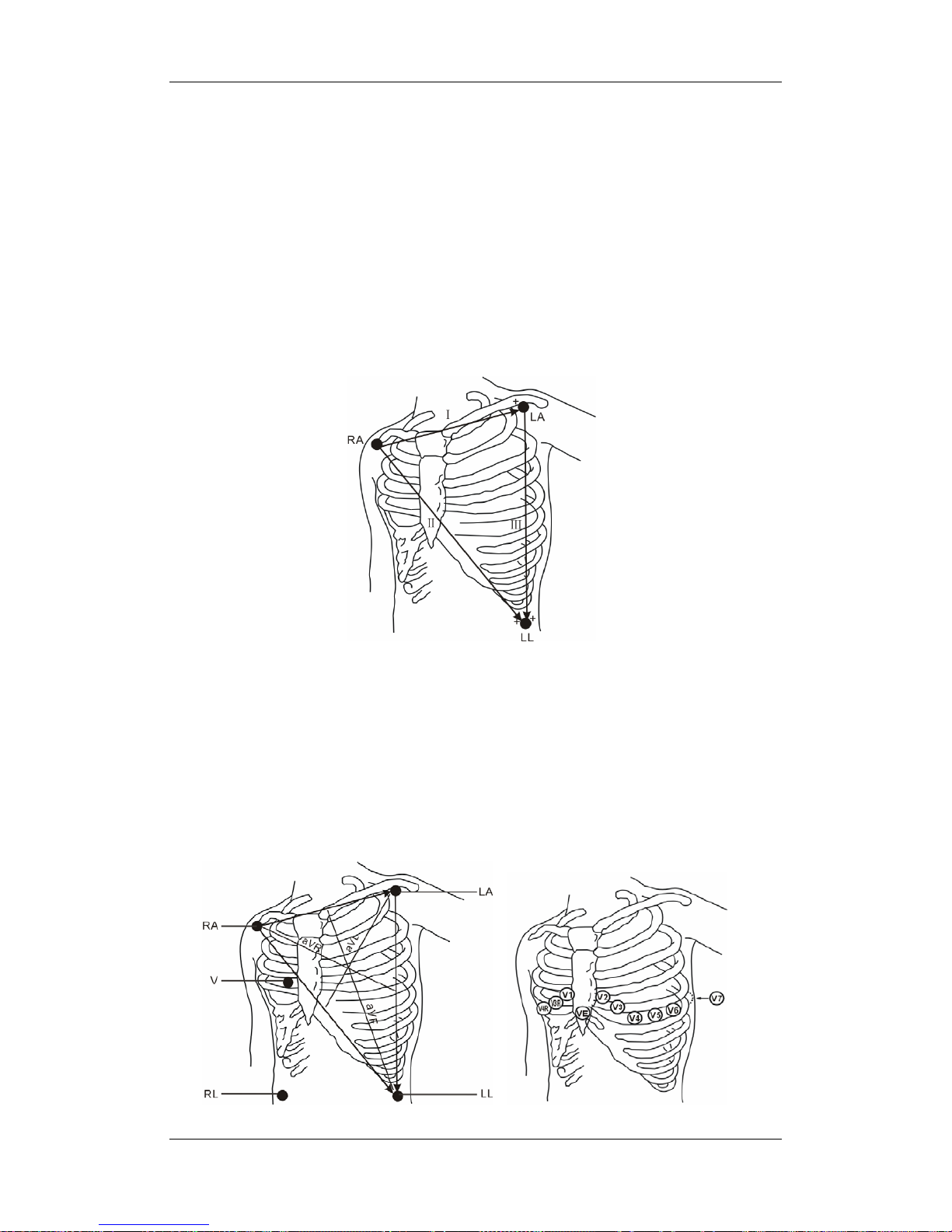
8-3
8.3.3 ECG Lead Placements
The electrode placement illustrations in this chapter adopt the AHA standard.
3-Leadwire Electrode Placement
Following is an electrode configuration when using 3 leadwires:
RA placement: directly below the clavicle and near the right shoulder.
LA placement: directly below the clavicle and near the left shoulder.
LL placement: on the left lower abdomen.
5-Leadwire Electrode Placement
Following is an electrode configuration when using 5 leadwires:
RA placement: directly below the clavicle and near the right shoulder.
LA placement: directly below the clavicle and near the left shoulder.
RL placement: on the right lower abdomen.
LL placement: on the left lower abdomen.
V placement: on the chest.
Page 82

8-4
The chest (V) electrode can be placed on one of the following positions:
V1 placement: on the fourth intercostal space at the right sternal border.
V2 placement: on the fourth intercostal space at the left sternal border.
V3 placement: midway between the V2 and V4 electrode positions.
V4 placement: on the fifth intercostal space at the left midclavicular line.
V5 placement: on the left anterior axillary line, horizontal with the V4 electrode
position.
V6 placement: on the left midaxillary line, horizontal with the V4 electrode position.
V3R-V6R placement: on the right side of the chest in positions corresponding to those
on the left.
VE placement: over the xiphoid process.
V7 placement: on posterior chest at the left posterior axillary line in the fifth intercostal
space.
V7R placement: on posterior chest at the right posterior axillary line in the fifth
intercostal space.
12-Leadwire Electrode Placement
12-lead ECG uses 10 electrodes, which are
placed on the patient’s four limbs and chest.
The limb electrodes should be placed on the
soft skin and the chest electrodes placed
according to the physician’s preference.
Lead Placement for Surgical
Patients
The surgical site should be taken into
consideration when placing electrodes on a
surgical patient. e.g. for open-chest surgery,
the chest electrodes can be placed on the
lateral chest or back. To reduce artifacts and
interference from electrosurgical units, you
can place the limb electrodes close to the
shoulders and lower abdomen and the chest
electrodes on the left side of the mid-chest.
Do not place the electrodes on the upper arm.
Otherwise, the ECG waveform will be very
small.
Page 83

8-5
WARNING
z When using electrosurgical units (ESU), patient leads should be placed in a
position that is equal distance from the Electrosurgery electrotome and the
grounding plate to avoid burns to the patient. Never entangle the ESU cable and
the ECG cable together.
z When using electrosurgical units (ESU), never place ECG electrodes near to the
grounding plate of the ESU, as this can cause a lot of interference on the ECG
signal.
8.3.4 Switching ECG Lead Set
When [Lead Set] is set to [Auto], the patient monitor can switch from 3-lead ECG to 5-lead
ECG, or from 5-lead ECG to 12-lead ECG automatically. The following table describes the
contions of the lead switch.
Switch from 3-lead to 5-lead RL and any two of limb leads (RA, LL, LA)
are connected to a patient for 5 seconds.
Switch from 5-lead to 3-lead RA, LA, LL, and V are all disconnected or
RL is disconnected from a patient and the
disconnection lasts for 10 seconds.
Switch from 12-lead to 3-lead All the leads are disconnected or RL is
disconnected from a patient and the
disconnection lasts for 10 seconds.
Switch from 5-lead to12-lead RA, LA, RL, and LL are connected to a
patient properly, any lead from V2 to V6 is
connected properly and the connection lasts
for 5 seconds.
Page 84

8-6
8.3.5 Checking Paced Status
It is important to set the paced status correctly when you start monitoring ECG. The paced
symbol
is displayed when the [Paced] status is set to [Yes]. The pace pulse markers “
|
”
are shown on the ECG wave when the patient has a paced signal.
To change the paced status, you can select either:
the patient information area, or
[Patient Setup >>] in the main menu and then [Patient Demographics], or,
the ECG parameter window,
and then, select [Paced] from the popup menu and toggle between [Yes] and [No].
WARNING
z For paced patients, you must set [Paced] to [Yes]. If it is incorrectly set to [No], the
patient monitor could mistake a pace pulse for a QRS and fail to alarm when the
ECG signal is too weak. Do not rely entirely on rate meter alarms when monitoring
patients with pacemakers. Always keep these patients under close surveillance.
z For non-paced patients, you must set [Paced] to [No]. If it is incorrectly set to [Yes],
the patient monitor may be unable to detect premature ventricular beats (including
PVCs) and perform ST segment analysis.
Page 85

8-7
8.4 Understanding the ECG Display
In the all parameters screen, the patient monitor allows up to three ECG to be displayed
simultaneously. Following is an ECG display screen with 5-lead set and for reference only.
Your display may be configured to look slightly different.
1. Lead label of the displayed wave 2. ECG gain
3. ECG filter label 4. Notch filter status
Besides, pace pulse marks “
|
” are shown above the ECG wave if the [Paced] is set to [Yes]
and the patient has a paced signal.
1. Current heart rate alarm limits
2. Heart beat symbol
3. Current heart rate
For 12-lead ECG display screen, refer to the section 12-Lead ECG Monitoring.
1 23 4
1
3
2
Page 86

8-8
8.5 Changing ECG Settings
8.5.1 Setting Pacemaker Rate (For Mortara Only)
Some pacemaker pulses cannot be rejected. When this happens, the pulses are counted as a
QRS complex and could result in an incorrect HR and a failure in detecting some
arrhythmias. Select [ECG Setup]→[Others >>], and you can set [Pacemaker Rate] to the
pacemaker’s rate in the popup menu. In this way, the patient monitor can calculate HR and
detect arrhythmias more accurately. When [Paced] is set to [No], the pacemaker rate cannot
be set.
8.5.2 Choosing the Alarm Source
In most cases the HR and PR numerics are identical. In order to avoid simultaneous alarms
on HR and PR, the monitor uses either HR or PR as its active alarm source. To change the
alarm source, select [Alm Source] in the [ECG Setup] menu and then select either:
[HR]: if you want the HR to be the alarm source for HR/PR.
[PR]: if you want the PR to be the alarm source for HR/PR.
[Auto]: If the [Alm Source] is set to [Auto], the monitor will use the heart rate from
the ECG measurement as the alarm source whenever the ECG measurement is
switched on and a valid heart rate is available. If the heart rate becomes unavailable,
for example if leads becomes disconnected, and a pulse source is switch on and
available, the monitor will automatically switch to Pulse as the alarm source. When the
Leads Off condition is corrected, the monitor will automatically switch back to the
heart rate as the alarm source.
8.5.3 Choosing a 5-Lead ECG Display Screen
When monitoring with a 5-lead set, you can, in the [ECG Setup] menu, set the [ECG
Display] screen to:
[Normal]: The ECG waveform area shows 2 ECG waveforms by default. You can
select 3 ECG waveforms for display.
[Full-Screen]: The whole waveform area shows 7 ECG waveforms only.
[Half-Screen]: The upper half part of the whole waveform area displays 7 ECG
waveforms.
Page 87

8-9
When [ECG Display] is set to [Normal] and [Sweep Mode] is set to [Refresh], cascaded
ECG waveforms can be displayed. To cascade ECG waveforms:
1. Select either ECG wave to enter its lead menu.
2. Select [Cascade] and then select [On]. A cascaded waveform is displayed in two
waveform positions.
8.5.4 Changing the ECG Filter Settings
The ECG filter setting defines how ECG waves are smoothed. The default filter mode is
different for different departments. To change the filter mode which will be applied for all
ECG waveforms, select either ECG wave to enter its lead menu and then set [Filter] to:
[Monitor]: Use under normal measurement conditions.
[Diagnostic]: Use when diagnostic quality is required. The unfiltered ECG wave is
displayed so that changes such as R-wave notching or discrete elevation or depression
of the ST segment are visible.
[Surgery]: Use when the signal is distorted by high frequency or low frequency
interference. High frequency interference usually results in large amplitude spikes
making the ECG signal look irregular. Low frequency interference usually leads to
wandering or rough baseline. In the operating room, the surgery filter reduces artifacts
and interference from electrosurgical units. Under normal measurement conditions,
selecting [Surgery] may suppress the QRS complexes too much and then interfere
with ECG analysis.
NOTE
z As the [Monitor] or [Surgery] filter may cause ECG waveform distortions, try to
use the [Diagnostic] filter for ST analysis as possible as you can. Besides, the
[Surgery] filter may also affect arrhythmia analysis results.
8.5.5 Switching the Notch Filter On or Off
The notch filter removes the line frequency interference. When [Filter] is not set to
[Diagnostic], the notch filter always stays on. When [Filter] is set to [Diagnostic], you can
switch the notch filter on or off as required.
1. Select the ECG parameter window to enter its setup menu and then select [Others >>].
2. Select [Notch Filter] and toggle between [On] and [Off]. Switching the notch filter on
is recommended when there is interference (such as spikes) with the waveform.
Page 88

8-10
Besides, you can set the notch frequency in maintenance mode:
1. In the main menu, Select [Maintenance >>]→[User Maintenance >>]→enter the
required password.
2. Select [Device Setup >>] and then set [Notch Filter] to [50Hz] or [60Hz] according
to the power line frequency.
8.5.6 Switching Defibrillator Synchronization On/Off
As defibrillator synchronization, analog output and nurse call share the same signal output
port, you need to set the port for defibrillator synchronization before getting the monitor and
defibrillator synchronized. To set the port for defibrillator synchronization:
1. In the main menu, Select [Maintenance >>]→[User Maintenance >>]→enter the
required password.
2. Select [Device Setup >>] to access the [Device Setup] menu.
3. Select [Auxiliary Output] and then [Defib. Sync].
To switch defibrillator synchronization on or off:
1. Select the ECG parameter window and then select [Others >>].
2. Select [Defib. Sync] and toggle between [On] and [Off].
If a defibrillator is connected, a defibrillator synchronization pulse (100 ms, +5V) is
outputted through the Defib. Sync connector every time when the patient monitor detects an
R-wave. When [Defib. Sync] is set on, the message [Defib Sync On] is displayed in the
technical alarm area.
WARNING
z Improper use of a defibrillator may cause injury to the patient. The user should
determine whether to perform defibrillation or not according to the patient’s
condition.
z Before defibrillation, the user must ensure both defibrillator and monitor has
passed the system test and can be safely used jointly.
z Before defibrillation, make sure that [Defib. Sync] is set to [On] and the [Filter] is
set to [Diagnostic].
z After defibrillation is finished, set [Defib. Sync] to [Off] and select the filter mode
as required.
Page 89

8-11
8.5.7 Selecting ECG Waves for Display
In the all parameters screen, the patient monitor allows up to three ECG to be displayed
simultaneously.
When monitoring with a 5-lead set, you can select [Waveforms] in the ECG setup menu
and then select either one, or two, or three waves for display. When you select three ECG
waves for display, there must be one ECG wave that will be displayed permanently on the
screen. For 5-lead ECG monitoring, the permanently displayed ECG wave is lead V, and for
12-lead ECG monitoring, the permanently displayed one is lead V1.
8.5.8 Changing ECG Wave Settings
To change a wave’s settings, select the wave you want to change to enter its lead menu.
If the wave is too small or clipped, you can change its size by selecting an appropriate
[Gain] setting. If you select [Auto] from [Gain], the patient monitor will automatically
adjust the size of the ECG waves. In the all parameters screen, only the selected ECG
wave’s size is adjusted. In other screens, all ECG waves’ size is adjusted
simultaneously.
You can adjust a wave’s position by adjusting the
or button beside [Adjust
Wave] button.
You can restore a wave to its original position by selecting [Back to Default].
8.5.9 Choosing an ECG Lead for HR Computing and Arrh.
Monitoring
For the Basic algorithm, to compute HR and to analyze and detect arrhythmia more
accurately, you can choose a lead of best quality signals as the HR lead. To select a lead as
the HR lead, in the all parameters screen, select the wave corresponding to the HR
parameter to enter its lead menu. In the lead menu, select [HR Source] and then select the
lead you want.
The selected lead should have the following characteristics:
The QRS should be tall and narrow, with no notch
R-wave should be either completely above or below the baseline and it should not be
biphasic.
The height of pace pulses should not be above R-wave
T-wave should be smaller than 1/3 R-wave height.
The P-wave should much smaller than the T-wave.
Page 90

8-12
For the Mortara algorithm, the system will analyze ECG waveforms from multiple channels
simultaneously so as to compute HR and to analyze and detect arrhythmia.
8.5.10 Adjusting QRS Volume
When HR is selected as the alarm source, QRS sounds are produced based on the HR. To
adjust the QRS volume, select [Beat Vol] in the [ECG Setup] menu and select the
appropriate setting. When a valid SpO
2
measured value is available, the system adjusts the
pitch tone of QRS volume based on the SpO
2
value.
8.6 About ST Monitoring
ST segment analysis is intended for adult patients. The default setting is off.
ST segment analysis calculates ST segment elevations and depressions for a specified
lead.
Measurement unit of the ST segment: mm or mV.
A positive value indicates ST segment elevation; a negative value indicates ST
segment depression.
Measurement range of the ST segment: -2.0 mV to +2.0 mV.
WARNING
z The ST algorithm has been tested for accuracy of the ST segment data. The
significance of the ST segment changes needs to be determined by a clinician.
8.6.1 Switching ST On and Off
To switch ST monitoring on or off:
1. Select the ECG parameter window and then select [ST Analysis >>] from the popup
menu.
2. Select [ST Analysis] to toggle between [On] and [Off].
Reliable ST monitoring can hardly be ensured if:
You are unable to get a lead that is not noisy.
Arrhythmias such as atrial fib/flutter cause irregular baseline.
The patient is continuously and ventricularly paced.
The patient has left bundle branch block.
In these cases, you may consider switching ST monitoring off.
Page 91

8-13
8.6.2 Changing ST Filter Settings
When ST-segment analysis is performed, dedicated filters are used to ensure the diagnostic
quality. When ST-segment analysis is switched on, [Filter] switches to [Diagnostic]
automatically when it is not in the diagnostic mode.
8.6.3 Understanding the ST Display
This example shows ST numerics with 5-lead ECG. Your monitor screen may look slightly
different from the illustration.
By selecting the ST parameter window, you can enter the [ST Analysis] menu.
8.6.4 Changing the ST Unit
In the [ST Analysis] menu, you can select [ST Unit] menu to toggle between [mm] and
[mV]. You can also change the ST unit in configuration mode.
8.6.5 Changing the ST Alarm Limits
For 3-lead ECG monitoring, you can directly change the ST alarm limits in the [ST
Analysis] menu. For 5- or 12-lead ECG monitoring, you can select [Adjust ST Limits >>]
from [ST Analysis] and then set the ST alarm limits for each lead.
Page 92

8-14
8.6.6 Setting ST Alarm Delay Time
You can set ST alarm delay time by selecting [ST Alarm Delay] from [ST Analysis>>].
The following ST alarm delay time is optional: 30s (default), 45s, 1min, 1.5min, 2 min, and
3min.
8.6.7 Adjusting ST Measurement Points
As shown in the figure below, the ST measurement for each beat complex is the vertical
difference between two measurement points with the R-wave peak as the baseline for the
measurement.
The ISO and ST points need to be adjusted when you start monitoring or if the patient’s
heart rate or ECG morphology changes significantly. Exceptional QRS complexes are not
considered for ST-segment analysis.
WARNING
z Always make sure that the positions of ST measurement points are appropriate for
your patient.
Basic algorithm
To adjust ST measurement points:
1. In the [ST Analysis] menu, select [Adjust ST Points >>]. In the [Adjust ST Points]
window, two vertical lines represent the ISO and ST point positions respectively.
2. Select the
and arrow keys beside the [ISO] or [ST] to move the measurement
points.
ISO-point (isoelectric): provides baseline for the measurement.
ST: marks the end point of the ST segment analysis.
R-wave peak
P
T
Isoelectric point ST measurement point Difference=ST value
Page 93

8-15
Mortara algorithm
1. In the [ST Analysis] menu, select [Adjust ST Points >>]. In the [Adjust ST Points]
window, three vertical lines represent the ISO, J and ST points’ positions respectively.
2. Select [View Leads] and use the Knob to select an ECG lead with obvious J point and
R wave.
3. Select [ISO], [J] or [ST] and then use the Knob to adjust the position of each point.
The ISO-point (isoelectric) position is given relative to the R-wave peak. Position
the ISO-point in the middle of the flattest part of the baseline (between the P and
Q waves or in front of the P wave).
The J-point position is given relative to the R-wave peak and helps locating the
ST-point. Position the J-point at the end of the QRS complex and the beginning of
the ST segment.
The ST-point is positioned a fixed distance from the J-point. Move the J-point to
position the ST-point at the midpoint of the ST segment. Position the ST-point
relative to the J-point at either J+60 or J+80.
8.7 About Arrhythmia Monitoring
Arrhythmia analysis provides information about your patient’s condition, including heart
rate, PVC rate, rhythm and ectopics. The arrhythmia detection is intended for adult and
pediatric patients.
WARNING
z Arrhythmia analysis program is intended to detect ventricular arrhythmias. It is
not designed to detect atrial or supraventricular arrhythmias. It may incorrectly
identify the presence or absence of an arrhythmia. Therefore, a physician must
analyze the arrhythmia information with other clinical findings.
Page 94

8-16
8.7.1 Understanding the Arrhythmia Events
Basic algorithm
Arrhythmia message Description
Asystole No QRS complex for 4 consecutive seconds (in absence of ventricular
fibrillation or chaotic signals).
Vfib/Vtac A fibrillatory wave for 4 consecutive seconds. A dominant rhythm of
adjacent Vs and a HR > the V-Tach Heart Rate Limit.
PNP No pace pulse detected for 1.75 x average R-to-R intervals following a
QRS complex (for paced patients only).
PNC No QRS complex detected for 300 milliseconds following a pace pulse
(for paced patients only).
PVC One PVC detected in normal heartbeats.
Couplet Paired PVCs detected in normal heartbeats.
VT>2 More than 2 consecutive PVCs within the last minute.
Bigeminy A dominant rhythm of N, V, N, V, N, V.
Trigeminy A dominant rhythm of N, N, V,N, N, V, N, N, V.
R on T R on T detected in normal heartbeats.
Missed Beats No beat detected for 1.75 x average R-R interval for HR <120, or No
beat for 1 second with HR >120 (for non-paced patients only), or No
beat detected for more than the set pause threshold.
Brady The average heart rate is less than 60 bpm.
Tachy The average heart rate is greater than 100 bpm.
Page 95

8-17
Mortara algorithm
Arrhythmia message Description
Asystole No QRS complex for 4 consecutive seconds (in absence of ventricular
fibrillation or chaotic signals).
Vfib Ventricular fibrillation occurs and persists for 6 seconds.
Vtac Ventricular HR is greater or equal to the preset threshold and the
number of consecutive PVCs is greater than the preset threshold.
PNP No pace pulse detected for (60*1000/pace rate +90) milliseconds
following a QRS complex or a pacer pulse (for paced patients only).
PNC No QRS complex detected for 300 milliseconds following a pace pulse
(for paced patients only).
Multif. PVC More than 2 PVCs of different forms occur in the predefined search
window (3-31).
Couplet Paired PVCs detected in normal heartbeats.
VT>2 Ventricular HR is greater than or equal to the preset threshold and the
number of PVCs is greater than or equal to 3 but less than the preset
threshold.
Vent. Rhythm Ventricular HR is less than the preset threshold and the number of
PVCs is greater than or equal to 3.
Bigeminy A dominant rhythm of N, V, N, V, N, V.
Trigeminy A dominant rhythm of N, N, V,N, N, V, N, N, V.
R on T R on T is detected.
Irr. Rhythm Consistently irregular rhythm
Missed Beats No beat detected for 1.75x average R-R interval for HR <120, or No
beat for 1 second with HR >120 (for non-paced patients only), or No
beat detected for more than the set pause threshold.
Brady The HR is less than the set bradycardia low limit.
Tachy The HR is greater than the set tachycardia high limit.
Page 96

8-18
8.7.2 Switching Arrhythmia Analysis On and Off
To switch arrhythmia analysis on or off:
1. Select the ECG parameter window and then select [Arrh. Analysis >>] from the
popup menu.
2. Select [Arrh. Analysis] to toggle between [On] and [Off].
When arrhythmia analysis is turned off, the PVC numeric will not be displayed.
8.7.3 Changing Arrhythmia Alarm Settings
To change arrhythmia alarm settings, select the ECG parameter area and then select [Arrh.
Analysis >>]. In the [Arrh. Analysis] menu, you can:
switch on or off the alarm for PVCs by selecting [PVCs] and then toggling between
[On] and [Off].
set the alarm level, alarm record, and alarm limit for PVCs by selecting [Alm Lev],
[Alm Rec] and [PVCs High] respectively and then selecting the appropriate settings.
select [Arrh. Alarm Setup >>] to change alarm settings for individual arrhythmia
events. For Mortara algorithm, Asystole, Vfib and Vtac are exclusively high-level
alarms and their alarm level is unchangeable. Furthermore, these alarms will be
triggered only if their alarm conditions are active, regardless of whether arrhythmia
analysis is switched on.
8.7.4 Changing Arrhythmia Threshold Settings (For Mortara
Only)
Select the ECG parameter window→[Arrh. Analysis >>]→[Arrh. Threshold Setup], and
you can then change threshold settings for some arrhythmia alarms. In case an arrhythmia
violates its threshold, an alarm will be triggered. The asystole delay time relates to
arrhythmia relearning. When HR is less than 30 bpm, it is recommended to set the asystole
delay time to 10 seconds.
PVC numeric
Page 97

8-19
Mortara algorithm
Arrh. event Range Default configurations Interval Unit
Asys. Delay 2 to 10 NICU: 3
Other departments: 5
1 s
Vtac Rate 100 to 200 NICU: 150
Other departments: 130
5 bpm
Vtac PVC 3 to12 6 1 beats
Multif. PVC’s
Window
3 to 31 15 1 beats
Tachy High Adult: 100 to 300
Pediatric: 160 to 300
Neonate: 180 to 350
Adult: 100
Pediatric: 160
Neonate: 180
5 bpm
Brady Low Adult: 15 to 60
Pediatric: 15 to 80
Neonate: 15 to 90
Adult: 60
Pediatric: 80
Neonate: 90
5 bpm
8.7.5 Initiating Arrhythmia Relearning Manually
During ECG monitoring, you may need to initiate an arrhythmia relearning when the
patient’s ECG template changes dramatically. A change in the ECG template could result in:
incorrect arrhythmia alarms
loss of ST measurement, and/or
inaccurate heart rate
Arrhythmia relearning allows the monitor to learn the new ECG template so as to correct
arrhythmia alarms and HR value, and restore ST measurements. To initiate a relearning
manually, select the ECG parameter window→[Arrh. Analysis >>]→[Relearn Arrh.].
When the patient monitor is learning, the message [Arrh. Learning] is displayed in the
technical alarm area.
CAUTION
z Take care to initiate arrhythmia relearning only during periods of predominantly
normal rhythm and when the ECG signal is relatively noise-free. If arrhythmia
learning takes place during ventricular rhythm, the ectopics may be incorrectly
learned as the normal QRS complex. This may result in missed detection of
subsequent events of V-Tach and V-Fib.
Page 98

8-20
8.7.6 Automatic Arrhythmia Relearn
Arrhythmia relearning is initiated automatically whenever:
The ECG lead or lead label is changed
The HR computing lead is changed.
The ECG lead is re-connected
A new patient is admitted
The paced status setting is changed
Arrhythmia analysis is switched on.
The ECG module becomes active.
After the calibration is completed, select [Stop Calibrating ECG]
8.7.7 Reviewing Arrhythmia Events
To review previously happened arrhythmia events, in the [ECG Setup] menu, select [Arrh.
Analysis >>]→[Arrh. Review >>].
In the [Arrh. Review] window, you can:
Select [Index] and then set a time as the index for finding your desired arrhythmia
events.
Rename an arrhythmia event by selecting the arrhythmia event you want to rename and
then selecting [Rename] to enter a new name for it.
Delete an arrhythmia event by selecting the one you want to delete and then selecting
[Delete Event].
Have more event selections by selecting
, , or .
After an event is selected, select [Waveforms] and then select
or beside
[Scroll] to navigate through the waveforms.
Print out the currently displayed arrhythmia waveforms and numerics through the
recorder by selecting [Record].
Print out the currently displayed arrhythmia waveforms and numerics through the
printer by selecting [Print].
Page 99

8-21
8.8 12-Lead ECG Monitoring
8.8.1 Entering the 12-lead ECG Monitoring Screen
1. Refer to the section 8.3.3 ECG Lead Placement for placing the electrodes.
2. Select the ECG parameter window and then set [Lead Set] to [12-Lead], and [ECG
Display] to [12-Lead] in the popup menu.
There are totally 12 ECG waves and 1 rhythm wave displayed on the screen. The rhythm
lead is the HR-derived lead before entering the 12-lead ECG monitoring screen. The ST
numerics are displayed in three groups:
ST Ant (anterior): V1, V2, V3, V4
ST Inf (inferior): II, III, aVF, (aVR)
ST Lat (lateral): I, aVL, V5, V6
Although aVR is displayed in the ST Inf group, it is not an inferior lead.
Additionally, the 12-lead ECG monitoring has the following features:
The [Filter] mode is fixed to [Diagnostic] and cannot be changed.
The
hardkey on the monitor’s front is disabled.
Page 100

8-22
8.8.2 Interpretation of resting 12-Lead ECG
Interpretation of resting 12-lead ECG is intended for adult patients.
You can only start an interpretation of resting 12-lead ECG 11 seconds after entering the
12-lead ECG monitoring screen. Otherwise, the prompt message [Not enough data.
Cannot analyze.] will be displayed. To start an interpretation of resting 12-lead ECG, select
[Freeze] and then [Analyze]. Then, the following screen will be displayed. In this screen,
you can:
Select [Record Result] to print out the interpretation of resting 12-lead ECG results by
the recorder.
Select [Record Wave] to print out the interpretation of resting 12-lead ECG results
and waves by the recorder.
Select [Print Report] to print out the interpretation of resting 12-lead ECG report by
the printer.
Besides, after selecting [Freeze], you can:
Browse the frozen ECG waves by selecting [Scroll] and rotating the Knob, or selecting
the
or button beside [Scroll].
Print out the currently frozen waves by selecting [Record].
 Loading...