


OPERATOR'S MANUAL
MANUEL de L'UTILISATEUR
MANUAL del OPERADOR
Cat. No. No de cat. 2212-20 2213-20
AUTO VOLTAGE/CONTINUITY TESTER AND AUTO VOLTAGE/CONTINUITY TESTER W/ RESISTANCE
TESTEUR AUTOMATIQUE DE TENSION/CONTINUITÉ ET TESTEUR AUTOMATIQUE DE TENSION/CONTINUITÉ AVEC RÉSISTANCE
PROBADOR AUTOMÁTICO DE VOLTAJE/CONTINUIDAD Y PROBADOR AUTOMÁTICO DE VOLTAJE/CONTINUIDAD CON RESISTENCIA
TO REDUCE THE RISK OF INJURY, USER MUST READ AND UNDERSTAND OPERATOR'S MANUAL.
AFIN DE RÉDUIRE LE RISQUE DE BLESSURES, L'UTILISATEUR DOIT LIRE ET BIEN COMPRENDRE LE MANUEL DE L'UTILISATEUR.
PARA REDUCIR EL RIESGO DE LESIONES, EL USUARIO DEBE LEER Y ENTENDER EL MANUAL DEL OPERADOR.
IMPORTANT SAFETY INSTRUCTIONS
 WARNING READ ALL SAFETY WARNINGS AND INSTRUCTIONS. Failure to follow the warnings and instructions may result in electric shock, fire and/or serious injury, as well as instrument damage and/or damage to the equipment being tested. Save these instructions - This operator’s manual contains important safety and operating instructions for the MILWAUKEE Electrical Testers. Before using, read this operator’s manual and all labels on the Electrical Testers.
 DANGER
Never make measurement on a circuit in which voltage over 600V rms exists. Use only leads rated 600V CAT IV or better.
Do not apply more than the rated voltage, as marked on the Tester, between terminals or between any terminal and earth ground.
Do not attempt to make measurement in the presence of flammable gases. Otherwise, the use of the instrument may cause sparking, which can lead to an explosion.
Never attempt to use the instrument if its surface or your hand is wet. Do not exceed the maximum allowable input of any measuring range. Only test on unenergized circuits unless absolutely necessary.
Check tool functionality on a known circuit first. Never assume tool is working.Assume circuits are live until they can be proven de-energized.
Never open the Battery cover during a measurement.
Do not ground yourself while measuring. Avoid body contact with earthed or grounded surfaces such as pipes, radiators, ranges and refrigerators. Thisinstrumentistobeusedonlyinitsintendedapplicationsorconditions.Otherwise,theinstrument'ssafetyfunctionsmaynotwork,resultinginseriouspersonalinjuryandinstrumentdamage. To reduce the risk of injury from shock and arc blasts, always wear personal protective equipment where live conductors are exposed.
 WARNING
Never attempt to make measurement if any abnormal conditions, such as broken case and exposed metal parts are found on the instrument.
Comply with local and national safety requirements when working in hazardous locations. Keep fingers behind the guards and away from test lead tips during measurements.
Do not change the slide switch position (Cat. No. 2213-20) while the test leads are being connected.
Verify proper operation on a known source before use or taking action as a result of the indication of the instrument.
Do not install substitute parts or make any modification to the instrument. For repair, return the tool to a factory Service/Sales Support Branch or authorized service station.
Do not try to replace the batteries if the surface of the instrument is wet.
Disconnect all the cords and cables from the object under test and power off the instrument before opening the Battery Cover for Battery replacement.
This tool is designed to be powered by 2- AAA batteries properly inserted in the Milwaukee Electrical Tester. Do not use with any other voltage or power supply.
Install battery according to polarity (+ and –) diagrams. Do not leave batteries within the reach of children.
Do not mix new and used batteries. Do not mix brands (or types within brands) of batteries. Properly dispose of used batteries.
Do not incinerate or dismantle batteries.
Under abusive conditions, liquid may be ejected from the battery, avoid contact. If contact accidentally occurs, flush with water. If liquid contacts eyes, additionally seek medical help. Liquid ejected from the battery may cause irritation or burns.
 CAUTION
Set the Slide Switch (Cat. No. 2213-20) to an appropriate position before starting measurement.
Disconnect test leads from test points before changing the slide switch function (Cat. No. 2213-20).
Never connect to a source of voltage with the tester OFF or slide switch position in Ω (Cat. No. 2213-20).
Firmly insert the test leads.
Do not expose the instrument to the direct sun, high temperature and humidity or dew fall. Altitude 2000m or less. Appropriate operating temperature is within 0ºC and 50ºC.
Keep away from excess dust and water.
Be sure to power off the instrument after use. When the instrument will not be in use for a long period, place it in storage after removing the batteries.
Use a damp cloth or neutral detergent for cleaning the instrument. Do not use abrasives or solvents.
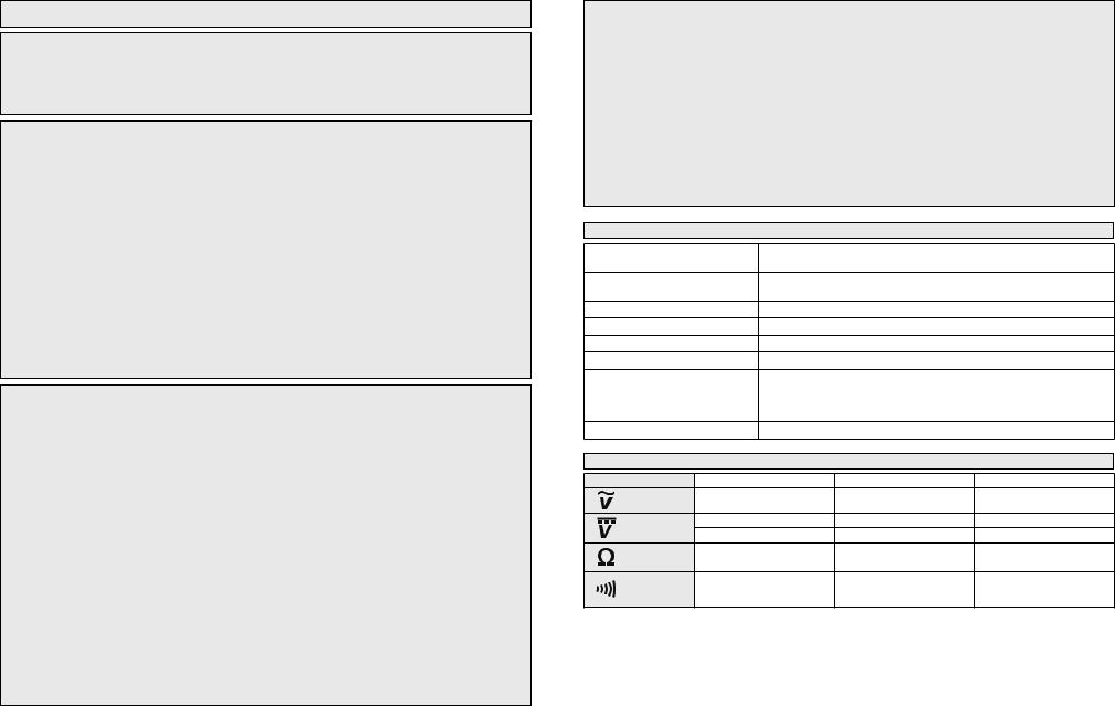
GENERAL SPECIFICATIONS
Maximum voltage between |
600V CAT IV |
any terminal and earth ground |
|
Temperature |
Operating: 0°C to 50°C (32°F to 122°F) |
|
||
|
Storage: -10°C to 60 °C (-14°F to 140°F) |
|
||
Operating Altitude |
2,000 m |
|
|
|
Drop Test |
1 m |
|
|
|
Battery |
2 AAA, NEDA 24 A,IEC LR03 |
|
||
Battery Life |
Approx. 20 Hours normal use |
|
||
Safety Compliances |
UL/CSA/IEC/EN 61010-1 3rd Edition and IEC/EN 61010-2-033 1st |
|||
|
Edition (Meter), UL/CSA/IEC/EN 61010-031 1st Ed + A1 (Probes). |
|||
|
Measurement Category IV, 600V, Pollution Degree II, |
|||
|
EMC EN 61326-1. |
|
|
|
Certifications |
cULus, CE |
|
|
|
|
FUNCTIONS |
|
||
Function |
Range |
Resolution |
Accuracy† |
|
Voltage AC |
5 - 600 V |
1 V |
±(3.0% + 5 dgt) |
|
Voltage DC |
2 - 199.9 V |
0.1 V |
±(3.0% + 5 dgt) |
|
200 - 600 V |
1 V |
±(3.0% + 5 dgt) |
||
|
||||
Resistance |
2 - 20 kΩ |
0.01 kΩ |
±(3.0% + 5 dgt) |
|
Continuity |
Continuity Buzzer |
|
Continuity Buzzer sounds |
|
0 - 20 kΩ |
|
at 20 kΩ or less |
||
|
|
|||
† Accuracy specified as ±(% of reading + 5 digits)
*Input impedance AC/DC Voltage : 300 kΩ
*Overload protection:
For 2212-20 - Meter protected for inputs above rated voltage AC/DC 600 V
For 2213-20 - Function Switch at 


 , Meter protected for inputs above rated voltage AC/DC 600 V Function Switch at Ω , Meter protected for inputs above rated voltage AC/DC 420 V
*Test leads rated for 10A with: measurement time 30 seconds maximum, rest time 20 minutes minimum, 40°C ambient.
2 |
3 |

SYMBOLOGY
Read Operator’s Manual
Double insulation
Earth
Danger, Warning, or Caution - Consult the operators manual for additional safety information.
Risk of electrical shock - To avoid electric shock, remove test leads before opening battery door
Battery compartment
European Conformity Mark
Underwriters Laboratories, Inc.,
United States and Canada
Classification of transient Cat IV overvoltages, based on
nominal line voltage to earth.
Do not dispose of this product as unsorted municipal waste.
FUNCTIONAL DESCRIPTION
1. |
Display |
9 |
8 |
7 |
2. |
Worklight button |
|
||
|
|
|
||
3. |
Power button |
|
|
|
4. |
Function switch |
|
|
|
|
(Cat.No. 2213 only) |
1 |
|
|
5. |
COM Terminal input |
|
|
|
2 |
|
|
||
6. |
Ω Terminal input |
|
|
|
7. |
Indicator |
|
|
|
8. |
LED Worklight |
3 |
|
|
9. |
Indicator |
|
|
|
10. Probe storage |
|
|
|
|
11. Grips |
4 |
|
|
|
12. Accessory bay |
|
|
||
|
|
|
||
12 |
5 |
|
6 |
|
|
|
|
||
|
11 |
|
|
|
|
10 |
|
|
|
ASSEMBLY
 WARNING To avoid an electrical hazard, turn the tester OFF and disconnect the test leads before replacing batteries.
Loading/Changing the Batteries
Replace batteries when the Low Battery indicator is displayed.
1.Press the Power ON/OFF button to turn off the tester. Disconnect the test leads.
2. Unscrew and remove battery door.
3. Insert two (2) AAA batteries, according to the polarity marked in the battery compartment
4. Close the battery door and tighten two (2) screws securely.
Installing/Removing the Belt Clip
The belt clip can be removed/installed into the accessory bay. Line up the belt clip and secure with the accessory bay screw.
Storage
To store the leadwires when not in 


 use, rotate the belt clip 90°. Wrap
 the leadwires around the body of the


 tester. Rotate the belt clip down to


 hold the leadwires in place.


Probe Tip Sleeves
Measurement Category and Voltage Rating of the Test Leads:
Probe Tip Sleeves ON: Cat IV, 600V / CAT III 1000V
Probe Tip Sleeves OFF: Cat II 1000V To remove the probe tip sleeves:
1.Disconnect the test leads from the tester.
2.Grasp the probe firmly in one hand.
3.Hold the probe tip sleeve firmly with the other hand.
4.Pull to remove the probe tip sleeve to expose more of the probe tip.
5.Push probe tip sleeve back onto probe tip when not in use.
OPERATION
 WARNING Only use Milwaukee test leads with the MILWAUKEE Tester. Inspect test leads for continuity before each use. Do not use if the readings are high or noisy.
 LCD Backlight
The LCD backlight will turn off about 20 seconds after Power-ON is pressed. The backlight will be triggered on every time a voltage is measured higher than 5 V AC/DC. It will not reactivate under resistance or continuity measurements.
LED Worklight
Press the Worklight Button to turn the LED on and off. The worklight will turn off automatically after about 1 minute. It is not necessary to turn on the Tester to use the worklight.
Making a Measurement
Auto-Function
The tester is designed to auto range at all times. With Auto Ranging, the tool will automatically select the range with the best resolution
The Tester automatically switches from Voltage AC/ DC measurement to Continuity when no voltage is present. The tool will automatically identify VAC from VDC and will indicate which on the display.
Hazard Voltage Warning
If measured voltage is over AC/DC 35 V, the 
Indicator LED will be lit RED and the buzzer will sound with steady, intermittent beeps (B_B_B).
Over-Range Indication
If measured voltage exceeds the measuring range
(over approximately 600V), the  and
and 

 Indicator LEDs flash rapidly, alternating RED and YELLOW. The buzzer will sound with bursts of three repeating beeps (BBB_BBB_BBB).
Auto Off Function
The tester is automatically powered off in about 10 minutes after Power-ON is pressed, preceded by two beeps. To continue use, press the PowerON again after shut-off. If the display is still blank, replace the batteries.
4 |
5 |
 DANGER To avoid electrical shock: Never make measurement on a circuit in which voltage over 600V AC/DC exists.
Do not use with the Battery Cover removed. Keep fingers behind the guards and away from test lead tips during measurements.
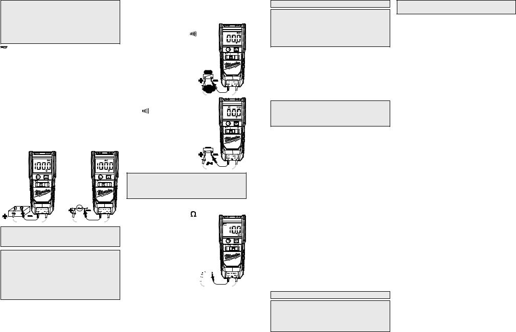
 AC/DC Voltage
The Electrical Tester automatically identifies AC or DC sources and indicates the type of voltage on the LCD screen using AC or DC .
1.Set the Slide Switch to  position (Cat. No. 2213-20 only).
2.Connect the red test lead to the VΩterminal and the black test lead to the COM terminal.
3.Connect the test leads to the circuit under test.
4.If voltage is present, the measurement will be displayed on the screen. If measured voltage
is over AC/DC 35 V, the  Indicator LED will be lit RED and the buzzer will sound with steady, intermittent beeps (B_B_B).
NOTE: When DC voltage is displayed, a reversed connection (red test lead to the negative (-) side
and black test leads to the positive (+) side of the circuit) is indicatedġ as a negative value.
CAUTION Readings may fluctuate or be influenced in noisy environment.
DANGER To reduce the risk of electric shock for Continuity or Resistance measurements, never use the Tester on an energized circuit. Make sure a capacitor is fully discharged before touching or attempting to make a measurement.
Do not use with the Battery Cover removed.


 Continuity
If voltage is not present, the tester will automati-
cally switch to continuity test mode and provide |
|
test results indicating whether |
|
continuity is present or not. |
|
1. Set the Slide Switch to |
|
position (Cat. No. 2213-20 |
|
only). |
|
2. Connect the red test lead |
|
to the VΩ terminal and the |
|
black test lead to the COM |
|
terminal. |
|
Short-circuit the tips of test |
|
leads to make the indication |
|
zero. A buzzer will sound. |
|
3. Connect the test leads to |
|
both end of the conductor |
|
under test. If the resistance |
|
under test is 20 kΩ or less, |
|
the |
Indicator LED will |
be lit YELLOW and buzzer |
|
will sound with a continuous |
|
beep. |
|
 CAUTION After shorting the test leads, the displayed value may not be zero due to the resistance of test leads themselves.
 Resistance (Cat. No. 2213-20 only)
1. Set the Slide Switch to position.
2. Connect the red test lead to the VΩ terminal and the black test lead to the COM terminal. Confirm “OL” is indicated on the display, and then short-circuit the tips of test leads to make the indication zero.
3. Connect the test leads to 


 the both ends of the resistor


 under test.
4. The reading is displayed.
6
MAINTENANCE
 WARNING To reduce the risk of injury, always remove the batteries from the tool before performing any maintenance. Never disassemble the tool. Contact a MILWAUKEE service facility for ALL repairs.
Maintaining Tool
Keep your tool in good repair by adopting a regular maintenance program. After six months to one year, depending on use, return the tool to a MILWAUKEE service facility for repairs.
If the tool does not start or operate at full power with new batteries, clean the contacts on the battery door. If the tool still does not work properly, return the tool to a MILWAUKEE service facility for repairs.
 WARNING To reduce the risk of personal injury and damage, never immerse your tool in liquid or allow a liquid to flow inside it.
Cleaning
Clean dust and debris from tool. Keep tool clean, dry and free of oil or grease. Use only mild soap and a damp cloth to clean the tool since certain cleaning agents and solvents are harmful to plastics and other insulated parts. Some of these include gasoline, turpentine, lacquer thinner, paint thinner, chlorinated cleaning solvents, ammonia and household detergents containing ammonia. Never use flammable or combustible solvents around tools.
Repairs
For repairs, return the tool to the nearest service center listed on the back cover of this operator's manual.
ACCESSORIES
 WARNING Always remove batteries before changing or removing accessories. Only use accessories specifically recommended for this tool. Others may be hazardous.
For a complete listing of accessories refer to your
MILWAUKEE Electric Tool catalog or go online to www.milwaukeetool.com. To obtain a catalog, contact your local distributor or service center.
FIVE YEAR TOOL LIMITED
WARRANTY
MILWAUKEE Test & Measurement Product (including bare tool, M12™ battery pack(s) and battery charger) is warranted to the original purchaser only to be free from defects in material and workmanship. Subject to certain exceptions, MILWAUKEE will repair or replace any part on this product which, after examination, is determined by MILWAUKEE to be defective in material or workmanship for a period of five (5) years* after the date of purchase. Return of the Test & Measurement tool to the nearest Milwaukee Electric Tool Corporation - factory Service Center, freight prepaid and insured is required. A copy of the proof of purchase should be included with the return product. This warranty does not apply to damage that MILWAUKEE determines to be from repairs made or attempted by anyone other than MILWAUKEE authorized personnel, misuse, alterations, abuse, normal wear and tear, lack of maintenance, or accidents.
* See separate & distinct CORDLESS BATTERY PACK LIMITED WARRANTY statement for the warranty period of the LITHIUM-ION battery pack that ships with Test & Measurement Product. *Alkaline battery that ships with Test & Measurement Product is separately warranted by the alkaline battery manufacturer.
*The warranty period for a Voltage Detector with Work Light – 2201 20, Voltage Detector with LED – 2202-20 or M12™ 2-Beam Plumb Laser – 2230 20 is one (1) year from the date of purchase.
Warranty Registration is not necessary to obtain the applicable warranty on MILWAUKEE product. The manufacturing date of the product will be used to determine the warranty period if no proof of purchase is provided at the time warranty service is requested.
ACCEPTANCE OF THE EXCLUSIVE REPAIR AND REPLACEMENT REMEDIES DESCRIBED HEREIN IS A CONDITION OF THE CONTRACT FOR THE PURCHASE OF EVERY MILWAUKEE PRODUCT. IF YOU DO NOT AGREE TO THIS CONDITION, YOU SHOULD NOT PURCHASE THE PRODUCT. IN NO EVENT SHALL MILWAUKEE BE LIABLE FOR ANY INCIDENTAL, SPECIAL, CONSEQUENTIAL OR PUNITIVE DAMAGES, OR FOR ANY COSTS, ATTORNEY FEES, EXPENSES, LOSSES OR DELAYS ALLEGED TO BE AS A CONSEQUENCE OF ANY DAMAGE TO, FAILURE OF, OR DEFECT IN ANY PRODUCT INCLUDING, BUT NOT LIMITED TO, ANY CLAIMS FOR LOSS OF PROFITS. SOME STATES DO NOT ALLOW THE EXCLUSION OR LIMITATION OF INCIDENTAL OR CONSEQUENTIAL DAMAGES, SO THE ABOVE LIMITATION OR EXCLUSION MAY NOT APPLY TO YOU. THIS WARRANTY IS EXCLUSIVE AND IN LIEU OF ALL OTHER WARRANTIES, WRITTEN OR ORAL. TO THE EXTENT PERMITTED BY LAW, MILWAUKEE DISCLAIMSANY IMPLIED WARRANTIES, INCLUDING WITHOUT LIMITATION ANY IMPLIED WARRANTY OF MERCHANTABILITY OR FITNESS FOR A PARTICULAR USE OR PURPOSE; TO THE EXTENT SUCH DISCLAIMER IS NOT PERMITTED BY LAW, SUCH IMPLIED WARRANTIES ARE LIMITED TO THE DURATION OF THE APPLICABLE EXPRESS WARRANTY AS DESCRIBED ABOVE. SOME STATES DO NOT ALLOW LIMITATIONS ON HOW LONG AN IMPLIED WARRANTY LASTS, SO THE ABOVE LIMITATION MAY NOT APPLY TO YOU, THIS WARRANTY GIVES YOU SPECIFIC LEGAL RIGHTS, AND YOU MAYALSO HAVE OTHER RIGHTS WHICH VARY FROM STATE TO STATE.
This warranty applies to product sold in the U.S.A. and 7 Canada only.
 Loading...