


OPERATOR'S MANUAL
MANUEL de L'UTILISATEUR
MANUAL del OPERADOR
Catalog No. No de Cat.
Número de Catálogo
6176-20
HEAVY-DUTY 14" ABRASIVE CUT-OFF MACHINE
EXTRA ROBUSTE TRONÇONNEUSE 35,6 cm À DISQUE ABRASIF SIERRA TRONZADORA ABRASIVA DE 35,6 cm, HEAVY DUTY
TO REDUCE THE RISK OF INJURY, USER MUST READ AND UNDERSTAND OPERATOR'S MANUAL.
AFIN DE RÉDUIRE LE RISQUE DE BLESSURES, L'UTILISATEUR DOIT LIRE ET BIEN COMPRENDRE LE MANUEL DE L'UTILISATEUR.
PARA REDUCIR EL RIESGO DE LESIONES, EL USUARIO DEBE LEER Y ENTENDER EL MANUAL DEL OPERADOR.

GENERAL SAFETY RULES
WARNING!
READ AND UNDERSTAND ALL INSTRUCTIONS
Failure to follow all instructions listed below, may result in electric shock, fire and/or serious personal injury.
SAVE THESE INSTRUCTIONS
WORK AREA
1.Keep work area clean and well lit. Cluttered, dark work areas invite accidents.
2.Avoid dangerous environments. Do not use your power tool in rain, damp or wet locations or in the presence of explosive atmospheres (gaseous fumes, dust or flammable materials). Remove materials or debris that may be ignited by sparks.
3.Keep bystanders away. Children and bystanders should be kept at a safe distance from the work area to avoid distracting the operator and contacting the tool or extension cord.
4.Protect others in the work area from debris such as chips and sparks. Provide barriers or shields as needed.
5.Make workshop child proof with padlocks, master switches, or by removing starter keys.
ELECTRICAL SAFETY
6.Grounded tools must be plugged into an outlet properly installed and grounded in accordance with all codes and ordinances. Never remove the grounding prong or modify the plug in any way. Do not use any adaptor plugs. Check with a qualified electrician if you are in doubt as to whether the outlet is properly grounded. If the tool should electrically malfunction or break down, grounding provides a low resistance path to carry electricity away from the user.
7.Double insulated tools are equipped with a polarized plug (one blade is wider than the other). This plug will fit in a polarized outlet only one way. If the plug does not fit fully in the outlet, reverse the plug. If it still does not fit, contact a
qualified electrician to install a polarized outlet. Do not change the plug in any way. Double insulation eliminates the need for the three wire grounded power cord and grounded power supply system.
8.Guard against electric shock. Prevent body contact with grounded surfaces such as pipes, radiators, ranges and refrigerators. When making blind or plunge cuts, always check the work area for hidden wires or pipes. Hold your tool by insulated nonmetal grasping surfaces. Use a Ground Fault Circuit Interrupter (GFCI) to reduce shock hazards.
9.Do not expose to rain or use in damp locations.
10.Do not abuse the cord. Never use the cord to carry the tools or pull the plug from an outlet. Keep cord away form heat, oil, sharp edges or moving parts. Replace damaged cords immediately. Damaged cords increase the risk of electric shock.
PERSONAL SAFETY
11.Know your power tool. Read this manual carefully to learn your power tool’s applications and limitations as well as potential hazards associated with this type of tool.
12.Stay alert, watch what you are doing, and use common sense when operating a power tool. Do not use tool while tired or under the influence of drugs, alcohol, or medication. A moment of inattention while operating power tools may result in serious personal injury.
13.Dress properly. Do not wear loose clothing or jewelry. Wear a protective hair covering to contain long hair. These may be caught in moving parts. When working outdoors, wear rubber gloves and insulated non-skid footwear. Keep hands and gloves away from moving parts.
14.Reduce the risk of unintentional starting. Be sure your tool is turned off before plugging it in. Do not use a tool if the power switch does not turn the tool on and off. Do not carry a plugged-in tool with your finger on the switch.
15.Remove all adjusting keys and wrenches. Make a habit of checking that adjusting keys, wrenches, etc. are removed from the tool before turning it on.
16.Do not overreach. Maintain control. Keep proper footing and balance at all times. Maintain a firm grip. Use extra care when using tool on ladders, roofs, scaffolds, etc.
17.Use safety equipment. Everyone in the work area should wear safety goggles or glasses with side shields complying with current safety standards. Everyday eyeglasses only have impact resistant lenses. They are not safety glasses. Wear hearing protection during extended use and a dust mask for dusty operations. Hard hats, face shields, safety shoes, etc. should be used when specified or necessary. Keep a fire extinguisher nearby.
18.Keep guards in place and in working order.
19.Never stand on tool. Serious injury could occur if the tool is tipped or if the cutting tool is unintentionally contacted.
20.Keep hands away from all cutting edges and moving parts.
TOOL USE AND CARE
21.Secure work. Use a clamp, vise or other practical means to hold your work securely, freeing both hands to control the tool.
22.Do not force tool. Your tool will perform best at the rate for which it was designed. Excessive force only causes operator fatigue, increased wear and reduced control.
23.Use the right tool. Do not use a tool or attachment to do a job for which it is not recommended. For example, do not use a circular saw to cut tree limbs or logs. Do not alter a tool.
24.Unplug tool when it is not in use, before changing accessories or performing recommended maintenance.
25.Store idle tools. When not in use, store your tool in a dry, secured place. Keep out of reach of children.
26.Never leave the tool running unattended. Turn power off. Do not leave the tool until it comes to a complete stop.
27.Check for damaged parts. Inspect guards and other parts before use. Check for misalignment, binding of moving parts, improper mounting, broken parts and any other conditions that may affect operation. If abnormal noise or vibration occurs, turn the tool off immediately and have the problem corrected before further use. Do not use a damaged tool. Tag damaged tools “DO NOT USE” until repaired. A guard or other damaged part should be properly repaired or replaced by a MILWAUKEE service facility. For all repairs, insist on only identical replacement parts.
page 2
28.Use proper accessories. Consult this manual for recommended accessories. Using improper accessories may be hazardous. Be sure accessories are properly installed and maintained. Do not defeat a guard or other safety device when installing an accessory or attachment.
29.Maintain tools carefully. Keep handles dry, clean and free from oil and grease. Keep cutting edges sharp and clean. Follow instructions for lubricating and changing accessories. Periodically inspect tool cords and extension cords for damage. Have damaged parts repaired or replaced by a MILWAUKEE service facility.
30.Maintain labels & nameplates. These carry important information. If unreadable or missing, contact a MILWAUKEE service facility for a free replacement.
SERVICE
31.Tool service must be performed only by qualified repair personnel. Service or maintenance performed by unqualified personnel may result in a risk of injury.
32.When servicing a tool, use only identical replacement parts. follow instructions in the maintenance section of this manual. Use of unauthorized parts or failure to follow maintenance instructions may create a risk of shock or injury.
SPECIAL SAFETY INSTRUCTIONS - ABRASIVE CUT-OFF MACHINES
WARNING!
To reduce the risk of injury, avoid inhalation of dust generated by grinding and cutting operations. Exposure to dust may cause respiratory ailments. Use approved NIOSH or OSHA respirators, safety glasses or face shields, gloves and protective clothing. Provide adequate ventilation to eliminate dust, or to maintain dust level below the Threshold Limit Value for nuisance dust as classified by OSHA.
WARNING! Some dust created by power sanding, sawing, grinding, drilling, and other construction activities contains chemicals known to cause cancer, birth defects or other reproductive harm. Some examples of these chemicals are:
•lead from lead-based paint
•crystalline silica from bricks and cement and other masonry products, and
•arsenic and chromium from chemically-treated lumber.
Your risk from these exposures varies, depending on how often you do this type of work. To reduce your exposure to these chemicals: work in a well ventilated area, and work with approved safety equipment, such as those dust masks that are specially designed to filter out microscopic particles.
Wheel Instructions
1.Use only the edge (not the sides) of the wheel for cutting. Do not allow the wheel to twist or bind.
2.Keep hands and body away from the rotating wheel. Do not wear loose clothing when using this tool.
3.Store cut-off wheels with care. Do not drop them or subject them to excessive heat, cold or humidity.
4.Make sure that all wheel flanges and other mounting hardware are in good condition and are always used properly. Defective or missing parts may cause damage to the wheel. Always use mounting flanges supplied with the tool.
5.Cutting with a damaged wheel is very hazardous. After installing a new wheel, leave the tool unplugged and rotate the wheel by hand to see if it is uneven, warped, or cracked. If so, discard the wheel and replace it with a new one. Do not use a wheel that has been dropped; impact may result in breakage.
6.Before starting a cut, step back from the tool and make a trial run to confirm that the wheel is in good condition. Trial run periods are:
When replacing a cut-off wheel — over 3 minutes. When starting routine work — over 1 minute.
7.Never try to remove or clamp the workpiece to the tool while the cutoff wheel is rotating.
8.Before installing a cut-off wheel, always inspect it for cracks. Visually check resinoid and rubber-bonded wheels for cracks. Replace cracked wheel immediately.
9.Always check maximum operating speed established for wheel against machine speed. Do not exceed the maximum operating speed that is marked on the wheel.
10.Do not force a wheel onto the machine or alter the size of the arbor hole. Don't use a wheel that fits the arbor too loosely. If the wheel doesn't fit the machine, get one that does.
11.Do not attempt to install saw blades on this tool because it is not designed for this type of blade.
12.Do not overtighten wheel nut.
Machine Instructions
1.Start cutting only after the motor has reached full speed.
2.Release switch immediately if the cut-off wheel stops rotating or if the motor sounds like it is straining.
3.Keep flammable and fragile objects away from this tool. Do not allow cut-off sparks to contact the operator's hands, face or feet.
4.Place the tool securely on a flat, level surface.
5.Always use the tool with the proper voltage specified on the tool's nameplate.
6.Never touch a short cut-off piece until it cools.
7.Never attempt to cut material larger than the rated capacity listed in
“Specifications”.
8.Never stand in line with the wheel while cutting. Always stand to the side.
9.Always keep guards in place.
10.Always start the cut gently. Do not bump or bang a wheel to start a cut.
11.Never make any freehand cuts. Always place the workpiece between the vise and fence when making cuts.
page 3

Symbology
Double Insulated
Volts Alternating Current/
Direct Current
Amps
No Load Revolutions per Minute
(RPM)
Underwriters Laboratories, Inc.
Canadian Standards Association
Cut-Off Machine Capacities
Cat. |
Wheel |
RPM |
Volts |
Peak |
Amps |
O.D. Pipe |
Rectangular |
Sq. |
Arbor |
No. |
Size |
AC/DC |
HP |
Stock |
Tubing |
Hole Size |
|||
6176-20 |
14" |
3900 |
120 |
3.2 |
15 |
5" |
3-5/8" x 8" |
5" x 5" |
1" |
|
|
|
|
|
|
|
(Bundle of |
|
|
|
|
|
|
|
|
|
steel studs) |
|
|
|
|
|
|
|
|
|
|
|
|
Cut-Off Wheel Capacities
|
Max. |
|
Arbor |
Wheel |
No Load |
Wheel |
Hole |
Size |
RPM |
Thickness |
Size |
14" |
4365 |
3/32" |
1" |
FUNCTIONALDESCRIPTION
|
|
3 |
|
2 |
4 |
|
|
|
1. Guard (stationary) |
|
5 |
1
2.Lock-on button
3.Handle
4.Trigger hole (for locking tool off)
6
5.Trigger
6.Guard (moveable)
7.Abrasive cut-off wheel
7
8.Spindle lock (located on bottom of gearcase)
9.Quick release lever
10. |
Vise handle |
8 |
9 |
|
|||
|
|
||
11. |
Vise |
|
10 |
12. |
Hold down chain |
17 |
|
|
|
|
13.Vise plate
14.Table
15. |
Fence |
|
11 |
|
|
||
16. |
Depth adjustment bolt |
|
12 |
17. |
Cord |
|
|
|
13 |
||
|
|
15 |
|
|
16 |
14 |
page 4

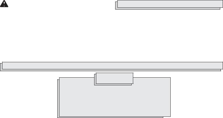
GROUNDING
WARNING!
Improperly connecting the grounding wire can result in the risk of electric shock. Check with a qualified electrician if you are in doubt as to whether the outlet is properly grounded. Do not modify the plug provided with the tool. Never remove the grounding prong from the plug. Do not use the tool if the cord or plug is damaged. If
damaged, have it repaired by a MILWAUKEE service facility before use. If the plug will not fit the outlet, have a proper outlet installed by a qualified electrician.
Grounded Tools:
Tools with Three Prong Plugs
Tools marked “Grounding Required” have a three wire cord and three prong grounding plug. The plug must be connected to a properly grounded outlet (See Figure A). If the tool should electrically malfunction or break down, grounding provides a low resistance path to carry electricity away from the user, reducing the risk of electric shock.
The grounding prong in the plug is connected through the green wire inside the cord to the grounding system in the tool. The green wire in the cord must be the only wire connected to the tool's grounding system and must never be attached to an electrically “live” terminal.
Your tool must be plugged into an appropriate outlet, properly installed and grounded in accordance with all codes and ordinances. The plug and outlet should look like those in Figure A.
Double Insulated Tools:
Tools with Two Prong Plugs
Tools marked “Double Insulated” |
|
|
|
not require grounding. They have a |
|
|
|
special double insulation system |
|
|
|
which satisfies OSHA requirements |
|
|
|
and complies with the applicable |
|
|
|
standards of Underwriters Labora- |
|
|
|
tories, Inc., the Canadian Standard |
|
|
|
Association and the National Electri- |
|
|
|
cal Code. Double Insulated tools may |
|
|
|
be used in either of the 120 volt out- |
Fig. B |
Fig. C |
|
lets shown in Figures B and C. |
|||
|
|
EXTENSION CORDS
Grounded tools require a three wire extension cord. Double insulated tools can use either a two or three wire extension cord. As the distance from the supply outlet increases, you must use a heavier gauge extension cord. Using extension cords with inadequately sized wire causes a serious drop in voltage, resulting in loss of power and possible tool damage. Refer to the table shown to determine the required minimum wire size.
The smaller the gauge number of the wire, the greater the capacity of the cord. For example, a 14 gauge cord can carry a higher current than a 16 gauge cord. When using more than one extension cord to make up the total length, be sure each cord contains at least the minimum wire size required. If you are using one extension cord for more than one tool, add the nameplate amperes and use the sum to determine the required minimum wire size.
Guidelines for Using Extension Cords
•If you are using an extension cord outdoors, be sure it is marked with the suffix “W-A” (“W” in Canada) to indicate that it is acceptable for outdoor use.
•Be sure your extension cord is properly wired and in good electrical condition. Always replace a damaged extension cord or have it repaired by a qualified person before using it.
•Protect your extension cords from sharp objects, excessive heat and damp or wet areas.
Recommended Minimum Wire Gauge
for Extension Cords*
Nameplate |
|
Extension Cord Length |
|
|||||
|
|
|
|
|
|
|
||
Amperes |
25' |
50' |
75' |
100' |
150' |
200' |
||
0 - 5 |
16 |
16 |
16 |
14 |
12 |
|
12 |
|
5.1 |
- 8 |
16 |
16 |
14 |
12 |
10 |
|
-- |
8.1 - 12 |
14 |
14 |
12 |
10 |
-- |
|
-- |
|
12.1 |
- 15 |
12 |
12 |
10 |
10 |
-- |
|
-- |
15.1 |
- 20 |
10 |
10 |
10 |
-- |
-- |
|
-- |
|
|
|
|
|
|
|
|
|
* Based on limiting the line voltage drop to five volts at 150% of the rated amperes.
READ AND SAVE ALL INSTRUCTIONS FOR
FUTURE USE.
page 5
OPERATION
WARNING!
To reduce the risk of injury, always unplug tool before attaching or removing accessories. Use only specifically recommended accessories. Others may be hazardous.
6.Press in the spindle lock button while using the open end wrench provided to tighten the hex bolt (clockwise).
NOTE: Tighten the bolt firmly enough to flatten the spring washer, but do not use excessive pressure. Overtightening the bolt may damage the wheel and flanges.
7.Allow the moveable portion of the guard to return to its original position.
Using the Hold-Down Chain
This tool is equipped with a hold-down chain which locks the handle down for transporting and storing the tool. To release the hold down chain, pull the handle down and lift the chain off the hook. To lock the chain, pull the handle down and loop the chain onto the hook.
WARNING!
To reduce the risk of injury, use only the proper wheel made for this machine. DO NOT USE ANY TYPE OF SAW BLADE.
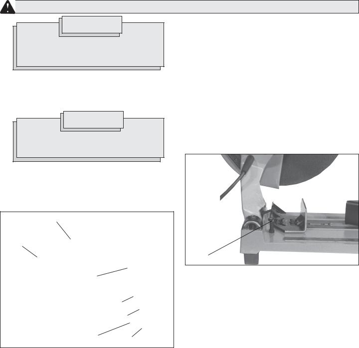
Removing and Installing Cut-Off Wheels (Fig. 1)
The cut-off machine is supplied with the abrasive cut-off wheel installed. MILWAUKEE recommends using only MILWAUKEE 14" Abrasive Cut-Off Wheels, 3/32" wide with this tool. Before operating the tool, make sure the wheel is in good condition as described in the “Specific
Safety Instructions for Abrasive Cut-Off Machines”.
Fig. 1 |
Moveable portion of guard |
Washer
Abrasive cut-off wheel
Flange
Washer
Spring |
|
washer |
Hex bolt |
To change wheels, follow the procedure below.
1.Release the hold down chain, pull the handle down and lift the chain off of the hook.
2.Pull the moveable portion of the guard back to expose the wheel arbor hex bolt.
Press in the spindle lock button and use the open end wrench provided to loosen the hex bolt (counterclockwise).
3.Remove the hex bolt, spring washer, washer, outer flange and cutoff wheel (if installed).
4.Check the two (2) wheel flanges to be sure they are in good condition. Remove any nicks or burrs, which could cause uneven cutting pressure and result in wheel damage.
5.Install the inner flange, wheel, outer flange, washer, spring washer and hex bolt as shown (Fig. 1).
8.Before starting a cut, step back from the tool and make a trial run to confirm that the wheel is in good condition. When replacing a cut-off wheel, run the tool for over 3 minutes. When starting routine work, run the tool for over 1 minute.
Adjusting the Depth of Cut (Fig. 2)
The depth adjustment bolt can be adjusted to change the depth of cut.
When adjusted properly, the depth adjustment bolt prevents the cut-off wheel from contacting the surface under the base during cutting. Cutoff wheels wear down as they are used and the depth of cut may need to be increased.
Fig. 2
Bolt
1.To adjust the depth of cut, use the open end wrench provided to lower or raise the depth adjustment bolt.
2.Loosen the hex nut.
3.Adjust the depth adjustment bolt to the desired height.
4.When desired depth of the cut is achieved, tighten the hex nut.
page 6
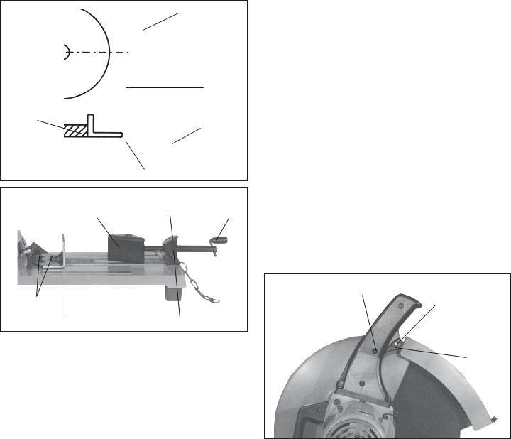
Supporting the Workpiece and Adjusting the Cut-Off Angle (Fig. 3 & 4)
Always use the vise and fence to hold the workpiece in place on the cutoff machine table. The vise plate moves forward and backward and adjusts to any angle. The fence also moves backward and forward and adjusts to any angle between 0° and 45° to the left or right.
When making cuts, the center line of the hub should contact approximately the midpoint of the workpiece and it should be approximately midway between the fence and vise as shown (Fig. 3).
Fig. 3
Cut-off wheel
Center line of hub
Vise plate
Fence
Workpiece
Fig. 4 |
Quick release |
|
|
Vise |
|
Vise plate |
lever |
handle |
Bolt
Fence
Vise
1.To adjust the fence, use the open end wrench provided to loosen (counterclockwise) the two bolts that hold the fence firmly in place
(Fig. 4).
Adjust the position and angle of the fence as desired.
Use the open end wrench provided to securely tighten (clockwise) the two bolts that hold the fence in place.
2.To adjust the vise, pull the quick release lever back to disengage it from the threads (Fig. 4).
Adjust the vise plate/vise handle depending on the workpiece size.
Push the quick release lever forward to engage the threads and lock the vise. To completely lock the assembly, turn the vise handle clockwise.
Selecting a Workpiece
The MILWAUKEE Abrasive Cut-Off Machine is designed to cut steel and concrete. It is not recommended for cutting wood. Do not attempt to install a saw blade on the tool.
Starting and Stopping the Tool
The tool operates at no load speed of 3900 RPM.
1.Plug in the tool.
2.To start the tool, pull trigger.
3.To stop the tool, release the trigger.
Locking Trigger Switch
The lock-on button, located next to the trigger switch, holds the trigger in the “ON” position for continuous full speed use.
1.To lock the trigger switch, push the lock-on button down while pulling the trigger. Release the trigger.
2.To unlock the trigger switch, pull the trigger and release.
Making a Cut
1.Unplug the tool.
2.Select a cutting angle and position the fence and vise assembly as needed. Follow the steps in “Supporting the Workpiece and Adjusting the Cut-Off Angle”.
3.Place the workpiece flat on top of the cut-off machine table. Turn the vise handle clockwise until the vise assembly holds the workpiece firmly in place.
4.Plug the tool in and pull the trigger. Allow the motor to reach full speed. Slowly lower the wheel into the workpiece.
NOTE: Always start the cut gently; do not bang or bump a wheel when starting the cut. For the safest and most efficient cutting, make sure that the cut-off wheel contacts the center of the workpiece.
5.When the cut is complete, raise the wheel completely from the workpiece before releasing the trigger and allowing the motor to stop.
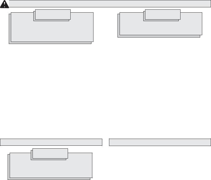
Trigger Hole Lock-Off Feature (Fig. 5)
The trigger hole allows the user to insert a padlock. This prevents the tool from being started unintentionally.
Fig. 5 |
Lock-on button |
|
Trigger hole
Trigger
page 7
MAINTENANCE
WARNING!
To reduce the risk of injury, always unplug your tool before performing any maintenance. Never disassemble the tool or try to do any rewiring on the tool's electrical system. Contact a MILWAUKEE service facility for ALL repairs.
WARNING!
To reduce the risk of injury, electric shock and damage to the tool, never immerse your tool in liquid or allow a liquid to flow inside the tool.
Cleaning
Maintaining Tools
Keep your tool in good repair by adopting a regular maintenance program. Before use, examine the general condition of your tool. Inspect guards, switches, tool cord set and extension cord for damage. Check for loose screws, misalignment, binding of moving parts, improper mounting, broken parts and any other condition that may affect its safe operation. If abnormal noise or vibration occurs, turn the tool off immediately and have the problem corrected before further use. Do not use a damaged tool. Tag damaged tools “DO NOT USE” until repaired (see “Repairs”).
Under normal conditions, relubrication is not necessary until the motor brushes need to be replaced. After six months to one year, depending on use, return your tool to the nearest MILWAUKEE service facility for the following:
Clean dust and debris from vents. Keep the tool handles clean, dry and free of oil or grease. Use only mild soap and a damp cloth to clean your tool since certain cleaning agents and solvents are harmful to plastics and other insulated parts. Some of these include: gasoline, turpentine, lacquer thinner, paint thinner, chlorinated cleaning solvents, ammonia and household detergents containing ammonia. Never use flammable or combustible solvents around tools.
Repairs
If your tool is damaged, return the entire tool to the nearest service center listed on the back cover of this operator’s manual.
•Lubrication
•Brush inspection and replacement
•Mechanical inspection and cleaning (gears, spindles, bearings, housing, etc.)
•Electrical inspection (switch, cord, armature, etc.)
•Testing to assure proper mechanical and electrical operation
ACCESSORIES
WARNING!
To reduce the risk of injury, always unplug the tool before attaching or removing accessories. Use only specifically recommended accessories. Others may be hazardous.
For a complete listing of accessories refer to your MILWAUKEE Electric
Tool catalog. To obtain a catalog, contact your local distributor or a service center listed on the back cover of this operator’s manual.
14" Abrasive Cut-Off Wheel
Same as supplied with the tool.
Open End Wrench
Same as supplied with the tool. Use the wrench to install and remove abrasive cut-off wheels and to adjust the fence and de[th adjustment bolt.
WARRANTY
Every MILWAUKEE tool is thoroughly inspected and tested before leaving our manufacturing facilities. Should any trouble develop, return the complete tool prepaid to our Corporate Office, Branch Office/Service
Center or nearest Authorized MILWAUKEE Service Station. If inspection shows the trouble is caused by defective workmanship or material, all repairs will be made without charge, and the tool will be returned, transportation prepaid. Battery packs for cordless tools are warranted for one year from the date of purchase.
This warranty does not apply where: (1) repairs or attempted repairs have been made by persons other than MILWAUKEE personnel or Authorized Service Station personnel; (2) repairs are required because of normal wear; (3) the tool has been abused or involved in an accident; (4) misuse is evident, such as caused by overloading the tool beyond its rated capacity; (5) the tool has been used after partial failure or (6) the tool has been used with an improper accessory. No other warranty, written or verbal, is authorized.
page 8
 Loading...