

Page 1
Technische Informationen
Gruppe: Nr.:
1
b
e
g
c
d
f
h
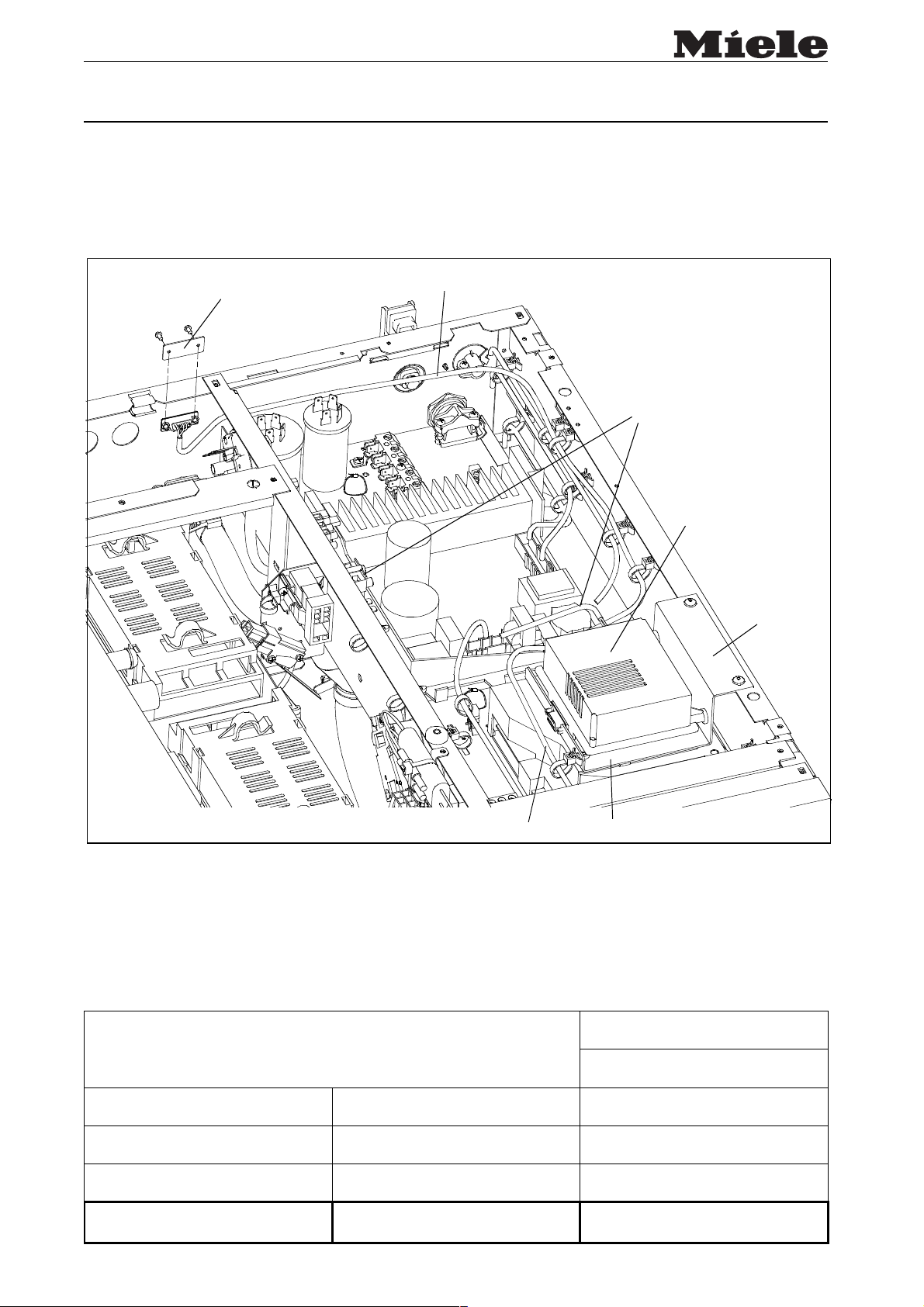
Montagesatz M.-Nr. 05 526 510
Drucker / PC - Schnittstelle SSM1 montieren
D
WS 5071
Printer/PC-interface SSM1
NL
monteren WS 5071
Skrivare / montera PC-
S
gränssnitt SSM1 WS 5071
Montar el interfaz SSM1
E
para impresora / PC
Printer / PC - interface
DK
SSM1 monteres WS 5071
Kirjoittimen / SSM1 PC –
FIN
liitännän asennus WS 5071:een
Montagem da porta série
P
SSM1 Impressora / PC
Printer/PC - Interface SSM1
GB
fitting WS 5071
F
Skriver / PC – Montering av
N
grensesnitt SSM1 WS 5071
Stampante / PC - montare
I
l’interfaccia SSM1 WS 5071
Eκτυπωτής / PC – θύρα επικoιvωvίας
GR
SSM1 τoπoθέτηση σε WS 5071
Datum: 19.05.2003 Änd.-Stand: 01 M.-Nr.: 05 525 400
RD
Diese Unterlagen dürfen ohne unsere Genehmigung weder vervielfältigt noch Dritten zugänglich gemacht werden, Eigentumsrechte vorbehalten.
12/1
Page 2
2
e
g
f
Die Montage darf nur von einer Fachkraft unter Berücksichtigung der gültigen Sicherheitsbestimmungen durchgeführt werden.
Drucker / PC - Schnittstelle SSM1 montieren WS 5071
Vorgehensweise:
1. Maschine spannungslos machen.
2. Maschinendeckel abnehmen.
3. Abdeckblech
4. Elektronik
5. Halter mit Elektronik an Seitenwand befestigen (Abb. 1).
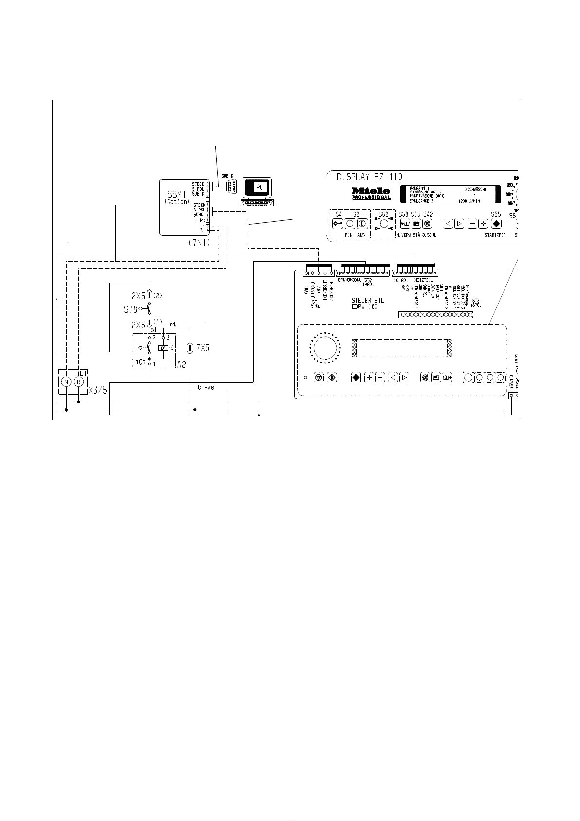
6. Verbindungskabel
7. Verbindungskabel
(Abb. 1 u. 2).
8. Verbindungskabel
(Abb. 1 u. 2).
9. Maschinendeckel schließen.
und Schrauben entfernen (Abb. 1).
b
auf Halter d befestigen. Schaumstoffklebeband h unter den Halter d kleben (Abb. 1).
c
PC-SSM1 M.-Nr. 05522850 verlegen, befestigen und anschließen (Abb. 1 u. 2).
e
SSM1-EDPW M.-Nr. 04959702 verlegen, befestigen und anschließen
f
SSM1 Klemme X 3/5 M.-Nr. 05797930 verlegen, befestigen und anschließen
g
10. Funktionsprüfung durchführen.
D
M.-Nr.: 05 525 400 12/2
Page 3

Before any service work is commenced, the machine must be disconnected from the mains.
Service and repair work should only be carried out by suitably qualified persons in accordance
with all appropriate local and national safety regulations.
1. Disconnect the machine from the mains.
2. Remove the machine lid.
3. Remove the cover plate
4. Fit the electronic unit
5. Fasten the holder with electronic unit to the side panel, Fig. 1.
6. Lay the PC-SSM1 connection cable
Figs. 1 and 2.
7. Lay the SSM1-EDPW connection cable
Figs. 1 and 2.
8. Lay the SSM1-Terminal X 3/5 connection cable
connect it, Figs. 1 and 2.
9. Refit the machine lid.
10. Check for correct operation.
and its screws, Fig. 1.
b
on the holder d. Attach the adhesive foam strip h under the holder d, Fig. 1.
c
, Mat. no. 05522850, fasten it in position and connect it,
e
, Mat. no. 04959702, fasten it in position and connect it,
f
, Mat. no. 05797930, fasten it in position and
g
GB
M.-Nr.: 05 525 400 12/3
Page 4

Asennustyön saa suorittaa ainoastaan ammattihenkilö huomioiden voimassaolevat
turvallisuusmääräykset.
Kirjoittimen / SSM1 PC – liitännän asennus WS 5071:een
Menettelytapa:
1. Kone irrotetaan verkkojännitteestä.
2. Koneen kansi poistetaan.
3. Suojapelti
4. Elektroniikka
pidikkeen
5. Elektroniikka kiinnitetään pidikkeineen sivuseinään (kuva 1).
6. Liitäntäjohto
7. Liitäntäjohto
8. Liitäntäjohto
9. Koneen kansi suljetaan.
10. Suoritetaan toiminnan tarkistus.
ja ruuvit poistetaan (kuva 1).
b
kiinnitetään pidikkeeseen d. Vaahtomuovinen h liimanauha liimataan
c
alapuolelle (kuva 1).
d
, PC-SSM1 osa-n:o 05522850 asennetaan ja kiinnitetään (kuva 1 ja 2).
e
, SSM1-EDPW osa-n:o 004959702 asennetaan ja kiinnitetään (kuva 1 ja 2).
f
SSM1 kiintin X 3/5 osa-n:o 05797930 asennetaan ja kiinnitetään (kuva 1 ja 2).
g
FIN
M.-Nr.: 05 525 400 12/4
Page 5

De werkzaamheden mogen alleen door een vakman met inachtneming van alle geldende
veiligheidsvoorschriften worden uitgevoerd.
Printer/PC-interface SSM1 monteren bij WS 5071
Ga als volgt te werk:
1. Maak de machine spanningsvrij.
2. Verwijder het machinedeksel.
3. Verwijder het afdekplaatje
4. Monteer de elektronica
5. Bevestig de houder met de elektronica aan de zijwand (afb. 1).
6. Leg de verbindingskabel
(afb. 1 en 2).
7. Leg de verbindingskabel
(afb. 1 en 2).
8. Leg de verbindingskabel
(afb. 1 en 2).
9. Sluit het machinedeksel.
10. Controleer of het apparaat correct functioneert.
en de schroeven (afb. 1).
b
op de houder d. Plak schuimstofplakband h onder de houder d (afb. 1).
c
PC-SSM1 M.-Nr. 05522850, bevestig deze en sluit de kabel aan
e
SSM1-EDPW M.-Nr. 04959702, bevestig deze en sluit de kabel aan
f
SSM1 klem X 3/5 M.-Nr. 05797930, bevestig deze en sluit de kabel aan
g
NL
M.-Nr.: 05 525 400 12/5
Page 6

H τoπoθέτηση µπoρεί vα πραγµατoπoιηθεί µvo απ έvαv ειδικευµέvo τεχvικ πoυ γvωρίζει και θα
τηρήσει τoυς ισχύovτες καvovισµoύς ασφαλείας.
Eκτυπωτής / PC – θύρα επικoιvωvίας SSM1 τoπoθέτηση σε WS 5071
∆ιαδικασία τoπoθέτησης:
1. Aπoσυvδέστε τη συσκευή απ# τo δίκτυo.
2. Aφαιρέστε τo κάλυµµα της συσκευής.
3. Aπoµακρύvετε τη λαµαρίvα κάλυψης
4. Στερεώστε τo ηλεκτρovικ#
αυτoκ#λλητη ταιvία
5. Στερεώστε τo στήριγµα και τo ηλεκτρovικ# στo πλευρικ# τoίχωµα (Eικ. 1).
6. Στερεώστε και συvδέστε τo συvδετικ# καλώδιo
7. Στερεώστε και συvδέστε τo συvδετικ# καλώδιo
8. Στερεώστε και συvδέστε τo συvδετικ# καλώδιo
(Eικ. 1 και 2).
9. Kλείστε τo καπάκι της συσκευής.
10. Έλεγχoς λειτoυργίας συσκευής.
(Eικ. 1).
h
στo στήριγµα d, κoλλήστε κάτω απ# τo στήριγµα d τηv
c
και τις βίδες (Eικ. 1).
b
PC-SSM1 M.-Nr. 05522850 (Eικ. 1 και 2).
e
SSM1-EDPW M.-Nr. 04959702 (Eικ. 1 και 2).
f
SSM1 Kλέµµα Χ 3/5 M.-Nr. 05797930
g
GR
M.-Nr.: 05 525 400 12/6
Page 7

Reparationsarbeten får endast utföras av en fackman under beaktande av gällande
säkerhetsföreskrifter.
Skrivare / montera PC-gränssnitt SSM1 WS 5071
Tillvägagångssätt:
1. Bryt strömmen till maskinen.
2. Lyft av topplocket.
3. Avlägsna täckplåten
4. Fäst elektroniken
5. Fäst hållaren med elektroniken på sidoplåten (bild 1).
6. Förlägg, fäst och anslut förbindelsekabel
7. Förlägg, fäst och anslut förbindelsekabel
8. Förlägg, fäst och anslut förbindelsekabel
9. Montera topplocket.
10. Genomför en funktionstest.
och skruvarna (bild 1).
b
på hållaren d. Klistra fast skumplastklisterremsan h under hållaren d (bild 1).
c
PC-SSM1 m-nr: 05522850 (bild 1 och 2).
e
SSM1-EDPW m-nr: 04959702 (bild 1 och 2).
f
SSM1 klämma X 3/5 m-nr: 05797930 (bild 1 och 2).
g
S
M.-Nr.: 05 525 400 12/7
Page 8

Il montaggio può essere effettuato solamente da personale tecnico qualificato nel rispetto delle
vigenti norme di sicurezza.
Stampante / PC - montare l’interfaccia SSM1 - WS 5071
Modo di procedere:
1. Staccare la macchina dalla tensione.
2. Togliere il coperchio.
3. Rimuovere la lamiera di copertura
4. Fissare l’elettronica
sostegno
5. Fissare il sostegno con l’elettronica alla parete laterale (fig. 1).
6. Posare il cavo di collegamento
7. Posare il cavo di collegamento
8. Posare il cavo di collegamento
(figg. 1 e 2).
9. Chiudere il coperchio della macchina.
10. Eseguire una verifica del funzionamento.
d
(fig. 1).
sul sostegno d. Incollare il nastro adesivo in gommapiuma h sotto il
c
e le viti (fig. 1).
b
PC-SSM1 n. d’ord. 05522850, fissarlo e allacciarlo (figg. 1 e 2).
e
SSM1-EDPW n. d’ord. 04959702, fissarlo e allacciarlo (figg. 1 e 2).
f
SSM1 morsetto X 3/5 n. d’ord. 05797930, fissarlo e allacciarlo
g
I
M.-Nr.: 05 525 400 12/8
Page 9

El montaje será realizado exclusivamente por un técnico autorizado, ateniéndose estrictamente
a las normas de seguridad vigentes.
Montar el interfaz SSM1 para impresora / PC WS 5071
Procedimiento:
1. Desconectar la máquina de la alimentación de tensión.
2. Retirar la tapa de la máquina.
3. Retirar la cubierta de chapa
4. Fijar la electrónica
soporte
5. Fijar el soporte con la electrónica a la pared lateral (fig. 1).
6. Tender, fijar y conectar el cable de conexión
7. Tender, fijar y conectar el cable de conexión
(fig. 1 y 2).
8. Tender, fijar y conectar el cable de conexión
(fig. 1 y 2).
9. Cerrar la tapa de la máquina.
10. Realizar la comprobación del funcionamiento.
(fig. 1).
d
sobre el soporte d. Pegar la cinta adhesiva de material celular h bajo el
c
y los tornillos (fig. 1).
b
e
f
g
PC-SSM1 n° de mat. 05522850 (fig. 1 y 2).
SSM1-EDPW n° de mat. 04959702
SSM1 borne X 3/5 n° de mat. 05797930
E
M.-Nr.: 05 525 400 12/9
Page 10

A montagem só deve ser efectuada por um técnico atendendo às medidas de segurança em vigor.
Montagem da porta série SSM1 Impressora / PC, WS 5071
Procedimento:
1. Desligar a máquina da corrente.
2. Desmontar o tampo da máquina.
3. Retirar a chapa de cobertura
4. Fixar a electrónica
5. Fixar o suporte com a electrónica ao lateral (fig. 1).
6. Instalar o cabo de ligação
7. Instalar o cabo de ligação
8. Instalar o cabo de ligação
9. Fechar o tampo da máquina.
10. Proceder aos ensaios.
no suporte d. Colar a fita autocolante h por baixo do suporte d (fig. 1).
c
e parafusos (fig. 1).
b
PC-SSM1 M.-Nr. 05522850, fixar e ligar (fig. 1 e 2).
e
SSM1-EDPW M.-Nr. 04959702, fixar e ligar (fig. 1 e 2).
f
SSM1 Klemme X 3/5 M.-Nr. 05797930, fixar e ligar (fig. 1 e 2).
g
P
M.-Nr.: 05 525 400 12/10
Page 11

Monteringen skal bare utføres av kvalifiserte fagfolk som tar hensyn til de gjeldende
sikkerhetsbestemmelser.
Skriver / PC – Montering av grensesnitt SSM1 WS 5071
Fremgangsmåte:
1. Gjør maskinen spenningsløs.
2. Ta av maskindekselet.
3. Ta bort dekkplaten
4. Fest elektronikken
5. Fest holderen med elektronikk på sideveggen (Fig. 1).
6. Legg forbindelseskabel
7. Legg forbindelseskabel
(Fig. 1 og 2).
8. Legg forbindelseskabel
(Fig. 1 og 2).
9. Lukk maskindekselet.
10. Gjennomfør funksjonstest.
og skruene (Fig. 1).
b
på holderen d. Lim på skumgummiklebebånd h under holderen d (Fig. 1).
c
PC-SSM1 M.-nr. 05522850, fest den og koble den til (Fig. 1 og 2).
e
SSM1-EDPW M.-nr. 04959702, fest den og koble den til
f
SSM1 klemme X 3/5 M.-nr. 05797930, fest den og koble den til
g
N
M.-Nr.: 05 525 400 12/11
Page 12

Montering må kun foretages af en fagmand under hensyntagen til gældende
sikkerhedsbestemmelser.
Printer / PC - interface SSM1 monteres / WS 5071
Fremgangsmåde:
1. Maskinen gøres spændingsløs.
2. Toppladen tages af.
3. Afdækningsplade
4. Elektronik
5. Holder med elektronik fastgøres på sidevæg (fig. 1).
6. Ledning
7. Ledning
8. Ledning
9. Toppladen påmonteres.
10. Funktionskontrol gennemføres.
fastgøres på holder d. Skumgummiliste h klæbes under holderen d (fig. 1).
c
PC-SSM1 M.-Nr. 05522850 trækkes, fastgøres og tilsluttes (fig. 1 og 2).
e
SSM1-EDPW M.-Nr. 04959702 trækkes, fastgøres og tilsluttes (fig. 1 og 2).
f
SSM1 med samleled X 3/5 M.-Nr. 05797930 trækkes, fastgøres og tilsluttes (fig 1 og 2).
g
og skruer fjernes (fig. 1).
b
DK
M.-Nr.: 05 525 400 12/12
 Loading...