

Page 1
IC equipment
IC equipment: Inline-Ultrafiltration (6.5330.110)
Manual
8.110.8037EN / 2014-02-20
Page 2

Page 3

Metrohm AG
CH-9100 Herisau
Switzerland
Phone +41 71 353 85 85
Fax +41 71 353 89 01
info@metrohm.com
www.metrohm.com
IC equipment
IC equipment: Inline-Ultrafiltration
(6.5330.110)
8.110.8037EN / 2014-02-20
Manual
zst
Page 4

Teachware
Metrohm AG
CH-9100 Herisau
teachware@metrohm.com
This documentation is protected by copyright. All rights reserved.
Although all the information given in this documentation has been
checked with great care, errors cannot be entirely excluded. Should you
notice any mistakes please send us your comments using the address
given above.
Documentation in additional languages can be found on
http://documents.metrohm.com.
Page 5

■■■■■■■■■■■■■■■■■■■■■■
Table of contents
1 Introduction 1
1.1 Description of the IC equipment: Inline-Ultrafiltration ..... 1
1.2 About the documentation ................................................... 1
1.3 Symbols and conventions .................................................... 2
2 Overview 3
2.1 Parts of the IC equipment: Inline-Ultrafiltration ................ 3
2.2 Components of the ultrafiltration cell ................................ 3
2.3 Connectors of the ultrafiltration cell .................................. 4
2.4 Mode of operation for ultrafiltration .................................. 5
3 Installation 6
Table of contents
3.1 Preparing the ultrafiltration cell .......................................... 6
3.2 Connecting the ultrafiltration cell ..................................... 11
3.3 Inserting the ultrafiltration cell ......................................... 14
3.4 Deaerating the ultrafiltration cell ..................................... 16
4 Operation and maintenance 18
4.1 Operation ............................................................................ 18
4.1.1 Service life of the filtration membrane .................................... 18
4.1.2 Selecting the filtration membrane .......................................... 19
4.2 Maintenance ....................................................................... 20
5 Technical specifications 22
5.1 Ultrafiltration cell (6.2729.110) ......................................... 22
5.2 Filtration membrane (6.2714.020) .................................... 22
5.3 Dialysis membrane (6.2714.030) ....................................... 22
6 Accessories 23
Index 25
IC equipment: Inline-Ultrafiltration
■■■■■■■■
III
Page 6

Table of figures
Table of figures
Figure 1 IC equipment: Inline-Ultrafiltration – Parts ......................................... 3
Figure 2 Ultrafiltration cell – Parts ................................................................... 3
Figure 3 Ultrafiltration cell – Connectors ......................................................... 4
Figure 4 Connecting the ultrafiltration cell ..................................................... 11
■■■■■■■■■■■■■■■■■■■■■■
■■■■■■■■
IV
IC equipment: Inline-Ultrafiltration
Page 7

■■■■■■■■■■■■■■■■■■■■■■
1 Introduction
1 Introduction
1.1 Description of the IC equipment: Inline-Ultrafiltration
The IC equipment: Inline-Ultrafiltration (6.5330.110) contains all accessories required for Inline Ultrafiltration of difficult samples directly before
injection.
The main component of the IC equipment: Inline-Ultrafiltration is the
high-performance ultrafiltration cell. This cell is suitable for the filtration of
samples that pose particular requirements with regard to filtration effectiveness and sample throughput.
The two channels of a peristaltic pump are required for pumping the sample and the filtrate.
1.2 About the documentation
This manual describes the correct assembly and maintenance of the IC
equipment: Inline-Ultrafiltration, the installation of the capillary connections to and from the ultrafiltration cell and how to mount the holder on
both the Sample Processor and the IC instrument.
The installation of the peristaltic pump is not described in this manual. This
description can be found in the respective manuals for the ion chromatograph or the Sample Processor.
CAUTION
Please read through this documentation carefully before putting the IC
equipment: Inline-Ultrafiltration into operation. The documentation
contains information and warnings which the user must follow in order
to ensure safe operation of the IC equipment: Inline-Ultrafiltration.
IC equipment: Inline-Ultrafiltration
■■■■■■■■
1
Page 8
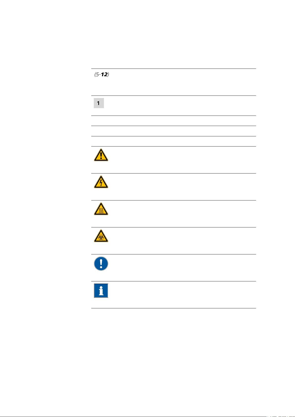
1.3 Symbols and conventions
1.3 Symbols and conventions
The following symbols and formatting may appear in this documentation:
Cross-reference to figure legend
The first number refers to the figure number, the second to the instrument part in the figure.
Instruction step
Carry out these steps in the sequence shown.
Method Dialog text, parameter in the software
File ▶ New Menu or menu item
[Next] Button or key
WARNING
This symbol draws attention to a possible life-threatening hazard or risk of injury.
■■■■■■■■■■■■■■■■■■■■■■
WARNING
This symbol draws attention to a possible hazard due
to electrical current.
WARNING
This symbol draws attention to a possible hazard due
to heat or hot instrument parts.
WARNING
This symbol draws attention to a possible biological
hazard.
CAUTION
This symbol draws attention to possible damage to
instruments or instrument parts.
NOTE
This symbol highlights additional information and
tips.
■■■■■■■■
2
IC equipment: Inline-Ultrafiltration
Page 9
■■■■■■■■■■■■■■■■■■■■■■
2 Overview
2.1 Parts of the IC equipment: Inline-Ultrafiltration
2 Overview
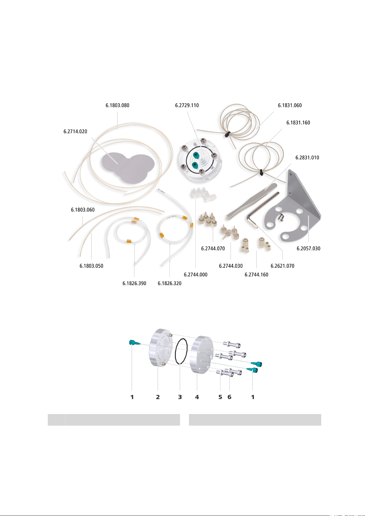
Figure 1 IC equipment: Inline-Ultrafiltration – Parts
2.2 Components of the ultrafiltration cell
Stoppers
1
IC equipment: Inline-Ultrafiltration
Figure 2
Ultrafiltration cell – Parts
Upper chamber
2
■■■■■■■■
3
Page 10
2.3 Connectors of the ultrafiltration cell
■■■■■■■■■■■■■■■■■■■■■■
Sealing ring
3
Washers
5
Lower chamber
4
Screws
6
For joining the upper and the lower part of
the cell.
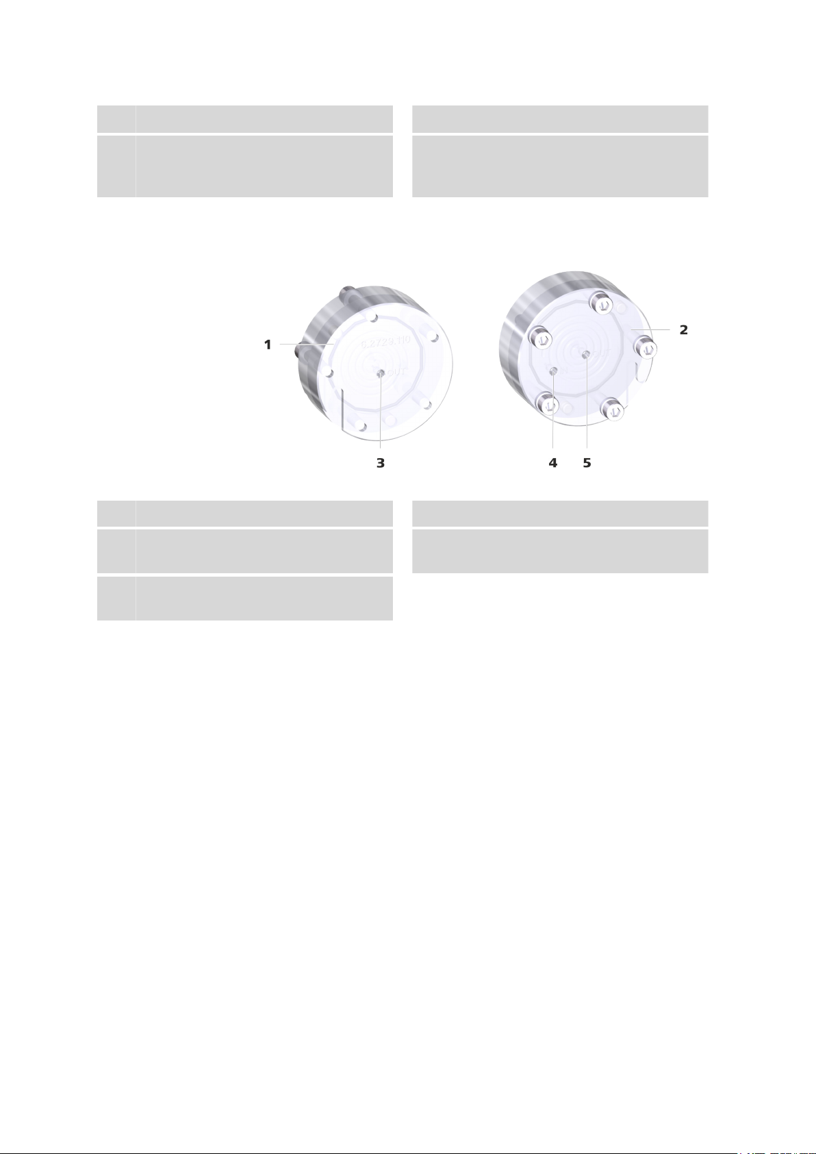
2.3 Connectors of the ultrafiltration cell
Figure 3 Ultrafiltration cell – Connectors
Upper chamber
1
Lower chamber
2
Filtrate outlet
3
Labeled OUT.
Sample outlet
5
Labeled OUT.
Sample inlet
4
Labeled IN.
■■■■■■■■
4
IC equipment: Inline-Ultrafiltration
Page 11

■■■■■■■■■■■■■■■■■■■■■■
2.4 Mode of operation for ultrafiltration
2 Overview
The peristaltic pump delivers a continuous flow of sample solution at a
high rate through the lower chamber of the ultrafiltration cell. The sample
flows along the filtration membrane and then to the waste container.
At the same time, the peristaltic pump's second channel generates a vacuum in the upper chamber of the ultrafiltration cell, thus pulling the sample solution through the filtration membrane. The filtrate reaches the sample loop and is then injected.
Less than 20% of the original sample solution volume is analyzed as filtrate. The remainder flows directly into the waste container.
IC equipment: Inline-Ultrafiltration
■■■■■■■■
5
Page 12

3.1 Preparing the ultrafiltration cell
3 Installation
This chapter describes how to assemble the ultrafiltration cell, how to fasten the ultrafiltration cell to the Sample Processor or in the ion chromatograph and how to connect the ultrafiltration cell to the peristaltic pump
and the injection valve.
Depending on the device combination, the ultrafiltration cell may be
placed at different locations. Please observe the following recommendations:
Devices Peristaltic pump Ultrafiltration cell
■■■■■■■■■■■■■■■■■■■■■■
Sample Processor with
peristaltic pump and ion
chromatograph
Only ion chromatograph,
type Prep 1
Only ion chromatograph
with peristaltic pump
on the Sample Processor on the Sample Processor
on the ion chromatograph on the ion chromatograph
on the ion chromatograph in the detector chamber of
3.1 Preparing the ultrafiltration cell
You have to insert a filtration membrane (6.2714.020) before you can
insert the ultrafiltration cell.
the ion chromatograph
with cell holder
(6.2057.120)
■■■■■■■■
6
IC equipment: Inline-Ultrafiltration
Page 13

■■■■■■■■■■■■■■■■■■■■■■
Inserting the filtration membrane
Required tools ■ Ultrafiltration cell (6.2729.110)
■ Filtration membrane (6.2714.020)
■ Hex key (6.2621.070)
■ Tweezers (6.2831.010)
1
Removing the stoppers
3 Installation
■ Remove the three green stoppers.
■ Turn the ultrafiltration cell around and place it on a table. The
screws face upwards.
2
Removing the screws
■ Loosen the screws with the hex key.
■ Remove the screws with the washers and put them aside.
IC equipment: Inline-Ultrafiltration
■■■■■■■■
7
Page 14
3.1 Preparing the ultrafiltration cell
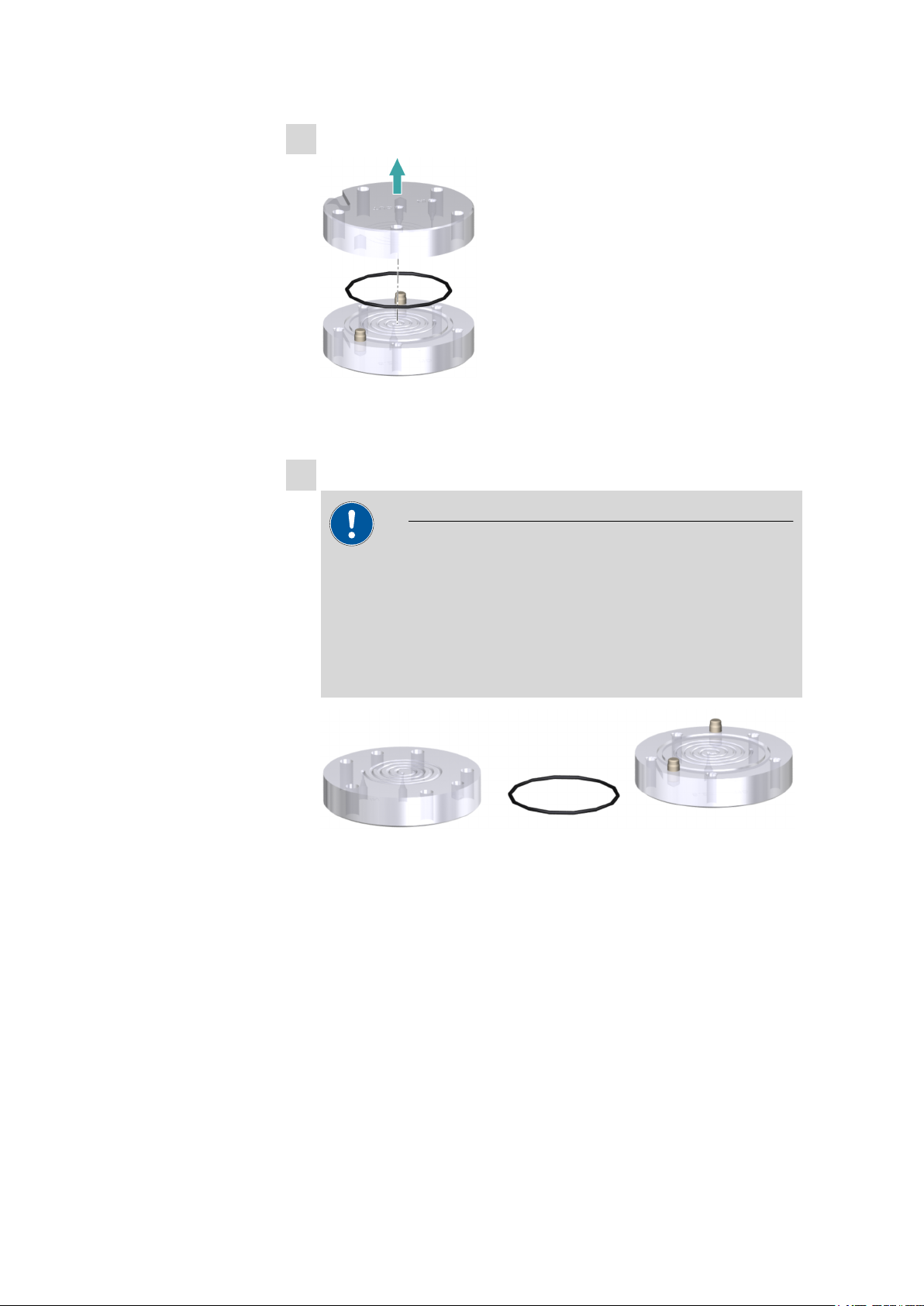
3
Disassembling the ultrafiltration cell
■ Remove the upper part of the ultrafiltration cell.
■ Remove the sealing ring.
4
Cleaning the ultrafiltration cell
CAUTION
■■■■■■■■■■■■■■■■■■■■■■
Damage to the ultrafiltration cell
Organic solvents (e.g. acetone) corrode and damage the ultrafiltration cell material (PMMA).
■ Use only ultrapure water or a water-ethanol mixture (70:30) for
cleaning the ultrafiltration cell.
■ Thoroughly rinse off the sealing ring (2-3), the upper chamber
(2-2) and the lower chamber (2-4) of the ultrafiltration cell with
ultrapure water.
■ Dry all parts with a lint-free cloth.
■■■■■■■■
8
IC equipment: Inline-Ultrafiltration
Page 15

■■■■■■■■■■■■■■■■■■■■■■
5
Wetting the filtration membrane
NOTE
In the package containing the filtration membranes, you will find
sheets of different thicknesses and colors:
■ The firm white cardboard is a cover protecting the filtration
membranes. Do not place it in the ultrafiltration cell.
■ The thin light-blue sheets are separation sheets placed between
two filtration membranes. Do not place them in the ultrafiltration cell.
■ The thin white sheets are the filtration membranes. Use only
these for ultrafiltration.
3 Installation
■ Using the tweezers, take a new filtration membrane out of the
package.
■ Place the filtration membrane in a petri dish filled with ultrapure
water and allow to hydrate for approx. two minutes.
6
Inserting the filtration membrane
NOTE
Make sure that the water-soaked filtration membrane does not dry
out before it is inserted, as it can otherwise no longer be used!
Place the sealing ring back in the recess.
■
■ Using the tweezers, place the wet filtration membrane centrally
inside the sealing ring onto the cell.
IC equipment: Inline-Ultrafiltration
■■■■■■■■
9
Page 16

3.1 Preparing the ultrafiltration cell
■■■■■■■■■■■■■■■■■■■■■■
7
Assembling the ultrafiltration cell
■ Place the upper part of the ultrafiltration cell on the lower part in
such a way that the two guide bolts fit exactly into the two bore
holes.
8
Screwing the ultrafiltration cell together
■■■■■■■■
10
■ Screw the five screws with the washers in the ultrafiltration cell by
hand first.
■ Then firmly tighten them with the hex key in crosswise sequence.
IC equipment: Inline-Ultrafiltration
Page 17

■■■■■■■■■■■■■■■■■■■■■■
3.2 Connecting the ultrafiltration cell
This chapter describes how to establish the capillary connections of the filtration system (regardless of whether the filtration cell is installed on the
Sample Processor or in the ion chromatograph). It does not, however,
describe the tubing configuration for the peristaltic pump. Please refer to
the chapter "Installing the peristaltic pump" in the manual for the Sam-
ple Processor or the ion chromatograph for this information.
The following figure shows a schematic overview of all capillary connections of the filtration system.
3 Installation
Required accessories
Figure 4
Connecting the ultrafiltration cell
NOTE
■ In order to keep dead volume to a minimum, make sure that the
capillaries are as short as possible.
■ The capillaries that are used for transferring the filtrate are thinner
than the capillaries used for transferring the sample.
■ To prevent the capillaries leading into the ion chromatograph from
being pinched, always guide them through the capillary feedthroughs provided for this purpose (see the manual for the ion chro-
matograph).
Connecting the ultrafiltration cell
■ Ultrafiltration cell (6.2729.110)
■ PTFE capillary, 0.5 mm ID / 20 cm (6.1803.050)
■ PTFE capillary, 0.97 mm ID / 20 cm (6.1803.060)
■ PTFE capillary, 0.97 mm ID / 1 m (6.1803.080)
IC equipment: Inline-Ultrafiltration
■■■■■■■■
11
Page 18

3.2 Connecting the ultrafiltration cell
■ Pump tubing LFL (orange/yellow), 3 stoppers (6.1826.320)
■ Pump tubing LFL (yellow/yellow), 3 stoppers (6.1826.390)
■ PEEK capillary, 0.5 mm ID / 1 m (6.1831.060)
■ PEEK capillary, 0.5 mm ID / 70 cm (6.1831.160)
■ Pressure screw PVDF (6.2744.000)
■ Coupling olive/UNF 10/32 (6.2744.030)
■ Pressure screw, short (6.2744.070)
■ Pump tubing connection with locking nut (6.2744.160)
■■■■■■■■■■■■■■■■■■■■■■
1
Preparing the pump tubing for the sample
Use the pump tubing with yellow stoppers (6.1826.390) for conveying the sample.
■ Attach the coupling olive/UNF 10/32 (6.2744.030) to the inlet.
■ Attach the pump tubing connection with locking nut
(6.2744.160) to the outlet (see chapter "Installing the peristaltic
pump" in the manual for the ion chromatograph or in the manual for the Sample Processor).
2
Preparing the pump tubing for the filtrate
Use the pump tubing with orange/yellow stoppers (6.1826.320) for
conveying the filtrate.
■ Attach the coupling olive/UNF 10/32 (6.2744.030) to the inlet.
■ Attach the pump tubing connection with locking nut
(6.2744.160) to the outlet (see chapter "Installing the peristaltic
pump" in the manual for the ion chromatograph or in the manual for the Sample Processor).
3
Connecting the capillaries to the pump tubing for the sample
■ Tighten the PEEK capillary (6.1831.160) to the inlet of the pump
tubing with yellow stoppers (6.1826.390) using a pressure screw
(6.2744.070).
■ Tighten the PTFE capillary (6.1803.060) to the outlet of the pump
tubing with yellow stoppers (6.1826.390) using a pressure screw
(6.2744.070).
■■■■■■■■
12
IC equipment: Inline-Ultrafiltration
Page 19

■■■■■■■■■■■■■■■■■■■■■■
3 Installation
4
Connecting the capillaries to the pump tubing for the filtrate
■ Tighten the PTFE capillary (6.1803.050) to the inlet of the pump
tubing with orange/yellow stoppers (6.1826.320) using a pressure
screw (6.2744.070).
■ Tighten the PEEK capillary (6.1831.060) to the outlet of the pump
tubing with orange/yellow stoppers (6.1826.320) using a pressure
screw (6.2744.070).
5
Connecting capillaries to the ultrafiltration cell
CAUTION
Use only PVDF pressure screws (6.2744.000) to tighten capillaries
to the ultrafiltration cell.
PEEK pressure screws are too hard and could damage the ultrafiltration cell material.
■ Tighten the PTFE capillary (6.1803.060) to the inlet labeled IN of
the ultrafiltration cell's lower chamber using a PVDF pressure
screw (6.2744.000).
■ Tighten the PTFE capillary (6.1803.080) to the outlet labeled OUT
of the ultrafiltration cell's lower chamber using a PVDF pressure
screw (6.2744.000).
IC equipment: Inline-Ultrafiltration
■■■■■■■■
13
Page 20

3.3 Inserting the ultrafiltration cell
■ Tighten the PTFE capillary (6.1803.050) to the outlet labeled OUT
of the ultrafiltration cell's upper chamber using a PVDF pressure
screw (6.2744.000).
6
Connecting the remaining capillaries
■ Tighten the free end of the PEEK capillary (6.1831.160) to the
needle of the Sample Processor (see manual for the Sample Processor).
■ Tighten the free end of the PEEK capillary (6.1831.060) to Port 1
of the injection valve in the ion chromatograph (see manual for
the ion chromatograph).
■ Either tighten the free end of the PTFE capillary (6.1803.080) to
the waste collector or guide it directly to the waste container and
tighten it there.
3.3 Inserting the ultrafiltration cell
The ultrafiltration cell can be fastened either to the Sample Processor or in
the ion chromatograph.
■■■■■■■■■■■■■■■■■■■■■■
Required accessories
Fastening the ultrafiltration cell to the Sample Processor
■ Filtration cell holder (6.2057.030)
■ Ultrafiltration cell (6.2729.110)
1
Attaching the holder
Tighten the filtration cell holder (6.2057.030) to the IC Sample Processor (see manual for the IC Sample Processor).
2
Inserting the ultrafiltration cell
■■■■■■■■
14
IC equipment: Inline-Ultrafiltration
Page 21

■■■■■■■■■■■■■■■■■■■■■■
■ Insert the ultrafiltration cell in such way that the screw heads are
located in the holes in the filtration cell holder provided for this
purpose.
Inserting the ultrafiltration cell in the ion chromatograph
Required accessories ■ Filtration cell holder (6.2057.140)
■ Ultrafiltration cell (6.2729.110)
1
Hanging in the holder
3 Installation
■ Hang the filtration cell holder (6.2057.140) in the holding device
in the ion chromatograph provided for this purpose.
2
Inserting the ultrafiltration cell
■ Insert the ultrafiltration cell in such way that the screw heads are
located in the holes in the filtration cell holder provided for this
purpose.
IC equipment: Inline-Ultrafiltration
■■■■■■■■
15
Page 22

3.4 Deaerating the ultrafiltration cell
3.4 Deaerating the ultrafiltration cell
Every time a new filtration membrane is inserted, the air which may still be
present in the filtration cell and in the capillaries must be removed. To
accomplish this, rinse out all capillaries with e.g. ultrapure water.
NOTE
The entire filtration system must be completely connected prior to the
rinsing procedure.
Rinsing the ultrafiltration cell
1
Settings in the software
■ Immerse the needle of the Sample Processor into the rinsing solu-
tion.
■ Switch on the peristaltic pump.
■ Rinse the filtration system with ultrapure water for approx. 5 min.
2
Monitoring the rinsing process
■ Check whether equal amounts of solution are emerging from
both feed lines to the waste container.
■ Check whether all the capillary connections from the rinsing solu-
tion through the peristaltic pump and the ultrafiltration cell are
leak-tight all the way to the waste container.
If liquid is escaping somewhere, then tighten the corresponding
connection or redo the connection.
■■■■■■■■■■■■■■■■■■■■■■
■■■■■■■■
16
IC equipment: Inline-Ultrafiltration
Page 23

■■■■■■■■■■■■■■■■■■■■■■
3 Installation
■ Check whether any air bubbles remain trapped in the ultrafiltra-
tion cell.
If air bubbles are trapped in the cell, then unscrew the PTFE capillaries from the filtrate outlet (3-3) and from the sample outlet
(3-5) and wait until the air bubbles have escaped. Afterwards,
tighten the capillaries to the ultrafiltration cell again.
IC equipment: Inline-Ultrafiltration
■■■■■■■■
17
Page 24

4.1 Operation
4 Operation and maintenance
4.1 Operation
4.1.1 Service life of the filtration membrane
One of the most commonly encountered problems in filtration is that solid
substances in the sample are deposited on the filtration membrane, causing it to become blocked over time. The ultrafiltration cell has been
designed so as to prevent this effect to the extent possible. It has a symmetrical design and is placed horizontally in the Sample Processor or in the
ion chromatograph. The sample flows through the lower chamber of the
ultrafiltration cell and the filtrate is aspirated from the top. In this way,
solid substances adhere less to the membrane.
Nevertheless, depending on the level and type of contamination in the
sample, the filtration process must be monitored and the filtration membrane replaced if necessary.
■■■■■■■■■■■■■■■■■■■■■■
A declining recovery rate in standard solution analyses is an indicator for
an imminent blockage of a filtration membrane. These standard solutions
should ideally be prepared with the sample matrix to be analyzed.
If a large number of samples is analyzed, we recommend measuring check
standards regularly (in the case of samples with high particle loads, after
every 5th to 10th sample). No general prediction regarding the number of
filtration cycles can be made. Also, the change in the recovery rate may be
different with more samples being analyzed. Whereas the recovery rate
with one sample matrix may remain constant over many samples and then
suddenly drop off severely, its decline may be slow and continuous with a
different sample composition.
At which time a filtration membrane needs to be replaced depends on the
sample matrix and the specifications of the analysis method applied. Experience has shown that minuscule particles and suspended substances in
the sample matrix will lead to blockage of the filtration membrane faster
than coarser particles will, because the latter will be more readily propelled past the membrane in the flow of sample material.
The following table lists some sample types that were filtered with the
ultrafiltration cell (6.2729.110) and a filtration membrane (6.2714.020)
with a pore size of 0.2 µm and subsequently analyzed on a Metrohm ion
chromatograph. The concentration of the following seven anions was
determined for each sample type: F–, Cl–, NO
–
, Br–, NO
2
–
, HPO
3
2–
4
, SO
2–
.
4
■■■■■■■■
18
IC equipment: Inline-Ultrafiltration
Page 25

■■■■■■■■■■■■■■■■■■■■■■
4 Operation and maintenance
Table 1 Filtration of various samples
Sample designation Number of samples per filter
Orange juice with fruit pulp 40
Surface water 500
Drinking water 1,000
Ground water 500
Waste water 1 1,000
Waste water 2 130
Waste water 3 40
Waste water 4 80
NaCl solution (1%) 5,000
Schöniger absorption solution 100
Acidic earth extracts 1,000
Aqueous earth extracts 200
4.1.2 Selecting the filtration membrane
You can apply existing sample preparation procedures to the Metrohm
ultrafiltration cell (6.2729.110). If you wish to use a different filtration
membrane than the one supplied, please note that, even if the particle
size is known, selecting a membrane with a suitable pore size does not
automatically yield the desired results.
Our investigations have shown that the retention capacity of conventional
filtration membranes does not always correspond to their specified pore
size. The following table shows the qualitative filtration action of filtration
membranes with different nominal pore sizes. Aqueous solutions containing silica particles with particle sizes of 1.5 µm and 5 µm were used in the
test.
Table 2
Test solutions: silica
particles in water
0.5%, 5 µm 0.15 µm no permeation
0.5%, 5 µm 3 µm no permeation
0.5%, 5 µm 8 µm no permeation
0.5%, 5 µm 10 µm permeation
Selection of the filtration membrane
Pore size of the
filtration membrane
Effect
1
2
IC equipment: Inline-Ultrafiltration
0.5%, 5 µm 12 µm no permeation
0.5%, 1.5 µm 0.15 µm no permeation
0.5%, 1.5 µm 3 µm permeation
■■■■■■■■
19
Page 26

4.2 Maintenance
1
Nominal pore size according to manufacturer's statement.
2
Except for this membrane, all membranes were from the same manufac-
turer.
Please also note that because of the lower filter thickness the retention
capacity of filtration membranes may be lower than that of filters with the
same pore size but a higher filter thickness. You should take this into
account when selecting an appropriate filtration membrane.
4.2 Maintenance
The filtration membranes used have to be in perfect condition in order to
enable a consistent quality of the analysis results. Therefore, this membrane has to be replaced at regular intervals.
Additional information on estimating when a filtration membrane needs
to be replaced can be found in Chapter 4.1.1.
Replacing the filtration membrane
■■■■■■■■■■■■■■■■■■■■■■
1
Taking the ultrafiltration cell out of the system
■ In the software, stop the system and wait until the pressure has
been released.
■ Remove all capillaries from the ultrafiltration cell.
■ Take the ultrafiltration cell out of the holder.
2
Cleaning the ultrafiltration cell
■ Carry out steps 2 to 8 in the instructions Inserting the filtration
membrane on page 7.
3
Connecting capillaries to the ultrafiltration cell
CAUTION
Damage to the ultrafiltration cell caused by using the
wrong pressure screws
PEEK pressure screws are too hard and could damage the ultrafiltration cell material.
■■■■■■■■
20
■ Use only PVDF pressure screws (6.2744.000) to tighten capilla-
ries to the ultrafiltration cell.
IC equipment: Inline-Ultrafiltration
Page 27

■■■■■■■■■■■■■■■■■■■■■■
4 Operation and maintenance
■
Tighten the PTFE capillary (6.1803.060) to the inlet labeled IN of
the ultrafiltration cell's lower chamber using a PVDF pressure
screw (6.2744.000).
■ Tighten the PTFE capillary (6.1803.080) to the outlet labeled OUT
of the ultrafiltration cell's lower chamber using a PVDF pressure
screw (6.2744.000).
■ Tighten the PTFE capillary (6.1803.050) to the outlet labeled OUT
of the ultrafiltration cell's upper chamber using a PVDF pressure
screw (6.2744.000).
4
Inserting the ultrafiltration cell into the holder
■ Place the ultrafiltration cell back in the holder (see Chapter 3.3,
page 14).
5
Deaerating the ultrafiltration cell
Carry out all steps contained in the instructions Rinsing the ultrafiltration cell on page 16.
IC equipment: Inline-Ultrafiltration
■■■■■■■■
21
Page 28

5.1 Ultrafiltration cell (6.2729.110)
5 Technical specifications
5.1 Ultrafiltration cell (6.2729.110)
Material PMMA (poly(methyl methacrylate))
■■■■■■■■■■■■■■■■■■■■■■
Solvent compatibility
Cell volume 240 µL (each from inlet to outlet opening)
Water or water-ethanol mixture (70:30)
(no other organic solvents)
5.2 Filtration membrane (6.2714.020)
Pore diameter
Membrane diameter
Material Regenerated cellulose
0.2 µm
47 mm
5.3 Dialysis membrane (6.2714.030)
Pore diameter
Membrane diameter
Material Polyamide
0.2 µm
47 mm
■■■■■■■■
22
IC equipment: Inline-Ultrafiltration
Page 29

■■■■■■■■■■■■■■■■■■■■■■
6 Accessories
Up-to-date information on the scope of delivery and optional accessories
for your instrument can be found on the Internet.
When you receive your new instrument, we recommend downloading
the accessories list from the Internet, printing it out and keeping it
together with the manual for reference purposes.
Instruments currently sold
If you do not know the article number of your instrument, proceed as follows:
Downloading the accessories list
6 Accessories
NOTE
Go to the Metrohm website http://www.metrohm.com/com.
1
2
Click on .
The Search webpage will be displayed.
Enter a search term relating to the instrument into the search field
3
and click on Find.
The search results will be displayed.
In the search results, select the Devices tab (if it is not already
4
selected) and then click on the Metrohm article number of the
required instrument (e.g. 2.852.0050).
The page with information pertaining to the searched article is displayed.
Select the Parts tab.
5
The complete list of accessories with the scope of delivery and the
optional accessories will be displayed.
6
Click on .
IC equipment: Inline-Ultrafiltration
■■■■■■■■
23
Page 30

■■■■■■■■■■■■■■■■■■■■■■
The Partslists webpage will be displayed.
Select the desired output language.
7
With the article number entered, click on the command Generate
8
PDF.
The PDF file with the accessories data will be created in the language
selected.
Direct access for all instruments
If you are unable to find your instrument using the search as described
above, this may be due to the instrument not being sold anymore. Using
the article number, you can download accessories lists for all instruments
as follows:
Downloading the accessories list
Type http://partslists.metrohm.com into your Internet browser.
1
The Partslists webpage will be displayed.
Select the desired output language.
2
Enter the article number and click on the Generate PDF command.
3
The PDF file with the accessories data will be created in the language
selected.
■■■■■■■■
24
IC equipment: Inline-Ultrafiltration
Page 31

■■■■■■■■■■■■■■■■■■■■■■
Index
Index
C
Capillary connections ................ 11
F
Filtration membrane
Assembly .............................. 6
Replace .............................. 20
Select ................................. 19
Service life .......................... 18
I
Installation ................................. 6
M
Maintenance ............................ 20
O
Operation ................................. 18
T
Technical specifications ............ 22
U
Ultrafiltration
Mode of operation ............... 5
Ultrafiltration cell
Components ........................ 3
Connect ............................. 11
Connectors ........................... 4
Deaerate ............................ 16
Insert .................................. 14
Rinse .................................. 16
IC equipment: Inline-Ultrafiltration
■■■■■■■■
25
 Loading...