

Page 1
945 Professional Detector Vario
945 Professional Detector Vario – Conductivity & Amperometry
Manual
8.945.8003EN / 2014-06-23
Page 2

Page 3

Metrohm AG
CH-9100 Herisau
Switzerland
Phone +41 71 353 85 85
Fax +41 71 353 89 01
info@metrohm.com
www.metrohm.com
945 Professional Detector Vario
945 Professional Detector Vario –
Conductivity & Amperometry
2.945.0030
8.945.8003EN / 2014-06-23
Manual
zst
Page 4

Teachware
Metrohm AG
CH-9100 Herisau
teachware@metrohm.com
This documentation is protected by copyright. All rights reserved.
Although all the information given in this documentation has been
checked with great care, errors cannot be entirely excluded. Should you
notice any mistakes please send us your comments using the address
given above.
Documentation in additional languages can be found on
http://documents.metrohm.com.
Page 5

■■■■■■■■■■■■■■■■■■■■■■
Table of contents
1 Introduction 1
1.1 Instrument description ......................................................... 1
1.2 Intended use ......................................................................... 2
1.3 Safety instructions ................................................................ 2
1.3.1 General notes on safety ........................................................... 2
1.3.2 Electrical safety ........................................................................ 2
1.3.3 Tubing and capillary connections ............................................. 3
1.3.4 Flammable solvents and chemicals ........................................... 4
1.3.5 Recycling and disposal ............................................................. 4
1.4 About the documentation ................................................... 4
1.4.1 Content and scope .................................................................. 4
1.4.2 Symbols and conventions ........................................................ 5
2 Overview of the instrument 6
Table of contents
2.1 Front ...................................................................................... 6
2.2 Rear ........................................................................................ 8
3 Installation 9
3.1 Base tray and bottle holder ................................................. 9
3.1.1 Basic information on base tray and bottle holder ..................... 9
3.1.2 Mounting base tray and bottle holder (optional) ...................... 9
3.2 Connecting the instrument to a computer ....................... 14
3.3 Connecting the instrument to the power supply ............. 14
3.4 Conductivity detector ......................................................... 15
3.4.1 Connecting the detector capillaries ........................................ 15
3.5 Amperometric detector ...................................................... 18
4 Start-up 19
4.1 Instrument test with dummy cell ...................................... 19
4.2 Testing the leak sensor ...................................................... 21
4.3 Testing the preheating capillary ....................................... 22
4.4 Testing the detector outlet capillary ................................ 23
4.5 Testing the measuring cell ................................................. 24
4.6 Deaerating the measuring cell .......................................... 26
4.7 Connecting the electrode cables ....................................... 27
4.8 Attaching the front cover .................................................. 29
945 Professional Detector Vario – Conductivity & Amperometry (2.945.0030)
■■■■■■■■
III
Page 6

Table of contents
■■■■■■■■■■■■■■■■■■■■■■
5 Operation and maintenance 30
5.1 General notes ...................................................................... 30
5.1.1 Care ...................................................................................... 30
5.1.2 Maintenance by Metrohm Service .......................................... 30
5.1.3 Operation .............................................................................. 30
5.1.4 Shutting down ...................................................................... 31
5.2 Conductivity detector ......................................................... 31
5.2.1 Maintenance ......................................................................... 31
5.2.2 Remedying blockage ............................................................. 31
5.3 Amperometric detector ...................................................... 32
5.3.1 Maintenance ......................................................................... 32
5.3.2 Preheating capillary maintenance ........................................... 32
5.4 Quality management and qualification with Metrohm .. 33
6 Troubleshooting 34
6.1 Problems with the hardware ............................................. 34
6.2 Problems with the baseline ............................................... 34
6.3 General remarks regarding sensitivity fluctuations ......... 37
6.4 Problems with sensitivity ................................................... 37
6.5 Problems with the pressure ............................................... 38
6.6 Problems with the measuring signal ................................ 38
6.7 Problems with the chromatogram .................................... 39
6.8 Other problems ................................................................... 40
6.9 Systematic error diagnostics ............................................. 41
7 Technical specifications 43
7.1 Reference conditions .......................................................... 43
7.2 Power connection ............................................................... 43
7.3 Conductivity detector ......................................................... 43
7.4 Amperometric detector ...................................................... 44
7.5 Leak sensor ......................................................................... 45
7.6 Ambient conditions ............................................................ 45
7.7 Housing ............................................................................... 46
■■■■■■■■
IV
7.8 Interfaces ............................................................................. 46
7.9 Safety specifications ........................................................... 46
7.10 Electromagnetic compatibility (EMC) ................................ 47
8 Warranty (guarantee) 48
945 Professional Detector Vario – Conductivity & Amperometry (2.945.0030)
Page 7

■■■■■■■■■■■■■■■■■■■■■■
9 Accessories 50
Index 52
Table of contents
945 Professional Detector Vario – Conductivity & Amperometry (2.945.0030)
■■■■■■■■
V
Page 8

Table of figures
Table of figures
Figure 1 Front – Front cover attached ............................................................. 6
Figure 2 Front – Front cover removed ............................................................. 7
Figure 3 Rear .................................................................................................. 8
Figure 4 Connection detector–separation column ......................................... 17
Figure 5 Connection detector–suppressor ..................................................... 17
Figure 6 Connection detector–MCS .............................................................. 18
■■■■■■■■■■■■■■■■■■■■■■
■■■■■■■■
VI
945 Professional Detector Vario – Conductivity & Amperometry (2.945.0030)
Page 9

■■■■■■■■■■■■■■■■■■■■■■
1 Introduction
1.1 Instrument description
The 945 Professional Detector Vario – Conductivity & Amperometry is an intelligent stand-alone detector equipped with a high-perfor-
mance conductivity detector and an amperometric detector.
As a stand-alone detector, it can be combined with instruments such as
those of the 940 Professional IC Vario family for which all available detector connectors have already been assigned to conductivity detectors
(AnCat systems or other multi-channel systems) and be used for the determination of electroactive substances in the mobile phase.
The 945 Professional Detector Vario – Conductivity & Amperometry enables multiple detector installations also with the instruments of the 930
Compact IC Flex family and with the 883 Basic IC plus, which are
equipped with only one detector connector, which is normally occupied
by a conductivity detector. This makes it possible to run applications that
require both conductivity detection and amperometric detection.
1 Introduction
The 945 Professional Detector Vario – Conductivity & Amperometry is a
stand-alone detector that combines the advantages of the IC Conductivity
Detector and the IC Amperometric Detector with the combination possibilities provided by 940 Professional IC Vario instruments. It is directly controlled by the MagIC Net software.
The 942 Extension Module Vario, 891 Professional Analog Out and 800
Dosinos, Remote Boxes, etc. can all be operated through the 945 Professional Detector Vario – Conductivity & Amperometry. This opens up the
flexibility of Metrohm IC systems considerably.
The instrument is comprised of the following modules:
Conductivity detector
The conductivity detector continuously measures the conductivity of the
liquid passing through and outputs the measured values in digital form
(DSP – Digital Signal Processing). The conductivity detector exhibits outstanding thermal stability and thus guarantees reproducible measuring
conditions.
Amperometric detector
With the 945 Professional Detector Vario – Conductivity & Amperometry,
electroactive substances can be determined in the mobile phase of an IC
system. Determination makes use of amperometric methods, which combine outstanding sensitivity with a high degree of selectivity. The installed
945 Professional Detector Vario – Conductivity & Amperometry (2.945.0030)
■■■■■■■■
1
Page 10

1.2 Intended use
potentiostat generates the voltages for the direct current amperometry
(DC), for the pulse amperometry (PAD) and the flexible integrated pulse
amperometry (flexIPAD) as well as for the recording of cyclovoltammograms. The installed preheating capillary ensures a constant eluent temperature on the cell.
1.2 Intended use
The 945 Professional Detector Vario – Conductivity & Amperometry is
used as an independent detector in an IC system. With its two different
detector types, it is used on the one hand for the precise measurement of
conductivity during ion chromatography determination of anions and cations and on the other hand for the determination of electroactive substances in the mobile phase of an IC or general liquid chromatography system.
The present instrument is used for working with chemicals and flammable
samples. Usage of the 945 Professional Detector Vario – Conductivity &
Amperometry therefore requires the user to have basic knowledge and
experience in handling toxic and caustic substances. Knowledge with
respect to the application of the fire prevention measures prescribed for
laboratories is also mandatory.
■■■■■■■■■■■■■■■■■■■■■■
1.3 Safety instructions
1.3.1 General notes on safety
WARNING
This instrument may only be operated in accordance with the specifications in this documentation.
This instrument has left the factory in a flawless state in terms of technical
safety. To maintain this state and ensure non-hazardous operation of the
instrument, the following instructions must be observed carefully.
1.3.2 Electrical safety
The electrical safety when working with the instrument is ensured as part
of the international standard IEC 61010.
WARNING
Only personnel qualified by Metrohm are authorized to carry out service
work on electronic components.
■■■■■■■■
2
945 Professional Detector Vario – Conductivity & Amperometry (2.945.0030)
Page 11

■■■■■■■■■■■■■■■■■■■■■■
1 Introduction
WARNING
Never open the housing of the instrument. The instrument could be
damaged by this. There is also a risk of serious injury if live components
are touched.
There are no parts inside the housing which can be serviced or replaced
by the user.
Mains voltage
WARNING
An incorrect mains voltage can damage the instrument.
Only operate this instrument with a mains voltage specified for it (see
rear panel of the instrument).
Protection against electrostatic charges
WARNING
Electronic components are sensitive to electrostatic charges and can be
destroyed by discharges.
Do not fail to pull the mains cable out of the mains connection socket
before you set up or disconnect electrical plug connections at the rear
of the instrument.
1.3.3 Tubing and capillary connections
CAUTION
Leaks in tubing and capillary connections are a safety risk. Tighten all
connections well by hand. Avoid applying excessive force to tubing
connections. Damaged tubing ends lead to leakage. Appropriate tools
can be used to loosen connections.
Check the connections regularly for leakage. If the instrument is used
mainly in unattended operation, then weekly inspections are mandatory.
945 Professional Detector Vario – Conductivity & Amperometry (2.945.0030)
■■■■■■■■
3
Page 12
1.4 About the documentation
1.3.4 Flammable solvents and chemicals
WARNING
All relevant safety measures are to be observed when working with
flammable solvents and chemicals.
■ Set up the instrument in a well-ventilated location (e.g. fume cup-
board).
■ Keep all sources of flame far from the workplace.
■ Clean up spilled liquids and solids immediately.
■ Follow the safety instructions of the chemical manufacturer.
1.3.5 Recycling and disposal
This product is covered by European Directive 2002/96/EC, WEEE – Waste
from Electrical and Electronic Equipment.
The correct disposal of your old equipment will help to prevent negative
effects on the environment and public health.
■■■■■■■■■■■■■■■■■■■■■■
More details about the disposal of your old equipment can be obtained
from your local authorities, from waste disposal companies or from your
local dealer.
1.4 About the documentation
CAUTION
Please read through this documentation carefully before putting the
instrument into operation. The documentation contains information
and warnings which the user must follow in order to ensure safe operation of the instrument.
1.4.1 Content and scope
This document describes the 945 Professional Detector Vario – Conductivity & Amperometry, its assembly and connection to the IC instru-
ment, as well as the installation, operation and maintenance of the individual components. Technical specifications, troubleshooting and information concerning scope of delivery and optional accessories make up the
rest of the manual.
■■■■■■■■
4
You will find additional information on the installation and maintenance
of the IC instrument and the Sample Processor in the respective manuals.
945 Professional Detector Vario – Conductivity & Amperometry (2.945.0030)
Page 13
■■■■■■■■■■■■■■■■■■■■■■
Additional information on the configuration and operation with
MagIC Net can be found in the "MagIC Net Tutorial" or in the MagIC Net
online help.
1.4.2 Symbols and conventions
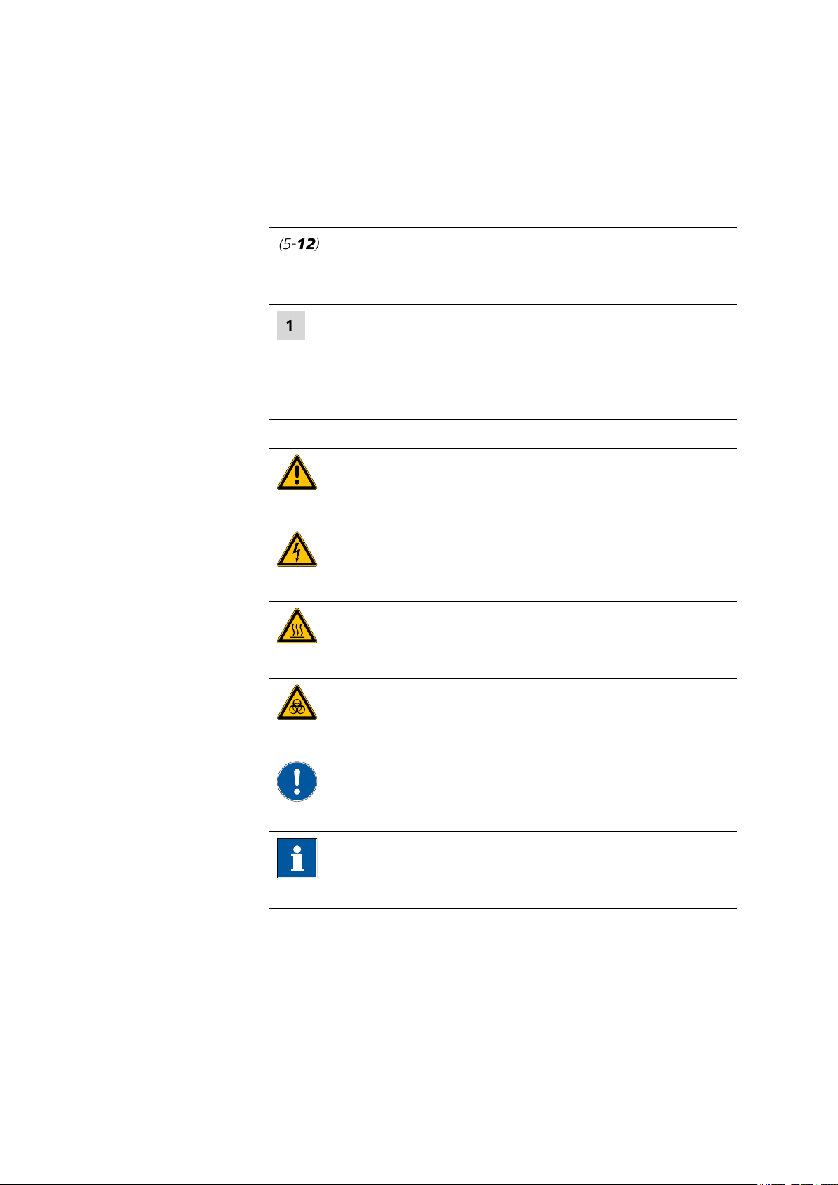
The following symbols and formatting may appear in this documentation:
Method Dialog text, parameter in the software
File ▶ New Menu or menu item
[Next] Button or key
1 Introduction
Cross-reference to figure legend
The first number refers to the figure number, the second to the instrument part in the figure.
Instruction step
Carry out these steps in the sequence shown.
WARNING
This symbol draws attention to a possible life-threatening hazard or risk of injury.
WARNING
This symbol draws attention to a possible hazard due
to electrical current.
WARNING
This symbol draws attention to a possible hazard due
to heat or hot instrument parts.
WARNING
This symbol draws attention to a possible biological
hazard.
CAUTION
This symbol draws attention to possible damage to
instruments or instrument parts.
NOTE
This symbol highlights additional information and
tips.
945 Professional Detector Vario – Conductivity & Amperometry (2.945.0030)
■■■■■■■■
5
Page 14

2.1 Front
2
3
1
4 5
6
7
8
2 Overview of the instrument
2.1 Front
■■■■■■■■■■■■■■■■■■■■■■
Figure 1 Front – Front cover attached
Power LED
1
Amperometric detector standby indicator.
Conductivity detector
3
Permanently installed.
Front cover
5
For the amperometric detector.
Coupling
7
For connecting the detector outlet capillary
of the conductivity detector. Labeled Cond.
Eluent out.
Amperometric detector
2
Permanently installed.
Power LED
4
Instrument standby indicator.
Knurled screw
6
For removing the front cover.
Detector inlet capillary
8
Of the conductivity detector. Permanently
mounted.
■■■■■■■■
6
945 Professional Detector Vario – Conductivity & Amperometry (2.945.0030)
Page 15
■■■■■■■■■■■■■■■■■■■■■■
1
2
3
4
5
6
7
8 109
2 Overview of the instrument
Figure 2 Front – Front cover removed
AE connection socket
1
For connecting the auxiliary electrode.
Cell holder
3
With chip for the automatic detection of the
measuring cell.
RE connection socket
5
For connecting the reference electrode.
Tray
7
Thread
9
For the knurled screw used for fastening the
front cover.
Power LED
2
Amperometric detector standby indicator.
WE connection socket
4
For connecting the working electrode.
Coupling
6
For connecting a connection capillary to the
measuring cell. Labeled Eluent to cell.
Drain nozzle
8
For draining liquid from the tray. Plugged
with a stopper.
Coupling
10
For connecting the detector inlet capillary.
Labeled Eluent in.
945 Professional Detector Vario – Conductivity & Amperometry (2.945.0030)
■■■■■■■■
7
Page 16
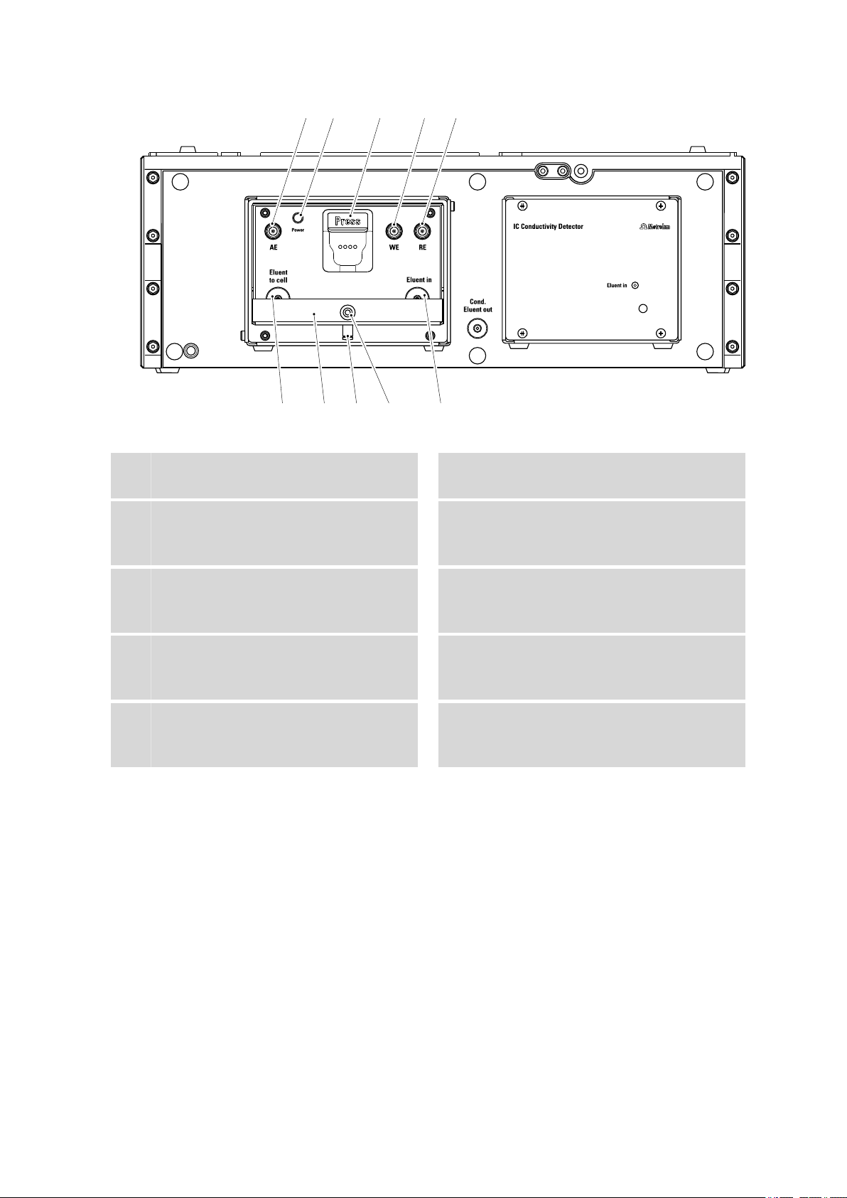
2.2 Rear
1
2
3
4
5
6
7
8 9
10
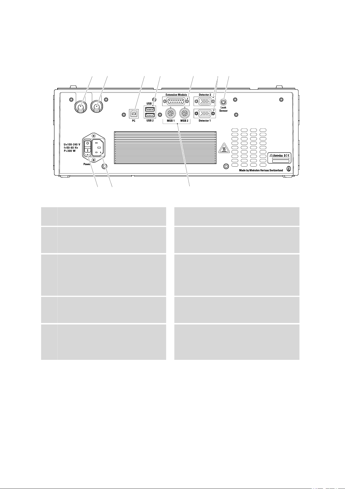
2.2 Rear
■■■■■■■■■■■■■■■■■■■■■■
Figure 3 Rear
Cable feed-through
1
Output for the detector cable.
PC connection socket
3
For connecting the instrument to the computer with the USB cable (6.2151.020).
Extension Module connection socket
5
For connecting a 942 Extension Module
Vario or an 891 Professional Analog Out.
Labeled Extension Module.
Leak sensor connection socket
7
For connecting the leak sensor connection
cable, labeled Leak Sensor.
Power socket
9
For connecting the power supply cable
(6.2122.0x0).
Cable feed-through
2
Output for the detector cable.
USB connection sockets
4
Two USB connection sockets, labeled USB 1
and USB 2.
Detector connection sockets
6
For the connection of the installed detector,
labeled Detector 1 and Detector 2. The
detector connection sockets which are not
used must be covered with a lid.
Power switch
8
For switching the instrument on and off.
MSB connection sockets
10
Two MSB connection sockets (labeled MSB 1
and MSB 2) for connecting MSB devices.
(MSB = Metrohm Serial Bus)
■■■■■■■■
8
945 Professional Detector Vario – Conductivity & Amperometry (2.945.0030)
Page 17

■■■■■■■■■■■■■■■■■■■■■■
3 Installation
3.1 Base tray and bottle holder
3.1.1 Basic information on base tray and bottle holder
The base tray (6.2061.110) and bottle holder (6.2061.100) protect IC
instruments from dust, dirt and leaking fluids. The supply bottles for eluent
and auxiliary solutions can be positioned neatly on the bottle holder.
In a complex IC system, several different instruments may be used, such as
an analyzer, an extension module and a detector. These instruments can
be set up in one or more stacks. We recommend that a base tray and bottle holder be mounted for each stack of IC instruments.
The bottle holder and base tray must be removed or set up every time one
of the following instruments is to be mounted on or under a 940 Professional IC Vario:
3 Installation
■ One or more 942 Extension Module Vario.
■ One 944 Professional UV/VIS Detector Vario.
■ One 945 Professional Detector Vario.
■ Or another instrument with the same-sized footprint.
3.1.2 Mounting base tray and bottle holder (optional)
The base tray and bottle holder come fully assembled on a new ion chromatograph. If you wished to install an extension module on the ion chromatograph, you would have to remove the bottle holder and put it back
on top of the topmost instrument. If you wished to install an extension
module below the ion chromatograph, you would have to remove the
base tray and set it under the lowest instrument.
3.1.2.1
Removing/mounting the base tray
The base tray must be removed if you want to install another instrument
under the IC instrument.
CAUTION
Do not allow capillaries or leak sensor cables to be pinched!
Pinches in the leak sensor cable or the capillaries fed through the guide
ducts between the base tray and the instrument may lead to malfunctions.
Unplug the leak sensor cable. Remove all of the capillaries from the
capillary ducts.
945 Professional Detector Vario – Conductivity & Amperometry (2.945.0030)
■■■■■■■■
9
Page 18

3.1 Base tray and bottle holder
1
2
3
■■■■■■■■■■■■■■■■■■■■■■
Removing the base tray
Before you can remove the base tray, the following preconditions must be
met:
■ The instrument is switched off.
■ The bottle holder is cleared.
■ All of the cable connections on the rear have been disconnected.
■ The capillaries are removed from the guide ducts between the instru-
ment and the base tray.
■ There are no loose parts in the instrument.
To remove the base tray, you need a 3 mm hex key (6.2621.100).
Tilt the instrument sideways and lay it down flat.
1
Loosen the four cylinder screws with the 3 mm hex key and remove
2
them and their washers.
Remove the base tray.
3
The base tray must always be mounted under the lowermost instrument
of the stack.
Mounting the base tray
Before you can mount the base tray, the following preconditions must be
met:
■ The instrument is switched off.
■ The bottle holder is cleared.
■ All of the cable connections on the rear have been disconnected.
■ There are no loose parts in the instrument.
■■■■■■■■
10
945 Professional Detector Vario – Conductivity & Amperometry (2.945.0030)
Page 19

■■■■■■■■■■■■■■■■■■■■■■
3 Installation
■ The instrument is lying on its side, and the bottom surface is visible.
To mount the base tray, you need a 3 mm hex key (6.2621.100).
Place the base tray in such a way that the openings in the base tray
1
match exactly the screw threads in the bottom of the instrument.
Slide the washers onto the cylinder screws, insert the screws and
2
tighten them with the 3 mm hex key.
Set the instrument back up on the base tray.
3
3.1.2.2
Stack other instruments in the required order. Mount the bottle holder
(6.2061.100) onto the topmost instrument on the stack (see "Mounting
the bottle holder", page 13).
Removing/mounting the bottle holder
The bottle holder must be removed if you want to install another instrument onto the IC instrument.
Removing the bottle holder
Before you can remove the bottle holder, the following preconditions
must be met:
■ The instrument is switched off.
■ The bottle holder is cleared.
■ Drainage tubing is disconnected from the drainage tubing connection
of the bottle holder.
■ The capillaries are removed from the guide ducts between the instru-
ment and the bottle holder.
To remove the bottle holder, you need a 3 mm hex key (6.2621.100).
945 Professional Detector Vario – Conductivity & Amperometry (2.945.0030)
■■■■■■■■
11
Page 20

3.1 Base tray and bottle holder
1
2 3
■■■■■■■■■■■■■■■■■■■■■■
Remove the two covering stoppers.
1
Loosen the two cylinder screws with the 3 mm hex key and remove
2
them.
Remove the bottle holder.
3
Stack other instruments in the required order. Mount the bottle holder
(6.2061.100) onto the topmost instrument on the stack.
■■■■■■■■
12
945 Professional Detector Vario – Conductivity & Amperometry (2.945.0030)
Page 21

■■■■■■■■■■■■■■■■■■■■■■
1
2 3
3 Installation
Mounting the bottle holder
Before you can mount the bottle holder, the following preconditions must
be met:
■ The instrument is switched off.
To mount the bottle holder, you need a 3 mm hex key (6.2621.100).
Place the bottle holder onto the topmost instrument in such a way
1
that the openings in the bottle holder exactly match the screw
threads on the top surface of the instrument.
Insert the two cylinder screws and tighten them with the 3 mm hex
2
key.
Insert both covering stoppers.
3
After attaching the bottle holder, all connections that were undone at the
beginning of the process must be reconnected.
Restoring the loosened connections
Plug in all necessary USB cables.
1
Plug in all necessary MSB cables.
2
Plug in the power supply cable.
3
Mount the drainage tubing again (see manual of the IC instrument).
4
945 Professional Detector Vario – Conductivity & Amperometry (2.945.0030)
■■■■■■■■
13
Page 22

3.2 Connecting the instrument to a computer
■■■■■■■■■■■■■■■■■■■■■■
A longer section of silicone tubing (6.1816.020) may have to be cut
to size and mounted (see also the manual for the IC instrument).
If one of the instruments in the stack is equipped with a leak sensor
5
connection socket, connect the leak sensor (see manual of the IC
instrument).
Restore any capillary connections that may have been removed.
6
3.2 Connecting the instrument to a computer
NOTE
The instrument must be switched off when being connected to a computer.
Accessories
For this step you need the following accessories:
■ USB connecting cable (6.2151.020)
Connecting the USB cable
Insert the USB cable into the computer connection socket on the rear
1
of the instrument labeled PC.
Insert the other end into a USB port on the computer.
2
3.3 Connecting the instrument to the power supply
WARNING
The power supply unit must not get wet. Protect it from liquids.
The power supply cable is three-core and provided with a plug with
grounding. If another plug has to be mounted, the yellow/green conductor (IEC standard) must be connected to the protective ground (protection
class I).
Accessories
■■■■■■■■
14
For this step you need the following accessories:
■ For Switzerland, …: Power supply cable with IEC 60320 line socket,
type C13, with SEV 1011 plug, type 12 (6.2122.020), 1.5 m
945 Professional Detector Vario – Conductivity & Amperometry (2.945.0030)
Page 23

■■■■■■■■■■■■■■■■■■■■■■
3 Installation
■ For Germany, …: Power supply cable with IEC 60320 line socket, type
C13, with CEE 7 plug, type VII (6.2122.040), 1.5 m
■ For the USA, …: Power supply cable with IEC 60320 line socket, type
C13, with NEMA 5-15 plug, type 498 (6.2122.070), 1.5 m
Connecting the power supply cable
1
Inserting the power supply cable
■ Insert the power supply cable into the instrument's power socket.
■ Connect the power supply cable to the power supply.
2
Switching on the instrument
Switch on the instrument using the power switch.
After being switched on, the LED on the front of the instrument
flashes. The instrument conducts a system test and establishes a connection to the software. Once the system test is complete and the
connection to the software has been established, the LED lights up
continuously.
3.4 Conductivity detector
3.4.1 Connecting the detector capillaries
Accessories
For this step you need the following accessories:
■ PEEK capillary (6.1831.030)
■ Pressure screw (6.2744.010)
Connecting the detector outlet capillary
■ Use a pressure screw (6.2744.010) to screw one end of the PEEK
1
capillary (6.1831.030) firmly to the coupling Cond. Eluent out.
■ Fasten the other end of the PEEK capillary (6.1381.030) to the
2
waste collector (6.5336.000) or guide it into a sufficiently large
waste container and fasten it there.
OR if the application requires a subsequent amperometric detection:
■ Connect the other end of the PEEK capillary (6.1381.030) to the
Eluent in connector on the amperometric detector.
945 Professional Detector Vario – Conductivity & Amperometry (2.945.0030)
■■■■■■■■
15
Page 24

3.4 Conductivity detector
■■■■■■■■■■■■■■■■■■■■■■
NOTE
The detector outlet capillary must be free of blockages in order to
generate sufficient backpressure (the measuring cell is tested to 5
MPa = 50 bar backpressure).
Connecting the detector inlet capillary
The detector inlet capillary is connected differently depending on the
equipment of the IC instruments:
■ For instruments without suppression, directly to the separation column
(see "Connecting the detector inlet capillary to the separation column", page 16).
■ For instruments with chemical suppression, to the suppressor (see
"Connecting the detector inlet capillary to the suppressor", page
17).
■ For instruments with sequential suppression, to the MCS (see "Con-
necting the detector inlet capillary to the MCS", page 17).
NOTE
In order to prevent unnecessary peak widening after separation, the
connection between the outlet of the separation column and the inlet
to the detector should be kept as short as possible.
Connecting the detector inlet capillary to the separation
column
1
Connecting the detector inlet
■ Fasten the detector inlet capillary (4-1) using a short PEEK pres-
sure screw (6.2744.070) (4-2) directly to the outlet of the column
(4-3).
■■■■■■■■
16
945 Professional Detector Vario – Conductivity & Amperometry (2.945.0030)
Page 25

■■■■■■■■■■■■■■■■■■■■■■
1
2
3
1 2
3
3 Installation
Figure 4 Connection detector–separation column
Detector inlet capillary
1
Separation column
3
PEEK pressure screw, short
2
(6.2744.070)
Connecting the detector inlet capillary to the suppressor
1
Connecting the detector inlet
■ Connect the detector inlet capillary (5-1) and the capillary of the
suppressor (5-2) labeled out to each other using a coupling
(6.2744.040) (5-3) and two short PEEK pressure screws
(6.2744.070) (5-4).
Figure 5 Connection detector–suppressor
Detector inlet capillary
1
Coupling (6.2744.040)
3
945 Professional Detector Vario – Conductivity & Amperometry (2.945.0030)
Suppressor outlet capillary
2
Labeled out.
PEEK pressure screws, short
4
(6.2744.070)
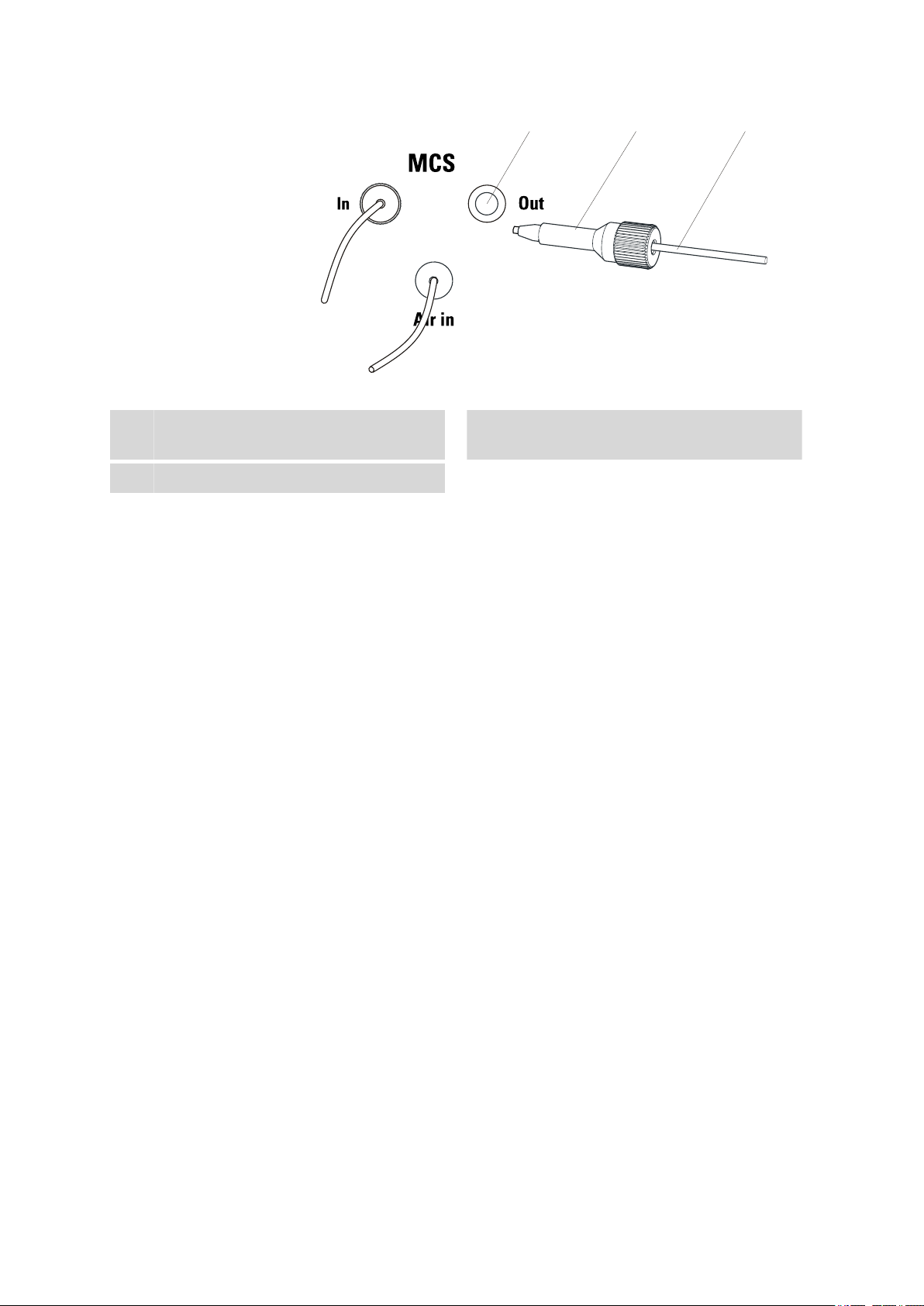
Connecting the detector inlet capillary to the MCS
1
Connecting the detector inlet
■ Fasten the detector inlet capillary (6-1) with one long PEEK pres-
sure screw (6.2744.090) (6-2) to the outlet of the MCS (6-3).
■■■■■■■■
17
Page 26
3.5 Amperometric detector
3 2
1
■■■■■■■■■■■■■■■■■■■■■■
Figure 6 Connection detector–MCS
Detector inlet capillary
1
MCS outlet
3
3.5 Amperometric detector
The following tasks are part of the installation of the amperometric detector:
■ Inserting the working electrode and the reference electrode into the
measuring cell (see the measuring cell manual).
■ Connecting the capillaries to the preheating capillary or directly to the
measuring cell.
■ Inserting the measuring cell into the detector.
■ Deaerating the measuring cell.
■ Connecting the electrode cables.
■ Attaching the front cover.
Because not only the capillaries but also the electrode cables must be
tested prior to their first use, none of these installation tasks are carried
out until the time of the first start-up.
PEEK pressure screw, long
2
(6.2744.090)
■■■■■■■■
18
945 Professional Detector Vario – Conductivity & Amperometry (2.945.0030)
Page 27

■■■■■■■■■■■■■■■■■■■■■■
4 Start-up
The 945 Professional Detector Vario – Conductivity & Amperometry is put
into operation together with the IC system. Additional information can be
found in the Start-up chapter in the manual for the IC instrument.
The following tests and installation tasks must be performed during the
first start-up of the IC instrument with the 945 Professional Detector Vario
– Conductivity & Amperometry.
4.1 Instrument test with dummy cell
When you are putting the 945 Professional Detector Vario – Conductivity
& Amperometry into operation for the first time, or when problems occur
which may be caused by signal recording or signal transfer, we recommend testing the electronics and the connection to the PC using the
dummy cell (6.2813.040).
4 Start-up
Proceed as follows:
Testing with the dummy cell
Prerequisites:
■ In order to achieve accurate results, we recommend that the front
cover be closed during the instrument test with the dummy cell. Since
the space under the front cover is rather limited, we further recommend removing the measuring cell from the cell holder for the instrument test with the dummy cell.
For the instrument test you require:
■ The dummy cell (6.2813.040)
■ The three electrode connection cables (6.2165.000)
1
Connecting the electrode connection cables to the dummy
cell
■ Plug the angled plug of the working electrode connection cable
(labeled WE) into the WE socket.
■ Plug the angled plug of the reference electrode connection cable
(labeled RE) into the RE socket.
■ Plug the angled plug of the auxiliary electrode connection cable
(labeled AE) into the AE socket.
945 Professional Detector Vario – Conductivity & Amperometry (2.945.0030)
■■■■■■■■
19
Page 28

4.1 Instrument test with dummy cell
■■■■■■■■■■■■■■■■■■■■■■
2
Connecting the electrode connection cables to the detector
(unless they are already connected)
■ Plug the straight plug of the working electrode connection cable
(red sleeve) into the WE socket of the detector.
■ Plug the straight plug of the reference electrode connection cable
(black sleeve) into the RE socket of the detector.
■ Plug the straight plug of the auxiliary electrode connection cable
(blue sleeve) into the AE socket of the detector.
3
Inserting the dummy cell
■ Place the dummy cell into the tray of the detector.
■ Attach the front cover.
NOTE
The metal parts of the cable plugs must not touch the front cover.
4
Adjusting settings in MagIC Net
In the Method program part, create a new method for the instrument test with the dummy cell.
■ Select the detector and add it as a new device.
■ Select the DC mode.
■ Set the following parameters for the DC mode:
– DC potential: 0.8 V
– Range: Auto
– Damping: off
■ Add an analysis for the detector channel Current.
■ Add the entry Current ▶ Start data acquisition in the Time
program subwindow.
■ Save the method.
In the Workplace program part:
■ Load the method.
■ In the Watch window, display the Current channel with at least
three decimal places.
5
Carrying out the test
In the Manual program part:
■■■■■■■■
20
945 Professional Detector Vario – Conductivity & Amperometry (2.945.0030)
Page 29

■■■■■■■■■■■■■■■■■■■■■■
■ On the tab of the detector, switch on the dummy cell with
[Apply].
After no more than one minute, the detector signal should level
off at 2.667 nA ± 7%. Noise should not exceed 0.005 nA.
■ Switch the dummy cell off with [Cell Off].
With the dummy cell switched off and the detector hardware still
running, the signal should drop below an absolute value of 1 nA,
and noise should be limited to the third decimal place.
Exactly even signals may indicate that new detector data is not
correctly transmitted.
6
Removing the dummy cell
■ Pull out the electrode connection cables from the connectors AE,
WE and RE of the dummy cell.
■ Remove the dummy cell from the tray.
4 Start-up
The dummy cell incorporates a resistor (300 M
connected in parallel. If, in DC mode, a potential of 0.8 V is applied, then
a current of 2.667 nA (± 7%) is measured in the dummy cell. The capacitor simulates a well-working measuring cell.
4.2 Testing the leak sensor
The leak sensor should not respond during the start-up. If the leak sensor
nevertheless does respond during the start-up, you will find information
for eliminating the problem in Chapter (see Chapter 6.1, page 34).
To check whether the leak sensor is functioning, proceed as follows:
Testing the leak sensor
Hold a cloth moistened with eluent or tap water on the two contacts
1
of the leak sensor .
The leak sensor of the detector responds.
If the leak sensor does not respond, please request Metrohm Service.
Ω) and a capacitor (100 nF)
945 Professional Detector Vario – Conductivity & Amperometry (2.945.0030)
■■■■■■■■
21
Page 30

4.3 Testing the preheating capillary
4.3 Testing the preheating capillary
The amperometric detector is equipped with a preheating capillary in its
interior to ensure that the eluent flows through the measuring cell at a
constant temperature. The preheating capillary need not, however, always
be connected. If the ambient conditions are optimal, then the measuring
results can be sufficiently accurate, even without the use of the preheating
capillary.
CAUTION
The preheating capillary may not be used when working with highly
flammable liquids.
The preheating capillary must be free of both leaks and blockages.
To check whether the preheating capillary is free of both leaks and blockages, proceed as follows:
■■■■■■■■■■■■■■■■■■■■■■
Testing the preheating capillary
1
Connecting the detector inlet capillary
Use a pressure screw (6.2744.014) to fasten the detector inlet capillary to the Eluent in connector on the detector.
2
Adjusting the settings in MagIC Net
■ In the program part Manual of MagIC Net, set the maximum
pressure of the high-pressure pump to 5 MPa.
■ Set the flow rate to 0.1 mL/min.
■ Start the high-pressure pump.
3
Observe the Eluent to cell connector
After a while, liquid must emerge from the Eluent to cell connector
(wipe up fluid with paper towel).
If no liquid emerges at the Eluent to cell connector, then the preheating capillary is likely to be blocked. To eliminate the problem, see
Chapter Preheating capillary maintenance, page 32.
4
Observe the pump pressure
Observe the pump pressure display in the program part Manual of
MagIC Net.
■■■■■■■■
22
945 Professional Detector Vario – Conductivity & Amperometry (2.945.0030)
Page 31

■■■■■■■■■■■■■■■■■■■■■■
A constant pressure should establish itself after a while.
4.4 Testing the detector outlet capillary
The detector outlet capillary must be of a certain length in order to be
able to generate sufficient backpressure. The required length is dependent
on the flow that has been set. The table 1 shows the recommended
lengths, as determined by the set flow rate.
Table 1 Recommended lengths for the detector outlet capillary
Flow rate Capillary length (⌀0.25 mm)
2.0 mL/min 0.5 - 1.5 m
0.5 - 1.0 mL/min 1.0 - 2.5 m
0.25 mL/min 3 m
To check whether the detector outlet capillary is free of blockages, proceed as follows:
4 Start-up
Testing the detector outlet capillary
Prerequisites:
■ The detector inlet capillary is connected to the Eluent in connector.
■ The high-pressure pump runs with a flow rate of 0.1 mL/min.
1
Connecting the detector outlet capillary
Use a pressure screw (6.2744.014) to fasten the detector outlet
capillary to the Eluent to cell connector.
2
Adjusting the settings in MagIC Net
In the program part Manual of MagIC Net, increase the flow rate to
1.0 mL/min and wait until the pressure has stabilized.
3
Observe the end of the detector outlet capillary
After a while, liquid must emerge from the end of the detector outlet
capillary.
If no liquid emerges at the end of the detector outlet capillary, then
the detector outlet capillary is blocked and must either be cut back
once again or replaced.
945 Professional Detector Vario – Conductivity & Amperometry (2.945.0030)
■■■■■■■■
23
Page 32

4.5 Testing the measuring cell
■■■■■■■■■■■■■■■■■■■■■■
4
Loosening the detector outlet capillary
Loosen the detector outlet capillary from the Eluent to cell connector. Wipe up emerging liquid with a cloth.
5
Observe the pump pressure
Observe the pump pressure display in the program part Manual of
MagIC Net.
The drop in pressure should range from 0.1 MPa to a maximum of
0.3 MPa.
If the pressure differential is greater, then the detector outlet capillary
must be cut back once again or replaced.
6
Finish the test
■ In the program part Manual of MagIC Net, stop the high-pres-
sure pump.
■ Remove the detector outlet capillary from the Eluent to cell con-
nector.
4.5 Testing the measuring cell
To test the measuring cell, proceed as follows:
Testing the measuring cell
Prerequisites:
■ The measuring cell is completely assembled (see measuring cell man-
ual).
■ The working electrode and the reference electrode are inserted (see
measuring cell manual).
1
Connecting the measuring cell
■ Connecting the measuring cell inlet:
– When the preheating capillary is used: Use a pressure
screw (6.2744.014) to fasten a piece of the PEEK capillary
(6.1831.010) to the Eluent to cell connector on the
detector.
Use a pressure screw (6.2744.014) to fasten the other end
to the In connector of the measuring cell.
– If the preheating capillary is not used: Use a pressure screw
(6.2744.014) to fasten the detector inlet capillary directly to
the In connector on the measuring cell.
■■■■■■■■
24
945 Professional Detector Vario – Conductivity & Amperometry (2.945.0030)
Page 33
■■■■■■■■■■■■■■■■■■■■■■
■ Connecting the measuring cell outlet:
Use a pressure screw (6.2744.014) to fasten the tested detector
outlet capillary to the Out connector on the measuring cell (see
"Testing the detector outlet capillary", page 23).
2
Inserting the measuring cell
Insert the chip of the measuring cell into the cell holder so that you
can hear it locking in.
4 Start-up
NOTE
Do not move the measuring cell for at least 5 seconds after having
inserted it.
During this time, data is read from the chip of the measuring cell
and written into the database. This process must not be interrupted, because otherwise the data may be transferred incorrectly or
incompletely.
3
Testing at low flow
■ In the program part Manual of MagIC Net, set the flow rate of
the high-pressure pump to 0.2 mL/min and start the high-pressure
pump.
945 Professional Detector Vario – Conductivity & Amperometry (2.945.0030)
■■■■■■■■
25
Page 34

4.6 Deaerating the measuring cell
■■■■■■■■■■■■■■■■■■■■■■
■ Watch the detector outlet capillary: Liquid must emerge from the
end of the detector outlet capillary.
If no liquid emerges from the end of the detector outlet capillary:
– Detach the capillary from the Out connection on the mea-
suring cell and check whether the end has been pinched by
the pressure screw.
– Shorten the capillary and fasten once again to the Out con-
nector on the measuring cell.
■ Observe the measuring cell: No liquid should emerge from the
body of the measuring cell.
If the measuring cell is leaking:
– Remove the measuring cell from the measuring cell holder.
– Remove all capillaries and cables.
– Check whether the pressure screw of the working electrode
is properly connected and retighten it.
– Restore the capillary connections.
– Reinsert the electrode cables.
– Reinsert the measuring cell.
– Repeat the test.
4
Testing at normal flow
■ In the program part Manual of MagIC Net, raise the flow rate of
the high-pressure pump to 1.0 mL/min.
■ Observe the measuring cell: No liquid should emerge from the
body of the measuring cell.
4.6 Deaerating the measuring cell
The cell must be deaerated in order to ensure that it contains no air bubbles.
The measuring cell must be deaerated after the installation and after each
subsequent opening of the cell.
Proceed as follows:
Deaerating the measuring cell
Prerequisites:
■ The high-pressure pump is switched on and pumps the eluent through
the IC system to the measuring cell.
■ The measuring cell is switched off.
1
Deaerating the reference electrode chamber
■ Unscrew the nut on the RE connector and remove it.
■■■■■■■■
26
945 Professional Detector Vario – Conductivity & Amperometry (2.945.0030)
Page 35

■■■■■■■■■■■■■■■■■■■■■■
■ Lift out the reference electrode.
■ Wait until the reference electrode chamber has filled with eluent.
■ Reinsert the reference electrode. Wipe up any emerging eluent
with a cloth.
■ Screw the nut on the reference electrode connector back on
tightly.
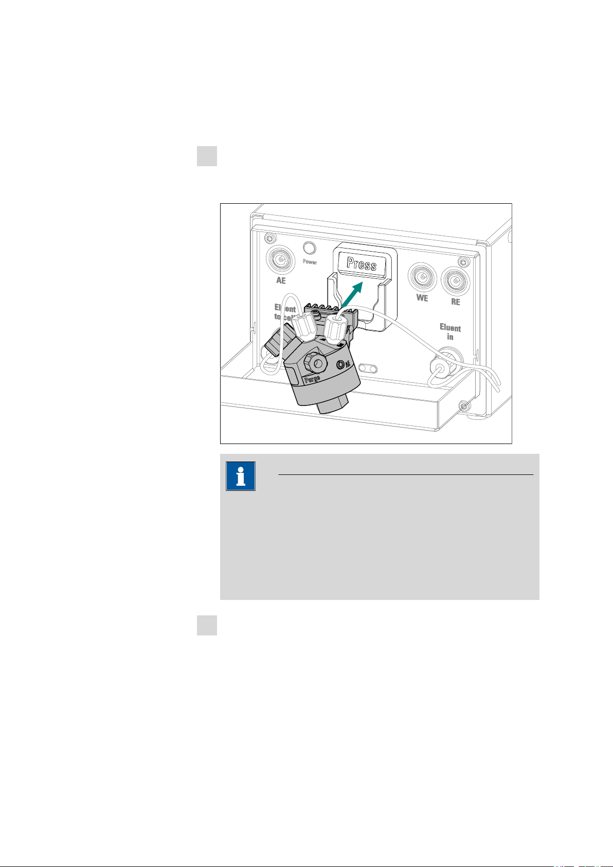
2
Removing the purge stopper
Remove the stopper from the Purge connector.
4 Start-up
3
Deaerating the measuring cell
Observe the eluent that emerges through the deaeration opening.
Wipe up liquid with a cloth.
Once no more air bubbles are visible, screw the stopper back on the
Purge connector and tighten it by hand.
Switch off the high-pressure pump in MagIC Net.
4
4.7 Connecting the electrode cables
CAUTION
The electrode cables may not be plugged or unplugged unless the measuring cell is switched off in the software.
NOTE
The sockets and the plugs of the cables must be clean and dry.
945 Professional Detector Vario – Conductivity & Amperometry (2.945.0030)
■■■■■■■■
27
Page 36

4.7 Connecting the electrode cables
■■■■■■■■■■■■■■■■■■■■■■
Connecting the electrode cables to the detector
Prerequisites:
■ The measuring cell is switched off.
Plug the straight plug of the working electrode cable (red sleeve) into
1
the WE socket of the detector.
Plug the straight plug of the reference electrode cable (black sleeve)
2
into the RE socket of the detector.
Plug the straight plug of the auxiliary electrode cable (blue sleeve)
3
into the AE socket of the detector.
Connecting the electrode cables to the measuring cell
Prerequisites:
■ The working electrode and the reference electrode are inserted into
the measuring cell.
Plug the angled plug of the working electrode cable (labeled WE)
1
into the working electrode socket.
Plug the angled plug of the reference electrode cable (labeled RE)
2
into the reference electrode socket.
Plug the angled plug of the auxiliary electrode cable (labeled AE) into
3
the socket (labeled AE).
■■■■■■■■
28
945 Professional Detector Vario – Conductivity & Amperometry (2.945.0030)
Page 37

■■■■■■■■■■■■■■■■■■■■■■
4.8 Attaching the front cover
In order to obtain good measuring results, we recommend that the front
cover be put back in place.
When you are attaching the front cover, observe the following:
■ Do not pinch any capillaries!
Guide the capillaries through the capillary feed-throughs .
■ Do not pinch any cables!
4 Start-up
945 Professional Detector Vario – Conductivity & Amperometry (2.945.0030)
■■■■■■■■
29
Page 38

5.1 General notes
5 Operation and maintenance
5.1 General notes
5.1.1 Care
WARNING
Untrained personnel may not open the instrument's housing.
The instrument requires appropriate care. Excess contamination of the
instrument may result in malfunctions and a reduction in the service life of
the sturdy mechanical and electronic components.
CAUTION
■■■■■■■■■■■■■■■■■■■■■■
Even though design measures ensure that this will largely be prevented,
the detector should be switched off without delay in the event that
aggressive media have found their way into the interior of the detector.
This is the only way to prevent extreme damage to the instrument electronics. In such cases, Metrohm Service must be informed.
Spilled chemicals and solvents should be removed immediately. In particular, the plug connections (particularly the power plug) should be protected
from contamination.
Do not use scouring agents for cleaning the tray.
5.1.2 Maintenance by Metrohm Service
Maintenance of the instrument is best carried out as part of annual service, which is performed by specialist personnel from Metrohm. A shorter
maintenance interval is recommended if you frequently work with caustic
and corrosive chemicals. Metrohm Service provides professional technical
consultation at all times for the maintenance and servicing of all Metrohm
instruments.
5.1.3 Operation
■■■■■■■■
30
CAUTION
In order to avoid disruptive temperature influences, the entire system
must be protected from direct sunlight.
945 Professional Detector Vario – Conductivity & Amperometry (2.945.0030)
Page 39

■■■■■■■■■■■■■■■■■■■■■■
5.1.4 Shutting down
If the instrument is shut down for a longer period of time, the entire IC
system must be rinsed as follows to rid it of salts in order to prevent eluent salts from forming crystals which may cause subsequent damage.
■ Rinse all capillaries and the Dosino (if present) with methanol/ultrapure
water (1:4).
■ Rinse all pump tubings of the peristaltic pump with ultrapure water.
5.2 Conductivity detector
5.2.1 Maintenance
CAUTION
The conductivity detector must not be opened!
5 Operation and maintenance
WARNING
When rinsing the detector without column, the pressure must not
exceed 5 MPa.
In order to ensure this, set the maximum pressure of the high-pressure
pump to 5 MPa in MagIC Net.
5.2.2 Remedying blockage
The conductivity detector can become blocked if the ends of the detector
inlet capillary or the detector outlet capillary are pressed together too
tightly.
If this is the case, detach and shorten the detector inlet capillary or the
detector outlet capillary by a few millimeters.
If the conductivity detector is still blocked even if the capillary ends are
free then it can be rinsed in the direction opposite the normal flow direction. Proceed as follows:
Detach the detector inlet capillary or the detector outlet capillary
1
from the system.
Connect the detector outlet capillary directly to the outlet of the
2
high-pressure pump.
945 Professional Detector Vario – Conductivity & Amperometry (2.945.0030)
■■■■■■■■
31
Page 40

5.3 Amperometric detector
In MagIC Net, set the maximum pressure of the high-pressure pump
3
to 5 MPa.
Rinse the detector thoroughly with eluent.
4
5.3 Amperometric detector
5.3.1 Maintenance
WARNING
When rinsing the detector without column, the pressure must not
exceed 5 MPa.
In order to ensure this, set the maximum pressure of the high pressure
pump to 5 MPa in MagIC Net.
■■■■■■■■■■■■■■■■■■■■■■
5.3.2 Preheating capillary maintenance
The preheating capillary can become blocked, e.g. if the IC system has
inadvertently been run dry.
To dissolve this blockage, proceed as follows:
Rinsing the preheating capillary
1
Removing the separation column
Remove the separation column from the IC system and replace with
a coupling (6.2744.040).
2
Adjusting the settings in MagIC Net
In MagIC Net, adjust the following settings:
■ Maximum pressure of the high-pressure pump: 5 MPa
■ Flow rate: < 0.1 mL/min
Rinse the system with the same eluent as before the blockage or
3
with ultrapure water.
■■■■■■■■
32
The eluent requires sufficient time to trickle through and dissolve the
crystals.
Do not increase the flow rate until the pressure has stabilized.
4
945 Professional Detector Vario – Conductivity & Amperometry (2.945.0030)
Page 41

■■■■■■■■■■■■■■■■■■■■■■
If the preheating capillary remains blocked, then you can attempt to rinse
the capillary in the opposite direction. To accomplish this, connect the
detector inlet capillary to the connector Eluent to cell and repeat the
procedure (see "Rinsing the preheating capillary", page 32).
If the blockage can also not be dissolved by rinsing in the opposite direction, then the preheating capillary must be replaced by a Metrohm Service
employee.
5 Operation and maintenance
5.4 Quality management and qualification with Metrohm
Quality management
Metrohm offers you comprehensive support in implementing quality management measures for instruments and software.
Qualification
Please contact your local Metrohm representative for support in qualification of instruments and software. The Installation Qualification (IQ)
and Operational Qualification (OQ) are offered by Metrohm representatives as a service. They are carried out by trained employees using standardized qualification documents and in accordance with the currently
applicable requirements of the regulated industry.
Maintenance
The electronic and mechanical functional groups of Metrohm instruments
can and should be checked by specialist personnel from Metrohm as part
of a regular preventive maintenance schedule. Please ask your local
Metrohm representative regarding the precise terms and conditions
involved in concluding a corresponding maintenance agreement.
For detailed information on this topic, please visit www.metrohm.com.
945 Professional Detector Vario – Conductivity & Amperometry (2.945.0030)
■■■■■■■■
33
Page 42

6.1 Problems with the hardware
6 Troubleshooting
6.1 Problems with the hardware
Problem Cause Remedy
■■■■■■■■■■■■■■■■■■■■■■
Leak sensor
responds.
Leaking capillary connection.
Find any leaking capillary connections and seal
them.
Measuring cell leaking. Screw apart the measuring cell and then reas-
semble it.
The amperometric
detector is not rec-
IC system – No connection. ■ Check the cable connection.
■ Switch the IC instrument off and then on
ognized in the software.
6.2 Problems with the baseline
Problem
Pulsing baseline. High-pressure pump – Con-
Cause Remedy
Clean valves (see Chapter Operation and
taminated valves.
maintenance in the manual for the IC instru-
ment).
High-pressure pump –
Defective piston seal.
Replace the piston seals (see Chapter Operation and maintenance in the manual for the IC
instrument).
again after 15 seconds.
■■■■■■■■
34
High-pressure pump –
Quality of the pump is not
sufficient for the selected
sensitivity.
Measuring cell – Air bubble
in the measuring cell.
IC system – temperature
fluctuations.
945 Professional Detector Vario – Conductivity & Amperometry (2.945.0030)
■ Use a pulsation absorber.
■ Use a higher-performance high-pressure
pump.
■ Reduce the sensitivity.
■ Deaerate the measuring cell.
■ Degas the eluent continuously.
■ Switch on the column thermostat or the
column oven.
■ Amperometric detector – Connect the pre-
heating capillary .
■ Amperometric detector – Attach and close
the front cover (see Chapter 4.8, page 29).
Page 43

■■■■■■■■■■■■■■■■■■■■■■
Problem Cause Remedy
6 Troubleshooting
Smooth baseline (no
noise).
Measuring cell – Working
electrode contaminated.
Measuring cell – Measuring cell leaking.
IC system – Eluent contaminated.
Communications problem
between the amperometric
detector and MagIC Net.
All of the data lies outside
of the measuring range.
Short-circuit bridge
between the electrodes.
Clean the working electrode (see the leaflet for
the working electrode).
Check the capillary connections on the measuring cell.
Prepare a new eluent.
■ Check whether the electrode cables are
properly connected.
■ Check the electrode cable with dummy cell
(see Chapter 4.1, page 19).
■ Switch off the instrument, close and restart
MagIC Net, switch the instrument back on.
■ Adjust the measuring range.
■ Deaerate the measuring cell (see "Deaerat-
ing the measuring cell", page 26).
■ Examine the working electrode for promi-
nent deposits.
■ Polish the working electrode (see the leaflet
for the working electrode).
■ Replace the working electrode.
■ Clean the measuring cell.
■ Check the spacer.
The baseline has a
large amount of
noise.
The reference electrode is
Replace the reference electrode.
worn out.
The cause is not clear. Perform a systematic error diagnostics (see
Chapter 6.9, page 41).
Disruptive influences from
outside.
■ In the DC mode: Switch on the damping.
■ In the other measuring modes: Set a suit-
able smaller measuring range.
■ Attach the front cover.
The Ag/AgCl reference elec-
Replace the reference electrode.
trode is worn out.
The auxiliary electrode is
contaminated.
The working electrode is
contaminated.
Clean the auxiliary electrode of the measuring
cell.
■ Clean and polish the working electrode
(see the leaflet for the working electrode).
945 Professional Detector Vario – Conductivity & Amperometry (2.945.0030)
■■■■■■■■
35
Page 44

6.2 Problems with the baseline
Problem Cause Remedy
■ Replace the GC working electrode if it has
been used with oxidative potentials at the
upper limit and polishing no longer helps.
■■■■■■■■■■■■■■■■■■■■■■
The baseline is drifting.
Unexpectedly high
or low baseline.
Air bubble in the measuring cell.
The background current is
too high, e.g. caused by
contaminated eluent.
IC system – Thermal equilibrium not yet attained.
IC system – Leak in the system.
IC system – Eluent is old
(too much CO2).
Pd reference electrode –
Working conditions not yet
achieved.
DC method – Working conditions not yet achieved.
Deaerate the measuring cell (see Chapter 4.6,
page 26).
Check the background current, e.g. use fresh
eluent.
Condition the system with the heater switched
on.
Check the capillary connections and seal them.
Prepare a new eluent.
Equilibrate until the electrode has adjusted to
the new elution conditions (over night).
An excessively high baseline is normal at the
start of the equilibration. Equilibrate until the
baseline corresponds to the one in the Application Works.
Detector parameters –
Potentials set incorrectly.
Set the potentials to correspond to the specifications in the leaflet and in the Application
Works.
Incorrect eluent in the reference chamber.
Remove the purge stopper on the measuring
cell, wait until approx. 1 mL of eluent has
emerged, screw the purge stopper back in
tightly.
Electrodes contaminated. ■ Clean and polish the working electrode.
■ Possibly clean the auxiliary electrode.
■ Replace the reference electrode with a
well-conditioned new reference electrode.
■■■■■■■■
36
945 Professional Detector Vario – Conductivity & Amperometry (2.945.0030)
Page 45

■■■■■■■■■■■■■■■■■■■■■■
6 Troubleshooting
6.3 General remarks regarding sensitivity fluctuations
Sensitivity fluctuations of up to 20% per week are normal for an
unchanged system in constant operation.
The sensitivity can increase to approximately twice as much for a short
time when new working electrodes are inserted or when the conditions
change.
6.4 Problems with sensitivity
Problem
Declining sensitivity. Measuring cell – Auxiliary
Cause Remedy
electrode contaminated.
Incorrect eluent in the reference chamber.
Sample concentration is no
longer correct.
Temperature fluctuations. ■ Amperometric detector – Use preheating
Replace the measuring cell. ■ Use a measuring cell of the same type.
Software – Measurement
potential incorrect.
Clean the auxiliary electrode (see measuring
cell manual).
Remove the purge stopper on the measuring
cell, wait until approx. 1 mL of eluent has
emerged, screw the purge stopper back in
tightly.
Replace the sample and/or the standard solution.
capillary.
■ IC instruments – Use column oven.
■ Use the same spacer.
■ Use the same electrodes.
Optimize the measurement potential.
Measuring cell – Working
electrode contaminated.
IC system – Eluent contaminated.
IC system – pH of the eluent has changed.
945 Professional Detector Vario – Conductivity & Amperometry (2.945.0030)
Clean the working electrode (see the leaflet for
the working electrode).
Prepare a new eluent.
Check the pH value of the eluent and optimize
it if necessary.
■■■■■■■■
37
Page 46

6.5 Problems with the pressure
6.5 Problems with the pressure
Problem Cause Remedy
■■■■■■■■■■■■■■■■■■■■■■
Marked drop in
pressure.
The pressure in the
system markedly
increases.
IC system – Leak in the system.
IC system – Inline filter
blocked.
IC system – Separation column contaminated.
Amperometric detector –
Preheating capillary
blocked.
Check the capillary connections and seal them.
Replace the filter pad (see Chapter Operation
and maintenance in the manual for the IC
instrument).
■ Regenerate the separation column (see
Chapter Operation and maintenance in
the manual for the IC instrument).
■ Replace the separation column (see Chap-
ter Operation and maintenance in the
manual for the IC instrument).
Note: Samples should always be micro-filtered
(see Chapter Operation and maintenance –
Inline sample preparation in the manual for
the IC instrument).
Perform a maintenance procedure for the preheating capillary (see Chapter 5.3.2, page 32).
Amperometric detector –
Detector outlet capillary
not free of blockage.
Test the detector outlet capillary (see Chapter
4.4, page 23).
6.6 Problems with the measuring signal
Problem
Measuring signal
"overload".
Cause Remedy
Air bubble in the measuring cell.
Measuring cell – Working
electrode damaged.
Measuring cell – Measuring cell not correctly connected.
Software – Measurement
potential incorrect.
Deaerate the measuring cell (see Chapter 4.6,
page 26).
Replace the working electrode.
Check the cable connections (see "Connecting
the electrode cables to the measuring cell",
page 28).
Optimize the measurement potential.
■■■■■■■■
38
945 Professional Detector Vario – Conductivity & Amperometry (2.945.0030)
Page 47

■■■■■■■■■■■■■■■■■■■■■■
Problem Cause Remedy
6 Troubleshooting
No measuring signal.
Peaks cut off at the
top.
IC system – No power supply.
Measuring range too
small.
Check the power connection and the supply
voltage.
■ Set a less sensitive measuring range.
■ Reduce the peak height, e.g. by means of
sample dilution.
6.7 Problems with the chromatogram
Problem
Peak drift with
sugar analysis.
Peaks have poor resolution.
Cause Remedy
Carbonate absorption in
the eluent.
IC system – Diminished
separating efficiency of the
separation column.
Use the Metrosep CO3 Trap 1 (6.1015.300)
trap column.
■ Regenerate the separation column (see
Chapter Operation and maintenance in
the manual for the IC instrument).
■ Replace the separation column (see Chap-
ter Operation and maintenance in the
manual for the IC instrument).
The retention times
in the chromatogram have changed
unexpectedly.
IC system – Eluent is old. Prepare a new eluent.
The ionic strength of the
sample or the pH value of
Dilute the sample or optimize the pH value of
the sample.
the sample deviates greatly
from the eluent.
Absorption of analyte at
the electrodes.
IC system – Diminished
separating efficiency of the
separation column.
Use a suitable combination of electrodes and
eluent.
■ Regenerate the separation column (see
Chapter Operation and maintenance in
the manual for the IC instrument).
■ Replace the separation column (see Chap-
ter Operation and maintenance in the
manual for the IC instrument).
IC system – Eluent is old. Prepare a new eluent.
The ionic strength of the
sample or the pH value of
Dilute the sample or optimize the pH value of
the sample.
the sample deviates greatly
from the eluent.
945 Professional Detector Vario – Conductivity & Amperometry (2.945.0030)
■■■■■■■■
39
Page 48

6.8 Other problems
Problem Cause Remedy
■■■■■■■■■■■■■■■■■■■■■■
Extreme spread of
the peaks in the
chromatogram.
Splitting (dual
peaks)
IC system – Dead volume
at the ends of the separation column.
IC system – Dead volume
in the IC system.
Inhibition of the detection
mechanism by the analyte
(with PAD).
The column is overloaded. Dilute the sample.
6.8 Other problems
Problem
High background
current.
Cause Remedy
IC system – Eluent contaminated.
Software – Measurement
potential / pulse settings
incorrect.
Replace the separation column.
Check the capillary connections.
■ Dilute the sample.
■ Allow the waveform to run-in better.
■ Adjust the PAD waveform.
Prepare a new eluent.
Optimize the parameters.
Unstable temperature.
Current display/
charge display in the
software is frozen.
Very wide peaks through
substances with delayed
elution.
The set temperature is too
low.
Measuring cell – electrodes
are either not connected or
not correctly connected.
Measuring cell – Small air
bubbles in the measuring
cell.
Measuring cell – Electrode
connection cable defective.
Wait for the complete elution of these substances.
Set the temperature to at least 8 °C higher
than the highest ambient temperature to be
anticipated.
Connect the electrode connection cables correctly (see Chapter 4.7, page 27).
Deaerate the measuring cell (see Chapter 4.6,
page 26).
Perform an instrument test with the dummy
cell (see Chapter 4.1, page 19).
■■■■■■■■
40
945 Professional Detector Vario – Conductivity & Amperometry (2.945.0030)
Page 49

■■■■■■■■■■■■■■■■■■■■■■
6.9 Systematic error diagnostics
If the causes of a malfunction cannot be found among the problem
descriptions in the above chapters, then proceed systematically as follows:
Systematic error diagnostics
1
Restarting the instrument and the software
■ Switch off the instrument.
■ Close and restart MagIC Net.
■ Switch the instrument back on again.
If the problem has not yet been localized, continue with Step 2.
2
Performing an instrument test with dummy cell
(see Chapter 4.1, page 19)
If the problem has not yet been localized, continue with Step 3.
3
Checking the software settings
■ Check the method parameters of the detector and reset them to
values that you know will function.
■ Check the measuring range and reset it to values that you know
will function or select a larger measuring range.
■ Check manual changes to the settings and reset them to values
that you know will function.
■ Check manual settings in the time program and reset them to val-
ues that you know will function.
6 Troubleshooting
If the problem has not yet been localized, continue with Step 4.
4
Cleaning the measuring cell
■ Switch off the measuring cell.
■ Remove the measuring cell.
■ Clean the measuring cell (see measuring cell manual).
■ Polish the working electrode (see the leaflet for the working elec-
trode).
■ Reinsert the measuring cell.
If the problem has not yet been localized, continue with Step 5.
5
Replacing the reference electrode
If the problem has not yet been localized, continue with Step 6.
945 Professional Detector Vario – Conductivity & Amperometry (2.945.0030)
■■■■■■■■
41
Page 50

6.9 Systematic error diagnostics
■■■■■■■■■■■■■■■■■■■■■■
6
Replacing the working electrode
If the problem has not yet been localized, continue with Step 7.
7
Replacing the body of the measuring cell
Replace the body of the measuring cell with another one of the same
type.
If the problem has not yet been localized, continue with Step 8.
8
Requesting Metrohm Service
If none of these measures help, please request Metrohm Service.
NOTE
Please note that, when the electrodes are replaced, the system requires
a longer run-in time before the earlier values can be reproduced.
■■■■■■■■
42
945 Professional Detector Vario – Conductivity & Amperometry (2.945.0030)
Page 51

■■■■■■■■■■■■■■■■■■■■■■
7 Technical specifications
7.1 Reference conditions
The technical specifications listed in this chapter refer to the following reference conditions:
7 Technical specifications
Ambient tempera-
+25 °C (± 3 °C)
ture
Instrument status Operating > 40 minutes (in equilibrium)
7.2 Power connection
Required voltage
Required frequency
Power consumption
Power supply unit ■ Up to 300 W maximum, electronically monitored
100 - 240 V ± 10% (autosensing)
50 - 60 Hz ± 3 Hz (autosensing)
■ 65 W for typical analysis application
■ 25 W standby (conductivity detector to 40 °C)
■ Internal fuse 3.15 A
7.3 Conductivity detector
Type
■ Microprocessor-controlled Digital Signal Processing (DSP technol-
ogy)
■ Intelligent detector with 6 reference chromatograms
Measuring range 0 - 15,000 µS/cm without range switching
Noise < 0.1 nS at 1 µS/cm
Linearity deviations
■ < 0.1% for conductivity values higher than 16 µS/cm
■ < 1% for conductivity values lower than 16 µS/cm
Drift < 0.2 nS/cm per hour
Measuring rate 10 measurements per second for optimum results without filtering
Resolution 0.0047 nS/cm
Baseline Noise < 0.2 nS/cm typical for sequential suppression
Conductivity
detector
Cell volume 0.8 µL
945 Professional Detector Vario – Conductivity & Amperometry (2.945.0030)
■■■■■■■■
43
Page 52

7.4 Amperometric detector
Cell constant ■ Individual calibration data saved in the detector
■ Adjustable in the range: 13.0 - 21.0 /cm
Electrodes Ring-shaped electrodes made from stainless steel
Materials in
Chemically inert PCTFE
contact with
eluent
Maximum oper-
5.0 MPa (50 bar)
ating pressure
Cell tempera-
20 - 50 °C in increments of 5 °C
ture
Temperature
< 0.001 °C
stability
Temperature
0 - 5%/K adjustable, default 2.3%/K
compensation
Heating time < 30 minutes (40 °C)
7.4 Amperometric detector
■■■■■■■■■■■■■■■■■■■■■■
Type
Microprocessor-controlled Digital Signal Processing (DSP technology)
Potentiostat
Potential range –5.0…+5.0 V in steps of 0.001 V
Potential step
< 1 ms
response time
Detection
modes
■ DC
■ PAD
■ flexIPAD (flexible IPAD)
■ CV
Measuring unit
AutoRange yes, (DC only)
Digital signal
range
DC mode 0.00012 pA…2 mA
PAD mode 0.012 pA…2 mA
flexIPAD mode 0.12 pC…200 µC
CV 0.12 pA…20 mA
Electronic noise
DC mode < 5 pA
PAD mode < 10 pA
flexIPAD mode < 30 pC
■■■■■■■■
44
945 Professional Detector Vario – Conductivity & Amperometry (2.945.0030)
Page 53

■■■■■■■■■■■■■■■■■■■■■■
Filter
DC mode Hardware filter, can be selected by the user
All modes Software filter, can be set by the user
Temperature control
Temperature
better than 0.05 °C with ambient temperature +8 °C…80 °C
stability at the
heater
Operation
Direct Via Software MagIC Net
Remote Via Remote Box
Analog output With 891 Professional Analog Out
Output voltage 0…1000 mV
Full scale Can be adjusted within the digital signal range
Offset Can be adjusted within the digital signal range
7 Technical specifications
System standby ■ Automatic function test at start-up
■ Leak sensor
■ Temperature stability monitoring
Output channels ■ Current rating
■ Charge
GLP conformity Yes, optional
7.5 Leak sensor
Type
electronic, no calibration necessary
7.6 Ambient conditions
Operation
Ambient temperature
Humidity 20 - 80% relative humidity
Storage
Ambient temperature
+5 - +45 °C
–20 - +70 °C
Transport
Ambient tem-
–40 - +70 °C
perature
945 Professional Detector Vario – Conductivity & Amperometry (2.945.0030)
■■■■■■■■
45
Page 54

7.7 Housing
7.7 Housing
Dimensions
Width 365 mm
Height 131 mm
Depth 380 mm
■■■■■■■■■■■■■■■■■■■■■■
Material of housing
Polyurethane hard foam (PUR) with flame retardation for fire class
UL94V0, CFC-free, coated
Controls
Indicators LED for standby operation
On/off switch On the rear of the instrument
7.8 Interfaces
USB
Input 1 USB upstream, type B (for connection to the PC)
Output 2 USB downstream, type A
MSB 2 MSB 8-pin mini-DIN (female) (for Dosino, stirrer, remote lines, etc.)
Detector 2 15-pin high density DSUB (female)
Cell recognition 1 on the front of the instrument
Leak sensor 1 jack plug
Further connections
■ 1 15-pin DSUB (female)
7.9 Safety specifications
This instrument fulfills the following electrical safety requirements:
CE marking in accordance with the EU directives:
■ 2006/95/EC (Low Voltage Directive, LVD)
■ 2004/108/EC (EMC Directive, EMC)
Federal Inspectorate for Heavy Current Installations ESTI (Accreditation
Number SCESp 033)
■ Safety mark for certification type 2 in accordance with NEV (type
testing with market monitoring, EMC conformity)
Design and testing According to EN/IEC/UL 61010-1, CSA-C22.2 No. 61010-1, protection
class I, EN/IEC 60529, degree of protection IP20.
■■■■■■■■
46
945 Professional Detector Vario – Conductivity & Amperometry (2.945.0030)
Page 55

■■■■■■■■■■■■■■■■■■■■■■
7 Technical specifications
Safety instructions This document contains safety instructions which have to be followed
by the user in order to ensure safe operation of the instrument.
7.10 Electromagnetic compatibility (EMC)
Requirements
Standards fulfilled
Emission
Standards fulfilled
Immunity
Standards fulfilled
■ EN/IEC 61326-1
■ EN/IEC 61000-6-3
■ EN 55011 / CISPR 11
■ EN/IEC 61000-6-2
■ EN/IEC 61000-4-2
■ EN/IEC 61000-4-3
■ EN/IEC 61000-4-4
■ EN/IEC 61000-4-5
■ EN/IEC 61000-4-6
■ EN/IEC 61000-4-8
■ EN/IEC 61000-4-11
■ EN/IEC 61000-4-14
■ EN/IEC 61000-4-28
945 Professional Detector Vario – Conductivity & Amperometry (2.945.0030)
■■■■■■■■
47
Page 56

8 Warranty (guarantee)
Metrohm guarantees that the deliveries and services it provides are free of
defects in materials, design or manufacturing.
The general warranty period is 36 months (exclusions below) from the
date of delivery, or 18 months in the event of continuous operation. The
warranty remains valid on the condition that the servicing is provided by a
service organization authorized by Metrohm at defined intervals and with
a defined scope.
The warranty period for anion suppressors of the type "MSM" is 120
months from the date of delivery or 60 months in the case of continuous
operation.
The warranty period for IC separation columns is 90 days after start-up.
For third-party components that are recognizable as such, the manufacturer's warranty regulations apply.
■■■■■■■■■■■■■■■■■■■■■■
For instruments sold under the Metrohm NIRSystems brand, a full 16month warranty is applicable. In the event of continuous operation, the
warranty period is reduced by half.
Consumables and materials with limited storage life and glass breakage in
the case of electrodes or other glass parts are excluded from the warranty.
Warranty claims cannot be asserted if the ordering party has failed to
meet its payment obligations according to schedule.
During the warranty period, Metrohm undertakes either to replace free of
charge or to credit the purchaser for any modules or components that can
be shown to be faulty. Any transport or customs fees that may apply are
the responsibility of the ordering party.
The precondition for this is that the ordering party has to specify the article number, the article designation, an adequate error description, the
delivery date and (if applicable) the serial number or chip data in the Support Tracker. Metrohm then decides whether a replacement or a credit
note is to be issued or whether the faulty part has to be returned using
the Return Material Authorization (RMA). If a replacement or credit note is
issued, the ordering party undertakes to store the faulty part for at least
24 months in accordance with the current storage directives (in compliance with ESD guidelines) and to hold it in readiness for onsite inspection
or for return shipment to Metrohm. Metrohm reserves the right to invoice
the ordering party for these articles, including retroactively, in the event of
noncompliance with these preconditions.
■■■■■■■■
48
945 Professional Detector Vario – Conductivity & Amperometry (2.945.0030)
Page 57

■■■■■■■■■■■■■■■■■■■■■■
8 Warranty (guarantee)
The same warranty periods that are specified for a corresponding new
part apply to parts that are replaced or repaired within the above-mentioned warranty periods. However, replacement or repair of a part does
not extend the warranty period of the entire system.
Deficiencies arising from circumstances that are not the responsibility of
Metrohm, such as improper storage or improper use, etc., are expressly
excluded from the warranty.
Metrohm also offers a 120-month spare parts availability guarantee and a
60-month PC software support warranty, calculated from the date on
which the product is withdrawn from the market. The content of this warranty is the ability of the customer to obtain functioning spare parts or
appropriate software support at market prices during the time of the warranty period. This does not apply for software products sold under the
Metrohm NIRSystems brand.
If Metrohm AG is unable to meet this obligation due to circumstances
beyond the control of Metrohm AG, then the ordering party shall be
offered alternative solutions at preferential conditions.
945 Professional Detector Vario – Conductivity & Amperometry (2.945.0030)
■■■■■■■■
49
Page 58

9 Accessories
Up-to-date information on the scope of delivery and optional accessories
for your instrument can be found on the Internet.
When you receive your new instrument, we recommend downloading
the accessories list from the Internet, printing it out and keeping it
together with the manual for reference purposes.
Instruments currently sold
If you do not know the article number of your instrument, proceed as follows:
Downloading the accessories list
■■■■■■■■■■■■■■■■■■■■■■
NOTE
Go to the Metrohm website http://www.metrohm.com/com.
1
2
Click on .
The Search webpage will be displayed.
Enter a search term relating to the instrument into the search field
3
and click on Find.
The search results will be displayed.
In the search results, select the Devices tab (if it is not already
4
selected) and then click on the Metrohm article number of the
required instrument (e.g. 2.852.0050).
The page with information pertaining to the searched article is displayed.
Select the Parts tab.
5
The complete list of accessories with the scope of delivery and the
optional accessories will be displayed.
6
Click on .
■■■■■■■■
50
945 Professional Detector Vario – Conductivity & Amperometry (2.945.0030)
Page 59

■■■■■■■■■■■■■■■■■■■■■■
9 Accessories
The Partslists webpage will be displayed.
Select the desired output language.
7
With the article number entered, click on the command Generate
8
PDF.
The PDF file with the accessories data will be created in the language
selected.
Direct access for all instruments
If you are unable to find your instrument using the search as described
above, this may be due to the instrument not being sold anymore. Using
the article number, you can download accessories lists for all instruments
as follows:
Downloading the accessories list
Type http://partslists.metrohm.com into your Internet browser.
1
The Partslists webpage will be displayed.
Select the desired output language.
2
Enter the article number and click on the Generate PDF command.
3
The PDF file with the accessories data will be created in the language
selected.
945 Professional Detector Vario – Conductivity & Amperometry (2.945.0030)
■■■■■■■■
51
Page 60

Index
Index
■■■■■■■■■■■■■■■■■■■■■■
A
Ambient conditions .................. 45
Amperometric detector
Installation ......................... 18
Maintenance ...................... 32
Start-up .............................. 18
Technical specifications ....... 44
B
Base tray
Mount ................................ 10
Remove .............................. 10
Blockage
Conductivity detector ......... 31
Bottle holder
Mount ................................ 13
Remove .............................. 11
C
Cell recognition ........................ 46
Computer connection ............... 14
Conductivity detector
Cell constant ...................... 44
Cell volume ........................ 43
Conductivity measuring system
Technical specifications ....... 43
Connect
Detector inlet capillary ........ 16
To computer ...................... 14
To power supply ................. 14
Connection
Power ................................ 43
D
Detector
Interface ............................. 46
Detector inlet capillary
Connect ............................. 16
E
Electrode cable
Connect ............................. 27
Electrostatic charge .................... 3
F
Frequency ................................ 43
G
Guarantee ................................ 48
H
Humidity .................................. 45
I
Installation
Amperometric detector ...... 18
Installation qualification ............ 33
Interface
MSB ................................... 46
USB .................................... 46
Interfaces ................................. 46
Further connections ............ 46
Leak sensor ........................ 46
L
Leak sensor
Interface ............................. 46
Technical specifications ....... 45
M
Mains voltage ............................. 3
Maintenance
Amperometric detector ...... 32
Maintenance agreement .......... 33
Measuring range ...................... 43
MSB ......................................... 46
N
Noise ........................................ 43
O
Operational qualification .......... 33
P
Power connection ........ 14, 15, 43
Power consumption ................. 43
Power supply cable ................... 14
Power supply unit ..................... 43
Q
Quality management ................ 33
R
Reference conditions ................ 43
Regeneration ............................ 30
Rinsing
Detector ....................... 31, 32
S
Safety instructions ...................... 2
Service ................................. 2, 30
Shutting down ......................... 31
Start-up
Amperometric detector ...... 18
Storage .................................... 45
Switch on ................................. 15
T
Technical specifications
Amperometric detector ...... 44
Conductivity measuring system
........................................... 43
Detector ............................. 46
Interfaces ........................... 46
Leak sensor ........................ 45
Reference conditions .......... 43
Temperature ............................. 45
Transport ................................. 45
U
USB .......................................... 46
V
Voltage .................................... 43
W
Warranty .................................. 48
■■■■■■■■
52
945 Professional Detector Vario – Conductivity & Amperometry (2.945.0030)
 Loading...