

Page 1
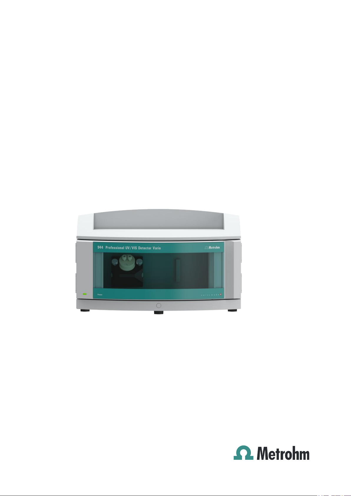
944 Professional UV/VIS Detector Vario
2.944.0010
Manual
8.944.8001EN
Page 2

Page 3

Metrohm AG
CH-9100 Herisau
Switzerland
Phone +41 71 353 85 85
Fax +41 71 353 89 01
info@metrohm.com
www.metrohm.com
944 Professional UV/VIS Detector
Vario
2.944.0010
8.944.8001EN
Manual
11.2013 zst
Page 4

Teachware
Metrohm AG
CH-9100 Herisau
teachware@metrohm.com
This documentation is protected by copyright. All rights reserved.
Although all the information given in this documentation has been
checked with great care, errors cannot be entirely excluded. Should you
notice any mistakes please send us your comments using the address
given above.
Documentation in additional languages can be found on
http://documents.metrohm.com.
Page 5

■■■■■■■■■■■■■■■■■■■■■■
Table of contents
1 Introduction 1
1.1 Instrument description ......................................................... 1
1.2 Intended use ......................................................................... 1
1.3 About the documentation ................................................... 1
1.3.1 Symbols and conventions ........................................................ 2
1.4 Safety instructions ................................................................ 3
1.4.1 General notes on safety ........................................................... 3
1.4.2 Electrical safety ........................................................................ 3
1.4.3 Tubing and capillary connections ............................................. 4
1.4.4 Flammable solvents and chemicals ........................................... 4
1.4.5 Recycling and disposal ............................................................. 4
2 Overview of the instrument 6
2.1 Front ...................................................................................... 6
Table of contents
2.2 Rear ........................................................................................ 7
3 Installation 8
3.1 Setting up the instrument .................................................... 8
3.1.1 Packaging ................................................................................ 8
3.1.2 Checks .................................................................................... 8
3.1.3 Location .................................................................................. 8
3.2 Setup configurations ............................................................ 8
3.3 Base tray and bottle holder ............................................... 10
3.3.1 Basic information on base tray and bottle holder ................... 10
3.3.2 Mounting base tray and bottle holder (optional) .................... 10
3.4 Installing the flow-through cell ......................................... 15
3.5 Connecting the flow-through cell ..................................... 17
3.6 Connecting the instrument ................................................ 19
3.6.1 Connecting the instrument to a computer ............................. 19
3.6.2 Connecting the instrument to the power supply .................... 19
4 Start-up 21
5 Operation 23
6 Operation and maintenance 24
6.1 Care ...................................................................................... 24
6.2 Maintenance by Metrohm Service .................................... 24
6.3 Door ..................................................................................... 25
944 Professional UV/VIS Detector Vario (2.944.0010)
■■■■■■■■
III
Page 6

Table of contents
■■■■■■■■■■■■■■■■■■■■■■
6.4 Replacing the UV lamp ....................................................... 25
6.5 Replacing the VIS lamp ...................................................... 28
6.6 Adjusting the lamp settings .............................................. 28
6.7 Cleaning the flow-through cell .......................................... 29
6.8 Quality Management and qualification with
Metrohm ............................................................................. 33
7 Troubleshooting 34
7.1 Problems and their solutions ............................................. 34
8 Technical specifications 35
8.1 Reference conditions .......................................................... 35
8.2 UV/VIS detector .................................................................. 35
8.3 Lamps .................................................................................. 37
8.4 Ambient conditions ............................................................ 37
8.5 Housing ............................................................................... 37
8.6 Power connection ............................................................... 38
8.7 Interfaces ............................................................................. 38
8.8 Safety specifications ........................................................... 38
8.9 Electromagnetic compatibility (EMC) ................................ 39
8.10 Weight ................................................................................. 39
9 Warranty (guarantee) 40
10 Accessories 42
Index 44
■■■■■■■■
IV
944 Professional UV/VIS Detector Vario (2.944.0010)
Page 7

■■■■■■■■■■■■■■■■■■■■■■
Table of figures
Figure 1 Front ................................................................................................. 6
Figure 2 Rear .................................................................................................. 7
Figure 3 Setup configurations ......................................................................... 9
Figure 4 Cell block ........................................................................................ 15
Figure 5 Connecting the detector input ......................................................... 17
Figure 6 Connecting the detector outlet ........................................................ 18
Figure 7 Intensity spectrum OK ..................................................................... 22
Figure 8 Lamp intensity too high ................................................................... 22
Figure 9 Operating hours counter ................................................................. 25
Figure 10 Lamp module .................................................................................. 25
Figure 11 Lamp module – without UV lamp .................................................... 27
Figure 12 Flow-through cell – parts ................................................................. 31
Table of figures
944 Professional UV/VIS Detector Vario (2.944.0010)
■■■■■■■■
V
Page 8

Page 9

■■■■■■■■■■■■■■■■■■■■■■
1 Introduction
1.1 Instrument description
The 944 Professional UV/VIS Detector Vario is an independent instrument for the photometric determination of light-absorbing substances in
the UV/VIS range. It serves as UV/VIS detector within an ion chromatography system.
The 944 Professional UV/VIS Detector Vario is operated with the
MagIC Net software. It is connected to a PC on which MagIC Net is
installed with a USB cable. The software detects the instrument automatically and checks its functionality. MagIC Net controls and monitors the
instrument, evaluates the measured data and manages it in a database.
Additional information on operating MagIC Net can be found in the document "MagIC Net Tutorial" or in the software's online help.
1 Introduction
1.2 Intended use
The 944 Professional UV/VIS Detector Vario is used as an independent
detector with various analysis instruments of the Metrohm line of instruments.
The present instrument is suitable for processing chemicals and flammable
samples. Usage of the 944 Professional UV/VIS Detector Vario therefore
requires the user to have basic knowledge and experience in handling
toxic and caustic substances. Knowledge with respect to the application
of the fire prevention measures prescribed for laboratories is also mandatory.
1.3 About the documentation
CAUTION
Please read through this documentation carefully before putting the
instrument into operation. The documentation contains information
and warnings which the user must follow in order to ensure safe operation of the instrument.
944 Professional UV/VIS Detector Vario (2.944.0010)
■■■■■■■■
1
Page 10
1.3 About the documentation
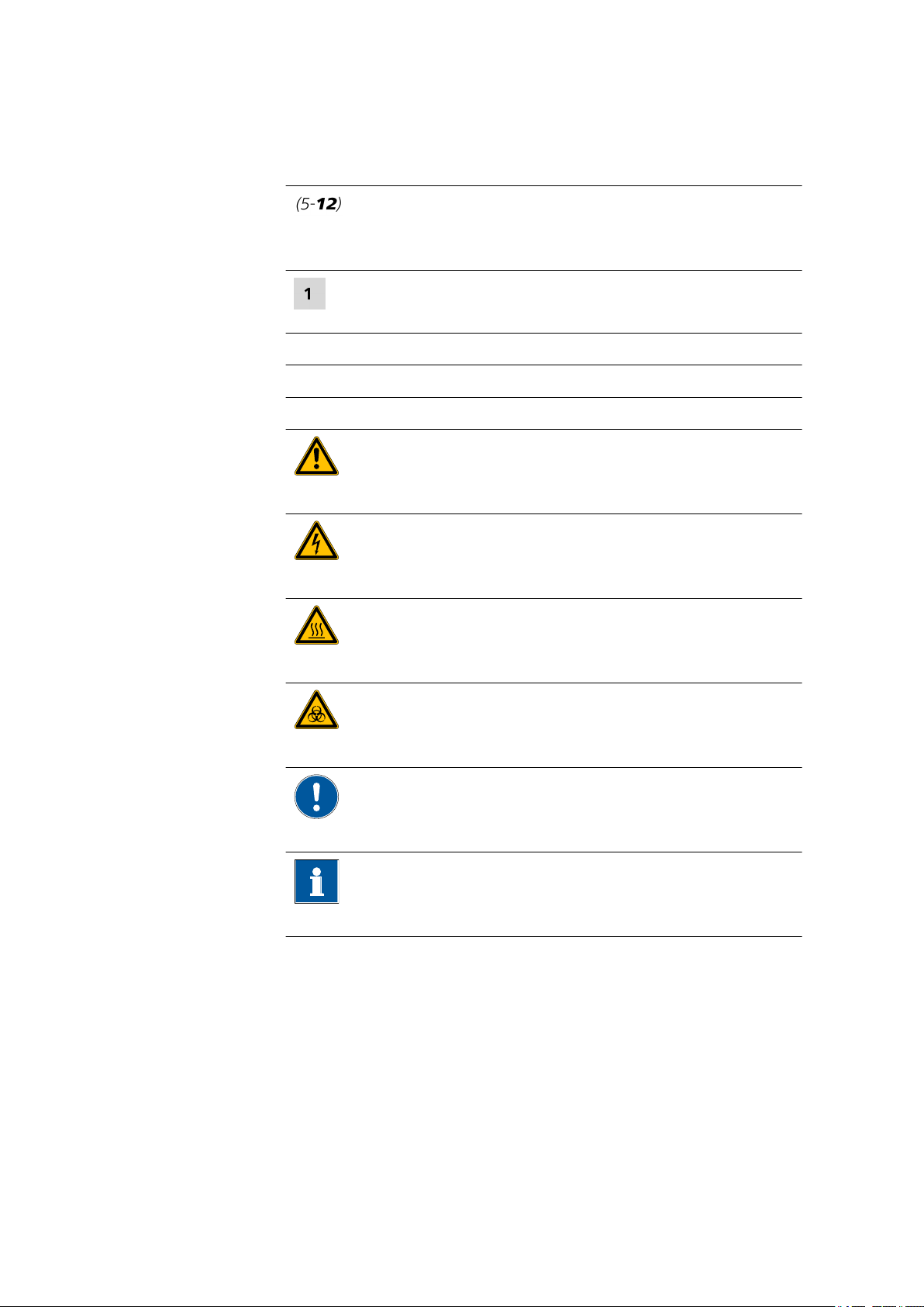
1.3.1 Symbols and conventions
The following symbols and formatting may appear in this documentation:
Method Dialog text, parameter in the software
File ▶ New Menu or menu item
[Next] Button or key
■■■■■■■■■■■■■■■■■■■■■■
Cross-reference to figure legend
The first number refers to the figure number, the second to the instrument part in the figure.
Instruction step
Carry out these steps in the sequence shown.
WARNING
This symbol draws attention to a possible life-threatening hazard or risk of injury.
WARNING
This symbol draws attention to a possible hazard due
to electrical current.
WARNING
This symbol draws attention to a possible hazard due
to heat or hot instrument parts.
WARNING
This symbol draws attention to a possible biological
hazard.
CAUTION
This symbol draws attention to possible damage to
instruments or instrument parts.
NOTE
This symbol highlights additional information and
tips.
■■■■■■■■
2
944 Professional UV/VIS Detector Vario (2.944.0010)
Page 11
■■■■■■■■■■■■■■■■■■■■■■
1.4 Safety instructions
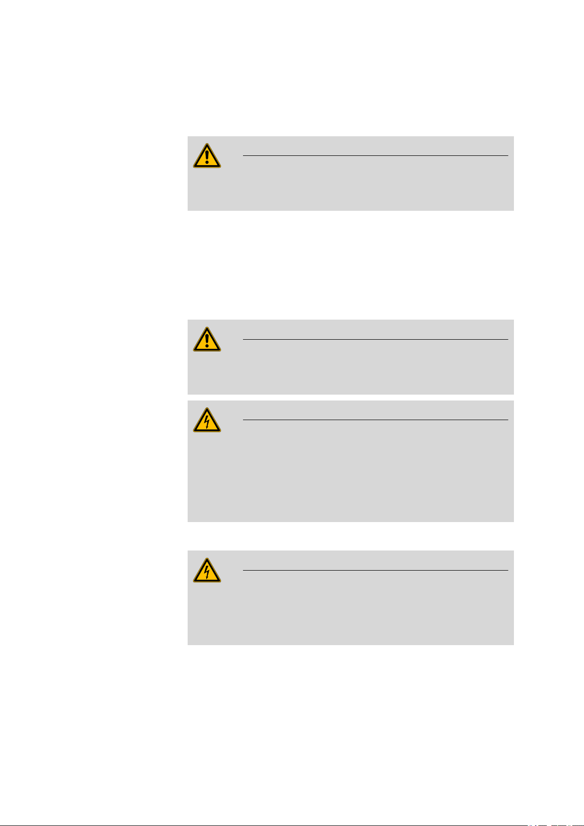
1.4.1 General notes on safety
WARNING
This instrument may only be operated in accordance with the specifications in this documentation.
This instrument has left the factory in a flawless state in terms of technical
safety. To maintain this state and ensure non-hazardous operation of the
instrument, the following instructions must be observed carefully.
1.4.2 Electrical safety
The electrical safety when working with the instrument is ensured as part
of the international standard IEC 61010.
WARNING
1 Introduction
Only personnel qualified by Metrohm are authorized to carry out service
work on electronic components.
WARNING
Never open the housing of the instrument. The instrument could be
damaged by this. There is also a risk of serious injury if live components
are touched.
There are no parts inside the housing which can be serviced or replaced
by the user.
Mains voltage
WARNING
An incorrect mains voltage can damage the instrument.
Only operate this instrument with a mains voltage specified for it (see
rear panel of the instrument).
944 Professional UV/VIS Detector Vario (2.944.0010)
■■■■■■■■
3
Page 12
1.4 Safety instructions
Protection against electrostatic charges
WARNING
Electronic components are sensitive to electrostatic charges and can be
destroyed by discharges.
Do not fail to pull the mains cable out of the mains connection socket
before you set up or disconnect electrical plug connections at the rear
of the instrument.
1.4.3 Tubing and capillary connections
CAUTION
Leaks in tubing and capillary connections are a safety risk. Tighten all
connections well by hand. Avoid applying excessive force to tubing
connections. Damaged tubing ends lead to leakage. Appropriate tools
can be used to loosen connections.
■■■■■■■■■■■■■■■■■■■■■■
Check the connections regularly for leakage. If the instrument is used
mainly in unattended operation, then weekly inspections are mandatory.
1.4.4 Flammable solvents and chemicals
WARNING
All relevant safety measures are to be observed when working with
flammable solvents and chemicals.
■ Set up the instrument in a well-ventilated location (e.g. fume cup-
board).
■ Keep all sources of flame far from the workplace.
■ Clean up spilled liquids and solids immediately.
■ Follow the safety instructions of the chemical manufacturer.
1.4.5 Recycling and disposal
This product is covered by European Directive 2002/96/EC, WEEE – Waste
from Electrical and Electronic Equipment.
■■■■■■■■
4
The correct disposal of your old equipment will help to prevent negative
effects on the environment and public health.
944 Professional UV/VIS Detector Vario (2.944.0010)
Page 13

■■■■■■■■■■■■■■■■■■■■■■
1 Introduction
More details about the disposal of your old equipment can be obtained
from your local authorities, from waste disposal companies or from your
local dealer.
944 Professional UV/VIS Detector Vario (2.944.0010)
■■■■■■■■
5
Page 14

2.1 Front
1
2
2 Overview of the instrument
2.1 Front
■■■■■■■■■■■■■■■■■■■■■■
Figure 1 Front
Flow-through cell
1
Standby indicator
2
■■■■■■■■
6
944 Professional UV/VIS Detector Vario (2.944.0010)
Page 15
■■■■■■■■■■■■■■■■■■■■■■
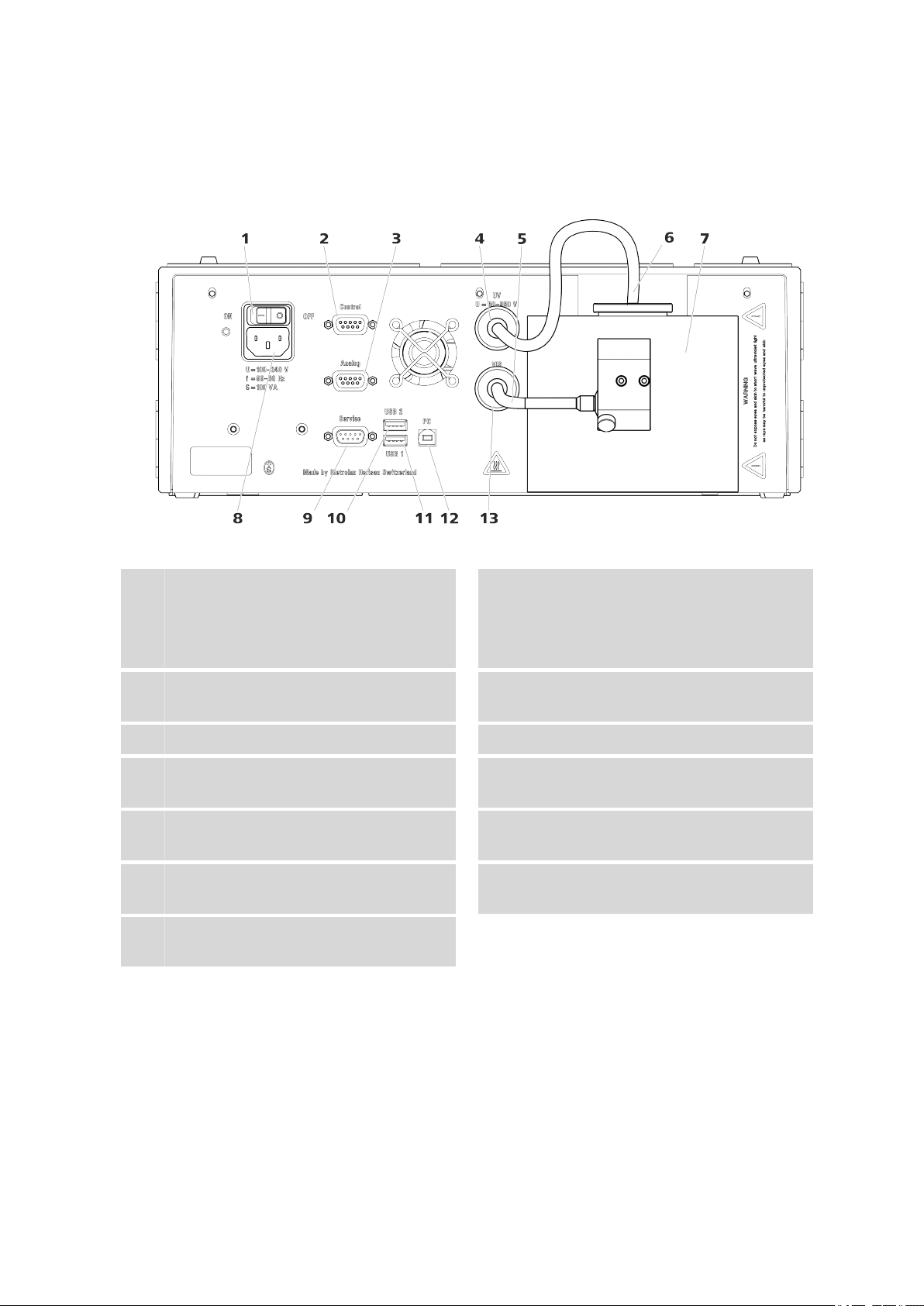
2.2 Rear
2 Overview of the instrument
Figure 2 Rear
Power switch
1
For switching the instrument on and off.
I = On
O = Off
Analog connection socket
3
Output for analog signals.
VIS lamp connection cable
5
Lamp cooling element
7
Service connection socket
9
Connector for service.
USB 1 connection socket
11
For connecting additional USB devices.
VIS connection socket
13
For connecting the cable of the VIS lamp.
Control connection socket
2
Not Used.
UV connection socket
4
For connecting the cable of the UV lamp.
UV lamp connection cable
6
Power socket
8
For connecting the power supply cable.
USB 2 connection socket
10
For connecting additional USB devices.
PC connection socket
12
For connecting the USB cable to the PC.
944 Professional UV/VIS Detector Vario (2.944.0010)
■■■■■■■■
7
Page 16

3.1 Setting up the instrument
3 Installation
3.1 Setting up the instrument
3.1.1 Packaging
The instrument is supplied in highly protective special packaging together
with the separately packed accessories. Keep this packaging, as only this
ensures safe transportation of the instrument.
3.1.2 Checks
Immediately after receipt, check whether the shipment has arrived complete and without damage by comparing it with the delivery note.
3.1.3 Location
The instrument has been developed for operation indoors and may not be
used in explosive environments.
■■■■■■■■■■■■■■■■■■■■■■
Place the instrument in a location of the laboratory which is suitable for
operation and free of vibrations and which provides protection against
corrosive atmosphere and contamination by chemicals.
The instrument should be protected against excessive temperature fluctuations and direct sunlight.
The distance between the rear of the instrument and the wall must be
large enough to ensure air circulation on the cooling plate.
3.2 Setup configurations
The 944 Professional UV/VIS Detector Vario can be used as a detector
with the instruments of the 940 Professional IC Vario and 930 Compact IC
Flex family. For many applications with photometric detection, a post-column derivatization with the 943 Professional Thermostat / Reactor Vario
(2.943.0110) is required. To build such a system, you will need a 944 Professional UV/VIS Detector Vario and the following instruments:
■ any 940 Professional IC Vario, or
any 930 Compact IC Flex
■ a 943 Professional Thermostat / Reactor Vario
■ optionally: a 942 Extension Module Vario for sample preparation
■ optionally, if the reagent is pumped with a high-pressure pump: a Met-
rosep BP 1 Guard/2.0 backpressure column (6.1015.100)
■■■■■■■■
8
An IC system with photometric detection and post-column derivatization
can be set up in in various configurations.
944 Professional UV/VIS Detector Vario (2.944.0010)
Page 17

■■■■■■■■■■■■■■■■■■■■■■
2.944.0010
2.943.0110
2.940.xxxx
2.942.xxxx
2.940.xxxx
2.942.xxxx
2.944.0010
2.943.0110
6.2061.100
6.2061.110
2.940.xxxx
2.930.xxxx
2.944.0010
2.943.0110
2.942.xxxx
6.2061.110
6.2061.100
2.930.xxxx
6.2061.120
2.942.xxxx
6.2061.100
2.944.0010
2.943.0110
6.2061.110
3 Installation
Figure 3 Setup configurations
Notes on the setup configurations
If you want to set up the instruments in two stacks, we recommend you
order the following accessories to protect the instruments of the second
stack:
■ Bottle holder (ProfIC) (6.2061.100)
■ Base tray with sensor for Professional IC instruments (6.2061.110)
If you would like to stack a 930 Compact IC Flex on a 944 Professional
UV/VIS Detector Vario, a 943 Professional Thermostat / Reactor Vario and/
or a 942 Extension Module Vario, then you will need the System Connector (6.2061.120) to accommodate the different base sizes.
944 Professional UV/VIS Detector Vario (2.944.0010)
■■■■■■■■
9
Page 18

3.3 Base tray and bottle holder
■■■■■■■■■■■■■■■■■■■■■■
3.3 Base tray and bottle holder
3.3.1 Basic information on base tray and bottle holder
The base tray (6.2061.110) and bottle holder (6.2061.100) protect IC
instruments from dust, dirt and leaking fluids. The supply bottles for eluent
and auxiliary solutions can be positioned neatly on the bottle holder.
In a complex IC system, several different instruments may be used, such as
an analyzer, an extension module and a detector. These instruments can
be set up in one or more stacks. We recommend that a base tray and bottle holder be mounted for each stack of IC instruments.
The bottle holder and base tray must be removed or set up every time one
of the following instruments is to be mounted on or under a 940 Professional IC Vario:
■ One or more 942 Extension Module Vario.
■ Or another instrument with the same-sized footprint.
3.3.2 Mounting base tray and bottle holder (optional)
The base tray and bottle holder come fully assembled on a new ion chromatograph. If you wished to install an extension module on the ion chromatograph, you would have to remove the bottle holder and put it back
on top of the topmost instrument. If you wished to install an extension
module below the ion chromatograph, you would have to remove the
base tray and set it under the lowest instrument.
3.3.2.1
Removing/mounting the base tray
The base tray must be removed if you want to install another instrument
under the IC instrument.
CAUTION
Do not allow capillaries or leak sensor cables to be pinched!
Pinches in the leak sensor cable or the capillaries fed through the guide
ducts between the base tray and the instrument may lead to malfunctions.
Unplug the leak sensor cable. Remove all of the capillaries from the
capillary ducts.
■■■■■■■■
10
Removing the base tray
Before you can remove the base tray, the following preconditions must be
met:
944 Professional UV/VIS Detector Vario (2.944.0010)
Page 19

■■■■■■■■■■■■■■■■■■■■■■
1
2
3
3 Installation
■ The instrument is switched off.
■ The bottle holder is cleared.
■ All of the cable connections on the rear have been disconnected.
■ The capillaries are removed from the guide ducts between the instru-
ment and the base tray.
■ There are no loose parts in the instrument.
To remove the base tray, you need a 3 mm hex key (6.2621.100).
Tilt the instrument sideways and lay it down flat.
1
Loosen the four cylinder screws with the 3 mm hex key and remove
2
them and their washers.
Remove the base tray.
3
The base tray must always be mounted under the lowermost instrument
of the stack.
Mounting the base tray
Before you can mount the base tray, the following preconditions must be
met:
■ The instrument is switched off.
■ The bottle holder is cleared.
■ All of the cable connections on the rear have been disconnected.
■ There are no loose parts in the instrument.
■ The instrument is lying on its side, and the bottom surface is visible.
To mount the base tray, you need a 3 mm hex key (6.2621.100).
944 Professional UV/VIS Detector Vario (2.944.0010)
■■■■■■■■
11
Page 20

3.3 Base tray and bottle holder
1
3
2
■■■■■■■■■■■■■■■■■■■■■■
Place the base tray in such a way that the openings in the base tray
1
match exactly the screw threads in the bottom of the instrument.
Slide the washers onto the cylinder screws, insert the screws and
2
tighten them with the 3 mm hex key.
Set the instrument back up on the base tray.
3
3.3.2.2
Stack other instruments in the required order. Mount the bottle holder
(6.2061.100) onto the topmost instrument on the stack (see "Mounting
the bottle holder", page 14).
Removing/mounting the bottle holder
The bottle holder must be removed if you want to install another instrument onto the IC instrument.
Removing the bottle holder
Before you can remove the bottle holder, the following preconditions
must be met:
■ The instrument is switched off.
■ The bottle holder is cleared.
■ Drainage tubing is disconnected from the drainage tubing connection
of the bottle holder.
■ The capillaries are removed from the guide ducts between the instru-
ment and the bottle holder.
To remove the bottle holder, you need a 3 mm hex key (6.2621.100).
■■■■■■■■
12
944 Professional UV/VIS Detector Vario (2.944.0010)
Page 21

■■■■■■■■■■■■■■■■■■■■■■
1
2 3
Remove the two covering stoppers.
1
Loosen the two cylinder screws with the 3 mm hex key and remove
2
them.
Remove the bottle holder.
3
3 Installation
Stack other instruments in the required order. Mount the bottle holder
(6.2061.100) onto the topmost instrument on the stack.
944 Professional UV/VIS Detector Vario (2.944.0010)
■■■■■■■■
13
Page 22

3.3 Base tray and bottle holder
1
2 3
■■■■■■■■■■■■■■■■■■■■■■
Mounting the bottle holder
Before you can mount the bottle holder, the following preconditions must
be met:
■ The instrument is switched off.
To mount the bottle holder, you need a 3 mm hex key (6.2621.100).
Place the bottle holder onto the topmost instrument in such a way
1
that the openings in the bottle holder exactly match the screw
threads on the top surface of the instrument.
Insert the two cylinder screws and tighten them with the 3 mm hex
2
key.
Insert both covering stoppers.
3
After attaching the bottle holder, all connections that were undone at the
beginning of the process must be reconnected.
Restoring the loosened connections
Plug in all necessary USB cables.
1
Plug in all necessary MSB cables.
2
Plug in the power supply cable.
3
Mount the drainage tubing again (see manual of the IC instrument).
4
■■■■■■■■
14
944 Professional UV/VIS Detector Vario (2.944.0010)
Page 23

■■■■■■■■■■■■■■■■■■■■■■
1
2
3
3
4
A longer section of silicone tubing (6.1816.020) may have to be cut
to size and mounted (see also the manual for the IC instrument).
If one of the instruments in the stack is equipped with a leak sensor
5
connection socket, connect the leak sensor (see manual of the IC
instrument).
Restore any capillary connections that may have been removed.
6
3.4 Installing the flow-through cell
3 Installation
Cell holder
1
Holder for the flow-through cell.
Knurled screws
3
Figure 4
Cell block
Cover plate
2
Protects the cell holder form contamination
if no cell is installed.
Cylinder screw
4
For the correct alignment of the flowthrough cell.
944 Professional UV/VIS Detector Vario (2.944.0010)
■■■■■■■■
15
Page 24

3.4 Installing the flow-through cell
1
2
3
4
■■■■■■■■■■■■■■■■■■■■■■
Installing the flow-through cell
Loosen and remove the knurled screws (4-3).
1
Remove the cover plate (4-2).
2
Insert the flow-through cell (6.2839.130) such that the opening in
3
top right corner is aligned with the cylinder screw (4-4) on the cell
block.
Screw in the knurled screws again.
4
NOTE
In order to fix the flow-through cell in the correct position, the
two knurled screws must be tightened symmetrically and with
constant force.
Any tilting, twisting or canting of the flow-through cell influences
the light incidence and thus the measuring results.
■■■■■■■■
16
944 Professional UV/VIS Detector Vario (2.944.0010)
Page 25

■■■■■■■■■■■■■■■■■■■■■■
2
1
3
3.5 Connecting the flow-through cell
To connect the capillaries to the flow-through cell, proceed as follows:
Connecting the capillaries
1
Connecting the detector input
3 Installation
Detector input capillary
1
PEEK capillary (6.1831.100).
Pressure screw
3
Figure 5 Connecting the detector input
Detector inlet
2
Labeled IN.
■ Unscrew the pressure screw from the IN detector inlet.
■ Slide the presssure screw over the detector input capillary such
that a small part of the capillary is visible at the top.
■ Tighten the detector input capillary in the detector inlet using the
pressure screw.
944 Professional UV/VIS Detector Vario (2.944.0010)
■■■■■■■■
17
Page 26

3.5 Connecting the flow-through cell
3
4
1
2
2
Connecting the detector outlet
Figure 6 Connecting the detector outlet
■■■■■■■■■■■■■■■■■■■■■■
Detector input capillary
1
Detector outlet
3
Labeled OUT.
Detector output capillary
2
PEEK capillary (6.1831.100).
Pressure screw
4
■ Unscrew the pressure screw form the OUT detector outlet.
■ Slide the presssure screw over the detector output capillary such
that a small part of the capillary is visible at the top.
■ Screw the detector output capillary to the detector outlet with the
pressure screw.
NOTE
The detector output capillary (6.1831.100) is 1 m long and may
not be shortened.
■■■■■■■■
18
944 Professional UV/VIS Detector Vario (2.944.0010)
Page 27

■■■■■■■■■■■■■■■■■■■■■■
3.6 Connecting the instrument
3.6.1 Connecting the instrument to a computer
NOTE
The instrument must be switched off when being connected to a computer.
Accessories For this step you need the following accessories:
■ USB connecting cable (6.2151.020)
Insert the USB cable into the computer connection socket on the rear
1
of the instrument labeled PC.
Insert the other end into a USB port on the computer.
2
3 Installation
3.6.2 Connecting the instrument to the power supply
WARNING
The power supply unit must not get wet. Protect it from liquids.
The power supply cable is three-core and provided with a plug with
grounding. If another plug has to be mounted, the yellow/green conductor (IEC standard) must be connected to the protective ground (protection
class I).
Accessories
For this step you need the following accessories:
■ For Switzerland, …: Power supply cable with IEC 60320 line socket,
type C13, with SEV 1011 plug, type 12 (6.2122.020), 1.5 m
■ For Germany, …: Power supply cable with IEC 60320 line socket, type
C13, with CEE 7 plug, type VII (6.2122.040), 1.5 m
■ For the USA, …: Power supply cable with IEC 60320 line socket, type
C13, with NEMA 5-15 plug, type 498 (6.2122.070), 1.5 m
Connecting the power supply cable
1
Plugging in the power supply cable
■ Plug the power supply cable into the instrument's power socket.
■ Connect the power supply cable to the power supply.
944 Professional UV/VIS Detector Vario (2.944.0010)
■■■■■■■■
19
Page 28

3.6 Connecting the instrument
■■■■■■■■■■■■■■■■■■■■■■
2
Switching on the instrument
Switch on the instrument using the power switch.
After being switched on, the LED on the front of the instrument
flashes. The instrument conducts a system test and establishes a connection to the software. Once the system test is complete and the
connection to the software has been established, the LED lights up
continuously.
■■■■■■■■
20
944 Professional UV/VIS Detector Vario (2.944.0010)
Page 29

■■■■■■■■■■■■■■■■■■■■■■
4 Start-up
4 Start-up
The 944 Professional UV/VIS Detector Vario is put into operation together
with the IC instrument.
The following preconditions must be met before initial start-up:
■ The 944 Professional UV/VIS Detector Vario is installed as outlined in
this manual and connected to the ion chromatograph.
You can find additional information on carrying out initial start-up in the
Start-up chapter in the manual for the IC instrument and the MagIC Net
online help.
We recommend checking the intensity spectrum of the lamps in addition
to performing the initial start-up with the IC system.
Checking the intensity spectrum
Before you can check the intensity of the lamps, the following preconditions must be met:
■ The lenses and the flow path of the flow-through cell must be clean.
1
Rinsing the flow-through cell with ultrapure water
Rinse the flow-through cell with ultrapure water at a flow rate of
0.5 mL/min.
Ensure that no air bubbles remain in the flow-through cell.
2
Checking the intensity of the lamps
In MagIC Net, adjust the following settings:
■ Go to the Manual program part.
■ Click on the icon for the 944 UV/VIS Detector.
■ On the UV lamp tab, switch on the UV Lamp.
■ On the VIS lamp tab, switch on the VIS lamp.
■ On the Detector tab, select the Intensity spectrum.
First click on [Reset baseline] and then click on [View].
The lamp's intensity range is monitored and the spectrum is
recorded.
If the intensity spectrum looks similar to the spectrum in Figure 7, then the
lamp is correctly adjusted.
944 Professional UV/VIS Detector Vario (2.944.0010)
■■■■■■■■
21
Page 30

■■■■■■■■■■■■■■■■■■■■■■
Figure 7 Intensity spectrum OK
If the intensity spectrum is cut off like the one in Figure 8, then the lamp
settings must be adjusted (see Chapter 6.6, page 28).
Figure 8
Lamp intensity too high
■■■■■■■■
22
944 Professional UV/VIS Detector Vario (2.944.0010)
Page 31

■■■■■■■■■■■■■■■■■■■■■■
5 Operation
5 Operation
The instrument is operated via MagIC Net software only. Additional information on operating MagIC Net can be found in the document
"MagIC Net Tutorial" or in the software's online help.
944 Professional UV/VIS Detector Vario (2.944.0010)
■■■■■■■■
23
Page 32

6.1 Care
6 Operation and maintenance
6.1 Care
The instrument requires appropriate care. Excess contamination of the
instrument may result in malfunctions and a reduction in the lifetime of
the sturdy mechanical and electronic components.
The instrument must be cleaned immediately if chemicals or solvents are
spilled on it. In particular, the plug connections (particularly the power
plug) have to be protected from contamination.
CAUTION
The instrument has been designed so that liquid is largely prevented
from being able to get inside the instrument. However, unplug the
power plug immediately if you suspect that corrosive media have gotten inside the instrument. This is the only way to prevent extreme damage to the instrument electronics. Notify Metrohm Service.
■■■■■■■■■■■■■■■■■■■■■■
WARNING
Untrained personnel may not open the instrument's housing.
6.2 Maintenance by Metrohm Service
Maintenance of the instrument is best carried out as part of annual service, which is performed by specialist personnel from Metrohm. A shorter
maintenance interval is recommended if you frequently work with caustic
and corrosive chemicals. Metrohm Service offers every form of technical
advice for maintenance and service of all Metrohm instruments.
■■■■■■■■
24
944 Professional UV/VIS Detector Vario (2.944.0010)
Page 33

■■■■■■■■■■■■■■■■■■■■■■
0
2000
HOURS
1
2
3
4
5
6.3 Door
CAUTION
The door is made of PMMA (poly(methyl methacrylate)). It must never
be cleaned with abrasive media or solvents.
CAUTION
Never hold the instrument by the door when lifting or moving it.
6.4 Replacing the UV lamp
After a a prolonged burning time, the radiation of the UV lamp starts to
decrease, which can be noticed by an increased noise on the baseline.
Check the effective burning time on the operating hours counter fixed to
the cable of the lamp. This counter measures the effective hours of operation and displays them on a scale.
6 Operation and maintenance
Figure 9
Operating hours counter
The UV lamp must be replaced if the noise on the baseline becomes too
strong or when the lamp does not ignite.
Figure 10
Lamp cooling element
1
Lamp module
VIS lamp holder
2
944 Professional UV/VIS Detector Vario (2.944.0010)
■■■■■■■■
25
Page 34

6.4 Replacing the UV lamp
1
2
3
■■■■■■■■■■■■■■■■■■■■■■
VIS lamp
3
Halogen lamp (6.2804.050).
Fastening ring
5
For UV lamp.
UV lamp
4
Deuterium lamp (6.2804.060) with operating hours counter.
Removing the old UV lamp
WARNING
After longer operation, the UV lamp becomes hot!
Risk of burns!
Switch off the instrument and allow the lamp to cool before you start
working.
1
Disconnecting the UV lamp
Loosen the retaining ring of the UV lamp plug and pull the plug out
of the UV connection socket.
2
Loosening the fastening ring
Loosen and remove the fastening ring of the UV lamp.
3
Removing the UV lamp
Carefully remove the old UV lamp from the housing.
■■■■■■■■
26
944 Professional UV/VIS Detector Vario (2.944.0010)
Page 35

■■■■■■■■■■■■■■■■■■■■■■
1
2
3
4
3
2
1
6 Operation and maintenance
Figure 11 Lamp module – without UV lamp
Lamp cooling element
1
VIS lamp
3
VIS lamp holder
2
Opening
4
For UV lamp.
Inserting the new UV lamp
CAUTION
Do not touch the glass of the UV lamp!
Residues on the glass diminish light transmission. In addition, they can
burn into the glass and permanently damage the lamp.
If the glass is dirty, clean it with alcohol before inserting the lamp again.
1
Inserting the UV lamp
Insert the new UV lamp (6.2804.060) into the opening for the UV
lamp on the lamp cooling element.
When doing so, make sure that the groove on the lamp socket and
the screw in the lamp cooling element are aligned with each other.
944 Professional UV/VIS Detector Vario (2.944.0010)
■■■■■■■■
27
Page 36

6.5 Replacing the VIS lamp
2
Fastening the UV lamp
Slide the fastening ring over the cable of the UV lamp and screw it to
the lamp cooling element.
3
Connecting the UV lamp
Plug the plug of the UV Lamp into the connection socket UV of the
instrument and secure it with the fastening ring.
6.5 Replacing the VIS lamp
NOTE
A description on how to replace the VIS lamp (6.2804.050) is described
in the leaflet supplied with the VIS lamp.
■■■■■■■■■■■■■■■■■■■■■■
6.6 Adjusting the lamp settings
The lamp settings are set correctly at delivery.
CAUTION
The lamp settings may be adjusted only in the following cases:
■ After initial start-up, if the the check of the intensity spectrum shows
a cut-off (see Figure 8, page 22).
■ After having replaced the UV lamp (see Chapter 6.4, page 25) or the
VIS lamp (see Chapter 6.5, page 28), if the check of the intensity
spectrum shows a cut-off (see Figure 8, page 22).
Before each adjustment of the lamp values, it is mandatory to check the
intensity spectrum. The lamp settings may only be adjusted if the intensity
spectrum is cut off at the top.
Adjusting the lamp settings
Before you can adjust the lamp settings, all the following preconditions
must be unconditionally met:
■■■■■■■■
28
■ The UV lamp has been burning for at least 30 minutes.
■ The flow-through cell is clean.
■ The flow-through cell is rinsed with ultrapure water.
■ The flow-through cell is free of air bubbles.
944 Professional UV/VIS Detector Vario (2.944.0010)
Page 37

■■■■■■■■■■■■■■■■■■■■■■
6 Operation and maintenance
■ The intensity spectrum has been checked and shows a cut-off (see Fig-
ure 8, page 22).
1
Starting the automatic lamp setting
■ In MagIC Net, select the 944 UV/VIS Detector from the device
table in the Configuration program part.
■ Click on Edit ▶ Properties... to open the properties window.
■ On the Detector tab, click on [Settings] to open the detector
settings.
■ In the detector settings, click on [Adjust automatically] to start
the automatic lamp adjustment.
The lamp settings are made based on a built-in algorithm. This algorithm calculates and sets the optimized values for Integration dura-
tion and VIS intensity level. After the automatic adjustment, a
new intensity spectrum is displayed.
2
Saving the lamp settings
■ Check the new intensity spectrum that is displayed and click on
[OK] to complete the lamp optimization.
The adjusted lamp values are transferred to the instrument. The dialog window is closed.
6.7 Cleaning the flow-through cell
Depending on the application, hardly visible deposits may form on the lenses, which leads to higher absorption and thus increasing noise on the
baseline.
If the baseline is very noisy and the problem is not caused by other parts
of the system, the flow-through cell must be cleaned.
For the cleaning of the flow-through cell, we recommend a three-step
process:
1. Rinse the flow-through cell with methanol.
2. Rinse the flow-through cell with a different solvent.
3. Dismantle the flow-through cell and clean it manually.
Always start the cleaning process with step 1. If this does not solve the
problem, perform step 2. Perform step 3 only if the deposits are persistent.
Rinsing the flow-through cell with methanol
Disconnect the input capillary from the IC system.
1
944 Professional UV/VIS Detector Vario (2.944.0010)
■■■■■■■■
29
Page 38

6.7 Cleaning the flow-through cell
■■■■■■■■■■■■■■■■■■■■■■
Connect the input capillary to a high-pressure pump or a peristaltic
2
pump and rinse the flow-through cell as described below; make sure
that the permissible maximum pressure of 5 MPa is not exceeded:
■ first rinse with ultrapure water to avoid precipitates,
■ then rinse several minutes with methanol, to dissolve the deposits,
and
■ finally, rinse with ultrapure water for at least another 15 minutes
to wash away the dissolved deposits.
Observe the baseline during the last rinsing with ultrapure water.
3
If the baseline is only slightly noisy, then the flow-through cell is
clean.
If the noise on the baseline persists, rinse the flow-through cell once
again with another solvent (see "Rinsing the flow-through cell with
another solvent", page 30).
Rinsing the flow-through cell with another solvent
A solvent made up of a 1:2 mixture of acetic acid and isopropanol has
shown good results. Depending on the application, other solvents may
also prove efficient.
Prerequisites:
■ Rinsing with methanol was ineffective.
■ The input capillary is connected to a high-pressure pump or a peristaltic
pump.
Rinse the flow-through cell as described below; make sure that the
1
maximum permissible pressure of 5 MPa is not exceeded:
■ first rinse with ultrapure water to avoid precipitates,
■ then rinse several minutes with the selected solvent to dissolve
the deposits, and
■ finally, rinse with ultrapure water for at least another 15 minutes
to wash away the dissolved deposits.
Observe the baseline during the last rinsing.
2
■■■■■■■■
30
If the baseline is only slightly noisy, then the flow-through cell is
clean.
If the noise on the baseline persists, the flow-through cell must be
dismantled and cleaned manually (see "Dismantling and cleaning the
flow-through cell", page 31).
944 Professional UV/VIS Detector Vario (2.944.0010)
Page 39

■■■■■■■■■■■■■■■■■■■■■■
5
4
3
1
4
3
1
2
6
6 Operation and maintenance
Dismantling and cleaning the flow-through cell
NOTE
Ex works, the retaining screws are tightened with a torque wrench. This
guarantees a pressure stability up to 5 MPa (50 bar).
Once the flow-through cell has been opened and closed again, this
maximum pressure stability can no longer be guaranteed.
Prerequisites:
■ Rinsing the flow-through cell with solvent was ineffective.
Required tools:
■ To open the measuring cell, you need a slotted screwdriver, size 5.
■ Seals (6.2764.000).
1
Removing the flow-through cell
■ Unscrew the input capillary and the output capillary.
■ Loosen and remove the knurled screws.
■ Remove the flow-through cell from the optical block.
Figure 12 Flow-through cell – parts
Retaining screw
1
Lens
3
Measuring cell – opening
5
944 Professional UV/VIS Detector Vario (2.944.0010)
2
4
6
Outer seal
Inner seal
Cell holder
■■■■■■■■
31
Page 40

6.7 Cleaning the flow-through cell
■■■■■■■■■■■■■■■■■■■■■■
2
Removing the lens
■ Loosen the retaining screw (12-1) with a slotted screwdriver, size
5, and remove it.
Remove the seal from the inside of the retaining screw (12-2).
■ Carefully remove the lens (12-3) and the inner seal (12-4) from
the measuring cell.
■ Put the lens onto a white paper, this allows you to see possible
deposits.
3
Cleaning the lens
■ Clean the lens with ultrapure water, methanol or another suitable
solvent (depending on the application) and wipe with a lint-free
cloth.
■ Rinse again with ultrapure water and dry with a lint-free cloth.
4
Reinserting the lens
■ Insert a new inner seal (12-4) into the measuring cell; make sure
that it lies flat and centered in the recess of the measuring cell.
■ Reinsert the lens (12-3) with its flat side facing inwards; make
sure that it lies flat and centered in the recess of the measuring
cell.
■ Insert a new outer seal into the retaining screw (12-2).
■ Reinsert the retaining screw (12-1) and tighten it with a slotted
screwdriver, size 5.
5
Cleaning the second lens
Repeat steps 2 to 4 on the opposite side of the cell holder.
6
Reinserting the flow-through cell
Follow steps 3 and 4 of "Installing the flow-through cell", page 16.
■■■■■■■■
32
944 Professional UV/VIS Detector Vario (2.944.0010)
Page 41

■■■■■■■■■■■■■■■■■■■■■■
6 Operation and maintenance
6.8 Quality Management and qualification with Metrohm
Quality management
Metrohm offers you comprehensive support in implementing quality management measures for instruments and software. Further information on
this can be found in the brochure "Metrohm Quality Management"
available from your local Metrohm representative.
Qualification
Please contact your local Metrohm representative for support in qualification of instruments and software. The Installation Qualification (IQ)
and Operational Qualification (OQ) are offered by Metrohm representatives as a service. They are carried out by trained employees using standardized qualification documents and in accordance with the currently
applicable requirements of the regulated industry. Further information on
this can be found in the brochure "Analytical Instrument Qualifica-
tion – Confidence in quality with IQ/OQ".
Maintenance
The electronic and mechanical functional groups of Metrohm instruments
can and should be checked by specialist personnel from Metrohm as part
of a regular preventive maintenance schedule. Please ask your local
Metrohm representative regarding the precise terms and conditions
involved in concluding a corresponding maintenance agreement. Further
information on this can be found in the brochure "Metrohm Care Con-
tracts – Protect your investment the smart way" available from your
local Metrohm representative.
944 Professional UV/VIS Detector Vario (2.944.0010)
■■■■■■■■
33
Page 42

7.1 Problems and their solutions
7 Troubleshooting
7.1 Problems and their solutions
Problem Cause Remedy
■■■■■■■■■■■■■■■■■■■■■■
No measuring signal.
The baseline has a
large amount of
noise.
The lamp is not lit. Replace the UV lamp (see Chapter 6.4, page
25) or the VIS lamp (see Chapter 6.5, page
28).
Air bubbles are trapped in
the flow-through cell.
Flow-through cell – The
lenses are dirty.
UV lamp – The radiation is
too weak.
The eluent's absorption is
too strong.
The wavelength is unsuitable.
■ Clean the flow-through cell (see Chapter
6.7, page 29).
■ Ensure that the PEEK capillary (6.1831.100)
is connected to the cell outlet.
■ Use the eluent degasser.
Clean the flow-through cell (see Chapter 6.7,
page 29).
Check the intensity spectrum (see Chapter 4,
page 21). If the intensity is too low, replace
the UV lamp (see Chapter 6.4, page 25).
Change the eluent.
Set a different wavelength in MagIC Net.
The baseline is drifting.
Lamp does not
ignite.
■■■■■■■■
34
The flow-through cell is
leaky.
Thermal equilibrium is not
attained.
The lamp is defective. Replace the UV lamp (see Chapter 6.4, page
Check all connections and fix the leak.
Ensure a constant temperature.
25) or the VIS lamp (see Chapter 6.5, page
28).
944 Professional UV/VIS Detector Vario (2.944.0010)
Page 43

■■■■■■■■■■■■■■■■■■■■■■
8 Technical specifications
8.1 Reference conditions
The technical specifications listed in this chapter refer to the following reference conditions:
8 Technical specifications
Ambient temperature
Instrument status > 30 min in operation with both lamps switched on.
+25 °C (± 3 °C)
8.2 UV/VIS detector
Detector type
Diode array
detector
Measuring range
Absorption –2.0 - +2.0 AU
Number of
channels
Resolution 2.5 x 10⁻⁷ AU
Noise 2.5 x 10⁻⁵ AU (at a 1/s data rate)
Drift
at reference
conditions
512 diodes
8 measuring channels, 4 of them readable in analog mode
5 x 10⁻⁴ AU/h
Wavelength range
Wavelength
range
λ
Bandwidth ±1 - 50 nm
Accuracy, absolute
Stability ±1 nm (across temperature range)
Optical resolution
Measuring interval
Data rate for
each channel
944 Professional UV/VIS Detector Vario (2.944.0010)
190 - 900 nm
±3 nm
5 nm (at 254 nm)
0.5 - 50 samples/sec
■■■■■■■■
35
Page 44

8.2 UV/VIS detector
1
2
3
4
5
67
89
0V
0V
0V
0V
0V
■■■■■■■■■■■■■■■■■■■■■■
Integration
10 - 247 ms
duration
Duration of
50 - 2,000 ms
measurement
Analog output
Voltage range –1.0 - +1.0 V
Resolution 30 µV
Noise < 30 µV
Output impe-
50 Ω (sustained short circuit-proof)
dance
Offset error ±1.5 mV
Plug 9-pin DSUB plug (female)
Control input
Input voltage
0 - 5 V (5 V logic or switching contact control possible)
range
Impedance 22 kΩ (permanent resistance up to 50 V. Secured against ESD.)
Function Start, zero, 2x reserve
Caution: If "reserve 2" input is active when the instrument is switched
on, the instrument enters long-term test mode, which switches
through all elements following a time schedule and cannot be terminated, not even by power failure. Can only be terminated by service software or RS-232 commands.
36
■■■■■■■■
944 Professional UV/VIS Detector Vario (2.944.0010)
Page 45

■■■■■■■■■■■■■■■■■■■■■■
8.3 Lamps
UV lamp
Type D2 (Deuterium)
Power consumption
Lifetime approx. 1,000 h
VIS lamp
Type Halogen
Power consumption
Lifetime approx. 10,000 h
approx. 20 - 30 W
approx. 5 W
8.4 Ambient conditions
8 Technical specifications
Operation
Ambient temperature
Humidity 20 - 80% relative humidity
Storage
Ambient temperature
Transport
Ambient temperature
+5 - +45 °C
–20 - +70 °C
–40 - +70 °C
8.5 Housing
Dimensions
Width 370 mm
Height 131 mm
Depth 495 mm
Material of base
tray, housing and
bottle holder
944 Professional UV/VIS Detector Vario (2.944.0010)
Polyurethane hard foam (PUR) with flame retardation for fire class
UL94V0, CFC-free, coated
■■■■■■■■
37
Page 46

8.6 Power connection
Operating elements
Indicators LED standby indicator
On/off switch On the rear of the instrument
8.6 Power connection
■■■■■■■■■■■■■■■■■■■■■■
Required supply
100 - 240 V ± 10%
voltage
Required fre-
50 - 60 Hz
quency
Power consump-
100 VA
tion
8.7 Interfaces
USB
Input 1 plug type B (for connection to PC)
Output 2 plugs type A
Further connections
Control 1 15-pin D-sub plug (female)
Analog Output 1 15-pin D-sub plug (female)
Service 1 15-pin D-sub plug (male)
8.8 Safety specifications
This instrument fulfills the following electrical safety requirements:
CE marking in accordance with the EU directives:
■ 2006/95/EC (Low Voltage Directive, LVD)
■ 2004/108/EC (EMC Directive, EMC)
Federal Inspectorate for Heavy Current Installations ESTI (Accreditation
Number SCESp 033)
■ Safety mark for certification type 2 in accordance with NEV (type
testing with market monitoring, EMC conformity)
Design and testing According to EN/IEC/UL 61010-1, CSA-C22.2 No. 61010-1, protection
class I, EN/IEC 60529, degree of protection IP40.
Safety instructions This document contains safety instructions which have to be followed
by the user in order to ensure safe operation of the instrument.
■■■■■■■■
38
944 Professional UV/VIS Detector Vario (2.944.0010)
Page 47

■■■■■■■■■■■■■■■■■■■■■■
8.9 Electromagnetic compatibility (EMC)
Requirements ■ EN/IEC 61326-1
Emission ■ EN/IEC 61000-6-3
■ EN 55011 / CISPR 11
■ EN/IEC 61000-3-2
■ EN/IEC 61000-3-3
Immunity ■ EN/IEC 61000-6-2
■ EN/IEC 61000-4-2
■ EN/IEC 61000-4-3
■ EN/IEC 61000-4-4
■ EN/IEC 61000-4-5
■ EN/IEC 61000-4-6
■ EN/IEC 61000-4-8
■ EN/IEC 61000-4-11
■ EN/IEC 61000-4-14
■ EN/IEC 61000-4-28
8 Technical specifications
8.10 Weight
1.944.0010
10.7 kg (without accessories)
944 Professional UV/VIS Detector Vario (2.944.0010)
■■■■■■■■
39
Page 48

9 Warranty (guarantee)
Metrohm guarantees that the deliveries and services it provides are free of
defects in materials, design or manufacturing.
The general warranty period is 36 months (exclusions below) from the
date of delivery, or 18 months in the event of continuous operation. The
warranty remains valid on the condition that the servicing is provided by a
service organization authorized by Metrohm at defined intervals and with
a defined scope.
The warranty period for anion suppressors of the type "MSM" is 120
months from the date of delivery or 60 months in the case of continuous
operation.
The warranty period for IC separation columns is 90 days after start-up.
For third-party components that are recognizable as such, the manufacturer's warranty regulations apply.
■■■■■■■■■■■■■■■■■■■■■■
For instruments sold under the Metrohm NIRSystems brand, a full 16month warranty is applicable. In the event of continuous operation, the
warranty period is reduced by half.
Consumables and materials with limited storage life and glass breakage in
the case of electrodes or other glass parts are excluded from the warranty.
Warranty claims cannot be asserted if the ordering party has failed to
meet its payment obligations according to schedule.
During the warranty period, Metrohm undertakes either to replace free of
charge or to credit the purchaser for any modules or components that can
be shown to be faulty. Any transport or customs fees that may apply are
the responsibility of the ordering party.
The precondition for this is that the ordering party has to specify the article number, the article designation, an adequate error description, the
delivery date and (if applicable) the serial number or chip data in the Support Tracker. Metrohm then decides whether a replacement or a credit
note is to be issued or whether the faulty part has to be returned using
the Return Material Authorization (RMA). If a replacement or credit note is
issued, the ordering party undertakes to store the faulty part for at least
24 months in accordance with the current storage directives (in compliance with ESD guidelines) and to hold it in readiness for onsite inspection
or for return shipment to Metrohm. Metrohm reserves the right to invoice
the ordering party for these articles, including retroactively, in the event of
noncompliance with these preconditions.
■■■■■■■■
40
944 Professional UV/VIS Detector Vario (2.944.0010)
Page 49

■■■■■■■■■■■■■■■■■■■■■■
9 Warranty (guarantee)
The same warranty periods that are specified for a corresponding new
part apply to parts that are replaced or repaired within the above-mentioned warranty periods. However, replacement or repair of a part does
not extend the warranty period of the entire system.
Deficiencies arising from circumstances that are not the responsibility of
Metrohm, such as improper storage or improper use, etc., are expressly
excluded from the warranty.
Metrohm also offers a 120-month spare parts availability guarantee and a
60-month PC software support warranty, calculated from the date on
which the product is withdrawn from the market. The content of this warranty is the ability of the customer to obtain functioning spare parts or
appropriate software support at market prices during the time of the warranty period. This does not apply for software products sold under the
Metrohm NIRSystems brand.
If Metrohm AG is unable to meet this obligation due to circumstances
beyond the control of Metrohm AG, then the ordering party shall be
offered alternative solutions at preferential conditions.
944 Professional UV/VIS Detector Vario (2.944.0010)
■■■■■■■■
41
Page 50

10 Accessories
Up-to-date information on the scope of delivery and optional accessories
for your instrument can be found on the Internet.
When you receive your new instrument, we recommend downloading
the accessories list from the Internet, printing it out and keeping it
together with the manual for reference purposes.
Instruments currently sold
If you do not know the article number of your instrument, proceed as follows:
Downloading the accessories list
■■■■■■■■■■■■■■■■■■■■■■
NOTE
Go to the Metrohm website http://www.metrohm.com/com.
1
2
Click on .
The Search webpage will be displayed.
Enter a search term relating to the instrument into the search field
3
and click on Find.
The search results will be displayed.
In the search results, select the Devices tab (if it is not already
4
selected) and then click on the Metrohm article number of the
required instrument (e.g. 2.852.0050).
The page with information pertaining to the searched article is displayed.
Select the Parts tab.
5
The complete list of accessories with the scope of delivery and the
optional accessories will be displayed.
6
Click on .
■■■■■■■■
42
944 Professional UV/VIS Detector Vario (2.944.0010)
Page 51

■■■■■■■■■■■■■■■■■■■■■■
10 Accessories
The Partslists webpage will be displayed.
Select the desired output language.
7
With the article number entered, click on the command Generate
8
PDF.
The PDF file with the accessories data will be created in the language
selected.
Direct access for all instruments
If you are unable to find your instrument using the search as described
above, this may be due to the instrument not being sold anymore. Using
the article number, you can download accessories lists for all instruments
as follows:
Downloading the accessories list
Type http://partslists.metrohm.com into your Internet browser.
1
The Partslists webpage will be displayed.
Select the desired output language.
2
Enter the article number and click on the Generate PDF command.
3
The PDF file with the accessories data will be created in the language
selected.
944 Professional UV/VIS Detector Vario (2.944.0010)
■■■■■■■■
43
Page 52

Index
Index
■■■■■■■■■■■■■■■■■■■■■■
A
Ambient conditions .................. 37
B
Base tray
Mount ................................ 11
Remove .............................. 10
Bottle holder
Mount ................................ 14
Remove .............................. 12
C
Care ......................................... 24
Clean
Flow-through cell ............... 29
Computer connection ............... 19
Connect
To computer ...................... 19
To power supply ................. 19
Connection
Power ................................ 38
D
Dimensions .............................. 37
Door ........................................ 25
E
Electromagnetic compatibility ... 39
Electrostatic charge .................... 4
EMC ......................................... 39
Emission ................................... 39
F
Flow-through cell ..................... 15
Clean .................................. 29
Connecting ........................ 17
Install ................................. 16
Frequency ................................ 38
G
GLP .......................................... 33
Guarantee ................................ 40
H
Housing ................................... 37
Humidity .................................. 37
I
Immunity .................................. 39
Instrument
Connect ............................. 19
Interface
USB .................................... 38
Interfaces
Further connections ............ 38
L
Lamp
Adjust settings .................... 28
Lamp settings
Adjust ................................ 28
M
Mains voltage ............................. 3
Maintenance Agreement .......... 33
Material .................................... 37
P
Power connection .............. 19, 38
Power consumption ................. 38
Power supply cable ................... 19
Q
Quality Management ................ 33
R
Reference conditions ................ 35
S
Safety instructions ...................... 3
Seal .......................................... 32
Service ................................. 3, 24
Standards ................................. 39
Storage .................................... 37
Supply voltage .......................... 38
Switch on ................................. 20
T
Technical specifications
Reference conditions .......... 35
Temperature ............................. 37
Transport ................................. 37
U
USB .......................................... 38
UV lamp
Replace .............................. 25
V
Validation ................................. 33
VIS lamp
Replacing ........................... 28
W
Warranty .................................. 40
■■■■■■■■
44
944 Professional UV/VIS Detector Vario (2.944.0010)
 Loading...