

Page 1
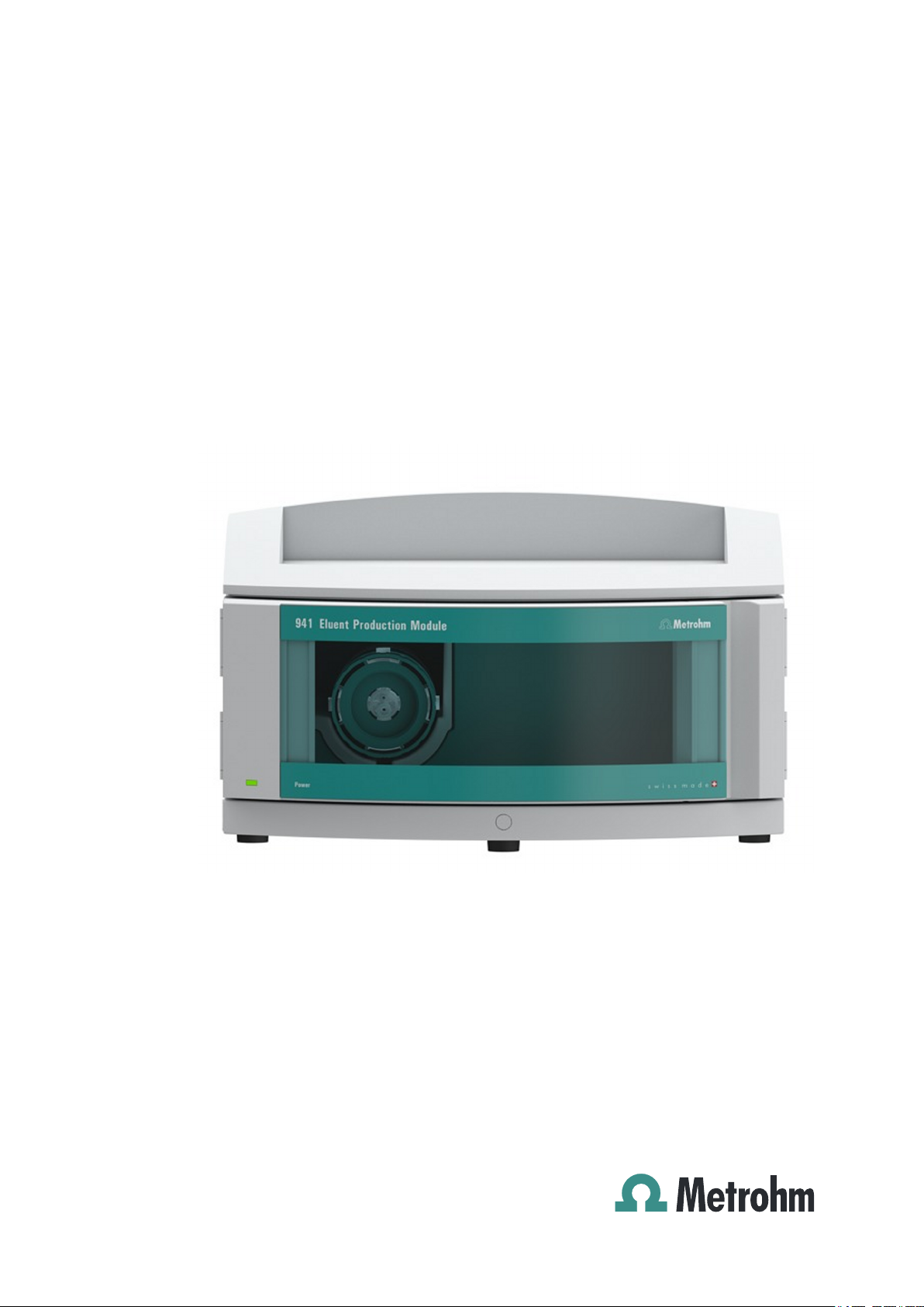
941 Eluent Production Module
Manual
8.941.8001EN
Page 2

Page 3

Metrohm AG
CH-9100 Herisau
Switzerland
Phone +41 71 353 85 85
Fax +41 71 353 89 01
info@metrohm.com
www.metrohm.com
941 Eluent Production Module
8.941.8001EN
Manual
09.2013 zst
Page 4

Teachware
Metrohm AG
CH-9100 Herisau
teachware@metrohm.com
This documentation is protected by copyright. All rights reserved.
Although all the information given in this documentation has been
checked with great care, errors cannot be entirely excluded. Should you
notice any mistakes please send us your comments using the address
given above.
Documentation in additional languages can be found on
http://documents.metrohm.com.
Page 5

■■■■■■■■■■■■■■■■■■■■■■
Table of contents
1 Introduction 1
1.1 Instrument description ......................................................... 1
1.1.1 Intended use ........................................................................... 1
1.2 About the documentation ................................................... 2
1.2.1 Symbols and conventions ........................................................ 2
1.3 Safety instructions ................................................................ 3
1.3.1 General notes on safety ........................................................... 3
1.3.2 Electrical safety ........................................................................ 3
1.3.3 Tubing and capillary connections ............................................. 4
1.3.4 Flammable solvents and chemicals ........................................... 4
1.3.5 Recycling and disposal ............................................................. 4
2 Overview of the instrument 6
2.1 Front ...................................................................................... 6
Table of contents
2.2 Rear ........................................................................................ 7
3 System overview 8
4 Installation 10
4.1 Setting up the instrument .................................................. 10
4.1.1 Packaging .............................................................................. 10
4.1.2 Checks .................................................................................. 10
4.1.3 Location ................................................................................ 10
4.2 Base tray and bottle holder ............................................... 10
4.2.1 Basic information on base tray and bottle holder ................... 10
4.2.2 Mounting base tray and bottle holder (optional) .................... 11
4.3 Connecting the eluent bottle ............................................. 16
4.4 Connecting the concentrate bottle ................................... 19
4.5 Connecting the ultrapure water container ....................... 22
4.5.1 Connecting the ultrapure water canister ................................ 22
4.5.2 Connecting an ELGA PURELAB flex ........................................ 25
4.6 Installing the Dosino .......................................................... 26
4.7 Connecting the instrument ................................................ 29
4.7.1 Connecting the instrument to the ion chromatograph ........... 29
4.7.2 Connecting the instrument to the power supply .................... 29
5 Operation 31
6 Operation and maintenance 32
6.1 Care ...................................................................................... 32
941 Eluent Production Module (2.941.0010)
■■■■■■■■
III
Page 6

Table of contents
■■■■■■■■■■■■■■■■■■■■■■
6.2 Servicing the door .............................................................. 32
6.3 Dosino .................................................................................. 33
6.4 Dosing unit .......................................................................... 33
6.5 Quality Management and qualification with
Metrohm ............................................................................. 33
7 Troubleshooting 35
7.1 Dosino .................................................................................. 35
7.2 Dosing unit .......................................................................... 35
8 Technical specifications 36
8.1 Reference conditions .......................................................... 36
8.2 Ambient temperature ......................................................... 36
8.3 Level sensor ........................................................................ 36
8.4 Housing ............................................................................... 37
8.5 Dosino .................................................................................. 37
8.6 Dosing unit .......................................................................... 37
8.7 Power connection ............................................................... 37
8.8 Interfaces ............................................................................. 38
8.9 Safety specifications ........................................................... 38
8.10 Electromagnetic compatibility (EMC) ................................ 38
9 Warranty (guarantee) 40
10 Accessories 42
Index 44
■■■■■■■■
IV
941 Eluent Production Module (2.941.0010)
Page 7

■■■■■■■■■■■■■■■■■■■■■■
Table of figures
Figure 1 Front ................................................................................................. 6
Figure 2 Rear .................................................................................................. 7
Figure 3 Bottle cap for level sensor - Inserting the measuring sensor ............. 16
Figure 4 Installing the eluent bottle cap with level sensor .............................. 17
Figure 5 Installing the concentrate bottle cap without level sensor ................ 19
Figure 6 Installing the concentrate bottle cap with level sensor ..................... 20
Figure 7 Installing the ultrapure water canister cap without level sensor ........ 22
Figure 8 Installing the ultrapure water canister cap with level sensor ............. 23
Figure 9 Installing an ELGA PURELAB flex ...................................................... 25
Figure 10 Connecting the Dosino .................................................................... 27
Table of figures
941 Eluent Production Module (2.941.0010)
■■■■■■■■
V
Page 8

Page 9

■■■■■■■■■■■■■■■■■■■■■■
1 Introduction
1.1 Instrument description
The 941 Eluent Production Module allows you to produce eluent for
your IC system from a concentrate and ultrapure water as needed and in a
software-controlled manner.
Thanks to the built-in Level Control, the instrument is capable of monitoring the liquid levels in up to four liquid containers, if they are equipped
with level sensors.
A level sensor for the eluent bottle is indispensable for the automated production of eluent and is contained in the scope of delivery of the 941 Eluent Production Module. However, we recommend using level sensors to
also monitor the bottle with the concentrate and the ultrapure water container. Additional level sensors are available as optional accessories in various versions.
1 Introduction
The 941 Eluent Production Module is operated with the MagIC Net software. If the 941 Eluent Production Module is connected to a 940 Professional IC Vario instrument, MagIC Net automatically detects the 941 Eluent Production Module and checks its functional capability. It controls and
monitors the entire IC system including all connected instruments; it evaluates the measured data and manages it in a database.
1.1.1 Intended use
The 941 Eluent Production Module is an instrument for the automated
production of eluent for ion chromatography systems. It can monitor the
levels of various liquid containers and, where necessary, perform appropriate actions controlled by the software.
The present instrument is suitable for processing chemicals. Usage of the
941 Eluent Production Module therefore requires the user to have basic
knowledge and experience in handling toxic and caustic substances.
Knowledge with respect to the application of the fire prevention measures
prescribed for laboratories is also mandatory.
941 Eluent Production Module (2.941.0010)
■■■■■■■■
1
Page 10
1.2 About the documentation
1.2 About the documentation
CAUTION
Please read through this documentation carefully before putting the
instrument into operation. The documentation contains information
and warnings which the user must follow in order to ensure safe operation of the instrument.
1.2.1 Symbols and conventions
The following symbols and formatting may appear in this documentation:
Cross-reference to figure legend
The first number refers to the figure number, the second to the instrument part in the figure.
■■■■■■■■■■■■■■■■■■■■■■
Instruction step
Carry out these steps in the sequence shown.
Method Dialog text, parameter in the software
File ▶ New Menu or menu item
[Next] Button or key
WARNING
This symbol draws attention to a possible life-threatening hazard or risk of injury.
WARNING
This symbol draws attention to a possible hazard due
to electrical current.
WARNING
This symbol draws attention to a possible hazard due
to heat or hot instrument parts.
WARNING
This symbol draws attention to a possible biological
hazard.
■■■■■■■■
2
CAUTION
This symbol draws attention to possible damage to
instruments or instrument parts.
941 Eluent Production Module (2.941.0010)
Page 11
■■■■■■■■■■■■■■■■■■■■■■
1.3 Safety instructions
1.3.1 General notes on safety
WARNING
This instrument may only be operated in accordance with the specifications in this documentation.
This instrument has left the factory in a flawless state in terms of technical
safety. To maintain this state and ensure non-hazardous operation of the
instrument, the following instructions must be observed carefully.
1.3.2 Electrical safety
The electrical safety when working with the instrument is ensured as part
of the international standard IEC 61010.
1 Introduction
NOTE
This symbol highlights additional information and
tips.
WARNING
Only personnel qualified by Metrohm are authorized to carry out service
work on electronic components.
WARNING
Never open the housing of the instrument. The instrument could be
damaged by this. There is also a risk of serious injury if live components
are touched.
There are no parts inside the housing which can be serviced or replaced
by the user.
Mains voltage
WARNING
An incorrect mains voltage can damage the instrument.
Only operate this instrument with a mains voltage specified for it (see
rear panel of the instrument).
941 Eluent Production Module (2.941.0010)
■■■■■■■■
3
Page 12
1.3 Safety instructions
Protection against electrostatic charges
WARNING
Electronic components are sensitive to electrostatic charges and can be
destroyed by discharges.
Do not fail to pull the mains cable out of the mains connection socket
before you set up or disconnect electrical plug connections at the rear
of the instrument.
1.3.3 Tubing and capillary connections
CAUTION
Leaks in tubing and capillary connections are a safety risk. Tighten all
connections well by hand. Avoid applying excessive force to tubing
connections. Damaged tubing ends lead to leakage. Appropriate tools
can be used to loosen connections.
■■■■■■■■■■■■■■■■■■■■■■
Check the connections regularly for leakage. If the instrument is used
mainly in unattended operation, then weekly inspections are mandatory.
1.3.4 Flammable solvents and chemicals
WARNING
All relevant safety measures are to be observed when working with
flammable solvents and chemicals.
■ Set up the instrument in a well-ventilated location (e.g. fume cup-
board).
■ Keep all sources of flame far from the workplace.
■ Clean up spilled liquids and solids immediately.
■ Follow the safety instructions of the chemical manufacturer.
1.3.5 Recycling and disposal
This product is covered by European Directive 2002/96/EC, WEEE – Waste
from Electrical and Electronic Equipment.
■■■■■■■■
4
The correct disposal of your old equipment will help to prevent negative
effects on the environment and public health.
941 Eluent Production Module (2.941.0010)
Page 13

■■■■■■■■■■■■■■■■■■■■■■
1 Introduction
More details about the disposal of your old equipment can be obtained
from your local authorities, from waste disposal companies or from your
local dealer.
941 Eluent Production Module (2.941.0010)
■■■■■■■■
5
Page 14
2.1 Front
2 Overview of the instrument
2.1 Front
■■■■■■■■■■■■■■■■■■■■■■
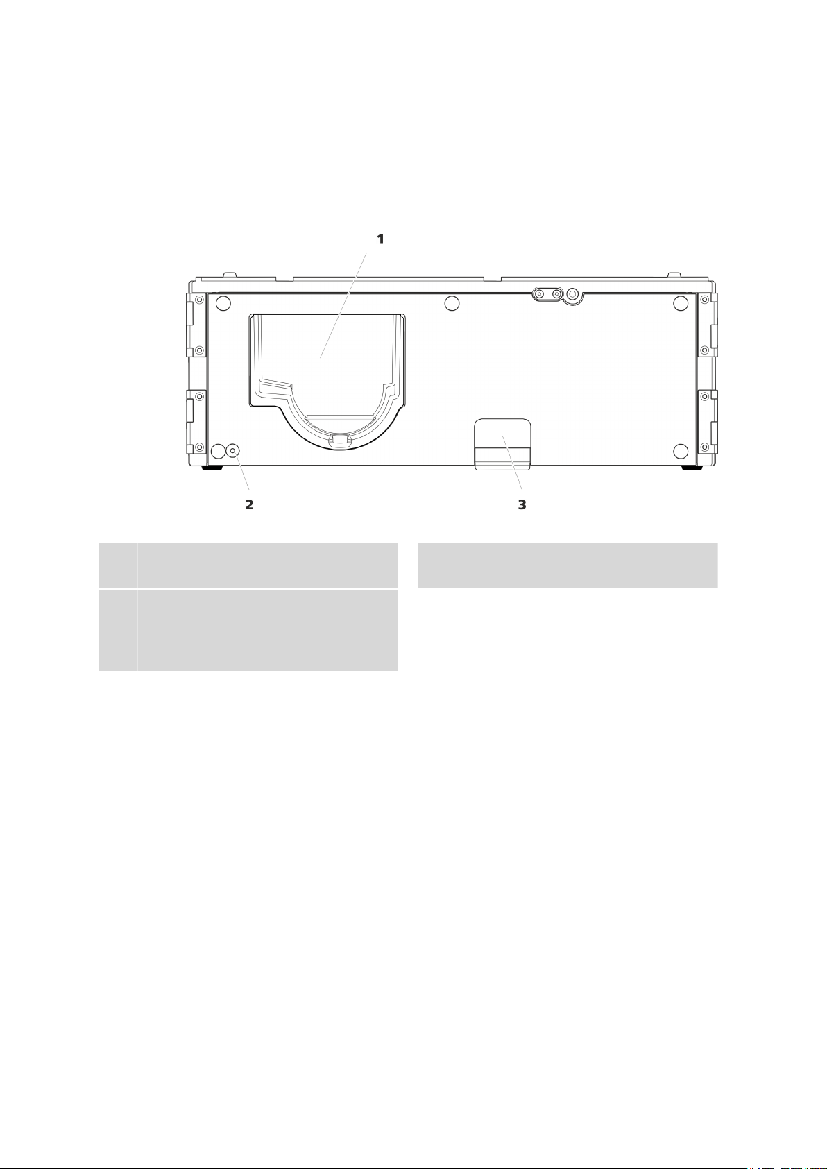
Figure 1 Front
Dosino holder
1
Receptacle for a Dosino.
Cable conduit
3
Conduit to the rear of the instrument. For
feeding through tubing and the Dosino
cable.
LED
2
Standby indicator.
■■■■■■■■
6
941 Eluent Production Module (2.941.0010)
Page 15
■■■■■■■■■■■■■■■■■■■■■■
2.2 Rear
2 Overview of the instrument
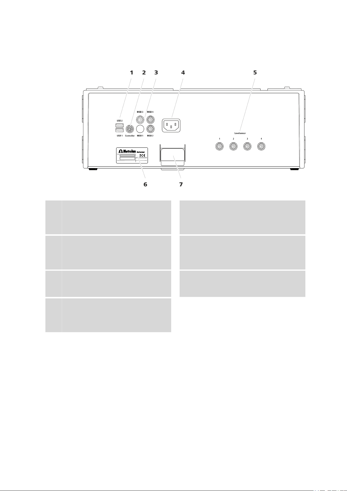
Figure 2 Rear
USB sockets
1
Two sockets for plugging in USB cables for
connecting devices with USB connector.
Labeled USB 1 and USB 2.
MSB sockets
3
Three sockets for plugging in MSB cables for
connecting devices with MSB connector.
Labeled MSB 2, MSB 3 and MSB 4.
Level sensor sockets
5
Four sockets for connecting level sensor
cables (6.2151.060).
Cable conduit
7
Conduit to the front of the instrument. For
feeding through tubing and the Dosino
cable.
Controller socket
2
Socket for plugging in the USB cable
(6.2151.000) for connecting the ion chromatograph.
Power socket
4
For connecting the power supply cable.
Type plate
6
941 Eluent Production Module (2.941.0010)
■■■■■■■■
7
Page 16
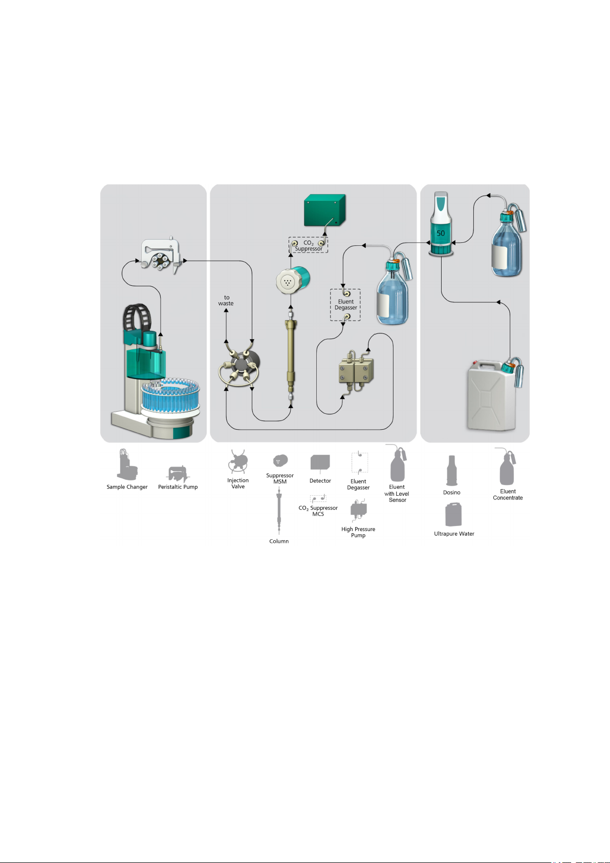
3 System overview
The following figure shows an ion chromatography system with a Sample
Processor (left), the ion chromatograph (middle) and the 941 Eluent Production Module (right).
■■■■■■■■■■■■■■■■■■■■■■
■■■■■■■■
8
The 941 Eluent Production Module consists of a housing with a built-in
Level Control. A Dosino with a 50 mL dosing unit, the canister for ultrapure water, the bottle for the eluent concentrate, the level sensor for the
eluent bottle and all small parts required for a standard setup are included
in the accessories supplied.
In a standard setup, only the eluent bottle is equipped with a level sensor.
The ultrapure water canister and the bottle with the concentrate are not
monitored.
If you intend to let your ion chromatography system run unsupervised for
extended periods of time, we recommend also monitoring the concentrate bottle and the ultrapure water canister with a level sensor.
941 Eluent Production Module (2.941.0010)
Page 17

■■■■■■■■■■■■■■■■■■■■■■
3 System overview
Level sensors come with measuring sensors in different lengths:
■ Sensors with short measuring sensors warn when the liquid container
is full (FULL sensor).
■ Sensors with long measuring sensors warn when the liquid container is
empty (EMPTY sensor). Sensors with measuring sensors of different
lengths are available for 1 L bottles, 2 L bottles and for 10 L canisters.
941 Eluent Production Module (2.941.0010)
■■■■■■■■
9
Page 18

4.1 Setting up the instrument
4 Installation
4.1 Setting up the instrument
4.1.1 Packaging
The instrument is supplied in highly protective special packaging together
with the separately packed accessories. Keep this packaging, as only this
ensures safe transportation of the instrument.
4.1.2 Checks
Immediately after receipt, check whether the shipment has arrived complete and without damage by comparing it with the delivery note.
4.1.3 Location
The 941 Eluent Production Module can be placed directly onto the 940
Professional IC Vario. To accomplish this, the bottle holder of the ion chromatograph has to be removed and placed onto the 941 Eluent Production
Module (see Chapter 4.2.2.2, page 13).
■■■■■■■■■■■■■■■■■■■■■■
The 941 Eluent Production Module can also be placed directly under the
940 Professional IC Vario. To accomplish this, the base tray of the ion
chromatograph has to be removed and installed again under the 941 Eluent Production Module (see Chapter 4.2.2.1, page 11).
As an alternative, the 941 Eluent Production Module can be set up
together with other instruments with the same footprint in a separate
stack next to the ion chromatograph. We recommend that a bottle holder
(6.2061.100) and a base tray (6.2061.110) be installed for each stack of
instruments.
4.2 Base tray and bottle holder
4.2.1 Basic information on base tray and bottle holder
The base tray (6.2061.110) and bottle holder (6.2061.100) protect IC
instruments from dust, dirt and leaking fluids. The supply bottles for eluent
and auxiliary solutions can be positioned neatly on the bottle holder.
In a complex IC system, several different instruments may be used, such as
an analyzer, an extension module and a detector. These instruments can
be set up in one or more stacks. We recommend that a base tray and bottle holder be mounted for each stack of IC instruments.
■■■■■■■■
10
941 Eluent Production Module (2.941.0010)
Page 19

■■■■■■■■■■■■■■■■■■■■■■
The bottle holder and base tray must be removed or set up every time one
of the following instruments is to be mounted on or under a 940 Professional IC Vario:
■ One or more 942 Extension Module Vario.
■ Or another instrument with the same-sized footprint.
4.2.2 Mounting base tray and bottle holder (optional)
The base tray and bottle holder come fully assembled on a new ion chromatograph. If you wished to install an extension module on the ion chromatograph, you would have to remove the bottle holder and put it back
on top of the topmost instrument. If you wished to install an extension
module below the ion chromatograph, you would have to remove the
base tray and set it under the lowest instrument.
4 Installation
4.2.2.1
Removing/mounting the base tray
The base tray must be removed if you want to install another instrument
under the IC instrument.
CAUTION
Do not allow capillaries or leak sensor cables to be pinched!
Pinches in the leak sensor cable or the capillaries fed through the guide
ducts between the base tray and the instrument may lead to malfunctions.
Unplug the leak sensor cable. Remove all of the capillaries from the
capillary ducts.
Removing the base tray
Before you can remove the base tray, the following preconditions must be
met:
■ The instrument is switched off.
■ The bottle holder is cleared.
■ All of the cable connections on the rear have been disconnected.
■ The capillaries are removed from the guide ducts between the instru-
ment and the base tray.
■ There are no loose parts in the instrument.
To remove the base tray, you need a 3 mm hex key (6.2621.100).
941 Eluent Production Module (2.941.0010)
■■■■■■■■
11
Page 20

4.2 Base tray and bottle holder
1
2
3
■■■■■■■■■■■■■■■■■■■■■■
Tilt the instrument sideways and lay it down flat.
1
Loosen the four cylinder screws with the 3 mm hex key and remove
2
them and their washers.
Remove the base tray.
3
The base tray must always be mounted under the lowermost instrument
of the stack.
Mounting the base tray
Before you can mount the base tray, the following preconditions must be
met:
■ The instrument is switched off.
■ The bottle holder is cleared.
■ All of the cable connections on the rear have been disconnected.
■ There are no loose parts in the instrument.
■ The instrument is lying on its side, and the bottom surface is visible.
To mount the base tray, you need a 3 mm hex key (6.2621.100).
■■■■■■■■
12
941 Eluent Production Module (2.941.0010)
Page 21

■■■■■■■■■■■■■■■■■■■■■■
1
3
2
Place the base tray in such a way that the openings in the base tray
1
match exactly the screw threads in the bottom of the instrument.
Slide the washers onto the cylinder screws, insert the screws and
2
tighten them with the 3 mm hex key.
Set the instrument back up on the base tray.
3
4 Installation
4.2.2.2
Stack other instruments in the required order. Mount the bottle holder
(6.2061.100) onto the topmost instrument on the stack (see "Mounting
the bottle holder", page 15).
Removing/mounting the bottle holder
The bottle holder must be removed if you want to install another instrument onto the IC instrument.
Removing the bottle holder
Before you can remove the bottle holder, the following preconditions
must be met:
■ The instrument is switched off.
■ The bottle holder is cleared.
■ Drainage tubing is disconnected from the drainage tubing connection
of the bottle holder.
■ The capillaries are removed from the guide ducts between the instru-
ment and the bottle holder.
To remove the bottle holder, you need a 3 mm hex key (6.2621.100).
941 Eluent Production Module (2.941.0010)
■■■■■■■■
13
Page 22

4.2 Base tray and bottle holder
1
2 3
■■■■■■■■■■■■■■■■■■■■■■
Remove the two covering stoppers.
1
Loosen the two cylinder screws with the 3 mm hex key and remove
2
them.
Remove the bottle holder.
3
Stack other instruments in the required order. Mount the bottle holder
(6.2061.100) onto the topmost instrument on the stack.
■■■■■■■■
14
941 Eluent Production Module (2.941.0010)
Page 23

■■■■■■■■■■■■■■■■■■■■■■
1
2 3
4 Installation
Mounting the bottle holder
Before you can mount the bottle holder, the following preconditions must
be met:
■ The instrument is switched off.
To mount the bottle holder, you need a 3 mm hex key (6.2621.100).
Place the bottle holder onto the topmost instrument in such a way
1
that the openings in the bottle holder exactly match the screw
threads on the top surface of the instrument.
Insert the two cylinder screws and tighten them with the 3 mm hex
2
key.
Insert both covering stoppers.
3
After attaching the bottle holder, all connections that were undone at the
beginning of the process must be reconnected.
Restoring the loosened connections
Plug in all necessary USB cables.
1
Plug in all necessary MSB cables.
2
Plug in the power supply cable.
3
Mount the drainage tubing again (see manual of the IC instrument).
4
941 Eluent Production Module (2.941.0010)
■■■■■■■■
15
Page 24

4.3 Connecting the eluent bottle
A longer section of silicone tubing (6.1816.020) may have to be cut
to size and mounted (see also the manual for the IC instrument).
If one of the instruments in the stack is equipped with a leak sensor
5
connection socket, connect the leak sensor (see manual of the IC
instrument).
Restore any capillary connections that may have been removed.
6
4.3 Connecting the eluent bottle
For the automated eluent production, the eluent bottle must be equipped
with a bottle cap for a level sensor and a sensor of the type "FULL".
Inserting the measuring sensor
Accessories
For this step you need:
■ A bottle cap for level sensor (6.1626.000)
■ FULL sensor (6.2769.000) for anion eluents or EMPTY sensor
(6.2769.1X0) for cation eluents
■■■■■■■■■■■■■■■■■■■■■■
■■■■■■■■
16
Figure 3 Bottle cap for level sensor - Inserting the measuring sensor
Measuring sensor opening
1
For two measuring sensors (inside) and the
level sensor cable (outside).
Adsorber opening
3
Remove the stoppers from the bottle cap.
1
Place the bottle cap on a surface with the opening facing up.
2
M6 opening
2
For the FEP tubing connection to the Dosino.
M8 opening
4
For the capillary connection to the ion chromatograph.
941 Eluent Production Module (2.941.0010)
Page 25

■■■■■■■■■■■■■■■■■■■■■■
Insert the two measuring sensors from the inside into the two open-
3
ings for measuring sensors.
Assembling the bottle cap
Accessories For this step you need:
■ Eluent bottle (6.1608.070) from the accessories set of the ion chroma-
tograph.
■ Bottle cap for level sensor (6.1626.000) with inserted measuring sen-
sors (see "Inserting the measuring sensor", page 16).
■ FEP aspiration tubing (6.1819.100)
■ FEP tubing (6.1805.530)
■ Level sensor cable (6.2151.060)
■ Adsorber tube (6.1619.000)
■ Spiral band (6.1815.010)
4 Installation
Figure 4
1
Connecting the FEP tubing
Fasten the tubing connection to the Dosino to the M6 opening.
■ Insert the FEP aspiration tubing into the M6 opening.
■ Screw the FEP tubing into the M6 opening.
941 Eluent Production Module (2.941.0010)
Installing the eluent bottle cap with level sensor
■■■■■■■■
17
Page 26

4.3 Connecting the eluent bottle
■■■■■■■■■■■■■■■■■■■■■■
2
Connecting the eluent aspiration tubing
Fasten the capillary connection to the ion chromatograph to the M8
opening.
■ Start by pushing the M8 tubing nipple over the end of the aspira-
tion tubing, followed by the O-ring.
■ Temporarily secure the eluent aspiration tubing in the M8 open-
ing.
■ Attach the tubing weighting and the aspiration filter to the end of
the eluent aspiration tubing, see the manual of the ion chromatograph.
3
Connecting the level sensor cable
Connect the two plugs of the level sensor cable to the two sockets.
4
Mounting the adsorber
Fill the adsorber tube with adsorber material and cotton and insert it
into the last remaining opening.
5
Bundling the level sensor cables and tubings
NOTE
The fine connection cables of the level sensor cable break off easily
if the bottle cap is rotated too much.
The level sensor cable is damaged as a result and needs to be
replaced.
To prevent the connection cables from breaking off, we recommend bundling the level sensor cable together with the tubings
and capillaries that are connected to the bottle cap.
Tie the level sensor cable, the FEP tubing and the eluent aspiration
tubing together using a spiral band. Tie a piece of spiral band with a
length of approx. 10 cm around the cable and the tubings as close as
possible to the bottle cap.
6
Attaching the bottle cap
Screw the bottle cap to the eluent bottle and install the eluent bottle
on the bottle holder of the ion chromatograph.
■■■■■■■■
18
941 Eluent Production Module (2.941.0010)
Page 27

■■■■■■■■■■■■■■■■■■■■■■
4.4 Connecting the concentrate bottle
The bottle with the concentrate can be equipped with a bottle cap without level sensor, e.g. with the bottle cap (6.1602.160).
Accessories For this step you need the following accessories:
■ Bottle (6.1608.070) filled with concentrate
■ Bottle cap (6.1602.160)
■ FEP aspiration tubing (6.1819.100)
■ FEP tubing (6.1805.530)
■ Adsorber tube (6.1609.000)
■ SGJ clip for SGJ 14/15 (6.2023.020)
4 Installation
Figure 5 Installing the concentrate bottle cap without level sensor
1
Connecting the FEP tubing
Fasten the tubing connection to the Dosino to the M6 opening.
■ Insert the FEP aspiration tubing into the M6 opening.
■ Screw the FEP tubing into the M6 opening.
2
Sealing the M8 opening
Screw the M8 threaded stopper into the M8 opening.
3
Mounting the adsorber
Fill the adsorber tube with adsorber material and cotton (for anion
eluents) or only with cotton (for cation eluents) and insert it into the
large opening. Secure in place with an SGJ clip.
941 Eluent Production Module (2.941.0010)
■■■■■■■■
19
Page 28

4.4 Connecting the concentrate bottle
■■■■■■■■■■■■■■■■■■■■■■
Recommendation If you intend to let your ion chromatography system run unsupervised for
extended periods of time, we recommend also monitoring the level of the
concentrate bottle with a level sensor.
For this purpose, you need to order the following optional accessories:
■ Bottle cap for level sensor (6.1626.000) incl. adsorber tube
(6.1619.000)
■ EMPTY sensor (6.2769.110 for 2 L bottle or 6.2769.100 for 1 L bottle
or 6.2769.120 for 10 L canister)
■ Level sensor cable (6.2151.060)
■ FEP tubing (6.1805.530), is contained in the accessories of the 941 Elu-
ent Production Module.
■■■■■■■■
20
Figure 6
1
Installing the concentrate bottle cap with level sensor
Inserting the measuring sensor
Insert the two measuring sensors from the inside into the two openings for measuring sensors.
2
Connecting the FEP tubing
Fasten the tubing connection to the Dosino to the M6 opening.
■ Insert the FEP aspiration tubing (6.1819.100) into the M6 open-
ing.
■ Screw the FEP tubing into the M6 opening.
941 Eluent Production Module (2.941.0010)
Page 29

■■■■■■■■■■■■■■■■■■■■■■
4 Installation
3
Sealing the M8 opening
Screw the M8 threaded stopper into the M8 opening.
4
Connecting the level sensor cable
Connect the two plugs of the level sensor cable to the two sockets.
5
Mounting the adsorber
Fill the adsorber tube with cotton and insert it into the last remaining
opening.
6
Bundling the level sensor cables and tubings
NOTE
The fine connection cables of the level sensor cable break off easily
if the bottle cap is rotated too much.
The level sensor cable is damaged as a result and needs to be
replaced.
To prevent the connection cables from breaking off, we recommend bundling the level sensor cable together with the tubings
and capillaries that are connected to the bottle cap.
Tie the level sensor cable and the FEP tubing together using a spiral
band. Tie a piece of spiral band with a length of approx. 10 cm
around the cable and the tubings as close as possible to the bottle
cap.
7
Attaching the bottle cap
Screw the bottle cap onto the concentrate bottle.
941 Eluent Production Module (2.941.0010)
■■■■■■■■
21
Page 30

4.5 Connecting the ultrapure water container
■■■■■■■■■■■■■■■■■■■■■■
4.5 Connecting the ultrapure water container
The ultrapure water can be aspirated either from a 10 L canister or an
ELGA PURELAB water purification system.
The 10 L canister is included in the scope of delivery and is used for the
standard installation.
4.5.1 Connecting the ultrapure water canister
Assembling the bottle cap without level sensor
The canister with the ultrapure water can be equipped with a bottle cap
without level sensor, e.g. with the bottle cap (6.1602.160).
Accessories
For this step you need the following accessories:
■ Canister, 10 L (6.1621.000)
■ Bottle cap (6.1602.160)
■ FEP aspiration tubing (6.1819.100)
■ FEP tubing (6.1805.530)
■ Adsorber tube (6.1609.000 + 6.1624.000)
■■■■■■■■
22
Figure 7 Installing the ultrapure water canister cap without level sen-
sor
1
Connecting the FEP tubing
Fasten the tubing connection to the Dosino to the M6 opening.
■ Insert the FEP aspiration tubing into the M6 opening.
■ Screw the FEP tubing into the M6 opening.
941 Eluent Production Module (2.941.0010)
Page 31

■■■■■■■■■■■■■■■■■■■■■■
4 Installation
2
Sealing the M8 opening
Screw the M8 threaded stopper into the M8 opening.
3
Mounting the adsorber
Fill the adsorber tube with soda lime and cotton and insert it into the
large opening. Secure in place with an SGJ clip.
Option: Assembling the bottle cap with level sensor
If you intend to let your ion chromatography system run unsupervised for
extended periods of time, we recommend also monitoring the ultrapure
water canister with a level sensor.
Accessories
For this step you need the following optional accessories:
■ A bottle cap for level sensor (6.1626.000)
■ EMPTY sensor for 10 L canister (6.2769.120)
Figure 8 Installing the ultrapure water canister cap with level sensor
1
Inserting the measuring sensor
Insert the two measuring sensors from the inside into the two openings for measuring sensors.
941 Eluent Production Module (2.941.0010)
■■■■■■■■
23
Page 32

4.5 Connecting the ultrapure water container
2
Connecting the FEP tubing
Fasten the tubing connection to the Dosino to the M6 opening.
■ Insert the FEP aspiration tubing (6.1819.110) into the M6 open-
■ Screw the FEP tubing into the M6 opening.
3
Sealing the M8 opening
Seal the M8 opening with a stopper.
4
Connecting the level sensor cable
Connect the two plugs of the level sensor cable to the two sockets.
5
Mounting the adsorber
Fill the adsorber tube with soda lime and cotton and insert it with the
adapter into the last remaining opening.
6
Bundling the level sensor cables and tubings
■■■■■■■■■■■■■■■■■■■■■■
ing.
NOTE
The fine connection cables of the level sensor cable break off easily
if the bottle cap is rotated too much.
The level sensor cable is damaged as a result and needs to be
replaced.
To prevent the connection cables from breaking off, we recommend bundling the level sensor cable together with the tubings
and capillaries that are connected to the bottle cap.
Tie the level sensor cable and the FEP tubing together using a spiral
band. Tie a piece of spiral band with a length of approx. 10 cm
around the cable and the tubings as close as possible to the bottle
cap.
7
Attaching the bottle cap
Screw the bottle cap onto the canister.
■■■■■■■■
24
941 Eluent Production Module (2.941.0010)
Page 33

■■■■■■■■■■■■■■■■■■■■■■
4.5.2 Connecting an ELGA PURELAB flex
The 941 Eluent Production Module can also be connected directly to an
ELGA PURELAB flex water purification system, as an alternative to the
ultrapure water canister.
The ELGA PURELAB flex is not included in the scope of delivery and has to
be ordered separately.
An ultrapure water insert specifically for Metrohm applications is included
in the ELGA PURELAB flex. This insert ensures that ultrapure water is aspirated at all times and has two connectors, each for one piece of FEP tubing.
This ultrapure water insert must be put in place during installation.
4 Installation
Accessories
Composite aeration filter
1
For this step you need the following accessories:
■ ELGA PURELAB flex, incl. ultrapure water insert
■ FEP tubing (6.1805.530)
Figure 9 Installing an ELGA PURELAB flex
Ultrapure water insert
2
941 Eluent Production Module (2.941.0010)
■■■■■■■■
25
Page 34

4.6 Installing the Dosino
■■■■■■■■■■■■■■■■■■■■■■
Installing an ELGA PURELAB flex
Install the ELGA PURELAB flex as described in the manufacturer's documentation.
Carry out the following steps before installing the composite aeration filter.
1
Installing the ultrapure water insert
Screw the ultrapure water insert supplied in the opening in which the
composite aeration filter is to be installed according to the manufacturer's documentation.
2
Inserting the composite aeration filter
Screw the composite aeration filter onto the ultrapure water insert.
3
Connecting the FEP tubing
Screw the FEP tubing onto one of the connectors of the ultrapure
water insert.
4.6 Installing the Dosino
Attaching the Dosino to the Dosing Unit
Accessories
Accessories
For this step you need the following accessories:
■ 800 Dosino (2.800.0010)
■ Dosing Unit 50 mL (6.3032.250)
The manual for the 800 Dosino describes how to attach the 800 Dosino
correctly to a dosing unit.
CAUTION
Please read through the correct procedure in the manual for the 800
Dosino before you attach the Dosino to the dosing unit.
Installing FEP tubings
For this step you need the following accessories:
■ 800 Dosino (2.800.0010) with dosing unit 50 mL (6.3032.250)
attached
■ The three FEP tubings connected to the bottles,
one additional FEP tubing (6.1805.530)
■■■■■■■■
26
941 Eluent Production Module (2.941.0010)
Page 35

■■■■■■■■■■■■■■■■■■■■■■
4 Installation
■ Adapter Dosino port 4 (6.1808.280)
Figure 10 Connecting the Dosino
Port 1
1
For connecting the concentrate bottle.
Port 3
3
For connecting the eluent bottle.
1
2
Port 2
2
For connecting the ultrapure water supply.
Port 4
4
For connecting the waste container.
Connecting the concentrate bottle
■ Push the FEP tubing attached to the concentrate bottle through
the cable conduit from the rear to the front of the 941 Eluent Production Module.
■ Screw the FEP tubing onto Port 1 of the Dosino.
Connecting the ultrapure water
■ Push the FEP tubing connected to the ultrapure water canister or
the ELGA PURELAB flex through the cable conduit from the rear
to the front of the 941 Eluent Production Module.
■ Screw the FEP tubing onto port 2 of the Dosino.
941 Eluent Production Module (2.941.0010)
■■■■■■■■
27
Page 36

4.6 Installing the Dosino
■■■■■■■■■■■■■■■■■■■■■■
3
Connecting the eluent bottle
■ Push the FEP tubing attached to the eluent bottle through the
cable conduit from the rear to the front of the 941 Eluent Production Module.
■ Screw the FEP tubing onto port 3 of the Dosino.
4
Connecting the waste container
■ Attach the adapter to port 4 of the Dosino and screw the fourth
FEP tubing onto the adapter.
■ Guide the other end of the FEP tubing from the front through the
cable conduit to the rear of the 941 Eluent Production Module
and attach to the waste container.
Inserting the Dosino into the instrument
Insert the Dosino sideways into the Dosino holder.
1
The cable has to rest on the left side in the recess designated for this
purpose.
Guide the Dosino cable through the cable conduit to the rear of the
2
instrument.
Plug the Dosino cable into one of the MSB sockets.
3
■■■■■■■■
28
941 Eluent Production Module (2.941.0010)
Page 37

■■■■■■■■■■■■■■■■■■■■■■
4.7 Connecting the instrument
4.7.1 Connecting the instrument to the ion chromatograph
NOTE
The 940 Professional IC Vario must be switched off when connecting
the 941 Eluent Production Module!
Accessories For this step you need the following accessories:
■ Controller cable (6.2151.000)
Insert the Mini DIN plug of the controller cable into the connection
1
socket on the rear of the instrument labeled Controller.
Insert the USB A plug of the controller cable into a USB socket of the
2
ion chromatograph.
4 Installation
4.7.2 Connecting the instrument to the power supply
WARNING
The power supply unit must not get wet. Protect it from liquids.
The power supply cable is three-core and provided with a plug with
grounding. If another plug has to be mounted, the yellow/green conductor (IEC standard) must be connected to the protective ground (protection
class I).
Accessories
For this step you need the following accessories:
■ For Switzerland, …: Power supply cable with IEC 60320 line socket,
type C13, with SEV 1011 plug, type 12 (6.2122.020), 1.5 m
■ For Germany, …: Power supply cable with IEC 60320 line socket, type
C13, with CEE 7 plug, type VII (6.2122.040), 1.5 m
■ For the USA, …: Power supply cable with IEC 60320 line socket, type
C13, with NEMA 5-15 plug, type 498 (6.2122.070), 1.5 m
Connecting the power supply cable
1
Plugging in the power supply cable
■ Plug the power supply cable into the instrument's power socket.
941 Eluent Production Module (2.941.0010)
■■■■■■■■
29
Page 38

4.7 Connecting the instrument
■■■■■■■■■■■■■■■■■■■■■■
■ Connect the power supply cable to the power supply.
■■■■■■■■
30
941 Eluent Production Module (2.941.0010)
Page 39

■■■■■■■■■■■■■■■■■■■■■■
5 Operation
5 Operation
The instrument is operated via MagIC Net software only. Additional information on operating MagIC Net can be found in the document
"MagIC Net Tutorial" or in the software's online help.
941 Eluent Production Module (2.941.0010)
■■■■■■■■
31
Page 40

6.1 Care
6 Operation and maintenance
6.1 Care
WARNING
Untrained personnel may not open the instrument's housing.
The instrument requires appropriate care. Excess contamination of the
instrument may result in malfunctions and a reduction in the lifetime of
the sturdy mechanical and electronic components.
CAUTION
Even though design measures ensure that this will largely be prevented,
the instrument should be switched off without delay in the event that
aggressive media have found their way into the interior of the instrument. This is the only way to prevent extreme damage to the instrument electronics. In such cases, Metrohm Service must be informed.
■■■■■■■■■■■■■■■■■■■■■■
Spilled chemicals and solvents should be removed immediately. In particular, the plug connections should be protected from contamination.
6.2 Servicing the door
CAUTION
The door is made of PMMA (poly(methyl methacrylate)). It must never
be cleaned with abrasive media or solvents.
CAUTION
Never hold the instrument by the door when lifting it. Only hold the
instrument by the housing.
■■■■■■■■
32
941 Eluent Production Module (2.941.0010)
Page 41

■■■■■■■■■■■■■■■■■■■■■■
6.3 Dosino
Information regarding operation and maintenance of the Dosino can be
found in the manual for the 800 Dosino.
Please read the chapter "Operation and maintenance" in the manual for
the 800 Dosino and follow the instructions described in it.
6.4 Dosing unit
Information regarding operation and maintenance of the dosing unit can
be found in the manual for the 807 Dosing Unit.
6 Operation and maintenance
NOTE
NOTE
Please read the chapter "Operation and maintenance" in the manual for
the 807 Dosing Unit and follow the instructions described in it.
6.5 Quality Management and qualification with Metrohm
Quality management
Metrohm offers you comprehensive support in implementing quality management measures for instruments and software. Further information on
this can be found in the brochure "Metrohm Quality Management"
available from your local Metrohm representative.
Qualification
Please contact your local Metrohm representative for support in qualification of instruments and software. The Installation Qualification (IQ)
and Operational Qualification (OQ) are offered by Metrohm representatives as a service. They are carried out by trained employees using standardized qualification documents and in accordance with the currently
applicable requirements of the regulated industry. Further information on
this can be found in the brochure "Analytical Instrument Qualifica-
tion – Confidence in quality with IQ/OQ".
941 Eluent Production Module (2.941.0010)
■■■■■■■■
33
Page 42

6.5 Quality Management and qualification with Metrohm
Maintenance
The electronic and mechanical functional groups of Metrohm instruments
can and should be checked by specialist personnel from Metrohm as part
of a regular preventive maintenance schedule. Please ask your local
Metrohm representative regarding the precise terms and conditions
involved in concluding a corresponding maintenance agreement. Further
information on this can be found in the brochure "Metrohm Care Con-
tracts – Protect your investment the smart way" available from your
local Metrohm representative.
■■■■■■■■■■■■■■■■■■■■■■
■■■■■■■■
34
941 Eluent Production Module (2.941.0010)
Page 43

■■■■■■■■■■■■■■■■■■■■■■
7 Troubleshooting
7.1 Dosino
Information regarding troubleshooting for the Dosino can be found in the
manual for the 800 Dosino.
Please read the "Troubleshooting" chapter in the manual for the 800
Dosino and follow the instructions described in it.
7.2 Dosing unit
Information regarding troubleshooting for the dosing unit can be found in
the manual for the 807 Dosing Unit.
7 Troubleshooting
NOTE
NOTE
Please read the "Troubleshooting" chapter in the manual for the 807
Dosing Unit and follow the instructions described in it.
941 Eluent Production Module (2.941.0010)
■■■■■■■■
35
Page 44

8.1 Reference conditions
8 Technical specifications
8.1 Reference conditions
The technical specifications listed in this chapter refer to the following reference conditions:
■■■■■■■■■■■■■■■■■■■■■■
Ambient temperature
Relative humidity ≦ 60%
Instrument status > 30 minutes in operation
Adjusting interval Annual
+25 °C (± 3 °C)
8.2 Ambient temperature
Automatic interior
temperature monitoring
Nominal function
range
Storage –20 - +60 °C
Transport –40 - +60 °C
+5 - +45 C° at a maximum of 85% humidity
8.3 Level sensor
Measuring inputs
Switching
threshold
Measurement
frequency
■■■■■■■■
36
1 µS
Approx. 1.7 kHz
941 Eluent Production Module (2.941.0010)
Page 45

■■■■■■■■■■■■■■■■■■■■■■
8.4 Housing
Dimensions
Width 365 mm
Height 131 mm
Depth 380 mm
8 Technical specifications
Material of base
tray, housing and
bottle holder
Polyurethane hard foam (PUR) with flame retardation for fire class
UL94V0, CFC-free, coated
8.5 Dosino
You can find the technical specifications for the Dosino in the manual for
the 800 Dosino.
8.6 Dosing unit
You can find the technical specifications for the dosing unit in the manual
for the 807 Dosing Unit.
8.7 Power connection
Required voltage
Required frequency
100 - 240 V ± 10% (autosensing)
50 - 60 Hz ± 3%
Power consumption
Fuse Electronic overload protection
941 Eluent Production Module (2.941.0010)
45 W maximum
■■■■■■■■
37
Page 46

8.8 Interfaces
■■■■■■■■■■■■■■■■■■■■■■
8.8 Interfaces
Controller
Input 1 8-pin Mini DIN socket for a connecting cable to a computer or an ion
chromatograph for controlling the instrument.
USB
Number 2 type A USB sockets for connecting Metrohm instruments or USB
peripheral devices of other manufacturers.
MSB
Number 3 Mini DIN sockets (8-pin) for connecting Dosinos (MSB 1 is used inter-
nally).
Level sensor
Measuring
input
4 Mini DIN sockets (8-pin) for connecting level sensor cables.
8.9 Safety specifications
This instrument fulfills the following electrical safety requirements:
CE marking in accordance with the EU directives:
■ 2006/95/EC (Low Voltage Directive, LVD)
■ 2004/108/EC (EMC Directive, EMC)
Design and testing According to EN/IEC/UL 61010-1, CSA-C22.2 No. 61010-1,
EN/IEC 60529, protection class I, degree of protection IP20.
Safety instructions This document contains safety instructions which have to be followed
by the user in order to ensure safe operation of the instrument.
8.10 Electromagnetic compatibility (EMC)
Emission
Immunity ■ EN/IEC 61326-1
■ EN/IEC 61326-1
■ EN/IEC 61000-6-3
■ EN 55011 / CISPR 11
■ EN/IEC 61000-6-2
■ EN/IEC 61000-4-2
■ EN/IEC 61000-4-3
■ EN/IEC 61000-4-4
■ EN/IEC 61000-4-5
■ EN/IEC 61000-4-6
■ EN/IEC 61000-4-8
■■■■■■■■
38
941 Eluent Production Module (2.941.0010)
Page 47

■■■■■■■■■■■■■■■■■■■■■■
8 Technical specifications
■ EN/IEC 61000-4-11
■ EN/IEC 61000-4-14
■ EN/IEC 61000-4-28
941 Eluent Production Module (2.941.0010)
■■■■■■■■
39
Page 48

9 Warranty (guarantee)
Metrohm guarantees that the deliveries and services it provides are free of
defects in materials, design or manufacturing.
The general warranty period is 36 months (exclusions below) from the
date of delivery, or 18 months in the event of continuous operation. The
warranty remains valid on the condition that the servicing is provided by a
service organization authorized by Metrohm at defined intervals and with
a defined scope.
The warranty period for anion suppressors of the type "MSM" is 120
months from the date of delivery or 60 months in the case of continuous
operation.
The warranty period for IC separation columns is 90 days after start-up.
For third-party components that are recognizable as such, the manufacturer's warranty regulations apply.
■■■■■■■■■■■■■■■■■■■■■■
For instruments sold under the Metrohm NIRSystems brand, a full 16month warranty is applicable. In the event of continuous operation, the
warranty period is reduced by half.
Consumables and materials with limited storage life and glass breakage in
the case of electrodes or other glass parts are excluded from the warranty.
Warranty claims cannot be asserted if the ordering party has failed to
meet its payment obligations according to schedule.
During the warranty period, Metrohm undertakes either to replace free of
charge or to credit the purchaser for any modules or components that can
be shown to be faulty. Any transport or customs fees that may apply are
the responsibility of the ordering party.
The precondition for this is that the ordering party has to specify the article number, the article designation, an adequate error description, the
delivery date and (if applicable) the serial number or chip data in the Support Tracker. Metrohm then decides whether a replacement or a credit
note is to be issued or whether the faulty part has to be returned using
the Return Material Authorization (RMA). If a replacement or credit note is
issued, the ordering party undertakes to store the faulty part for at least
24 months in accordance with the current storage directives (in compliance with ESD guidelines) and to hold it in readiness for onsite inspection
or for return shipment to Metrohm. Metrohm reserves the right to invoice
the ordering party for these articles, including retroactively, in the event of
noncompliance with these preconditions.
■■■■■■■■
40
941 Eluent Production Module (2.941.0010)
Page 49

■■■■■■■■■■■■■■■■■■■■■■
9 Warranty (guarantee)
The same warranty periods that are specified for a corresponding new
part apply to parts that are replaced or repaired within the above-mentioned warranty periods. However, replacement or repair of a part does
not extend the warranty period of the entire system.
Deficiencies arising from circumstances that are not the responsibility of
Metrohm, such as improper storage or improper use, etc., are expressly
excluded from the warranty.
Metrohm also offers a 120-month spare parts availability guarantee and a
60-month PC software support warranty, calculated from the date on
which the product is withdrawn from the market. The content of this warranty is the ability of the customer to obtain functioning spare parts or
appropriate software support at market prices during the time of the warranty period. This does not apply for software products sold under the
Metrohm NIRSystems brand.
If Metrohm AG is unable to meet this obligation due to circumstances
beyond the control of Metrohm AG, then the ordering party shall be
offered alternative solutions at preferential conditions.
941 Eluent Production Module (2.941.0010)
■■■■■■■■
41
Page 50

10 Accessories
Up-to-date information on the scope of delivery and optional accessories
for your instrument can be found on the Internet.
When you receive your new instrument, we recommend downloading
the accessories list from the Internet, printing it out and keeping it
together with the manual for reference purposes.
Instruments currently sold
If you do not know the article number of your instrument, proceed as follows:
Downloading the accessories list
■■■■■■■■■■■■■■■■■■■■■■
NOTE
Go to the Metrohm website http://www.metrohm.com/com.
1
2
Click on .
The Search webpage will be displayed.
Enter a search term relating to the instrument into the search field
3
and click on Find.
The search results will be displayed.
In the search results, select the Devices tab (if it is not already
4
selected) and then click on the Metrohm article number of the
required instrument (e.g. 2.852.0050).
The page with information pertaining to the searched article is displayed.
Select the Parts tab.
5
The complete list of accessories with the scope of delivery and the
optional accessories will be displayed.
6
Click on .
■■■■■■■■
42
941 Eluent Production Module (2.941.0010)
Page 51

■■■■■■■■■■■■■■■■■■■■■■
10 Accessories
The Partslists webpage will be displayed.
Select the desired output language.
7
With the article number entered, click on the command Generate
8
PDF.
The PDF file with the accessories data will be created in the language
selected.
Direct access for all instruments
If you are unable to find your instrument using the search as described
above, this may be due to the instrument not being sold anymore. Using
the article number, you can download accessories lists for all instruments
as follows:
Downloading the accessories list
Type http://partslists.metrohm.com into your Internet browser.
1
The Partslists webpage will be displayed.
Select the desired output language.
2
Enter the article number and click on the Generate PDF command.
3
The PDF file with the accessories data will be created in the language
selected.
941 Eluent Production Module (2.941.0010)
■■■■■■■■
43
Page 52

Index
Index
■■■■■■■■■■■■■■■■■■■■■■
A
Ambient temperature ............... 36
B
Base tray
Mount ................................ 12
Remove .............................. 11
Bottle holder
Mount ................................ 15
Remove .............................. 13
C
Care ......................................... 32
Concentrate bottle
Connect ............................. 19
Connect
Concentrate bottle ............. 19
ELGA PURELAB flex ............. 25
Eluent bottle ....................... 16
To IC instrument ................. 29
To power supply ................. 29
Ultrapure water canister ..... 22
Water purification system ... 25
Connection
Power ................................ 37
Controller ................................. 38
Controller connection ............... 29
D
Dimensions .............................. 37
Door ........................................ 32
Dosino
Install ................................. 26
E
Electromagnetic compatibility ... 38
Electrostatic charge .................... 4
Eluent bottle
Connect ............................. 16
EMC ......................................... 38
Emission ................................... 38
F
Frequency ................................ 37
Fuse ......................................... 37
G
GLP .......................................... 33
Guarantee ................................ 40
H
Housing ................................... 37
I
Immunity .................................. 38
Instrument
Connect ............................. 29
Interface
Controller ........................... 38
MSB ................................... 38
USB .................................... 38
Interfaces ................................. 38
L
Level sensor
Install ................................. 16
M
Mains voltage ............................. 3
Maintenance Agreement .......... 33
Material .................................... 37
MSB ......................................... 38
P
Power connection .............. 29, 37
Power consumption ................. 37
Power supply ............................ 29
Power supply cable ................... 29
Q
Quality Management ................ 33
R
Reference conditions ................ 36
S
Safety instructions ...................... 3
Service ....................................... 3
Standards ................................. 38
Storage .................................... 36
T
Technical specifications
Interfaces ........................... 38
Reference conditions .......... 36
Transport ................................. 36
Troubleshooting
Dosing unit ......................... 35
Dosino ............................... 35
U
Ultrapure water canister
Connect ............................. 22
USB .......................................... 38
V
Validation ................................. 33
Voltage .................................... 37
W
Warranty .................................. 40
Water purification system
Connect ............................. 25
■■■■■■■■
44
941 Eluent Production Module (2.941.0010)
 Loading...