

Page 1

940 Professional IC Vario
940 Professional IC Vario ONE/SeS/HPG
Manual – Short Instructions
8.940.8116EN
Page 2

Page 3

Metrohm AG
CH-9100 Herisau
Switzerland
Phone +41 71 353 85 85
Fax +41 71 353 89 01
info@metrohm.com
www.metrohm.com
940 Professional IC Vario
940 Professional IC Vario ONE/SeS/
HPG
2.940.1440
8.940.8116EN
Manual – Short Instructions
11.2013 zst
Page 4

Teachware
Metrohm AG
CH-9100 Herisau
teachware@metrohm.com
This documentation is protected by copyright. All rights reserved.
Although all the information given in this documentation has been
checked with great care, errors cannot be entirely excluded. Should you
notice any mistakes please send us your comments using the address
given above.
Documentation in additional languages can be found on
http://documents.metrohm.com.
Page 5

■■■■■■■■■■■■■■■■■■■■■■
Table of contents
1 About these Short Instructions 1
2 Introduction 2
2.1 Instrument description ......................................................... 2
2.2 Intended use ......................................................................... 4
2.3 Safety instructions ................................................................ 5
2.3.1 General notes on safety ........................................................... 5
2.3.2 Electrical safety ........................................................................ 5
2.3.3 Tubing and capillary connections ............................................. 6
2.3.4 Flammable solvents and chemicals ........................................... 6
2.3.5 Recycling and disposal ............................................................. 6
2.4 Symbols and conventions .................................................... 7
3 Overview of the instrument 8
Table of contents
3.1 Front ...................................................................................... 8
3.2 Rear ...................................................................................... 10
4 Installation 12
4.1 Setting up the instrument .................................................. 12
4.1.1 Packaging .............................................................................. 12
4.1.2 Checks .................................................................................. 12
4.1.3 Location ................................................................................ 12
4.2 Removing the handle ......................................................... 12
4.3 Removing transport locking screws ................................. 13
4.4 Connecting the drainage tubing and leak sensor ............ 15
4.4.1 Installing the drainage tubing ................................................ 15
4.4.2 Connecting the leak sensor .................................................... 16
4.5 Column thermostat ............................................................ 17
4.6 Connecting the eluent bottle ............................................. 17
4.7 Connecting the eluent degasser ........................................ 19
4.8 Installing the high-pressure pump .................................... 19
4.9 Installing an inline filter ..................................................... 19
4.10 Installing the pulsation absorber ...................................... 19
4.11 Injection valve ..................................................................... 19
4.12 Suppressor .......................................................................... 19
4.12.1 Inserting the rotors ................................................................ 20
4.12.2 Connecting the suppressor .................................................... 21
940 Professional IC Vario ONE/SeS/HPG (2.940.1440)
■■■■■■■■
III
Page 6

Table of contents
■■■■■■■■■■■■■■■■■■■■■■
4.13 Metrohm CO2 Suppressor (MCS) ....................................... 24
4.13.1 Connecting the MCS ............................................................. 24
4.13.2 Installing adsorption cartridges .............................................. 24
4.14 Installing the detector ........................................................ 26
4.15 Connecting the sample degasser (optional) ..................... 27
4.16 Installing the high-pressure gradient module .................. 28
4.17 Connecting the instrument to a computer ....................... 28
4.18 Connecting the instrument to the power supply ............. 29
4.19 Initial start-up ..................................................................... 30
4.20 Connecting and rinsing the guard column ....................... 32
4.21 Connecting the separation column ................................... 34
4.22 Conditioning ........................................................................ 36
5 Operation 38
6 Warranty (guarantee) 39
7 Accessories 41
Index 43
■■■■■■■■
IV
940 Professional IC Vario ONE/SeS/HPG (2.940.1440)
Page 7

■■■■■■■■■■■■■■■■■■■■■■
Table of figures
Figure 1 Front ................................................................................................. 8
Figure 2 Rear ................................................................................................ 10
Figure 3 Removing the transport locking screws ............................................ 14
Figure 4 Suppressor – connection capillaries ................................................. 22
Figure 5 Connecting the MCS ....................................................................... 24
Table of figures
940 Professional IC Vario ONE/SeS/HPG (2.940.1440)
■■■■■■■■
V
Page 8

Page 9

■■■■■■■■■■■■■■■■■■■■■■
1 About these Short Instructions
This short instruction manual contains important chapters from the comprehensive manual. In addition to an introduction, safety instructions and
an overview of the instrument, you will also find information about installing and operating the 940 Professional IC Vario ONE/SeS/HPG as well as
information regarding the warranty. You can download the detailed manual as a PDF file from the Internet.
Downloading the manual
You can find the detailed manual on the Internet under http://docu-
ments.metrohm.com.
1. Click on Instruments ▶ Ion Chromatography.
2. Select the line of instruments, e.g. 940 Professional IC Vario.
3. Select the instrument.
All available manuals for the instrument will be displayed.
1 About these Short Instructions
940 Professional IC Vario ONE/SeS/HPG (2.940.1440)
■■■■■■■■
1
Page 10

2.1 Instrument description
2 Introduction
2.1 Instrument description
The 940 Professional IC Vario is a professional ion chromatograph. It is
distinguished by:
■ Its intelligence: All of the functions are monitored, optimized and
documented in an FDA-compatible manner. Intelligent components,
such as iColumns, save important data onto a chip.
■ Its compact design: It has a small footprint.
■ Its modularity: It provides flexibility for use in various applications. It
can hold up to three modules for different functions in its three drawers. Individual modules can be swapped or added as needed.
■ Its transparency: All components are easily accessible and located for
simple visibility and can be monitored during operation through a large
window.
■ Its safety: The design separates the wet end and the electronics,
thereby preventing liquids from coming into contact with the electronics to a large extent. A leak sensor is integrated into the wet end.
■ Its environmental compatibility.
■ Its low noise emissions.
■ The intelligent MagIC Net software
■■■■■■■■■■■■■■■■■■■■■■
The 940 Professional IC Vario is operated solely using the MagIC Net software. A USB cable is used to connect the instrument to a computer with
MagIC Net installed. The intelligent software detects the instrument automatically and checks its functionality. The software controls and monitors
the instrument, evaluates the measured data and manages it in a database.
The 940 Professional IC Vario ONE/SeS/HPG consists of the following
modules:
Housing
The sturdy housing contains the instrument's electronic components,
including their interfaces and three connections for separation columns
(two of which are built into the installed column thermostat). In addition,
the housing provides space for two detectors and up to three plug-ins
with different functions. Capillaries and cables can be fed into and out of
the instrument through several openings.
■■■■■■■■
2
940 Professional IC Vario ONE/SeS/HPG (2.940.1440)
Page 11

■■■■■■■■■■■■■■■■■■■■■■
2 Introduction
Leak sensor
The leak sensor detects leaking liquid that collects in the instrument's base
tray. Liquid that leaks in the instrument is routed to the base tray using
drainage tubing and detected there.
Column thermostat
The column thermostat regulates the temperature for the separation columns and the eluent, thereby providing stable measuring conditions. The
interior of the column thermostat can be heated and cooled. There are
two column holders with chip readers in the column thermostat.
Eluent degasser
The eluent degasser removes gas bubbles and dissolved gases from the
eluent.
High-pressure pump
The intelligent and low-pulsation high-pressure pump pumps the eluent
through the system. It is equipped with a chip where its technical specifications and "life history" (operating hours, service data, etc.) are saved.
Inline filter
Inline filters protect the separation column reliably from potential contamination from the eluent. The small filter pads with 2 µm pore size can be
replaced quickly and easily. They remove particles from the solutions, such
as bacteria and algae.
Pulsation absorber
The pulsation absorber protects the separation column from damage
caused by pressure fluctuations when switching the injection valve, and
reduces interfering pulsations during highly sensitive measurements.
Injection valve
The injection valve connects the eluent path to the sample path. By a
quick and precise switching of the valve a quantity of sample solution
defined by the size of the sample loop is injected and flushed to the separation column with the eluent.
Suppressor
The suppressor consists of a suppressor drive, a rotor and, where applicable, an adapter. The suppressor drive gives you the flexibility to use different rotors according to the principle "one drive – many rotors". With
appropriate adapters, the rotor for the sample preparation module (SPM
Rotor) or suppressor rotors with different capacities and construction can
be easily exchanged. The rotors are not included in the instrument's scope
of delivery. A rotor suitable for the application must be ordered separately.
940 Professional IC Vario ONE/SeS/HPG (2.940.1440)
■■■■■■■■
3
Page 12

2.2 Intended use
■■■■■■■■■■■■■■■■■■■■■■
Metrohm CO2 Suppressor (MCS)
The Metrohm CO2 Suppressor (MCS) removes the CO2 from the eluent
flow. This lowers the background conductivity, improves detection sensitivity and minimizes the injection peak and carbonate peak.
Detector
Metrohm offers a series of different detectors for various analysis tasks. A
suitable detector type must be ordered as a separate accessory.
Sample degasser
The sample degasser removes gas bubbles and dissolved gases from the
sample.
High-pressure gradient module (HPG)
The second high-pressure pump in the instrument allows a gradient to be
created from two eluents. The software is used to control the amount of
eluent.
Separation column
The intelligent separation column separates different components according to their interactions with the column. Metrohm separation columns
are equipped with a chip where their technical specifications and history
(start-up, operating hours, etc) are stored.
2.2 Intended use
The 940 Professional IC Vario ONE/SeS/HPG is used for the determination
of anions or polar substances using sequential suppression using ion chromatography when the complex separation problem requires the use of
gradients.
Sequential suppression consists of:
■ Chemical suppression with a Metrohm Suppressor Module (MSM) and
subsequent
■ CO2 suppression with the Metrohm CO2 Suppressor (MCS).
Background conductivity is reduced to a minimum with sequential suppression.
The second high-pressure pump in the lower plug-in allows for the controlled mixing of two eluents.
The instrument can also be used as needed for the determination of cations or anions without chemical suppression.
The present instrument is suitable for processing chemicals and flammable
samples. Usage of the 940 Professional IC Vario therefore requires the
■■■■■■■■
4
940 Professional IC Vario ONE/SeS/HPG (2.940.1440)
Page 13
■■■■■■■■■■■■■■■■■■■■■■
user to have basic knowledge and experience in handling toxic and caustic
substances. Knowledge with respect to the application of the fire prevention measures prescribed for laboratories is also mandatory.
2.3 Safety instructions
2.3.1 General notes on safety
WARNING
This instrument may only be operated in accordance with the specifications in this documentation.
This instrument has left the factory in a flawless state in terms of technical
safety. To maintain this state and ensure non-hazardous operation of the
instrument, the following instructions must be observed carefully.
2.3.2 Electrical safety
The electrical safety when working with the instrument is ensured as part
of the international standard IEC 61010.
2 Introduction
WARNING
Only personnel qualified by Metrohm are authorized to carry out service
work on electronic components.
WARNING
Never open the housing of the instrument. The instrument could be
damaged by this. There is also a risk of serious injury if live components
are touched.
There are no parts inside the housing which can be serviced or replaced
by the user.
Mains voltage
WARNING
An incorrect mains voltage can damage the instrument.
Only operate this instrument with a mains voltage specified for it (see
rear panel of the instrument).
940 Professional IC Vario ONE/SeS/HPG (2.940.1440)
■■■■■■■■
5
Page 14
2.3 Safety instructions
Protection against electrostatic charges
WARNING
Electronic components are sensitive to electrostatic charges and can be
destroyed by discharges.
Do not fail to pull the mains cable out of the mains connection socket
before you set up or disconnect electrical plug connections at the rear
of the instrument.
2.3.3 Tubing and capillary connections
CAUTION
Leaks in tubing and capillary connections are a safety risk. Tighten all
connections well by hand. Avoid applying excessive force to tubing
connections. Damaged tubing ends lead to leakage. Appropriate tools
can be used to loosen connections.
■■■■■■■■■■■■■■■■■■■■■■
Check the connections regularly for leakage. If the instrument is used
mainly in unattended operation, then weekly inspections are mandatory.
2.3.4 Flammable solvents and chemicals
WARNING
All relevant safety measures are to be observed when working with
flammable solvents and chemicals.
■ Set up the instrument in a well-ventilated location (e.g. fume cup-
board).
■ Keep all sources of flame far from the workplace.
■ Clean up spilled liquids and solids immediately.
■ Follow the safety instructions of the chemical manufacturer.
2.3.5 Recycling and disposal
This product is covered by European Directive 2002/96/EC, WEEE – Waste
from Electrical and Electronic Equipment.
■■■■■■■■
6
The correct disposal of your old equipment will help to prevent negative
effects on the environment and public health.
940 Professional IC Vario ONE/SeS/HPG (2.940.1440)
Page 15
■■■■■■■■■■■■■■■■■■■■■■
More details about the disposal of your old equipment can be obtained
from your local authorities, from waste disposal companies or from your
local dealer.
2.4 Symbols and conventions
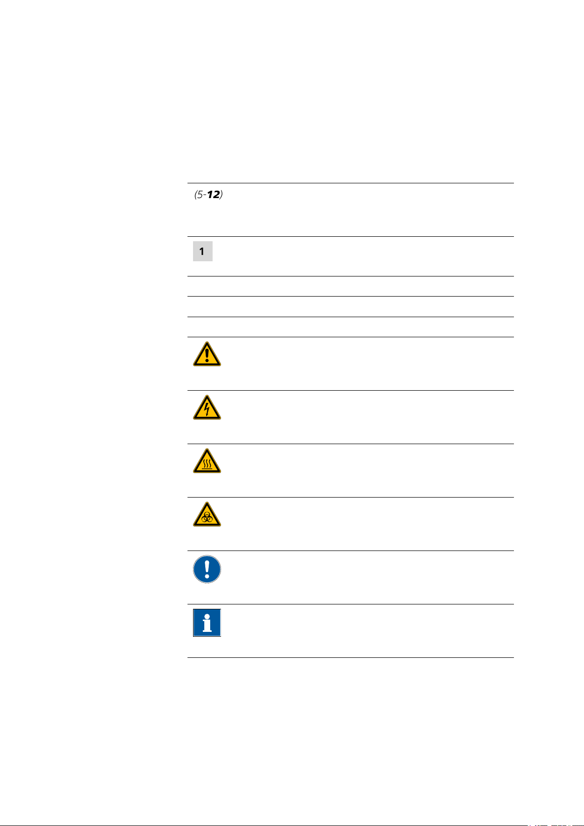
The following symbols and formatting may appear in this documentation:
Cross-reference to figure legend
The first number refers to the figure number, the second to the instrument part in the figure.
Instruction step
Carry out these steps in the sequence shown.
Method Dialog text, parameter in the software
File ▶ New Menu or menu item
[Next] Button or key
2 Introduction
WARNING
This symbol draws attention to a possible life-threatening hazard or risk of injury.
WARNING
This symbol draws attention to a possible hazard due
to electrical current.
WARNING
This symbol draws attention to a possible hazard due
to heat or hot instrument parts.
WARNING
This symbol draws attention to a possible biological
hazard.
CAUTION
This symbol draws attention to possible damage to
instruments or instrument parts.
NOTE
940 Professional IC Vario ONE/SeS/HPG (2.940.1440)
This symbol highlights additional information and
tips.
■■■■■■■■
7
Page 16
3.1 Front
3 Overview of the instrument
3.1 Front
■■■■■■■■■■■■■■■■■■■■■■
1
3
■■■■■■■■
8
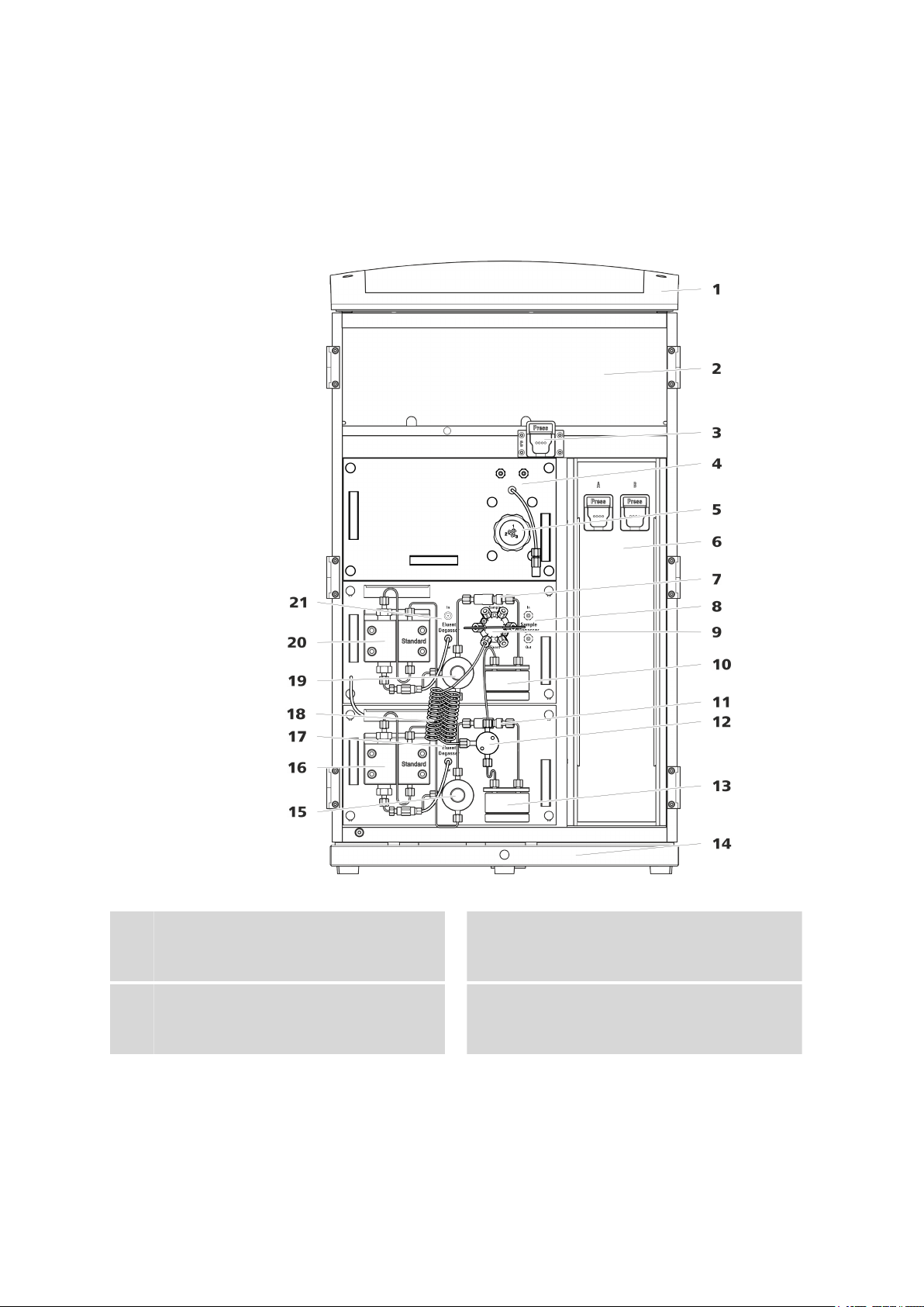
Figure 1 Front
Bottle holder
Offers space for the eluent bottle and additional accessories.
Column holder
For a third separation column outside the
column thermostat.
Detector chamber
2
Offers space for two embedded detectors
and additional accessories.
Metrohm CO2 Suppressor (MCS)
4
940 Professional IC Vario ONE/SeS/HPG (2.940.1440)
Page 17

■■■■■■■■■■■■■■■■■■■■■■
3 Overview of the instrument
Suppressor
5
Inline filter
7
Injection valve
9
Inline filter
11
Pulsation absorber
13
Purge valve
15
For deaerating the high-pressure pump.
Eluent degasser
17
Removes air bubbles from the eluent.
Purge valve
19
For deaerating the high-pressure pump.
Eluent degasser
21
Removes air bubbles from the eluent.
Column thermostat
6
With two column holders for two separation
columns.
Sample degasser
8
Removes air bubbles from the sample.
Pulsation absorber
10
Mixing valve
12
Base tray
14
With leak sensor.
High-pressure pump
16
Pumps the eluent through the IC system.
Mixing coil
18
High-pressure pump
20
Pumps the eluent through the IC system.
940 Professional IC Vario ONE/SeS/HPG (2.940.1440)
■■■■■■■■
9
Page 18
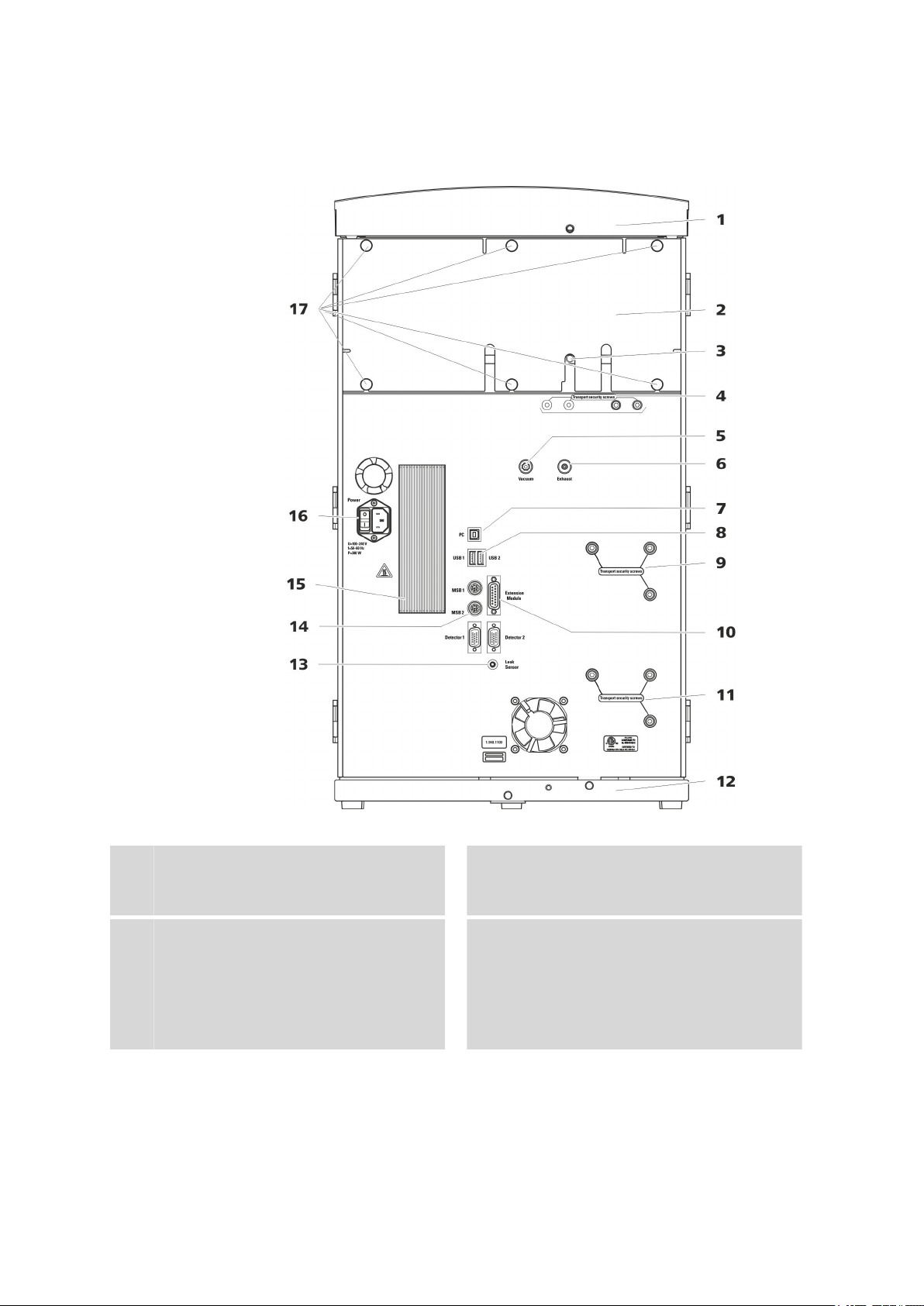
3.2 Rear
3.2 Rear
■■■■■■■■■■■■■■■■■■■■■■
■■■■■■■■
10
Figure 2 Rear
Bottle holder
1
Offers space for the eluent bottle and additional accessories.
Drainage tubing connection
3
For connecting the drainage tubing, which
guides escaped liquids away from the detector chamber.
Back panel
2
Removable. Enables access to the detector
chamber.
Transport locking screws
4
For securing the vacuum pump(s) when
transporting the instrument. Up to two vacuum pumps can be installed in an instrument. Only two transport locking screws are
used if just one vacuum pump is installed.
940 Professional IC Vario ONE/SeS/HPG (2.940.1440)
Page 19

■■■■■■■■■■■■■■■■■■■■■■
3 Overview of the instrument
Vacuum connection
5
For connecting an Extension Module that
has a degasser but not its own vacuum
pump. This connection has to be firmly
sealed with a stopper when not in use.
PC connection socket
7
For connecting the instrument to the computer with the USB cable (6.2151.020).
Transport locking screws
9
For securing the high-pressure pump (in the
middle plug-in) when transporting the
instrument.
Transport locking screws
11
For securing the high-pressure pump (in the
bottom plug-in) when transporting the
instrument. These screws are only installed if
a plug-in with a high-pressure pump is used
in the bottom slot.
Leak sensor connection socket
13
Labeled Leak Sensor. For connecting the
leak sensor connection cable coiled up in
the base tray.
Exhaust opening
6
Labeled Exhaust. For extracting the air from
the vacuum chamber.
USB connection sockets
8
Labeled USB 1 and USB 2. For connecting
USB devices.
Extension Module connection socket
10
Labeled Extension Module. For connecting
the cable (6.2156.060) used for connecting
the instrument to the Extension Module.
Base tray
12
With leak sensor and leak sensor cable.
MSB connection sockets
14
Labeled MSB 1 and MSB 2. For connecting
MSB devices.
Cooler
15
For cooling the power supply unit. May
become hot!
Knurled screws
17
For fastening the removable back panel.
Power socket
16
Power socket for connecting the power
cable and power switch for switching the
instrument on and off.
940 Professional IC Vario ONE/SeS/HPG (2.940.1440)
■■■■■■■■
11
Page 20

4.1 Setting up the instrument
4 Installation
4.1 Setting up the instrument
4.1.1 Packaging
The instrument is supplied in highly protective special packaging together
with the separately packed accessories. Keep this packaging, as only this
ensures safe transportation of the instrument.
4.1.2 Checks
Immediately after receipt, check whether the shipment has arrived complete and without damage by comparing it with the delivery note.
4.1.3 Location
The instrument has been developed for operation indoors and may not be
used in explosive environments.
■■■■■■■■■■■■■■■■■■■■■■
Place the instrument in a location of the laboratory which is suitable for
operation, free of vibrations, protected from corrosive atmosphere, and
contamination by chemicals.
The instrument should be protected against excessive temperature fluctuations and direct sunlight.
4.2 Removing the handle
The instrument is equipped with a handle in order to make it easier to
transport. The handle can be removed once the instrument is in place in
the lab.
Accessories
You do not need any accessories for the following work steps.
■■■■■■■■
12
940 Professional IC Vario ONE/SeS/HPG (2.940.1440)
Page 21
■■■■■■■■■■■■■■■■■■■■■■
4 Installation
Removing the handle
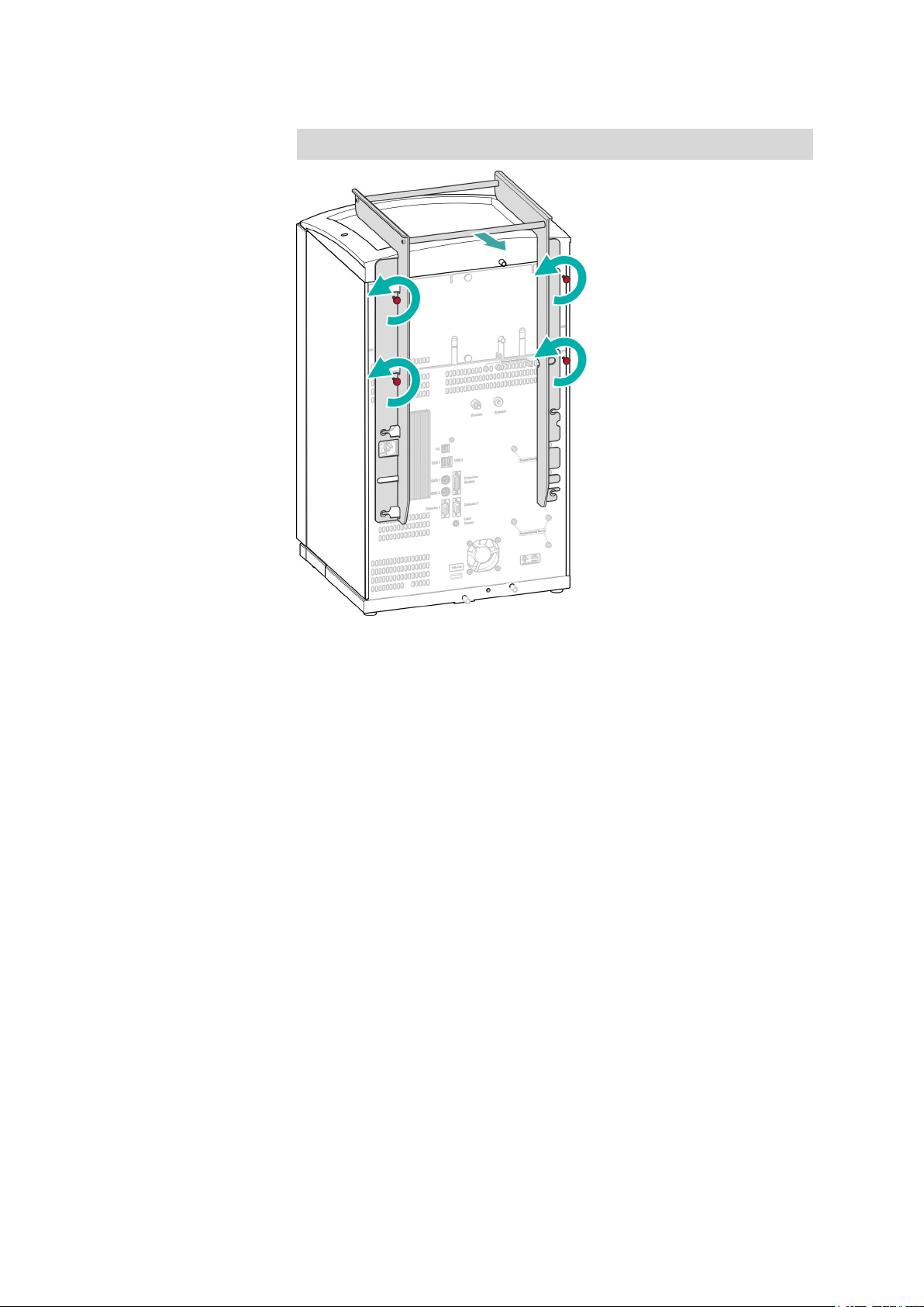
4.3 Removing transport locking screws
To avoid damage to the drives for the high-pressure pump and the vacuum pump during transport, the pumps are secured with transport locking screws. These are located at the rear of the instrument and labeled
with Transport security screws.
Remove these transport locking screws before the initial start-up.
Accessories
For this step you need:
■ Hex key 4 mm (6.2621.030)
940 Professional IC Vario ONE/SeS/HPG (2.940.1440)
■■■■■■■■
13
Page 22

4.3 Removing transport locking screws
Remove the transport locking screws
■■■■■■■■■■■■■■■■■■■■■■
Figure 3 Removing the transport locking screws
Transport locking screws
1
For the vacuum pump.
Transport locking screws
3
For an additional high-pressure pump in the
bottom drawer.
Store the transport locking screws in a safe place. Reinsert the transport
locking screws each time you transport the instrument a significant distance.
The pumps may be damaged if you transport the instrument without
inserting the transport locking screws.
CAUTION
Transport locking screws
2
For the high-pressure pump.
■■■■■■■■
14
940 Professional IC Vario ONE/SeS/HPG (2.940.1440)
Page 23

■■■■■■■■■■■■■■■■■■■■■■
4 Installation
4.4 Connecting the drainage tubing and leak sensor
The leak sensor detects leaking liquid that collects in the instrument's base
tray. Liquid that leaks in the bottle holder or in the detector chamber is
routed to the base tray using drainage tubing and is detected there.
If the leak sensor detects a leak in the IC system, the IC instrument is
switched off and a warning is output in the software.
The leak sensor functions properly only if the following preconditions are
met:
■ The drainage tubing is connected.
■ The leak sensor connection cable is inserted into the leak sensor con-
nection socket.
■ The 940 Professional IC Vario is switched on.
■ The leak sensor is switched to active in the software.
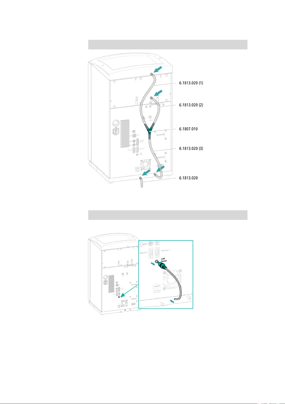
4.4.1 Installing the drainage tubing
Liquid that leaks in the bottle holder or detector chamber flows to the rear
of the instrument and is drained through openings on the bottle holder
and in the detector chamber. The drainage tubing has to be mounted at
these openings. This drainage tubing guides the leaking liquid to the base
tray where the leak sensor is located.
Accessories
For this step you need the following parts from the accessory kit: Vario/
Flex Basic (6.5000.000):
■ 2 × silicone tubing (6.1816.020)
■ Y connector (6.1807.010)
You also need scissors.
940 Professional IC Vario ONE/SeS/HPG (2.940.1440)
■■■■■■■■
15
Page 24
4.4 Connecting the drainage tubing and leak sensor
Connecting the drainage tubing
■■■■■■■■■■■■■■■■■■■■■■
4.4.2 Connecting the leak sensor
Plugging in the leak sensor connection cable
The leak sensor connection cable is coiled up in the base tray.
■■■■■■■■
16
940 Professional IC Vario ONE/SeS/HPG (2.940.1440)
Page 25

■■■■■■■■■■■■■■■■■■■■■■
4.5 Column thermostat
The column thermostat is completely connected. No installation work is
required.
4.6 Connecting the eluent bottle
The eluent is aspirated out of the eluent bottle via the eluent aspiration
tubing . The eluent aspiration tubing is installed on the input for the eluent degasser.
4 Installation
Accessories
For this step you need the following accessories:
These parts are part of the accessory kit Vario/Flex ONE (6.5000.010).
■ Eluent bottle (6.1608.070)
■ The eluent bottle cap GL 45 accessory set (6.1602.160)
This accessory set contains the bottle cap, an M6 tubing nipple, an M8
tubing nipple, two O-rings and an M6 and M8 threaded stopper.
■ The tubing adapter for aspiration filter accessory set (6.2744.210)
This accessory set contains a filter holder, a clamping screw and tubing
weighting.
■ An aspiration filter (6.2821.090)
940 Professional IC Vario ONE/SeS/HPG (2.940.1440)
■■■■■■■■
17
Page 26

4.6 Connecting the eluent bottle
■■■■■■■■■■■■■■■■■■■■■■
Connecting the eluent aspiration tubing
■■■■■■■■
18
940 Professional IC Vario ONE/SeS/HPG (2.940.1440)
Page 27

■■■■■■■■■■■■■■■■■■■■■■
4.7 Connecting the eluent degasser
The eluent degasser is completely connected. No installation work is
required.
4.8 Installing the high-pressure pump
The high-pressure pump is completely connected. No installation work is
required.
4.9 Installing an inline filter
The inline filter is completely connected. No installation work is required.
4.10 Installing the pulsation absorber
4 Installation
The pulsation absorber is installed between the high-pressure pump and
the injection valve. It protects the separation column from damage caused
by pressure fluctuations such as those when switching the injection valve,
and reduces interfering pulsations during highly sensitive measurements.
The pulsation absorber is completely connected. No installation work is
required.
4.11 Injection valve
The injection valve is completely connected. No installation work is
required.
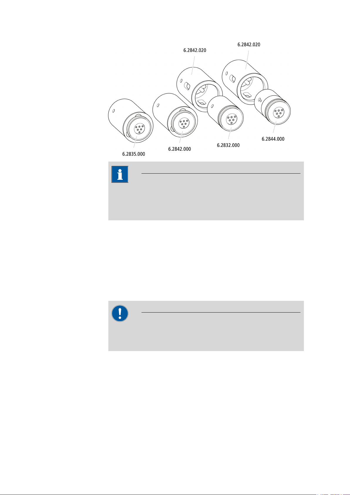
4.12 Suppressor
The suppressor drive of the 940 Professional IC Vario can hold various
rotors. The large rotors such as the SPM Rotor A (6.2835.000) and the
MSM-HC Rotor A (6.2842.000) can be inserted directly.
Small rotors like the MSM Rotor A (6.2832.000) and the MSM-LC Rotor A
(6.2844.000) must first be fitted into the adapter (6.2842.020) which can
then be inserted into the suppressor housing.
A connecting piece (6.2835.010) is used for all rotors for connecting the
suppressor to the IC system.
940 Professional IC Vario ONE/SeS/HPG (2.940.1440)
■■■■■■■■
19
Page 28
4.12 Suppressor
■■■■■■■■■■■■■■■■■■■■■■
NOTE
The instruments are supplied without rotor and without adapter.
The suitable rotor and the adapter, if required, must be ordered separately.
4.12.1 Inserting the rotors
Accessories
For this step you need the following accessories:
■ For the suppression: MSM Rotor A (6.2832.000) or MSM-HC Rotor A
(6.2842.000) or MSM-LC Rotor A (6.2844.000)
■ Optional: Adapter (6.2842.020)
■ Connecting piece (6.2835.010)
Large rotors can be directly inserted into the rotor housing.
The rotor may be destroyed during start-up if not inserted correctly.
Therefore, follow the following instructions exactly.
CAUTION
■■■■■■■■
20
940 Professional IC Vario ONE/SeS/HPG (2.940.1440)
Page 29

■■■■■■■■■■■■■■■■■■■■■■
4 Installation
Inserting large rotors
Inserting small rotors
You need the adapter (6.2842.020) in order to insert a small rotor into the
suppressor drive.
4.12.2 Connecting the suppressor
The three inputs and outputs of the suppressor units, numbered with 1, 2
and 3 on the connecting piece, each have 2 fixed mounted PTFE capillaries.
940 Professional IC Vario ONE/SeS/HPG (2.940.1440)
■■■■■■■■
21
Page 30

4.12 Suppressor
■■■■■■■■■■■■■■■■■■■■■■
Figure 4 Suppressor – connection capillaries
out
1
Output capillary for the eluent.
regenerant
3
Input capillary for the regeneration solution.
waste rins.
5
Output capillary for the rinsing solution; to
the waste container.
Recommended installation
in
2
Input capillary for the eluent.
waste reg.
4
Output capillary for the regeneration solution; to the waste container.
rinsing solution
6
Input capillary for the rinsing solution.
■■■■■■■■
22
940 Professional IC Vario ONE/SeS/HPG (2.940.1440)
Page 31

■■■■■■■■■■■■■■■■■■■■■■
Accessories
4 Installation
Alternative installation
Installing bottles with auxiliary solutions
To connect the bottles of the auxiliary solutions, you will need the following accessories:
■ Accessories from IC equipment: Dosino Regeneration (6.5330.190)
940 Professional IC Vario ONE/SeS/HPG (2.940.1440)
■■■■■■■■
23
Page 32

4.13 Metrohm CO2 Suppressor (MCS)
4.13 Metrohm CO2 Suppressor (MCS)
4.13.1 Connecting the MCS
The MCS is connected between the suppressor and the detector.
Connecting the MCS
■■■■■■■■■■■■■■■■■■■■■■
Figure 5 Connecting the MCS
Air aspiration capillary
1
For drawing in air with low CO2 content (via
the CO2 adsorption cartridge).
Luer coupling (6.2744.120)
3
Mounted on the air aspiration capillary with
a pressure screw (6.2744.070).
CAUTION
If the MCS is not used, the input and output must be sealed with the
threaded stoppers (6.2744.220).
4.13.2 Installing adsorption cartridges
The suctioned air has to have the lowest CO2 content possible in order for
the CO2 to be removed from the eluent as efficiently as possible. In order
to achieve this, the air is aspirated through a CO2 adsorption cartridge
(6.2837.000).
Pressure screw, short (6.2744.070)
2
Installed on the air aspiration capillary.
■■■■■■■■
24
However, the CO2 adsorption cartridge is sensitive to humidity; the CO
2
adsorption cartridge becomes clogged when wet. In order to protect the
940 Professional IC Vario ONE/SeS/HPG (2.940.1440)
Page 33

■■■■■■■■■■■■■■■■■■■■■■
CO2 adsorption cartridge, an H2O adsorption cartridge (6.2837.010) is
also installed.
Accessories For this step you need the following accessories:
■ Adsorption cartridge holder (6.2057.080) with 4 clips, an adapter
(6.1808.190) and a piece of PVC tubing.
■ CO
■ H
adsorption cartridge (6.2837.000)
2
O adsorption cartridge (6.2837.010)
2
All of the parts are located in one accessory kit: Vario/Flex SeS
(6.5000.020).
Installing the adsorption cartridge
CAUTION
4 Installation
The following preparatory steps absolutely must be carried out for CO
suppression to operate correctly.
Preparing the adsorption cartridges:
■ Prepare the H
O adsorption cartridge for use as specified in the provi-
2
ded leaflet.
■ Remove the protective cap on the tip of the CO
adsorption cartridge.
2
2
940 Professional IC Vario ONE/SeS/HPG (2.940.1440)
■■■■■■■■
25
Page 34

4.14 Installing the detector
■■■■■■■■■■■■■■■■■■■■■■
4.14 Installing the detector
The 940 Professional IC Vario provides enough space for two detectors
and additional accessories in the detector chamber. The detectors are
available as accessories and are supplied with separate manuals.
Placing the detector in the instrument
Follow the instructions in the chapter Inserting the detector in the manual
for the detector.
Connecting the detector to the eluent path
Accessories
For this step you need the following accessories:
■ Pressure screw, long (6.2744.090)
■■■■■■■■
26
940 Professional IC Vario ONE/SeS/HPG (2.940.1440)
Page 35

■■■■■■■■■■■■■■■■■■■■■■
4.15 Connecting the sample degasser (optional)
Gas bubbles in the sample lead to poor reproducibility, as the quantity of
sample in the sample loop is not always the same. Therefore, we recommend degassing samples that contain gas before injection.
NOTE
The sample degasser does not have to be connected. We recommend
only using the sample degasser if the application requires it.
The rinsing time increases by at least 2 minutes when the sample
degasser is connected.
4 Installation
Accessories
For this step you need the following accessories:
■ 2 × pressure screw, long (6.2744.090)
■ PTFE capillary (6.1803.040)
Connecting the sample degasser
If the sample degasser is not used, the input and output must be
sealed with threaded stoppers (6.2744.220).
940 Professional IC Vario ONE/SeS/HPG (2.940.1440)
CAUTION
■■■■■■■■
27
Page 36

4.16 Installing the high-pressure gradient module
■■■■■■■■■■■■■■■■■■■■■■
4.16 Installing the high-pressure gradient module
The outputs of the two high-pressure pumps are connected to the injection valve's eluent input using the mixing coil for high-pressure gradients
(6.2758.000).
Connect the two pieces of eluent aspiration tubing to an eluent bottle
(see Chapter 4.6, page 17).
4.17 Connecting the instrument to a computer
NOTE
The instrument must be switched off when being connected to a computer.
Accessories
For this step you need the following accessories:
■ USB connecting cable (6.2151.020)
■■■■■■■■
28
940 Professional IC Vario ONE/SeS/HPG (2.940.1440)
Page 37

■■■■■■■■■■■■■■■■■■■■■■
4 Installation
Connecting the USB cable
4.18 Connecting the instrument to the power supply
WARNING
The power supply unit must not get wet. Protect it from liquids.
Accessories
For this step you need the following accessories:
■ For Switzerland, …: Power supply cable with IEC 60320 line socket,
type C13, with SEV 1011 plug, type 12 (6.2122.020), 1.5 m
■ For Germany, …: Power supply cable with IEC 60320 line socket, type
C13, with CEE 7 plug, type VII (6.2122.040), 1.5 m
■ For the USA, …: Power supply cable with IEC 60320 line socket, type
C13, with NEMA 5-15 plug, type 498 (6.2122.070), 1.5 m
940 Professional IC Vario ONE/SeS/HPG (2.940.1440)
■■■■■■■■
29
Page 38

4.19 Initial start-up
■■■■■■■■■■■■■■■■■■■■■■
Connecting the power supply cable
1
Inserting the power supply cable
■ Insert the power supply cable into the instrument's power socket.
■ Connect the power supply cable to the power supply.
2
Switching on the instrument
Switch on the instrument using the power switch.
After being switched on, the LED on the front of the instrument
flashes. The instrument conducts a system test and establishes a connection to the software. Once the system test is complete and the
connection to the software has been established, the LED lights up
continuously.
4.19 Initial start-up
Even before the guard column and separation column are installed, the
entire system has to be completely rinsed with eluent for the first time.
■■■■■■■■
30
940 Professional IC Vario ONE/SeS/HPG (2.940.1440)
Page 39

■■■■■■■■■■■■■■■■■■■■■■
4 Installation
Rinsing the IC system
CAUTION
The guard column and separation column must not be installed for the
initial start-up.
Make sure that a coupling (6.2744.040) is being used instead of the
columns.
1
Preparing the software
■ Start the MagIC Net computer program.
■ Open the Equilibration tab in MagIC Net: Work-
place ▶ Run ▶ Equilibration.
■ Select (or create) a suitable method.
Also see: MagIC Net tutorial and online help.
2
Preparing the instrument
■ Ensure that the eluent aspiration tubing is immersed in the eluent
and there is enough eluent in the eluent bottle.
■ STREAM method (recommended): Ensure that the aspiration tub-
ing for the regeneration solution is immersed in the solution and
that there is enough solution; also check that the detector output
capillary is connected to the suppressor's input capillary for rinsing
solution (labeled rinsing solution).
Alternatively, if two bottles are being used for rinsing and regeneration: Ensure that the aspiration tubings for the auxiliary solutions (regeneration solution and rinsing solution) are immersed in
the respective solutions and that there is enough solution in both
bottles.
■ Switch on the instrument.
MagIC Net detects the instrument and all of its modules.
3
Starting equilibration
■ Start the equilibration in MagIC Net: Workplace ▶ Run ▶ Equi-
libration ▶ Start HW.
940 Professional IC Vario ONE/SeS/HPG (2.940.1440)
■■■■■■■■
31
Page 40

4.20 Connecting and rinsing the guard column
4
Deaerating the high-pressure pump
■■■■■■■■■■■■■■■■■■■■■■
Use the syringe to aspirate eluent until there are no more air
bubbles in the eluent.
5
Rinsing the instrument without columns
■ Rinse the instrument (without columns) with eluent for 5 minutes.
4.20 Connecting and rinsing the guard column
CAUTION
New guard columns are filled with solution and sealed with stoppers or
caps on both sides.
Before inserting the guard column, ensure that this solution can be
mixed with the eluent being used (follow information from the manufacturer).
■■■■■■■■
32
940 Professional IC Vario ONE/SeS/HPG (2.940.1440)
Page 41

■■■■■■■■■■■■■■■■■■■■■■
NOTE
The guard column may not be connected until after the instrument has
already been put into operation once (see Chapter 4.19, page 30). The
guard column and separation column have to be replaced by a coupling
(6.2744.040) until then.
Accessories For this step you need the following accessories:
■ Guard column (suitable for the separation column)
Connecting the guard column
4 Installation
Rinsing the guard column
1
Rinsing the guard column
■ Place a beaker under the guard column's output.
■ Start manual control in MagIC Net and select the high-pressure
pump: Manual ▶ Manual control ▶ Pump
– Flow: in accordance with column leaflet
– On
■ Rinse the guard column with eluent for approx. 5 minutes.
■ Use manual control in MagIC Net to stop the high-pressure pump
again: Off.
940 Professional IC Vario ONE/SeS/HPG (2.940.1440)
■■■■■■■■
33
Page 42

4.21 Connecting the separation column
4.21 Connecting the separation column
CAUTION
New separation columns are filled with solution and sealed with stoppers on both sides. Before inserting the column, ensure that this solution can be mixed with the eluent being used (follow information from
the manufacturer).
NOTE
The separation column may not be connected until after the instrument
has already been put into operation once (see Chapter 4.19, page 30).
The guard column and separation column have to be replaced by a
coupling (6.2744.040) until then.
■■■■■■■■■■■■■■■■■■■■■■
■■■■■■■■
34
940 Professional IC Vario ONE/SeS/HPG (2.940.1440)
Page 43

■■■■■■■■■■■■■■■■■■■■■■
4 Installation
Rinse the separation column as follows.
Connecting the separation column
1
Rinsing the separation column
■ Place a beaker under the separation column's outlet.
■ Start manual control in MagIC Net and select the high-pressure
pump: Manual ▶ Manual control ▶ Pump
– Flow: in accordance with column leaflet
– On
940 Professional IC Vario ONE/SeS/HPG (2.940.1440)
■■■■■■■■
35
Page 44
4.22 Conditioning
■ Rinse the separation column with eluent for approximately 10
■ Use manual control in MagIC Net to stop the high-pressure pump
4.22 Conditioning
After installation, after each time the instrument is switched on and after
each time the eluent is changed, the system has to be conditioned with
eluent long enough that a stable baseline is attained.
The conditioning time can lengthen considerably after changing the
eluent.
Conditioning the system
■■■■■■■■■■■■■■■■■■■■■■
minutes.
again: Off.
NOTE
1
Preparing the software
CAUTION
Ensure that the configured flow is not higher than the flow permitted for the corresponding column (refer to the column leaflet and
the chip data record).
■ Start the MagIC Net computer program.
■ Open the Equilibration tab in MagIC Net: Work-
place ▶ Run ▶ Equilibration.
■ Select (or create) a suitable method.
Also see: MagIC Net tutorial and online help.
2
Preparing the instrument
■ Ensure that the column is inserted correctly in relation to the flow
direction marked on the sticker (arrow has to point in the direction of flow).
■ Ensure that the eluent aspiration tubing is immersed in the eluent
and there is enough eluent in the eluent bottle.
3
Starting equilibration
■ Start the equilibration in MagIC Net: Workplace ▶ Run ▶ Equi-
libration ▶ Start HW.
■■■■■■■■
36
940 Professional IC Vario ONE/SeS/HPG (2.940.1440)
Page 45

■■■■■■■■■■■■■■■■■■■■■■
■ Visually inspect whether all capillaries and their connections from
the high-pressure pump to the detector are leak-tight. If eluent is
leaking out anywhere, tighten the corresponding pressure screw
further, or loosen the pressure screw, check the end of the capillary and shorten it using the capillary cutter if necessary and
retighten the pressure screw.
4
Conditioning the system
Rinse the system with eluent until the required stability of the baseline is attained (normally 30 minutes).
The instrument is now ready for measuring samples.
4 Installation
940 Professional IC Vario ONE/SeS/HPG (2.940.1440)
■■■■■■■■
37
Page 46

5 Operation
■■■■■■■■■■■■■■■■■■■■■■
The 940 Professional IC Vario – ONE/SeS/HPG is operated solely using the
MagIC Net software. You can find information on operating the software
in the tutorial for MagIC Net or in the online help.
■■■■■■■■
38
940 Professional IC Vario ONE/SeS/HPG (2.940.1440)
Page 47

■■■■■■■■■■■■■■■■■■■■■■
6 Warranty (guarantee)
Metrohm guarantees that the deliveries and services it provides are free of
defects in materials, design or manufacturing.
The general warranty period is 36 months (exclusions below) from the
date of delivery, or 18 months in the event of continuous operation. The
warranty remains valid on the condition that the servicing is provided by a
service organization authorized by Metrohm at defined intervals and with
a defined scope.
The warranty period for anion suppressors of the type "MSM" is 120
months from the date of delivery or 60 months in the case of continuous
operation.
The warranty period for IC separation columns is 90 days after start-up.
For third-party components that are recognizable as such, the manufacturer's warranty regulations apply.
6 Warranty (guarantee)
For instruments sold under the Metrohm NIRSystems brand, a full 16month warranty is applicable. In the event of continuous operation, the
warranty period is reduced by half.
Consumables and materials with limited storage life and glass breakage in
the case of electrodes or other glass parts are excluded from the warranty.
Warranty claims cannot be asserted if the ordering party has failed to
meet its payment obligations according to schedule.
During the warranty period, Metrohm undertakes either to replace free of
charge or to credit the purchaser for any modules or components that can
be shown to be faulty. Any transport or customs fees that may apply are
the responsibility of the ordering party.
The precondition for this is that the ordering party has to specify the article number, the article designation, an adequate error description, the
delivery date and (if applicable) the serial number or chip data in the Support Tracker. Metrohm then decides whether a replacement or a credit
note is to be issued or whether the faulty part has to be returned using
the Return Material Authorization (RMA). If a replacement or credit note is
issued, the ordering party undertakes to store the faulty part for at least
24 months in accordance with the current storage directives (in compliance with ESD guidelines) and to hold it in readiness for onsite inspection
or for return shipment to Metrohm. Metrohm reserves the right to invoice
the ordering party for these articles, including retroactively, in the event of
noncompliance with these preconditions.
940 Professional IC Vario ONE/SeS/HPG (2.940.1440)
■■■■■■■■
39
Page 48

■■■■■■■■■■■■■■■■■■■■■■
The same warranty periods that are specified for a corresponding new
part apply to parts that are replaced or repaired within the above-mentioned warranty periods. However, replacement or repair of a part does
not extend the warranty period of the entire system.
Deficiencies arising from circumstances that are not the responsibility of
Metrohm, such as improper storage or improper use, etc., are expressly
excluded from the warranty.
Metrohm also offers a 120-month spare parts availability guarantee and a
60-month PC software support warranty, calculated from the date on
which the product is withdrawn from the market. The content of this warranty is the ability of the customer to obtain functioning spare parts or
appropriate software support at market prices during the time of the warranty period. This does not apply for software products sold under the
Metrohm NIRSystems brand.
If Metrohm AG is unable to meet this obligation due to circumstances
beyond the control of Metrohm AG, then the ordering party shall be
offered alternative solutions at preferential conditions.
■■■■■■■■
40
940 Professional IC Vario ONE/SeS/HPG (2.940.1440)
Page 49

■■■■■■■■■■■■■■■■■■■■■■
7 Accessories
Up-to-date information on the scope of delivery and optional accessories
for your instrument can be found on the Internet.
When you receive your new instrument, we recommend downloading
the accessories list from the Internet, printing it out and keeping it
together with the manual for reference purposes.
Instruments currently sold
If you do not know the article number of your instrument, proceed as follows:
Downloading the accessories list
7 Accessories
NOTE
Go to the Metrohm website http://www.metrohm.com/com.
1
2
Click on .
The Search webpage will be displayed.
Enter a search term relating to the instrument into the search field
3
and click on Find.
The search results will be displayed.
In the search results, select the Devices tab (if it is not already
4
selected) and then click on the Metrohm article number of the
required instrument (e.g. 2.852.0050).
The page with information pertaining to the searched article is displayed.
Select the Parts tab.
5
The complete list of accessories with the scope of delivery and the
optional accessories will be displayed.
6
Click on .
940 Professional IC Vario ONE/SeS/HPG (2.940.1440)
■■■■■■■■
41
Page 50

■■■■■■■■■■■■■■■■■■■■■■
The Partslists webpage will be displayed.
Select the desired output language.
7
With the article number entered, click on the command Generate
8
PDF.
The PDF file with the accessories data will be created in the language
selected.
Direct access for all instruments
If you are unable to find your instrument using the search as described
above, this may be due to the instrument not being sold anymore. Using
the article number, you can download accessories lists for all instruments
as follows:
Downloading the accessories list
Type http://partslists.metrohm.com into your Internet browser.
1
The Partslists webpage will be displayed.
Select the desired output language.
2
Enter the article number and click on the Generate PDF command.
3
The PDF file with the accessories data will be created in the language
selected.
■■■■■■■■
42
940 Professional IC Vario ONE/SeS/HPG (2.940.1440)
Page 51

■■■■■■■■■■■■■■■■■■■■■■
Index
Index
A
Adsorption cartridges
Connection ........................ 24
Aspiration tubing for eluent ...... 18
B
Baseline
Conditioning ...................... 37
C
Cartridges
Connection ........................ 24
Column
See also "Separation column"
........................................... 34
Column thermostat
Installation ......................... 17
Computer connection ............... 28
Conditioning ............................ 37
Connect
To computer ...................... 28
To power supply ................. 29
D
Degasser
Sample degasser ................. 27
Drainage tubing
Installation ......................... 15
E
Electrostatic charge .................... 6
Eluent
Aspirate .............................. 18
Eluent bottle
Installation ......................... 17
Equilibration ....................... 31, 36
F
Filter
See also "Inline filter" .......... 19
G
Grip
Also see "Handle" ............... 12
Guarantee ................................ 39
Guard column
Installation ......................... 32
Rinse .................................. 33
H
Handle ..................................... 12
Heating
Also see "Column thermostat"
........................................... 17
High-pressure pump
Protection .......................... 14
I
IC column
See also "Separation column"
........................................... 34
Injection valve ............................ 3
Installation ......................... 19
Inline filter ................................ 19
Installation
Column thermostat ............ 17
Drainage tubing ................. 15
Eluent bottle ....................... 17
Guard column .................... 32
Injection valve .................... 19
Leak sensor ........................ 16
MCS ................................... 24
Pulsation absorber .............. 19
Sample degasser ................. 27
Separation column ............. 34
Suppressor ......................... 19
L
Leak sensor
Installation ......................... 16
Leak-tightness .......................... 32
M
Mains voltage ............................. 5
MCS
Capillary connection ........... 24
Connection for cartridges ... 24
Installation ......................... 24
P
Power connection .............. 29, 30
Pulsation absorber
Installation ......................... 19
R
Rinse
Guard column .................... 33
Separation column ............. 35
S
Safety instructions ...................... 5
Sample degasser
Installation ......................... 27
Separation column
Installation ......................... 34
Protection ...................... 3, 19
Rinse .................................. 35
Service ....................................... 5
Suppressor
Install rotor ......................... 19
Installation ......................... 19
Suppressor drive
See also: Suppressor ........... 19
Switch on ................................. 30
T
Thermostat
Also see "Column thermostat"
........................................... 17
Transport
Grip .................................... 12
Transport locking screws .......... 13
V
Vacuum pump
Protection .......................... 14
Valve
See also "Injection valve" .... 19
W
Warranty .................................. 39
940 Professional IC Vario ONE/SeS/HPG (2.940.1440)
■■■■■■■■
43
 Loading...