

Page 1
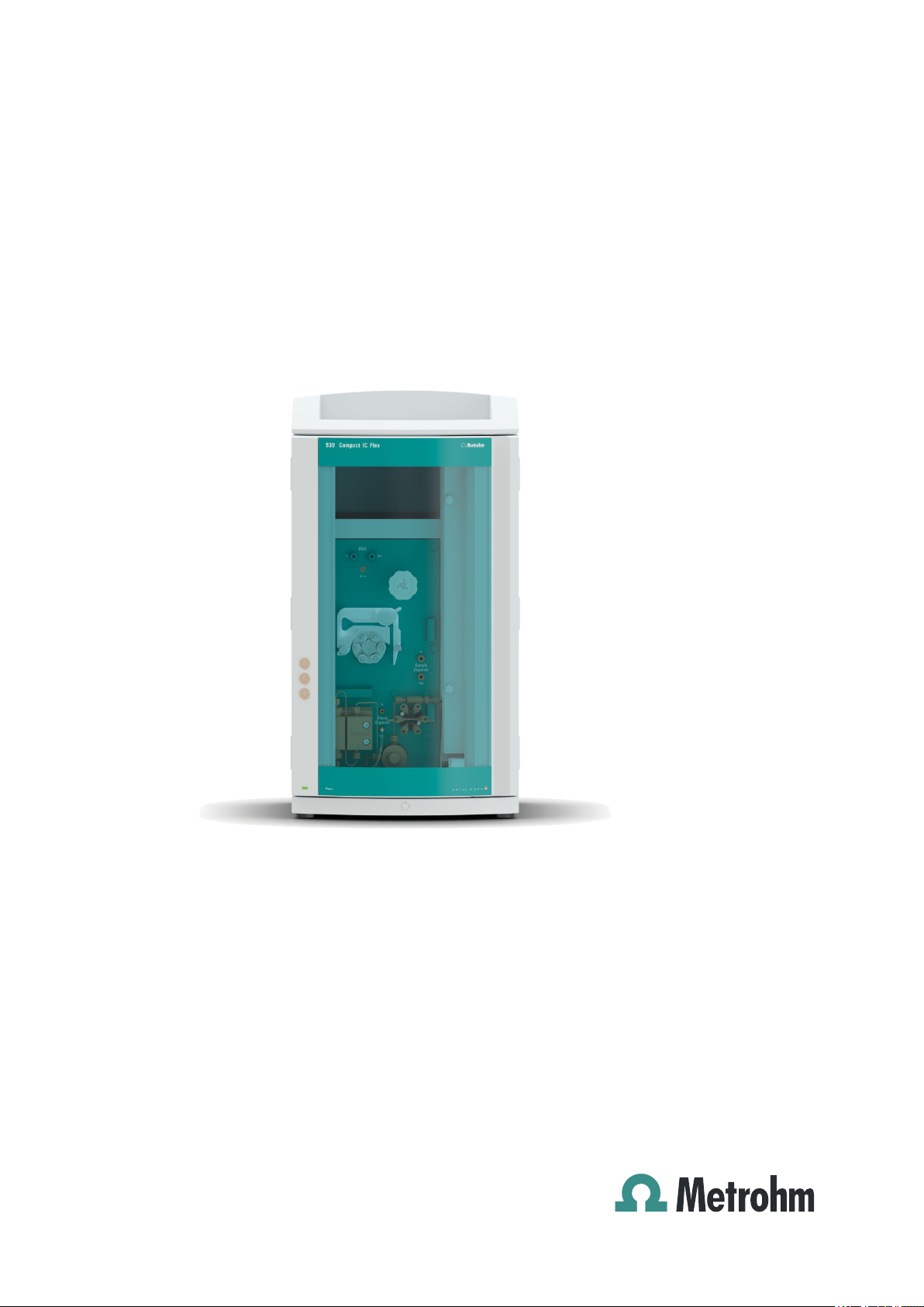
930 Compact IC Flex
930 Compact IC Flex Oven SeS/PP/Deg
Manual – Short Instructions
8.930.8120EN / 2017-07-31
Page 2

Page 3

Metrohm AG
CH-9100 Herisau
Switzerland
Phone +41 71 353 85 85
Fax +41 71 353 89 01
info@metrohm.com
www.metrohm.com
930 Compact IC Flex
930 Compact IC Flex Oven
SeS/PP/Deg
2.930.2560
8.930.8120EN / 2017-07-31
Manual – Short Instructions
zst
Page 4

Technical Communication
Metrohm AG
CH-9100 Herisau
techcom@metrohm.com
This documentation is protected by copyright. All rights reserved.
This documentation has been prepared with great care. However, errors
can never be entirely ruled out. Please send comments regarding possible
errors to the address above.
Page 5

■■■■■■■■■■■■■■■■■■■■■■
Table of contents
1 About these short instructions 1
2 Introduction 2
2.1 Instrument description ......................................................... 2
2.2 Intended use ......................................................................... 4
2.3 Safety instructions ................................................................ 5
2.3.1 General notes on safety ........................................................... 5
2.3.2 Electrical safety ........................................................................ 5
2.3.3 Tubing and capillary connections ............................................. 6
2.3.4 Flammable solvents and chemicals ........................................... 6
2.3.5 Recycling and disposal ............................................................. 6
2.4 Symbols and conventions .................................................... 7
3 Overview of the instrument 8
Table of contents
3.1 Front ...................................................................................... 8
3.2 Rear ........................................................................................ 9
4 Installation 11
4.1 Setting up the instrument .................................................. 11
4.1.1 Packaging .............................................................................. 11
4.1.2 Checks .................................................................................. 11
4.1.3 Location ................................................................................ 11
4.2 Capillary connections in the IC system ............................. 11
4.3 Removing transport locking screws .................................. 12
4.4 Connecting the drainage tubing and leak sensor ............ 14
4.4.1 Installing the drainage tubing ................................................ 14
4.4.2 Connecting the leak sensor .................................................... 15
4.5 Column oven ....................................................................... 16
4.6 Connecting the eluent bottle ............................................. 16
4.7 Connecting the eluent degasser ........................................ 18
4.8 Installing the high-pressure pump .................................... 19
4.9 Installing an inline filter ..................................................... 19
4.10 Installing the pulsation absorber ...................................... 19
4.11 Injection valve ..................................................................... 19
4.12 Metrohm Suppressor Module (MSM) ............................... 19
4.12.1 Inserting the rotors ................................................................ 20
4.12.2 Connecting the Metrohm Suppressor Module (MSM) ............. 21
930 Compact IC Flex Oven SeS/PP/Deg (2.930.2560)
■■■■■■■■
III
Page 6

Table of contents
■■■■■■■■■■■■■■■■■■■■■■
4.13 Peristaltic pump .................................................................. 24
4.13.1 Installing the peristaltic pump ................................................ 24
4.14 Metrohm CO2 Suppressor (MCS) ....................................... 26
4.14.1 Connecting the MCS ............................................................. 26
4.14.2 Installing adsorption cartridges .............................................. 26
4.15 Installing the conductivity detector .................................. 28
4.16 Installing the amperometric detector ............................... 29
4.17 Connecting the sample degasser (optional) ..................... 29
4.18 Connecting the instrument to a computer ....................... 30
4.19 Connecting the instrument to the power grid ................. 31
4.20 Initial start-up ..................................................................... 32
4.21 Connecting and rinsing the guard column ....................... 34
4.22 Connecting the separation column ................................... 35
4.23 Conditioning ........................................................................ 37
5 Operation 39
6 Accessories 40
Index 41
■■■■■■■■
IV
930 Compact IC Flex Oven SeS/PP/Deg (2.930.2560)
Page 7

■■■■■■■■■■■■■■■■■■■■■■
Table of figures
Figure 1 Front ................................................................................................. 8
Figure 2 Rear .................................................................................................. 9
Figure 3 Removing the transport locking screws ............................................ 13
Figure 4 Installing tubing weighting and aspiration filter ................................ 18
Figure 5 Metrohm Suppressor Module (MSM) – Connection capillaries .......... 22
Figure 6 Connecting the MCS ....................................................................... 26
Table of figures
930 Compact IC Flex Oven SeS/PP/Deg (2.930.2560)
■■■■■■■■
V
Page 8

Page 9

■■■■■■■■■■■■■■■■■■■■■■
1 About these short instructions
This short instruction manual contains important chapters from the comprehensive manual. In addition to an introduction, safety instructions and
an overview of the instrument, you will also find information about installing and operating the 930 Compact IC Flex Oven SeS/PP/Deg as well as
information regarding the warranty. You can download the comprehensive manual as a PDF file from the Internet.
Downloading the manual
You can find the detailed manual on the Internet under
http://www.metrohm.com/:
1. Enter the order number for your instrument as the search term (e.g.
2.930.2560).
2. Click on >More information.
3. Click on Documents.
All available documents for the instrument will be displayed.
4. Click on the PDF link to download the desired manual.
1 About these short instructions
930 Compact IC Flex Oven SeS/PP/Deg (2.930.2560)
■■■■■■■■
1
Page 10

2.1 Instrument description
2 Introduction
2.1 Instrument description
The 930 Compact IC Flex is a robust ion chromatograph. It is distinguished
by:
■ Its intelligence: All of the functions are monitored, optimized and docu-
mented in an FDA-compatible manner. Intelligent components, such as
iColumns, save important data onto a chip.
■ Its compact design: It has a small footprint.
■ Its transparency: All components are easily accessible and located for
simple visibility and can be monitored during operation through a large
window.
■ Its safety: The wet end and the electronics are physically separated,
thereby preventing fluids from coming into contact with the electronics
to a large extent. A leak sensor is integrated into the wet end.
■ Its environmental compatibility.
■ Its low noise emission.
■ The intelligent MagIC Net software.
■■■■■■■■■■■■■■■■■■■■■■
The 930 Compact IC Flex is operated using the MagIC Net software. A
USB cable is used to connect the instrument to a computer with
MagIC Net installed. The intelligent software detects the instrument automatically and checks its functionality. The software controls and monitors
the instrument, evaluates the measured data and manages it in a database.
The 930 Compact IC Flex Oven SeS/PP/Deg consists of the following modules:
Housing
The sturdy housing contains the instrument's electronic components,
including their interfaces and one connector for a separation column. In
addition, the housing provides space for a conductivity detector or an
amperometric detector. Capillaries and cables can be fed into and out of
the instrument through several openings.
Leak sensor
The leak sensor detects leaking liquid that collects in the instrument's base
tray. Liquid that leaks in the instrument is routed to the base tray using
drainage tubing and detected there.
■■■■■■■■
2
930 Compact IC Flex Oven SeS/PP/Deg (2.930.2560)
Page 11

■■■■■■■■■■■■■■■■■■■■■■
2 Introduction
Column oven
The column oven regulates the temperature for the separation column
and the eluent, thereby providing stable measuring conditions. There is a
column holder with chip reader in the column oven.
Eluent degasser
The eluent degasser removes gas bubbles and dissolved gases from the
eluent.
High-pressure pump
The intelligent and low-pulsation high-pressure pump pumps the eluent
through the IC system. It is equipped with a chip where its technical specifications and "life history" (operating hours, service data, etc.) are stored.
Inline filter
Inline filters protect the separation column reliably from potential contamination from the eluent. The filter pads with 2 µm pore size can be
replaced quickly and easily. They remove particles from the solutions, such
as bacteria and algae.
Pulsation absorber
The pulsation absorber protects the separation column from damage
caused by pressure fluctuations, e.g. when the injection valve is switched,
and reduces interfering pulsations during highly sensitive measurements.
Injection valve
The injection valve connects the eluent path to the sample path. By a
quick and precise switching of the valve, a quantity of sample solution
defined by the size of the sample loop is injected and flushed to the separation column with the eluent.
Metrohm Suppressor Module (MSM)
The chemical suppressor MSM consists of the suppressor drive, a rotor
and, where applicable, an adapter. The suppressor drive gives you the flexibility to use different rotors according to the principle "one drive – many
rotors". Suppression rotors with different capacities and construction or a
rotor for sample preparation (SPM Rotor) are readily interchangeable with
appropriate adapters as needed. The rotors are not included in the instrument's scope of delivery. The rotor required for the application and any
adapter that is required must be ordered separately.
Peristaltic pump
The peristaltic pump is used for pumping sample and auxiliary solutions. It
can rotate in both directions.
930 Compact IC Flex Oven SeS/PP/Deg (2.930.2560)
■■■■■■■■
3
Page 12

2.2 Intended use
■■■■■■■■■■■■■■■■■■■■■■
Metrohm CO2 Suppressor (MCS)
The Metrohm CO2 Suppressor (MCS) removes the CO2 from the eluent
stream. This lowers the background conductivity, improves detection sensitivity and minimizes the injection peak and system peak.
Detector
Metrohm offers a series of different detectors for various analysis tasks. A
suitable detector type must be ordered as a separate device.
Sample degasser
The sample degasser removes gas bubbles and dissolved gases from the
sample.
Separation column
The intelligent separation column separates different components according to their interactions with the column. Metrohm separation columns
are equipped with a chip where their technical specifications and history
(start-up, operating hours, injections etc) are stored.
2.2 Intended use
The 930 Compact IC Flex Oven SeS/PP/Deg is used for the determination
of anions, cations or polar substances with sequential suppression using
ion chromatography.
Sequential suppression consists of:
■ Chemical suppression with a Metrohm Suppressor Module (MSM) and
subsequent
■ CO
2
Background conductivity is reduced to a minimum with sequential suppression.
The instrument can also be used as needed for the determination of cations, polar substances or anions without suppression.
This instrument is suitable for processing chemicals and flammable samples. Therefore, the use of the 930 Compact IC Flex requires the user to
have basic knowledge and experience in handling toxic and caustic substances. Knowledge regarding the application of fire prevention measures
prescribed for laboratories is also mandatory.
suppression with the Metrohm CO2 Suppressor (MCS).
■■■■■■■■
4
930 Compact IC Flex Oven SeS/PP/Deg (2.930.2560)
Page 13
■■■■■■■■■■■■■■■■■■■■■■
2.3 Safety instructions
2.3.1 General notes on safety
WARNING
This instrument may only be operated in accordance with the specifications in this documentation.
This instrument has left the factory in a flawless state in terms of technical
safety. To maintain this state and ensure non-hazardous operation of the
instrument, the following instructions must be observed carefully.
2.3.2 Electrical safety
The electrical safety when working with the instrument is ensured as part
of the international standard IEC 61010.
WARNING
2 Introduction
Only personnel qualified by Metrohm are authorized to carry out service
work on electronic components.
WARNING
Never open the housing of the instrument. The instrument could be
damaged by this. There is also a risk of serious injury if live components
are touched.
There are no parts inside the housing which can be serviced or replaced
by the user.
Supply voltage
WARNING
An incorrect supply voltage can damage the instrument.
Only operate this instrument with a supply voltage specified for it (see
rear panel of the instrument).
930 Compact IC Flex Oven SeS/PP/Deg (2.930.2560)
■■■■■■■■
5
Page 14
2.3 Safety instructions
Protection against electrostatic charges
WARNING
Electronic components are sensitive to electrostatic charges and can be
destroyed by discharges.
Do not fail to pull the power cord out of the power socket before you
set up or disconnect electrical plug connections at the rear of the
instrument.
2.3.3 Tubing and capillary connections
CAUTION
Leaks in tubing and capillary connections are a safety risk. Tighten all
connections well by hand. Avoid applying excessive force to tubing connections. Damaged tubing ends lead to leakage. Appropriate tools can
be used to loosen connections.
■■■■■■■■■■■■■■■■■■■■■■
Check the connections regularly for leakage. If the instrument is used
mainly in unattended operation, then weekly inspections are mandatory.
2.3.4 Flammable solvents and chemicals
WARNING
All relevant safety measures are to be observed when working with
flammable solvents and chemicals.
■ Set up the instrument in a well-ventilated location (e.g. fume cup-
board).
■ Keep all sources of flame far from the workplace.
■ Clean up spilled liquids and solids immediately.
■ Follow the safety instructions of the chemical manufacturer.
2.3.5 Recycling and disposal
This product is covered by European Directive 2012/19/EU, WEEE – Waste
Electrical and Electronic Equipment.
■■■■■■■■
6
The correct disposal of your old instrument will help to prevent negative
effects on the environment and public health.
930 Compact IC Flex Oven SeS/PP/Deg (2.930.2560)
Page 15
■■■■■■■■■■■■■■■■■■■■■■
More details about the disposal of your old instrument can be obtained
from your local authorities, from waste disposal companies or from your
local dealer.
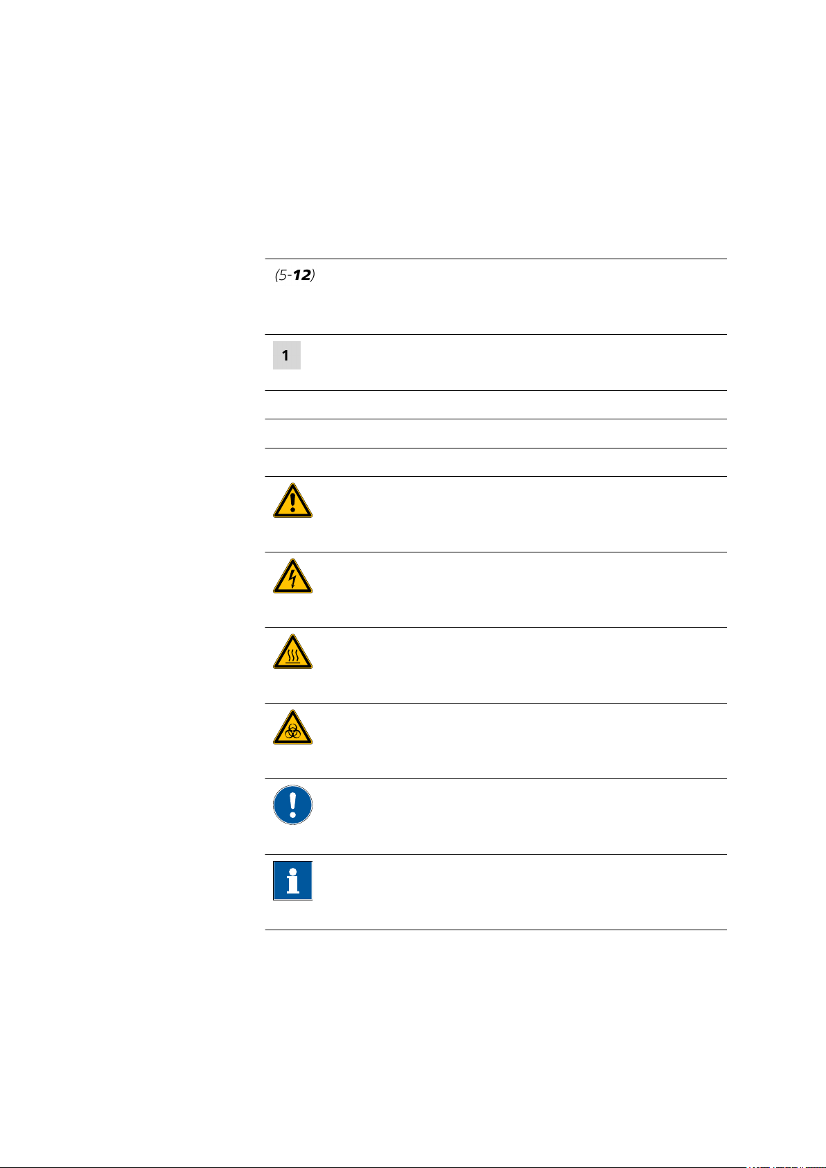
2.4 Symbols and conventions
The following symbols and formatting may appear in this documentation:
Cross-reference to figure legend
The first number refers to the figure number, the second to the instrument part in the figure.
Instruction step
Carry out these steps in the sequence shown.
Method Dialog text, parameter in the software
File ▶ New Menu or menu item
[Next] Button or key
2 Introduction
WARNING
This symbol draws attention to a possible life-threatening hazard or risk of injury.
WARNING
This symbol draws attention to a possible hazard due
to electrical current.
WARNING
This symbol draws attention to a possible hazard due
to heat or hot instrument parts.
WARNING
This symbol draws attention to a possible biological
hazard.
CAUTION
This symbol draws attention to possible damage to
instruments or instrument parts.
NOTE
930 Compact IC Flex Oven SeS/PP/Deg (2.930.2560)
This symbol highlights additional information and
tips.
■■■■■■■■
7
Page 16

3.1 Front
3 Overview of the instrument
3.1 Front
■■■■■■■■■■■■■■■■■■■■■■
1
3
5
7
9
■■■■■■■■
8
Bottle holder
Column oven
Sample degasser
Injection valve
Pulsation absorber
Figure 1 Front
Column holder
2
For hanging the separation column (iColumn). With column recognition.
Metrohm Suppressor Module (MSM)
4
Inline filter
6
Purge valve
8
Base tray
10
930 Compact IC Flex Oven SeS/PP/Deg (2.930.2560)
Page 17

■■■■■■■■■■■■■■■■■■■■■■
3 Overview of the instrument
High-pressure pump
11
Peristaltic pump
13
Detector chamber
15
Room for the detector and the adsorption
cartridge for the MCS.
3.2 Rear
Eluent degasser
12
Metrohm CO2 Suppressor (MCS)
14
Figure 2 Rear
Bottle holder
1
930 Compact IC Flex Oven SeS/PP/Deg (2.930.2560)
Drainage tubing connection
2
For connecting the drainage tubing, which
guides escaped fluids away from the bottle
holder.
■■■■■■■■
9
Page 18

3.2 Rear
■■■■■■■■■■■■■■■■■■■■■■
Knurled screws
3
For fastening the removable back panel.
Drainage tubing connection
5
For connecting the drainage tubing, which
guides escaped liquids away from the detector chamber.
Exhaust opening
7
Labeled Exhaust. For extracting the air from
the vacuum chamber.
Service connection socket
9
For Metrohm service only.
Drainage tubing connections
11
For connecting two drainage tubings that
guide the escaped fluid to the leak sensor
and from there to the waste container.
Type plate
13
Leak sensor connection socket
15
Labeled Leak Sensor. For connecting the
leak sensor connection cable.
Back panel
4
Removable. Enables access to the detector
chamber.
Transport locking screws
6
For securing the vacuum pump when transporting the instrument.
Auxiliary connection socket
8
For connecting an 891 Professional Analog
Out (2.891.0010).
Transport locking screws
10
For securing the high-pressure pump when
transporting the instrument.
Base tray
12
With leak sensor.
Serial number
14
Detector connection socket
16
Labeled Detector. For connecting Metrohm
detectors.
MSB connection sockets
17
Labeled MSB 1 and MSB 2. For connecting
MSB devices.
PC connection socket
19
For connecting the instrument to the computer with the USB cable (6.2151.020).
Power socket
21
Power socket for connecting the power
cable and power switch for switching the
instrument on and off.
USB connection sockets
18
Labeled USB 1 and USB 2. For connecting
USB devices.
Vacuum connection
20
Plugged with a stopper.
10
■■■■■■■■
930 Compact IC Flex Oven SeS/PP/Deg (2.930.2560)
Page 19

■■■■■■■■■■■■■■■■■■■■■■
4 Installation
4.1 Setting up the instrument
4.1.1 Packaging
The instrument is supplied in protective packaging together with the separately packed accessories. Keep this packaging, as only this ensures safe
transportation of the instrument.
4.1.2 Checks
Immediately after receipt, check whether the shipment has arrived complete and without damage by comparing it with the delivery note.
4.1.3 Location
The instrument has been developed for operation indoors and may not be
used in explosive environments.
4 Installation
Place the instrument in a location of the laboratory which is suitable for
operation, free of vibrations, protected from corrosive atmosphere, and
contamination by chemicals.
The instrument should be protected against excessive temperature fluctuations and direct sunlight.
4.2 Capillary connections in the IC system
Capillary connections
NOTE
Sprays of chemicals caused by capillaries slipping out
If you work with an increased system pressure (> 15 MPa), capillaries
may slip out of the pressure screws. This can lead to sprays of chemicals.
To avoid this, we recommend
■ degreasing the ends of the capillaries before installing them.
Dampen a cloth with acetone and wipe off the ends of the capillaries before connecting them with the pressure screws.
■ tightening the pressure screws firmly using a wrench (6.2739.000).
In order to achieve optimum analysis results, capillary connections in an IC
system must be absolutely tight and free of dead volume. Dead volume
930 Compact IC Flex Oven SeS/PP/Deg (2.930.2560)
■■■■■■■■
11
Page 20

4.3 Removing transport locking screws
occurs if two capillary ends connected to each other do not fit exactly,
thus allowing liquid to escape. There are two possible causes for this:
■ The capillary ends do not have exactly flat edges.
■ The two capillary ends do not completely meet.
One prerequisite for dead-volume-free capillary connection is that both
capillary ends are cut exactly flat. Therefore we recommend cutting PEEK
capillaries only with a capillary cutter (6.2621.080).
Also see: Cutting capillaries video on the Internet http://ic-
help.metrohm.com.
Creating dead-volume-free capillary connections
To create dead-volume-free capillary connections, proceed as follows:
1
2
3
4
■■■■■■■■■■■■■■■■■■■■■■
Wipe off the end of the capillary with a cloth dampened with acetone.
Slide the pressure screw over the capillary. Ensure that the capillary
protrudes 1 to 2 mm from the tip of the pressure screw.
Push the capillary into the connection or coupling as far as it will go
and hold it there.
Only then start turning the pressure screw. Hold the capillary in the
stop position while turning it shut.
4.3 Removing transport locking screws
To avoid damage to the drives for the high-pressure pump and the vacuum pump during transport, the pumps are secured with transport locking
screws. These are located at the rear of the instrument and labeled with
Transport security screws.
Remove these transport locking screws before the initial start-up.
Accessories
■■■■■■■■
12
For this step you need:
■ 4 mm hex key (6.2621.030)
930 Compact IC Flex Oven SeS/PP/Deg (2.930.2560)
Page 21

■■■■■■■■■■■■■■■■■■■■■■
4 Installation
Removing the transport locking screws
Figure 3 Removing the transport locking screws
Transport locking screws
1
For the vacuum pump. Only present if the
instrument has a degasser or a CO2 Suppressor (MCS).
Store the transport locking screws in a safe place. Reinsert the transport
locking screws each time you transport the instrument a significant distance.
The pumps may be damaged if you transport the instrument without
inserting the transport locking screws.
CAUTION
Transport locking screws
2
For the high-pressure pump.
930 Compact IC Flex Oven SeS/PP/Deg (2.930.2560)
■■■■■■■■
13
Page 22

4.4 Connecting the drainage tubing and leak sensor
■■■■■■■■■■■■■■■■■■■■■■
4.4 Connecting the drainage tubing and leak sensor
The leak sensor detects leaking liquid that collects in the instrument's base
tray. Liquid that leaks in the bottle holder or in the detector chamber is
conveyed to the base tray using drainage tubing and is detected there.
If the leak sensor detects a leak in the IC system, the IC instrument is
switched off. The software displays a warning.
The leak sensor functions properly only if the following preconditions are
met:
■ The drainage tubing is connected.
■ The leak sensor connection cable is inserted into the leak sensor con-
nection socket.
■ The 930 Compact IC Flex is switched on.
■ The leak sensor is switched to active in the software.
4.4.1 Installing the drainage tubing
Liquid that leaks in the bottle holder or detector chamber flows to the rear
of the instrument. Openings on the bottle holder and in the detector
chamber allow the liquid to drain. The drainage tubing has to be mounted
at these openings. This drainage tubing guides the leaking liquid to the
base tray where the leak sensor is located.
Accessories
For this step you need the following parts from the accessory kit: Vario/
Flex Basic (6.5000.000):
■ 2 × silicone tubing (6.1816.020)
■ Y connector (6.1807.010)
You also need scissors.
14
■■■■■■■■
930 Compact IC Flex Oven SeS/PP/Deg (2.930.2560)
Page 23

■■■■■■■■■■■■■■■■■■■■■■
4 Installation
Connecting the drainage tubing
4.4.2 Connecting the leak sensor
Plugging in the leak sensor connection cable
The leak sensor connection cable is coiled up in the base tray.
930 Compact IC Flex Oven SeS/PP/Deg (2.930.2560)
■■■■■■■■
15
Page 24

4.5 Column oven
4.5 Column oven
The column oven is completely connected. No installation work is
required.
4.6 Connecting the eluent bottle
The eluent is aspirated out of the eluent bottle via the eluent aspiration
tubing . The eluent aspiration tubing is installed on the entry to the eluent
degasser.
■■■■■■■■■■■■■■■■■■■■■■
Accessories
For this step, you need the following accessories:
These parts are part of the accessory kit Vario/Flex ONE (6.5000.010).
■ Eluent bottle (6.1608.070)
■ The eluent bottle cap GL 45 accessory set (6.1602.160)
This accessory set contains the bottle cap, an M6 tubing nipple, an M8
tubing nipple, two O-rings and an M6 and M8 threaded stopper.
■ The tubing adapter for aspiration filter accessory set (6.2744.210)
This accessory set contains a filter holder, a clamping screw and tubing
weighting.
■ An aspiration filter (6.2821.090)
■ The adsorber tube (6.1609.000)
■ The SGJ clip (6.2023.020)
16
■■■■■■■■
930 Compact IC Flex Oven SeS/PP/Deg (2.930.2560)
Page 25

■■■■■■■■■■■■■■■■■■■■■■
4 Installation
Connecting the eluent aspiration tubing
1
Pre-rinsing the aspiration filter
Always wear gloves when handling the aspiration filter.
In order to avoid air bubbles after the installation of the aspiration filter, we recommend pre-rinsing the aspiration filter with water or eluent.
930 Compact IC Flex Oven SeS/PP/Deg (2.930.2560)
NOTE
■■■■■■■■
17
Page 26

4.7 Connecting the eluent degasser
■■■■■■■■■■■■■■■■■■■■■■
For pre-rinsing, you will need the holder for the eluent aspiration filter (6.2744.360), a syringe and the purge needle (6.2816.040).
This procedure can also be found in the video "Inserting a new aspiration filter" at the following link: ic-help.metrohm.com
2
Mounting aspiration filter
NOTE
Always wear gloves when handling the aspiration filter.
■ Place the loose end of the eluent aspiration tubing into the aspira-
tion filter.
The end of the tubing should reach approximately to the center of
the aspiration filter.
■ Tighten the aspiration filter to the filter holder.
Figure 4
Installing tubing weighting and aspiration filter
4.7 Connecting the eluent degasser
The eluent degasser is completely connected. No installation work is
required.
18
■■■■■■■■
930 Compact IC Flex Oven SeS/PP/Deg (2.930.2560)
Page 27

■■■■■■■■■■■■■■■■■■■■■■
4.8 Installing the high-pressure pump
The high-pressure pump is completely connected. No installation work is
required.
4.9 Installing an inline filter
The inline filter is completely connected. No installation work is required.
4.10 Installing the pulsation absorber
The pulsation absorber is installed between the high-pressure pump and
the injection valve. It protects the separation column from damage caused
by pressure fluctuations, e.g. when the injection valve is switched, and
reduces interfering pulsations during highly sensitive measurements.
The pulsation absorber is completely connected. No installation work is
required.
4 Installation
4.11 Injection valve
The injection valve is completely connected. No installation work is
required.
4.12 Metrohm Suppressor Module (MSM)
The suppressor drive of the 930 Compact IC Flex can hold various rotors.
The large rotors, such as the MSM‑HC Rotor A (6.2842.000) and the
MSM-HC Rotor C (6.2842.200) can be inserted directly.
The small rotors, such as the MSM Rotor A (6.2832.000) and the MSM-LC
Rotor A (6.2844.000), must first be fitted into the adapter (6.2842.020),
which can then be inserted into the suppressor housing.
A connecting piece (6.2835.010) is used for all rotors for connecting the
Metrohm Suppressor Module (MSM) to the IC system.
930 Compact IC Flex Oven SeS/PP/Deg (2.930.2560)
■■■■■■■■
19
Page 28

4.12 Metrohm Suppressor Module (MSM)
6.2842.000
6.2842.020
6.2844.000
6.2842.020
6.2832.000
The instruments are supplied without rotor and without adapter.
■■■■■■■■■■■■■■■■■■■■■■
NOTE
The suitable rotor and the adapter, if required, must be ordered separately.
4.12.1 Inserting the rotors
Accessories
For this step, you need the following accessories:
■ For suppression: MSM Rotor A (6.2832.000) or MSM‑HC Rotor A
(6.2842.000), MSM‑LC Rotor A (6.2844.000) or MSM‑HC Rotor C
(6.2842.200) or MSM-HC Rotor C (6.2842.200)
■ Optional: Adapter (6.2842.020)
■ Connecting piece (6.2835.010)
Large rotors can be inserted directly into the rotor housing.
The rotor may be destroyed during start-up if not inserted correctly.
Therefore, follow the following instructions exactly.
CAUTION
20
■■■■■■■■
930 Compact IC Flex Oven SeS/PP/Deg (2.930.2560)
Page 29

■■■■■■■■■■■■■■■■■■■■■■
6.2835.010
4 mm
6.2842.000
6.2842.200
4 Installation
Inserting large rotors
Inserting small rotors
You need the adapter (6.2842.020) in order to insert a small rotor into the
suppressor drive.
4.12.2 Connecting the Metrohm Suppressor Module (MSM)
The three entries and exits of the suppressor units, numbered 1, 2 and 3
on the connecting piece, each have two permanently installed PTFE capillaries.
930 Compact IC Flex Oven SeS/PP/Deg (2.930.2560)
■■■■■■■■
21
Page 30

4.12 Metrohm Suppressor Module (MSM)
■■■■■■■■■■■■■■■■■■■■■■
Figure 5 Metrohm Suppressor Module (MSM) – Connection capillaries
out
1
Outlet capillary for the eluent.
regenerant
3
Inlet capillary for the regeneration solution.
waste rins.
5
Outlet capillary for the rinsing solution; to
the waste container.
Recommended installation
in
2
Inlet capillary for the eluent.
waste reg.
4
Outlet capillary for the regeneration solution; to the waste container.
rinsing solution
6
Inlet capillary for the rinsing solution.
22
■■■■■■■■
930 Compact IC Flex Oven SeS/PP/Deg (2.930.2560)
Page 31

■■■■■■■■■■■■■■■■■■■■■■
4 Installation
Alternative installation
For the alternative installation, a second tubing cartridge (6.2755.000) is
required that must be ordered separately with the following accessories:
■ Tubing cartridge (6.2755.000)
■ Coupling olive/UNF 10/32 2x (6.2744.034)
■ Pump tubing connection with locking nut and filter (6.2744.180)
■ Pump tubing PharMed® (orange/yellow) 3 stoppers (6.1826.420)
■ Glass bottle / 1000 mL / GL 45 (6.1608.020)
■ Bottle cap / GL 45 - 3 × UNF 10/32 (6.1602.150)
■ PTFE capillary, 0.5 mm inner diameter / 3 m (6.1803.030)
4.12.2.1
Installing bottles with auxiliary solutions
Accessories To connect the bottles of the auxiliary solutions, you will need the follow-
ing accessories:
■ Accessories from the accessory kit: IC Vario/Flex SeS (6.5000.020)
930 Compact IC Flex Oven SeS/PP/Deg (2.930.2560)
■■■■■■■■
23
Page 32

4.13 Peristaltic pump
4.13 Peristaltic pump
■■■■■■■■■■■■■■■■■■■■■■
4.13.1 Installing the peristaltic pump
Installing the pump tubing
Pump tubing can differ in terms of material, diameter and thus flow rate.
Different pump tubing is used depending on the application.
Selecting the pump tubing and adapter
Select pump tubing suitable for the application .
1
Select an adapter suitable for the pump tubing. The adapters are
2
included with the pump tubing connection with locking nut and filter
(6.2744.180).
Installing the pump tubing
For this step, you need the following accessories:
■ Tubing cartridge (6.2755.000)
■ Pump tubing (6.1826.XXX)
■ Coupling olive/UNF 10/32 (6.2744.034)
■ Pump tubing connection with locking nut and filter (6.2744.180):
Includes a locknut, 3 adapters and a tubing olive with filter holder.
■ 2 × pressure screw, short (6.2744.070)
24
■■■■■■■■
930 Compact IC Flex Oven SeS/PP/Deg (2.930.2560)
Page 33

■■■■■■■■■■■■■■■■■■■■■■
4 Installation
Setting the contact pressure correctly
■ Fully loosen the contact pressure lever , i.e. press it all the way
1
down.
■ In the software, activate the drive of the peristaltic pump with the
desired speed.
■ Raise the contact pressure lever one step at a time until liquid
flows.
■ When liquid starts flowing, raise the contact pressure lever by an
additional two ratchet increments.
The contact pressure is now set optimally.
930 Compact IC Flex Oven SeS/PP/Deg (2.930.2560)
■■■■■■■■
25
Page 34

4.14 Metrohm CO2 Suppressor (MCS)
4.14 Metrohm CO2 Suppressor (MCS)
4.14.1 Connecting the MCS
The MCS is connected between the Metrohm Suppressor Module (MSM)
and the conductivity detector.
Connecting the MCS
■■■■■■■■■■■■■■■■■■■■■■
Figure 6 Connecting the MCS
Air aspiration capillary
1
For drawing in air with low CO2 content (via
the CO2 adsorption cartridge).
Luer coupling (6.2744.120)
3
Mounted on the air aspiration capillary with
a pressure screw (6.2744.070).
CAUTION
If the MCS is not used, the inlet and outlet must be sealed with the
threaded stoppers (6.2744.220).
4.14.2 Installing adsorption cartridges
The aspirated air has to have the lowest CO2 content possible in order for
the CO2 to be removed from the eluent efficiently. In order to achieve this,
the air is aspirated through a CO2 adsorption cartridge CW (6.2837.100).
Accessories
For this step, you need the following accessories:
Pressure screw, short (6.2744.070)
2
Installed on the air aspiration capillary.
26
■■■■■■■■
930 Compact IC Flex Oven SeS/PP/Deg (2.930.2560)
Page 35

■■■■■■■■■■■■■■■■■■■■■■
■ Adsorption cartridge holder (6.2057.080) with two clips.
■ CO
adsorption cartridge CW (6.2837.100)
2
All of the parts are located in one accessory kit: Vario/Flex SeS
(6.5000.020).
Preparing the CO2 adsorption cartridge CW
Prepare the CO2 adsorption cartridge CW for use as follows:
Remove the protective cap from the tip of the CO2 adsorption car-
1
tridge CW.
Attach the dust filter to the tip of the CO2 adsorption cartridge CW.
2
4 Installation
Remove the label from the lid of the CO2 adsorption cartridge CW.
3
This uncovers the small opening in the lid of the CO2 adsorption cartridge CW, through which air is aspirated.
The CO2 adsorption cartridge CW is now ready for installation.
NOTE
The new CO2 adsorption cartridge CW (6.2837.100) works without
attached H2O adsorption cartridge.
930 Compact IC Flex Oven SeS/PP/Deg (2.930.2560)
■■■■■■■■
27
Page 36

4.15 Installing the conductivity detector
Installing the CO2 adsorption cartridge CW
Accessories ■ Adsorption cartridge holder (6.2057.080)
■ Prepared CO
adsorption cartridge CW (6.2837.100)
2
CAUTION
■■■■■■■■■■■■■■■■■■■■■■
The following preparatory steps absolutely must be carried out for CO
suppression to operate correctly.
Install the CO2 adsorption cartridge CW as follows:
4.15 Installing the conductivity detector
The 930 Compact IC Flex provides enough space for one detector and
additional accessories in the detector chamber. The detector is available as
separate device and is supplied with a separate manual.
Placing the detector in the instrument
Follow the instructions in the chapter Inserting the detector in the manual
for the detector.
Connecting the detector to the eluent path
NOTE
The separation column is not inserted into the instrument until it is
being started up for the first time. Until then, the detector inlet capillary
has to be connected to the out outlet of the MCS using a long pressure
screw (6.2744.090).
2
Accessories
■■■■■■■■
28
For this step, you need the following accessories:
■ Pressure screw, long (6.2744.090)
930 Compact IC Flex Oven SeS/PP/Deg (2.930.2560)
Page 37

■■■■■■■■■■■■■■■■■■■■■■
4.16 Installing the amperometric detector
The 930 Compact IC Flex provides enough space for one detector and
additional accessories in the detector chamber. The detector is available as
separate device and is supplied with a separate manual.
Placing the detector in the instrument
Follow the instructions in the chapter Inserting the detector in the manual
for the detector.
4.17 Connecting the sample degasser (optional)
Gas bubbles in the sample lead to poor reproducibility, as the amount of
sample in the sample loop is not always the same. Therefore, we recommend degassing samples that contain gas before injection.
NOTE
4 Installation
Accessories
The sample degasser does not have to be connected. We recommend
only using the sample degasser if the application requires it.
The rinsing time increases by at least two minutes when the sample
degasser is connected.
For this step, you need the following accessories:
■ 2 × pressure screw, long (6.2744.090)
■ PTFE capillary (6.1803.040)
930 Compact IC Flex Oven SeS/PP/Deg (2.930.2560)
■■■■■■■■
29
Page 38

4.18 Connecting the instrument to a computer
Connecting the sample degasser
■■■■■■■■■■■■■■■■■■■■■■
CAUTION
If the sample degasser is not used, the inlet and outlet must be sealed
with threaded stoppers (6.2744.220).
4.18 Connecting the instrument to a computer
NOTE
If the instrument is connected to the computer, then it must be
switched off.
Accessories
For this step, you need the following accessories:
■ USB connection cable (6.2151.020) from the accessory kit: Vario/Flex
Basic (6.5000.000)
30
■■■■■■■■
930 Compact IC Flex Oven SeS/PP/Deg (2.930.2560)
Page 39

■■■■■■■■■■■■■■■■■■■■■■
4 Installation
Connecting the USB cable
Insert the USB cable into the computer connection socket on the rear
1
of the instrument.
Insert the other end into a USB port on the computer.
2
4.19 Connecting the instrument to the power grid
WARNING
Electric shock from electrical potential
Risk of injury by touching live components or through moisture on live
parts.
■ Never open the housing of the instrument while the power cord is
still connected.
■ Protect live parts (e.g. power supply unit, power cord, connecting
socket) from moisture.
■ Unplug the power plug immediately if you suspect that moisture has
gotten inside the instrument.
■ Only personnel who have been issued Metrohm qualification may
perform service and repair work on electrical and electronic parts.
930 Compact IC Flex Oven SeS/PP/Deg (2.930.2560)
■■■■■■■■
31
Page 40

4.20 Initial start-up
■■■■■■■■■■■■■■■■■■■■■■
Connecting the power cord
Accessories Power cord, three-core with IEC 60320 instrument plug type C13. Con-
ductor cross-section 1 mm2 / 18 AWG. Power plug according to customer
requirement (6.2122.XX0).
Do not use a not permitted power cord.
1
Plugging in the power cord
■ Plug the power cord into the instrument's power socket.
■ Connect the power cord to the power grid.
4.20 Initial start-up
Even before the guard column and separation column are installed, the
entire system must be completely rinsed with eluent for the first time.
Rinsing the IC system
CAUTION
The separation column and the guard column are not permitted to be
installed at the time of the initial start-up.
Make sure that a coupling (6.2744.040) is being used instead of the
columns.
1
Preparing the software
■ Start the MagIC Net computer program.
■ Open the Equilibration tab in MagIC Net: Work-
place ▶ Run ▶ Equilibration.
■ Import (or create) a suitable method.
Also see: MagIC Net Tutorial and online help.
2
Preparing the instrument
■ Ensure that the eluent aspiration tubing is immersed in the eluent
and that there is enough eluent in the eluent bottle.
32
■■■■■■■■
930 Compact IC Flex Oven SeS/PP/Deg (2.930.2560)
Page 41

■■■■■■■■■■■■■■■■■■■■■■
4 Installation
■ – STREAM method (recommended): Ensure that the aspira-
tion tubing for the regeneration solution is immersed in the
solution and that there is enough solution. Check whether
the detector outlet capillary is connected to the Metrohm
Suppressor Module (MSM)'s inlet capillary for rinsing solution (labeled rinsing solution).
– Alternatively, if two bottles are being used for rinsing and
regeneration: Ensure that the aspiration tubings for the auxiliary solutions (regeneration solution and rinsing solution)
are immersed in the respective solutions and that there is
enough solution in both bottles. Check whether the detector outlet capillary is guided into the waste container or is
connected with the waste collector.
■ Switch on the instrument.
MagIC Net detects the instrument and all of its modules.
3
Starting equilibration
■ Start the equilibration in MagIC Net: Workplace ▶ Run ▶ Equili-
bration ▶ Start HW.
4
Deaerating the high-pressure pump
930 Compact IC Flex Oven SeS/PP/Deg (2.930.2560)
■■■■■■■■
33
Page 42

4.21 Connecting and rinsing the guard column
■■■■■■■■■■■■■■■■■■■■■■
Use the syringe to aspirate eluent until there are no more air
bubbles in the eluent aspiration tubing.
5
Adjusting the contact pressure of the peristaltic pump
■ Adjust the contact pressure of the peristaltic pump (see "Setting
the contact pressure correctly", page 25).
6
Rinsing the instrument without columns
■ Rinse the instrument (without columns) with eluent for 10
minutes.
4.21 Connecting and rinsing the guard column
CAUTION
Accessories
New guard columns are filled with a solution and sealed with stoppers
or caps on both sides.
Before inserting the guard column, ensure that this solution can be
mixed with the eluent being used (follow the information provided by
the manufacturer).
NOTE
The guard column may not be connected until after the instrument has
already been put into operation once (see Chapter 4.20, page 32). The
guard column and the separation column have to be replaced by a coupling (6.2744.040) until then.
For this step, you need the following accessories:
■ Guard column (suitable for separation column)
34
■■■■■■■■
930 Compact IC Flex Oven SeS/PP/Deg (2.930.2560)
Page 43

■■■■■■■■■■■■■■■■■■■■■■
Connecting the guard column
Rinsing the guard column
1
Rinsing the guard column
■ Place a beaker under the guard column's outlet.
■ Start manual control in MagIC Net and select the high-pressure
pump: Manual ▶ Manual control ▶ Pump
– Flow: in accordance with column leaflet
– On
■ Rinse the guard column with eluent for approx. 5 minutes.
■ Stop the high-pressure pump in the manual control in MagIC Net
again: Off.
4 Installation
4.22 Connecting the separation column
CAUTION
New separation columns are filled with a solution and sealed with stoppers on both sides. Before inserting the column, ensure that this solution can be mixed with the eluent being used (follow the information
provided by the manufacturer).
NOTE
Connect the separation column only after the initial start-up of the
instrument. Until that point, insert a coupling (6.2744.040) instead of
the guard column and separation column.
930 Compact IC Flex Oven SeS/PP/Deg (2.930.2560)
■■■■■■■■
35
Page 44

4.22 Connecting the separation column
■■■■■■■■■■■■■■■■■■■■■■
36
■■■■■■■■
Connecting the separation column
1
Rinsing the separation column
■ Place a beaker under the outlet of the separation column.
■ Start manual control in MagIC Net and select the high-pressure
pump: Manual ▶ Manual control ▶ Pump
– Flow: Increase gradually up to the flow rate recommended
in the column leaflet.
– On
■ Rinse the separation column with eluent for approx. 10 minutes.
930 Compact IC Flex Oven SeS/PP/Deg (2.930.2560)
Page 45

■■■■■■■■■■■■■■■■■■■■■■
■ Stop the high-pressure pump in the manual control in MagIC Net
4.23 Conditioning
In the following cases, the system must be conditioned with eluent until a
stable baseline has been reached:
■ After installation
■ After each time the instrument is switched on
■ After each eluent change
The conditioning time can lengthen considerably if the composition of
the eluent is modified.
Conditioning the system
4 Installation
again: Off.
NOTE
1
Preparing the software
CAUTION
Ensure that the configured flow rate is not higher than the flow
rate permitted for the corresponding column (refer to the column
leaflet and chip data record).
■ Start the MagIC Net computer program.
■ Open the Equilibration tab in MagIC Net: Work-
place ▶ Run ▶ Equilibration.
■ Select (or create) a suitable method.
Also see: MagIC Net Tutorial and online help.
2
Preparing the instrument
■ Ensure that the column is inserted correctly in accordance with
the flow direction marked on the sticker (arrow has to point in the
direction of flow).
■ Ensure that the eluent aspiration tubing is immersed in the eluent
and that there is enough eluent in the eluent bottle.
930 Compact IC Flex Oven SeS/PP/Deg (2.930.2560)
■■■■■■■■
37
Page 46

4.23 Conditioning
■■■■■■■■■■■■■■■■■■■■■■
3
Starting equilibration
■ Start the equilibration in MagIC Net: Workplace ▶ Run ▶ Equili-
bration ▶ Start HW.
■ Visually inspect whether all capillaries and their connections from
the high-pressure pump to the detector are leak-tight. If eluent is
leaking out anywhere, tighten the corresponding pressure screw
further, or loosen the pressure screw, check the end of the capillary and shorten it using the capillary cutter if necessary and
retighten the pressure screw.
4
Conditioning the system
Continue rinsing the system with eluent until the desired stability
level for the baseline has been attained .
The instrument is now ready for measuring samples.
38
■■■■■■■■
930 Compact IC Flex Oven SeS/PP/Deg (2.930.2560)
Page 47

■■■■■■■■■■■■■■■■■■■■■■
5 Operation
5 Operation
The 930 Compact IC Flex Oven SeS/PP/Deg is operated solely using the
MagIC Net software. You can find information on operating the software
in the tutorial for MagIC Net or in the online help.
930 Compact IC Flex Oven SeS/PP/Deg (2.930.2560)
■■■■■■■■
39
Page 48

6 Accessories
Up-to-date information on the scope of delivery and on optional accessories for your instrument can be found on the Internet. You can download
this information using the article number as follows:
Downloading the accessories list
1
2
3
■■■■■■■■■■■■■■■■■■■■■■
Type https://www.metrohm.com/ into your Internet browser.
Under Find products, accessories, and applications by, enter
the article number (e.g. 2.930.2560).
The search result is displayed.
Under Products, click on More information.
Detailed information regarding the product is shown on various tabs.
On the Included parts tab, click on Download the PDF.
4
The PDF file with the accessories data will be created.
NOTE
When you receive your new instrument, we recommend downloading
the accessories list from the Internet, printing it out and keeping it
together with the manual for reference purposes.
40
■■■■■■■■
930 Compact IC Flex Oven SeS/PP/Deg (2.930.2560)
Page 49

■■■■■■■■■■■■■■■■■■■■■■
Index
Index
A
Adsorption cartridges
Connection ........................ 26
Aspiration tubing for eluent ...... 17
B
Baseline
Condition ........................... 38
C
Capillaries
Installation ......................... 11
Cartridges
Connection ........................ 26
Column
see "Separation column" .... 35
Computer connection ............... 30
Conditioning ............................ 38
Connect
To computer ....................... 30
To power grid ..................... 31
Connections
Installation ......................... 11
D
Degasser
Sample degasser ................. 29
Drainage tubing
Installation ......................... 14
G
Guard column
Installation ......................... 34
Rinse .................................. 35
H
High-pressure pump
Protection .......................... 13
I
IC column
see "Separation column" .... 35
Injection valve ............................ 3
Installation ......................... 19
Inline filter ................................ 19
Installation
Connections ....................... 11
Drainage tubing ................. 14
Eluent bottle ....................... 16
Guard column .................... 34
Injection valve .................... 19
Leak sensor ........................ 15
MCS ................................... 26
Peristaltic pump .................. 24
Pulsation absorber .............. 19
Pump tubing ...................... 24
Sample degasser ................. 29
Separation column ............. 35
Suppressor ......................... 19
P
Peristaltic pump
Installation ......................... 24
Power connection .............. 31, 32
Pulsation absorber
Installation ......................... 19
Pump tubing
Install ................................. 24
R
Rinse
Guard column .................... 35
Separation column ............. 36
S
Safety instructions ...................... 5
Sample degasser
Installation ......................... 29
Separation column
Installation ......................... 35
Protection ...................... 3, 19
Rinse .................................. 36
Service ....................................... 5
Supply voltage ............................ 5
Suppressor
Install rotor ......................... 19
Installation ......................... 19
Suppressor drive
see "Suppressor" ................ 19
E
Electrostatic charge .................... 6
Eluent
Aspirate .............................. 17
Eluent bottle
Installation ......................... 16
Equilibration ....................... 33, 38
F
Filter
see "Inline filter" ................. 19
930 Compact IC Flex Oven SeS/PP/Deg (2.930.2560)
L
Leak sensor
Leak-tightness .......................... 34
M
MCS
Installation ......................... 15
Capillary connection ........... 26
Cartridge connection .......... 26
Installation ......................... 26
T
Transport locking screws ........... 12
Tubings
Installation ......................... 11
V
Vacuum pump
Protection .......................... 13
Valve
See also "Injection valve" .... 19
■■■■■■■■
41
 Loading...