

Page 1

930 Compact IC Flex
930 Compact IC Flex ChS
Manual
8.930.8003EN
Page 2

Page 3

Metrohm AG
CH-9100 Herisau
Switzerland
Phone +41 71 353 85 85
Fax +41 71 353 89 01
info@metrohm.com
www.metrohm.com
930 Compact IC Flex
930 Compact IC Flex ChS
2.930.1200
8.930.8003EN
Manual
11.2013 zst
Page 4

Teachware
Metrohm AG
CH-9100 Herisau
teachware@metrohm.com
This documentation is protected by copyright. All rights reserved.
Although all the information given in this documentation has been
checked with great care, errors cannot be entirely excluded. Should you
notice any mistakes please send us your comments using the address
given above.
Documentation in additional languages can be found on
http://documents.metrohm.com.
Page 5

■■■■■■■■■■■■■■■■■■■■■■
Table of contents
1 Introduction 1
1.1 Instrument description ......................................................... 1
1.2 Intended use ......................................................................... 2
1.3 Safety instructions ................................................................ 3
1.3.1 General notes on safety ........................................................... 3
1.3.2 Electrical safety ........................................................................ 3
1.3.3 Tubing and capillary connections ............................................. 4
1.3.4 Flammable solvents and chemicals ........................................... 4
1.3.5 Recycling and disposal ............................................................. 4
1.4 Symbols and conventions .................................................... 5
2 Overview of the instrument 6
2.1 Front ...................................................................................... 6
Table of contents
2.2 Rear ........................................................................................ 7
2.3 Feed-throughs for capillaries and cables ............................ 9
3 Installation 12
3.1 Setting up the instrument .................................................. 12
3.1.1 Packaging .............................................................................. 12
3.1.2 Checks .................................................................................. 12
3.1.3 Location ................................................................................ 12
3.2 Capillary connections in the IC system ............................. 12
3.3 Removing transport locking screws ................................. 15
3.4 Connecting the drainage tubing and leak sensor ............ 16
3.4.1 Installing the drainage tubing ................................................ 16
3.4.2 Connecting the leak sensor .................................................... 18
3.5 Connecting the eluent bottle ............................................. 18
3.6 Installing the high-pressure pump .................................... 22
3.7 Installing an inline filter ..................................................... 23
3.8 Installing the pulsation absorber ...................................... 24
3.9 Injection valve ..................................................................... 25
3.10 Suppressor .......................................................................... 27
3.10.1 Inserting the rotors ................................................................ 27
3.10.2 Connecting the suppressor .................................................... 30
3.11 Installing the detector ........................................................ 35
3.12 Connecting the instrument to a computer ....................... 36
930 Compact IC Flex ChS (2.930.1200)
■■■■■■■■
III
Page 6

Table of contents
■■■■■■■■■■■■■■■■■■■■■■
3.13 Connecting the instrument to the power supply ............. 37
3.14 Initial start-up ..................................................................... 38
3.15 Connecting and rinsing the guard column ....................... 40
3.16 Connecting the separation column ................................... 42
3.17 Conditioning ........................................................................ 45
4 Operation 47
5 Operation and maintenance 48
5.1 IC system ............................................................................. 48
5.1.1 Operation .............................................................................. 48
5.1.2 Care ...................................................................................... 48
5.1.3 Maintenance by Metrohm Service .......................................... 48
5.1.4 Shutting down and starting back up ...................................... 49
5.2 Capillary connections ......................................................... 50
5.3 Servicing the door .............................................................. 50
5.4 Handling the eluent ............................................................ 50
5.4.1 Manufacturing eluent ............................................................ 51
5.4.2 Changing the eluent .............................................................. 51
5.5 Notes on operating the high-pressure pump ................... 52
5.6 Servicing the high-pressure pump .................................... 53
5.7 Servicing the inline filter .................................................... 66
5.8 Servicing the pulsation absorber ...................................... 69
5.9 Injection valve ..................................................................... 69
5.10 Suppressor .......................................................................... 69
5.10.1 Notes for operating the suppressor ........................................ 69
5.10.2 Taking care of the suppressor housing ................................... 70
5.10.3 Servicing the suppressor ........................................................ 70
5.11 Servicing the detector ........................................................ 77
5.12 Rinsing the sample path .................................................... 77
5.13 Separation column ............................................................. 78
5.13.1 Separating efficiency .............................................................. 78
5.13.2 Protecting the separation column .......................................... 79
5.13.3 Storing the separation column ............................................... 79
5.13.4 Regenerating the separation column ...................................... 79
5.14 Quality Management and qualification with
Metrohm ............................................................................. 80
■■■■■■■■
IV
6 Troubleshooting 81
6.1 ............................................................................................. 81
930 Compact IC Flex ChS (2.930.1200)
Page 7

■■■■■■■■■■■■■■■■■■■■■■
7 Technical specifications 85
Table of contents
7.1 Reference conditions .......................................................... 85
7.2 Instrument ........................................................................... 85
7.3 Ambient conditions ............................................................ 85
7.4 Housing ............................................................................... 86
7.5 Leak sensor ......................................................................... 86
7.6 High-pressure pump ........................................................... 86
7.7 Injection valve ..................................................................... 87
7.8 Suppressor .......................................................................... 87
7.9 Detector ............................................................................... 87
7.10 Power connection ............................................................... 88
7.11 Interfaces ............................................................................. 88
7.12 Safety specifications ........................................................... 88
7.13 Electromagnetic compatibility (EMC) ................................ 89
8 Warranty (guarantee) 90
9 Accessories 92
Index 94
930 Compact IC Flex ChS (2.930.1200)
■■■■■■■■
V
Page 8

Table of figures
Table of figures
Figure 1 Front ................................................................................................. 6
Figure 2 Rear .................................................................................................. 7
Figure 3 Feed-throughs on the door ............................................................... 9
Figure 4 Openings for capillaries and cables .................................................. 10
Figure 5 Ducts for capillaries ......................................................................... 11
Figure 6 Removing the transport locking screws ............................................ 15
Figure 7 Installing the eluent bottle cap ........................................................ 19
Figure 8 Installing tubing weighting and aspiration filter ............................... 20
Figure 9 High-pressure pump with purge valve .............................................. 23
Figure 10 Inline filter ....................................................................................... 24
Figure 11 Pulsation absorber ........................................................................... 24
Figure 12 Exchanging the sample loop ............................................................ 26
Figure 13 Suppressor – connection capillaries ................................................. 30
Figure 14 High-pressure pump – parts ............................................................ 53
Figure 15 High-pressure pump – cross-section ................................................ 60
Figure 16 Tool for piston seal (6.2617.010) ..................................................... 61
Figure 17 Removing the piston cartridge from the pump head ........................ 61
Figure 18 Inserting the piston seal into the tool ............................................... 62
Figure 19 Components of the piston cartridge ................................................ 64
Figure 20 Inline filter – removing the filter ....................................................... 67
Figure 21 Parts of the suppressor .................................................................... 70
■■■■■■■■■■■■■■■■■■■■■■
■■■■■■■■
VI
930 Compact IC Flex ChS (2.930.1200)
Page 9

■■■■■■■■■■■■■■■■■■■■■■
1 Introduction
1.1 Instrument description
The 930 Compact IC Flex is a professional ion chromatograph. It is distinguished by:
■ Its intelligence: All of the functions are monitored, optimized and
documented in an FDA-compatible manner. Intelligent components,
such as iColumns, save important data onto a chip.
■ Its compact design: It has a small footprint.
■ Its transparency: All components are easily accessible and located for
simple visibility and can be monitored during operation through a large
window.
■ Its safety: The wet end and electronics are physically separated, thereby
preventing fluids from coming into contact with the electronics to a
large extent. A leak sensor is integrated into the wet end.
■ Its environmental compatibility.
■ Its low noise emissions.
■ The intelligent MagIC Net™ software
1 Introduction
The 930 Compact IC Flex is operated solely using the MagIC Net software.
A USB cable is used to connect the instrument to a computer with
MagIC Net installed. The intelligent software detects the instrument automatically and checks its functionality. The software controls and monitors
the instrument, evaluates the measured data and manages it in a database.
The 930 Compact IC Flex ChS consists of the following modules:
Leak sensor
The leak sensor detects leaking liquid that collects in the instrument's base
tray. Liquid that leaks in the instrument is routed to the base tray using
drainage tubing and detected there.
High-pressure pump
The intelligent and low-pulsation high-pressure pump pumps the eluent
through the system. It is equipped with a chip where its technical specifications and "life history" (operating hours, service data, etc.) are saved.
Inline filter
Inline filters protect the separation column reliably from potential contamination from the eluent. The small filter pads with 2 µm pore size can be
replaced quickly and easily. They remove particles from the solutions, such
as bacteria and algae.
930 Compact IC Flex ChS (2.930.1200)
■■■■■■■■
1
Page 10

1.2 Intended use
■■■■■■■■■■■■■■■■■■■■■■
Pulsation absorber
The pulsation absorber protects the separation column from damage
caused by pressure fluctuations when switching the injection valve, and
reduces interfering pulsations during highly sensitive measurements.
Injection valve
The injection valve connects the eluent path to the sample path. By a
quick and precise switching of the valve a quantity of sample solution
defined by the size of the sample loop is injected and flushed to the separation column with the eluent.
Suppressor
The suppressor consists of a suppressor drive, a rotor and, where applicable, an adapter. The suppressor drive gives you the flexibility to use different rotors according to the principle "one drive – many rotors". With
appropriate adapters, the rotor for the sample preparation module (SPM
Rotor) or suppressor rotors with different capacities and construction can
be easily exchanged. The rotors are not included in the instrument's scope
of delivery. A rotor suitable for the application must be ordered separately.
Detector
Metrohm offers a series of different detectors for various analysis tasks. A
suitable detector type must be ordered as a separate accessory.
Separation column
The intelligent separation column separates different components according to their interactions with the column. Metrohm separation columns
are equipped with a chip where their technical specifications and history
(start-up, operating hours, etc) are stored.
1.2 Intended use
The 930 Compact IC Flex ChS is used for the determination of anions or
polar substances with chemical suppression using ion chromatography.
It can also be used as needed for the determination of cations or anions
without chemical suppression.
The present instrument is suitable for processing chemicals and flammable
samples. Usage of the 930 Compact IC Flex therefore requires the user to
have basic knowledge and experience in handling toxic and caustic substances. Knowledge with respect to the application of the fire prevention
measures prescribed for laboratories is also mandatory.
■■■■■■■■
2
930 Compact IC Flex ChS (2.930.1200)
Page 11
■■■■■■■■■■■■■■■■■■■■■■
1.3 Safety instructions
1.3.1 General notes on safety
WARNING
This instrument may only be operated in accordance with the specifications in this documentation.
This instrument has left the factory in a flawless state in terms of technical
safety. To maintain this state and ensure non-hazardous operation of the
instrument, the following instructions must be observed carefully.
1.3.2 Electrical safety
The electrical safety when working with the instrument is ensured as part
of the international standard IEC 61010.
WARNING
1 Introduction
Only personnel qualified by Metrohm are authorized to carry out service
work on electronic components.
WARNING
Never open the housing of the instrument. The instrument could be
damaged by this. There is also a risk of serious injury if live components
are touched.
There are no parts inside the housing which can be serviced or replaced
by the user.
Mains voltage
WARNING
An incorrect mains voltage can damage the instrument.
Only operate this instrument with a mains voltage specified for it (see
rear panel of the instrument).
930 Compact IC Flex ChS (2.930.1200)
■■■■■■■■
3
Page 12
1.3 Safety instructions
Protection against electrostatic charges
WARNING
Electronic components are sensitive to electrostatic charges and can be
destroyed by discharges.
Do not fail to pull the mains cable out of the mains connection socket
before you set up or disconnect electrical plug connections at the rear
of the instrument.
1.3.3 Tubing and capillary connections
CAUTION
Leaks in tubing and capillary connections are a safety risk. Tighten all
connections well by hand. Avoid applying excessive force to tubing
connections. Damaged tubing ends lead to leakage. Appropriate tools
can be used to loosen connections.
■■■■■■■■■■■■■■■■■■■■■■
Check the connections regularly for leakage. If the instrument is used
mainly in unattended operation, then weekly inspections are mandatory.
1.3.4 Flammable solvents and chemicals
WARNING
All relevant safety measures are to be observed when working with
flammable solvents and chemicals.
■ Set up the instrument in a well-ventilated location (e.g. fume cup-
board).
■ Keep all sources of flame far from the workplace.
■ Clean up spilled liquids and solids immediately.
■ Follow the safety instructions of the chemical manufacturer.
1.3.5 Recycling and disposal
This product is covered by European Directive 2002/96/EC, WEEE – Waste
from Electrical and Electronic Equipment.
■■■■■■■■
4
The correct disposal of your old equipment will help to prevent negative
effects on the environment and public health.
930 Compact IC Flex ChS (2.930.1200)
Page 13
■■■■■■■■■■■■■■■■■■■■■■
More details about the disposal of your old equipment can be obtained
from your local authorities, from waste disposal companies or from your
local dealer.
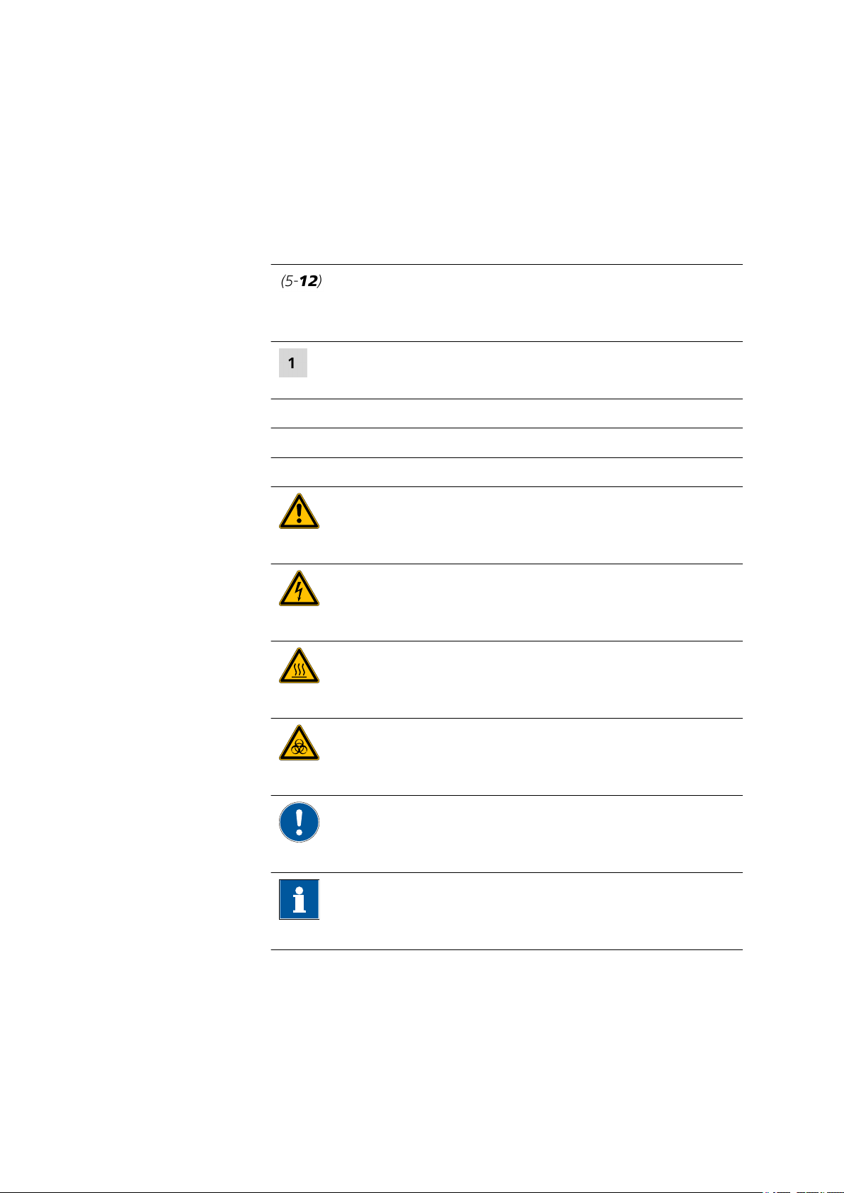
1.4 Symbols and conventions
The following symbols and formatting may appear in this documentation:
Cross-reference to figure legend
The first number refers to the figure number, the second to the instrument part in the figure.
Instruction step
Carry out these steps in the sequence shown.
Method Dialog text, parameter in the software
File ▶ New Menu or menu item
[Next] Button or key
1 Introduction
WARNING
This symbol draws attention to a possible life-threatening hazard or risk of injury.
WARNING
This symbol draws attention to a possible hazard due
to electrical current.
WARNING
This symbol draws attention to a possible hazard due
to heat or hot instrument parts.
WARNING
This symbol draws attention to a possible biological
hazard.
CAUTION
This symbol draws attention to possible damage to
instruments or instrument parts.
NOTE
930 Compact IC Flex ChS (2.930.1200)
This symbol highlights additional information and
tips.
■■■■■■■■
5
Page 14
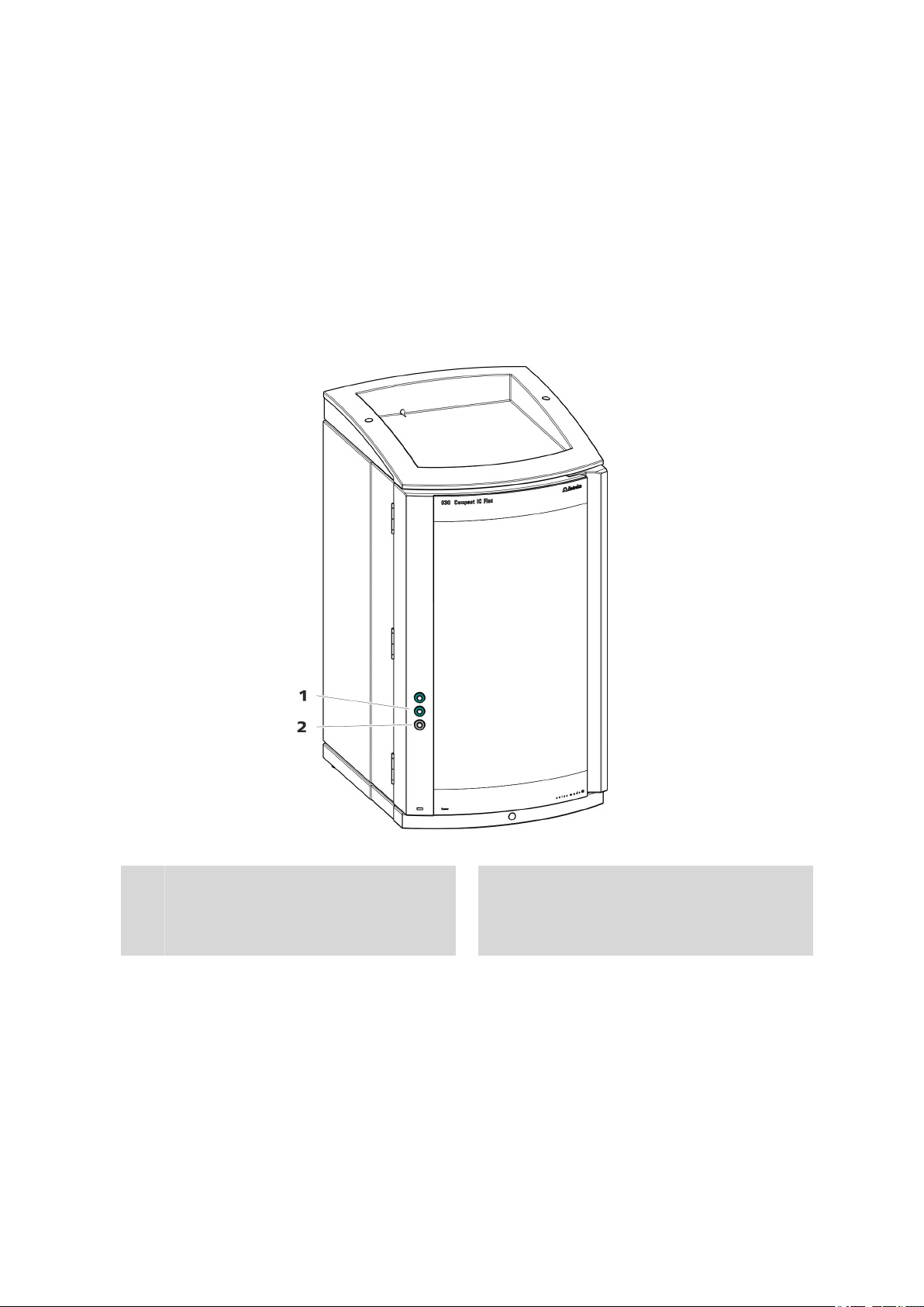
2.1 Front
2 Overview of the instrument
2.1 Front
■■■■■■■■■■■■■■■■■■■■■■
1
3
5
7
■■■■■■■■
6
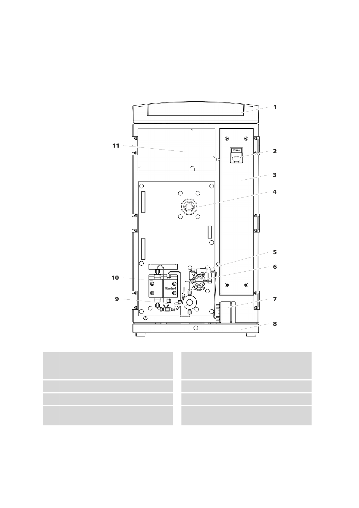
Figure 1 Front
Bottle holder
Offers space for the eluent bottle and additional accessories.
Column chamber
Inline filter
Pulsation absorber
Column holder
2
For hanging the separation column (iColumn). With column recognition.
Suppressor
4
Injection valve
6
Base tray
8
With leak sensor.
930 Compact IC Flex ChS (2.930.1200)
Page 15
■■■■■■■■■■■■■■■■■■■■■■
2 Overview of the instrument
Purge valve
9
For deaerating the high-pressure pump.
With rotary knob in the center and pressure
sensor.
Detector chamber
11
Offers space for an embedded detector and
additional accessories.
2.2 Rear
High-pressure pump
10
Pumps the eluent through the IC system.
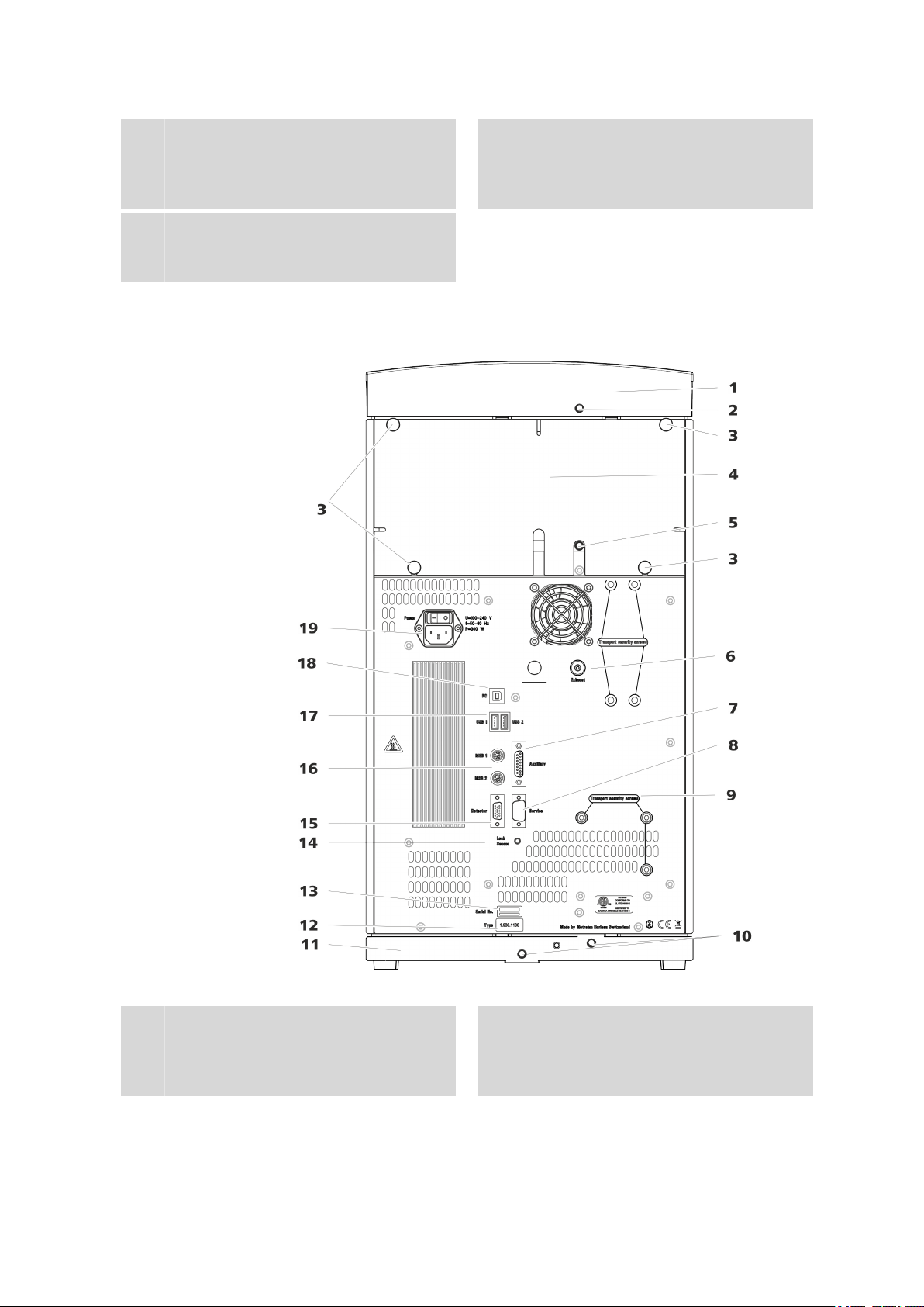
Figure 2
Bottle holder
1
930 Compact IC Flex ChS (2.930.1200)
Rear
Drainage tubing connection
2
For connecting the drainage tubing, which
guides escaped fluids away from the bottle
holder.
■■■■■■■■
7
Page 16

2.2 Rear
■■■■■■■■■■■■■■■■■■■■■■
Knurled screws
3
For fastening the removable back panel.
Drainage tubing connection
5
For connecting the drainage tubing, which
guides escaped fluids away from the detector chamber.
Auxiliary connection socket
7
For connecting an 891 Professional Analog
Out (2.891.0010).
Transport locking screws
9
For securing the high-pressure pump when
transporting the instrument.
Base tray
11
With leak sensor.
Serial number
13
Back panel
4
Removable. Enables access to the detector
chamber.
Exhaust opening
6
Labeled Exhaust. For extracting the air from
the vacuum chamber.
Service connection socket
8
For Metrohm service only.
Drainage tubing connections
10
For connecting two drainage tubings that
guide the escaped fluid to the leak sensor
and from there to the waste container.
Type plate
12
Leak sensor connection socket
14
Labeled Leak Sensor. For connecting the
leak sensor connection cable.
Detector connection socket
15
Labeled Detector. For connecting Metrohm
detectors.
USB connection sockets
17
Labeled USB 1 and USB 2. For connecting
USB devices.
Power socket
19
Power socket for connecting the power
cable and power switch for switching the
instrument on and off.
MSB connection sockets
16
Labeled MSB 1 and MSB 2. For connecting
MSB devices.
PC connection socket
18
For connecting the instrument to the computer with the USB cable (6.2151.020).
■■■■■■■■
8
930 Compact IC Flex ChS (2.930.1200)
Page 17
■■■■■■■■■■■■■■■■■■■■■■
2.3 Feed-throughs for capillaries and cables
Multiple openings are available for leading capillaries into the instrument
and for leading capillaries and cables out of the instrument:
■ Openings on the door
■ Openings on the back panel
■ Ducts between the instrument and the base tray as well as between
the instrument and the bottle holder (see Figure 5, page 11)
Openings on the door
2 Overview of the instrument
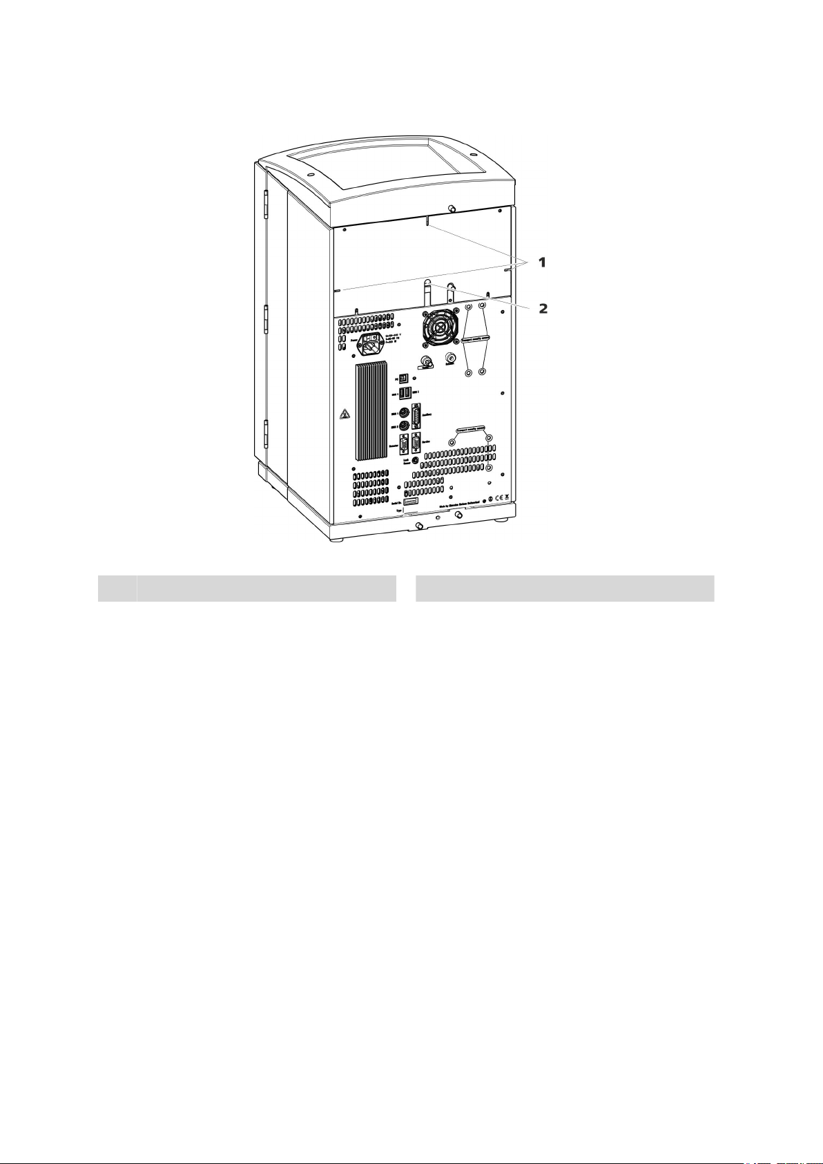
Figure 3
Luer connector
1
For connecting a capillary from inside and
for inserting a syringe (6.2816.020) from
outside. For manual sample injection.
An opening for up to 3 capillaries is located on the door of the instrument.
The two Luer connections above are not actually openings; the capillaries
are fastened to the Luer connection from within using PEEK pressure
screws. You can use a syringe to inject or draw out liquid from the outside.
930 Compact IC Flex ChS (2.930.1200)
Feed-throughs on the door
Opening for capillaries
2
For up to 3 capillaries.
■■■■■■■■
9
Page 18
2.3 Feed-throughs for capillaries and cables
Openings on the back panel
■■■■■■■■■■■■■■■■■■■■■■
Openings for capillaries
1
Figure 4 Openings for capillaries and cables
Openings for cables
2
The removable back panel is outfitted with openings through which capillaries and cables can be lead out of the detector chamber.
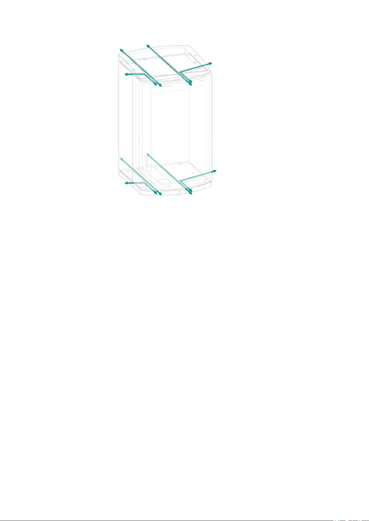
Ducts for capillaries
There are ducts for capillaries between the instrument and base tray as
well as between the instrument and the bottle holder. The capillaries can
be fed to the front of the instrument from both sides of the instrument
and from the front of the instrument to the back of the instrument.
■■■■■■■■
10
930 Compact IC Flex ChS (2.930.1200)
Page 19
■■■■■■■■■■■■■■■■■■■■■■
2 Overview of the instrument
Figure 5 Ducts for capillaries
930 Compact IC Flex ChS (2.930.1200)
■■■■■■■■
11
Page 20

3.1 Setting up the instrument
3 Installation
3.1 Setting up the instrument
3.1.1 Packaging
The instrument is supplied in highly protective special packaging together
with the separately packed accessories. Keep this packaging, as only this
ensures safe transportation of the instrument.
3.1.2 Checks
Immediately after receipt, check whether the shipment has arrived complete and without damage by comparing it with the delivery note.
3.1.3 Location
The instrument has been developed for operation indoors and may not be
used in explosive environments.
■■■■■■■■■■■■■■■■■■■■■■
Place the instrument in a location of the laboratory which is suitable for
operation, free of vibrations, protected from corrosive atmosphere, and
contamination by chemicals.
The instrument should be protected against excessive temperature fluctuations and direct sunlight.
3.2 Capillary connections in the IC system
Generally speaking, capillary connections between two components of an
IC system are made up of one connection capillary and two pressure
screws used to connect the capillary to the respective components.
Pressure screws
Three types of pressure screws are used in the IC system:
Number
6.2744.010 / 6.2744.014 Pressure screw On the injection valve
6.2744.070 Pressure screw, short High-pressure pump, purge
Designation Use
valve, inline filter, pulsation
absorber, separation columns
6.2744.090 Pressure screw, long MCS, sample degasser, 12port valve
Pressure screws are tightened and loosened by hand. A tool is not
needed.
■■■■■■■■
12
930 Compact IC Flex ChS (2.930.1200)
Page 21

■■■■■■■■■■■■■■■■■■■■■■
3 Installation
Also see: PEEK pressure screws video on the Internet http://ic-
help.metrohm.com/maintenance.php?chapter=1_2.
Connection capillaries
PEEK capillaries and PTFE capillaries are used in the IC system.
PEEK capillaries (polyetheretherketone)
PTFE capillaries
(poly(tetrafluoroethylene))
PEEK capillaries are temperature-resistant up to 100 °C, stable under pressure up to 400 bar (depending on the inner diameter), flexible, chemically
inert and have an extremely smooth surface. They can be readily cut down
to the desired length with the capillary cutter (6.2621.080).
Use:
■ PEEK capillaries with an inner diameter of 0.25 mm (6.1831.010) for
the entire high-pressure section.
■ PEEK capillaries with an inner diameter of 0.75 mm (6.1831.030) for
sample processing in the ultratrace range.
PTFE capillaries are transparent and enable visual tracing of the liquids to
be pumped. They are chemically inert, flexible and temperature-resistant
up to 80 °C. They can be readily cut down to the desired length with the
capillary cutter (6.2621.080).
Use:
PTFE capillaries (6.1803.0x0) are used for the low-pressure section.
■ PTFE capillaries with an inner diameter of 0.5 mm for sample process-
ing.
■ PTFE capillaries with an inner diameter of 0.97 mm for sample process-
ing and rinsing solutions (they are not necessarily included in the scope
of delivery of the instrument).
Capillary connections
If you work with an increased system pressure (> 15 MPa), capillaries
may slip out of the pressure screws.
To avoid this, we recommend degreasing the ends of the capillaries
before installing them.
Dampen a cloth with acetone and wipe off the ends of the capillaries
before connecting them with the pressure screws.
In order to achieve optimum analysis results, capillary connections in an IC
system must be absolutely tight and free of dead volume. Dead volume
occurs if two capillary ends connected to each other do not fit exactly,
thus allowing liquid to escape. There are two possible causes for this:
930 Compact IC Flex ChS (2.930.1200)
NOTE
■■■■■■■■
13
Page 22

3.2 Capillary connections in the IC system
■ The capillary ends do not have exactly flat edges.
■ The two capillary ends do not completely meet.
One prerequisite for dead-volume-free capillary connection is that both
capillary ends are cut exactly flat. Therefore we recommend cutting PEEK
capillaries only with a capillary cutter (6.2621.080).
Also see: Cutting capillaries video on the Internet http://ic-
help.metrohm.com/maintenance.php?chapter=1_1.
Creating dead-volume-free capillary connections
To create dead-volume-free capillary connections, proceed as follows:
1
2
3
4
■■■■■■■■■■■■■■■■■■■■■■
Wipe off the end of the capillary with a cloth dampened with acetone.
Slide the pressure screw over the capillary. Ensure that the capillary
protrudes 1 to 2 mm from the tip of the pressure screw.
Push the capillary into the connection or coupling as far as it will go
and hold it there.
Only then start turning the pressure screw.
Colored sleeves for PEEK capillaries
The enclosed set of varicolored sleeves for PEEK capillaries (6.2251.000)
serves to easily differentiate the various flows of liquid in the system
through color coding. Each capillary conveying a given liquid (e.g. eluent)
can be marked with sleeves of the same color.
Slide a sleeve of a selected color over a capillary and move it to an
1
easily visible position.
Heat the colored sleeve, such as with a hairdryer.
2
The colored sleeve shrinks and adapts to the shape of the capillary.
NOTE
In order to arrange capillaries more clearly, they can be bundled with
the spiral band (6.1815.010).
■■■■■■■■
14
930 Compact IC Flex ChS (2.930.1200)
Page 23
■■■■■■■■■■■■■■■■■■■■■■
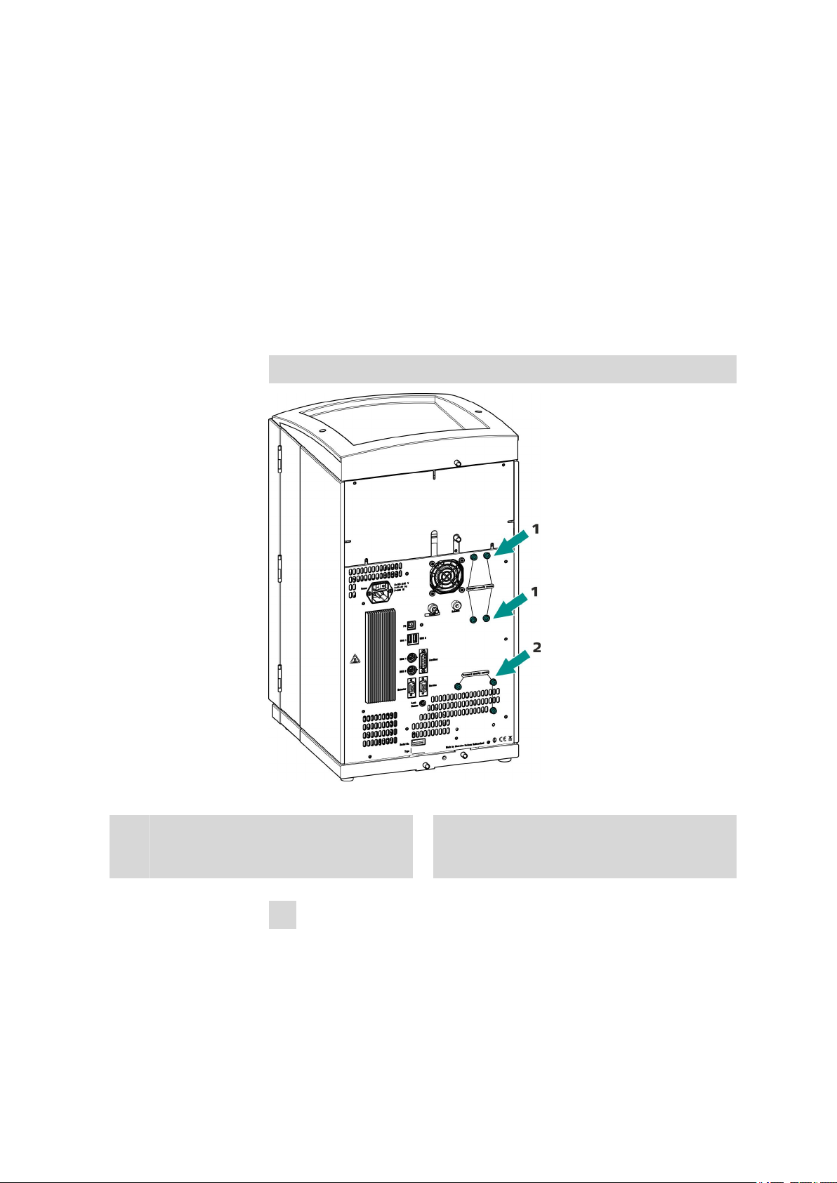
3.3 Removing transport locking screws
To avoid damage to the drives for the high-pressure pump and the vacuum pump during transport, the pumps are secured with transport locking screws. These are located at the rear of the instrument and labeled
with Transport security screws.
Remove these transport locking screws before the initial start-up.
Accessories For this step you need:
■ Hex key 4 mm (6.2621.030)
Remove the transport locking screws
3 Installation
Figure 6
Transport locking screws
1
For the vacuum pump. Only present if the
instrument has a degasser.
1
Store the transport locking screws in a safe place. Reinsert the transport
locking screws each time you transport the instrument a significant distance.
930 Compact IC Flex ChS (2.930.1200)
Removing the transport locking screws
Transport locking screws
2
For the high-pressure pump.
Remove all of the transport locking screws with the hex key.
■■■■■■■■
15
Page 24

3.4 Connecting the drainage tubing and leak sensor
■■■■■■■■■■■■■■■■■■■■■■
CAUTION
The pumps may be damaged if you transport the instrument without
inserting the transport locking screws.
3.4 Connecting the drainage tubing and leak sensor
The leak sensor detects leaking liquid that collects in the instrument's base
tray. Liquid that leaks in the bottle holder or in the detector chamber is
routed to the base tray using drainage tubing and is detected there.
If the leak sensor detects a leak in the IC system, the IC instrument is
switched off and a warning is output in the software.
The leak sensor functions properly only if the following preconditions are
met:
■ The drainage tubing is connected.
■ The leak sensor connection cable is inserted into the leak sensor con-
nection socket.
■ The 930 Compact IC Flex is switched on.
■ The leak sensor is switched to active in the software.
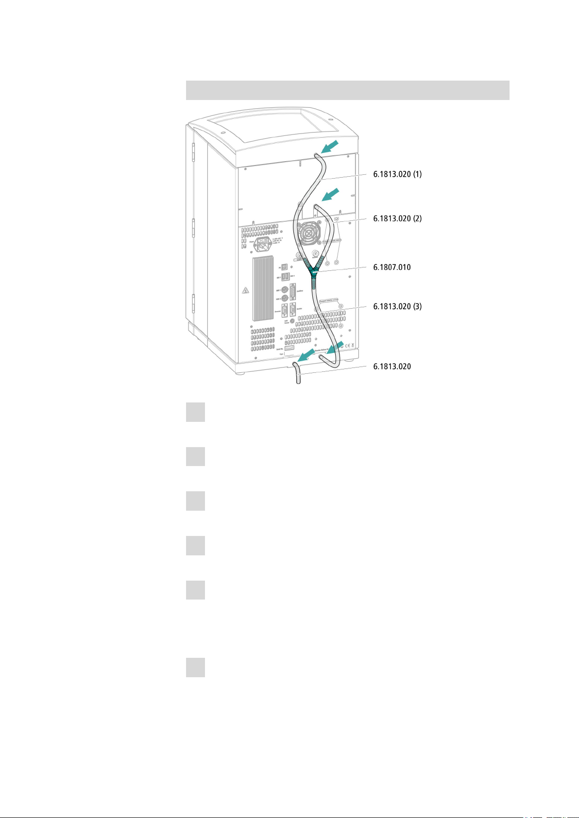
3.4.1 Installing the drainage tubing
Liquid that leaks in the bottle holder or detector chamber flows to the rear
of the instrument and is drained through openings on the bottle holder
and in the detector chamber. The drainage tubing has to be mounted at
these openings. This drainage tubing guides the leaking liquid to the base
tray where the leak sensor is located.
Accessories
For this step you need the following parts from the accessory kit: Vario/
Flex Basic (6.5000.000):
■ 2 × silicone tubing (6.1816.020)
■ Y connector (6.1807.010)
You also need scissors.
■■■■■■■■
16
930 Compact IC Flex ChS (2.930.1200)
Page 25
■■■■■■■■■■■■■■■■■■■■■■
3 Installation
Connecting the drainage tubing
Cut a piece of silicone tubing into three pieces using scissors: 2 ×
1
approx. 40 cm and 1 × 20 cm
Attach one end of the 40 cm long piece to the drainage tubing con-
2
nection on the bottle holder.
Attach one end of the 20 cm long piece to the drainage tubing con-
3
nection on the detector chamber.
Attach each of the loose ends of both pieces of silicone tubing to
4
one end of the Y connector.
Attach one end of the second 40 cm long piece to the third end of
5
the Y connector.
Attach the loose end to the right-side drainage tubing connection on
the base tray.
Attach one end of the second piece of silicone tubing to the left-side
6
drainage tubing connection on the base tray.
930 Compact IC Flex ChS (2.930.1200)
■■■■■■■■
17
Page 26
3.5 Connecting the eluent bottle
Route the loose end into a waste container.
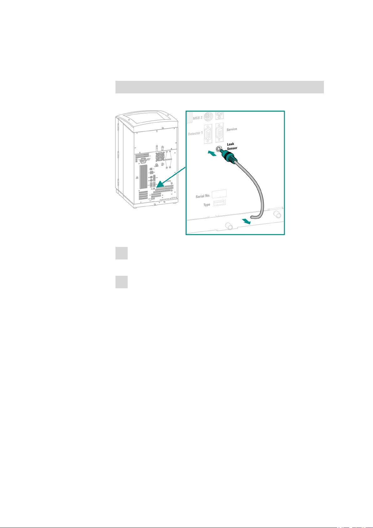
3.4.2 Connecting the leak sensor
Plugging in the leak sensor connection cable
The leak sensor connection cable is coiled up in the base tray.
■■■■■■■■■■■■■■■■■■■■■■
Pull the leak sensor connection cable out of the base tray as far as
1
needed.
Plug the plug for the leak sensor connection cable into the leak sen-
2
sor connection socket (labeled Leak Sensor).
3.5 Connecting the eluent bottle
The eluent is aspirated out of the eluent bottle via the eluent aspiration
tubing . The eluent aspiration tubing is installed on the input for the highpressure pump.
The tubing has to be be fed out of the instrument through a suitable
opening (see "Openings on the back panel", page 10) before the loose
end can be connected to the eluent bottle.
Accessories
For this step you need the following accessories:
These parts are part of the accessory kit Vario/Flex ONE (6.5000.010).
■ Eluent bottle (6.1608.070)
■■■■■■■■
18
930 Compact IC Flex ChS (2.930.1200)
Page 27
■■■■■■■■■■■■■■■■■■■■■■
3 Installation
■ The eluent bottle cap GL 45 accessory set (6.1602.160)
This accessory set contains the bottle cap, an M6 tubing nipple, an M8
tubing nipple, two O-rings and an M6 and M8 threaded stopper.
■ The tubing adapter for aspiration filter accessory set (6.2744.210)
This accessory set contains a filter holder, a clamping screw and tubing
weighting.
■ An aspiration filter (6.2821.090)
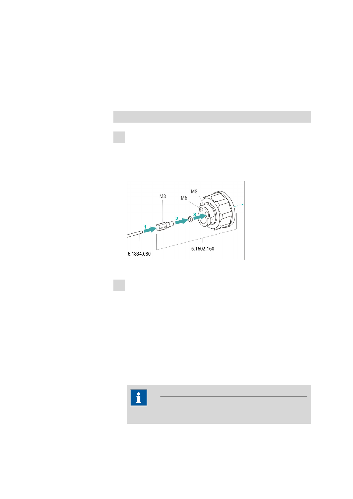
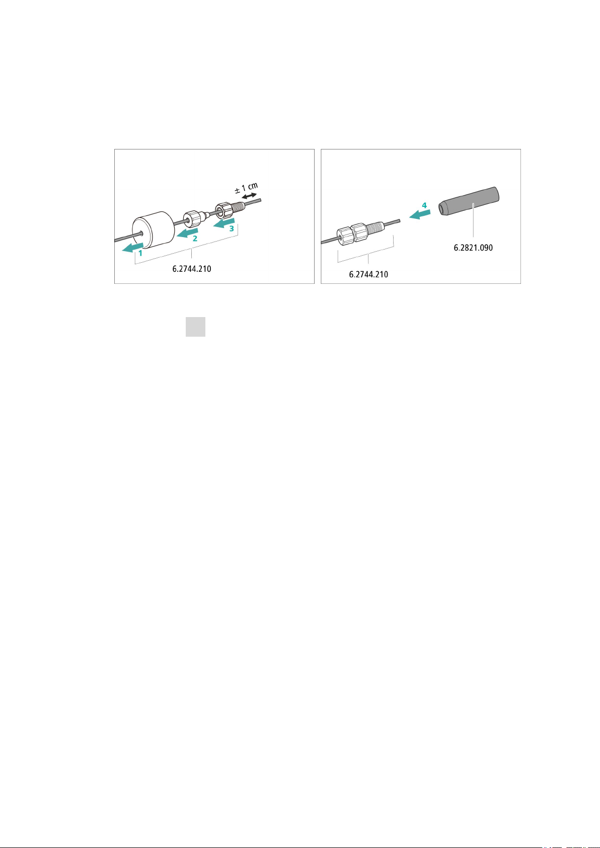
Connecting the eluent aspiration tubing
1
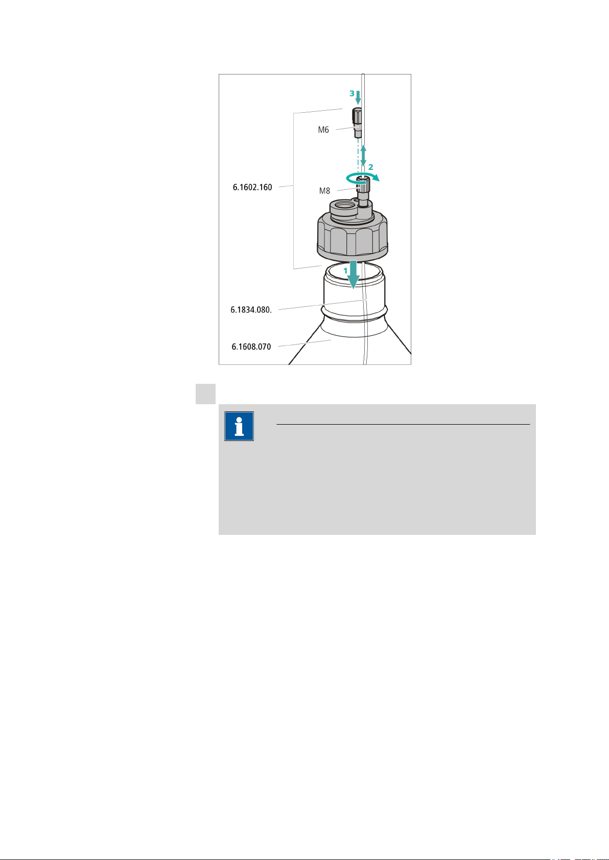
Installing the eluent bottle cap (6.1602.160)
■ Start by pushing the M8 tubing nipple onto the loose end of the
eluent aspiration tubing, followed by the O-ring.
■ Push the loose end of the eluent aspiration tubing through the
M8 opening of the bottle cap and screw it on for the time being.
Figure 7 Installing the eluent bottle cap
2
Mounting the tubing adapter and the aspiration filter
Install the parts of the tubing adapter for aspiration filter
(6.2744.210) accessory set:
■ Start by pushing the tubing weighting onto the loose end of the
eluent aspiration tubing.
■ Then push the clamping screw onto the loose end of the eluent
aspiration tubing.
■ Lastly, push the filter holder onto the loose end of the eluent aspi-
ration tubing and screw it onto the tubing nipple.
The end of the tubing should extend approximately 1 cm.
Installing the aspiration filter:
NOTE
Only handle the aspiration filter while wearing gloves.
930 Compact IC Flex ChS (2.930.1200)
■■■■■■■■
19
Page 28
3.5 Connecting the eluent bottle
■■■■■■■■■■■■■■■■■■■■■■
■ Place the loose end of the eluent aspiration tubing into the aspira-
tion filter.
The end of the tubing should reach approximately to the center of
the aspiration filter.
■ Tighten the aspiration filter to the filter holder.
Figure 8 Installing tubing weighting and aspiration filter
3
Installing the eluent bottle cap on the eluent bottle
■ Insert the eluent aspiration tubing into the eluent bottle
(6.1608.070).
■ Tighten the bottle cap on the eluent bottle.
■ Adjust the length of the eluent aspiration tubing so that the aspi-
ration filter is at the bottom of the eluent bottle. Then fasten it in
place using the M8 tubing nipple.
■ Seal the M6 opening on the bottle cap with the M6 threaded
stopper from the accessory set.
■■■■■■■■
20
930 Compact IC Flex ChS (2.930.1200)
Page 29
■■■■■■■■■■■■■■■■■■■■■■
3 Installation
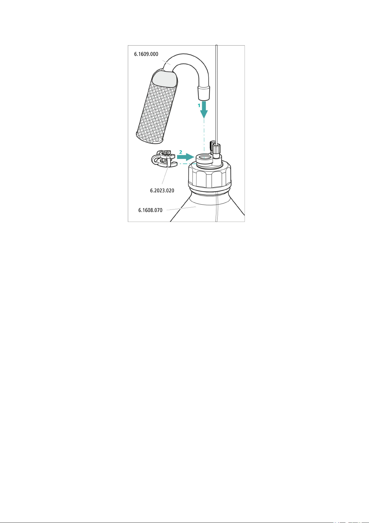
4
Mounting the adsorber tube
NOTE
Depending on the eluent used, the adsorber tube (6.1609.000)
must be filled differently:
■ For alkaline eluents or eluents with a low buffer capacity: first a
little cotton, then CO2 adsorber material.
■ For all other eluents: only cotton.
■ Remove the plastic cover from the large opening of the adsorber
tube. Fill the adsorber tube and close it again using the plastic
cover.
■ Insert the adsorber tube into the bottle cap's large opening. Fas-
ten it to the bottle cap using the SGJ clip (6.2023.020).
930 Compact IC Flex ChS (2.930.1200)
■■■■■■■■
21
Page 30
3.6 Installing the high-pressure pump
■■■■■■■■■■■■■■■■■■■■■■
3.6 Installing the high-pressure pump
The intelligent and low-pulsation high-pressure pump pumps the eluent
through the system. It is equipped with a chip where its technical specifications and "life history" (operating hours, service data, etc.) are saved.
The high-pressure pump consists of:
■ The pump head, which pumps the eluent through the system.
■ The purge valve used for bleeding the pump head.
■■■■■■■■
22
930 Compact IC Flex ChS (2.930.1200)
Page 31

■■■■■■■■■■■■■■■■■■■■■■
3 Installation
Figure 9 High-pressure pump with purge valve
Pump head
1
The high-pressure pump is completely connected. No installation work is
required.
3.7 Installing an inline filter
Inline filters reliably protect the separation column from potential contamination from the eluent. The small filter plates with 2 µm pore size can be
replaced quickly and easily. They remove particles from the solutions, such
as bacteria and algae.
An inline filter (6.2821.120) is installed between the purge valve and the
pulsation absorber as protection against particles.
Purge valve
2
930 Compact IC Flex ChS (2.930.1200)
■■■■■■■■
23
Page 32

3.8 Installing the pulsation absorber
Figure 10 Inline filter
■■■■■■■■■■■■■■■■■■■■■■
Input capillary
1
Connected to the purge valve.
Output capillary
2
Connected to the pulsation absorber.
The inline filter is completely connected. No installation work is required.
3.8 Installing the pulsation absorber
The pulsation absorber is installed between the high-pressure pump and
the injection valve. It protects the separation column from damage caused
by pressure fluctuations such as those when switching the injection valve,
and reduces interfering pulsations during highly sensitive measurements.
■■■■■■■■
24
Figure 11
Connection capillary
1
Connection to inline filter.
Pulsation absorber (6.2620.150)
3
Connection capillary
5
Connection to injection valve.
Pulsation absorber
2
4
PEEK pressure screws, short
(6.2744.070)
Holder for pulsation absorber
930 Compact IC Flex ChS (2.930.1200)
Page 33

■■■■■■■■■■■■■■■■■■■■■■
The pulsation absorber is completely connected. No installation work is
required.
3.9 Injection valve
The injection valve connects the eluent path to the sample path. By a
quick and precise switching of the valve a defined quantity of sample solution is injected and flushed to the separation column with the eluent.
The quantity of injected sample solution is determined either by the volume of the sample loop or by an 800 Dosino, if Metrohm's intelligent partial loop injection techniques (MiPT) are being used. For these techniques,
a large sample loop is used, but it is only filled part way.
The choice of sample loop depends on the application. The following
sample loops are normally used:
3 Installation
Table 1
Which sample loop do I need?
Cation determination 10 µL
Anion determination with suppression 20 µL
Anion determination without suppression 100 µL
MiPT 250 µL
The injection valve is completely connected. No installation work is
required.
Optional: Exchanging the sample loop
The sample loop can be replaced to match the application (see Table 1,
page 25).
NOTE
Only use PEEK pressure screws (6.2744.010) to connect capillaries and
the sample loop to the injection valve.
930 Compact IC Flex ChS (2.930.1200)
■■■■■■■■
25
Page 34

3.9 Injection valve
■■■■■■■■■■■■■■■■■■■■■■
Figure 12 Exchanging the sample loop
Pressure screw
1
Fastened to Port 6.
Pressure screw
3
Fastened to Port 3.
Sample loop
2
Exchanging the sample loop
1
Removing the existing sample loop
■ Unscrew the pressure screws (6.2744.010) at Port 3 and Port 6.
■ Remove the sample loop.
2
Installing a new sample loop
■ Fasten one end of the sample loop to Port 3 using a PEEK pres-
sure screw (6.2744.010).
■ Use the second PEEK pressure screw (6.2744.010) to fasten the
other end of the sample loop to Port 6.
■■■■■■■■
26
930 Compact IC Flex ChS (2.930.1200)
Page 35

■■■■■■■■■■■■■■■■■■■■■■
3.10 Suppressor
The suppressor drive of the 930 Compact IC Flex can hold various rotors.
The large rotors such as the SPM Rotor A (6.2835.000) and the MSM-HC
Rotor A (6.2842.000) can be inserted directly.
Small rotors like the MSM Rotor A (6.2832.000) and the MSM-LC Rotor A
(6.2844.000) must first be fitted into the adapter (6.2842.020) which can
then be inserted into the suppressor housing.
A connecting piece (6.2835.010) is used for all rotors for connecting the
suppressor to the IC system.
3 Installation
The instruments are supplied without rotor and without adapter.
The suitable rotor and the adapter, if required, must be ordered separately.
3.10.1 Inserting the rotors
Accessories
For this step you need the following accessories:
■ For the suppression: MSM Rotor A (6.2832.000) or MSM-HC Rotor A
(6.2842.000) or MSM-LC Rotor A (6.2844.000)
■ Optional: Adapter (6.2842.020)
■ Connecting piece (6.2835.010)
Large rotors can be directly inserted into the rotor housing.
NOTE
930 Compact IC Flex ChS (2.930.1200)
■■■■■■■■
27
Page 36

3.10 Suppressor
■■■■■■■■■■■■■■■■■■■■■■
CAUTION
The rotor may be destroyed during start-up if not inserted correctly.
Therefore, follow the following instructions exactly.
Inserting large rotors
■■■■■■■■
28
1
Removing the union nut
Loosen the union nut and remove it.
2
Inserting the rotor
■ Clean the sealing surface of the rotor with ethanol using a lint-
free cloth.
■ Insert the rotor into the suppressor drive so that the tubing con-
nections on the rear of the rotor fit into the corresponding
recesses inside the suppressor drive and one of the three holes of
the rotor is visible from below in the slot of the suppressor drive.
930 Compact IC Flex ChS (2.930.1200)
Page 37

■■■■■■■■■■■■■■■■■■■■■■
NOTE
The rotor's sealing surface is approximately 4 mm inside the suppressor drive if the rotor is inserted correctly.
If this is not the case, then the rotor has to be moved into the correct position from below using a sharp object (e.g. a screwdriver).
3
Inserting the connecting piece
■ Clean the sealing surface of the connecting piece with ethanol
using a lint-free cloth.
■ Insert the connecting piece into the suppressor drive so that con-
nector 1 is on top and the three pins of the connecting piece fit
into the corresponding recesses on the suppressor drive.
4
Attaching the union nut
Tighten the union nut on the thread of the suppressor drive by hand
(do not use any tools).
3 Installation
Inserting small rotors
You need the adapter (6.2842.020) in order to insert a small rotor into the
suppressor drive.
1
Inserting the rotor into the adapter
CAUTION
An incorrectly inserted rotor can be destroyed during start-up.
930 Compact IC Flex ChS (2.930.1200)
■ Clean the sealing surface of the rotor with ethanol using a lint-
free cloth.
■■■■■■■■
29
Page 38

3.10 Suppressor
■ Insert the rotor into the adapter so that the tubing connections
on the rear of the rotor fit into the corresponding recesses inside
the adapter and one of the three holes of the rotor is visible in the
slot of the adapter.
2
Inserting the adapter
Insert the adapter into the suppressor drive just like a large rotor (see
"Inserting large rotors", page 28).
3.10.2 Connecting the suppressor
The three inputs and outputs of the suppressor units, numbered with 1, 2
and 3 on the connecting piece, each have 2 fixed mounted PTFE capillaries.
■■■■■■■■■■■■■■■■■■■■■■
■■■■■■■■
30
Figure 13
out
1
Output capillary for the eluent.
regenerant
3
Input capillary for the regeneration solution.
waste rins.
5
Output capillary for the rinsing solution; to
the waste container.
Suppressor – connection capillaries
in
2
Input capillary for the eluent.
waste reg.
4
Output capillary for the regeneration solution; to the waste container.
rinsing solution
6
Input capillary for the rinsing solution.
930 Compact IC Flex ChS (2.930.1200)
Page 39

■■■■■■■■■■■■■■■■■■■■■■
3 Installation
Recommended installation
Alternative installation
Accessories
Installing bottles with auxiliary solutions
To connect the bottles of the auxiliary solutions, you will need the following accessories:
■ Accessories from IC equipment: Dosino Regeneration (6.5330.190)
930 Compact IC Flex ChS (2.930.1200)
■■■■■■■■
31
Page 40

3.10 Suppressor
3.10.2.1 Installing the eluent path
The eluent path is connected with the capillaries in and out.
■■■■■■■■■■■■■■■■■■■■■■
Connect the capillary labeled with in with the output of the separa-
1
tion column using a short pressure screw (6.2744.070).
Connect the capillary labeled with out to the detector input capillary
2
using one (6.2744.040) coupling and two (6.27474.070) pressure
screws (see manual of the detector).
3.10.2.2 Connecting the regeneration solution
The regeneration solution is connected to the regenerant capillary.
Connecting the regeneration solution to the Dosino
For this step you need the following accessories:
■ Dosino (2.800.0010)
■ Dosing unit 50 mL (6.3032.250)
■ Accessory kit: Flex/Vario: ChS (6.5000.030)
■ IC equipment: Dosino Regeneration (6.5330.190)
■■■■■■■■
32
930 Compact IC Flex ChS (2.930.1200)
Page 41

■■■■■■■■■■■■■■■■■■■■■■
3 Installation
Fasten the capillary labeled regenerant to the outlet of the inline filter
1
(6.2821.120) using a pressure screw (6.2744.070).
Use a pressure screw (6.2744.070) to fasten one end of the PEEK
2
capillary (6.1803.030) to the inlet of the inline filter.
Use a pressure screw (6.2744.070) and an adapter (6.2744.080) to
3
fasten the other end of the PEEK capillary to Port 1 of the Dosino.
Connect the FEP tubing (6.1805.120) from the bottle with the regen-
4
eration solution to Port 2 of the Dosino.
3.10.2.3 Connecting the rinsing solution
There are 2 options for rinsing the suppressor:
■ Rinsing solution via STREAM (recommended)
Use the eluent from the conductivity detector as a rinsing solution.
■ Rinsing solution via Dosino
Prepare the rinsing solution in its own bottle and transport with a Dosino.
The rinsing solution is connected to the rinsing solution capillary.
930 Compact IC Flex ChS (2.930.1200)
■■■■■■■■
33
Page 42

3.10 Suppressor
■■■■■■■■■■■■■■■■■■■■■■
Connecting the rinsing solution inlet with STREAM
Connect the detector output capillary and the capillary labeled rins-
1
ing solution to each other using a coupling (6.2744.040) and two
pressure screws (6.2744.070).
Connecting the rinsing solution inlet to the Dosino
The rinsing solution capillary can be connected to the Dosino to which the
regenerant capillary is already connected.
For this step you need the following accessories:
■ Accessory kit: Flex/Vario: ChS (6.5000.030)
■ IC equipment: Dosino Regeneration (6.5330.190)
Fasten the capillary labeled rinsing solution to the outlet of an inline
1
filter (6.2821.120) using a pressure screw (6.2744.070).
Use a pressure screw (6.2744.070) to fasten one end of the PEEK
2
capillary (6.1803.030) to the inlet of the inline filter.
Use a pressure screw (6.2744.070) and an adapter (6.2744.080) to
3
fasten the other end of the PEEK capillary to Port 1 of the Dosino.
■■■■■■■■
34
930 Compact IC Flex ChS (2.930.1200)
Page 43

■■■■■■■■■■■■■■■■■■■■■■
Connect the FEP tubing (6.1805.120) from the bottle with the rinsing
4
solution with the adapter Dosino Port 4/M6 to the Port 4 of the Dosino.
If you would like to use a separate Dosino for the rinsing solution, you will
need the following additional accessories:
■ Dosino (2.800.0010)
■ Dosing unit 50 mL (6.3032.250)
■ Accessory kit: Flex/Vario: ChS (6.5000.030)
■ IC equipment: Dosino Regeneration (6.5330.190)
Connect the rinsing solution capillary with the Dosino and the bottle with
the rinsing solution as described in chapter Connecting the regeneration
solution to the Dosino, page 32.
3.11 Installing the detector
The 930 Compact IC Flex provides enough space for two detectors and
additional accessories in the detector chamber. The detectors are available
as accessories and are supplied with separate manuals.
3 Installation
Accessories
Placing the detector in the instrument
Follow the instructions in the chapter Inserting the detector in the manual
for the detector.
Connecting the detector to the eluent path
For this step you need the following accessories:
■ Coupling (6.2744.040)
■ 2 × pressure screw (6.2744.010)
Connect the out capillary of the suppressor and the detector input
1
capillary to one another using a coupling (6.2744.040) and two short
pressure screws (6.2744.070).
930 Compact IC Flex ChS (2.930.1200)
■■■■■■■■
35
Page 44

3.12 Connecting the instrument to a computer
■■■■■■■■■■■■■■■■■■■■■■
3.12 Connecting the instrument to a computer
NOTE
The instrument must be switched off when being connected to a computer.
Accessories For this step you need the following accessories:
■ USB connecting cable (6.2151.020)
■ USB connection cable (6.2151.020) from the accessory kit: Vario/Flex
Basic (6.5000.000)
Connecting the USB cable
■■■■■■■■
36
Insert the USB cable into the computer connection socket on the rear
1
of the instrument.
Insert the other end into a USB port on the computer.
2
930 Compact IC Flex ChS (2.930.1200)
Page 45

■■■■■■■■■■■■■■■■■■■■■■
3.13 Connecting the instrument to the power supply
WARNING
The power supply unit must not get wet. Protect it from liquids.
The power supply cable is three-core and provided with a plug with
grounding. If another plug has to be mounted, the yellow/green conductor (IEC standard) must be connected to the protective ground (protection
class I).
3 Installation
Accessories
For this step you need the following accessories:
■ For Switzerland, …: Power supply cable with IEC 60320 line socket,
type C13, with SEV 1011 plug, type 12 (6.2122.020), 1.5 m
■ For Germany, …: Power supply cable with IEC 60320 line socket, type
C13, with CEE 7 plug, type VII (6.2122.040), 1.5 m
■ For the USA, …: Power supply cable with IEC 60320 line socket, type
C13, with NEMA 5-15 plug, type 498 (6.2122.070), 1.5 m
Connecting the power supply cable
1
2
930 Compact IC Flex ChS (2.930.1200)
Inserting the power supply cable
■ Insert the power supply cable into the instrument's power socket.
■ Connect the power supply cable to the power supply.
Switching on the instrument
Switch on the instrument using the power switch.
■■■■■■■■
37
Page 46

3.14 Initial start-up
After being switched on, the LED on the front of the instrument
flashes. The instrument conducts a system test and establishes a connection to the software. Once the system test is complete and the
connection to the software has been established, the LED lights up
continuously.
3.14 Initial start-up
Even before the guard column and separation column are installed, the
entire system has to be completely rinsed with eluent for the first time.
Rinsing the IC system
The guard column and separation column must not be installed for the
initial start-up.
■■■■■■■■■■■■■■■■■■■■■■
CAUTION
Make sure that a coupling (6.2744.040) is being used instead of the
columns.
1
Preparing the software
■ Start the MagIC Net computer program.
■ Open the Equilibration tab in MagIC Net: Work-
place ▶ Run ▶ Equilibration.
■ Select (or create) a suitable method.
Also see: MagIC Net tutorial and online help.
2
Preparing the instrument
■ Ensure that the eluent aspiration tubing is immersed in the eluent
and there is enough eluent in the eluent bottle.
■ STREAM method (recommended): Ensure that the aspiration tub-
ing for the regeneration solution is immersed in the solution and
that there is enough solution; also check that the detector output
capillary is connected to the suppressor's input capillary for rinsing
solution (labeled rinsing solution).
Alternatively, if two bottles are being used for rinsing and regeneration: Ensure that the aspiration tubings for the auxiliary solutions (regeneration solution and rinsing solution) are immersed in
the respective solutions and that there is enough solution in both
bottles.
■ Switch on the instrument.
■■■■■■■■
38
930 Compact IC Flex ChS (2.930.1200)
Page 47

■■■■■■■■■■■■■■■■■■■■■■
MagIC Net detects the instrument and all of its modules.
3
Starting equilibration
■ Start the equilibration in MagIC Net: Workplace ▶ Run ▶ Equi-
libration ▶ Start HW.
4
Deaerating the high-pressure pump
3 Installation
5
930 Compact IC Flex ChS (2.930.1200)
■ Push the end of the purging needle (6.2816.040) over the end of
the deaerating capillary on the purge valve.
■ Insert the syringe (6.2816.020) in the Luer connector of the purg-
ing needle.
■ Open the purge valve using the rotary knob (approx. ½ turn).
■ Switch on the high-pressure pump in MagIC Net.
■ Use the syringe to aspirate eluent until there are no more air bub-
bles in the aspirated eluent.
■ Switch off the high-pressure pump in MagIC Net.
■ Seal the purge valve using the rotary knob.
■ Remove the syringe from the purging needle.
■ Pull the purging needle out of the deaerating capillary.
Rinsing the instrument without columns
■ Rinse the instrument (without columns) with eluent for 5 minutes.
■■■■■■■■
39
Page 48

3.15 Connecting and rinsing the guard column
■■■■■■■■■■■■■■■■■■■■■■
3.15 Connecting and rinsing the guard column
Guard columns protect the separation column and substantially increase
its service life. Guard columns available from Metrohm are either actual
guard columns or what are known as guard column cartridges that can be
used together with a cartridge holder. The process for installing a guard
column cartridge in the associated holder is described in the leaflet for the
guard column.
NOTE
Metrohm recommends working with guard columns at all times. They
protect the separation column and can be replaced regularly as needed.
NOTE
Information regarding which guard column is suitable for your separation column can be found in the Metrohm IC Column Program
(which is available from your Metrohm representative), the leaflet provided along with your separation column, the product information about
the separation column at http://www.metrohm.com (Ion Chromatography product area), or obtained directly from your representative.
CAUTION
New guard columns are filled with solution and sealed with stoppers or
caps on both sides.
Before inserting the guard column, ensure that this solution can be
mixed with the eluent being used (follow information from the manufacturer).
NOTE
The guard column may not be connected until after the instrument has
already been put into operation once (see Chapter 3.14, page 38). The
guard column and separation column have to be replaced by a coupling
(6.2744.040) until then.
Accessories
■■■■■■■■
40
For this step you need the following accessories:
930 Compact IC Flex ChS (2.930.1200)
Page 49

■■■■■■■■■■■■■■■■■■■■■■
■ Guard column (suitable for the separation column)
Connecting the guard column
1
Removing the coupling
Remove the coupling installed between the column input capillary
and the column output capillary for the initial start-up.
2
Preparing the guard column
■ Remove the stopper and the sealing cap from the guard column.
3
Connecting the guard column
3 Installation
CAUTION
When inserting the guard column, ensure that it is inserted correctly based on the marked flow direction (if specified).
■ Fasten the input of the guard column to the column input capil-
lary using a short pressure screw (6.2744.070).
■ Optional: In case the guard column is connected to the separation
column using a provided a connection capillary, fasten the connection capillary to the guard column's output using the pressure
screw also provided.
Rinsing the guard column
1
Rinsing the guard column
■ Place a beaker under the guard column's output.
930 Compact IC Flex ChS (2.930.1200)
■■■■■■■■
41
Page 50

3.16 Connecting the separation column
■ Start manual control in MagIC Net and select the high-pressure
pump: Manual ▶ Manual control ▶ Pump
– Flow: in accordance with column leaflet
– On
■ Rinse the guard column with eluent for approx. 5 minutes.
■ Use manual control in MagIC Net to stop the high-pressure pump
again: Off.
3.16 Connecting the separation column
The intelligent separation column (iColumn) is the heart of the ion chromatographic analysis. It separates different components according to their
interactions with the column. Metrohm separation columns are equipped
with a chip where their technical specifications and history (start-up, operating hours, etc) are stored.
NOTE
■■■■■■■■■■■■■■■■■■■■■■
Information regarding which separation column is suitable for your
application can be found in the Metrohm IC Column Program, the
product information for your separation column at http://
www.metrohm.com (Ion Chromatography product area) or obtained
directly from your representative.
You can find the separation columns and guard columns currently available from Metrohm in the Metrohm IC Column Program or on the Internet at http://www.metrohm.com in the Ion Chromatography product
area. A test chromatogram and a leaflet are provided along with each column. You can find detailed information on special IC applications in the
corresponding "Application Bulletins" or "Application Notes", which
are available on the Internet at http://www.metrohm.com in the Applications area or free of charge upon request from your responsible Metrohm
representative.
CAUTION
New separation columns are filled with solution and sealed with stoppers on both sides. Before inserting the column, ensure that this solution can be mixed with the eluent being used (follow information from
the manufacturer).
■■■■■■■■
42
930 Compact IC Flex ChS (2.930.1200)
Page 51

■■■■■■■■■■■■■■■■■■■■■■
3 Installation
NOTE
The separation column may not be connected until after the instrument
has already been put into operation once (see Chapter 3.14, page 38).
The guard column and separation column have to be replaced by a
coupling (6.2744.040) until then.
930 Compact IC Flex ChS (2.930.1200)
■■■■■■■■
43
Page 52

3.16 Connecting the separation column
Connecting the separation column
1
2
3
4
■■■■■■■■■■■■■■■■■■■■■■
Removing the stoppers
CAUTION
When inserting the column, ensure that it is inserted correctly
based on the marked flow direction.
■ Remove the stoppers from the separation column.
Installing the input of the separation column
There are 3 possibilities:
■ Attaching the bottom end of the separation column directly to
the guard column.
or
■ If the guard column is connected to the separation column using
a provided connection capillary, connect the bottom end of the
separation column to the guard column's output capillary using
the provided PEEK pressure screw (6.2744.070).
or
■ If no guard column is used (not recommended), connect the col-
umn input capillary to the input of the separation column using a
short pressure screw (6.2744.070).
Rinsing the separation column
■ Place a beaker under the separation column's outlet.
■ Start manual control in MagIC Net and select the high-pressure
pump: Manual ▶ Manual control ▶ Pump
– Flow: in accordance with column leaflet
– On
■ Rinse the separation column with eluent for approximately 10
minutes.
■ Use manual control in MagIC Net to stop the high-pressure pump
again: Off.
Removing the coupling
■ Remove the coupling (6.2744.040) from the column output capil-
lary.
■■■■■■■■
44
930 Compact IC Flex ChS (2.930.1200)
Page 53

■■■■■■■■■■■■■■■■■■■■■■
5
Installing the output of the separation column
■ Fasten the column output capillary to the upper end of the sepa-
6
Inserting the separation column
■ Insert the separation column with chip into the column holder
The separation column is now detected by MagIC Net.
3.17 Conditioning
After installation, after each time the instrument is switched on and after
each time the eluent is changed, the system has to be conditioned with
eluent long enough that a stable baseline is attained.
3 Installation
ration column using a PEEK pressure screw (6.2744.070).
until you hear it snap in place.
NOTE
The conditioning time can lengthen considerably after changing the
eluent.
Conditioning the system
1
Preparing the software
CAUTION
Ensure that the configured flow is not higher than the flow permitted for the corresponding column (refer to the column leaflet and
the chip data record).
■ Start the MagIC Net computer program.
■ Open the Equilibration tab in MagIC Net: Work-
place ▶ Run ▶ Equilibration.
■ Select (or create) a suitable method.
Also see: MagIC Net tutorial and online help.
2
Preparing the instrument
■ Ensure that the column is inserted correctly in relation to the flow
direction marked on the sticker (arrow has to point in the direction of flow).
930 Compact IC Flex ChS (2.930.1200)
■■■■■■■■
45
Page 54

3.17 Conditioning
■■■■■■■■■■■■■■■■■■■■■■
■ Ensure that the eluent aspiration tubing is immersed in the eluent
and there is enough eluent in the eluent bottle.
3
Starting equilibration
■ Start the equilibration in MagIC Net: Workplace ▶ Run ▶ Equi-
libration ▶ Start HW.
■ Visually inspect whether all capillaries and their connections from
the high-pressure pump to the detector are leak-tight. If eluent is
leaking out anywhere, tighten the corresponding pressure screw
further, or loosen the pressure screw, check the end of the capillary and shorten it using the capillary cutter if necessary and
retighten the pressure screw.
4
Conditioning the system
Rinse the system with eluent until the required stability of the baseline is attained (normally 30 minutes).
The instrument is now ready for measuring samples.
■■■■■■■■
46
930 Compact IC Flex ChS (2.930.1200)
Page 55

■■■■■■■■■■■■■■■■■■■■■■
4 Operation
4 Operation
The 930 Compact IC Flex ChS is operated solely using the MagIC Net software. You can find information on operating the software in the tutorial
for MagIC Net or in the online help.
930 Compact IC Flex ChS (2.930.1200)
■■■■■■■■
47
Page 56

5.1 IC system
5 Operation and maintenance
5.1 IC system
5.1.1 Operation
CAUTION
In order to avoid disruptive temperature influences, the entire system
including the eluent bottle must be protected from direct sunlight.
5.1.2 Care
The instrument requires appropriate care. Excess contamination of the
instrument may result in functional disruptions and a reduction in the lifetime of the sturdy mechanical and electronic components.
■■■■■■■■■■■■■■■■■■■■■■
The instrument must be cleaned immediately if chemicals or solutions are
spilled on it. In particular, the plug connections (particularly the power
plug) have to be protected from contamination.
CAUTION
The instrument has been designed so that liquid is largely prevented
from being able to get inside the instrument. However, unplug the
power plug immediately if you suspect that corrosive media have gotten inside the instrument. This is the only way to prevent extreme damage to the instrument electronics. Notify Metrohm Service.
WARNING
Untrained personnel may not open the instrument's housing.
5.1.3 Maintenance by Metrohm Service
Maintenance of the instrument is best carried out as part of annual service
performed by specialist personnel from Metrohm. A shorter maintenance
interval is recommended if you are frequently working with caustic and
corrosive chemicals. Metrohm Service offers every form of technical advice
for maintenance and service of all Metrohm instruments.
■■■■■■■■
48
930 Compact IC Flex ChS (2.930.1200)
Page 57

■■■■■■■■■■■■■■■■■■■■■■
5.1.4 Shutting down and starting back up
If the instrument is not used for a long period, the whole IC system (without separation column) must be rinsed to be free of salts using methanol/
ultrapure water (1:4). This prevents eluent salts from crystallizing and then
causing damage.
Rinsing the IC system to be free of salts
In the software, stop the hardware and wait until the pressure in the
1
high-pressure pump has dissipated.
Remove the guard column and the separation column from the elu-
2
ent path. Connect the connection capillaries directly with each other
using a coupling (6.2744.040).
Rinse the IC system for 15 minutes with methanol/ultrapure water
3
(1:4).
Optional: Only if the IC system is equipped with a ChS plug-in or a
4
SeS plug-in.
5 Operation and maintenance
In the software, switch the suppressor twice during the rinsing process (STEP command).
Optional: Only if the IC system is equipped with a ChS/PP plug-in or a
5
SeS/PP plug-in.
Rinse the two pieces of pump tubing for the peristaltic pump with
water for 5 minutes at level 3. Finish by releasing the peristaltic
pump's contact pressure.
Putting the IC system back into operation
Check that a coupling (6.2744.040) is installed in place of the guard
1
column and the separation column.
Rinse the IC system with eluent for 15 minutes.
2
Remove the coupling and install the guard column and the separa-
3
tion column and (see Chapter 3.16, page 42).
930 Compact IC Flex ChS (2.930.1200)
■■■■■■■■
49
Page 58

5.2 Capillary connections
5.2 Capillary connections
All connections between injection valve, separation column and detector
must be as short as possible, have a low dead volume and be completely
leak-tight.
The PEEK capillary downstream of the detector must be free of blockages.
Only use PEEK capillaries with an inner diameter of 0.25 mm in the highpressure section between the high-pressure pump and the detector.
5.3 Servicing the door
CAUTION
The door is made of PMMA (poly(methyl methacrylate)). It must never
be cleaned with abrasive media or solvents.
■■■■■■■■■■■■■■■■■■■■■■
CAUTION
Never hold the instrument by the door when lifting it. Only hold the
instrument by the housing.
5.4 Handling the eluent
Careful handling of the eluent ensures stable analysis results. Keep the following general measures in mind when handling the eluent:
■ The supply bottle with the eluent must be connected as indicated in
chapter 3.5, page 18. This is particularly important for eluents with volatile solvents (such as acetone).
■ Avoid condensation in the eluent bottle. Drop formation can change
the concentration ratio in the eluent.
■ In the case of very sensitive measurements, we recommend that the
eluent be stirred constantly with a magnetic stirrer (e. g. the
2.801.0010 with 6.2070.000).
■ To protect the IC system from foreign particles, we recommend aspi-
rating the eluent via an aspiration filter (see Chapter 3.5, page 18)
(6.2821.090). This aspiration filter has to be replaced as soon as it
turns yellow but at least every 3 months.
■■■■■■■■
50
930 Compact IC Flex ChS (2.930.1200)
Page 59

■■■■■■■■■■■■■■■■■■■■■■
5.4.1 Manufacturing eluent
Chemicals used for manufacturing eluents must have a purity grade of at
least "p.a." They may be diluted only by using ultrapure water (resistance
> 18.2 MΩ*cm). (These specifications apply generally for all reagents used
in ion chromatography).
Newly manufactured eluents always have to be microfiltered (0.45 µm filter).
The composition of the eluent plays a critical role in chromatographic analysis:
Concentration An increase in the concentration generally leads
pH pH changes lead to shifts in dissociation equili-
Organic solvents Adding organic solvents (such as methanol, ace-
5 Operation and maintenance
to shorter retention times and faster separation,
but also to a higher background conductivity signal.
bria and thus to changes in retention times.
tone or acetonitrile) to a watery eluent generally
speeds up lipophilic ions.
5.4.2 Changing the eluent
Ensure that no precipitates can form when changing the eluent. Immediately successive solutions must be miscible. If the system has to be rinsed
with organic solvents, several solvents with rising or falling lipophilicity
must be used.
To change the eluent, remove the separation column and connect the
capillaries using a coupling (6.2744.040) and two pressure screws
(6.2744.070).
NOTE
930 Compact IC Flex ChS (2.930.1200)
■■■■■■■■
51
Page 60

5.5 Notes on operating the high-pressure pump
■■■■■■■■■■■■■■■■■■■■■■
5.5 Notes on operating the high-pressure pump
CAUTION
The pump head is filled ex works with methanol/ultrapure water. Ensure
that the eluent used is miscible with this solvent.
Keep the following recommendations in mind in order to protect the
high-pressure pump from damage as much as possible during operation:
■ To protect the high-pressure pump from foreign particles, we rec-
ommend filtering the eluent through a filter with a pore size of 0.45
µm and aspirating it via an aspiration filter (6.2821.090).
■ Ensure that no precipitates can form when changing the eluent. Salt
crystals between the piston and seal cause abrasive particles that can
find their way into the eluent. These lead to contaminated valves, an
increase in pressure and, in extreme cases, scratched pistons.
Immediately successive solutions must always be miscible. If the system
has to be rinsed with organic solvents, use several solvents with rising
or falling lipophilicity.
■ In order to protect the pump seals, ensure that the pump is never
operated dry. Therefore ensure that the eluent supply is correctly connected and that there is enough eluent in the eluent bottle each time
before turning on the pump.
■■■■■■■■
52
930 Compact IC Flex ChS (2.930.1200)
Page 61

■■■■■■■■■■■■■■■■■■■■■■
5.6 Servicing the high-pressure pump
5 Operation and maintenance
Figure 14 High-pressure pump – parts
Pressure screw, short (6.2744.070)
1
Fastened to the outlet valve holder.
Fastening screw
3
Inlet valve holder
5
Eluent aspiration tubing connector
7
Consists of a coupling with a pressure
screw.
Outlet valve holder
2
Pump head
4
Pressure screw, short (6.2744.070)
6
Fastened to the inlet valve holder.
Pressure screw, short (6.2744.070)
8
Fastened to the pump output.
Maintenance interval The following parts of the high-pressure pump have to be serviced at least
once per year:
■ Inlet valve (6.2824.170)
■ Outlet valve (6.2824.160)
■ Piston seal (6.2741.020)
■ Zirconium oxide piston (6.2824.070)
Maintenance tasks can also be carried out if the following problems occur:
■ Unstable baseline (pulsations, flow fluctuations)
930 Compact IC Flex ChS (2.930.1200)
■■■■■■■■
53
Page 62

5.6 Servicing the high-pressure pump
■■■■■■■■■■■■■■■■■■■■■■
CAUTION
Maintenance work on the high-pressure pump may not be carried out
unless the instrument is switched off.
Recommended procedure
We recommend the following for the maintenance of the pump head:
1. Service the inlet valve and the outlet valve.
2. Remove the pump head.
3. Service both pistons.
4. Reinstall the pump head.
You can find brief video sequences on the following maintenance steps
on the Internet at http://www.metrohm.com/com/Support/Video/ICGen-
eral.html.
Servicing the outlet valve
Accessories
For this step you need the following accessories:
You can find these parts in the accessory kit: Vario/Flex Basic
(6.5000.000).
■ Adjustable wrench (6.2621.000)
Spare parts If the outlet valve cannot be cleaned, you will need a new outlet valve
(6.2824.160) for this step.
■■■■■■■■
54
930 Compact IC Flex ChS (2.930.1200)
Page 63

■■■■■■■■■■■■■■■■■■■■■■
Cleaning the outlet valve
1
Removing the outlet valve
5 Operation and maintenance
■ Unscrew the connection capillary to the auxiliary piston from the
outlet valve holder (14-2) (1).
■ Start by loosening the outlet valve holder with the adjustable
wrench and then unscrew it by hand (2) and remove it.
■ Remove the outlet valve from the outlet valve holder (3).
2
Cleaning the outlet valve
■ Start by rinsing the outlet valve in the direction of eluent flow
using a wash bottle filled with ultrapure water, RBS™ solution or
acetone. (The direction of eluent flow is marked on the valve by
an arrow.)
The rinsing solution must come out at the valve outlet.
If no more solution comes out, then the valve is blocked.
■ Rinse the outlet valve in the direction opposite the eluent flow
using a wash bottle filled with ultrapure water, RBS™ solution or
acetone.
The rinsing solution should only come out at the valve outlet.
■ The rinsing effect is further increased through a short treatment in
an ultrasonic bath.
930 Compact IC Flex ChS (2.930.1200)
■■■■■■■■
55
Page 64

5.6 Servicing the high-pressure pump
■■■■■■■■■■■■■■■■■■■■■■
NOTE
The maximum treatment time in an ultrasonic bath is 20 s. Ultrasonic baths that last longer than this can damage the ruby ball
inside the valve.
The outlet valve has to be replaced if it remains clogged after the
ultrasonic bath.
3
Reinserting the outlet valve into the pump head
Accessories
■■■■■■■■
56
■ Insert the outlet valve into the outlet valve holder (the seal must
be visible) (1).
■ Screw the outlet valve holder up into the pump head (2) and
tighten it in place using the adjustable wrench (3).
■ Tighten the connection capillary to the auxiliary piston back onto
the outlet valve holder.
Servicing the inlet valve
For this step you need the following accessories:
You can find these parts in the accessory kit: Vario/Flex Basic
(6.5000.000).
■ Adjustable wrench (6.2621.000) from the accessory kit: Vario/Flex
Basic (6.5000.000)
930 Compact IC Flex ChS (2.930.1200)
Page 65

■■■■■■■■■■■■■■■■■■■■■■
5 Operation and maintenance
Spare parts If the inlet valve cannot be cleaned, you will need a new inlet valve
(6.2824.170) for this step.
Cleaning the inlet valve
1
Removing the inlet valve
■ Start by loosening the inlet valve holder with the adjustable
wrench (1) and then unscrew it by hand (2) and remove it.
■ Remove the inlet valve from the inlet valve holder (3).
2
Cleaning the inlet valve
■ Start by rinsing the inlet valve in the direction of eluent flow using
a wash bottle filled with ultrapure water, RBS™ solution or acetone. (The direction of eluent flow is marked on the valve by an
arrow.)
The rinsing solution must come out at the valve outlet.
If no more solution comes out, then the valve is blocked.
■ Rinse the inlet valve in the direction opposite the eluent flow
using a wash bottle filled with ultrapure water, RBS™ solution or
acetone.
The rinsing solution should only come out at the valve outlet.
■ The rinsing effect is further increased through a short treatment in
an ultrasonic bath.
930 Compact IC Flex ChS (2.930.1200)
■■■■■■■■
57
Page 66

5.6 Servicing the high-pressure pump
■■■■■■■■■■■■■■■■■■■■■■
NOTE
The maximum treatment time in an ultrasonic bath is 20 s. Ultrasonic baths that last longer than this can damage the ruby ball
inside the valve.
The inlet valve has to be replaced if it remains clogged after the ultrasonic bath.
3
Reinserting the inlet valve into the pump head
Accessories
■■■■■■■■
58
■ Insert the inlet valve into the inlet valve holder (the seal must be
visible) (1).
■ Screw the inlet valve holder up into the pump head (2) and
tighten it in place using the adjustable wrench (3).
Removing the pump head
For this step you need the following accessories:
You can find these parts in the accessory kit: Vario/Flex Basic
(6.5000.000).
■ 4 mm hex key (6.2621.030)
Removing the pump head
Prerequisites:
■ Is the high-pressure pump switched off?
930 Compact IC Flex ChS (2.930.1200)
Page 67

■■■■■■■■■■■■■■■■■■■■■■
5 Operation and maintenance
■ Has the pressure dissipated?
■ Is the instrument switched off?
Release the coupling from the pressure screw and seal it with a stop-
1
per.
Unscrew and remove the pressure screw on the pump head's output
2
(14-8).
Unscrew and remove the four fastening screws (14-3) using the hex
3
key.
Remove the pump head (14-4).
4
Replacing the piston seal
Carry out the following work on both pistons in turn.
Servicing a piston consists of the following tasks:
1. Replace the piston seal.
2. Optional: Clean or replace the zirconium oxide piston.
3. Reinstall the piston.
930 Compact IC Flex ChS (2.930.1200)
■■■■■■■■
59
Page 68

5.6 Servicing the high-pressure pump
■■■■■■■■■■■■■■■■■■■■■■
Figure 15 High-pressure pump – cross-section
Outlet valve holder
1
Backup ring
3
Pump head
5
Inlet valve holder
7
Piston cartridge
9
Outlet valve (6.2824.160)
2
Piston seal (6.2741.020)
4
Inlet valve (6.2824.170)
6
Zirconium piston (6.2824.070)
8
Accessories For this step you need the following accessories:
You can find these parts in the accessory kit: Vario/Flex Basic
(6.5000.000).
■ Adjustable wrench (6.2621.000)
■ Tool for piston seals (6.2617.010) consisting of a tip (16-1) for remov-
ing the old piston seal and a sleeve (16-2) for inserting the new piston
seal.
■■■■■■■■
60
930 Compact IC Flex ChS (2.930.1200)
Page 69

■■■■■■■■■■■■■■■■■■■■■■
2
1
5 Operation and maintenance
Figure 16 Tool for piston seal (6.2617.010)
Tip
1
Sleeve
2
Spare part For this step you need a new piston seal (6.2741.020).
Replacing the piston seal
Piston cartridge
1
Figure 17
1
Removing the piston cartridge
Removing the piston cartridge from the pump head
Backup ring
2
Loosen the piston cartridge (15-9) using the adjustable wrench and
then unscrew it from the pump head by hand. Place it off to the side.
2
Removing the backup ring
Shake the backup ring (15-4) out of the piston opening. Place it off
to the side.
930 Compact IC Flex ChS (2.930.1200)
■■■■■■■■
61
Page 70

5.6 Servicing the high-pressure pump
■■■■■■■■■■■■■■■■■■■■■■
3
Removing the old piston seal
CAUTION
Screwing the (6.2617.010) special tool for the piston seal into the
piston seal destroys this completely!
CAUTION
Avoid touching the sealing surface in the pump head with the
tool!
Only screw the tip (16-1) of the tool for piston seal far enough into
the piston seal that the seal can be pulled out.
4
Inserting the new piston seal into the tool
Insert the new piston seal into the recess of the sleeve (18-1) of the
tool for piston seal. The sealing spring must be visible from the outside.
■■■■■■■■
62
Figure 18 Inserting the piston seal into the tool
Tool for piston seal (6.2617.010)
1
Sleeve for inserting the new piston seal.
5
Inserting the new piston seal into the pump head
Guide the sleeve (16-2) of the tool for the piston seal with inserted
piston seal into the pump head. Press the seal into the pump head
recess using the wide end of the tip (16-1) of the tool.
6
Reinserting the piston cartridge
Screw the piston cartridge back into the pump head and tighten, first
by hand, then also by approx. 15° using an adjustable wrench.
Piston seal (6.2741.020)
2
930 Compact IC Flex ChS (2.930.1200)
Page 71

■■■■■■■■■■■■■■■■■■■■■■
5 Operation and maintenance
Optional: Cleaning/replacing the zirconium oxide piston
If the baseline still remains unstable after replacing the valves and piston
seal, the zirconium oxide piston in the high-pressure pump may be dirty or
scratched. In that case, the zirconium oxide piston must have to be
cleaned or replaced.
Clean one piston cartridge after the other as follows:
Accessories For this task you need the following accessories:
You can find these parts in the accessory kit: Vario/Flex Basic
(6.5000.000).
■ Adjustable wrench (6.2621.000)
Spare parts For this first step you need a new zirconium oxide piston (6.2824.070).
Optional: Cleaning/replacing the zirconium oxide piston
Prerequisites:
■ The pump head has been removed (see "Removing the pump head",
page 58).
■ The piston cartridge is removed (see "Replacing the piston seal", page
59).
1
Breaking down the piston cartridge
CAUTION
Inside the piston cartridge there is a taut spring that can launch
out of the piston cartridge if the tension is released suddenly.
When opening the piston cartridge, counteract the pressure from
the spring and carefully unscrew the cartridge.
■ Loosen the piston cartridge's screw with an adjustable wrench
and carefully unscrew the screw by hand while counteracting the
pressure from the taut spring.
■ Remove the zirconium oxide piston and place it on a paper towel.
■ Remove the spring retainer, spring and the inner plastic sleeve
from the piston cartridge and lay them next to the piston.
■ Place the backup ring you put aside with the remaining parts.
930 Compact IC Flex ChS (2.930.1200)
■■■■■■■■
63
Page 72

5.6 Servicing the high-pressure pump
■■■■■■■■■■■■■■■■■■■■■■
Figure 19 Components of the piston cartridge
Piston cartridge screw
1
Zirconium oxide piston (6.2824.070)
3
Spring (6.2824.060)
5
Piston cartridge
7
2
3
4
Retaining washer
2
Spring retainer
4
Inner plastic sleeve
6
Protects from metallic abrasion.
Backup ring
8
Cleaning the parts of the piston cartridge
■ If the zirconium oxide piston has become contaminated due to
abrasion or deposits, then clean it using a fine abrasive cleaning
powder, rinse it using ultrapure water until it is free of particles
and dry it.
The zirconium oxide piston has to be replaced if it is heavily contaminated or scratched.
■ Rinse the other parts of the piston and dry with a lint-free cloth.
Putting the piston cartridge together
■ Insert the inner plastic sleeve, the spring and the spring retainer
into the piston cartridge.
■ Slide the zirconium oxide piston carefully into the piston cartridge
until its tip emerges from the small opening of the piston cartridge.
■ Attach the screw and tighten it by hand.
Reinserting the piston cartridge
Screw the assembled piston cartridge back into the pump head and
tighten, first by hand, then also using an adjustable wrench by
approx. 15°.
Accessories
■■■■■■■■
64
Clean the second piston cartridge in the same way.
Mounting the pump head
For this step you need the following accessories:
930 Compact IC Flex ChS (2.930.1200)
Page 73

■■■■■■■■■■■■■■■■■■■■■■
5 Operation and maintenance
You can find these parts in the accessory kit: Vario/Flex Basic
(6.5000.000).
■ 4 mm hex key (6.2621.030)
Mounting the pump head
NOTE
To prevent the pump head from being mounted the wrong way, it has
fastening bolts with different bore hole depths, i.e. one fastening bolt is
longer than all others. The bore hole with the greatest depth must
therefore be assigned to the longest bolt.
1
930 Compact IC Flex ChS (2.930.1200)
■ Push the pump head onto the four fastening bolts (1).
■ Tighten the four fastening screws using the hex key (6.2621.030)
alternating crosswise.
■■■■■■■■
65
Page 74
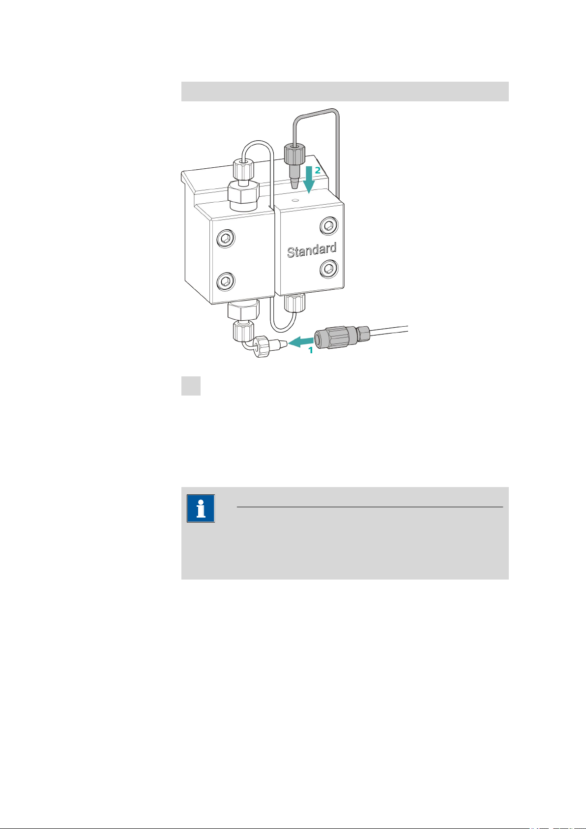
5.7 Servicing the inline filter
■■■■■■■■■■■■■■■■■■■■■■
Connecting the input for the high-pressure pump
■ Remove the stopper from the coupling. Tighten the coupling to
1
the pressure screw located on the pump head input capillary (1).
■ Reconnect the pump head output capillary to the pump head out-
put (2).
5.7 Servicing the inline filter
NOTE
You can find a video sequence for this task in the Multimedia Guide IC
Maintenance or on the Internet at http://www.metrohm.com/com/
Support/Video/ICGeneral.html?q=14.
Maintenance interval
Accessories For this task you need the following accessories:
The filter has to be replaced at least every 3 months; the filter has to be
replaced more frequently if you are working with high backpressure.
■ Adjustable wrench (6.2621.000) from the accessory kit: Vario/Flex
Basic (6.5000.000)
■ Tweezers
■ A new filter from the packaging (6.2821.130)
■■■■■■■■
66
930 Compact IC Flex ChS (2.930.1200)
Page 75

■■■■■■■■■■■■■■■■■■■■■■
5 Operation and maintenance
Removing the filter
Figure 20 Inline filter – removing the filter
Filter housing
1
Inline filter housing. Part of the accessories
(6.2821.120).
Filter (6.2821.130)
3
Packaging contains 10 pieces.
1
Shutting off the flow
Switch off the high-pressure pump in the software.
2
Removing the inline filter
Unscrew the both pressure screws from the inline filter.
3
Unscrewing the filter screw
Use two adjustable wrenches (6.2621.000) to loosen the filter screw
(20-2) from the filter housing (20-1) and unscrew it by hand.
4
Removing the filter
Remove the old filter (20-3) using tweezers.
Filter screw
2
Screw for the inline filter. Part of the accessories (6.2821.120).
930 Compact IC Flex ChS (2.930.1200)
■■■■■■■■
67
Page 76

5.7 Servicing the inline filter
■■■■■■■■■■■■■■■■■■■■■■
Inserting a new filter
1
Inserting a new filter
■ Place the new filter flat in the filter housing (20-1) using tweezers.
2
Mounting the filter screw
■ Screw the filter screw (20-2) back into the filter housing (20-1)
and tighten by hand. Then use two adjustable wrenches
(6.2621.000) to tighten it slightly.
3
Remounting the inline filter
■ Screw pressure screws back onto the inline filter.
4
Rinsing the inline filter
■ Dismantle the guard column (if present) and the separation col-
umn and replace with a coupling (6.2744.040).
■ Rinse the instrument with eluent.
■ Reinsert the columns after 10 minutes.
■■■■■■■■
68
930 Compact IC Flex ChS (2.930.1200)
Page 77

■■■■■■■■■■■■■■■■■■■■■■
5.8 Servicing the pulsation absorber
CAUTION
The pulsation absorber is maintenance-free and must not be opened.
5.9 Injection valve
Maintenance on the injection valve is best performed by specialist personnel from Metrohm during annual service.
5.10 Suppressor
5.10.1 Notes for operating the suppressor
5 Operation and maintenance
NOTE
The suppressor units must never be regenerated in the same flow direction the eluent is pumped. Therefore, always mount the input and output capillaries according to the diagram outlined in Chapter Connecting
the suppressor, page 30.
The suppressor consists of three suppressor units, which are used in rotation for suppression, regenerated with regeneration solution, and rinsed
with ultrapure water. In order to record every new chromatogram under
comparable conditions, you should normally work with a freshly regenerated suppressor.
CAUTION
The suppressor must never be switched over if liquid is not flowing
through it, since otherwise it may become jammed. If the suppressor is
in a dry state, it must be rinsed for at least five minutes before it may be
switched over.
930 Compact IC Flex ChS (2.930.1200)
■■■■■■■■
69
Page 78

5.10 Suppressor
1
2
3
4
5
CAUTION
The suppressor has to be regenerated (see Chapter 5.10.3.2, page
71), cleaned (see Chapter 5.10.3.3, page 72) or replaced (see Chapter 5.10.3.4, page 74) if the capacity of the suppressor is reduced or
if the backpressure is high.
5.10.2 Taking care of the suppressor housing
CAUTION
The transparent suppressor housing can become fogged.
The suppressor housing is made of PMMA (poly(methyl methacrylate)).
It can become scratched and foggy if cleaned improperly. This can
make viewing the rotor difficult or impossible.
■ Do not use any scouring agents for cleaning.
■ Do not use any solvents for cleaning.
■■■■■■■■■■■■■■■■■■■■■■
5.10.3 Servicing the suppressor
5.10.3.1
Figure 21 Parts of the suppressor
1
3
5
Parts of the suppressor
Union nut
Rotor
Slot in the housing
Connecting piece (6.2832.010)
2
Housing
4
■■■■■■■■
70
930 Compact IC Flex ChS (2.930.1200)
Page 79

■■■■■■■■■■■■■■■■■■■■■■
5.10.3.2 Regenerating the suppression rotor
If the suppressor units are loaded with certain heavy metals (such as iron)
or organic contamination for long periods, then the standard regeneration
solution may no longer be able to completely remove them. This constantly reduces the capacity of the suppressor units, which results in
reduced phosphate sensitivity in mild cases and a large increase in the
baseline in severe cases.
If such capacity problems occur at one or more positions, all suppressor
units must be regenerated with one of the following solutions:
■ Contamination with heavy metals:
1 mol/L H2SO4 + 0.1 mol/L oxalic acid
■ Contamination with organic cationic complexing agents:
0.1 mol/L H2SO4 / 0.1 mol/L oxalic acid / acetone 5%
■ Heavy contamination with organic substances:
0.2 mol/L H2SO4 / acetone ≥ 20%
CAUTION
5 Operation and maintenance
Pump tubing made of PVC must not be used for solutions containing
organic solvents.
We recommend using the high-pressure pump for regeneration.
Regenerating the suppressor
1
Disconnecting the suppressor from the IC system
■ Disconnect the capillaries of the suppressor labeled regenerant
and rinsing solution from the IC system.
2
Regenerating the suppressor
Regenerate the three suppressor units one after the other for approx.
15 minutes using one of the solutions mentioned above.
■ Connect the capillary labeled regenerant to the outlet of the
high-pressure pump using a coupling (6.2744.040).
■ Set the flow of the high-pressure pump to 0.5 mL/min in the soft-
ware.
■ Switch on the high-pressure pump.
If the pressure decreases during regeneration, slowly increase the
flow of the pump to a maximum of 2 mL/min. When doing so,
make sure that the pressure does not exceed 2 MPa!
■ After approx. 15 minutes, switch off the high-pressure pump.
930 Compact IC Flex ChS (2.930.1200)
■■■■■■■■
71
Page 80

5.10 Suppressor
■■■■■■■■■■■■■■■■■■■■■■
■ In the software, use the Step command to switch to the next
suppressor unit and regenerate it as described above.
■ As soon as all three suppressor units have been regenerated, dis-
connect the capillary labeled regenerant from the coupling.
3
Rinsing the suppressor
After regeneration, each of the three suppressor units must be rinsed
with degassed ultrapure water for about 15 minutes.
■ Connect the capillary labeled rinsing solution to the outlet of
the high-pressure pump using a coupling (6.2744.040).
■ Set the flow of the high-pressure pump to 0.5 mL/min in the soft-
ware.
■ Switch on the high-pressure pump.
If the pressure decreases during rinsing, slowly increase the flow
of the pump to a maximum of 2 mL/min. When doing so, make
sure that the pressure does not exceed 2 MPa!
■ After approx. 15 minutes, switch off the high-pressure pump.
■ In the software, use the Step command to switch to the next
suppressor unit and rinse it as described above.
■ As soon as all three suppressor units have been rinsed, disconnect
the capillary labeled rinsing solution from the coupling.
4
Connecting the suppressor to the IC system
■ Reconnect the capillaries of the suppressor labeled regenerant
and rinsing solution to the IC system.
■ Reconnect the outlet of the high-pressure pump to the IC system.
5.10.3.3 Cleaning the suppressor
In the following cases, it may be necessary to clean the suppressor:
■ Increased backpressure at the suppressor's connection tubing.
■ Blockage of the suppressor which cannot be eliminated (solutions can
no longer be pumped through the suppressor).
■ Jamming of the suppressor which cannot be eliminated (suppressor
can no longer be switched over).
Cleaning the suppressor
1
Disconnecting the suppressor from the IC system
■ Switch off the instrument.
■ Disconnect all capillaries of the suppressor from the IC system.
■■■■■■■■
72
930 Compact IC Flex ChS (2.930.1200)
Page 81

■■■■■■■■■■■■■■■■■■■■■■
5 Operation and maintenance
2
Dismantling the suppressor
■ Unscrew union nut (21-1) from the housing (21-4).
■ Pull the connecting piece (21-2) out of the housing together with
the the rotor (21-3).
If rotor A gets stuck in the housing, you can knock it loose as follows:
Put a pointed object into the slot in the housing and use it to
knock rotor A loose.
■ Detach the connecting piece from the rotor.
3
Rinsing the capillaries
■ Connect each of the 6 PTFE capillaries fastened to the connecting
piece (21-2) to the high-pressure pump in order and pump ultrapure water through them.
■ Check whether water comes out at the connecting piece.
If one of the capillaries remains blocked, the connecting piece (see
"Replacing parts of the suppressor", page 75) has to be replaced
(order number 6.2835.010).
4
Cleaning the rotor
■ Clean the surface of the rotor (21-3) with ethanol using a lint-free
cloth.
5
Inserting the rotor
CAUTION
Rotor A may be destroyed during start-up if not inserted correctly.
930 Compact IC Flex ChS (2.930.1200)
■■■■■■■■
73
Page 82

5.10 Suppressor
■■■■■■■■■■■■■■■■■■■■■■
■ Insert the rotor (21-3) into the housing (21-4) in such a way that
the tubing connections on the rear of rotor fit into the corresponding recesses inside the housing and one of the three holes
of the rotor is visible from below in the slot of the housing (21-5).
■ The rotor's sealing surface is approximately 4 mm inside the hous-
ing if the rotor is inserted correctly. If this is not the case, the
rotor must be moved into the right position from below using a
sharp object.
6
Cleaning the connecting piece
■ Clean the sealing surface of the connecting piece (21-2) with
ethanol using a lint-free cloth.
7
Inserting the connecting piece
■ Insert the connecting piece (21-2) into the housing in such a way
that the connector 1 is on top and the three pins of the connecting piece fit into the corresponding recesses on the housing.
■ Reattach the union nut (21-1) onto the housing and tighten by
hand (do not use a tool).
8
Connecting and conditioning the suppressor
■ Reconnect the suppressor to the IC system.
■ Before switching the suppressor over for the first time, rinse each
of the three suppressor units with solution for 5 minutes.
5.10.3.4 Replacing parts of the suppressor
In the following cases, it might be necessary to replace parts of the suppressor:
■ Loss of suppressor capacity which cannot be eliminated (reduced phos-
phate sensitivity and/or significant rise in the baseline).
■ Blockage of the suppressor which cannot be eliminated (solutions can
no longer be pumped through the suppressor).
Both the rotor and the connecting piece can be replaced.
■■■■■■■■
74
930 Compact IC Flex ChS (2.930.1200)
Page 83

■■■■■■■■■■■■■■■■■■■■■■
5 Operation and maintenance
Replacing parts of the suppressor
1
Disconnecting the suppressor from the IC system
■ Switch off the instrument.
■ Disconnect all capillaries of the suppressor from the IC system.
2
Dismantling the suppressor
■ Unscrew union nut (21-1) from the housing (21-4).
■ Pull the connecting piece (21-2) out of the housing together with
the the rotor (21-3).
If rotor A gets stuck in the housing, you can knock it loose as follows:
Put a pointed object into the slot in the housing and use it to
knock rotor A loose.
■ Detach the connecting piece from the rotor.
3
Cleaning the new rotor
■ Clean the surface of the new rotor (21-3) with ethanol using a
lint-free cloth.
4
Inserting the new rotor
CAUTION
Rotor A may be destroyed during start-up if not inserted correctly.
Insert the new rotor (21-3) into the housing (21-4) in such a way
■
that the tubing connections on the rear of rotor fit into the corresponding recesses inside the housing and one of the three holes
of the rotor is visible from below in the slot of the housing (21-5).
930 Compact IC Flex ChS (2.930.1200)
■■■■■■■■
75
Page 84

5.10 Suppressor
■■■■■■■■■■■■■■■■■■■■■■
■ The rotor's sealing surface is approximately 4 mm inside the hous-
ing if the rotor is inserted correctly. If this is not the case, the
rotor must be moved into the right position from below using a
sharp object.
5
Cleaning the new connecting piece
■ Clean the surface of the new connecting piece (21-2) with etha-
nol using a lint-free cloth.
6
Inserting the new connecting piece
■ Insert the connecting piece (21-2) into the housing (21-4) in such
a way that the connector 1 is on top and the three pins of the
connecting piece fit into the corresponding recesses on the housing.
■ Reattach the union nut (21-1) and tighten it by hand.
7
Connecting and conditioning the suppressor
■ Reconnect all capillaries of the suppressor to the IC system.
■ Before switching the suppressor over for the first time, rinse the
three suppressor units with solution for 5 minutes.
■■■■■■■■
76
930 Compact IC Flex ChS (2.930.1200)
Page 85

■■■■■■■■■■■■■■■■■■■■■■
5.11 Servicing the detector
Follow the maintenance instructions in the the detector's manual.
5.12 Rinsing the sample path
Before a new sample is measured, the sample path has to be rinsed with it
long enough to prevent the measuring result from being falsified by the
previous sample (sample carry-over).
The time required to rinse the sample path with the new sample is called
the rinsing time. The rinsing time depends on the transfer time.
The transfer time corresponds to the time the sample needs to flow from
the sample vessel to the end of the sample loop. The transfer time
depends on the following factors:
■ The pump capacity of the peristaltic pump or Dosino
■ The total capillary volume
■ The volume of the gas removed from the sample by the sample degas-
ser
5 Operation and maintenance
The transfer time can be determined as follows:
Determining the transfer time
1
Emptying the sample path
Pump air through the sample path (pump tubing, tubing connections, capillary in the degasser, sample loop) for several minutes until
all liquid is displaced by the air.
2
Aspirating the sample and measuring the time
Aspirate a sample typical for the later application and use a stopwatch to measure the time the sample needs to go from the sample
vessel to the end of the sample loop.
The time upon stopping the watch corresponds to the "transfer
time".
If the sample is injected automatically, the rinsing time has to be at least
three times the transfer time.
930 Compact IC Flex ChS (2.930.1200)
■■■■■■■■
77
Page 86

5.13 Separation column
■■■■■■■■■■■■■■■■■■■■■■
Checking the rinsing time
You can determine if the applied rinsing time is sufficient by measuring
the sample carry-over directly. Proceed as follows to do this:
1
Preparing two samples
■ Sample A: A typical sample for the application.
■ Sample B: Ultrapure water.
2
Determining "Sample A"
Allow "Sample A" to run through the sample path for the duration of
the rinsing time; inject and then measure it.
3
Determining "Sample B"
Allow "Sample B" to run through the sample path for the duration of
the rinsing time; inject and then measure it.
4
Calculating the sample carry-over
The sample carry-over corresponds to the ratio of the peak areas of
the measurement from Sample B to the measurement from Sample
A. The smaller this ratio is, the smaller the sample carry-over. This
ratio can be changed by varying the rinsing time. This can be used to
determine the required rinsing time for the application.
5.13 Separation column
5.13.1 Separating efficiency
The analysis quality that can be attained depends in a large part on the
separating efficiency of the separation column being used. The separation
efficiency of the selected separation column must be sufficient for the current analysis problems. If difficulties arise, start by checking the quality of
the separation column in each case by recording a standard chromatograph.
You can find detailed information on the separation columns available
from Metrohm in the leaflet provided along with your separation column,
in the Metrohm IC Column Program (available from your Metrohm
representative) or on the Internet at http://www.metrohm.com in the Ion
Chromatography product area. You can find information on special IC
applications in the corresponding "Application Bulletins" or "Applica-
tion Notes", which are available on the Internet at http://
www.metrohm.com in the Applications area or free of charge upon
request from your responsible Metrohm representative.
■■■■■■■■
78
930 Compact IC Flex ChS (2.930.1200)
Page 87

■■■■■■■■■■■■■■■■■■■■■■
5.13.2 Protecting the separation column
We recommend using the following protective measures so that the separation column retains its separating efficiency for as long as possible:
■ Microfilter both the sample and the eluent (0.45 µm filter) and aspirate
the eluent via the aspiration filter (6.2821.090) as well.
■ Always use a guard column. Information regarding which guard col-
umn is suitable for your separation column can be found in the
Metrohm IC Column Program (which is available from your
Metrohm representative), the leaflet provided along with your separation column, the product information about the separation column at
http://www.metrohm.com (Ion Chromatography product area), or
obtained directly from your representative.
■ Always use the pulsation absorber.
5.13.3 Storing the separation column
Always store separation columns you do not need in a sealed and filled
state according to the column manufacturer's specifications.
5 Operation and maintenance
5.13.4 Regenerating the separation column
The separation column can be regenerated according to the column manufacturer's specifications if the separation characteristics of the column
have deteriorated. You can find information on regenerating separation
columns available from Metrohm on the leaflet provided with every column.
NOTE
Regeneration is intended as a last resort. It should not be carried out
regularly.
930 Compact IC Flex ChS (2.930.1200)
■■■■■■■■
79
Page 88

5.14 Quality Management and qualification with Metrohm
■■■■■■■■■■■■■■■■■■■■■■
5.14 Quality Management and qualification with
Metrohm
Quality management
Metrohm offers you comprehensive support in implementing quality management measures for instruments and software. Further information on
this can be found in the brochure "Metrohm Quality Management"
available from your local Metrohm representative.
Qualification
Please contact your local Metrohm representative for support in qualification of instruments and software. The Installation Qualification (IQ)
and Operational Qualification (OQ) are offered by Metrohm representatives as a service. They are carried out by trained employees using standardized qualification documents and in accordance with the currently
applicable requirements of the regulated industry. Further information on
this can be found in the brochure "Analytical Instrument Qualifica-
tion – Confidence in quality with IQ/OQ".
Maintenance
The electronic and mechanical functional groups of Metrohm instruments
can and should be checked by specialist personnel from Metrohm as part
of a regular preventive maintenance schedule. Please ask your local
Metrohm representative regarding the precise terms and conditions
involved in concluding a corresponding maintenance agreement. Further
information on this can be found in the brochure "Metrohm Care Con-
tracts – Protect your investment the smart way" available from your
local Metrohm representative.
■■■■■■■■
80
930 Compact IC Flex ChS (2.930.1200)
Page 89

■■■■■■■■■■■■■■■■■■■■■■
6 Troubleshooting
Problem Cause Remedy
6 Troubleshooting
Marked drop in
pressure.
The baseline has a
large amount of
noise.
The baseline is drifting.
Leak in the system. Check all capillary connections and seal leaks,
if necessary (see Chapter 3.2, page 12).
The eluent path has a leak. Check the eluent path and fix the leak.
High-pressure pump – Con-
Clean pump valves (see Chapter 5.6, page 53).
taminated pump valves.
The eluent path is blocked. Check the eluent path and fix the blockage.
High-pressure pump –
Defective piston seals.
The pulsation absorber is
not connected or is defec-
Replace the piston seals (see Chapter 5.6,
page 53).
Connect (see Chapter 3.8, page 24) or replace
the pulsation absorber.
tive.
Leak in the system. Check all capillary connections and seal leaks,
if necessary (see Chapter 3.2, page 12).
The organic solvent in the
eluent is evaporating.
■ Check the eluent bottle cap (see Chapter
3.5, page 18).
■ Constantly stir the eluent.
The pressure in the
system markedly
increases.
The inline filter
(6.2821.120) is blocked.
Suppressor blocked. ■ Regenerate the suppressor (see Chapter
Guard column – Blocked. Replace the guard column (see Chapter 3.15,
Separation column –
Blocked.
930 Compact IC Flex ChS (2.930.1200)
Replace the filter (6.2821.130) .
5.10.3.2, page 71).
Note: 6.2821.180 pump tubing connection
with filter must be used.
page 40).
■ Regenerate the separation column (see
Chapter 5.13.4, page 79).
■ Replace the separation column (see "Con-
necting the separation column", page 44).
Note: Samples should always be microfiltered .
■■■■■■■■
81
Page 90

6.1
Problem Cause Remedy
■■■■■■■■■■■■■■■■■■■■■■
The retention times
in the chromatogram have changed
unexpectedly.
Peak areas are
lower than
expected.
Injection valve – Valve
blocked.
Separation column –
Diminished separating efficiency.
The eluent contains gas
bubbles.
High-pressure pump –
Defective.
Sample – There is a leak in
the sample path.
Sample – The sample path
is blocked.
Sample – The sample loop
is not (completely) filled.
Have the valve cleaned (by a Metrohm service
technician).
■ Regenerate the separation column (see
Chapter 5.13.4, page 79).
■ Replace the separation column (see "Con-
necting the separation column", page 44).
■ Ensure that the connectors for the eluent
degasser are firmly connected .
■ Deaerate the high-pressure pump (see Fig-
ure , page 39).
Request Metrohm Service.
Find and fix the leak in the sample path.
Find and fix the blockage in the sample path.
Adjust the transfer time for the sample (see
"Determining the transfer time", page 77).
Data of the separation column cannot
be read.
Individual peaks are
greater than
expected.
Suppressor – Insufficient flow of regeneration solution or
rinsing solution.
The background
conductivity is too
high.
Sample – There are gas
Use the sample degasser .
bubbles in the sample.
Column chip contaminated.
Clean the contact surfaces of the column chip
with alcohol.
Column chip is defective. 1. Save column configuration in MagIC Net™.
2. Notify Metrohm Service.
Sample – Sample carryover from the previous
Check the rinsing time (see "Checking the rinsing time", page 78).
measurement.
There is a leak in the sys-
Check all connections.
tem.
Suppressor – Backpressure
too high.
Clean the suppressor (see Chapter 5.10.3.3,
page 72) or replace parts (see Chapter
5.10.3.4, page 74).
The suppressor is not connected.
Connect the suppressor (see Chapter 3.10,
page 27).
■■■■■■■■
82
930 Compact IC Flex ChS (2.930.1200)
Page 91

■■■■■■■■■■■■■■■■■■■■■■
Problem Cause Remedy
6 Troubleshooting
The retention times
are poorly reproducible.
Baseline increasing
strongly.
The incorrect eluent is
being used.
Suppressor – No or insufficient flow of regeneration
Change the eluent (see Chapter 5.4.2, page
51).
Check the flow of the regeneration solution
and the rinsing solution .
solution or rinsing solution.
The eluent path has a leak. Check all of the connections along the eluent
path and fix the leak.
The eluent path is blocked. Check the eluent path and fix the blockage.
The eluent contains gas
bubbles.
■ Inspect the connectors for the eluent
degasser .
■ Deaerate the high-pressure pump (see
Chapter 3.14, page 38).
Suppressor – Reduced
capacity.
Regenerate the suppressor (see Chapter
5.10.3.2, page 71).
SPM – Reduced capacity. Regenerate the SPM (see Chapter 5.10.3.2,
page 71).
Chromatograms
have poor resolution
Extreme spread of
the peaks in the
chromatogram.
Splitting (dual
peaks)
Precision problems the measured values
are highly scattered.
Separation column –
Diminished separating efficiency.
Capillary connections –
dead volume in the system.
Guard column – Diminished efficiency.
Separation column – Dead
volume at the column
head.
Injection valve – Sample
loop.
■ Regenerate the separation column (see
Chapter 5.13.4, page 79).
■ Replace the separation column (see "Con-
necting the separation column", page 44).
Check the capillary connections (see Chapter
3.2, page 12) (use PEEK capillaries with an
inner diameter of 0.25 mm between the injection valve and detector).
■ Replace the guard column (see Chapter
3.15, page 40).
■ Install the separation column in the oppo-
site flow direction (if permitted by the leaflet) and rinse into a beaker.
■ Replace the separation column (see "Con-
necting the separation column", page 44).
Inspect the installation of the sample loop (see
"Optional: Exchanging the sample loop",
page 25).
930 Compact IC Flex ChS (2.930.1200)
■■■■■■■■
83
Page 92

6.1
Problem Cause Remedy
■■■■■■■■■■■■■■■■■■■■■■
Sample – There are gas
bubbles in the sample.
Sample – The rinsing volume is too small.
Injection valve – Defective. Request Metrohm Service.
Use the sample degasser .
Increase the rinsing time (see Chapter 5.12,
page 77).
■■■■■■■■
84
930 Compact IC Flex ChS (2.930.1200)
Page 93

■■■■■■■■■■■■■■■■■■■■■■
7 Technical specifications
7.1 Reference conditions
The technical specifications listed in this chapter refer to the following reference conditions:
7 Technical specifications
Ambient temperature
Instrument status Operating > 40 minutes (in equilibrium)
+25 °C (± 3 °C)
7.2 Instrument
IC system
Material Painted, CFC-free polyurethane hard foam, fire class V0
Operating pressure range
Intelligent components
■ Metal-free IC system
■ Compact system with modular design
■ 0 - 50 MPa (500 bar) high-pressure pump
■ 0 - 35 MPa (350 bar) standard PEEK system
iPump, iDetector, iColumn, intelligent Dosino, MagIC Net™
7.3 Ambient conditions
Operation
Ambient temperature
Humidity 20 - 80% relative humidity
+5 - +45 °C
Storage
Ambient temperature
Transport
Ambient temperature
930 Compact IC Flex ChS (2.930.1200)
–20 - +70 °C
–40 - +70 °C
■■■■■■■■
85
Page 94

7.4 Housing
7.4 Housing
Dimensions
Width 302 mm
Height 562 mm
Depth 368 mm
■■■■■■■■■■■■■■■■■■■■■■
Material of base
tray, housing and
Polyurethane hard foam (PUR) with flame retardation for fire class
UL94V0, CFC-free, coated
bottle holder
Operating elements
Indicators LED standby indicator
On/off switch On the rear of the instrument
7.5 Leak sensor
Type
Electronic, no calibration necessary
7.6 High-pressure pump
Type
■ Serial dual-piston pump
■ Intelligent pump head recognition
■ Chemically inert
■ Metal-free pump heads
■ Materials in contact with the eluent: PEEK, ZrO
■ Self-optimizing flow and pressure
, PTFE/PE
2
Flow rate
Adjustable flow
0.001 - 20.0 mL/min
range
Flow increment 1 µL/min
Reproducibility
< 0.1% deviation
of the eluent
flow
Pressure range
Pump 0 - 50.0 MPa (0 - 500 bar)
Pump head 0 - 35.0 MPa (0 - 350 bar) (applies for the standard PEEK pump head)
Residual pulsa-
< 1%
tion
■■■■■■■■
86
930 Compact IC Flex ChS (2.930.1200)
Page 95

■■■■■■■■■■■■■■■■■■■■■■
Safety shutdown
Function Automatic shutdown upon reaching the pressure limit values
Maximum pressure limit
■ Adjustable from 0.1 - 50 MPa (1 - 500 bar)
■ The pump is automatically shut down at the first piston stroke
above the maximum limit value
Minimum pressure limit
■ Adjustable from 0 - 49 MPa (0 - 490 bar)
■ The shutdown mechanism is inactive at 0 MPa
■ The shutdown mechanism becomes active 2 minutes after system
start
■ The pump is automatically shut down after 3 piston strokes below
the minimum pressure limit
7.7 Injection valve
7 Technical specifications
Actuator switch-
typ. 100 ms
ing time
Maximum operat-
35 MPa (350 bar)
ing pressure
Material PEEK
7.8 Suppressor
Resistance to solvents
Switching time typ. 100 ms
No restriction
7.9 Detector
You can find the technical specifications for the detector in the detector's
manual.
930 Compact IC Flex ChS (2.930.1200)
■■■■■■■■
87
Page 96

7.10 Power connection
7.10 Power connection
Required voltage 100 - 240 V ± 10% (autosensing)
■■■■■■■■■■■■■■■■■■■■■■
Required fre-
50 - 60 Hz ± 3 Hz (autosensing)
quency
Power consumption
■ 65 W for typical analysis application
■ 25 W standby (conductivity detector to 40 °C)
Power supply unit ■ Up to 300 W maximum, electronically monitored
■ Internal fuse 3.15 A
7.11 Interfaces
USB
Input 1 USB upstream, type B (for connection to the PC)
Output 2 USB downstream, type A
MSB 2 MSB Mini DIN 8-pin (female) (for Dosino, stirrer, remote lines, etc.)
Detector 1 15-pin high density DSUB (female)
Column recognition
Leak sensor 1 jack plug
for an intelligent column
Further connections
Auxiliary 1 15-pin DSUB (female)
Service 1 15-pin DSUB (female)
7.12 Safety specifications
This instrument fulfills the following electrical safety requirements:
CE marking in accordance with the EU directives:
■ 2006/95/EC (Low Voltage Directive, LVD)
■ 2004/108/EC (EMC Directive, EMC)
Federal Inspectorate for Heavy Current Installations ESTI (Accreditation
Number SCESp 033)
■ Safety mark for certification type 2 in accordance with NEV (type
testing with market monitoring, EMC conformity)
■■■■■■■■
88
930 Compact IC Flex ChS (2.930.1200)
Page 97

■■■■■■■■■■■■■■■■■■■■■■
7 Technical specifications
ETL Listed Mark:
■ Control number 3144965
■ UL 61010-1
■ CSA-C22.2 No. 61010-1
Design and testing According to EN/IEC/UL 61010-1, CSA-C22.2 No. 61010-1, EN/IEC
61010-2-010, EN/IEC 61010-2-081, EN/IEC 60529, degree of protection IP20, protection class I.
Safety instructions This document contains safety instructions which have to be followed
by the user in order to ensure safe operation of the instrument.
7.13 Electromagnetic compatibility (EMC)
Emission
■ EN/IEC 61326-1
■ EN/IEC 61000-6-3
■ EN 55022 / CISPR 22
■ EN/IEC 61000-3-2
■ EN/IEC 61000-3-3
Immunity ■ EN/IEC 61326-1
■ EN/IEC 61000-6-2
■ EN/IEC 61000-4-2
■ EN/IEC 61000-4-3
■ EN/IEC 61000-4-4
■ EN/IEC 61000-4-5
■ EN/IEC 61000-4-6
■ EN/IEC 61000-4-8
■ EN/IEC 61000-4-11
■ EN/IEC 61000-4-14
■ EN/IEC 61000-4-28
930 Compact IC Flex ChS (2.930.1200)
■■■■■■■■
89
Page 98

8 Warranty (guarantee)
Metrohm guarantees that the deliveries and services it provides are free of
defects in materials, design or manufacturing.
The general warranty period is 36 months (exclusions below) from the
date of delivery, or 18 months in the event of continuous operation. The
warranty remains valid on the condition that the servicing is provided by a
service organization authorized by Metrohm at defined intervals and with
a defined scope.
The warranty period for anion suppressors of the type "MSM" is 120
months from the date of delivery or 60 months in the case of continuous
operation.
The warranty period for IC separation columns is 90 days after start-up.
For third-party components that are recognizable as such, the manufacturer's warranty regulations apply.
■■■■■■■■■■■■■■■■■■■■■■
For instruments sold under the Metrohm NIRSystems brand, a full 16month warranty is applicable. In the event of continuous operation, the
warranty period is reduced by half.
Consumables and materials with limited storage life and glass breakage in
the case of electrodes or other glass parts are excluded from the warranty.
Warranty claims cannot be asserted if the ordering party has failed to
meet its payment obligations according to schedule.
During the warranty period, Metrohm undertakes either to replace free of
charge or to credit the purchaser for any modules or components that can
be shown to be faulty. Any transport or customs fees that may apply are
the responsibility of the ordering party.
The precondition for this is that the ordering party has to specify the article number, the article designation, an adequate error description, the
delivery date and (if applicable) the serial number or chip data in the Support Tracker. Metrohm then decides whether a replacement or a credit
note is to be issued or whether the faulty part has to be returned using
the Return Material Authorization (RMA). If a replacement or credit note is
issued, the ordering party undertakes to store the faulty part for at least
24 months in accordance with the current storage directives (in compliance with ESD guidelines) and to hold it in readiness for onsite inspection
or for return shipment to Metrohm. Metrohm reserves the right to invoice
the ordering party for these articles, including retroactively, in the event of
noncompliance with these preconditions.
■■■■■■■■
90
930 Compact IC Flex ChS (2.930.1200)
Page 99

■■■■■■■■■■■■■■■■■■■■■■
8 Warranty (guarantee)
The same warranty periods that are specified for a corresponding new
part apply to parts that are replaced or repaired within the above-mentioned warranty periods. However, replacement or repair of a part does
not extend the warranty period of the entire system.
Deficiencies arising from circumstances that are not the responsibility of
Metrohm, such as improper storage or improper use, etc., are expressly
excluded from the warranty.
Metrohm also offers a 120-month spare parts availability guarantee and a
60-month PC software support warranty, calculated from the date on
which the product is withdrawn from the market. The content of this warranty is the ability of the customer to obtain functioning spare parts or
appropriate software support at market prices during the time of the warranty period. This does not apply for software products sold under the
Metrohm NIRSystems brand.
If Metrohm AG is unable to meet this obligation due to circumstances
beyond the control of Metrohm AG, then the ordering party shall be
offered alternative solutions at preferential conditions.
930 Compact IC Flex ChS (2.930.1200)
■■■■■■■■
91
Page 100

9 Accessories
Up-to-date information on the scope of delivery and optional accessories
for your instrument can be found on the Internet.
When you receive your new instrument, we recommend downloading
the accessories list from the Internet, printing it out and keeping it
together with the manual for reference purposes.
Instruments currently sold
If you do not know the article number of your instrument, proceed as follows:
Downloading the accessories list
■■■■■■■■■■■■■■■■■■■■■■
NOTE
Go to the Metrohm website http://www.metrohm.com/com.
1
2
Click on .
The Search webpage will be displayed.
Enter a search term relating to the instrument into the search field
3
and click on Find.
The search results will be displayed.
In the search results, select the Devices tab (if it is not already
4
selected) and then click on the Metrohm article number of the
required instrument (e.g. 2.852.0050).
The page with information pertaining to the searched article is displayed.
Select the Parts tab.
5
The complete list of accessories with the scope of delivery and the
optional accessories will be displayed.
6
Click on .
■■■■■■■■
92
930 Compact IC Flex ChS (2.930.1200)
 Loading...