

Page 1
761 Compact IC
METROHM Ltd.
CH-9101 Herisau
Switzerland
Phone ++41 71 353 85 85
Fax ++41 71 353 89 01
8.761.1063
Instructions for Use
Page 2
CH-9101 Herisau/Switzerland
Phone ++41 71 353 85 85
Fax ++41 71 353 89 01
Internet www.metrohm.ch
E-Mail info@metrohm.ch
761 Compact IC
Program «761 PC Software 1.1»
8.761.1063 Instructions for Use
07.07.2004 / chs
Page 3

Table of contents
Table of contents
1 Introduction............................................................................................................1
1.1 Instrument description .......................................................................................... 1
1.2 Parts and controls .................................................................................................. 3
1.3 Information on the Instructions for Use ...........................................................10
1.3.1 Organization ......................................................................................... 10
1.3.2 Notation and pictograms...................................................................... 11
1.4 Safety notes........................................................................................................... 12
1.4.1 Electrical safety..................................................................................... 12
1.4.2 General precautionary rules ................................................................. 12
2 Installation .......................................................................................................... 13
2.1 Overview ................................................................................................................13
2.1.1 Flow chart ............................................................................................. 13
2.1.2 Connections in the 761 Compact IC.................................................... 13
2.2 Setting up the instrument.................................................................................... 15
2.2.1 Packaging............................................................................................. 15
2.2.2 Check.................................................................................................... 15
2.2.3 Location ................................................................................................ 15
2.3 Attaching the accessories ..................................................................................15
2.3.1 Connection of detector block............................................................... 15
2.3.2 Connection of syringe and aspirating tubing ....................................... 16
2.3.3 Connection of the drain tube for the inner compartment..................... 16
2.3.4 Connection of the drain tube for bottle rack ........................................ 17
2.3.5 Connection of PEEK capillaries............................................................ 17
2.3.6 Filter unit PEEK ..................................................................................... 18
2.4 Mains connection .................................................................................................19
2.4.1 Setting the mains voltage..................................................................... 19
2.4.2 Fuses .................................................................................................... 20
2.4.3 Mains cable and mains connection ..................................................... 20
2.4.4 On/off switching of the instrument ....................................................... 20
2.5 Connection to the PC........................................................................................... 21
2.5.1 Connecting cable ................................................................................. 21
2.5.2 Software installation.............................................................................. 21
2.5.3 Basic settings ....................................................................................... 22
2.6 High-pressure pump ............................................................................................ 25
2.6.1 Removing the transport security screws .............................................. 25
2.6.2 Installing the pulsation dampener ........................................................ 25
2.6.3 Connecting the eluent bottle ................................................................ 27
2.6.4 Deaerating the pump and rinsing the pulsation dampener................. 29
761 Compact IC
2.7 Precolumns and separating columns ............................................................... 31
2.7.1 General information on precolumns..................................................... 31
2.7.2 Precolumns with cartridge head........................................................... 31
2.7.3 Precolumn glass cartridges with cartridge holder ............................... 33
2.7.4 IC anion precolumn SUPERSEP .......................................................... 34
2.7.5 General information on separating columns........................................ 35
2.7.6 Selection of the sample loop................................................................ 35
2.7.7 Installation of the separating column without suppressor ................... 36
2.7.8 Installation of the separating column with suppressor ........................ 37
I
Page 4

Table of contents
2.8 Suppressor module ............................................................................................. 38
2.8.1 General information on suppressor module........................................ 38
2.8.2 Preparation of the peristaltic pump...................................................... 38
2.8.3 Connection of supply bottles ............................................................... 41
2.8.4 Connection of the suppressor module ................................................ 43
2.9 Putting into operation.......................................................................................... 45
2.9.1 Putting into operation without suppressor ........................................... 45
2.9.2 Putting into operation with suppressor ................................................ 46
2.10 Connection of external devices ......................................................................... 49
2.10.1 Connection of the 750 Autosampler .................................................... 49
2.10.2 Connection of the 766 IC Sample Processor ...................................... 50
2.10.3 Connection of other devices ................................................................ 52
3 Operating tutorial ....................................................................................... 53
3.1 Requirements........................................................................................................ 53
3.2 Preparations.......................................................................................................... 54
3.3 Calibration ............................................................................................................. 55
3.4 Sample determination ......................................................................................... 63
4 Operation............................................................................................................... 67
4.1 Fundamentals of the operation.......................................................................... 67
4.1.1 Starting/closing the program ............................................................... 67
4.1.2 Glossary................................................................................................ 68
4.1.3 Overview of program windows............................................................. 69
4.1.4 Main window elements......................................................................... 70
4.1.5 Icons of the main window..................................................................... 70
4.1.6 Overview of file types............................................................................ 71
4.1.7 Context sensitive menus ...................................................................... 72
4.1.8 Keyboard and mouse functions........................................................... 72
4.1.9 Help ...................................................................................................... 73
4.2 Instrument and software settings...................................................................... 74
4.2.1 Fonts..................................................................................................... 74
4.2.2 Security system .................................................................................... 74
4.2.3 Global settings ..................................................................................... 75
4.2.4 COM port.............................................................................................. 77
4.3 Systems ................................................................................................................. 78
4.3.1 System window .................................................................................... 78
4.3.2 System file handling ............................................................................. 78
4.3.3 System functions .................................................................................. 79
Connect and disconnect system ................................................. 79
Start/stop hardware and record baseline .................................... 79
Start/stop determinations............................................................. 80
Options for determinations........................................................... 80
4.3.4 System settings .................................................................................... 82
Modify system window ................................................................. 82
Watch window display.................................................................. 82
Set start mode .............................................................................. 82
Print system parameters .............................................................. 83
4.3.5 PC icon ................................................................................................. 83
761 Compact IC
II
Page 5

Table of contents
Menu options for PC icon............................................................. 83
Select processing method and data source................................ 83
4.3.6 Watch window....................................................................................... 84
Menu options for screen icon....................................................... 84
4.3.7 Instrument icon ..................................................................................... 85
Menu options for instrument icon................................................. 85
System parameters for disconnected system ............................. 85
Instrument control for connected system .................................... 86
Time program ............................................................................... 88
Configuration ................................................................................90
Hardware settings ........................................................................ 91
4.3.8 Timer .....................................................................................................94
4.3.9 System state window............................................................................ 95
Status messages.......................................................................... 95
Error messages ............................................................................ 96
4.4 Methods .................................................................................................................97
4.4.1 Method file handling ............................................................................. 97
4.4.2 Passport................................................................................................ 97
General ......................................................................................... 98
Sample.......................................................................................... 99
Column ....................................................................................... 100
Eluent .......................................................................................... 101
Comment .................................................................................... 101
Method Log ................................................................................ 102
Data Log ..................................................................................... 103
4.4.3 Method setup...................................................................................... 104
General ....................................................................................... 104
Measure ...................................................................................... 104
Filters .......................................................................................... 105
Processing.................................................................................. 106
Math ............................................................................................ 107
4.4.4 Integration........................................................................................... 109
Setup........................................................................................... 110
Events ......................................................................................... 112
4.4.5 Calibration and quantification............................................................. 117
General information .................................................................... 117
Notations..................................................................................... 118
External standard calibration...................................................... 119
Component table........................................................................ 119
Peak identification ...................................................................... 121
Concentration table .................................................................... 123
Calibration curve......................................................................... 125
Update calibration ...................................................................... 127
Load and save calibration data.................................................. 128
Import and export calibration data ............................................. 128
Put out calibration curves ........................................................... 128
4.4.6 Report output...................................................................................... 129
Report options ............................................................................129
4.5 Chromatograms..................................................................................................141
4.5.1 Chromatogram window ...................................................................... 141
4.5.2 Chromatogram file handling............................................................... 142
Open chromatogram.................................................................. 142
Save chromatogram................................................................... 143
Close chromatogram.................................................................. 143
Delete chromatogram................................................................. 143
Export chromatogram................................................................. 143
Import chromatogram ................................................................ 144
4.5.3 Graphical representation.................................................................... 145
761 Compact IC
III
Page 6

Table of contents
Appearance................................................................................ 145
Other graphical functions........................................................... 149
4.5.4 Peak editor.......................................................................................... 150
Switching on/off the peak editor ................................................ 150
Peak editor functions.................................................................. 150
Moving the cursor....................................................................... 151
4.5.5 Printing................................................................................................ 152
Page layout for printing .............................................................. 152
Printer settings............................................................................ 153
Print preview ............................................................................... 153
Printing........................................................................................ 153
4.5.6 Miscellaneous functions..................................................................... 153
Reintegration .............................................................................. 153
Recalibration............................................................................... 153
Subtraction of a chromatogram................................................. 154
Data compression ...................................................................... 154
Invert chromatogram.................................................................. 154
Autodatabase options................................................................ 155
Indicate active Autodatabase program ..................................... 155
4.6 Sample queue ..................................................................................................... 156
4.6.1 Sample queue file handling................................................................ 156
Open sample queue................................................................... 156
Save sample queue.................................................................... 156
Delete sample queue ................................................................. 156
4.6.2 Sample queue control ........................................................................ 157
Sample queue overview table .................................................... 157
Start sample queue .................................................................... 158
Pause sample queue ................................................................. 159
Cancel last run............................................................................ 159
Reset sample queue .................................................................. 159
4.6.3 Sample queue editor.......................................................................... 159
Open queue editor window........................................................ 159
Sample queue editor functions .................................................. 161
Print sample queue .................................................................... 161
Close sample queue editor ........................................................ 161
4.7 Batch reprocessing............................................................................................ 162
4.7.1 Batch reprocessing queue file handling ............................................ 162
Open batch reprocessing queue ............................................... 162
Create new batch reprocessing queue...................................... 162
Save batch reprocessing queue ................................................ 162
4.7.2 Perform batch reprocessing............................................................... 163
Reprocess options window........................................................ 163
Merge chromatograms .............................................................. 166
4.7.3 Batch reprocessing queue editor....................................................... 167
Open batch reprocessing queue editor window ....................... 167
Batch reprocessing queue editor functions............................... 168
Print batch reprocessing queue................................................. 168
Close batch reprocessing queue editor .................................... 168
761 Compact IC
IV
Page 7

Table of contents
5 Notes – Maintenance – Faults....................................................169
5.1 Practical notes on ion chromatography .........................................................169
5.1.1 Separating columns............................................................................ 169
5.1.2 High-pressure pump .......................................................................... 170
5.1.3 Eluents ................................................................................................ 171
5.1.4 Peristaltic pump.................................................................................. 171
5.1.5 Suppressor module ............................................................................ 172
5.1.6 Connections........................................................................................ 172
5.2 Maintenance and servicing...............................................................................173
5.2.1 General information ............................................................................ 173
5.2.2 Passivation.......................................................................................... 173
5.2.3 Recycling ............................................................................................ 174
5.2.4 Shutdown............................................................................................ 174
5.2.5 Changing separating columns........................................................... 174
5.2.6 Maintenance work at the pump head ................................................176
5.2.7 Regeneration of the suppressor module ...........................................180
5.2.8 Cleaning the suppressor .................................................................... 181
5.2.9 Replacing the suppressor .................................................................. 183
5.2.10 Exchanging the pump tubing ............................................................. 185
5.3 Faults and malfunctions....................................................................................186
5.3.1 Error messages ..................................................................................186
5.3.2 Malfunctions and their rectification..................................................... 186
5.4 Diagnostic tests / Validation / GLP..................................................................188
6 Appendix.............................................................................................................. 189
6.1 Technical data.....................................................................................................189
6.1.1 Conductivity measurement................................................................. 189
6.1.2 Conductivity detector.......................................................................... 189
6.1.3 Injection valve .....................................................................................190
6.1.4 High-pressure pump .......................................................................... 190
6.1.5 Peristaltic pump.................................................................................. 191
6.1.6 Suppressor module ............................................................................ 191
6.1.7 Leak detector...................................................................................... 191
6.1.8 RS232 interface .................................................................................. 191
6.1.9 Remote interface................................................................................. 192
6.1.10 Analog output .....................................................................................192
6.1.11 Mains connection ............................................................................... 192
6.1.12 Safety specifications........................................................................... 192
6.1.13 Electromagnetic compatibility (EMC)................................................. 193
6.1.14 Ambient temperature.......................................................................... 193
6.1.15 Housing............................................................................................... 193
6.2 Standard equipment...........................................................................................194
6.3 Optional accessories .........................................................................................198
6.3.1 Accessories for capillary connections................................................ 198
6.3.2 High-pressure pump .......................................................................... 199
6.3.3 Separating columns and precolumns................................................ 200
6.3.4 Additional devices and cables ........................................................... 205
761 Compact IC
6.4 Warranty and conformity...................................................................................206
6.4.1 Warranty.............................................................................................. 206
6.4.2 EU Declaration of conformity.............................................................. 207
6.4.3 Certificate of conformity and system validation ................................. 208
6.5 Index .....................................................................................................................209
V
Page 8

Table of contents
List of figures
Fig. 1: Front of the 761 Compact IC .......................................................................... 3
Fig. 2
: Rear of the 761 Compact IC........................................................................... 4
Fig. 3
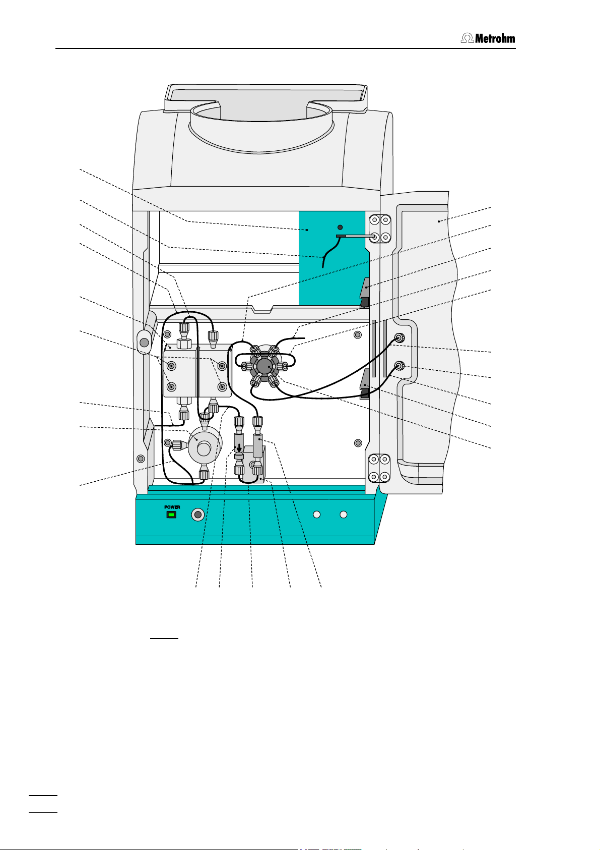
: Interior of the 2.761.0010 Compact IC ...........................................................6
Fig. 4
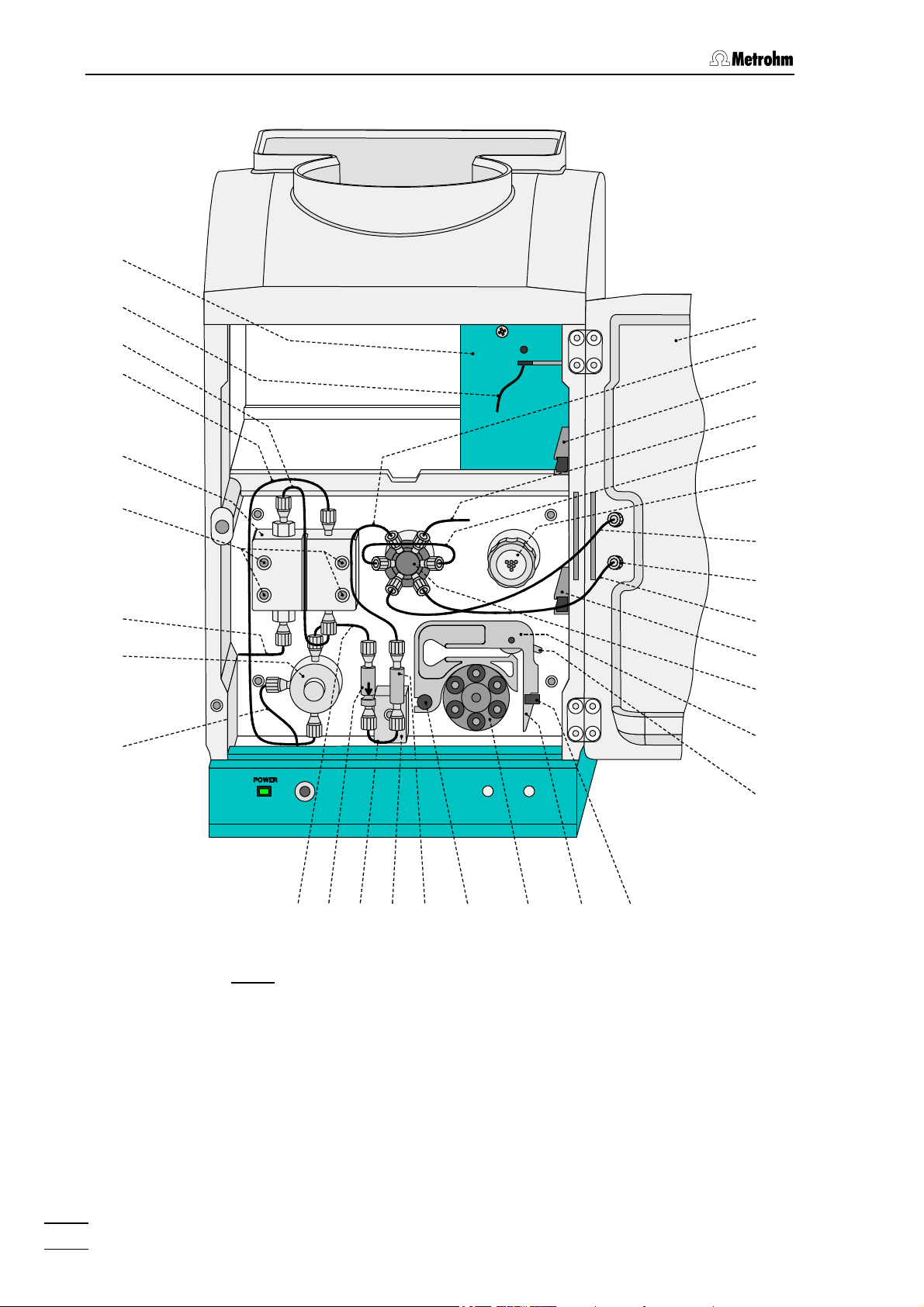
: Interior of the 2.761.0020 Compact IC ...........................................................8
Fig. 5
: Connecting diagram for 2.761.0010 Compact IC without suppressor........ 14
Fig. 6
: Connecting diagram for 2.761.0020 Compact IC with suppressor............. 14
Fig. 7
: Connectors for capillaries............................................................................. 17
Fig. 8
: 6.2821.000 Filter unit PEEK ..........................................................................18
: Setting the mains voltage .............................................................................20
Fig. 9
Fig. 10
: Connection of the pulsation dampener........................................................ 26
Fig. 11
: Connection of eluent bottle........................................................................... 28
Fig. 12
: Installation of precolumn cartridges with cartridge head............................. 32
Fig. 13
: Installation of precolumn glass cartridges with cartridge holder ................. 34
Fig. 14
: Installation of column without suppressor.................................................... 37
Fig. 15
: Installing pump tubings ................................................................................39
Fig. 16
: Connection of the separating column with suppressor ...............................40
Fig. 17
: Connection of supply bottles........................................................................ 42
: Connections at suppressor module ............................................................. 43
Fig. 18
Fig. 19
: Components of the pump head .................................................................177
: Replacement of the piston seal 112 ..........................................................177
Fig. 20
Fig. 21
: Components of inlet valve 113 and outlet valve 114................................. 179
Fig. 22
: Assembling the suppressor........................................................................ 183
761 Compact IC
VI
Page 9

Table of contents
List of numbered parts and controls
1 Door to interior .................................3,7,9
2 Connection for syringe...........................3
3 Feedthrough for aspirating tubing ......... 3
4 Aspirating tubing..............................3,7,9
5 Feedthrough for capillaries .................... 3
6 Connection for drain tube .....................3
7 Feedthrough for capillaries .................... 3
8 Connection to purge valve ....................3
9 Mains pilot lamp.....................................3
10 Bottle rack ...........................................3,5
11 Opening for detector cable....................5
12 Opening for inlet capillaries ...................5
13 Opening for outlet capillaries.................5
14 Connection for drain tube ......................5
15 Knurled screw ........................................5
16 Rear panel opening ...............................5
17 Detachable rear panel ...........................5
18 Transport security screws ...................... 5
19 Mains switch .....................................5,20
20 Mains connection plug .....................5,20
21 Fuse holder ....................................... 5,20
22 RS232 interface...................................... 5
23 Connection for detector block ...............5
24 Remote interface.................................... 5
25 Serial number.........................................5
26 Inlet capillary for injector ................7,9,26
27 Mounting rail .............................7,9,37,40
28 Column connection
capillary ...........................7,9,32,34,37,40
29 Sample loop........................................7,9
30 Connection capillary to syringe ..........7,9
31 Rotary nipple for aspirating tube ........7,9
32 Injection valve.......................7,9,26,37,40
33 PEEK coupling ............................... 7,9,40
34 Leak detector ......................................7,9
35 Connection capillary .....................7,9,26
36 Filter unit PEEK ....................7,9,18,26,40
37 Connection capillary ......................7,9,26
38 Connection capillary ...........................7,9
39 Purge valve.....................................7,9,26
40 Aspirating capillary..............................7,9
41 Fastening screws ................................7,9
42 Pump head...................................7,9,177
43 Connection capillary............................7,9
44 Connection capillary............................7,9
45 Inlet capillary for
detector block .......................... 7,9,37,40
46 Detector block .......................... 7,9,37,40
47 Suppressor module...........................9,40
48 Tubing cartridge ...........................9,39,41
49 Contact pressure lever .................9,39,41
50 Holding clamp...................................9,41
51 Snap-action lever .........................9,39,41
52 Pump drive ........................................9,41
53 Mounting pin .....................................9,41
54 Compression fitting .... 17,18,32,34,39,42
55 Compression fitting ..............................17
56 Capillary..................................... 17,18,34
57 Filter-Screw of Filter Unit .................18,39
58 Filter.................................................18,39
59 Filter-Housing of Filter Unit ..................18
60 Pulsation dampener .............................26
61 Connection to injection valve ...............26
62 Connection to purge valve ...................26
63 Aspirating tubing ..................................28
64 Tubing nipple........................................28
65 Threaded stopper.................................28
66 Bottle attachment .................................28
67 Eluent bottle..........................................28
68 Aspirating filter......................................28
69 CO
absorber .......................................28
2
70 Cotton wool ..........................................28
71 SGJ clip ................................................28
72 Absorber tube.......................................28
73 Manufit housing....................................32
74 Steel connector ....................................32
75 PTFE gasket .........................................32
76 2 Steel meshes.....................................32
77 Precolumn cartridge.............................32
78 Steel spacer .........................................32
761 Compact IC
VII
Page 10

Table of contents
79 4 Steel meshes ....................................32
80 Manufit pressure screw ....................... 32
81 Separating column .................... 32,37,40
82 End fitting............................................. 34
83 Screw cap for precolumn .................... 34
84 Sleeve for precolumn cartridge ...........34
85 Precolumn cartridge ............................34
86 Connection piece................................. 34
87 Screw cap for column.......................... 34
88 Column holder ................................37,40
89 Aspirating tubing for H
90 Aspirating tubing for H
O........... 39,40,42
2
....... 39,40,42
2SO4
91 Coupling ......................................... 39,40
92 Pump tubing for H
93 Pump tubing for H
................... 39,40
2SO4
O ......................39,40
2
94 Stopper ................................................ 39
95 PTFE tubing ....................................39,40
96 Suppressor inlet capillary
for eluent ......................................... 41,43
97 Suppressor outlet capillary
for eluent ......................................... 41,43
98 Suppressor inlet capillary
for H
O ............................................41,43
2
99 Suppressor inlet capillary
for H
.................................... 39,41,43
2SO4
100 Suppressor outlet capillary
for H
O ............................................41,43
2
101 Suppressor outlet capillary
for H
......................................... 41,43
2SO4
102 Bottle attachment.................................42
103 Supply bottle ........................................42
104 Screw..................................................177
105 Zircon piston ......................................177
106 Spring retainer.................................... 177
107 Spring.................................................177
108 Piston cartridge..................................177
109 Piston guide sleeve............................177
110 Sapphire supporting ring ................... 177
111 Piston guide sleeve............................177
112 Piston seal.......................................... 177
113 Inlet valve ....................................177,179
114 Outlet valve..................................177,179
115 Screw holder ......................................177
116 Special tool ........................................ 177
117 Special tool ........................................ 177
118 Valve housing..................................... 179
119 Sealing ring ........................................179
120 Sleeve................................................. 179
121 Sapphire sleeve .................................179
122 Sapphire sphere.................................179
123 Ceramic holder...................................179
124 Seal ....................................................179
125 Screw nut ...........................................183
126 Connection piece...............................183
127 Suppressor rotor ................................ 183
128 Suppressor holder .............................183
761 Compact IC
VIII
Page 11

1.1 Instrument description
1 Introduction
1.1 Instrument description
The 761 Compact IC is a PC-controlled system for ion chromatographic analyses. The two following versions are available:
• 2.761.0010 Compact IC without
• 2.761.0020 Compact IC with
The extremely compact housing of the 761 Compact IC contains everything needed to carry out ion chromatography at the highest quality
level:
• Injection valve – for individual injections or for use with a sample
changer such as the Metrohm 766 IC Sample Processor
• High-pressure pump – extremely low-pulsation double piston
pump with a flow range from 0.2 … 2.5 mL/min and a maximum
pressure of 25 MPa (250 bar)
• Pulsation dampener – even with low-level pressure variations the
pulsation dampener reliably protects the column against damage
• Column chamber – the perfect insulation of the housing provides
not only thermally stable conditions for the separation column but
also shields the system against electromagnetic interference
• Columns – whether anion columns with or without suppression,
separation columns for cations or organic acids – the 761 Compact
IC can accommodate them all
suppressor module
suppressor module
761 Compact IC
• Suppressor – the Metrohm Suppressor Module (MSM) is already
integrated in the 2.761.0020 Compact IC – pressure-resistant, with
fully automatic regeneration, highest performance and optimal reproducibility
• Peristaltic pump – integrated two-channel peristaltic pump with a
flow rate of 0.5 … 0.6 mL/min for regeneration and rinsing of the
suppressor module built into the 2.761.0020 Compact IC
• Detector – conductivity detector with outstanding temperature
stability. The detector temperature varies by less than 0.01°C and
can be optimally adapted to the ambient conditions.
All components which come into contact with eluent and sample are
metal-free.
1
Page 12

1 Introduction
The operation of the 761 Compact IC takes place via a PC connected
to the RS232 interface with the help of the control and evaluation program «761 Compact IC». This PC program can be used to create systems for recording and evaluating chromatograms. Time programs can
also be created in which a large number of instrument functions can be
triggered for each program step. It is also possible to use programmable signals to control external instruments such as the 750 Autosampler
or the 766 IC Sample Processor via the remote interface.
About 80 prepared system configurations for more than 300 applications are already permanently stored and additional new applications
can be downloaded at any time from the Internet under
«www.metrohm.ch».
The operating software for the 761 Compact IC meets all the requirements you could place today on a modern integration software: single
or multi-point calibration, internal or external standard, selectable algorithms for non-linear calibration, various integration modes with integration parameters and integration events, different methods for peak recognition, peak editor, free scaling, superimposing several
chromatograms, use of sample tables and batch reprocessing; a powerful and GLP-conform report generator with output interfaces for monitor, printer and external databases.
The independent «Autodatabase» PC programm supplied can be used
to save and handle results and chromatograms produced by the «761
Compact IC» program in a database. With «Autodatabase», data can
be sorted, filtered and searched with the help of different criteria. In addition, data and curves can be printed out according to user-defined
report templates.
761 Compact IC
2
Page 13
1.2 Parts and controls
1.2 Parts and controls
10
761 Compact IC
1
2
3
POWER
89 76 5
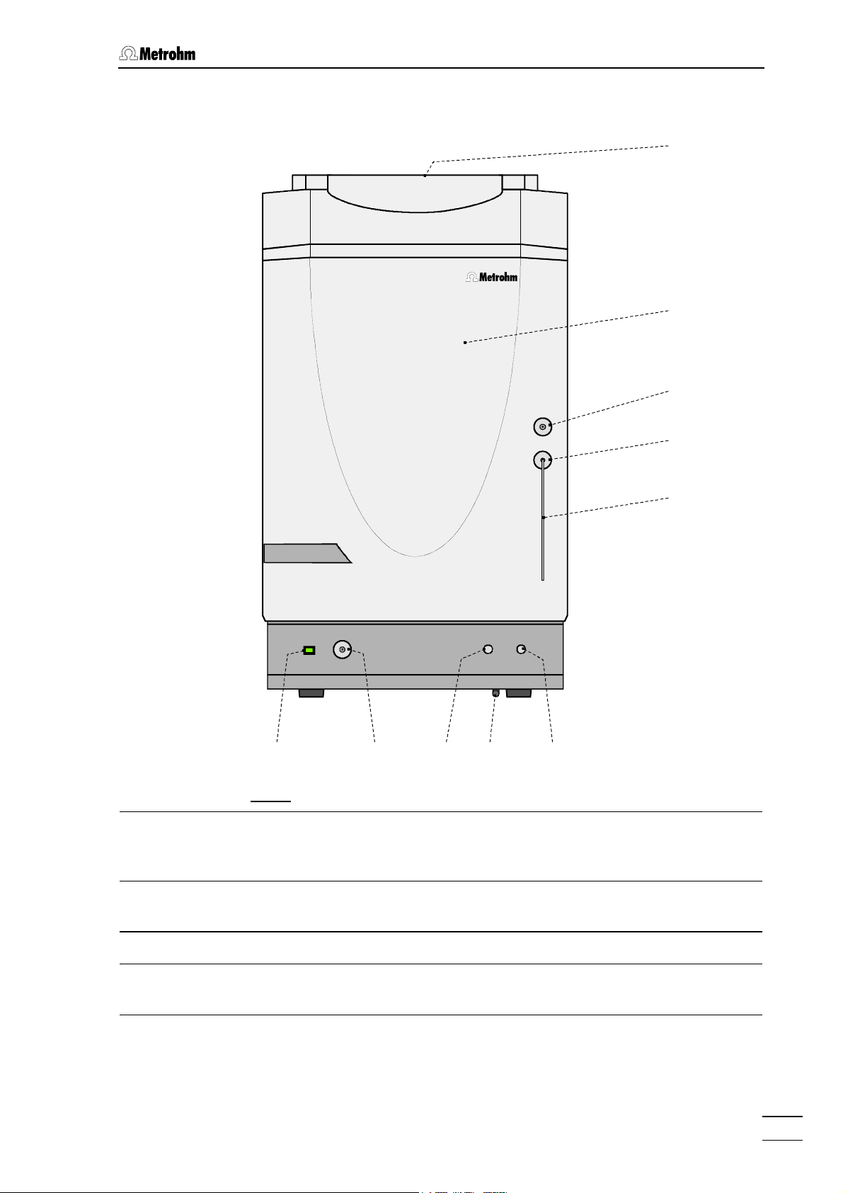
Fig. 1
: Front of the 761 Compact IC
1
Door to interior 6 Connection for drain tube
for discharge of spilled liquid from the
interior
2 Connection for 6.2816.020 Syringe
for aspiration of the sample
7 Feedthrough for capillaries
4
3 Feedthrough for aspirating tubing 8 Connection to purge valve
4 Aspirating tubing
for sample
5 Feedthrough for capillaries 10 Bottle rack
761 Compact IC
9 Mains pilot lamp
lit up when instrument switched on
for holding supply bottles with eluent,
regeneration solution, and rinsing
solution
3
Page 14
1 Introduction
15
15
11
13 14 13 10
12 12 11
Waste B
Waste A
15
16
17
15
25
24
23a
23
Type 1.761.
WARNING - Fire Hazard -
For continued protection replace only
with the same type and rating of fuse
Analog Output
Remote
Detector Block
RS 232
Made by Metrohm Herisau Switzerland
22
100-120V:
220-240V:
Transport security scre ws
f = 50-60 Hz
S = 100 VA
Fuse
1,0A(T)
0,5A(T)
18
19
20
21
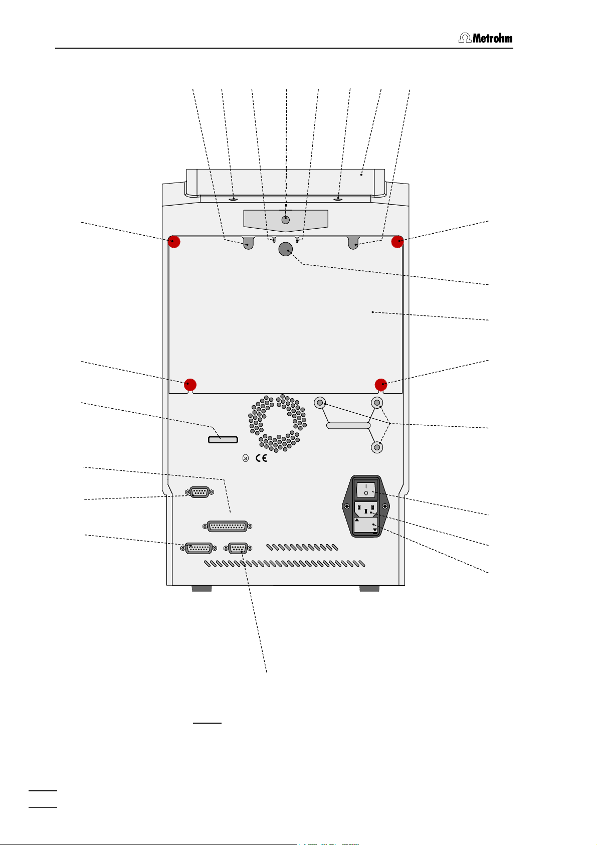
: Rear of the 761 Compact IC
Fig. 2
761 Compact IC
4
Page 15

1.2 Parts and controls
10 Bottle rack
for holding supply bottles with eluent,
regeneration solution, and rinsing
18 Transport security screws
to secure the pump head when the
instrument is transported
solution
Opening for detector cable 19 Mains switch
11
to switch instrument on and off:
I = ON 0 = OFF
12 Opening for inlet capillaries
for supply of eluent, regeneration
20 Mains connection plug
mains connection, see section 2.4
solution, and rinsing solution into the
inner compartment
13 Opening for outlet capillaries
for discharge of eluent, regeneration
21 Fuse holder
changing the fuses, see section 2.4
solution, and rinsing solution from the
inner compartment
14 Connection for drain tube
for discharge of spilled liquid from the
22 RS232 interface
connection of the PC
bottle rack
15 Knurled screw
for fastening the rear panel 17
16 Rear panel opening
(closed with plastic stopper) for
additional supply and discharge lines to
and from the inner compartment
17 Detachable rear panel
access to upper part of inner
compartment
23
Connection for detector block
23a
Analog output for measuring
signal
24 Remote interface
remote I/O lines for connection of
external devices
25 Serial number
761 Compact IC
5
Page 16
1 Introduction
46
45
44
43
42
41
40
39
38
1
26
27
28
29
30
31
4
27
32
36 35 34
37
: Interior of the 2.761.0010 Compact IC
Fig. 3
(with permanently attached accessories and
1.733.0110 Detector block)
761 Compact IC
6
33
Page 17

1.2 Parts and controls
1 Door to interior 36 Filter unit PEEK (6.2821.120)
Aspirating tubing
4
for aspirating the sample;
6.1803.020 PTFE tubing,
length L = 52 cm
26 Inlet capillary for injector
6.1831.010 PEEK capillary,
length L = 24 cm
27 Mounting rail
for 6.2027.0X0 column holder
28 Column connection capillary
6.1831.010 PEEK capillary,
length L = 30 cm
29 Sample loop 10 µL
6.1825.230 PEEK sample loop
30 Connection capillary to syringe
6.1803.020 PTFE tubing,
length L = 30 cm
37 Connection capillary
6.1831.010 PEEK capillary,
length L = 13 cm
38 Connection capillary
6.1831.010 PEEK capillary,
length L = 15 cm
39 Purge valve
40 Aspirating capillary
Connection for 6.1834.010 aspirating
tubing
41 Fastening screws
for pump head 42
42 Pump head (6.2824.100)
31 Rotary nipple for aspirating tube
for fixing the aspirating tube
43 Connection capillary
Connection pump head – purge
valve, fixed mounting
32 Injection valve
33 PEEK coupling (6.2744.040)
44 Connection capillary
in pump head, fixed mounting
45 Inlet capillary for detector block
PEEK capillary, fixed mounting
34 Leak detector 46 Detector block (1.732.0110)
35 Connection capillary
6.1831.010 PEEK capillary,
length L = 13 cm
761 Compact IC
7
Page 18
1 Introduction
46
45
44
43
42
41
40
39
38
1
26
27
28
29
47
30
31
4
27
32
48
36 35 34
37
: Interior of the 2.761.0020 Compact IC
Fig. 4
(with permanently attached accessories and
1.733.0110 Detector block)
761 Compact IC
8
33
53 52
5051
49
Page 19

1.2 Parts and controls
1 Door to interior 39 Purge valve
Aspirating tubing
4
for aspirating the sample;
6.1803.020 PTFE tubing,
length L = 52 cm
26 Inlet capillary for injector
6.1831.010 PEEK capillary,
length L = 24 cm
27 Mounting rail
for 6.2027.0X0 column holder
28 Column connection capillary
6.1831.010 PEEK capillary,
length L = 30 cm
29 Sample loop 20 µL
6.1825.210 PEEK sample loop
30 Connection capillary to syringe
6.1803.020 PTFE tubing,
length L = 30 cm
40 Aspirating capillary
Connection for 6.1834.010 aspirating
tubing
41 Fastening screws
for pump head 42
42 Pump head (6.2824.100)
43 Connection capillary
Connection pump head – purge
valve, fixed mounting
44 Connection capillary
in pump head, fixed mounting
45 Inlet capillary for detector block
PEEK capillary, fixed mounting
31 Rotary nipple for aspirating tube
46 Detector block (1.732.0110)
for fixing the aspirating tube
32 Injection valve
47 Suppressor module
(inlet and outlet capillaries are not
shown)
33 PEEK coupling (6.2744.040)
48 Tubing cartridge (6.2755.000)
for 6.1826.060 pump tubing
34 Leak detector 49 Contact pressure lever
for adjusting the contact pressure
35 Connection capillary
6.1831.010 PEEK capillary,
length L = 13 cm
50 Holding clamp
for locking the tubing cartridge into
place
36 Filter unit PEEK (6.2821.120) 51 Snap-action lever
for releasing the tubing cartridge
37 Connection capillary
6.1831.010 PEEK capillary,
52 Pump drive
roller head with contact rollers
length L = 13 cm
38 Connection capillary
6.1831.030 PEEK capillary,
length L = 20 cm
761 Compact IC
53 Mounting pin
for attaching the tubing cartridges
9
Page 20

1 Introduction
1.3 Information on the Instructions for Use
Please read through these Instructions for Use carefully before you put
the 761 Compact IC into operation. The Instructions for Use contain
information and warnings to which the user must pay attention in order
to assure safe operation of the instrument.
1.3.1 Organization
These 8.761.1063 Instructions for Use for the 761 Compact IC pro-
vide a comprehensive overview of the installation, startup procedure,
operation, fault rectification and technical specifications of this instrument. The Instructions for Use are organized as follows:
Section 1 Introduction
General description of instrument, parts and controls
and safety notes
Section 2 Installation
Installation of instrument, accessories,
and external devices
Section 3 Operating tutorial
Introduction to the operation using an example
Section 4 Operation
Detailed description of the operation
Section 5 Notes – Maintenance – Faults
Notes on ion chromatography, maintenance, fault rectification, diagnostic tests, validation
Section 6 Appendix
Technical data, standard equipment, options, warranty,
declarations of conformity, index
To find the required information on the instruments, you will find it an
advantage to use either the Table of contents or the Index at the
back.
As a supplement to the Instructions for Use, the Metrohm Monograph
8.732.2003 "Ion chromatography" is also supplied. This provides an
introduction to the theoretical fundamentals and general information on
separating columns and sample pretreatment.
The 8.732.2013 IC Applications Collection is also supplied; this contains all the Application Notes on the subject of ion chromatography.
Each of these applications can be carried out directly with the 761
Compact IC by loading the system file with the same name. The Applications Collection can be updated at any time by downloading the latest applications from the Internet under «www.metrohm.ch».
You will find detailed information on the separating columns available
from Metrohm and on special IC applications in the relevant "Applica-
tion Bulletins", which are available on request free of charge from your
Metrohm agency.
761 Compact IC
10
Page 21
1.3 Information on the Instructions for Use
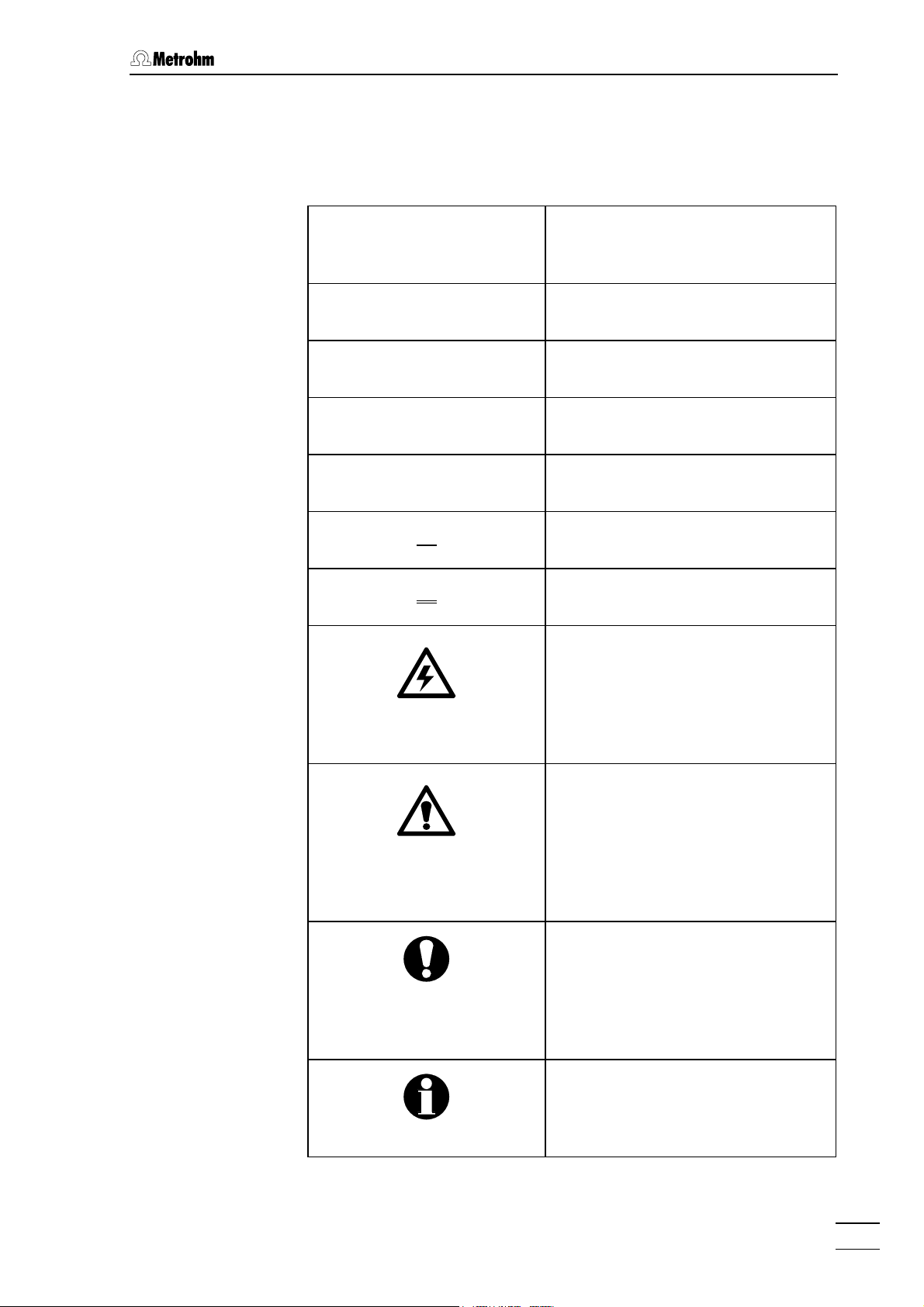
1.3.2 Notation and pictograms
The following notations and pictograms (symbols) are used in these Instructions for Use:
Range Menu item, parameter or entry
value
SYSTEM STATE Program window
<OK> Button
[ Ctrl ] Key
35 Part or control of 761
12 Part or control of 750
26 Part or control of 766
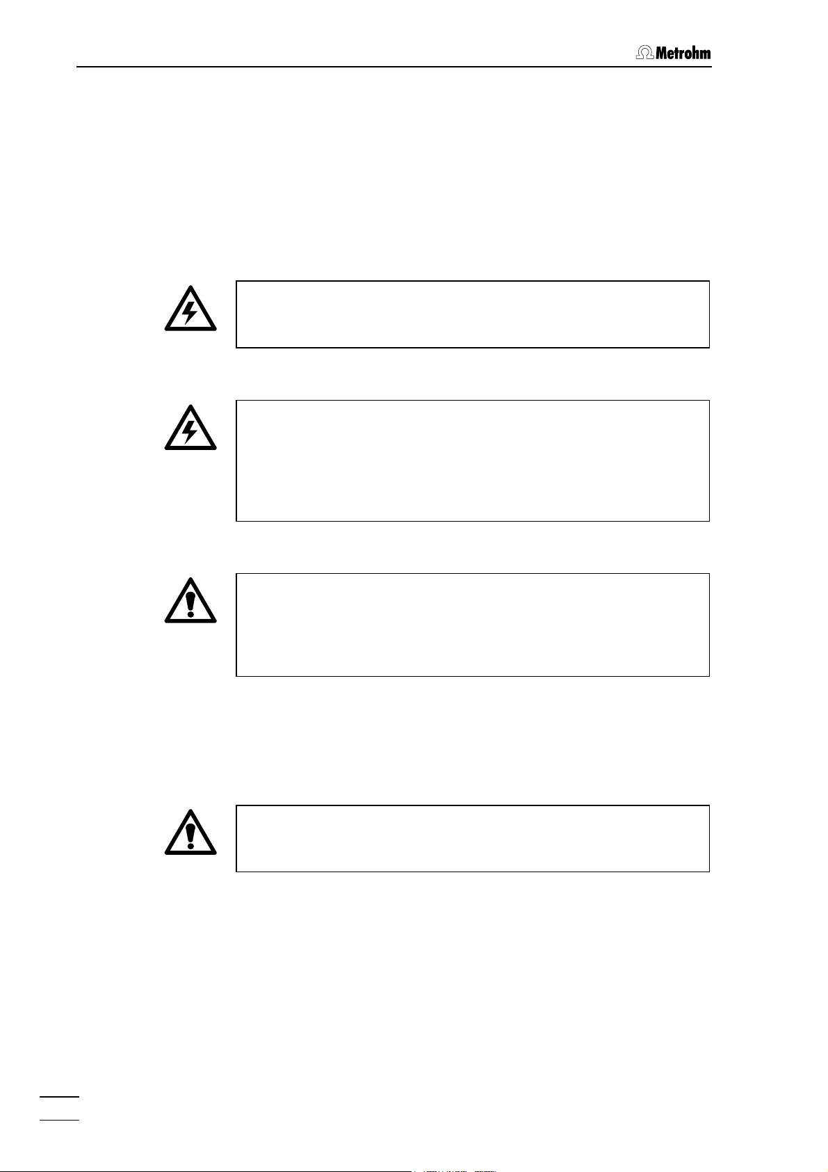
Hazard
This symbol draws attention to a
possible danger to life or of injury if
the associated directions are not
followed correctly.
Warning
This symbol draws attention to
possible damage to instruments or
instrument parts if the associated
directions are not followed correctly.
Caution
This symbol marks important
information. First read the associated directions before you continue.
761 Compact IC
Comment
This symbol marks additional
information and tips.
11
Page 22
1 Introduction
1.4 Safety notes
1.4.1 Electrical safety
While electrical safety in the handling of the 761 Compact IC is assured
in the context of the specifications IEC 1010-1 (protection class 1, degree of protection IP20), the following points should be noted:
• Mains connection
Setting of the mains voltage, checking the mains fuse and the
mains connection must be effected in accordance with the instruc-
tions in section 2.4.
• Opening the 761 Compact IC
If the 761 Compact IC is connected to the power supply, the instrument must not be opened nor must parts be removed from it, otherwise there is a danger of coming into contact with components which
are live. Hence, always disconnect the instrument from all voltage
sources before you open it and ensure that the mains cable is
disconnected from mains connection 20 !
• Protection against static charges
Electronic components are sensitive to static charging and can be
destroyed by discharges. Before you touch any of the components
inside the 761 Compact IC, you should earth yourself and any tools
you are using by touching an earthed object (e.g. housing of the
instrument or a radiator) to eliminate any static charges which exist.
1.4.2 General precautionary rules
• Handling of solvents
Check all lines of the IC system periodically for possible leaks. Follow
the relevant instructions regarding the handling of flammable and/or
toxic solvents and their disposal.
761 Compact IC
12
Page 23
2.1 Overview
2 Installation
2.1 Overview
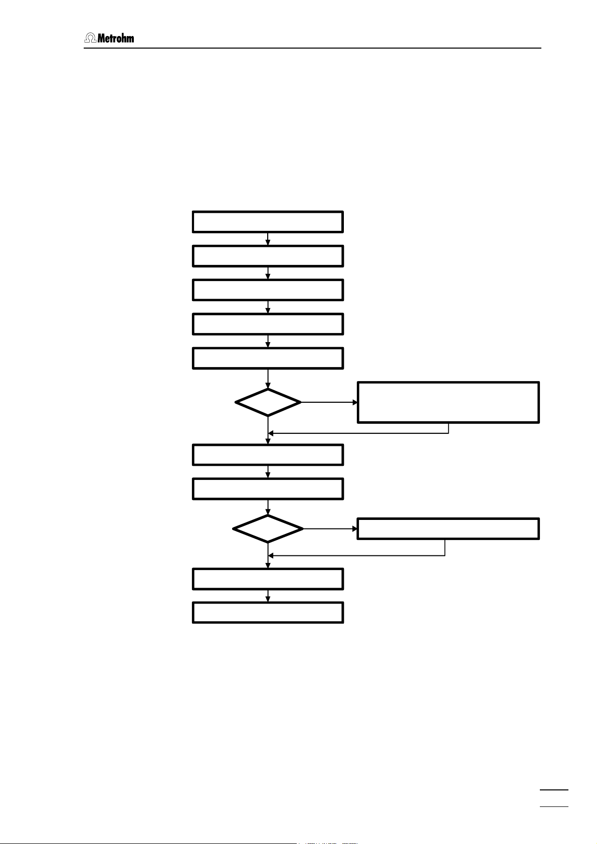
2.1.1 Flow chart
The following flow chart provides an overview of all installation work. You
will find more detailed information in the relevant sections.
Setting up sect. 2.2
Installing accessories sect. 2.3
Mains connection sect. 2.4
Connecting PC sect. 2.5
Connecting high pr. pump sect 2.6
Precolumn
No
Installing sample loop sect. 2.7.6
Connecting column sect. 2.7.7/8
Suppressor Connecting suppressor module sect. 2.8
No
Conditioning sect. 2.9
Connecting external devices sect. 2.10
Yes
Yes
Precolumn with cartridge head sect. 2.7.2
Precolumn with cartridge holder sect. 2.7.3
IC anion precolumn SUPERSEP sect. 2.7.4
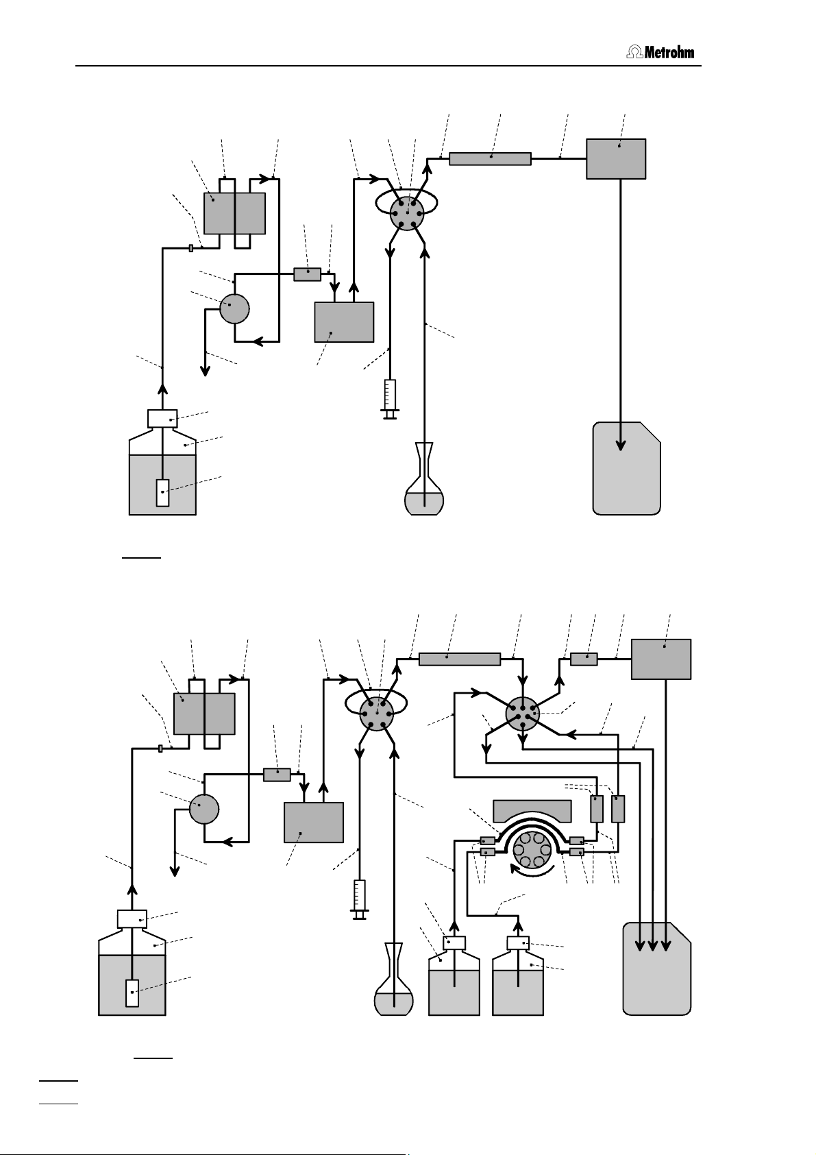
2.1.2 Connections in the 761 Compact IC
The two following illustrations show the internal connections in the 761
Compact IC in schematic form. The meanings of the various numbered
components are given in the detailed illustrations and descriptions in
sections 2.2 – 2.10.
761 Compact IC
13
Page 24
2 Installation
28 81 45 46
63
40
39
42
37
Eluent
44 43
38
66
67
68
36 35
60
26 29 32
30
Column
Injection valve
4
Sample
Detector
Waste
: Connecting diagram for 2.761.0010 Compact IC without suppressor
Fig. 5
44 43
28 81 96
26 29 32
97 33 45 46
42
Detector
98
100
40
36 35
Column
47
101
99
37
89
36
9191 93 95
63
39
66
38
60
30
90
102
103
92
4
67
102
68
H
OH2SO
Eluent
: Connecting diagram for 2.761.0020 Compact IC with suppressor
Fig. 6
761 Compact IC
14
Sample
4
2
103
Waste
Page 25
2.2 Setting up the instrument
2.2 Setting up the instrument
2.2.1 Packaging
The 761 Compact IC is supplied together with the separately packed
accessories in special packagings containing shock-absorbing foam
linings designed to provide excellent protection. The instrument itself is
packed in an evacuated polyethylene bag to prevent the ingress of
dust. Please store all these special packagings as only they assure
transport of the instrument free from damage.
2.2.2 Check
After receipt, immediately check whether the shipment is complete and
has arrived without damage (compare with delivery note and list of
accessories in section 6.2). In the case of transport damage, see
instructions in section 6.4.1 "Warranty".
2.2.3 Location
Position the instrument in the laboratory at a location convenient for operation, free from vibrations and protected against a corrosive atmosphere and contamination by chemicals.
To avoid disturbing temperature influences on the insulated column
compartment, the instrument must be protected against direct
sunlight.
2.3 Attaching the accessories
2.3.1 Connection of detector block
The metal-free 1.732.0110 Detector block belongs to the scope of
supply of the 761 Compact IC; it must be inserted in the instrument and
connected up. Proceed as follows:
1 Note the cell constant
• The cell constant c = XX,X /cm is printed on the rear of the
detector block. Note this value; it must subsequently be entered in the software in order to ensure that an exact display
of the conductivity is obtained (see section 2.5.3).
761 Compact IC
2 Install detector block
• Unscrew the four knurled screws 15 from the top rear panel
17 of the 761 Compact IC and remove rear panel (see Fig. 2).
• Position detector block 46 from the back in the space pro-
vided in the 761 Compact IC and push fully to the front (see
Fig. 3 and Fig. 4).
15
Page 26

2 Installation
• Insert the cable permanently attached to the detector block
46 in one of the openings 11 and the outlet capillary in one of
the openings 13 of the rear panel 17.
• Replace rear panel 17 and screw to the 761 Compact IC
using the four knurled screws 15.
3 Connect detector block
• Plug the gray connecting cable permanently attached to the
detector block 46 into connection 23 "Detector Block" of the
761 Compact IC and fasten to the instrument by tightening
the screws in the cable connector (see Fig. 2).
4 Connect waste container
• Lead the outlet capillary of the detector block 46 to a suffi-
ciently large waste container and fix in place.
2.3.2 Connection of syringe and aspirating tubing
For manual filling of the sample loop 29 mounted on the injection valve,
the 6.2816.020 Syringe and the PTFE aspirating tubing 4 already
screwed to the valve are needed. These accessories are mounted or
adjusted as follows:
1 Connect syringe
• Push 6.2816.020 Syringe (without needle) as far as it will go
into connection socket 2 (see Fig. 1).
2 Adjust aspirating tubing
• Loosen the rotary nipple 31 screwed onto the interior side of
feedthrough 3 (see Fig. 3 and Fig. 4).
• Pull PTFE aspirating tubing 4 (see Fig. 3 and Fig. 4) by hand
out of feedthrough 3 as far as desired.
• Retighten rotary nipple 31 on the interior side of feedthrough
3 to fix the aspirating tubing 4 in place.
2.3.3 Connection of the drain tube for the inner compartment
The 761 Compact IC has a connection at the front to which a drain tube
for discharged liquids in the inner compartment can be attached. Proceed as follows:
1 Connect drain tube
• Mount 6.1816.020 Silicone tubing on connection nipple 6
(see Fig. 1).
2 Lead drain tube to collecting vessel
• Lead the other end of the drain tube to a suitable collecting
vessel and fix in place.
761 Compact IC
16
Page 27
2.3 Attaching the accessories
2.3.4 Connection of the drain tube for bottle rack
The 761 Compact IC has a connection at the rear to which a drain tube
for discharged liquids in the bottle rack can be attached. Proceed as
follows:
1 Connect drain tube
• Mount 6.1816.020 Silicone tubing on connection nipple 14
(see Fig. 2).
2 Lead drain tube to collecting vessel
• Lead the other end of the drain tube to a suitable collecting
vessel and fix in place.
2.3.5 Connection of PEEK capillaries
For the connections between high-pressure pump and detector block
1
6.1831.010 PEEK capillaries (i.d. = 0.25 mm, e.d. =
which are connected using either 6.2744.010 PEEK compression fit-
tings (long) or 6.2744.070 PEEK compression fittings (short).
These PEEK connectors can also be used to connect 6.1822.010 PTFE
microcapillaries (i.d. = 0.3 mm). Proceed as follows:
/16") are used
Capillaries fitted with new connectors must have a perfectly flat cut
surface. To cut PEEK or PTFE capillaries it is best to use the
6.2621.080 Capillary tubing cutter.
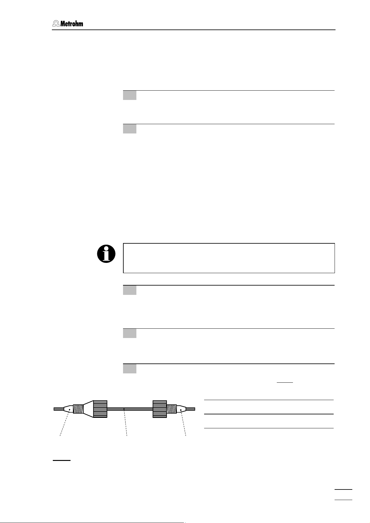
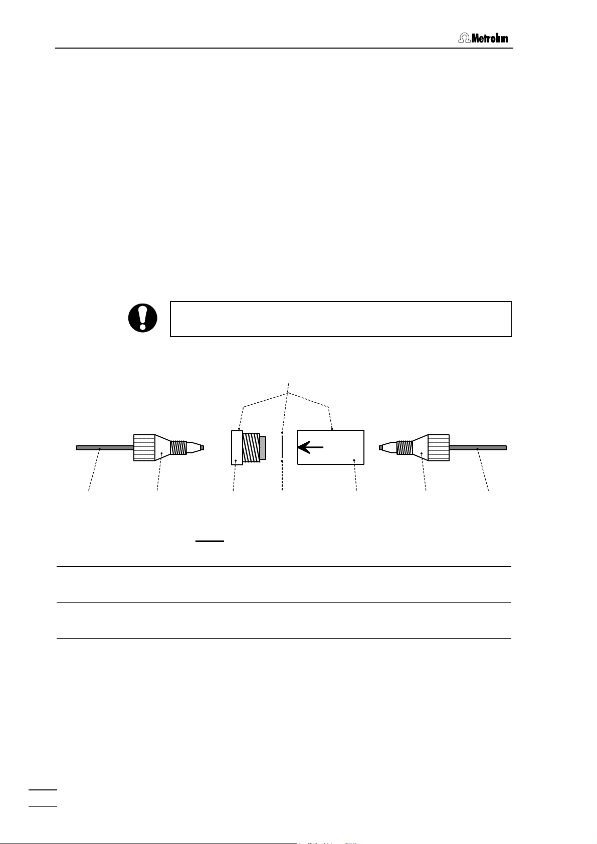
1 Mount compression fitting
Slide a compression fitting 54 (6.2744.010) or a compression
fitting 55 (6.2744.070) over the end of the capillary 56 to be
fastened as shown in Fig. 7.
2 Insert capillary in connection
Push capillary end in the corresponding connection as far as it
will go (to avoid dead volume).
3 Tighten compression fitting
Tighten compression fitting 54 or 55 by hand (never use tools).
54 Compression fitting (6.2744.010)
55 Compression fitting (6.2744.070)
54 56 55
Fig. 7
: Connectors for capillaries
761 Compact IC
56 Capillary
6.1831.010 PEEK capillary or
6.1822.010 PTFE microcapillary
17
Page 28
2 Installation
2.3.6 Filter unit PEEK
One 6.2821.120 Filter unit PEEK (see Fig. 8) is already installed be-
tween the high-pressure pump and the injection valve at the 761 Compact IC. This filter unit serves to avoid contamination by abrasive particles of the piston seals.
The two other filter units PEEK supplied with the 2.761.0020 Compact
IC (with suppressor) are installed between the pump tubings of the
peristaltic pump and the inlet capillaries for regeneration and rinsing solution (see section 2.8.2). These filter units serve to protect the suppressor module from foreign particles and bacterial growth.
The Filter unit PEEK 36 consists of the filter-housing 59, the filter-screw
57 and the 6.2821.130 filter 58. For the connection of capillaries 56
PEEK compression fittings 54 (6.2744.010 or 6.2744.070) must be
used. New filters 58 are available as an option with the ordering number
6.2821.130 (set of 10).
For the connection of the filter unit, please note the flow direction
arrow printed on the housing.
36
56 54
36 Filter unit PEEK (6.2821.120) 57 Filter-Screw of Filter Unit
54 Compression fitting (6.2744.010) 58 Filter 6.2821.130
56 Capillary
6.1831.010 PEEK capillary or
6.1822.010 PTFE microcapillary
57
Fig. 8
: 6.2821.120 Filter unit PEEK
58
Part of 6.2821.120 Filter unit
Part of 6.2821.120 Filter unit
59 Filter-Housing of Filter Unit
Part of 6.2821.120 Filter unit
59 54 56
761 Compact IC
18
Page 29

2.4 Mains connection
2.4 Mains connection
Follow the instructions below for connecting to the power supply. If
the instrument is operated with a mains voltage set wrongly and/or
wrong mains fuse, there is a danger of fire!
2.4.1 Setting the mains voltage
Before switching on the 761 Compact IC for the first time, check that
the mains voltage set on the instrument (see Fig. 9) matches the local
mains voltage. If this is not
on the instrument as follows:
1 Disconnect mains cable
Disconnect mains cable from mains connection plug 20 of the
761 Compact IC.
the case, you must reset the mains voltage
2 Remove fuse holder
Using a screwdriver, loosen fuse holder 21 below the mains
connection plug 20 and take out completely.
3 Check and change fuse if necessary
Carefully take the fuse installed for the desired mains voltage out
of fuse holder 21 and check its specifications (the position of the
fuse in the fuse holder is marked by the white arrow imprinted
next to the mains voltage range):
100…120 V 1.0 A (slow-blow) Metrohm No. U.600.0016
220…240 V 0.5 A (slow-blow) Metrohm No. U.600.0013
4 Insert fuse
Change fuse if necessary and reinsert in fuse holder 21.
5 Install fuse holder
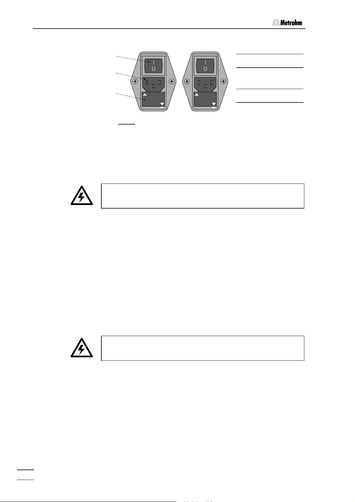
Depending on the desired mains voltage, insert fuse holder 21
in the 761 Compact IC so that the corresponding mains voltage
range can be read normally and the adjacent white arrow points
to the white bar imprinted below the fuse holder (see Fig. 9).
761 Compact IC
19
Page 30
2 Installation
100 – 120 V 220 – 240 V
2.4.2 Fuses
19
19 Mains switch
20
21
220 - 240 V
Fig. 9
: Setting the mains voltage
100 - 120 V
100 - 120 V
One of the two fuses 1 A/slow-blow for 100…120 V or 0.5 A/slow-blow
for 220…240 V is installed in fuse holder 21 of the 761 Compact IC as
standard.
Ensure that the instrument is never put into operation with fuses of
another type, otherwise there is danger of fire!
For checking or changing fuses, process as described in section 2.4.1.
220 - 240 V
20 Mains connec-
tion plug
21 Fuse holder
2.4.3 Mains cable and mains connection
Mains cable
The instrument is supplied with one of three mains cables
• 6.2122.020 with plug SEV 12 (Switzerland, …)
• 6.2122.040 with plug CEE(7), VII (Germany, …)
• 6.2133.070 with plug NEMA 5-15 (USA, …)
which are three-cored and fitted with a plug with an earthing pin. If a different plug has to be fitted, the yellow/green lead (IEC standard) must
be connected to protective earth (protection class 1).
Any break in the earthing inside or outside the instrument can make it
a hazard!
Mains connection
Plug the mains cable into mains connection plug 20 of the 761 Compact IC (see Fig. 9).
2.4.4 On/off switching of the instrument
The 761 Compact IC is switched on and off using mains switch 19.
When the instrument is switched on, the mains pilot lamp 9 lights up.
761 Compact IC
20
Page 31

2.5 Connection to the PC
2.5 Connection to the PC
2.5.1 Connecting cable
Always switch off 761 Compact IC and PC before you connect the two
instruments with the 6.2134.100 Cable.
Connect the RS232 interface 22 at the 761 Compact IC to one of the
serial COM ports at the PC using the 6.2134.100 Cable (9 pin/9 pin). If
only a 25-pin COM interface is available on the PC then the 6.2125.110
Adapter cable or a commercially available adapter must be used.
2.5.2 Software installation
These Instructions for Use describe the operation of a single 761
Compact IC connected to a PC. If several instruments should be
operated simultaneously with one PC, the «IC Net 2.0» PC program
must be installed for this purpose (details see Instructions for Use for
«IC Net»).
The PC program «761 Compact IC 1.1» is required for the operation of
the 761 Compact IC; this is contained on the 6.6030.013 CD included in
the accessories. This program runs under Windows 95, Windows 98
and Windows NT operating systems and is installed as follows:
1 Install program
• Insert 6.6030.013 Installation CD into CD drive.
• Select
installation CD and click on
<Start> and Run. Browse for the setup.exe file on the
<OK>. Follow the instructions
given in the setup program.
The software package will be installed in the desired direc-
tory. Icons are created in the program folder and in the
startup folder. In addition to the program files, the following
folders are installed:
Data Folder for storage of chromatogram files
*.chw) and batch reprocessing files (*.bar)
(
Devices Folder for storage of device files (*.dev)
Methods Folder for storage of method files (*.mtw)
Reports Folder for storage of report files (*.txt)
and graphic files (
Systems Folder with subfolders with system files
*.smt) and sample queue files (*.que).
(
*.wmf)
761 Compact IC
2 Registration
• Please send us your 8.761.8007 Registration card as soon as
possible. Only registered users will get updated program versions at a special price.
21
Page 32
2 Installation
The installed files (incl. system and method files) are generally not
write-protected. To prevent these files from being deleted by mistake,
switch on the write-protection or make a backup copy in another
directory.
2.5.3 Basic settings
When the program is started for the first time several basic settings
must be made for the 761 Compact IC. Proceed as follows:
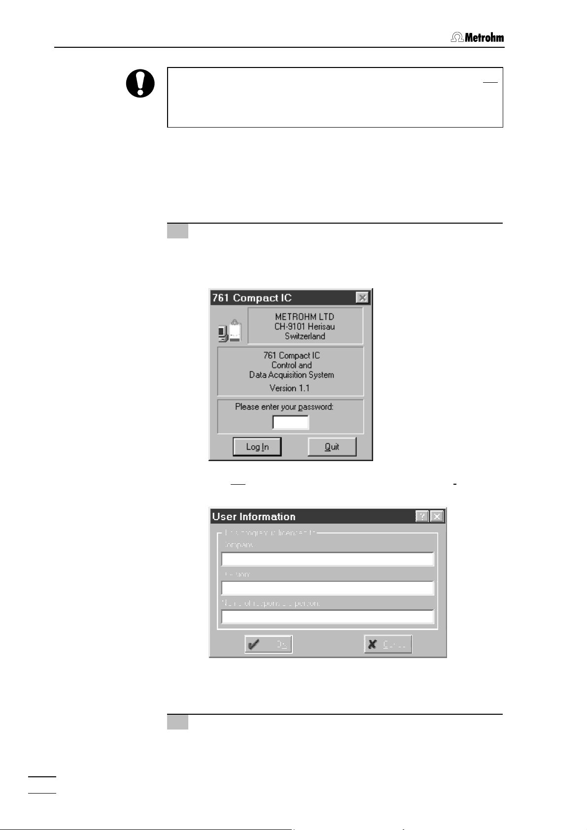
1 Start program
• Double-click the software icon to start the program. The
program window with the opening picture is opened and the
Log In window appears on the screen:
• Do not
enter any password here, just click on <Log In>. The
following window appears:
• Enter company, division and name and click on
<OK>. This
window appears only one time after software installation.
2 COM port settings
This step must only be carried out if a different COM interface
from COM1 is used for connection to the 761 Compact IC.
761 Compact IC
22
Page 33
2.5 Connection to the PC
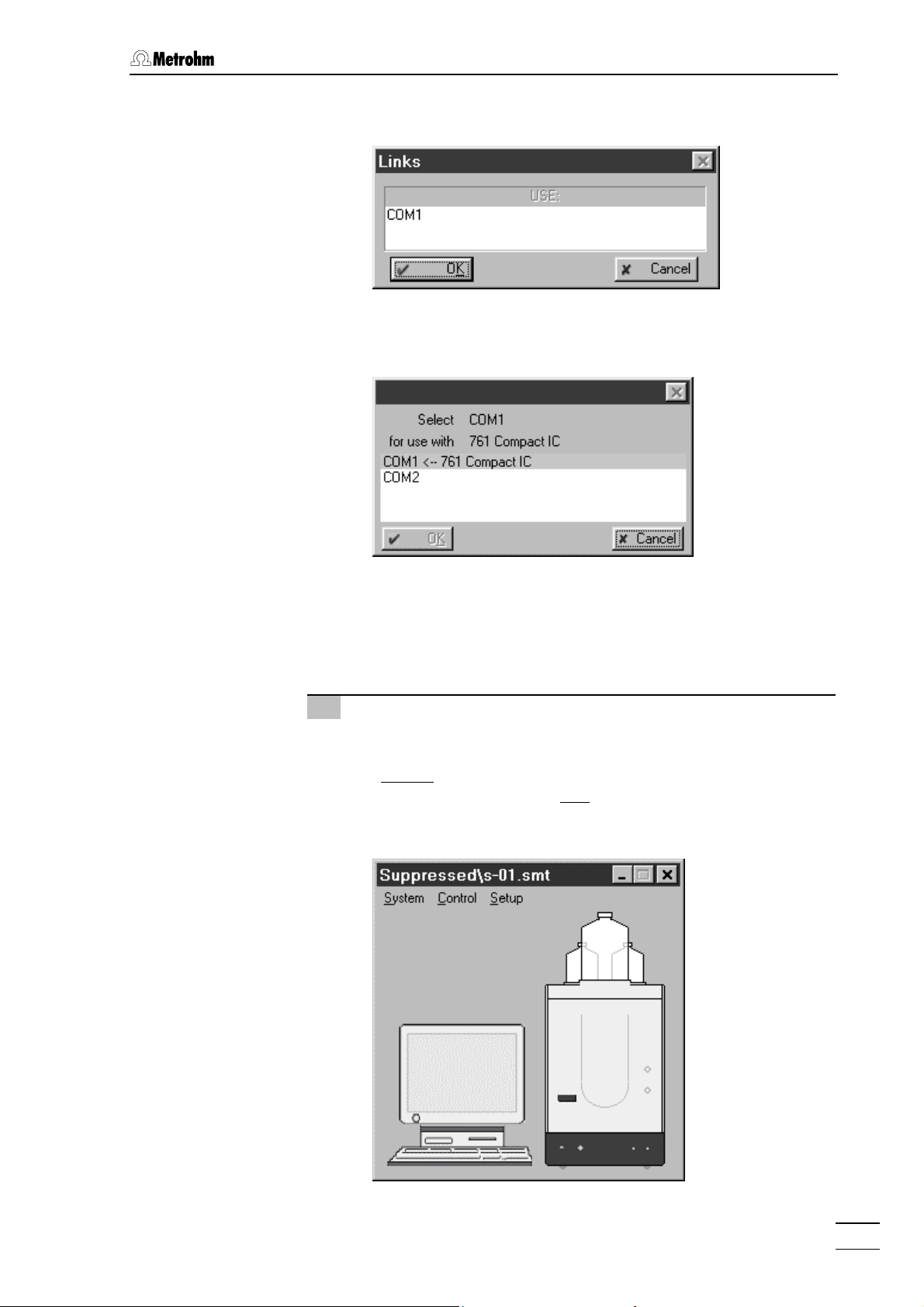
• Click on Options / 761 Compact IC:COM1 to open the Links
window:
• Click on
Change menu item to open the following window listing all
COM1 using the right mouse button and select the
available COM ports at the PC:
• Select the desired COM port to which the 761 Compact IC
has been connected and click on
<OK>. The window is
closed.
• Close the
Links window by clicking on <OK>.
3 Open a system
• Click on File / Open / System in the main window. Open either
the subfolder
without
suppressor) or the subfolder Suppressed (for
2.761.0020 Compact IC with
file
n-01.smt or s-01.smt and click on <Open>. The correspond-
Non-suppressed (for 2.761.0010 Compact IC
suppressor). Select the system
ing system window is opened:
761 Compact IC
23
Page 34
2 Installation
• Select the Connect to workplace menu item of the Control menu
in this window.
• If the connection between PC and Compact IC is working the
message
'#####' not found! Create?
create the configuration file
Hardware settings file for 761 unit with serial number
will appear. Click <Yes> in order to
#####.761 for this instrument.
• If the connection between PC and Compact IC does not work
then the message
[ COM# ]]
appears in the SYSTEM STATE window. In this case
Detection of hardware failed[761 Compact IC
check whether the instrument has been switched on, whether
the connection cable is connected up properly and whether
the COM interface has been set correctly (see point 2). Then
repeat point 3.
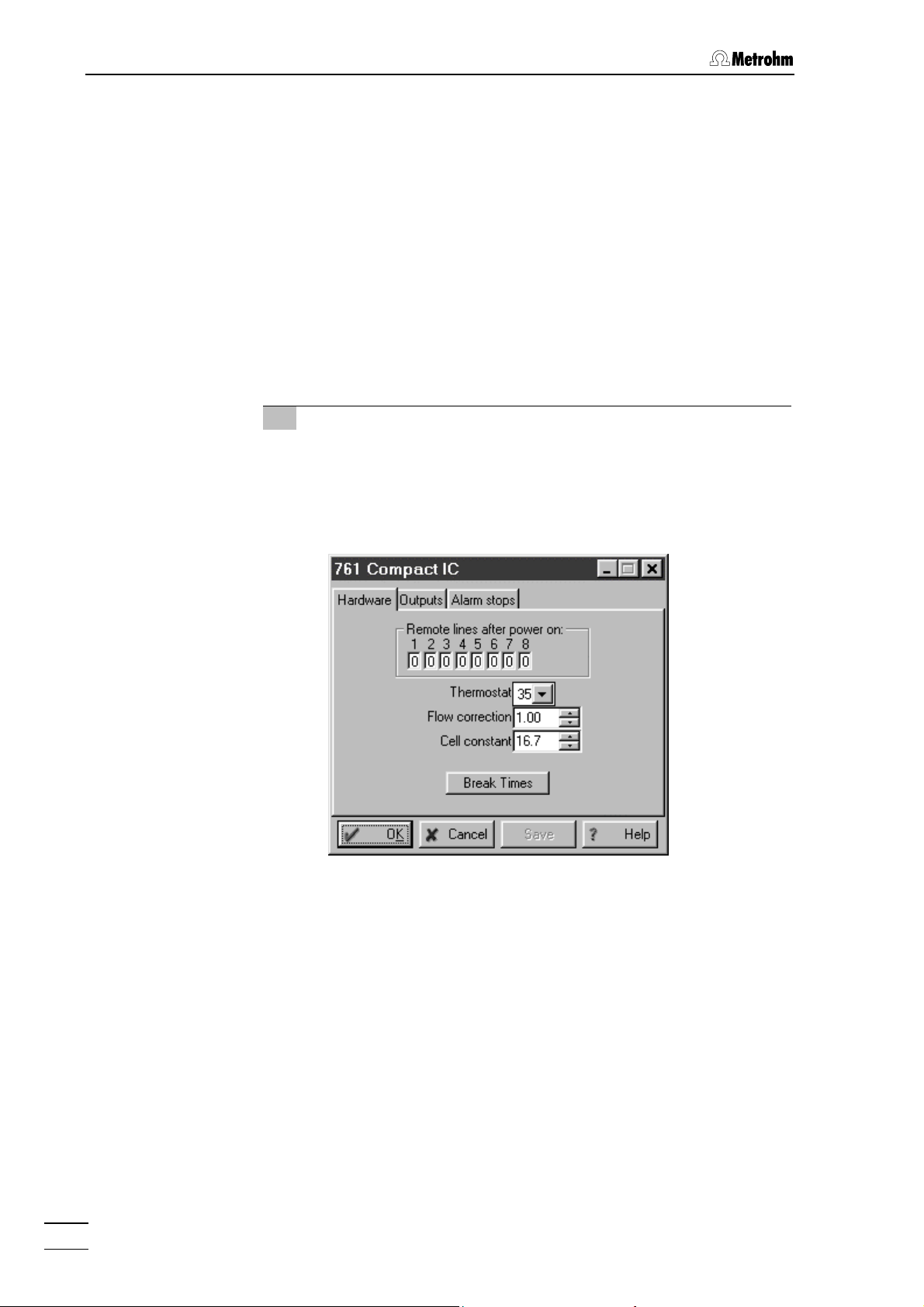
4 Hardware settings
Of the general hardware settings only the input of the cell constant
is described. Standard settings can normally be used for all other
parameters.
• Click the 761 icon using the right mouse button and select
Hardware item. The Hardware settings window is opened:
the
• In the
Cell constant field enter the cell constant which is printed
on the 1.732.0110 Detector block (see section 2.3.1).
• Click on
<OK> to close the window and save the settings.
761 Compact IC
24
Page 35
2.6 High-pressure pump
2.6 High-pressure pump
In order to avoid damage to the pump it must never be operated dry.
Each time that the pump is switched on always first check that the
eluent supply has been connected up correctly and that sufficient
eluent is present in the eluent bottle.
2.6.1 Removing the transport security screws
In order to prevent the pump drive from being damaged during transport the pump head is fitted with three transport security screws 18 (see
Fig. 2). These transport security screws must be removed before the
high-pressure pump is started up. Also remove the red sticker attached
to the pump head.
In order to avoid damage to the pump head these three security
screws should be attached to the pump head each time that it is to be
transported.
2.6.2 Installing the pulsation dampener
To protect the column material against pressure drops caused by the
injector, the 6.2620.150 Pulsation dampener MF has to be installed
between the high-pressure pump and the injection valve of the 761
Compact IC. Proceed as follows (see Fig. 10):
1 Install pulsation dampener
• Position the pulsation dampener 60 in the interior of the 761
Compact IC on the base.
2 Connection to the pump
• Unscrew PEEK capillary 35 of coupling 33 and attach it to
connection 62 of the pulsation dampener 60.
3 Connection to injection valve
• Unscrew PEEK capillary 26 of coupling 33 and attach it to
connection 61 of the pulsation dampener 60.
761 Compact IC
The pulsation dampener is filled with isopropanol and must be rinsed
with eluent before connection to a separating column (see section
2.6.4).
The 6.2620.150 Pulsation dampener can be operated in both directions.
25
Page 36
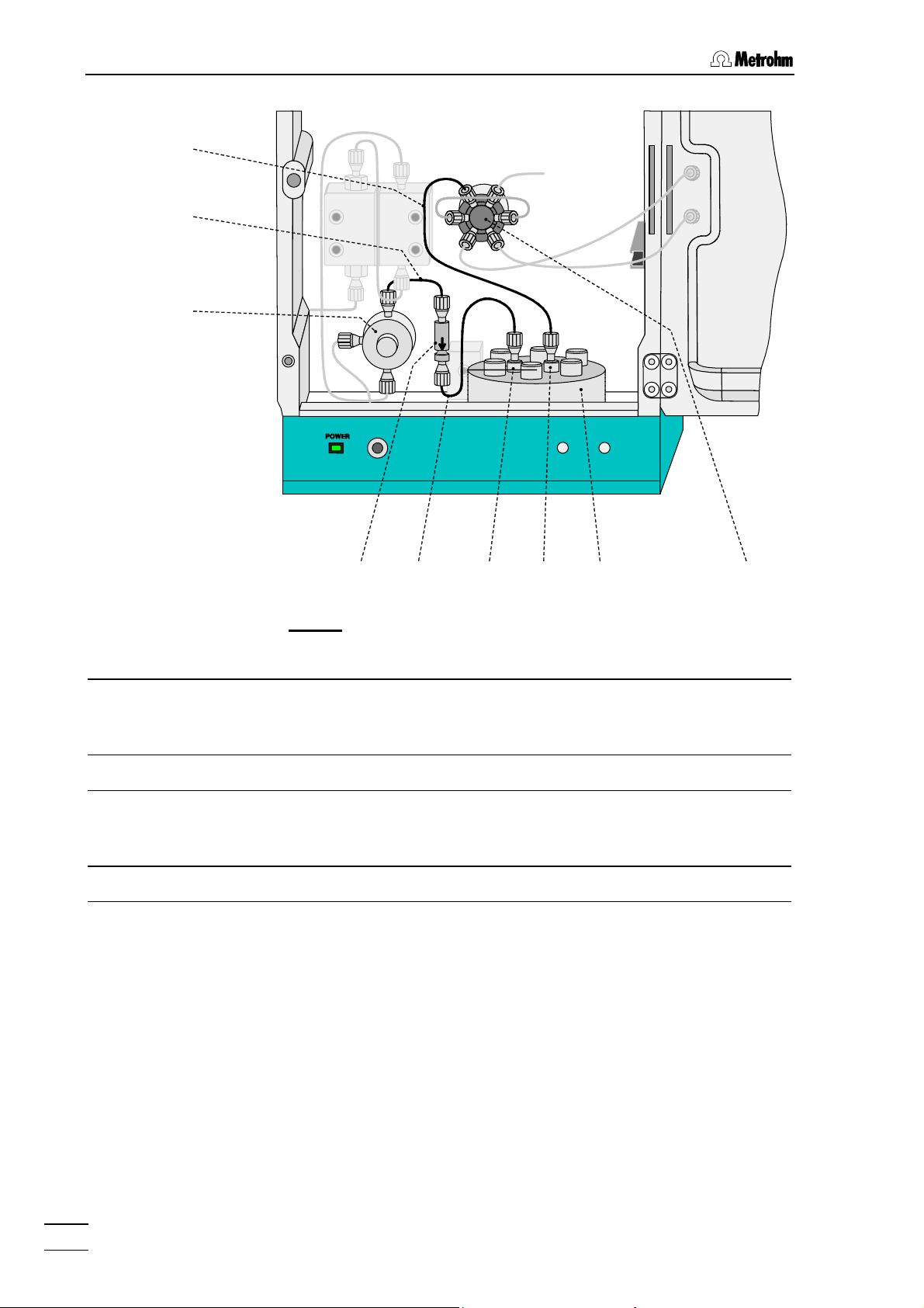
2 Installation
26
37
39
36 35 62
Fig. 10
Inlet capillary for injector
26
6.1831.010 PEEK capillary,
length L = 24 cm
32 Injection valve 60 Pulsation dampener (6.2620.150)
35 Connection capillary
6.1831.010 PEEK capillary,
length L = 13 cm
36 Filter unit PEEK (6.2821.120) 62 Connection to purge valve
37 Connection capillary
6.1831.010 PEEK capillary,
length L = 13 cm
: Connection of the pulsation dampener
39 Purge valve
61 Connection to injection valve
6061
32
761 Compact IC
26
Page 37
2.6 High-pressure pump
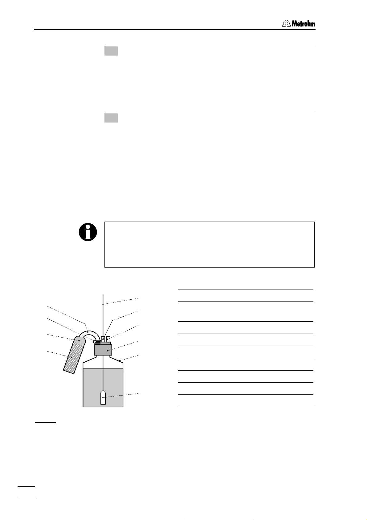
2.6.3 Connecting the eluent bottle
The eluent supply line from the storage bottle to the high-pressure
pump is connected as follows (see Fig. 11):
Only degassed (with N
, He or vacuum) and microfiltered (0.45 µm
2
filter) eluents should be used!
The 6.1608.070 Eluent bottle (2 L) supplied is not suitable for
vacuum degassing. Use a pressure-resistant container for this.
Care must be taken that the eluent used is freely miscible with any
solvent remaining in the pump head (the pump head leaves the
factory filled with either isopropanol or methanol/water). If this is not
the case then the pump must first be rinsed with a solvent which is
miscible with both the previous eluent and the following eluent (e.g.
acetone).
1 Prepare eluent bottle
• Prepare, microfilter (0.45 µm microfilter) and degas (with N2,
He, or vacuum) the suitable eluent for the required application
and separating column.
• Fill eluent into eluent vessel 67 (clear glass, 2 L).
• Place eluent bottle 67 at the front in bottle holder 10 on the
761 Compact IC (see Fig. 1).
2 Install bottle attachment
• Firmly screw threaded stopper 65 (6.1446.040; part of
6.1602.160) into the smaller threaded opening (M6) of bottle
attachment 66 (6.1602.105; part of 6.1602.160).
• Firmly screw aspirating filter 68 onto aspirating tubing 63.
• Pull the other end of aspirating tubing 63 through the larger
threaded opening (M8) of bottle attachment 66 from below.
• Push O-ring (E.301.0021; part of 6.1602.160) over the free
end of aspirating tubing 63 and move it towards bottle attachment 66.
• Push tubing nipple 64 (4.420.4300; part of 6.1602.160) over
the free end of aspirating tubing 63, move it as far as required towards bottle attachment 66 and screw it loosely in
the larger opening of bottle attachment 66.
• Insert aspirating tubing 63 with screwed-on aspiration filter 68
into eluent bottle 67 and screw bottle attachment 66 onto
eluent bottle 67.
• Pull aspirating tubing 63 so far through the opening of tubing
nipple 64 that aspirating filter 68 is touching the bottom of
eluent bottle 67.
• Fix aspirating tubing 63 in place by screwing shut tubing
nipple 64.
761 Compact IC
27
Page 38
2 Installation
3 Mount CO2 absorber tube
• First place a piece of cotton wool 70 followed by CO2 ab-
sorber 69 (e.g. Merck soda-lime pellets with indicator, no.
6839.1000) in the large opening of absorber tube 72 and then
close it with the plastic lid.
• Fasten absorber tube 72 to bottle attachment 66 with the aid
of SGJ clip 71.
4 Connect aspirating tubing to pump
• Insert the free end of aspirating tubing 63 into one of the
openings 12 in the interior of the 761 Compact IC (see Fig. 2).
• Pull aspirating tubing 63 sufficiently far into the interior of the
761 Compact IC, cut off to the required length and push at
least 5 mm of it onto aspirating capillary 40 (see Fig. 3 and
Fig. 4) of the high-pressure pump (it may be necessary to use
emery paper).
• If necessary, fix aspirating tubing 63 in the required position
in the interior with the aid of the Y.107.0150 self-adhesive
strap.
72
71
70
69
Fig. 11
Instead of threaded stopper
which belongs to the 6.1602.160 Bottle attachment accessories can
be used together with the included second E.301.0021 O-ring for
recycling operation (see section 5.2.3), in which the outlet capillary
from the detector block is led back into eluent bottle
63
64
65
66
67
68
: Connection of eluent bottle
65
, the 4.420.0311 Tubing nipple (M6)
67
.
63 Aspirating tubing (6.1834.010)
64 Tubing nipple (4.420.4300; M8)
with E.301.0021 O-ring
65 Threaded stopper (6.1446.040; M6)
66 Bottle attachment (6.1602.105)
67 Eluent bottle (6.1608.070)
68 Aspirating filter (6.2821.090)
69 CO2 absorber
70 Cotton wool
71 SGJ clip (6.2023.020)
72 Absorber tube (6.1609.000)
761 Compact IC
28
Page 39
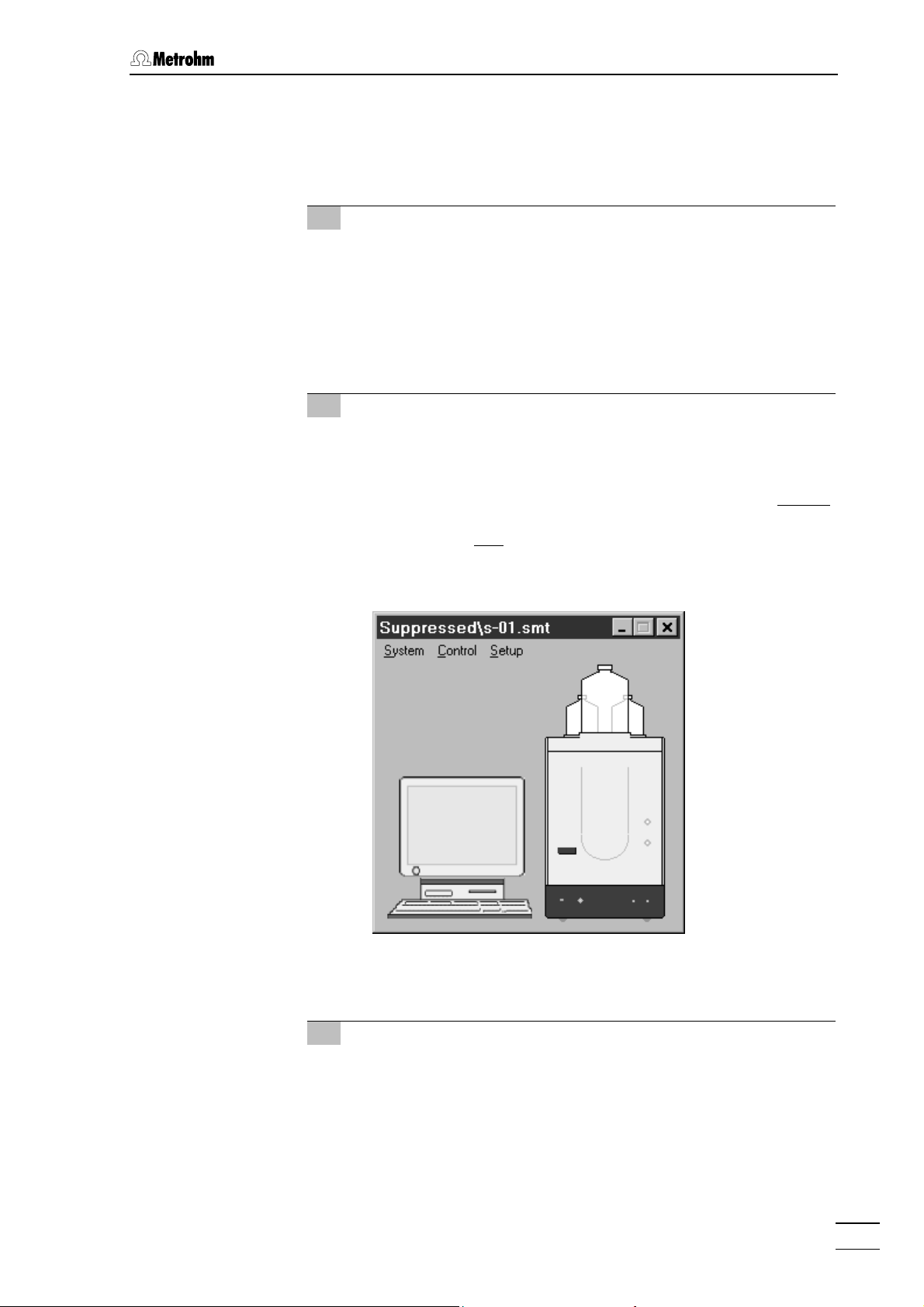
2.6 High-pressure pump
2.6.4 Deaerating the pump and rinsing the pulsation dampener
The first time that it is started up the high-pressure pump must be
deaerated. Proceed as follows:
1 Prepare for deaeration
• Open the rotary knob on purge valve 39 by approx. ½ turn in
the counterclockwise direction (see Fig. 3 and Fig. 4).
• Remove the plastic stopper from connection 8 on the front
panel of 761 Compact IC (see Fig. 1).
• Push 6.2816.020 Syringe (without needle) into connection 8
until the stop is reached.
2 Open and connect system
• Start the «761 Compact IC» PC program, if it has not been
already been started (see section 2.5.3).
• Select
subfolder
suppressor) or the subfolder
Compact IC with
or
window is opened:
File / Open / System in the main window. Open either the
Non-suppressed (for 2.761.0010 Compact IC without
Suppressed (for 2.761.0020
suppressor). Select the system file n-01.smt
s-01.smt and click on <Open>. The corresponding system
761 Compact IC
• Select the
Connect to workplace item of the Control menu in this
window.
3 Set flow rate to 2 mL/min
• Double-click the 761 icon in the system window to open the
window for manual control of the 761 Compact IC (see below).
• Set the flow rate to
• Click to
<Send to unit> to send this value to the 761 Compact
2 mL/min in the Flow field.
IC.
29
Page 40
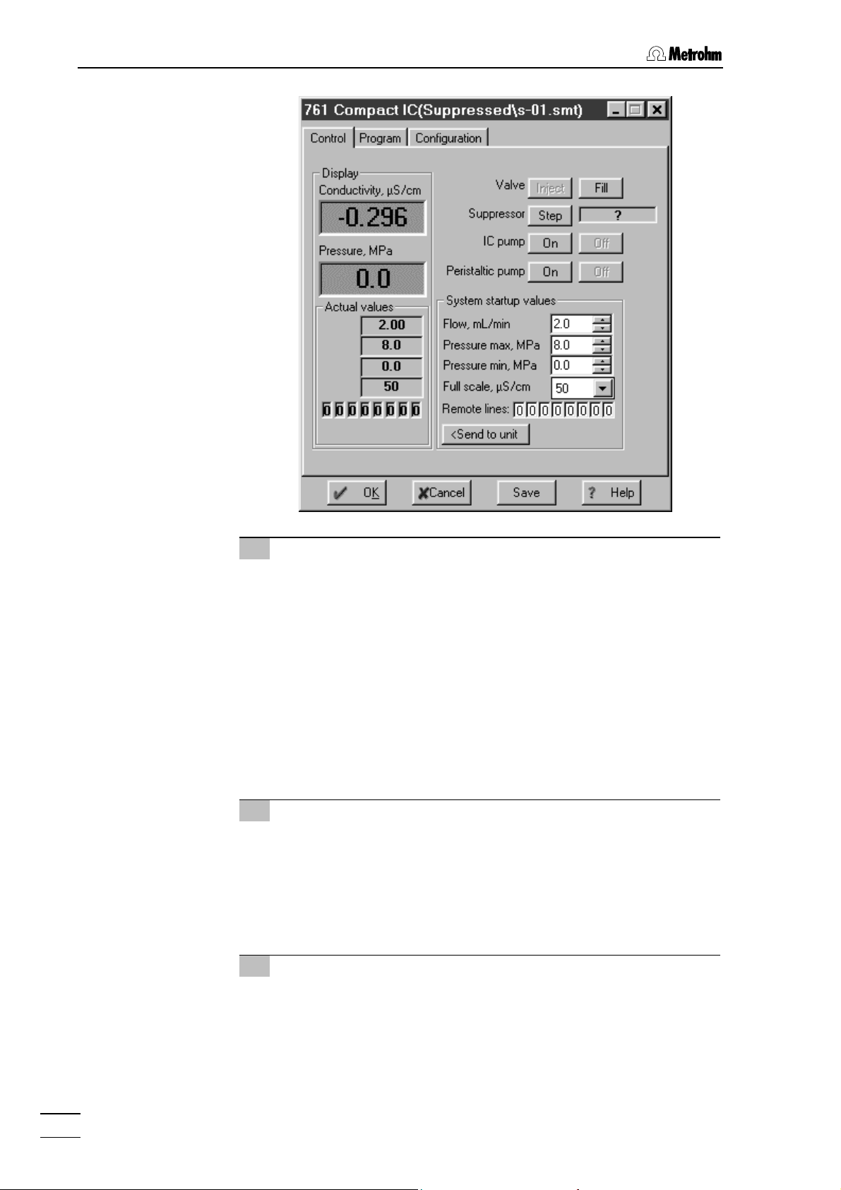
2 Installation
4 Deaerate pump
• Make sure that the aspirating tubing 63 for the high-pressure
pump has been immersed into the eluent.
• Click the
<On> button for IC pump to switch on the high-
pressure pump.
• Use the syringe inserted into connection 8 to aspirate air until
eluent flows into the syringe.
• Click the
<Off> button for IC pump to switch off the high-
pressure pump.
• Close the rotary knob on purge valve 39 by turning it in a
clockwise direction (see Fig. 3 and Fig. 4).
• Remove the syringe from connection 8.
5 Rinse pulsation dampener
• Place a beaker beneath the column connection capillary 28.
• Click the
<On> button for IC pump to switch on the high-
pressure pump and rinse the pulsation dampener 60 filled
with isopropanol for ca. 10 min with eluent.
• Click the
<Off> button for IC pump to switch off the high-
pressure pump.
6 Reduce flow rate
• Reset the original flow rate under Flow (e.g. 0.5 mL/min).
• Click
<Send to unit> to send this value to the 761 Compact IC.
761 Compact IC
30
Page 41
2.7 Precolumns and separating columns
2.7 Precolumns and separating columns
2.7.1 General information on precolumns
The use of easily exchangeable precolumns protects the separating
columns and prolongs their lifetime. The precolumns available from
Metrohm (see section 6.3.2) are either real precolumns or precolumn
cartridges, which are used together with the 6.2821.040 Cartridge head
or the 6.2828.010 Precolumn cartridge holder.
New IC precolumns are normally filled with solution and sealed at both
ends. Before the precolumn is installed in the system, it must be
ensured that this solution is freely miscible with the eluent used
(check manufacturer's specifications).
2.7.2 Precolumns with cartridge head
The 6.1005.020, 6.1005.040, 6.1005.050, 6.1007.010 and 6.1010.010
Precolumn cartridges are installed in the 6.2821.040 Cartridge head as
follows (see Fig. 12):
1 Prepare separating column
• Remove end caps from separating column 81.
• Unscrew fastening screw from column inlet.
• Take steel connector 74 for ferrule out of fastening screw.
2 Install cartridge
• Remove end caps for precolumn cartridge 77 (the steel mesh
76 and gaskets 75 are already installed in the cartridge).
• Mount steel spacer 78 on Manufit pressure screw 80 (the
steel mesh 79 and gaskets 75 are already installed in the
pressure screw).
• Mount precolumn cartridge 77 on the steel spacer 78 (com-
ply with flow direction if specified on the precolumn).
• Screw Manufit pressure screw 80 firmly to separating column
81.
• Mount steel connector 74 for ferrule on the inlet side of the
precolumn cartridge 77.
• Screw on Manufit housing 73 with Manufit pressure screw 80.
761 Compact IC
31
Page 42

2 Installation
7473 75 76 77 76 75 78 755428 79 80 81
Fig. 12
28 Column connection capillary from
injector
54 Compression fitting (6.2744.010) 78 Steel spacer (6.2821.080)
73 Manufit housing 79 4 Steel meshes (6.2821.020)
74 Steel connector
(of IC separating column)
75 PTFE gasket (6.2821.010) 81 IC separating column
76 2 Steel meshes (6.2821.020)
: Installation of precolumn cartridges with cartridge head
Precolumn cartridge
77
80 Manufit pressure screw
3 Connect precolumn
• Fit PEEK compression fitting 54 to the column connection
capillary 28 mounted on the injection valve (see section
2.3.5).
• Screw column connection capillary 28 to Manufit housing 73.
The precolumn cartridge built into the cartridge head can only be
rinsed together with the separating column (see section 2.7.7/8). This
increases the rinsing time by approx. 20 min.
761 Compact IC
32
Page 43

2.7 Precolumns and separating columns
2.7.3 Precolumn glass cartridges with cartridge holder
The precolumn glass cartridge METROSEP Anion Dual 1 (6.1006.030)
is inserted in the 6.2828.010 Precolumn cartridge holder as follows (see
Fig. 13):
1 Insert cartridge
• Remove end fittings 82 from screw caps 83.
• Insert precolumn cartridge 85 in sleeve 84 (mark flow direc-
tion of the column cartridge on sleeve, the column cartridge
should always be operated in the same flow direction).
• Screw both screw caps 83 loosely to sleeve 84 by hand.
• Screw both end fittings 82 into screw caps 83 so that their
capillary ends are seated in the PTFE seals of the cartridge.
• Tighten both screw caps 83 by hand.
2 Connect precolumn
• Provide the column connection capillary 28 mounted on the
injection valve with a PEEK compression fitting 54 (see sec-
tion 2.3.5) and screw it tightly onto end fitting 82 on the inlet
side of the precolumn.
• Cut off as short a piece as possible from PEEK capillary 56
and fit this with two PEEK compression fittings 54 (see sec-
tion 2.3.5).
• Screw prepared capillary 56 to end fitting 82 on the other end
of the precolumn.
3 Rinse precolumn
• Place a beaker beneath the outlet capillary of the precolumn.
• Open software window for manual system control.
• If necessary, modify
inserted separating column and click on
Flow rate to the value suited for the
<Send to unit> to
send this value to the 761 Compact IC.
• Switch on high-pressure pump (
IC pump) by clicking <On>
and rinse precolumn with eluent for ca. 10 min.
• Switch off high-pressure pump by clicking
<Off>.
The rinsed precolumn can be connected directly to the separating
column instead of by means of a PEEK capillary. Proceed as follows:
• Screw off PEEK capillary from end fitting 82 of the precolumn.
• Screw off end fitting 82 from screw cap 83 of the precolumn.
• Screw connection piece 86 onto screw cap 83.
• Screw screw cap 87 of separating column 81 onto connection
piece 86.
761 Compact IC
33
Page 44

2 Installation
8584 83 86 875428 8382 82 54 56
Fig. 13
28 Column connection capillary from
injector
54 Compression fitting (6.2744.010) 85 Precolumn cartridge (6.1006.030)
56 PEEK capillary (6.1831.010) 86 Connection piece
82 End fitting 87 Screw cap for column
83 Screw cap for precolumn
2.7.4 IC anion precolumn SUPERSEP
: Installation of precolumn glass cartridges with cartridge holder
Sleeve for precolumn cartridge
84
for connection precolumn – column
The 6.1009.010 IC Anion Precolumn SUPERSEP has two connections
for PEEK capillaries and is installed as follows:
1 Connect precolumn
• Remove end caps from the precolumn.
• Fit PEEK compression fitting 54 to column connection capil-
lary 28 mounted on the injection valve (see section 2.3.5).
• Screw precolumn to column connection capillary 28.
• Cut a piece from the 6.1831.010 PEEK capillary as short as
possible and fit with PEEK compression fittings 54 (see section 2.3.5).
• Fasten the prepared capillary to the other end of the precol-
umn.
2 Rinse precolumn
• Place a beaker beneath the outlet capillary of the precolumn.
• Open software window for manual system control.
• If necessary, modify
inserted separating column and click on
Flow rate to the value suited for the
<Send to unit> to
send this value to the 761 Compact IC.
• Switch on high-pressure pump (
IC pump) by clicking <On>
and rinse precolumn with eluent for ca. 10 min.
• Switch off high-pressure pump by clicking
<Off>.
761 Compact IC
34
Page 45

2.7 Precolumns and separating columns
2.7.5 General information on separating columns
New IC separating columns are normally filled with solution and
sealed at both ends. Before the column is installed in the system, it
must be ensured that this solution is freely miscible with the eluent
used (check manufacturer's specifications).
The IC separating columns and precolumns currently available from
Metrohm are listed in section 6.3.2. A test chromatogram and an information leaflet is provided with each column. You will find additional information concerning these columns in the 8.732.2003 Metrohm Monograph «Ion chromatography» and in special "Application Bulletins",
which are available on request free of charge from your local Metrohm
agency.
When you install the column, always ensure that this is inserted
correctly in accordance with the flow direction shown (arrow must
point upwards
).
2.7.6 Selection of the sample loop
Selection of the sample loop depends on the separating column used.
Normally, the following sample loops are used:
Cation columns 10 µL
Anion columns with suppressor 20 µL
Anion columns without suppressor 10 µL
Depending on the instrument version, the following sample loops are
installed in the 761 Compact IC 761:
Version Sample loop Volume
2.761.0010 6.1825.230 (PEEK) 10 µL
761 Compact IC
2.761.0020 6.1825.210 (PEEK) 20 µL
If desired, the built-in sample loop can be replaced by one of the sample loops available as an option (see section 6.3.1).
35
Page 46

2 Installation
2.7.7 Installation of the separating column without suppressor
With the 2.761.0010 Compact IC without suppressor module, the IC
separating column is installed as follows (see Fig. 14):
1 Connect column to injector
• Remove end caps from column 81.
• without precolumn:
Screw inlet end of separating column 81 (note flow direction)
to column connection capillary 28 mounted on the injector.
• with precolumn in cartridge head:
Install separating column 81 (note flow direction) in the cartridge head (see Fig. 12) as described in section 2.7.2.
• with precolumn in cartridge holder:
Screw inlet end of separating column 81 (note flow direction)
to the precolumn fixed in the cartridge holder as described in
section 2.7.3 (see Fig. 13).
• with IC anion precolumn SUPERSEP:
Screw inlet end of separating column 81 (note flow direction)
to the precolumn installed as described in section 2.7.4.
2 Rinse column
• Place a beaker beneath the column outlet.
• Open software window for manual system control.
• If necessary, modify
Flow rate to the value suited for the
inserted separating column and click on
send this value to the 761 Compact IC.
• Switch on high-pressure pump (
IC pump) by clicking <On>
and rinse column with eluent for ca. 10 min.
• Switch off high-pressure pump by clicking
3 Connect column to detector block
• Screw outlet end of separating column 81 to the inlet capillary
45 permanently mounted on the detector block.
4 Fix column
• Insert one or two column holders 88 (6.2027.030, 6.2027.040
or 6.2027.050) in the mounting rails 27 and fasten separating
column 81 in the column holder 88.
<Send to unit> to
<Off>.
761 Compact IC
36
Page 47

2.7 Precolumns and separating columns
46
45
88
27
32
81
27
88
28
Fig. 14: Installation of column without suppressor
27 Mounting rail
for column holder 88
28 Column connection
capillary
Connection injection
valve 32 –
separating column 81
32 Injection valve
45 Inlet capillary for
detector block
PEEK capillary, fixed
mounting
46 Detector block
(1.733.0110)
81 Separating column
88 Column holder
(6.2027.0X0)
2.7.8 Installation of the separating column with suppressor
With the 2.761.0020 Compact IC with suppressor module, the IC separating column is first connected to the injector or precolumn. The connection to the suppressor module and the detector block is described
in section 2.8.
1 Connect column to injector
• Remove end caps from column 81.
• Screw inlet end of separating column 81 (note flow direction)
to column connection capillary 28 or to the already installed
precolumn (procedure see section 2.7.7).
2 Rinse column
• Place a beaker beneath the column outlet.
• Open software window for manual system control.
• If necessary, modify
inserted separating column and click on
send this value to the 761 Compact IC.
• Switch on high-pressure pump (
and rinse column with eluent for ca. 10 min.
• Switch off high-pressure pump by clicking
Flow rate to the value suited for the
<Send to unit> to
IC pump) by clicking <On>
<Off>.
761 Compact IC
3 Fix column
• Insert one or two column holders 88 (6.2027.030, 6.2027.040
or 6.2027.050) in the mounting rails 27 and fasten separating
column 81 in the column holder 88.
37
Page 48
2 Installation
2.8 Suppressor module
2.8.1 General information on suppressor module
The Metrohm Suppressor Module MSM for chemical suppression
installed in the 2.761.0020 Compact IC comprises a total of 3 suppressor units which are in turn used for suppression, regenerated with sulfuric acid and rinsed with water. To record every new chromatogram under comparable conditions, work is normally carried out with freshly
regenerated suppressor. Switching is either automatic together with the
valve switching or manual.
The suppressor units must never be regenerated with H
same flow direction used for the eluent. You should thus always install
2SO4
in the
the inlet and outlet capillaries as described in section 2.8.4 according
to the scheme shown in Fig. 18.
For operation of the suppressor module, the two-channel peristaltic
pump built into the 2.761.0020 Compact IC is used which conveys the
regeneration solution (normally 20 mmol/L H
lution (normally dist. H
O) to the suppressor units (flow rate of 0.5
2
) and the rinsing so-
2SO4
mL/min).
The three inlets and outlets numbered 1...3 on the suppressor module
each have 2 permanently mounted PTFE capillaries, which must be
connected as described in section 2.8.4 (see Fig. 16 and Fig. 18).
To avoid contamination of the suppressor module by foreign particles
or bacterial growth, the two 6.2821.120 Filter units PEEK (see sec-
tion 2.3.6) supplied with the 2.761.0020 Compact IC must be installed
between the peristaltic pump and the inlet capillaries of the suppressor
module.
The suppressor module must never
be switched in the dry state as
there is a danger of blocking. Before every switching operation of the
suppressor module, the three suppressor units must have been
rinsed for at least ½ h with eluent, regeneration and rinsing solution.
2.8.2 Preparation of the peristaltic pump
Before start-up the accessories for the 2-channel peristaltic pump built
into the 761 Compact IC must be mounted according to Fig. 15. Proceed as follows:
1 Attach pump tubings
• Loosen both tubing cartridges 48 mounted above pump drive
52 from the holding clamp 50 by pressing down snap-action
lever 51 and remove from mounting pin 53 (see Fig. 16).
761 Compact IC
38
Page 49
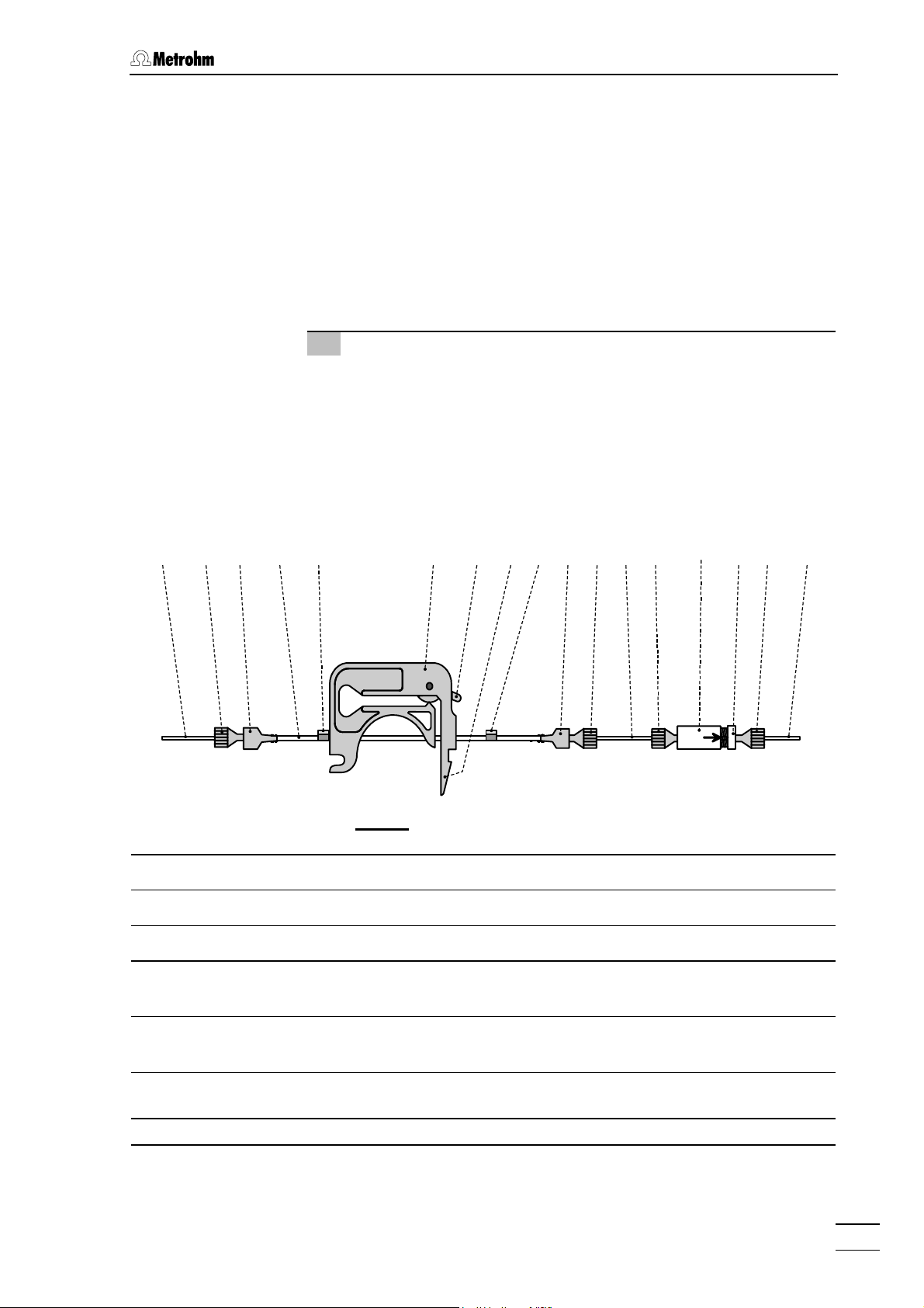
2.8 Suppressor module
• Press contact pressure lever 49 on both tubing cartridges
down as far as it will go.
• Insert the pump tubings 92 and 93 (6.1826.060) into each of
the tubing cartridges as shown in Fig. 15. The white-yellow
stopper 94 must click into the corresponding holder on the
left-hand side of the tubing cartridge.
• Place the tubing cartridges on mounting pin 53 and press
down on the right-hand side until snap-action lever 51 clicks
into position on holding clamp 50. Take care that no kinks are
formed in the pump tubing.
2 Install Filter units PEEK
• Mount a coupling 91 (6.2744.030) to the outlet end of the two
Pump tubings 92 and 93.
• Attach a piece of PTFE tubing 95 (6.1803.020) cut to the
required length (normally ca. 10 cm) using a compression
fitting 54 (6.2744.010) to the other end of this coupling.
• Attach the PTFE tubing 95 using a compression fitting 54
(6.2744.010) to the filter-screw 57 of the filter unit PEEK (see
section 2.3.6).
89/90 91 92/93 94 48 49 94 91 98/9951 5454 95 54 59 57 54
Fig. 15
Tubing cartridge 91 Coupling (6.2744.030)
48
: Installing pump tubings
49 Contact pressure lever 92 Pump tubing (6.1826.060) for H2SO4
51 Snap-action lever 93 Pump tubing (6.1826.060) for H2O
54 PEEK compression fitting
94 Stopper (white-yellow)
(6.2744.010)
57 Filter-Screw of Filter Unit
95 PTFE tubing (6.1803.020)
Part of 6.2821.120 Filter unit
59 Filter-Housing of Filter Unit
98 Suppressor inlet capillary for H2O
Part of 6.2821.120 Filter unit
89 Aspirating tubing for H2O 99 Suppressor inlet capillary for H2SO4
90 Aspirating tubing for H2SO4
761 Compact IC
39
Page 50
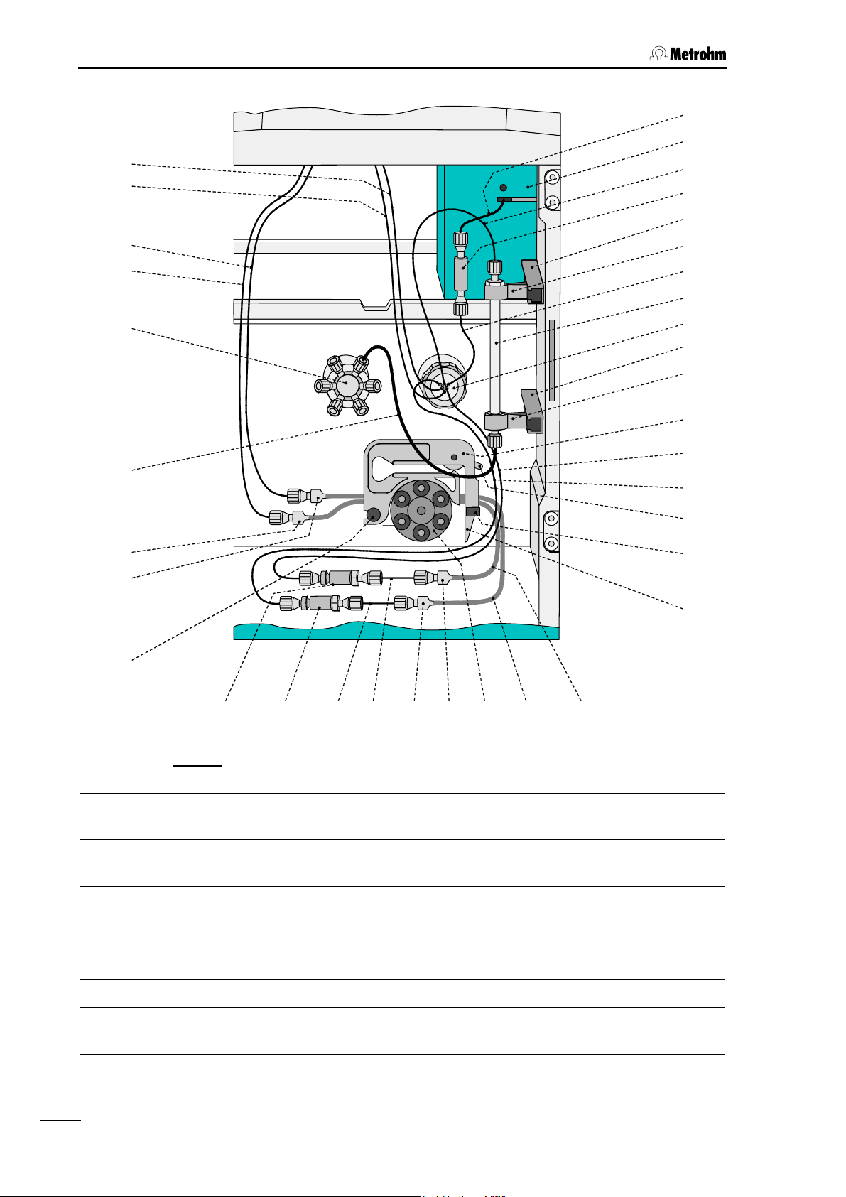
2 Installation
45
46
101
100
90
89
32
28
91
96
33
27
88
97
81
47
27
88
48
98
99
49
50
91
53
953636
95
91
91 52
Fig. 16: Connection of the separating column with suppressor
27 Mounting rail
for column holder 88
28 Column connection capillary
PEEK capillary (6.1831.010; 30 cm)
32 Injection valve 89 Aspirating tubing for H2O
33 PEEK coupling (6.2744.040) 90 Aspirating tubing for H2SO4
81 Separating column
88 Column holder (6.2027.0X0)
6.1803.020 PTFE tubing
6.1803.020 PTFE tubing
9392
51
36 Filter unit PEEK (6.2821.120) 91 Coupling (6.2744.030)
45 Inlet capillary to detector block
(fixed mounting)
46 Detector block (1.733.0110) 93 Pump tubing (6.1826.060) for H2O
761 Compact IC
40
92 Pump tubing (6.1826.060) for H2SO4
Page 51

2.8 Suppressor module
47 Suppressor module 95 PTFE tubing (6.1803.020)
48 Tubing cartridge (6.2755.000)
for pump tubings 92/93
96 Suppressor inlet capillary for
eluent
49 Contact pressure lever
97 Suppressor outlet capillary for
for adjusting the contact pressure
50 Holding clamp
98 Suppressor inlet capillary for H2O
for locking the tubing cartridge into
place
51 Snap-action lever
99 Suppressor inlet capillary for
for releasing the tubing cartridge
52 Pump drive
100 Suppressor outlet capillary for H2O
Roller head with contact rollers
53 Mounting pin
101 Suppressor outlet capillary for
for attaching the tubing cartridge
2.8.3 Connection of supply bottles
The supply lines for the regeneration and rinsing solution between the
storage bottles and the peristaltic pump are installed as follows (see
Fig. 17):
eluent
H
2SO4
H
2SO4
1 Prepare supply bottle for H2SO4
• Prepare regeneration solution suited for the desired applica-
tion and separating column (normally 20 mmol/L H
• Fill regeneration solution into supply bottle 103 (amber glass,
1 L) and label the bottle.
• Screw bottle attachment 102 on to supply bottle 103.
• Place supply bottle 103 at one of the rear positions of the
bottle rack 10 on the 761 Compact IC (see Fig. 1).
2 Connect aspirating tubing for H2SO4
• Prepare aspirating tubing 90: Cut a piece of the 6.1803.020
PTFE tubing to the required length (normally ca. 120 cm).
• Pull one end of aspirating tubing 90 through a PEEK com-
pression fitting 54 (6.2744.010) so that approx. 30 cm of the
tubing projects.
• Screw PEEK compression fitting 54 with tubing into one
opening of bottle attachment 102 attached to the regeneration solution storage bottle and tighten it so that the tubing is
firmly held.
• Insert the free end of aspirating tubing 90 into one of the
openings in 12 of the 761 Compact IC (see Fig. 2) from
above and pull it sufficiently far into the interior.
• Mount a coupling 91 (6.2744.030) to the inlet end of the rear
2SO4
).
761 Compact IC
41
Page 52
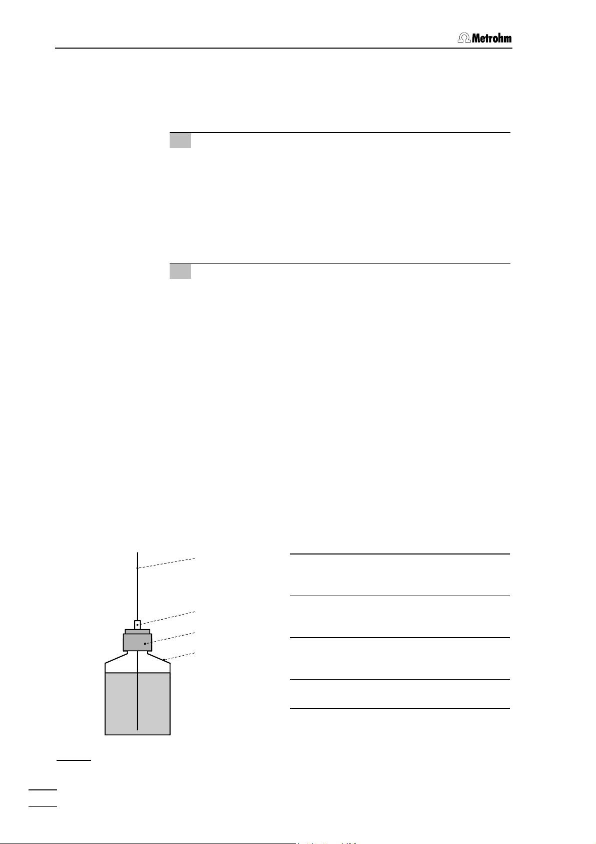
2 Installation
pump tubing 92.
• Mount a 6.2744.010 Compression fitting at the end of the
aspirating tubing 90 and screw this compression fitting on to
the coupling 91 (see Fig. 16).
3 Prepare supply bottle for H2O
• Prepare rinsing solution suited for the desired application and
separating column (normally dist. H
O).
2
• Fill rinsing solution into supply bottle 103 (amber glass, 1 L)
and label the bottle.
• Screw bottle attachment 102 on to supply bottle 103.
• Place supply bottle 103 beside the other supply bottle on the
bottle rack 10 on the 761 Compact IC (see Fig. 1).
4 Connect aspirating tubing for H2O
• Prepare aspirating tubing 89: Cut a piece of the 6.1803.020
PTFE tubing to the required length (normally ca. 120 cm).
• Pull one end of aspirating tubing 89 through a PEEK com-
pression fitting 54 (6.2744.010) so that approx. 30 cm of the
tubing projects.
• Screw PEEK compression fitting 54 with tubing into one
opening of bottle attachment 102 attached to the rinsing solution storage bottle and tighten it so that the tubing is firmly
held.
• Insert the free end of aspirating tubing 89 into one of the
openings in 12 of the 761 Compact IC (see Fig. 2) from
above and pull it sufficiently far into the interior.
• Mount a coupling 91 (6.2744.030) to the inlet end of the front
pump tubing 93.
• Mount a 6.2744.010 Compression fitting at the end of the
aspirating tubing 89 and screw this compression fitting on to
the coupling 91 (see Fig. 16).
89/90
54 PEEK compression fitting
(6.2744.010)
54
89 Aspirating tubing for H2O
6.1803.020 PTFE tubing
102
103
Fig. 17
761 Compact IC
42
: Connection of supply bottles
90 Aspirating tubing for H2SO
6.1803.020 PTFE tubing
102 Bottle attachment (6.1602.150)
103 Supply bottle (6.1608.023)
4
Page 53

2.8 Suppressor module
2.8.4 Connection of the suppressor module
The three inlets and outlets numbered 1...3 on the suppressor module
47 each have 2 permanently mounted PTFE capillaries, which must be
connected as described as follows (see Fig. 16 and Fig. 18).
1 Inlet capillary for eluent
• Screw inlet capillary 96 marked with "Eluent" of suppressor
module 47 to outlet end of separating column 81 using a
6.2744.010 Compression fitting.
2 Outlet capillary for eluent
• Screw outlet capillary 97 marked with "Detector" of suppres-
sor module 47 to coupling 33 using a 6.2744.010 Compression fitting.
• Screw inlet capillary 45 of detector block 46 to other end of
coupling 33.
H2SO4
Waste
Fig. 18
3 Inlet capillary for H2SO4
• Attach inlet capillary 99 marked with "H2SO4" of suppressor
module 47 using a 6.2744.010 Compression fitting to the filter
unit PEEK 36 connected to the rear pump tubing 92.
4 Outlet capillary for H2SO4
• Pull outlet capillary 101 marked with "Waste" of the suppres-
sor module 47 from below through one of the openings 13
out of the inner compartment of the 761 Compact IC.
• Lead outlet capillary 101 to a sufficiently large waste con-
tainer and fix it in place.
Eluent
96
Detector
H2O
101
9799
1
2
3
98
100
Waste
: Connections at suppressor module
Suppressor inlet
96
capillary for eluent
97 Suppressor outlet
capillary for eluent
98 Suppressor inlet
capillary for H
2
O
99 Suppressor inlet
capillary for H
2SO4
100 Suppressor outlet
capillary for H
2
O
101 Suppressor outlet
capillary for H
2SO4
761 Compact IC
43
Page 54

2 Installation
5 Inlet capillary for H2O
• Attach inlet capillary 98 marked with "H2O" of suppressor
module 47 using a 6.2744.010 Compression fitting to the filter
unit PEEK 36 connected to the front pump tubing 93.
6 Outlet capillary for H2O
• Pull outlet capillary 100 marked with "Waste" of the suppres-
sor module 47 from below through one of the openings 13
out of the inner compartment of the 761 Compact IC.
• Lead outlet capillary 100 to a sufficiently large waste con-
tainer and fix it in place.
7 Fasten capillaries to the side walls
• If necessary, the two aspirating tubings 89 and 90 can be
fixed in the required position in the interior with the help of a
Y.107.0150 self-adhesive strap.
• If necessary, the two outlet capillaries 100 and 101 can be
fixed in the required position in the interior with the help of a
Y.107.0150 self-adhesive strap.
761 Compact IC
44
Page 55
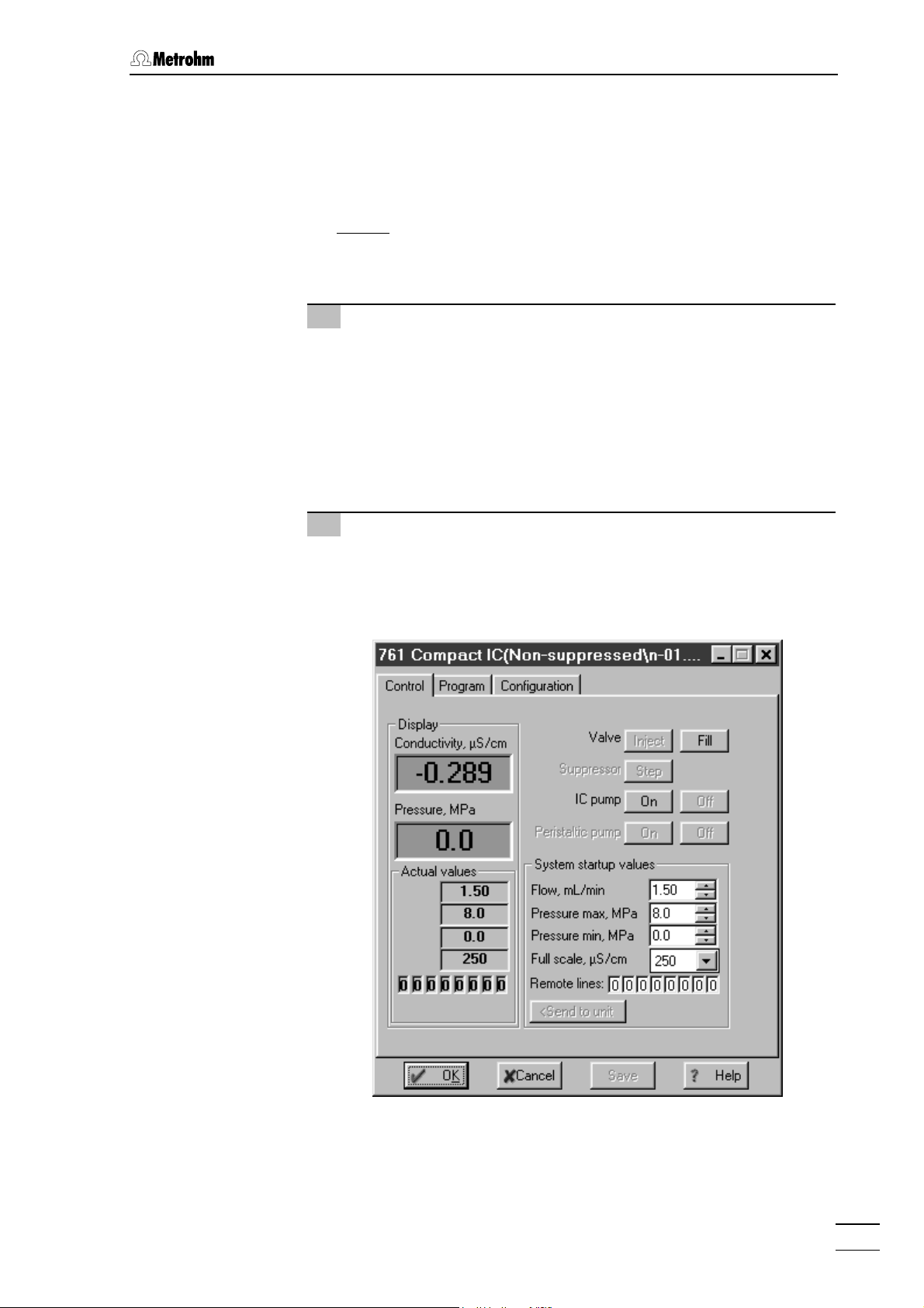
2.9 Putting into operation
2.9 Putting into operation
2.9.1 Putting into operation without suppressor
Before sample solutions can be injected at the 2.761.0010 Compact
IC (without
then conditioned with eluent until the baseline is stable. Proceed as follows:
1 Open and connect system
suppressor), the entire system must be tested for leaks and
• Start the «761 Compact IC» PC program, if it has not already
been started (see section 2.5.3).
• Select
system file suited for the inserted separating column (e.g.
01.smt
• Select the
File / Open / System in the main window. Select the
n-
) and click on <Open>.
Connect to workplace item from the Control menu of
the system window.
2 Open control window
• Double-click the 761 icon in the system window. The control
window for manual control of the 761 Compact IC appears,
which indicates conductivity, pressure and current system
parameters.
761 Compact IC
45
Page 56

2 Installation
3 Start system
• Make sure, that the aspirating tubing 63 for the high-pressure
pump is immersed in the eluent.
• Select
Startup hardware (Measure baseline) from the Control
menu in the system window. The high-pressure pump is
started, at the same time, a chromatogram window is opened
where the baseline is recorded continuously.
4 Check for leaks
• Check all capillaries and their connections between the high-
pressure pump and the detector block for escaping liquid. If
eluent escapes anywhere, the appropriate compression fitting
must be tightened further or changed.
5 Condition system
• Rinse the system with eluent until the desired stability of the
baseline is reached (normally 30…60 min; if the eluent is
changed, the establishment of the ion exchanger equilibrium
on the separating column can take longer).
• The instrument is now ready for sample determinations using
the selected system.
2.9.2 Putting into operation with suppressor
Before sample solutions can be injected at the 2.761.0020 Compact
IC (with
then conditioned with eluent until the baseline is stable. At the same
time, the suppressor module must be conditioned. Proceed as follows:
1 Open and connect system "Prep-MSM*.smt"
suppressor), the entire system must be tested for leaks and
• Start the «761 Compact IC» PC program, if it has not already
been started (see section 2.5.3).
• Select
Suppressed and select the system file Prep-MSM1.smt (for an-
ion column Dual 1) or
File / Open / System in the main window. Open the folder
Prep-MSM2.smt (for anion column Dual
2) suited for the inserted separating column. Click on
<Open>.
• Select the
Connect to workplace item from the Control menu of
the system window.
2 Open control window
• Double-click the 761 icon in the system window. The control
window for manual control of the 761 Compact IC appears,
which indicates conductivity, pressure and current system
761 Compact IC
46
Page 57

2.9 Putting into operation
parameters.
3 Start system
• Make sure, that the aspirating tubing 63 for the high-pressure
pump is immersed in the eluent.
• Select
Startup determination from the Control menu in the
system window. The high-pressure pump and the peristaltic
pump are started, at the same time, a chromatogram window
is opened where the baseline is recorded continuously. The
suppressor module is automatically switched to the next position every 20 min and conditioned in this way.
4 Set contact pressure for pump tubings
• Press contact pressure lever 49 on both tubing cartridges 48
upwards until regeneration and rinsing solution just start to be
drawn in.
• Then press contact pressure lever 49 upwards until it clicks
once more to obtain optimal contact pressure.
5 Check for leaks
• Check all capillaries and their connections between the high-
pressure pump and the detector block for escaping liquid. If
eluent escapes anywhere, the appropriate compression fitting
must be tightened further or changed.
761 Compact IC
47
Page 58

2 Installation
6 Condition system
• Rinse the system with eluent until the desired stability of the
baseline is reached (normally 30…60 min; if the eluent is
changed, the establishment of the ion exchanger equilibrium
on the separating column can take longer). After this time the
suppressor module is sufficiently conditioned too.
• The instrument is now ready for sample determinations using
the selected system.
Pump tubings are consumable material with a lifetime which depends
on the contact pressure. This is why the tubing cartridges should be
raised completely by loosening snap-action lever on the right-hand
side if the pump is to remain switched off for a considerable length of
time (the set contact pressure remains unchanged).
761 Compact IC
48
Page 59

2.10 Connection of external devices
2.10 Connection of external devices
2.10.1 Connection of the 750 Autosampler
The 750 Autosampler available from Metrohm as an option is an automatic sampler for ion chromatography. It accommodates max. 128
samples each of 730 µL, which are automatically transferred to the
sample loop attached to the injection valve of the 761 Compact IC. The
samples on the 750 Autosampler are changed by a remote signal
which is outputted by the 761 Compact IC (761 Compact IC as "Master").
In order to connect the 750 Autosampler the 6.2128.160 Cable which is
available as an option is additionally required. The 750 Autosampler is
connected to the 761 Compact IC as follows:
1 Electrical connection 761 – 750
• Connect 6.2140.010 Connector plug to contact closure strip 9
of the 750 Autosampler (see 750 Instructions for Use).
• Connect one end of the 6.2128.160 Cable to the connections
13 "EXTERNAL INJECT INPUT" and 14 "GND" on the connector plug. The two cable ends are appropriately inscribed with
"750" (white) and "GND" (brown).
• Connect the other end of the 6.2128.160 Cable to the remote
interface 24 of the 761 Compact IC (see Fig. 2).
2 Tubing connection 750 – injection valve
• Loosen rotary nipple 31 which is screwed onto the inner side
of connection 3 of the 761 Compact IC (see Fig. 3 and Fig. 4).
• Pull aspiration tubing 4 completely out from connection 3 and
screw it off from connection "1" of injection valve 32.
• Cut transfer tubing 8
shortest possible length between the needle of the 750 Autosampler and injection valve 32 of the 761 Compact IC.
• Pull the free end of transfer tubing 8
connection 3 on the 761 Compact IC and screw it onto connection "1" of injection valve 32 using a 6.2744.010 PEEK
compression fitting.
• Retighten rotary nipple on the interior side of connection 3 to
fix the transfer tubing.
3 Tubing connection injection valve – waste
• Insert 6.2744.020 Coupling (from 761 accessories) into
connection 3 of the 761 Compact IC.
• Screw aspirating tubing 4 onto the 6.2744.020 Coupling and
lead it into the waste container.
(see 750 Instructions for Use) to the
through the opening of
761 Compact IC
49
Page 60

2 Installation
4 Settings at the 750 Autosampler
• Set parameter "Run time" to 0.0 to activate the external start
of the 750 Autosampler (see section 3.5 of the 750 Instruc-
tions for Use). Filling the sample loop of the injection valve
only takes place when the impulse produced by the 761
Compact IC at remote output 3 (see point 5) makes contact
at the "EXTERNAL INJECT INPUT" of the 750 Autosampler.
The run time will then be determined externally.
5 Settings in the «761 Compact IC» program
• A time program must be drawn up for the selected system
which first switches the injection valve to the "Fill" position,
then produces an impulse at remote lead 3 to start sample
addition by the 750 Autosampler and finally switches the injection valve to the "Inject" position. The following example
shows such a program:
2.10.2 Connection of the 766 IC Sample Processor
The 766 IC Sample Processor available from Metrohm as an option is
an automatic sampler for ion chromatography. It accommodates max.
127 samples each of 2.5 mL or 11 mL, which are automatically transferred to the sample loop attached to the injection valve of the 761
Compact IC. Sample changing and filling the sample loop are started
by a remote signal produced by the 761 Compact IC (761 Compact IC
as "Master").
The 6.2141.110 Cable is required for connecting the 766 IC Sample
Processor. The 766 IC Sample Processor is connected to the 761
Compact IC as follows:
1 Electrical connection 761 – 766
• Connect the end of the 6.2141.110 Cable marked with "766"
to the remote interface 22
(see 766 Instructions for Use).
of the 766 IC Sample Processor
761 Compact IC
50
Page 61

2.10 Connection of external devices
• Connect the end of the 6.2141.110 Cable marked with "732/1"
to the remote interface 24 of the 761 Compact IC (see Fig. 2).
2 Tubing connection 766 – injection valve
• At the 761 Compact IC, loosen the rotary nipple 31 screwed
onto the interior side of connection 3 (see Fig. 3 and Fig. 4).
• Take aspirating tubing 4 completely out of connection 3 and
unscrew from connection "1" of injection valve 32.
• Cut PEEK capillary 18
installed at the 766 IC Sample Proces-
sor (see 766 Instructions for Use) to the desired length.
• Pull the free end of PEEK capillary tubing 18
through the
opening of connection 3 of the 761 Compact IC and screw it
onto connection "1" of injection valve 32 with the help of a
6.2744.010 PEEK compression fitting.
• Retighten rotary nipple 31 on the interior side of connection 3
to fix the capillary.
3 Tubing connection injection valve – waste
• Insert 6.2744.020 Coupling (from 761 accessories) into
connection 3 of the 761 Compact IC.
• Screw aspirating tubing 4 onto the 6.2744.020 Coupling and
lead it into the waste container.
4 Settings at the 766 IC Sample Processor
• For operation with the 761 Compact IC it is recommended
that the following program "761" is used with the 766 IC
Sample Processor:
parameters
method 761
number of samples: Rack
>start sequence
1 CTL:Rm: INIT
>sample sequence
1 SCN:Rm : Wait1
2 MOVE 1 : sample
3 LIFT: 1 : work mm
4 SCN:Rm : Wait1
5 PUMP 1.1 : 120 s
>final sequence
>changer settings
rack number 0
lift rate 1 12 mm/s
shift rate 20
>manual stop
CTL Rmt: **************
CTL RS232:
------------
− Method name
− Number of samples to be processed
(entire sample rack)
− Initialize remote interface
− Waiting until 761 Compact IC sends
signal on remote line 3
− Move needle to sample position
− Place lift with needle to working
position
− Waiting until 761 Compact IC sends
signal on remote line 3
− Fill sample loop with sample during
120 s
− Settings for changer functions
− Reaction to manual stop
761 Compact IC
51
Page 62

2 Installation
5 Settings in the «761 Compact IC» program
• A time program must be drawn up for the selected system
which first produces an impulse at remote lead 3 to start
sample changing on the 766 IC Sample Processor and then
switches the injection valve to the "Fill" position. A further impulse is then produced to start filling the sample loop within
120 s. At the end the injection valve is switched to the "Inject"
position, which also starts data acquisition.
6 Run conditions
In order that the joint operation of 761 – 766 functions properly
the following conditions must be fulfilled:
• The program must be started first on the 766 IC Sample
Processor, then the "Sample Queue" on 761 Compact IC.
• Remote lead 3 on the Compact IC must be set to 0 at the
start of each determination (Set
Remote line 3 = 0).
2.10.3 Connection of other devices
Any external devices can be connected to the 25-pin remote interface
24 (see Fig. 2). The 8 output lines can be used to control these external
devices.
Before an external device is connected to the remote interface 24, the
761 Compact IC must always be switched off using mains switch 19 !
The pin assignment of the remote interface, its functions and the electrical requirements and the conditions are described in section 6.1.
System startup values:
761 Compact IC
52
Page 63

3.1 Requirements
3 Operating tutorial
This section introduces you to the operation of the 761 Compact IC by
means of a brief operating tutorial which describes the basic operating steps needed for the recording of an ion chromatogram using one
of the system files supplied.
The determination of the anionic content of a drinking water sample
with the METROSEP Anion Dual 2 column with chemical suppression
is used an illustrative example. Please note that the steps and parameter settings described apply only to this example. If you use a
different separating column and system file, the procedures described
in the tutorial must be modified appropriately.
For further explanations of the operation, please refer to section 4.
3.1 Requirements
For the determination of anions in drinking water described in this tutorial, the following instruments, accessories and solutions are required:
• 2.761.0020 Compact IC
with suppressor module
• 6.1825.210 Sample loop (20 µL, PEEK)
already integrated in the 2.761.0020 Compact IC
• 6.1006.100 IC anion column METROSEP Anion Dual 2
• Eluent
2 mmol/L NaHCO
flow: 0.8 mL/min
/ 1.3 mmol/L Na2CO3 in dist. H2O
3
761 Compact IC
• Standard
Standard solution with 0.5 mg/L F
10 mg/L each of NO
–
and SO
3
–
, 5 mg/L Cl– and
2–
(in dist. H2O)
4
53
Page 64

3 Operating tutorial
3.2 Preparations
Before you start this brief tutorial, the entire IC system must be correctly
installed as described in section 2. In what follows, the most important
points for the installation are described once again (for details, see the
sections mentioned).
1 Install 761 Compact IC
⇒ Setting up instrument section 2.2
⇒ Installing and connecting detector block section 2.3.1
⇒ Mounting syringe and aspirating tubing section 2.3.2
⇒ Mounting drain tubes section 2.3.3/4
⇒ Mains connection section 2.4
⇒ Connection to PC section 2.5
2 Prepare eluent
⇒ Preparing eluent:
2 mmol/L NaHCO
/ 1.3 mmol/L Na2CO3 in dist. H2O
3
⇒ Microfiltering and degassing eluent section 5.1.3
3 Install high-pressure pump
⇒ Removing transport security screws section 2.6.1
⇒ Mounting pulsation dampener section 2.6.2
⇒ Installing eluent supply section 2.6.3
⇒ Degassing pump section 2.6.4
4 Connecting separating column and suppressor
⇒ Connecting IC anion column section 2.7.8
⇒ Connecting peristaltic pump section 2.8.2
⇒ Connecting supply bottles section 2.8.3
⇒ Connecting suppressor module section 2.8.4
⇒ Conditioning system section 2.9.2
761 Compact IC
54
Page 65

3.3 Calibration
3.3 Calibration
After the complete IC system has been installed as described in section 3.2, the first calibration can be started. A standard solution is re-
quired for this; it should contain the substances to be determined in
approximately the same concentrations in which they can be expected
in the sample.
In our example of drinking water determination using the METROSEP
Anion Dual 2 IC-anion column a 20 µL sample loop is used; this is filled
with the following standard solution:
0.5 mg/L F
5 mg/L Cl
10 mg/L NO
10 mg/L SO
(as Na+- or K+ salts in dist. water)
Please note that all program displays refer to the condition in which the
system
s-03.smt is loaded for the first time. If you want to work through
this tutorial at a later date and the system
the meantime then differences with respect to the program display and
the parameter values may occur.
–
–
–
3
2–
4
s-03.smt has been altered in
In the description of the calibration procedure it is assumed that the PC
and 761 Compact IC are not in operation and that the system must first
be conditioned again. If this is not the case (e.g. if you start the tutorial
immediately after conditioning) then you can skip steps 1 to 6.
1 Switch on 761 Compact IC
⇒ Switch on 761 Compact IC with mains switch 19 on the rear
of the instrument. After the instrument has been switched on
the mains pilot lamp 9 lights up.
2 Switch on PC
⇒ Switch on PC and start «761 Compact IC» program.
3 Open and connect system "PrepMSM2.smt"
⇒ Start PC program «761 Compact IC», if it is not already
running (see section 2.5.3).
⇒ Select
system file
<Open>.
⇒ Select
File / Open / System in the main window. Select the
PrepMSM2.smt in the folder Suppressed and click on
Connect to workplace of the Control menu in the system
window.
761 Compact IC
4 Start system "PrepMSM2.smt"
⇒ Select Start determination of the Control menu in the system
window. High-pressure pump and peristaltic pump are
started, at the same time, a chromatogram window opens
where the baseline is recorded continuously. The suppressor
55
Page 66

3 Operating tutorial
module is switched to the next position every 20 min and
conditioned in this way.
5 Condition system "PrepMSM2.smt"
⇒ Rinse IC system with eluent until the desired stability of the
baseline is achieved and the suppressor module is sufficiently conditioned (at least 1 h).
6 Stop system "PrepMSM2.smt"
⇒ Select Stop determination of the Control menu in the system
window. Data recording and time program are stopped, highpressure pump and peristaltic pump keep running on.
7 Open and connect system "s-03.smt"
⇒ Select Change of the System menu in the system window.
Select the system file
ion Dual 2 column in the folder
<Open>. The system PrepMSM2.smt is closed, the system
s-03.smt is opened and automatically connected.
s-03.smt suited for the METROSEP An-
Suppressed and click on
8 Start system "s-03.smt"
⇒ Select Start determination of the Control menu in the system
window. High-pressure pump and peristaltic pump are
started, at the same time, a chromatogram window opens
where the baseline is recorded continuously. The status bar
of this window shows the message
Measure(Baseline), beside
this running time, analysis time, absolute conductivity and
number of measuring points per second are displayed. The
messages
[Suppressed]
Running [761 Compact IC] and Waiting for INJECT
appear in the SYSTEM STATE window
⇒ Let the system run for several minutes. If the system has
already been conditioned then a stable conductivity value of
approx. 14 µS/cm will be obtained after a few minutes.
⇒ Double-click the chromatogram or select
View all of the View
menu. The sensitivity is set automatically so that all measuring points are visible.
This function is only available if the integration has been
started. In the present example the integration only starts
after a delay period
Delay = 2.6 min.
⇒ Select the desired sensitivity using the cursor keys <> or
<>. In the chromatogram window the following display is
seen, for example:
761 Compact IC
56
Page 67
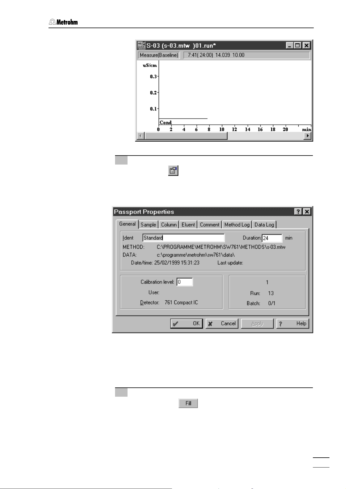
3.3 Calibration
9 Enter information for determination
⇒ Click on or select Passport of the Method menu. The
passport opens with the
General page, which contains the
general information about the determination.
761 Compact IC
⇒ Enter a title for the calibration as
⇒ Change the analysis time under
Ident (e.g. Standard).
Duration if required.
⇒ Change other parameters on the passport tabs to character-
ize sample and acquirement conditions if required.
10 Switch injection valve to "FILL" position
⇒ Click on the button of the 761 icon in the system
window to switch the injection valve to the "FILL" position. At
the same time, the suppressor module is switched to the next
position.
57
Page 68
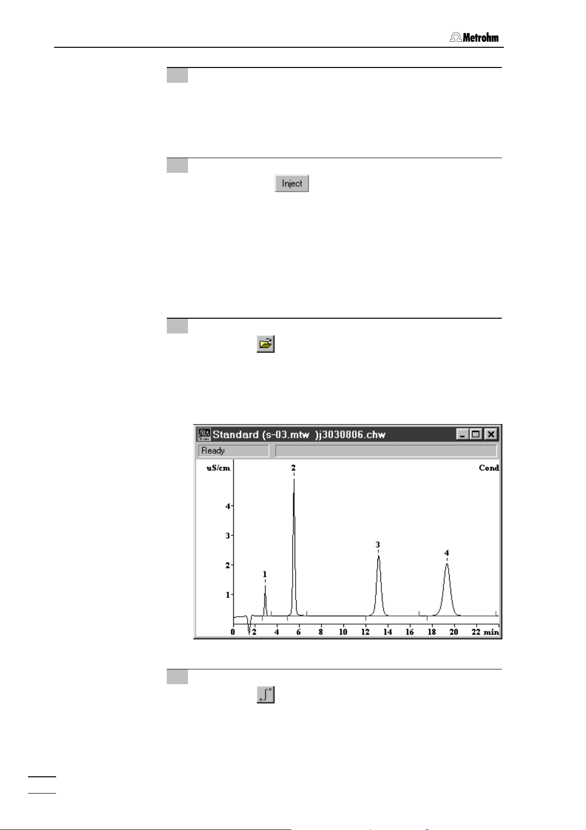
3 Operating tutorial
11 Fill sample loop
⇒ Immerse the aspirating tubing 4 attached to connection 3 in
the standard solution.
⇒ Using the syringe fixed to connection 2 siphon in ca. 1 mL
standard solution.
12 Switch injection valve to "INJECT" position
⇒ Click on the button of the 761 icon in the system
window to switch the injection valve to the "INJECT" position.
At the same time, the data recording is started automatically.
The status bar of the chromatogram window shows the mes-
Measure, the SYSTEM STATE window shows the mes-
sage
sages
Running [761 Compact IC] and INJECT done [Suppressed].
⇒ When the analysis time of 24 min set in the method has
expired the recorded chromatogram is automatically evaluated and stored. The chromatogram window then closes.
13 Open chromatogram
⇒ Click on or File / Open / Chromatogram in the main win-
dow. Select the chromatogram file
click on
<OK>. The chromatogram window is opened where
*.chw just recorded and
the found peaks are numbered and the baselines are drawn
in.
14 Modify integration parameters
⇒ Click on or select Integration from the Method menu in
the main window to open the integration parameters window.
⇒ If required (e.g. if the fluoride peak is not detected), change
the time delay
761 Compact IC
58
Delay before starting peak integration.
Page 69
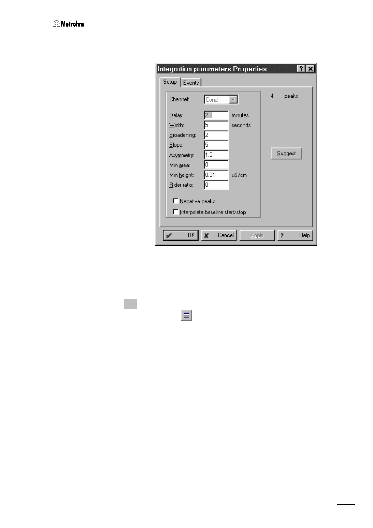
3.3 Calibration
⇒ Click on <Apply>. The Integration parameters window is
opened and the chromatogram is reintegrated.
⇒ Repeat this procedure for all other integration parameters
until the result satisfies your expectations. Click on
for each parameter change.
⇒ Close the
Integration parameters window with <OK>.
15 Modify peak allocation
⇒ Click on or select Calibration / Components from the
Method menu. The prepared table for the components fluo-
ride, chloride, nitrate, and sulfate is displayed below the
chromatogram. For all peaks which could be allocated unambiguously to a component this table contains the peak
number in the
Peak column and the retention time in the Time
column. In the chromatogram itself this retention time is indicated by the cursor (vertical line).
⇒ If the
Peak column contains a 0 the peak must be manually
allocated to a component. In this case, insert the peak number from the chromatogram into the
Time field on this row with the mouse. The corresponding
the
Peak column and click
retention time is then inserted automatically as the new time
for this component.
⇒ For each correctly allocated peak click on the retention time
Time column. This time is automatically shown in the
in the
chromatogram by the cursor. If the retention time is not located in the area of the middle of the peak then the value in
Time column should be adapted accordingly.
the
<Apply>
761 Compact IC
59
Page 70
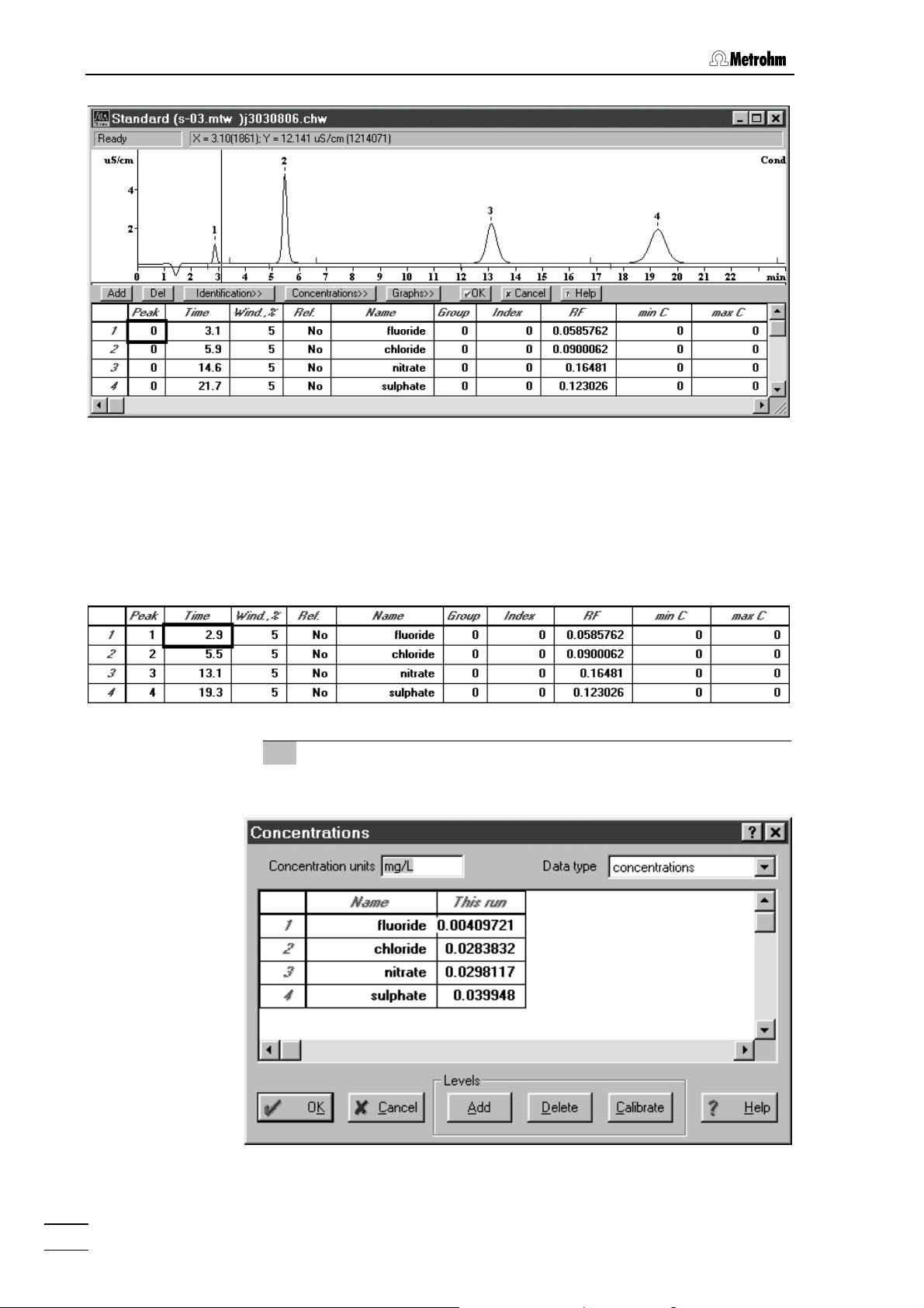
3 Operating tutorial
This is done by clicking on the chromatogram and moving
the cursor with the aid of the cursor keys <> and <> to
the middle of the peak and reading off the corresponding retention time in the status line. Enter this value (rounded off if
necessary) into the
Time column.
The optimized table could, for example, then appear as
follows:
16 Start calibration
⇒ Click the <Concentrations> button in the component window.
⇒ Click on
761 Compact IC
60
<Add>. The Add level window appears.
Page 71
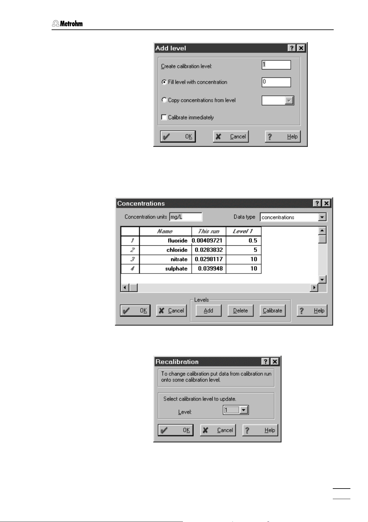
3.3 Calibration
⇒ Confirm
column
Calibration level 1 in this window with <OK>. A new
Level 1 is added in the Concentrations window.
⇒ Enter the concentrations of all components of the standard
solution used in this column:
761 Compact IC
⇒ Click on
⇒ Confirm
⇒ Click on
<Calibrate>. The following window appears:
Level 1 with <OK>.
<OK> in the Concentrations window.
61
Page 72
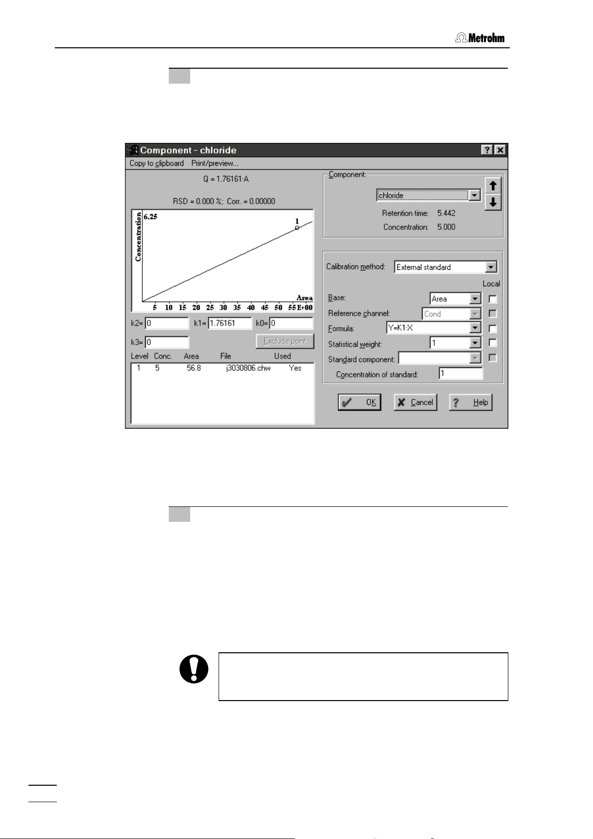
3 Operating tutorial
17 Display calibration curves
⇒ Click on <Graphs> in the Components window.
⇒ Select the desired component in the
the calibration curve should be displayed (e.g. for
Component field for which
chloride).
⇒ Close the
⇒ Close the
clicking on
Component - chloride window with <OK>.
Components window below the chromatogram by
<OK>.
18 Save chromatogram and method
⇒ Close the chromatogram window. A window appears with the
message
⇒ Click on
already exists. Overwrite?
⇒ Click on
s-03.mtw was modified. Save changes?
⇒ Click on
⇒ Save the method under the previously given name
Changes in *.chw. Modified: Calibration. Save changes?.
<Yes>. A window appears with the message *.chw
.
<Yes>. A window appears with the message Method
.
<Yes>. The File Save As window appears.
s-03.mtw.
If you want to store the method under a different name then
this must be newly selected for the system under
Setup / Processing method
.
PC icon /
761 Compact IC
62
Page 73

3.4 Sample determination
3.4 Sample determination
Following the calibration of the IC system as described in section 3.3
the first sample solution can be injected.
1 Enable "Verify sample"
⇒ Switch on the Verify sample option of the Control menu in the
system window. This causes the
dow to open at the start of each determination; the most important data for the sample can then be entered in this window.
2 Start system "s-03.smt"
⇒ Select Start determination of the Control menu in the system
window. An empty chromatogram window opens where the
baseline is recorded continuously. The messages
Compact IC]
TEM STATE
switched on the
and Initialisation [Suppressed] appear in the SYS-
window. Because of the Verify sample option
Edit sample description window is opened
automatically.
Edit sample description win-
Ready [761
3 Enter information for determination
⇒ Enter the desired information concerning the sample in the
Edit sample description window and confirm with <OK>.
761 Compact IC
4 Switch injection valve to "FILL" position
⇒ Click on the button of the 761 icon in the system
window to switch the injection valve to the "FILL" position. At
the same time, the suppressor module is switched to the next
position.
63
Page 74

3 Operating tutorial
5 Fill sample loop
⇒ Immerse the aspirating tubing 4 attached to connection 3 in
the vessel containing the drinking water sample.
⇒ Using the syringe fixed to connection 2 siphon in ca. 1 mL
drinking water.
6 Switch injection valve to "INJECT" position
⇒ Click on the button of the 761 icon in the system
window to switch the injection valve to the "INJECT" position.
At the same time, the data recording is started automatically.
The status bar of the chromatogram window shows the mes-
Measure, the SYSTEM STATE window shows the mes-
sage
sages
Running [761 Compact IC] and INJECT done [Suppressed].
⇒ When the analysis time of 24 min set in the method has
expired data recording is automatically stopped and the
chromatogram is integrated and evaluated. In the chromatogram window the peaks which have been found are numbered and the baseline drawn. In the
the message
Finished [Suppressed] appears. It is now possible
SYSTEM STATE window
to record further samples with the same system.
⇒ At the end of the determination, the chromatogram window is
closed and the chromatogram is saved automatically. The file
name is generated automatically and contains date and time
in a coded form:
st
numeral: Alphabetical code for year
1
(e.g. j = 1999, k = 2000, l = 2001, etc.)
nd
2
numeral: Code for month
(1...9 = Jan....Sept., a...c = Oct....Dec.)
rd+4th
3
5
numeral: Day (01 ... 31)
th
- 8th numeral: Time (hh:mm)
761 Compact IC
64
Page 75
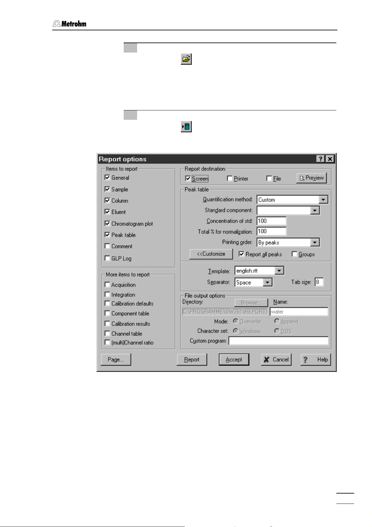
3.4 Sample determination
7 Open chromatogram
⇒ Click on or File / Open / Chromatogram in the main win-
dow. Select the chromatogram file
click on
<OK>. The chromatogram window is opened where
*.chw just recorded and
the found peaks are numbered and the baselines are drawn
in.
8 Report output
⇒ Click on or select Make report of the Process menu in the
main window. The
Report Options window appears.
761 Compact IC
⇒ Under
Report destination, switch on the desired target option
for report output.
⇒ Under
Items to report and More items to report, click all desired
elements for the report output.
⇒ Click on <Report> to start the report output to the selected
target.
65
Page 76

3 Operating tutorial
9 Print report
⇒ Click on or select Print of the File menu in the main
window. The standard printing window is opened where
printer, printing range and number of copies can be selected.
After confirmation with
<OK> the results including the chro-
matogram are printed out.
761 Compact IC
66
Page 77

4.1 Fundamentals of the operation
4 Operation
This section describes the most important points concerning the
operation of the 761 Compact IC. For further details please refer to the
on-line help in the PC program which can provide you with the
required information rapidly and conveniently from any place in the
program.
4.1 Fundamentals of the operation
4.1.1 Starting/closing the program
Start the «761 Compact IC» program
Start the program
Double-click this icon or the
Compact IC 1.1» program. The Login window appears:
Enter your password and click on
After software installation, the program can be
started without entering a
tion of users, see section 4.2.2.
Metro761.exe file to start the «761
<Log In>.
Password. For the defini-
761 Compact IC
Close the «761 Compact IC» program
761 COMPACT IC / File / Exit
Exit the «761 Compact IC» program.
The program is also quit by clicking on
of the main window
761 COMPACT IC.
in the upper right part
67
Page 78

4 Operation
4.1.2 Glossary
System
The term “system“ is used to describe the combination of instrument
settings, time program and process method which have been opti-
mized for the specific separating column and the determination to be
carried out with it. A system is used to start single determinations or determinations with the help of a sample queue.
Systems are stored as system files (
*.smt) in the Systems directory.
Method
A method contains all information necessary for data acquisition, integration, peak evaluation and quantification. It can be considered
as the chromatogram template, i.e. chromatogram without raw data.
Methods are stored as method files (
*.mtw) in the Methods directory.
Each system is linked to a method. This method is called processing
method and is opened automatically at the start of a new determina-
tion.
Chromatogram
A chromatogram is a graphic plot of the elution curve (signal vs. time)
recorded following a chromatographic separation on a separating column.
Chromatograms are stored as chromatogram files (
*.chw) in the Data
directory. As well as the measuring data the chromatogram files also
contain the method parameters and system settings which have been
used for data recording, data processing and remote control.
Determination
In order to carry out a determination a suitable system must be selected for the separating problem. The result of the determination is a
chromatogram, in which the measuring data and results of the determination are stored.
Calibration
Calibration is used to describe the method of determining the relationship between the peak height or peak area found for one component
and its concentration in the sample. The result of the calibration is a
calibration function (calibration curve), which shows the relationship
between the amount of sample and the evaluated quantity.
The determination of the calibration function with reference solutions
can be carried out as a one-point or as a multiple-point calibration.
The calibration method which is mainly used in ion chromatography is
the external standard calibration (absolute calibration); calibration
with an internal standard (relative calibration) or tabulated calibra-
tion are also possible.
761 Compact IC
68
Page 79

4.1 Fundamentals of the operation
Integration
Integration is to be understood as being the method for determining the
peak area and peak height with the aid of approximate baselines. The
integration algorithm included in the program is influenced by the inte-
gration parameters and the optionally programmable integration
events which are defined in the method. In addition, the integration can
be manually corrected later with the aid of the peak editor.
Sample queue
A sample queue is used for the automated processing of series of
samples, particularly in combination with a sample changer.
Batch reprocessing
Batch reprocessing is understood to be the subsequent reprocessing
of a series of chromatograms which have been loaded in a batch reprocessing queue. During reprocessing with a selected method the settings for calibration, integration, passport, appearance and report can
be altered at will.
4.1.3 Overview of program windows
The «761 Compact IC» program consists of different windows whose
functionality is linked together. The different windows are:
761 COMPACT IC Main program window for file administration,
printing, opening of systems, methods and
chromatograms, login and user rights, optional
settings and window handling.
CHROMATOGRAM Window for graphic plot of running or recorded
chromatograms.
SYSTEM Window for loaded system with possibility for
manual control of the 761 Compact IC.
761 Compact IC
SYSTEM STATE Window for display of status messages for the
connected system.
WATCH WINDOW
QUEUE EDITOR Window for edition of sample queues and batch
Window for display of conductivity and pressure.
reprocessing queues.
69
Page 80
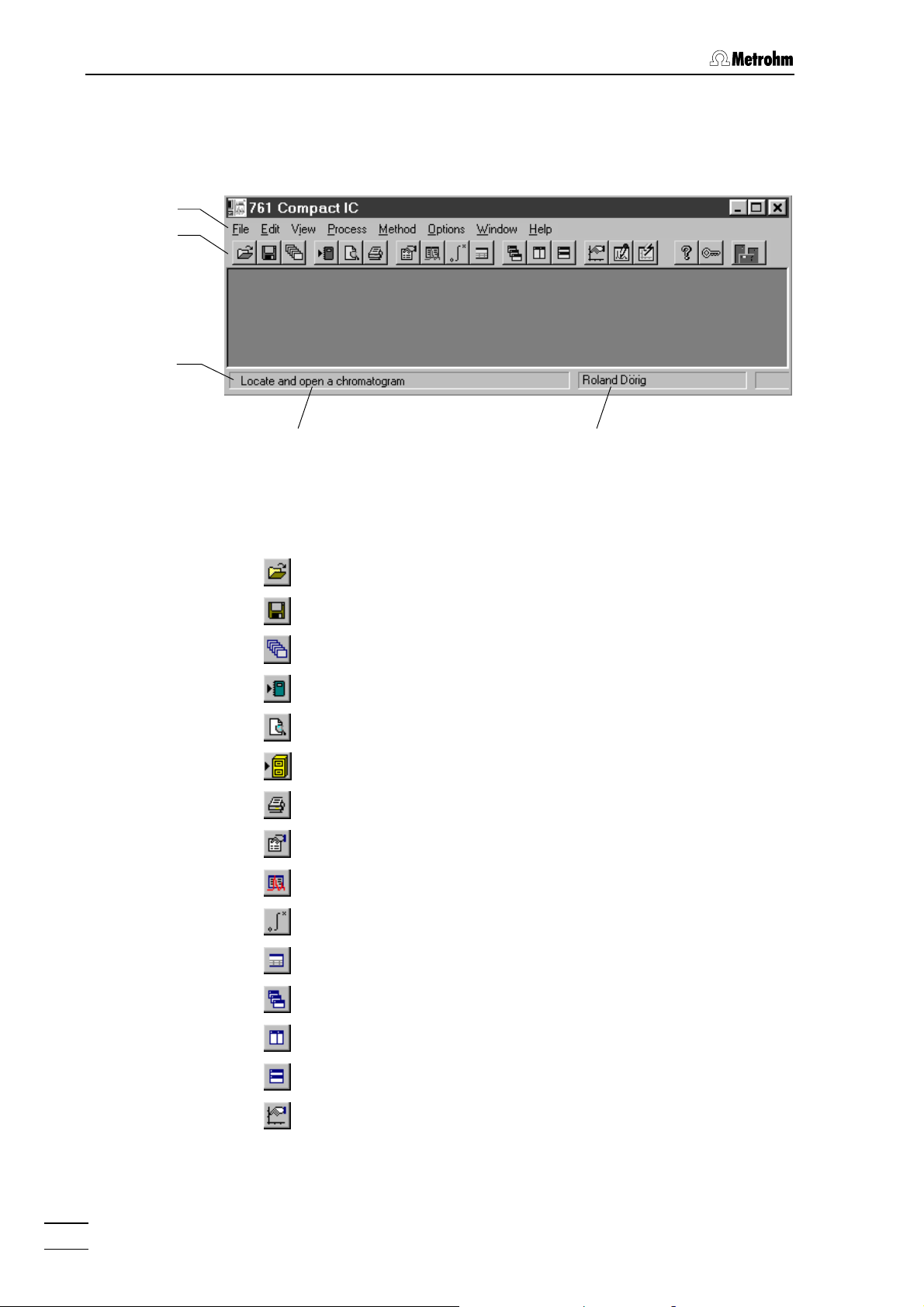
4 Operation
4.1.4 Main window elements
The elements of the main window 761 COMPACT IC are the menu bar,
the tool bar and the status bar, indicating prompts and logged-in user.
Menu bar
Tool bar
Status bar
4.1.5 Icons of the main window
The following icons are displayed in the 761 COMPACT IC main window:
Open chromatogram
Save chromatogram
Open last batch reprocessing file
Report settings
Print preview
Send chromatograms to «Autodatabase»
Print report
Passport
Logged-in user
Prompts, information
General method settings
Integration parameters
Component table
Cascade all opened chromatogram windows
Vertical tiling of open chromatogram windows
Horizontal tiling of open chromatogram windows
Appearance of the chromatogram window
761 Compact IC
70
Page 81

4.1 Fundamentals of the operation
Enable/disable peak editor mode
View whole chromatogram
Help
Lock system
Connected system
4.1.6 Overview of file types
The following file types are produced by the «761 Compact IC» software:
*.bar Batch reprocessing file
This binary file contains data of the batch reprocessing
queue. The
folder.
*.bar file is stored automatically in the Data
*.cal Calibration file
This binary file contains calibration data, which can be exported with
calibration
folder.
ods
*.chw Chromatogram file
761 COMPACT IC / Method / Calibration / Export
. The *.cal file is stored automatically in the Meth-
This binary file contains chromatogram, system and
method data of a determination. The
automatically in the
*.mtw Method
This binary file contains the data acquisition method, which
can be linked to a system. The
cally in the
*.que Sample queue file
Methods folder.
This binary file contains sample table queue. The
is stored automatically in the
*.rtt Report template
This ASCII file contains a report template. The
stored in the program folder.
*.chw file is stored
Data folder.
*.mtw file is stored automati-
*.que file
Methods folder.
*.rtt file is
761 Compact IC
*.smt System file
This ASCII file contains the system settings. The
stored automatically in the
*.dev Device file
This ASCII file contains drivers for devices. The
stored in the
*.stm file is
Systems folder.
*.dev file is
Devices folder.
71
Page 82

4 Operation
4.1.7 Context sensitive menus
Some of the menu functions of the program windows are also accessible by clicking on the desired window or item and pressing the right
mouse button. The pop up windows have different contents and functions depending on the selected active window or item type.
4.1.8 Keyboard and mouse functions
The mouse can be used to carry out the normal program operating
functions such as the selection of menu items and fields. It can additionally be used for magnifying a section of a chromatogram (zoom-
ing). To zoom a portion of the plot it is necessary to place the mouse
cursor to the upper left corner of the square to zoom, press the left
mouse button and drag the cursor to the lower right corner of the rectangle. After releasing of the left mouse button the selected region will
be zoomed full-screen. If the cursor is active in the peak editor mode
then it can be moved by pressing down the right-hand mouse key.
The keyboard can also be used to scale a chromatogram in the window, as described below.
Keyboard quick reference
Cursor is inactive:
[ up ] Increases sensitivity on the Y axis.
[ down ] Reduces sensitivity on the Y axis.
[ right ] Expands a chromatogram on the X axis.
[ left ] Shrinks a chromatogram on the X axis.
[ Ctrl ] + [ Home ] Autoscale procedure on the X axis (shows all
on X).
[ Ctrl ] + [ End ] Autoscale procedure on the Y axis (shows all
on Y).
1
[ PageUp ] Shifts a chromatogram on
/10 part of a screen
upwards.
1
[ PageDown ] Shifts a chromatogram on
/10 part of a screen
downwards.
[ Shift ] + [ up ] Increases a distance between channels of a
chromatogram.
[ Shift ] + [ down ] Reduces a distance between channels of a
chromatogram.
[ 0 (Zero) ] Adjusts a zero on the last point of a chroma-
togram (running chromatogram) or its lowest
level (finished run).
Only part of the chromatogram is on screen:
761 Compact IC
72
Page 83

4.1 Fundamentals of the operation
[ Ctrl ] + [ right ] Moves one window right (without change of
scale on X and Y axes).
[ Ctrl ] + [ left ] Moves one window left (without change of
scale on X and Y axes).
[ Home ] Shows the beginning of a chromatogram (with-
out change of scale on X and Y).
[ End ] Shows the end of a chromatogram (without
change of scale on X and Y).
[ 0 (Zero) ] Adjusts a zero on the lowest level in the win-
dow.
Cursor is active:
[ 0 (Zero) ] Adjust a zero in site of the cursor.
[ right ] Moves cursor left to right.
[ Shift ] + [ right ] Quickly moves cursor left to right.
4.1.9 Help
[ left ] Moves cursor to the left.
[ Shift ] + [ left ] Quickly moves cursor to the left.
[ Home ] Moves cursor to beginning of a window.
[ End ] Moves the cursor to end of a window.
[ Shift ] + [ End ] Sets the beginning of a window in site of the
cursor.
[ Shift ] + [ Home ] Sets the end of a window in site of the cursor.
By clicking on , by clicking on , by selecting the Help /
Contents menu item, or by pressing the [ F1 ] key you can get on-line
help on the current topic anywhere in the program.
Green texts can be clicked to jump to a different Help topic.
761 Compact IC
Violet texts identify the dialog item, parameter or button in
the corresponding window.
Blue texts identify important information.
73
Page 84

4 Operation
4.2 Instrument and software settings
4.2.1 Fonts
761 COMPACT IC / Options / Fonts
This option allows the selection of fonts used by the system.
Font for dialog... Selection of font used for dialog boxes.
Default setting:
Font for reports... Selection of font used for report output to the
screen or printer.
Default setting:
Font for tables... Selection of font used for data presentation in
tables on the screen.
Default setting:
Font for plots... Selection of font used for labels on chroma-
togram plots and calibration curves.
Default setting:
MS Sans Serif / Standard / 8 pt.
Courier New / Standard / 10 pt.
MS Sans Serif / Bold / 8 pt.
Times New Roman / Bold / 10 pt.
Save fonts configuration Save chosen font configuration.
4.2.2 Security system
The «761 Compact IC» program has a security system based on the list
of users. Every user has his unique password and one of the following
access levels:
Novice Restricted access to program functions. Allows
Master Access to all program functions with few excep-
Administrator Access to all program functions.
It is recommended to make user lists and enter passwords as a first action after system installation. So, select the menu item
Options / Security
tering a password. The
only start and stop of determinations using existing system and method files and manual
control of the 761 Compact IC. Modifications of
system, method and data files are not allowed.
tions: the user cannot set
Hardware settings and security system.
Global preferences,
761 COMPACT IC /
and click on <Log In> in the Log In window without en-
Security options window appears:
761 Compact IC
74
Page 85
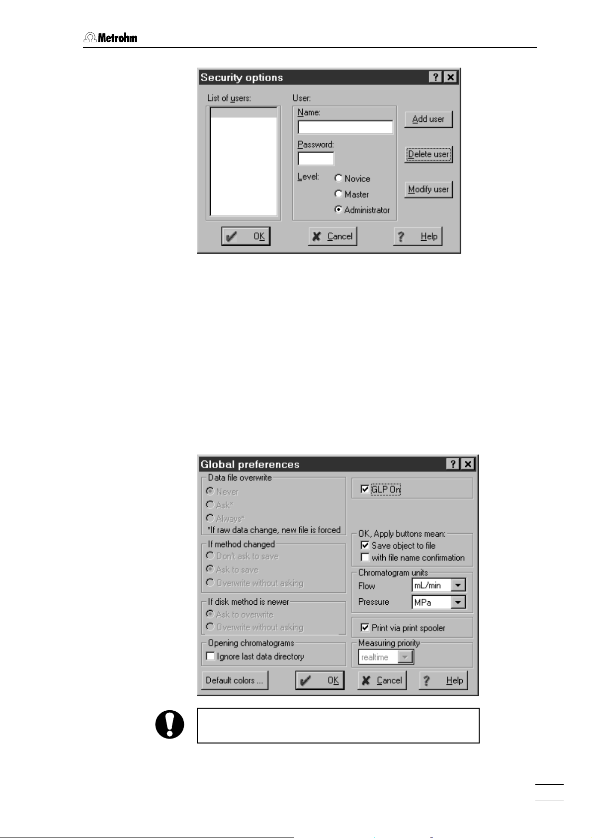
4.2 Instrument and software settings
Enter user name, password and access level for all users. Don't forget
to make one of the user an
open again. At the end, click on
Administrator, otherwise this window will not
<OK>.
After configuration of the security system the program prompts for the
password every time the system starts. This user name stamps all
methods, chromatograms and reports. It is possible at any time to
change the user with the menu item
.
tem
4.2.3 Global settings
761 COMPACT IC / Options / Global preferences
This window is used for global program settings.
761 COMPACT IC / Options / Lock sys-
761 Compact IC
This window is only accessible for users with
access level.
GLP On If this option is enabled, the following parame-
Administrator
ters are automatically set:
75
Page 86

4 Operation
Data file overwrite = Never
If method changed = Don't ask to
save
If disk method is newer = Ask to overwrite
Data file overwrite Overwriting of chromatogram files:
Never Chromatogram files cannot be overwritten. A
modified chromatogram is saved as a new file
with the file name number raised by 1.
Ask The user is asked if the chromatogram should
be overwritten.
Always Chromatogram files are always overwritten
without confirmation.
If method changed Saving of method files:
Don't ask to save The method file is not saved automatically. It
can be saved only with
File / Save / Method.
Ask to save The user is asked if the method should be
saved.
Overwrite without asking
Method files are overwritten without confirmation.
If disk method is newer Overwriting of method files:
Ask to overwrite The user is asked if the method should be
overwritten.
Overwrite without asking
Method files are overwritten without confirmation.
Opening chromatograms Opening of chromatograms:
Ignore last data directory
If this option is enabled, the default data direc-
Data is opened.
tory
OK, Apply buttons mean
Save object to file If this option is enabled, the <Apply> button in
system settings windows is replaced by the
<Save> button. The system settings are saved
<Save> or <OK> button is clicked.
if the
with file name confirmation
If this option is enabled, the
<Apply> button in
system settings windows is replaced by the
<Save as> button. The system settings can be
saved in a new file if the
<Save as> or <OK>
button is clicked.
761 Compact IC
76
Page 87

4.2 Instrument and software settings
Chromatogram units Units for chromatograms:
Flow Unit for flow rate: µL/min, mL/min
Pressure Unit for pressure: MPa, psi, bar, atm
Print via print spooler
Measuring priority Setting the priority of program execution. real-
<Default colors> Default colors for chromatographic windows
4.2.4 COM port
761 COMPACT IC / Options / 761 Compact IC:COM1
This menu item opens the Links window for COM port (serial RS232 interface) selection and settings.
Switch on/off printing via print spooler. Switch
off this option if you use a GDI printer.
time means that the «761 Compact IC» program
has the highest priority,
normal means that all
active programs have the same priority.
(details see section 4.5.3).
If
COM1 is clicked with the right mouse button, the following menu items
appear:
Put on desktop Possibility for setting COM port parameters for
recording data transfer (details see on-line
help).
Change Possibility for changing the COM port (default
setting:
COM1). The following window is
opened, where the interface can be changed
by clicking on the desired COM port.
761 Compact IC
77
Page 88

4 Operation
4.3 Systems
The term “System“ describes the combination of instrument settings,
time program and process method which has been optimized for a
specific separating column and the determination to be carried out with
it. A system is used to start single determinations or determinations with
the help of a sample queue. Systems are stored as system files (
Systems directory.
in the
4.3.1 System window
A system window is opened with 761 COMPACT IC / File / Open / System
and the selection of the desired system file. It contains icons for PC,
Watch window (screen) and 761 Compact IC.
*.smt)
Watch window
PC
4.3.2 System file handling
The following menu items are used for opening, changing, saving and
closing of systems:
761 COMPACT IC / File / Open / System
Load an existing system file (*.smt) from the Systems directory and open
the corresponding
The directory and name of the opened system file are displayed in the
title bar of the
cates that the system settings have been changed since the last saving.
SYSTEM / System / Open other
Load an existing system file (*.smt) from the Systems directory and open
a new
SYSTEM window. The system parameters can be changed for this
system, but it can not be connected without disconnecting the actual
system first.
SYSTEM window. A star ( * ) at the end of the name indi-
761 Compact IC
SYSTEM window
SYSTEM / System / Change
Disconnect the current system, open the selected new system and
connect it automatically.
761 Compact IC
78
Page 89

4.3 Systems
SYSTEM / System / Save
Save the current system settings in a system file (*.smt) in the Systems
directory.
SYSTEM / System / Close
Disconnect the selected system (if it is connected) and close the system window.
4.3.3 System functions
Connect and disconnect system
To make possible manual control of the instrument and start of determinations the selected system must be connected to the PC. Only one
system can be connected at the same time. Systems are connected
and disconnected as follows:
SYSTEM / Control / Connect to workplace
Connect selected system to the COM port of the PC. If the system is
connected, the two buttons
<Inject> and <Fill> appear on the 761 icon
in the system window for manual control of the injection valve (see section 4.3.7).
At the same time, the
clicked, the
SYSTEM window is always displayed in front of all other win-
icon appears on the tool bar. If this icon is
dows.
SYSTEM / Control / Disconnect from workplace
Disconnect selected system from the COM port of the PC. If the system
is disconnected, the two buttons
<Inject> and <Fill> disappear on the
761 icon in the system window. Manual control is not available for this
system any more, but all other system settings can be modified and
saved.
Start/stop hardware and record baseline
SYSTEM / Control / Startup hardware (Measure Baseline)
Starting the hardware at the 761 Compact IC includes sending of
tem startup values
, starting of the high-pressure pump and (if present)
starting of the peristaltic pump.
Sys-
761 Compact IC
At the same time, the recording of the measurement signal using the
method of the connected system is started. Independently of the set
chromatogram
data acquisition is stopped with
Duration, the measurement signal is recorded until the
SYSTEM / Control / Stop data acquisition or
a new determination is started. Alternatively the baseline recording can
be stopped by clicking the
icon of the chromatogram window. In
this case the user is asked if the recorded baseline should be saved or
not.
79
Page 90

4 Operation
SYSTEM / Control / Shutdown hardware
High-pressure pump and (if present) peristaltic pump at the 761 Compact IC are immediately stopped. A running determination and an active sample queue are also stopped and the remote output lines are set
to the values defined under
SYSTEM / Control / Stop data acquisition
Hardware / Remote lines after power on.
Stop recording of the baseline.
Start/stop determinations
SYSTEM / Control / Start determination
Start determination using the settings of the selected system. At this
start command, the
System startup values are set at the 761 Compact IC.
The high-pressure pump and the peristaltic pump are started if they are
not already running. The time program and the data recording are
started either immediately (
injection valve to the "Inject" position (
window.
mode
Start with determination) or after switching the
Start with inject) as set in the Start
SYSTEM / Control / Stop determination
Stop running determination. Data acquisition and time program are
terminated immediately. The recorded chromatogram is saved automatically if the
Processing
Save chromatogram after the run option on the Passport /
tab is enabled.
Alternatively the determination can be stopped by clicking the
of the chromatogram window. In this case the user is asked always if
the determination should be saved or not.
SYSTEM / Control / Stop data acquisition
Stop data acquisition of the running determination immediately and
save the recorded chromatogram automatically if the
after the run
option on the Passport / Processing tab is enabled. The time
Save chromatogram
program of the running determination is continued normally.
Options for determinations
SYSTEM / Control / Auto restart
If this option is enabled, a new determination is started automatically
using the current system after the preceding determination has been
finished normally or stopped manually.
icon
The
Auto restart option is disabled if determinations are made with an
active sample queue.
SYSTEM / Control / Verify sample
If this option is enabled, the Edit sample description window is opened
automatically at the start of each determination for entry of the following
sample information:
761 Compact IC
80
Page 91
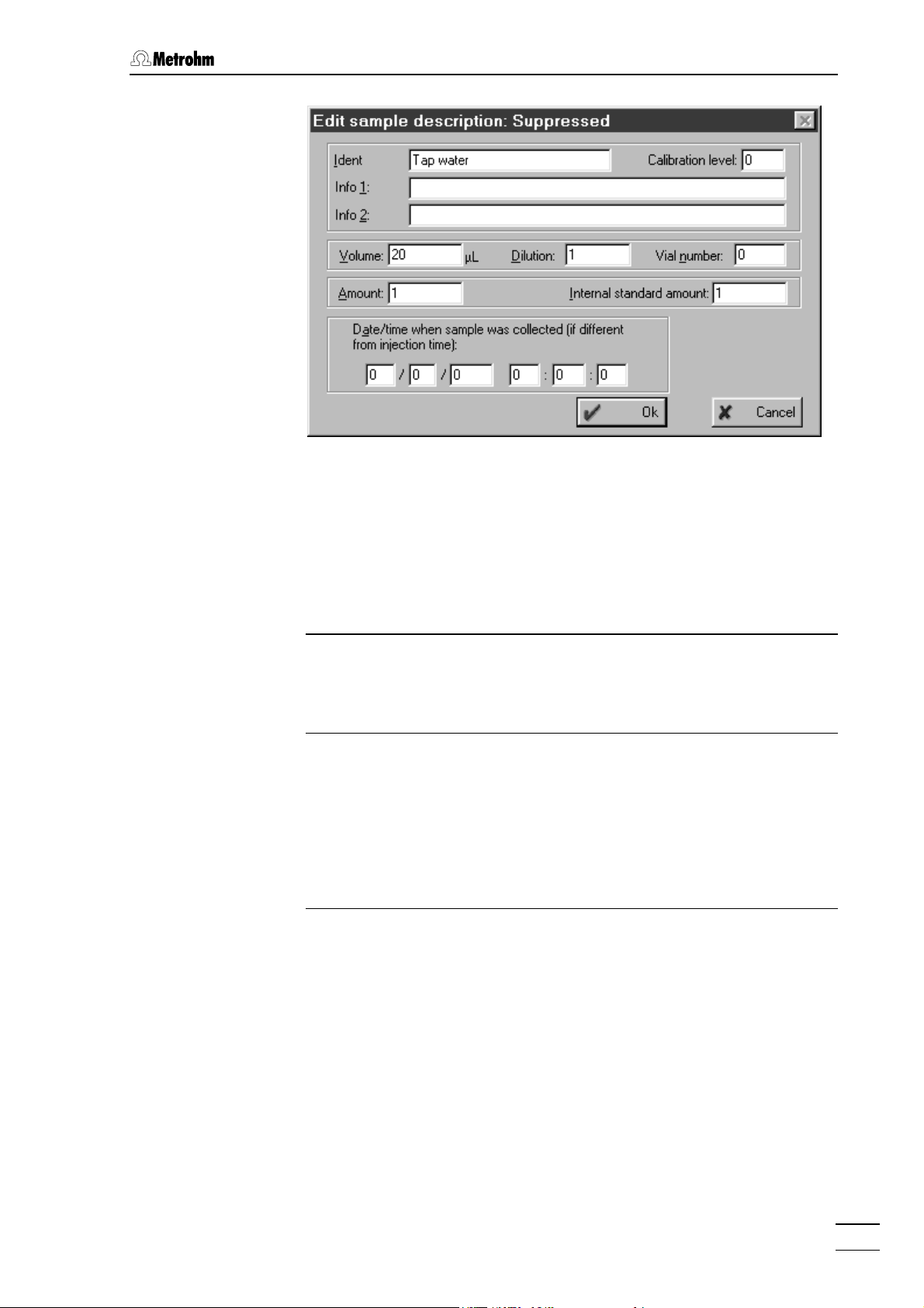
4.3 Systems
Ident User defined identifier (title) for the chroma-
togram to be displayed in the title bar of the
chromatogram window and in the
open window.
Chromatogram
Calibration level Calibration level (0 = sample; 1…n = calibra-
tion solutions).
Info 1 / Info 2 Sample description.
Volume Injected volume in µL.
Dilution Dilution of the sample.
Vial number Autosampler vial position to take sample from.
Amount Sample amount. If this value is different for the
calibration run (c) and the sample run (s), the
component concentrations of the sample are
calculated as follows:
C
Internal standard amount Concentration of the internal standard compo-
= Cc • Amounts / Amountc
s
nent for relative concentration calculations.
Date/time when... Date and time of sample collection (the default
values are equal to the date and time when the
chromatogram starts).
Verify sample option is disabled if determinations are made with an
The
active sample queue.
761 Compact IC
81
Page 92

4 Operation
4.3.4 System settings
Modify system window
SYSTEM / Setup / Drag icons
If this option is enabled, the system icons can be resized and moved in
the
SYSTEM window and the SYSTEM window itself can be resized.
To resize an icon or the window, move the cursor to the desired object
until
the desired size.
appears. Press the left mouse button and resize the object to
To move an icon, move the cursor to the desired object until
pears. Press the left mouse button and move the object to the desired
place.
Watch window display
SYSTEM / Setup / Watch window
If this option is enabled, the
WATCH WINDOW with conductivity and
pressure display is automatically opened if a determination or measure
baseline is started (see section 4.3.6).
Set start mode
SYSTEM / Setup / Start mode
This menu item opens the
Start mode window for definition of start mode
for time program and data acquisition.
ap-
This window contains the following two fields:
Start with determination The loaded object is started at the moment the
determination is started.
Start with inject The loaded object is started at the moment the
sample is injected.
The two objects available are:
RECORDER Data acquisition defined in the method.
761 Compact IC Time program defined on the Program tab of
the system control window.
These two objects can be moved from one field to the other using the
or buttons.
761 Compact IC
82
Page 93

4.3 Systems
Print system parameters
SYSTEM / Setup / Parameters / Print
A report of the system parameters including the time program is created and opened using the «Wordpad» program. The
*.txt file opened
can be printed, saved and exported into other programs. The system
report includes the name of the method linked to the system, the configuration settings for the 761 Compact IC, the system startup values
and the time program (incl.
ists and is switched on (
Remote configuration), if such a program ex-
ENABLED).
4.3.5 PC icon
Menu options for PC icon
The PC icon is one of the three components of the
SYSTEM window. If
the system is connected and this icon is clicked with the right mouse
button, the following menu appears:
Open Load the processing method linked to the system
and open an empty chromatogram window.
Setup Open PC setup window for selection of processing
method and data source.
Select processing method and data source
The
PC / Setup menu item opens the following window:
761 Compact IC
This window contains the following two fields:
Processing method Directory and name of the method file (*.mtw)
linked to the system.
The method file can be selected with
and opened with
<show>.
<choose>
83
Page 94
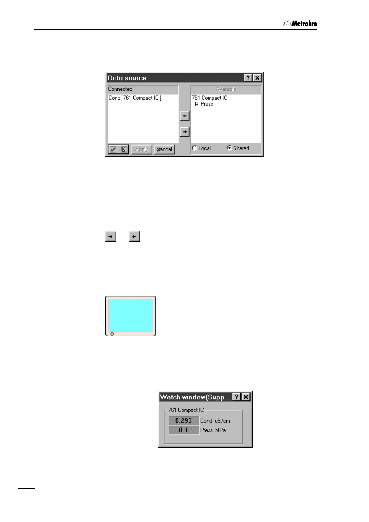
4 Operation
Connected data source Data source for main measurement channel. By
clicking on
<choose>, the Data source window is
opened for selection of the data source:
This window contains the following two fields:
Connected Connected data source.
Default setting:
Available Available data sources of the 761 Compact IC:
# Cond Conductivity
# Press Pressure
Cond[ 761 Compact IC]
The data sources can be moved from one field to the other using the
or buttons (only one data source can be connected).
4.3.6 Watch window
Menu options for screen icon
The watch window icon is one of the three components of the
window. If the system is connected and this icon is clicked with the right
mouse button, the following menu item appears:
Open Open the WATCH WINDOW for live display of conduc-
SYSTEM
tivity and pressure:
The colors of the watch window fields can be
changed by clicking the fields with the right mouse
button and selecting the menu item
761 Compact IC
84
Choose color / ... .
Page 95

4.3 Systems
4.3.7 Instrument icon
Menu options for instrument icon
System
disconnected
System connected
Injection valve in
"INJECT" position
System connected
Injection valve in
"FILL" position
The instrument icon for the 761 Compact IC is one of the three components of the
SYSTEM window. If the system is connected, the 761 icon
contains two buttons for manual control of the injection valve:
<Inject> Switch injection valve to "INJECT" position.
<Fill> Switch injection valve to "FILL" position.
If the system is connected and the 761 icon is clicked with the right
mouse button, the following menu appears:
Open Open the system settings window.
Hardware Open the hardware settings window.
Diagnostics Open the diagnostics window.
System parameters for disconnected system
A double-click on the instrument icon or selection of the
item using the right mouse button opens the system settings window.
For a disconnected system, the
Initial tab is displayed.
Open menu
761 Compact IC
85
Page 96
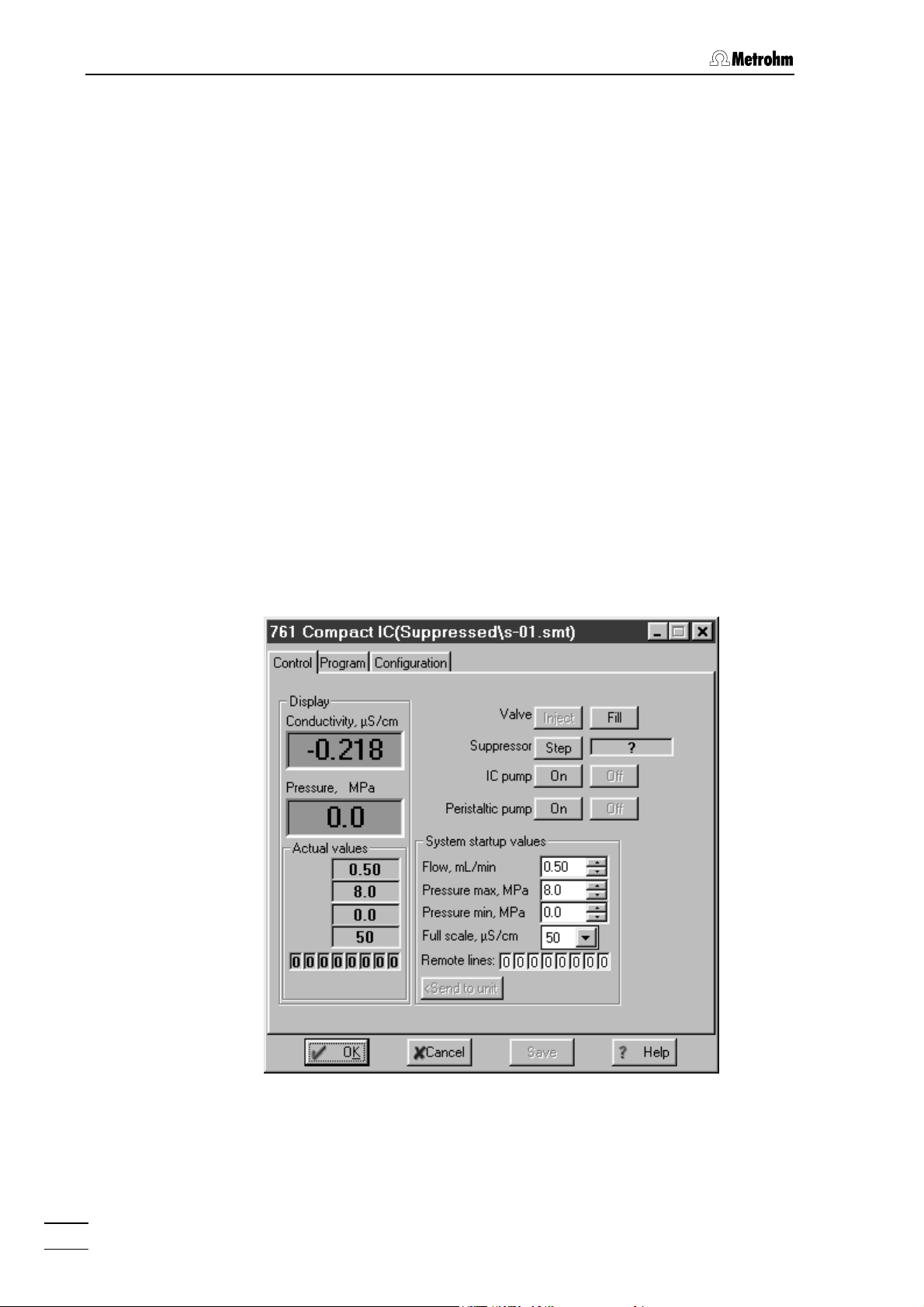
4 Operation
Flow, mL/min Startup value for flow rate of the high-pressure
pump.
Entry range:
Pressure max, MPa Startup value for maximum pressure limit for
0.20 ... 2.50 mL/min
high-pressure pump.
Entry range:
Pressure min, MPa Startup value for minimum pressure limit for
0.0 ... 25.0 MPa
high-pressure pump.
Entry range:
Full scale, µS/cm
Startup value for full scale range.
Selection:
Remote lines Startup value for remote line settings 1…8.
Selection:
0.0 ... 25.0 MPa
50, 250, 1000 µS/cm
0, 1
Instrument control for connected system
A double-click on the instrument icon or selection of the
Open menu
item using the right mouse button opens the system settings window.
For a connected system, the
Control tab is displayed. It allows manual
control of the 761 Compact IC functions and setting of startup values to
be sent to the instrument. This tab shows the current measurement values for conductivity and pressure.
Conductivity, µS/cm Live display of measured conductivity.
Pressure, MPa Live display of measured pressure.
The color settings for this two fields can be
changed by clicking the fields with the right
761 Compact IC
86
Page 97

4.3 Systems
mouse button and selecting the menu item
Choose color / ... .
Actual values Display of actual values
Flow, mL/min Display of flow rate of the high-pressure pump.
Pressure max, MPa Display of maximum pressure limit for high-
pressure pump.
Pressure min, MPa Display of minimum pressure limit for high-
pressure pump.
Full scale, µS/cm Display of selected full scale range.
Remote lines Display of current remote line settings.
Valve Injection valve
<Inject> Switch injection valve to "INJECT" position.
<Fill> Switch injection valve to "FILL" position
Suppressor Suppressor module
<Step> Switch the suppressor module to the next posi-
tion. The time since the last switching of the
suppressor module is displayed in the field beside the
<Step> button.
IC pump High-pressure pump
<On> Start high-pressure pump.
<Off> Stop high-pressure pump.
Peristaltic pump Peristaltic pump
<On> Start peristaltic pump.
<Off> Stop peristaltic pump.
System startup values The system startup values are sent and applied
to the 761 Compact IC each time the system is
connected, a determination is started, or the
values are sent manually with
Flow, mL/min Startup value for flow rate of the high-pressure
<Send to unit>.
pump.
0.20 ... 2.50 mL/min
Pressure max, MPa
Entry range:
Startup value for maximum pressure limit for
high-pressure pump. This limit is controlled
even without connection to the PC.
Entry range:
Pressure min, MPa Startup value for minimum pressure limit for
0.0 ... 25.0 MPa
high-pressure pump. This limit is controlled
even without connection to the PC.
Entry range:
Full scale, µS/cm Startup value for full scale range.
Selection:
Remote lines
Startup value for remote line settings 1…8.
Selection:
0.0 ... 25.0 MPa
50, 250, 1000 µS/cm
0, 1
761 Compact IC
87
Page 98
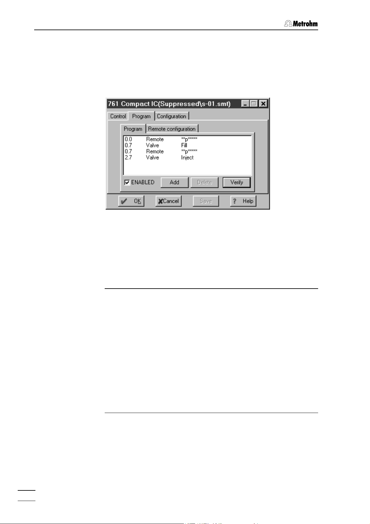
4 Operation
Time program
On the
Program tab of the system settings window a user-defined time
program for instrument control can be entered. This program is started
automatically as defined in the
ther at the moment the determination is started (
or at the moment the sample is injected (
Start mode window (see section 4.3.3) ei-
Start with determination)
Start with inject).
The
Program tab contains the two following subpages:
Program Main time program with all program steps.
Remote configuration Possibility for creation of user-defined remote
commands.
Program
On the
Program subpage, program steps including time, program in-
struction and parameter can be entered.
Time (1st column) Time at which program instruction is applied.
Entry range: 0.0 ... 999.9 min
If no time is entered, the program instruction is
applied together with the last instruction with
time entry.
Command (2nd column) Program instruction (see List of program in-
structions).
In addition to these predefined instructions,
user-defined remote commands can be entered if activated on the
Remote configuration
tab.
Parameter (3rd column) Parameter for program instruction (see List of
program instructions).
ENABLED Enable program start (a disabled program is
not started).
<Add> Add new program instruction.
<Delete> Delete selected program instruction.
<Verify> Test the time program (error messages are dis-
played if program is wrong).
761 Compact IC
88
Page 99

4.3 Systems
List of program instructions
The following program instructions can be added to the time program
on the
Instruction Parameter entry Meaning
Program subpage:
Valve Inject, Fill
FullScale
ICPump on, off
Flow 0.2 ... 2.5 mL/min
Pmax 0.0 ... 25.0 MPa
Pmin 0.0 ... 25.0 MPa
Remote 0, 1, *, p
50, 250, 1000 µS/cm
Switch injection valve to "INJECT" or
"FILL" position.
Set full scale range to the selected
value.
Switch on or off the high-pressure
pump.
Set flow rate of the high-pressure
pump to the desired value.
Set maximum pressure limit for the
high-pressure pump to the desired
value.
Set minimum pressure limit for the
high-pressure pump to the desired
value.
Set remote output lines 1...8 to the
desired values. For entry of the first
value, enter
1, 0, p or *. For entry of the
other values, move the cursor in front
of the value to be changed and enter
1, 0, p or *.
Program END, RESET
END flag can be used to end a
The
program, especially if the program
time should be longer than the
chromatogram duration. Additional
steps after this flag are not allowed.
The
RESET flag is used to reset the
parameters to the system startup
values.
Suppressor
Switch suppressor module to the
next position.
Peristaltic on, off
Switch on or off the peristaltic
pump.
Remote configuration
On the
Remote configuration subtab user-defined remote commands can
be defined, which can be inserted into a time program.
761 Compact IC
89
Page 100
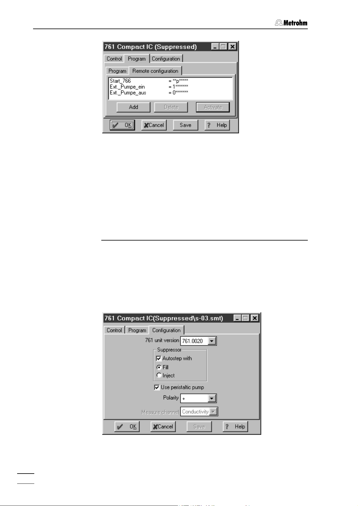
4 Operation
Name (1st column) User-definable name of the remote command
Start_766).
(e.g.
Remote command (2nd column)
Setting the remote output lines 1…8.
Selection:
For entry of the first value, enter
0 (line off, inactive, open)
1 (line on, active, 0 V)
p (pulse)
* (leave line in current status)
1, 0, p or *. For
entry of the other values, move the cursor in
front of the value to be changed and enter
p or *.
1, 0,
<Add> Add new remote command.
<Delete> Delete selected remote command.
<Activate> Activate the defined remote commands for in-
sertion into the time program.
Configuration
The
Configuration tab in the system settings window contains configura-
tion settings for the 761 Compact IC.
761 unit version Selection of instrument version:
761.0010 761 Compact IC without suppressor
761.0020 761 Compact IC with suppressor
761 Compact IC
90
 Loading...