

Page 1
760 Sample Changer760 Sample Changer
Instructions for Use
8.760.1013
Page 2

CH-9101 Herisau/Switzerland
Phone +41 71 353 85 85
Fax +41 71 353 89 01
E-Mail info@metrohm.ch
Internet www.metrohm.ch
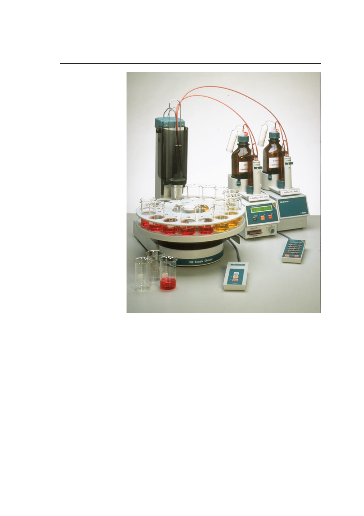
760 Sample Changer
Instructions for Use
8.760.1013
2000.07 up/dm
Page 3

Table of Contents
Page
1 OVERVIEW .................................................................1
1.1 Side View .................................................................... 1
1.2 Rear View ....................................................................2
1.3 Sensors ......................................................................3
2 INSTALLATION ............................................................4
2.1 Setting up the Instrument ...........................................4
2.2 Safety Considerations ................................................6
2.3 Arranging the Accessories .........................................7
2.3.1 Connecting the Keyboard ...................................7
2.3.2 Magnetic Stirrer ................................................. 7
2.3.3 Racks ............................................................... 7
2.3.4 Mounting and Setting up the Titration Heads ........ 8
2.3.5 Use of the sample beaker for Karl Fischer
Titration ........................................................... 10
2.4 Remote Connections ............................................... 11
2.4.1 Typical Combinations of Instruments ................ 12
2.5 Racks ........................................................................ 14
3 INTRODUCTION .........................................................15
3.1 Important Features ................................................... 15
3.2 Key Functions ........................................................... 16
3.3 Memory Initialization ................................................ 17
3.4 Configuration Procedure .......................................... 17
3.4 The Methods ............................................................. 20
4 APPENDIX ................................................................23
4.1 Error Messages ......................................................... 23
4.2 Method Listings ........................................................ 25
4.3 Technical Specifications ........................................... 29
4.4 Servicing and Maintenance ....................................... 30
4.4.1 Servicing ......................................................... 30
4.4.2 Maintenance / Attendance ................................ 30
4.5 Warranty and Conformity ......................................... 31
4.5.1 Warranty ......................................................... 31
4.5.2 Certificate of Conformity .................................. 32
4.6 Accessories .............................................................. 34
5 INDEX......................................................................37
Page 4
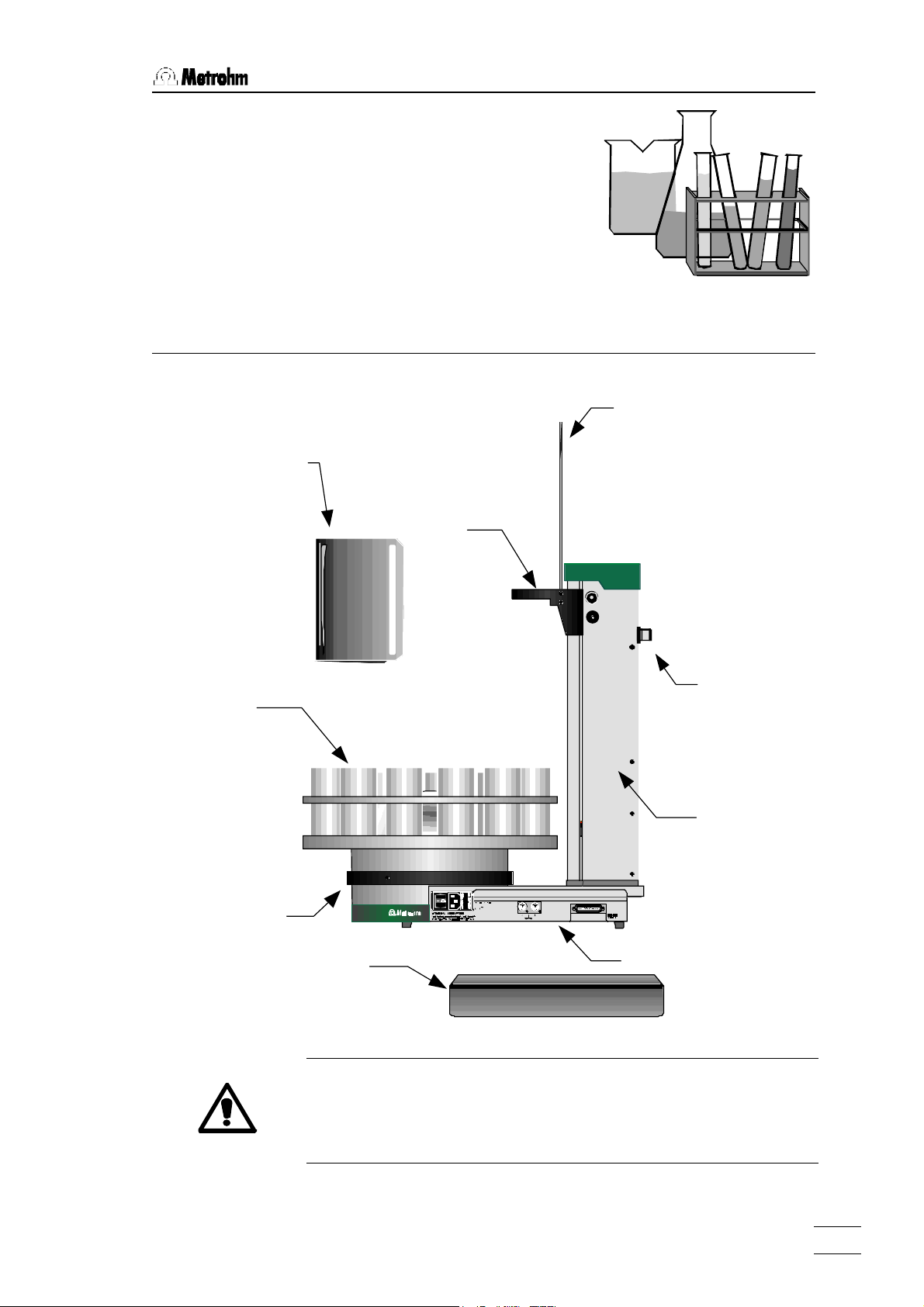
1.1 Side View
Plug cover
Rack
Line sleeve
Line frame
Tower
Connectors
Stirrer rail
1 Overview
1.1 Side View
Splash protection
Lift
760 Sample Changer, Overview
Safety note:
Never operate the 760 Sample Changer without splash protection
and plug cover being mounted. The plug cover prevents any contamination of the connectors, caused by spilled solvents or chemicals.
1
Page 5
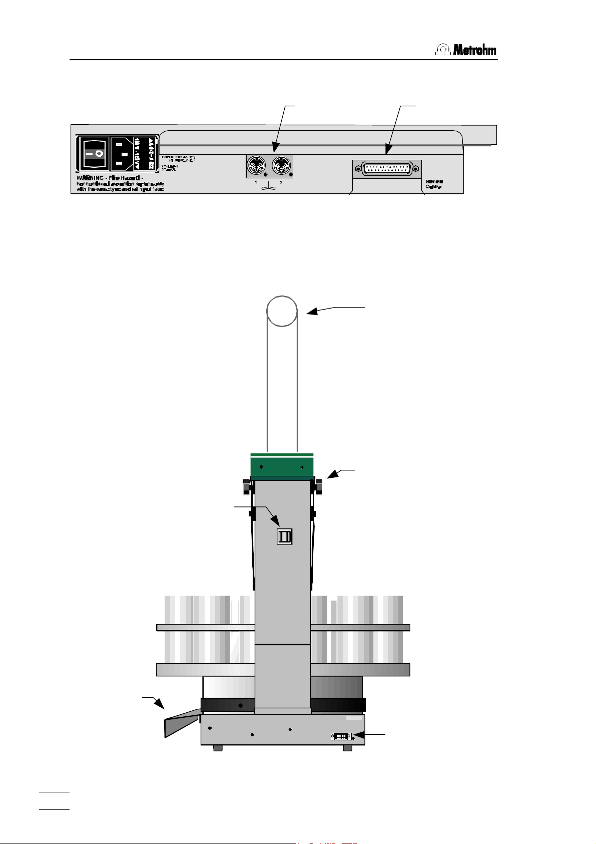
1.2 Rear View
Remote socket
Line sleeve
Plug cover
Keyboard connector
Line frame
The Connectors (side view):
Stirrer sockets
The remote socket serves the connection of Metrohm- or other
measuring instruments that communicate via a parallel cable
(see p. 11).
1.2 Rear View
Type 1.760.0010 Nr. 0010/01104
Keyboard
Made by Metrohm Herisau Switzerland
Mounting srew
for splash protection
760 Sample Changer, Overview
2
Page 6
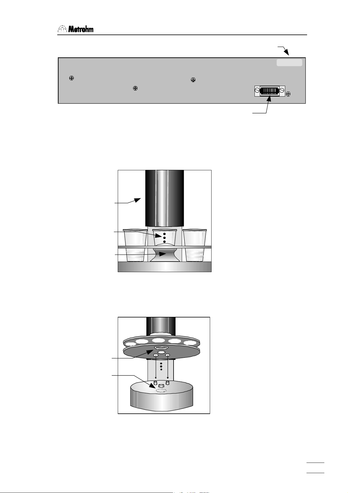
1.3 Sensors
Keyboard connector
Splash protection
Beaker indicator
Rack
Magnetic indicator
Manufacturing number
Magnet holder
Keyboard Connector (rear):
Type 1.760.0010 Nr. 0010/01104
Keyboard
1.3 Sensors
Beaker test
Made by Metrohm Herisau Switzerland
Each tower of the 760 Sample
Changer is equipped with a
beaker indicator to detect the
presence of a beaker in front
of the tower. This infrared
sensor detects many different
materials, if any object is
placed in correct position. This
beaker test is carried out after
each MOVE operation.
Front view
Magnetic rack code indicator
The magnetic sensor for the
detection of the individual rack
codes is mounted below the
sample changer's turntable.
The magnetic binary code of
the racks can only be read, if
the rack is in initial position
and therefore the magnet
holder is in accurate position
right above the rack code indicator. For this reason the
760 Sample Changer should
be initialized by <RESET> or
turned off and on right after
every rack change.
760 Sample Changer, Overview
3
Page 7
2.1 Setting up the Instrument
2 Installation
2.1 Setting up the Instrument
Packaging
The 760 Sample Changer is supplied with the accessories in separate special packages designed to ensure maximum protection.
These contain shock-absorbing foam linings. As only these special
packages guarantee damage-free transport of the instrument, it is
essential you store them in a safe place.
Control
Immediately following delivery, check that the consignment is
complete and undamaged (compare with delivery note and accessories list in the Instructions for Use, page 34). In case of damage
see "Warranty", page 31.
Setting up
The 760 Sample Changer is a rugged instrument and may be used
in rough environments such as laboratories and manufacturing
plants. It must not be exposed to a corrosive atmosphere. If the
sample changer is operated in a rough environment, regular maintenance is strongly recommended.
Power Supply
Follow these instructions to connect the 760 Sample Changer to
the power supply. Ensure that the instrument is never operated
with incorrect voltage ratings and/or with fuses of an incorrect rating, otherwise there is a fire hazard!
Setting the instrument supply voltage
Before switching on the 760 Sample Changer for the first time,
check that the line voltage set on the instrument (see next page)
matches the local power supply voltage. If this is not the case,
change the voltage setting as follows:
760 Sample Changer, Installation
4
Page 8
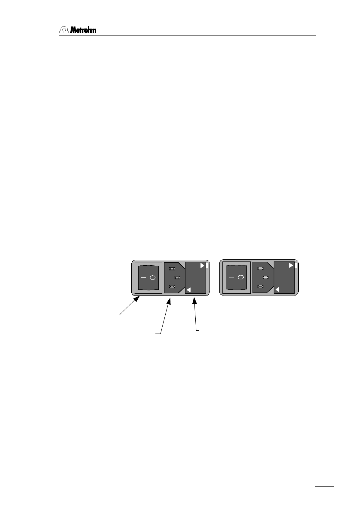
0 Power Supply
100 – 120 V
220 – 240 V
Fuse holder
• Disconnect line cable
Unplug the 760 Sample Changer.
• Remove fuse holder
Using a screw driver, loosen the fuse holder and pull it out.
• Checking and replacing fuse
Carefully remove the built-in fuse and check its specifications.
(The position of the fuse in the fuse holder is marked by the
white arrow printed next to the supply voltage):
100……120 V 0.5 A (slow) ord. no. U.600.0014
220……240 V 0.25 A (slow) ord. no. U.600.0011
• Replace fuse
Replace fuse if necessary and reinsert it in the fuse holder.
• Insert the fuse holder
Insert the fuse holder according to the appropriate supply voltage. The white arrow besides the desired voltage has to point
towards the white block mark printed on the fuse holder's panel
(see below).
100
-
-
120 V
240 V
-
-
220
220
-
-
240 V
120 V
-
-
100
Power switch
Power plug
760 Sample Changer, Installation
5
Page 9
2.2 Safety Considerations
2.2 Safety Considerations
Safety note:
Never operate the 760 Sample Changer without splash protection
and plug cover being mounted. The plug cover prevents any contamination of the connectors, caused by spilled solvents or chemicals.
If failure or malfunctioning occurs during operation of the 760 Sample Changer, the Metrohm Service Department should be
consulted.
If opening the instrument is unavoidable, the following safety precautions are to be strictly adhered to:
Before opening the instrument disconnect it from all electrical sources. Make sure that the power plug has been pulled
out.
Electronic components are sensitive to static electricity and can be
destroyed by discharge. Before touching any components inside
the instrument, both the person and his tools should be grounded
by grasping a grounded object (for example: a metallic part of the
casing of the instrument or a radiator) in order to eliminate any
static electricity.
Only in exceptional cases should the instrument be opened while it
is switched on. Because parts that conduct current are exposed in
this case, this should only be undertaken by an expert who is acquainted with the associated dangers.
When peripheral instruments are connected to the 760 Sample
Changer, the sample changer and the instruments to be connected
have to be switched off, otherwise all instruments could suffer
damage.
If it becomes apparent that the instrument can no longer be operated safely, it must be put out of operation.
760 Sample Changer, Installation
6
Page 10
2.3 Arranging the Accessories
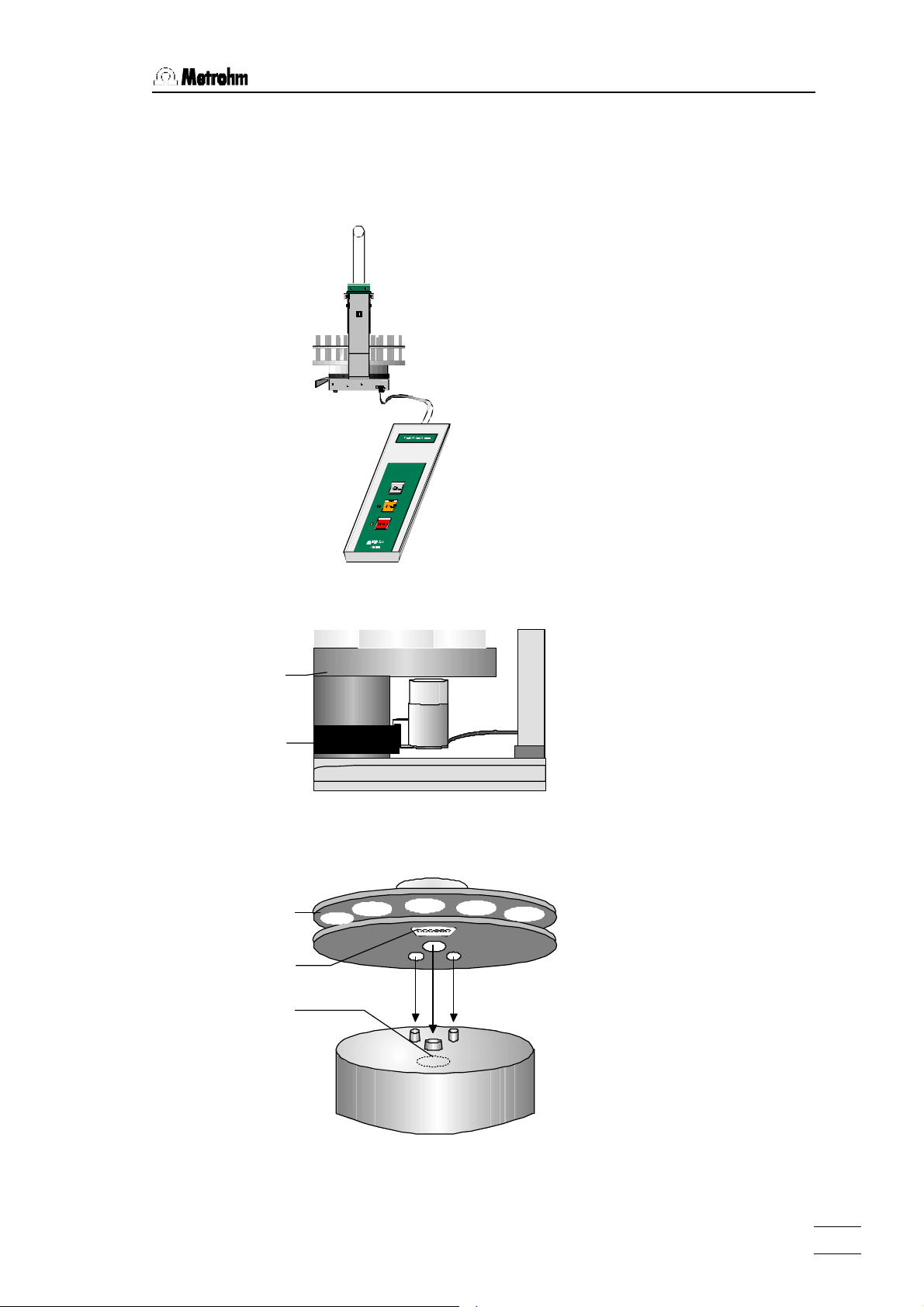
Rack
Magnet holder
Magnetic sensor
Rack
2.3 Arranging the Accessories
2.3.1 Connecting the Keyboard
Type 1.760.0010 Nr. 0010/01104
Keyboard
Made by Metrohm Herisau Switzerland
The keyboard is to be connected to the keyboard
socket on the rear side of the
sample changer.
To disconnect press the plug
together slightly on both
sides.
2.3.2 Magnetic Stirrer
Stirrer rail
2.3.3 Racks
Magnetic stirrers 2.741.0010
may be placed in any position
on the stirrer rail beneath the
rack.
After placing the rack on the
turntable, the sample
changer must be initialized by
pressing the <RESET> key
or turning the sampler
changer off and on. This
enables the safe reading of
the magnetic rack code and
can only be done if rack
position 1 is directed to
tower 1. Before a rack is
used for the first time, the lift
positions have to be set (s.
Chapter. 3.4).
760 Sample Changer, Installation
7
Page 11
2.3 Arranging the Accessories
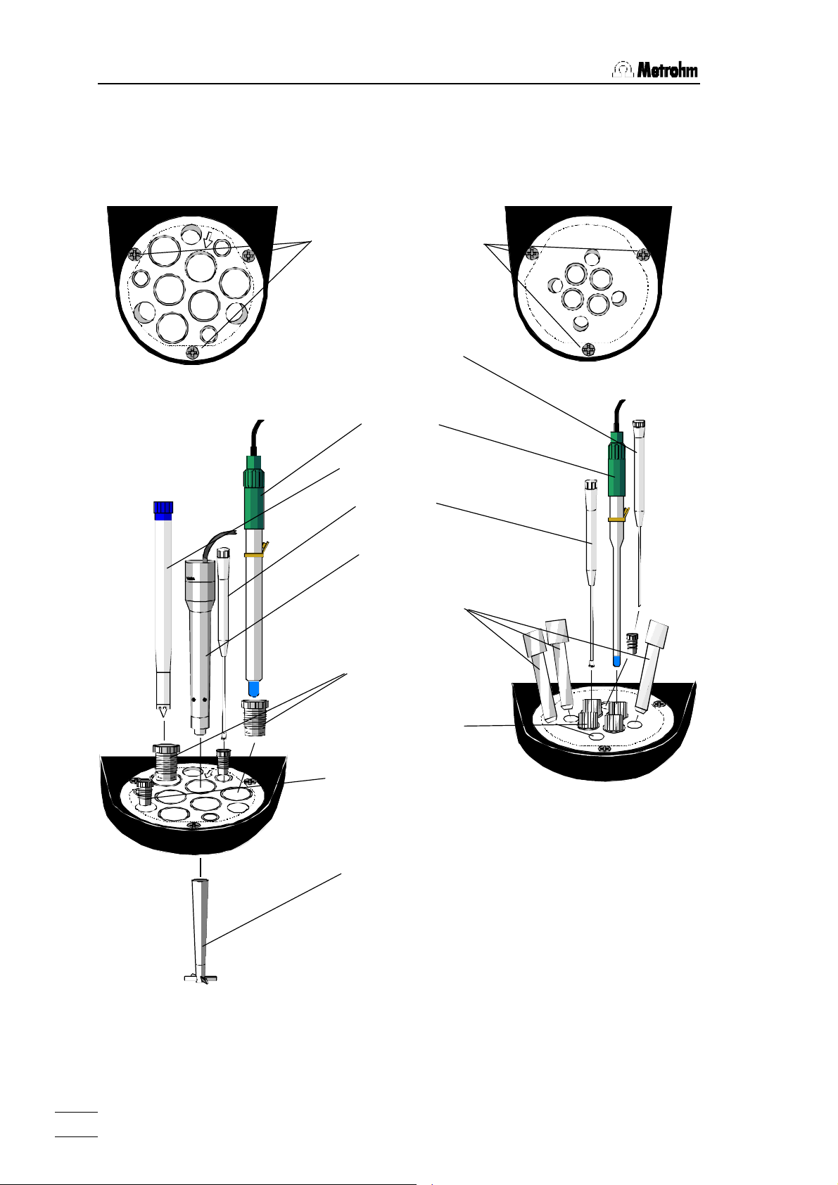
2.3.4 Mounting and Setting up the Titration Heads
Macro Titration head
6.1458.010
Micro Titration head
Mounting screws
M8 Aspiration tip
(also for Macro Titration head)
6.1543.170
Electrode
Rotating nozzle
6.2740.000
Burette tip
6.1543.200
Rod stirrer
2.722.0020
M6 Spray nozzles
(also for Macro-Titration head)
6.2740.020
SGJ14 sleeve
6.1236.020
M8 Thread stopper
4.658.0180
SGJ9 Guide sleeve
6.2709.070
Stirrer propeller
6.1909.020
6.1458.020
Use only the designated
Micro electrodes with the
Micro Titration head, see
accessory list, page 34.
Note on Macro Titration head
The arrow sign marks the slightly sloped SGJ14 boring, which enables to center a rod
stirrer or an electrode in a narrow titration vessel.
760 Sample Changer, Installation
8
Page 12
2.3 Arranging the Accessories
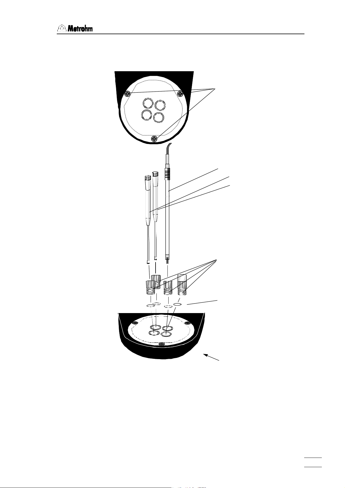
Mounting and Setting up the Titration head KFT
Titration head KFT
6.1458.030
Mounting screws
Double-Pt-Electrode
Burette tips
6.0340.000
6.1543.200
M10 Thread connectors
6.1543.200
O-Rings
E.301.0022
O-Ring (bottom side)
E.301.0080
Note:
For an optimal sealing of the titration vessel, the M10 thread con-
nectors should be mounted together with the O-rings.
All tubing and cables connected to the titration head should be
guided through the line frame to ensure full motility for the lift.
Note that there is enough line reserve for a complete down
movement of the lift.
760 Sample Changer, Installation
9
Page 13

2.3 Arranging the Accessories
Al foil
2.3.5 Use of the Sample Beaker for Karl Fischer Titration
For Karl Fischer titration the
Foil holder
6.2037.040
Sample beaker
During the method run the lift is moved down to the working
position. Thereby, the electrode and burette tips break through the
Al foil. Using Al foil 6.2820.000 this means no risk for the
instruments. This step can be facilitated by binding together all three
devices approx. 2 cm above the bottom of electrode and
burette tips using an O-ring E.301.0022. Thus, the impulse is
focused on a small area of the Al foil.
weighted sample is dosed into
the sample beaker together with
a stirring bar 6.1903.010.
The beaker is sealed with a
centered aluminium foil
6.2820.000 using the foil holder.
760 Sample Changer, Installation
10
Page 14

2.4 Remote Connections
2.4 Remote Connections
Remote
Dosimat
Titrino
Family
765
776
702
716
718
719
720
736
751
758
784
785
Valves
760 Sample Changer
Relay Box 731
Pumps,
e.g. 772
Connecting peripheral instruments to the 760 Sample Changer requires Metrohm cables. Otherwise a safe data transmission may
not be guaranteed.
The required cables are listed in the following table. Details about
the control commands are given in the Instructions for Use of the
corresponding instrument.
Connection of: Cable ordering no.
Titrino or 692/712/713 pH-Meter/Ionmeter/Conductometer 6.2141.020
Titrino and 765 or 776 Dosimat 6.2141.040
691 pH-Meter 6.2141.060
692 Ionmeter and 765 Dosimat 6.2141.070
678/682/686/672 Titroprocessors 3.980.3640
678/682/686/672 Titroprocessors and 671 Switch Box 3.980.3650
All instruments have to be switched off, before they are connected.
Otherwise the instruments could suffer from damage.
760 Sample Changer, Installation
11
Page 15

2.4 Remote Connections
Cable 6.2141.020
Inputs
Outputs
14 lines (Output 0–13) are available for the emission of signals.
For receiving signals 8 lines are provided (Input 0–7). The
assignment of these lines is fixed for the 760 Sample Changer.
Pin assignment of the Remote socket:
0 Volt
+5 Volt
Output 5
Output 3
Output 1
Output 12
Output 13
Input 0
Input 2
Input 4
Input 6
0 Volt
Output 6
Output 7
Output 4
Output 2
Output 0
Output 8
Output 9
Output 10
Input 1
Input 3
Input 5
Input 7
Output 11
The +5 V supply line may by charged with 20 mA maximally.
2.4.1 Typical Combinations of Instruments
760 Sample Changer — Titrino
with standard cable
+5V
active = low
inactive = high
active = low
inactive = high
760 Sample Changer, Installation
12
B
A
Titrino
C
D
Remote control commands:
Output 0: *************1 starts Titrino
Input 3: ****1*** awaits end of titration (EOD pulse)
Page 16

2.4 Remote Connections
760 Sample Changer — Titrino — Dosimat 765/776
B
A
Titrino
A
765
C
D
Cable 6.2141.040
D
B
C
Remote control commands:
Output 0: *************1 starts Titrino
Output 6: *******1****** starts Dosimat
Input 3: ****1*** awaits end of titration (EOD pulse)
Pump Control via Remote Lines
Using methods 3 and 4, external pumps can be controlled via the
remote interface. To start a pump, an inverted pulse of duration of
at least 200 ms is sent to pin 7 (Output 9) of the remote socket.
To continue with the method the pump must indicate its readiness
by setting the input line 1 (pin 9) to low level for at least 20 ms.
Ask your pump distributor or Metrohm for customized connecting
cables.
Pin 9 Input
t
p
t
>20 ms
p
+5V
active = low
inactive = high
Pin 7 Output
V
t
p
CEO
t
>200 ms
p
= 40 V
active = low
inactive = high
IC = 20 mA
760 Sample Changer, Installation
13
Page 17

2.5 Racks
2.5 Racks
A sample rack is a sort of turntable for the positioning of beakers
which are to be placed on the Sample Changer. Because for titration, various sizes of beakers are common or required, many kinds
of racks can be used and are easily interchangeable. The rack offers space for various numbers of samples depending on the
diameter of the beakers. Metrohm delivers the following predefined
types of standard racks:
Type Number of
beakers
M12-0 12 250 mL Metrohm glass beaker 000001 6.2041.310
M12-0 12 150 mL glass beaker or
M14-0 14 200 mL disposable beaker (Euro) 000011 6.2041.370
M14-0 14 8 oz disposable beaker (US) 000101 6.2041.380
M16-0 16 150 mL glass beaker 000010 6.2041.320
M16-0 16 120 mL disposable beaker (US) 100001 6.2041.390
M24-0 24 75 mL Metrohm glass beaker 001000 6.2041.340
Type of beaker Predefined
Code
100000 6.2041.360
200 mL disposable beaker (Euro)
Every single rack can be identified by a unique magnetic code.
Rod magnets which are attached to the bottom of the rack can be
combined to form a 6-place binary code. The sample changer can
then automatically recognize the mounted rack. This is possible
when the rack is positioned with the first rack position under lift 1.
After changing a rack, the sample changer should first be initialized by pressing the <RESET> key or turning the instrument off
and on. This way the save recognition of a rack and therefore the
correct beaker positioning is made possible.
Order Number
760 Sample Changer, Installation
14
Page 18

3.1 Important Features
3 Introduction
3.1 Important Features
Overview
The 760 Sample Changer provides most of the important features
of the 730 Sample Changer:
• Interchangeable Metrohm standard sample racks
• Working, rinsing and shift heights can be specifically defined
• Automatic rack recognition by means of standard rack codes
• Optical beaker test
• Two stirrers (magnetic or rod stirrer) can be connected
• Operation with most Metrohm instruments via Remote I/O lines
LimitationsLimitations
• 4 fixed procedures that cannot be edited
• No RS 232 interface, no built-in pumps
• Simple keyboard with 3 keys and 2 LEDs (green and red)
• The turning speed of the rack cannot be varied
• No special rack types can be defined
Basic Settings
• Working, rinsing and shift heights can be defined for each rack
type
• Stirrer speed can be defined for both stirrers together
• One of 4 methods can be selected as the standard method
760 Sample Changer, Introduction
15
Page 19

3.2 Key Functions
3.2 Key Functions
The 760 Sample Changer operates in two different modes where
the keys provide different functions:
The Basic Mode starts when the instrument is turned on. The
ready-to-operate status is indicated by the green LED.
Basic Mode:
(after Power on, green LED on)
START
RESET
STOP
Starts processing of a sample series.
Stops processing of a sample series or initializes the
760 Sample Changer.
Interrupts processing of a sample series, green LED
HOLD
blinks.
START
Continues processing of a sample series.
The Configuration Procedure starts when the instrument is
switched on with pressing <HOLD> simultaneously. The green
LED blinks once. Now, the method can be selected and working,
rinsing and shift heights as well as the stirrer speed can be defined.
Configuration Procedure:
(after Power on with <HOLD> pressed, green LED blinks once)
Accepts the setting of a value and moves on to the
START
next value.
Learning mode, manual execution of a changer func-
HOLD
tion for setting a configuration.
RESET
STOP
760 Sample Changer, Introduction
16
Cancels a configuration setting and initializes the 760
when <STOP> is pressed twice. Switches back to
basic condition.
Page 20

3.3 Memory Initialization
3.3 Memory Initialization
The system memory can be initialized to set default parameters
when required (e.g. in the case of mal-functions). For this purpose
press all keys while the sample changer is switched on.
It is recommended to execute an initialization before the first installation of the sample changer.
RESET
START HOLD STOP
3.4 Configuration Procedure
The Configuration Procedure starts when the instrument is
switched on with pressing <HOLD> simultaneously. The method is
being selected and working, rinsing and shift heights are defined
and assigned to the selected rack type. Additionally, the stirrer
speed can be defined.
If the 760 Sample Changer is used for the first time, the lift positions have to be adapted to the selected rack type. This applies
also if a new rack type is inserted for the first time.
Empty beakers with a stirrer bar if necessary should be used for
the definition of the lift positions. Additionally, the foil holder has to
be used without Al foil if the Sample Changer is being set up for
Karl Fischer titration.
The working position should be defined in such a way that the
connected electrode tip stands in the center of the sample. The
shift position should allow a free rotation of the sample rack. In the
rinsing position, the aspiration tip should touch the bottom of the
sample beaker. If no rinsing step is necessary (method 1 and 2),
no rinsing position has to be defined.
In order to proceed to the next point in the configuration procedure,
<START> must be pressed. This accepts the current setting.
<STOP> is pressed in order to cancel a setting. The configuration
procedure is terminated by pressing <STOP> again.
The LEDs show either the status of the sample changer or the current step in the configuration procedure.
and "Power on"
760 Sample Changer, Introduction
17
Page 21

3.4 Configuration Procedure
The Configuration Procedure
Key LEDs Explanation
HOLD
+
"Power ON"
HOLD
START
HOLD
START
green 1∗
red 1-4∗
green 1∗
green 2∗
red blinks
green 2∗
green 3∗
In order to start the configuration procedure the <HOLD> key
must be pressed while the sample changer is switched on.
The green LED lights up once to show that the configuration
procedure is active. The method can now be selected.
When the <HOLD> key is pressed the red LED blinks once
for the first method. Each time <HOLD> is pressed again the
next method is selected up to method 4, then method 1
again.
<START> accepts the setting. The green LED blinks twice.
The working position of the lift can now be set.
When the <HOLD> key is pressed the lift can be moved
manually. Each further time the <HOLD> key is pressed the
direction in which the lift moves is altered. In this way the
working position can be set accurately.
<START> accepts the setting. The working position is stored
specifically for the type of rack inserted. The green LED
blinks three times. The rinsing position of the lift can now
be set.
HOLD
START
HOLD
START
red blinks
When the <HOLD> key is pressed the lift can be moved manually. Each further time the <HOLD> key is pressed the
direction in which the lift moves is altered.
green 3∗
green 4∗
red blinks
<START> accepts the settings. The rinsing position is stored
specifically for the type of rack inserted. The green LED
blinks four times. The shift position of the lift can now be
set.
When the <HOLD> key is pressed the lift can be moved manually. Each further time the <HOLD> key is pressed the
direction in which the lift moves is altered.
green 4∗
<START> accepts the setting. The shift position is stored
specifically for the type of rack inserted. The green LED
blinks five times. The stirrer speed can now be set.
green 5∗
760 Sample Changer, Introduction
18
Page 22

3.4 Configuration Procedure
HOLD
START
RESET
STOP
red blinks
The <HOLD> key switches on the stirrer(s). If the <HOLD>
key is kept pressed down the speed increases continuously.
If the <HOLD> key is pressed again the stirrer speed is reduced in a similar manner. In this way the stirrer speed can
green 5∗
be set accurately.
<START> accepts the setting. The configuration procedure
is now complete. It can be restarted by pressing <HOLD> in
order to select the method.
blinks
lights up
The configuration procedure is terminated with <STOP>.
When the green LED is illuminated the sample changer is in
the basic condition and is ready to process a series of samples.
The individual steps of the configuration procedure:
1∗ Method selection
2∗ Setting the working position
3∗ Setting the rinsing position
4∗ Setting the shift position
5∗ Setting the stirrer speed
760 Sample Changer, Introduction
19
Page 23

3.5 The Methods
3.5 The Methods
All methods enable the dosing of auxiliary solutions before the titration if a 765 or a 776 Dosimat is used. The dosing volume is to
be defined in the Dosimat. The Sample Changer will start the distribution via a remote line.
The following titration instruments can be used with the 760 Sample Changer: all of the Titrino models (701, 702, 716, 718, 719,
720, 736, 751, 758, 784, and 785) and the Titroprocessors. Simple
measuring series may be performed as well instead of titrations.
The supported Metrohm meters are: 691 and 713 pH-Meter, 692
pH/Ion Meter, 712 Conductometer.
In each method all rack positions will be processed. After the
treatment of the last sample the special beaker (highest rack position) is moved to the tower and the lift will be lowered to work position immersing the electrode for rinsing or conditioning.
Method 1 (for exact sequence, see Appendix, p. 25)
Plain working procedure without rinsing
Procedure:
1. move the sample beaker to the tower
2. run lift to work position
3. switch on stirrer
4. start dosing device
5. wait 10 seconds
6. start titrator
7. await end of determination
8. switch off stirrer
9. run lift to shift position
760 Sample Changer, Introduction
20
Page 24

3.5 The Methods
Method 2 (for exact sequence, see Appendix, p. 26)
Working procedure with sensor conditioning by dipping. The special beaker (highest rack position) must be filled before with solvent or water.
Procedure:
1. move the sample beaker to the tower
2. run lift to work position
3. switch on stirrer
4. start dosing device
5. wait 10 seconds
6. start titrator
7. await end of determination
8. switch off stirrer
9. run lift to shift position
10. get special beaker
11. run lift to work position
12. switch on the stirrer for 5 seconds
13. run lift to shift position
Method 3 (for exact sequence, see Appendix, p. 27)
Working procedure with sensor rinsing in a special beaker using
an external pump.
Procedure:
1. move the sample beaker to the tower
2. run lift to work position
3. switch on stirrer
4. start dosing device
5. wait 10 seconds
6. start titrator
7. await end of determination
8. switch off stirrer
9. run lift to shift position
10. get special beaker
11. run lift to work position
12. switch on the external pump
13. await readiness of the pump
14. run lift to shift position
760 Sample Changer, Introduction
21
Page 25

3.5 The Methods
Method 4 (for exact sequence, see Appendix, p. 28)
Working procedure with sensor rinsing in the sample beaker using
an external pump.
Procedure:
1. move the sample beaker to the tower
2. run lift to work position
3. switch on stirrer
4. start dosing device
5. wait 10 seconds
6. start titrator
7. await end of determination
8. switch off stirrer
9. run lift to rinse position
10. switch on the external pump
11. await readiness of the pump
12. run lift to shift position
760 Sample Changer, Introduction
22
Page 26

4.1 Error Messages
4 Appendix
4.1 Error Messages
An error occurring during a sample series is displayed by a blinking red LED. The number of flashes indicates the error number.
This must be acknowledged with any key. If an error occurs during
processing of a sample series, the changer will then be switched
into the 'HOLD' state.
After the cause of the error has been rectified, the sample series
can be continued with the next command in the active sequence
by pressing the <START> key. If the error cannot be eliminated,
the method running can also be halted with <STOP>.
The list of possible error messages and their causes:
1* RAM defect Call Metrohm-Service.
3* battery low The battery for the permanent storage of user meth-
ods must be replaced.
4* manual stop The Sample Changer has been stopped manually.
No acknowledgement needed.
6* changer low power The power supply cannot deliver enough power for
the simultaneous operation of all components currently in use (stirrer, pumps, lifts).
7* rack data missing No sample rack is in position or no rack data can be
found for the sample rack that is in place.
8* invalid rack code The rack code read by the changer could not be
found in the internal position tables.
760 Sample Changer, Appendix
23
Page 27

4.1 Error Messages
9* missing beaker After a MOVE command no beaker could be found at
the selected position.
10* raise lift first Turning of a rack could not be carried out because a
lift was below the defined shift position.
12* changer overload Load or resistance too large to carry out the chosen
action.
14* changer not ready The changer cannot execute the command chosen
because it is busy carrying out another action.
760 Sample Changer, Appendix
24
Page 28

4.2 Method Listings
4.2 Method Listings
All four methods of the 760 Sample Changer are briefly described in chapter 3.5 on
pages 20 to 22. The present chapter contains the exact program listings of these methods together with more detailed explanations.
Method 1
760 Sample Changer 760.0012
parameters
method 760_1
number of samples: rack
>start sequence
1 CTL:Rm: INIT
2 SAMPLE: - 1
3 SAMPLE: + 1
>sample sequence
1 MOVE 1 : sample
2 LIFT: 1 : work mm
3 STIR: * : ON s
4 CTL:Rm: START dos*
5 WAIT 10 s
6 CTL:Rm: START device1
7 SCN:Rm : End1
8 STIR: * : OFF s
9 LIFT: 1 : shift mm
10 WAIT 3 s
>final sequence
1 MOVE 1 : spec.1
2 LIFT: 1 : work mm
>changer settings
rack number 0
lift rate 25 mm/s
shift rate 20
shift direction: auto.
beaker test mode: single
on beaker error: MOVE
>stirring rates
stirrer 1 3
stirrer 2 3
>dosing unit def.
>manual stop
CTL Rmt: STOP device1
CTL RS232:
------------
¬ report header with program version
¬ method name
¬ number of samples (here full rack)
¬ initialize remote line
¬ initialize
sample position
¬ move next sample beaker to tower
¬ run lift with titration head to working position
¬ switch on stirrer
¬ start dosing device
¬ wait for 10 seconds
¬ start titrator
¬ wait for end of titration [EOD]
¬ switch off stirrer
¬ run lift with titration head to shift position
¬ wait for 3 seconds
¬ move special beaker to tower for conditioning
¬ run lift to work position to immerse sensor
------ settings of sampler functions --------------------
¬ on missing sample beaker, the next one is
selected automatically
------ stirring rates ----------------------------------------¬ cannot be selected independently
------ settings for dosing devices ------------------------
------ action after manual stop ------------------------¬ stop device 1
760 Sample Changer, Appendix
25
Page 29

4.2 Method Listings
Method 2
760 Sample Changer 760.0012
parameters
method 760_2
number of samples: rack
>start sequence
1 CTL:Rm: INIT
2 SAMPLE: - 1
3 SAMPLE: + 1
>sample sequence
1 SHIFTRATE: + 20
2 MOVE 1 : sample
3 LIFT: 1 : work mm
4 STIR: * : ON s
5 CTL:Rm: START dos*
6 WAIT 10 s
7 CTL:Rm: START device1
8 SCN:Rm : End1
9 STIR: * : OFF s
10 LIFT: 1 : shift mm
11 WAIT 3 s
12 SHIFTRATE: - 20
13 MOVE 1 : spec.1
14 LIFT: 1 : work mm
15 STIR: * : ON s
16 WAIT 5 s
17 STIR: * : OFF s
18 LIFT: 1 : shift mm
19 WAIT 3 s
>final sequence
1 MOVE 1 : spec.1
2 LIFT: 1 : work mm
>changer settings
rack number 0
lift rate 25 mm/s
shift rate 20
shift direction: auto.
beaker test mode: single
on beaker error: MOVE
>stirring rates
stirrer 1 3
stirrer 2 3
>dosing unit def.
>manual stop
CTL Rmt: STOP device1
CTL RS232:
------------
¬ report header with program version
¬ method name
¬ number of samples (here full rack)
¬ initialize remote line
¬ initialize
sample position
¬ shift direction to increasing numbers
¬ move next sample beaker to tower
¬ run lift with titration head to working position
¬ switch on stirrer
¬ start dosing device
¬ wait for 10 seconds
¬ start titrator
¬ wait for end of titration [EOD]
¬ switch off stirrer
¬ run lift with titration head to shift position
¬ wait for 3 seconds
¬ shift direction to decreasing numbers
¬ move special beaker to tower
¬ run lift to work position to immerse sensor
¬ switch on stirrer
¬ wait for 5 seconds
¬ switch off stirrer
¬ run lift to shift position
¬ wait for 3 seconds
¬ move special beaker to tower for conditioning
¬ run lift to work position to immerse sensor
------ settings of sampler functions --------------------
¬ on missing sample beaker, the next one is
selected automatically
------ stirring rates ----------------------------------------¬ cannot be selected independently
------ settings for dosing devices ------------------------
------ action after manual stop ------------------------¬ stop device 1
760 Sample Changer, Appendix
26
Page 30

4.2 Method Listings
Methode 3
760 Sample Changer 760.0012
parameters
method 760_3
number of samples: rack
>start sequence
1 CTL:Rm: INIT
2 SAMPLE: - 1
3 SAMPLE: + 1
>sample sequence
1 SHIFTRATE: + 20
2 MOVE 1 : sample
3 LIFT: 1 : work mm
4 STIR: * : ON s
5 CTL:Rm: START dos*
6 WAIT 10 s
7 CTL:Rm: START device1
8 SCN:Rm : End1
9 STIR: * : OFF s
10 LIFT: 1 : shift mm
11 WAIT 3 s
12 SHIFTRATE: - 20
13 MOVE 1 : spec.1
14 LIFT: 1 : work mm
15 CTL:Rm: ****1*********
16 CTL:Rm: ****0*********
17 SCN:Rm : ******1*
18 LIFT: 1 : shift mm
19 WAIT 3 s
>final sequence
1 MOVE 1 : spec.1
2 LIFT: 1 : work mm
>changer settings
rack number 0
lift rate 25 mm/s
shift rate 20
shift direction: auto.
Beaker test mode: single
on beaker error: MOVE
>stirring rates
stirrer 1 3
stirrer 2 3
>dosing unit def.
>manual stop
CTL Rmt: STOP device1
CTL RS232:
------------
report header with program version
¬ method name
¬ number of samples (here full rack)
¬ initialize remote line
¬ initialize
sample position
¬ shift direction to increasing numbers
¬ move next sample beaker to tower
¬ run lift with titration head to working position
¬ switch on stirrer
¬ start dosing device
¬ wait for 10 seconds
¬ start titrator
¬ wait for end of titration [EOD]
¬ switch off stirrer
¬ run lift with titration head to shift position
¬ wait for 3 seconds
¬ shift direction to decreasing numbers
¬ move special beaker to tower
¬ run lift to work position to immerse sensor
¬ switch on external pump
¬ reset remote line
¬ wait for ready signal of pump
¬ run lift to shift position
¬ wait for 3 seconds
¬ move special beaker to tower for conditioning
¬ run lift to work position to immerse sensor
------ settings of sampler functions --------------------
¬ on missing sample beaker, the next one is
selected automatically
------ stirring rates ----------------------------------------¬ cannot be selected independently
------ settings for dosing devices ------------------------
------ action after manual stop ------------------------¬ stop device 1
760 Sample Changer, Appendix
27
Page 31

4.2 Method Listings
Methode 4
760 Sample Changer 760.0012
parameters
method 760_4
number of samples: rack
>start sequence
1 CTL:Rm: INIT
2 SAMPLE: - 1
3 SAMPLE: + 1
>sample sequence
1 MOVE 1 : sample
2 LIFT: 1 : work mm
3 STIR: * : ON s
4 CTL:Rm: START dos*
5 WAIT 10 s
6 CTL:Rm: START device1
7 SCN:Rm : End1
8 STIR: * : OFF s
9 LIFT: 1 : rinse mm
10 CTL:Rm: ****1*********
11 CTL:Rm: ****0*********
12 SCN:Rm : ******1*
13 LIFT: 1 : shift mm
14 WAIT 3 s
>final sequence
1 MOVE 1 : spec.1
2 LIFT: 1 : work mm
>changer settings
rack number 0
lift rate 1 25 mm/s
shift rate 20
shift direction: auto.
beaker test mode: single
on beaker error: MOVE
>stirring rates
stirrer 1 3
stirrer 2 3
>dosing unit def.
>manual stop
CTL Rmt: STOP device1
CTL RS232:
------------
¬ report header with program version
¬ method name
¬ number of samples (here full rack)
¬ initialize remote line
¬ initialize
sample position
¬ move next sample beaker to tower
¬ run lift with titration head to working position
¬ switch on stirrer
¬ start dosing device
¬ wait for 10 seconds
¬ start titrator
¬ wait for end of titration [EOD]
¬ switch off stirrer
¬ run lift with titration head to shift position
¬ switch on external pump
¬ reset remote line
¬ wait for ready signal of pump
¬ run lift to shift position
¬ wait for 3 seconds
¬ move special beaker to tower for conditioning
¬ run lift to work position to immerse sensor
------ settings of sampler functions --------------------
¬ on missing sample beaker, the next one is
selected automatically
------ stirring rates ----------------------------------------¬ cannot be selected independently
------ settings for dosing devices ------------------------
------ action after manual stop ------------------------¬ stop device 1
760 Sample Changer, Appendix
28
Page 32

4.3 Technical Specifications
4.3 Technical Specifications
Dimensions Height: 0.79 m, Width: 0.28 m, Depth: 0.48 m
Weight 12.5 kg
Material Sample Changer case: metal case, multiple enamelling
Splash protection: Polymethylene methacrylate (PMMA)
Sample rack: Acrylnitrile butadiene styrene (ABS)
or Polypropylene (PP)
Lift path 235 mm
Lift Load: approx. 10 N
Stroke speed: adjustable, 3...25 mm/s
Turntable Turning speed: 20 angular degrees/s
Stirrer Stirring rate: adjustable to 15 levels
- magnet stirrer 180/min...2600/min
- rod stirrer 180/min...3000/min
Remote Interface Programmable parallel interface for controlling external
instruments
t
p
Input:
t
>20 ms
p
t
Output:
V
p
CEO
t
>200 ms
p
= 40 V
IC = 20 mA
+5 V: maximum load = 20 mA
Temperatures Nominal functional range 5...40 °C at 20…80% rel. humidity
Transport und storage –20...+60 °C
60 °C rel. humidity < 50%
50 °C rel. humidity < 85%
40 °C rel. humidity <95%
Power connection Voltage 100...120 V, 220...240 V
Frequency 50...60 Hz
Power input 40 VA
Fuses 0.5 AT (110 V), 0.25 AT (220 V)
+5V
active = low
inactive = high
active = low
inactive = high
All data are typical values with the exception of those specially marked.
Safety Specifications
Constructed and tested according to IEC 1010 / EN 61010 /
UL 3101-1, Safety Class III
Degree of protection IP 22
The instruction manual contains information and warnings which
the user should follow to guarantee the safe operation of the instrument.
760 Sample Changer, Appendix
29
Page 33

4.4 Servicing and Maintenance
Electromagnetic Compatibility (EMC)
Emitted Interference: The instrument complies with the basic specifications
EN 50081-1/2 1992, EN 55011 (class B), EN 55022 (class B).
Interference immunity: The basic specifications EN 50082-1 1997, and IEC 801-2 to
IEC 801-4 are adhered to.
4.4 Servicing and Maintenance
4.4.1 Servicing
The maintenance of the 760 Sample Changer should include a
yearly service check carried out by a specialist from Metrohm. If
caustic or corrosive chemicals are frequently used, shorter time intervals between service checks can be necessary.
The Metrohm Service Department can offer technical advice
regarding servicing and maintenance of all Metrohm instruments at
any time.
4.4.2 Maintenance / Attendance
Not only highly sensitive measuring instruments do require proper
care, a sample changer also requires this. Serious contaminations
can lead to functional disorders and a shortened life-span of the
rugged mechanics and electronics of the sample changer.
Heavy soiling of the titration heads can influence the results of
measurements. Regular cleaning of exposed parts can prevent
this for the most part.
Chemical or solvent spills should be cleaned up immediately. The
connectors (in particular the power supply) should be protected
from contamination. The sample changer should never be operated without the covering foreseen for this purpose.
If corrosive media has entered the inside of the instrument, the
power plug has to be disconnected immediately to avoid massive
damage to the instruments electronic components. In case of such
damage, the Metrohm service personnel should be notified.
The instrument should not be opened by untrained personnel.
760 Sample Changer, Appendix
30
Page 34

4.5 Warranty and Conformity
4.5 Warranty and ConformityWarranty and Conformity
4.5.1 Warranty
The warranty on our products is limited to defects that are traceable to material, construction or manufacturing error which occur
within 12 months from the day of delivery. In this case, the defects
will be rectified in our workshops free of charge. Transport costs
are to be paid by the customer.
For day and night operation, the warranty is limited to 6 months.
Glass breakage in the case of electrodes or other parts is not cov-
ered by the warranty. Checks which are not a result of material or
manufacturing faults are also charged during the warranty period.
For parts of outside manufacture insofar as these constitute an
appreciable part of our instrument, the warranty stipulations of the
manufacturer in question apply.
With the regard to the guarantee of accuracy, the technical specifications in the instruction manual are authoritative.
Concerning defects in material, construction or design as well as
the absence of guaranteed features, the orderer has no rights or
claims except those mentioned above.
If damage of the packaging is evident on receipt of a consignment
or if the goods show signs of transport damage after unpacking,
the carrier must be informed immediately and a written damage
report demanded. lack of an official damage report releases
Metrohm from any liability to pay compensation.
If any instruments and parts have to be returned, the original packaging should be used if at all possible. This applies above all to instruments, electrodes, burette cylinders and PTFE pistons. Before
embedment in wood shavings or similar material, the parts must
be packed in a dustproof package (for instruments, use of a plastic
bag is imperative). If open assemblies are enclosed in the scope of
delivery that are sensitive to electromagnetic voltages (e.g. data
interfaces etc.) these must be returned in the associated original
protective packaging (e.g. conductive protective bag). (Exception:
assemblies with built-in voltage source belong in a non-conductive
protective packaging).
For damage which arises as a result of non-compliance with these
instructions, no warranty responsibility whatsoever will be accepted by Metrohm.
760 Sample Changer, Appendix
31
Page 35

4.5 Warranty and Conformity
4.5.2 Certificate of Conformity and System Validation for the
760 Sample Changer
This is to certify the conformity to the standard specifications for electrical
appliances and accessories, as well as to the standard specifications for
security and to system validation issued by the manufacturing company.
Name of commodity: 760 Sample Changer
System software: Stored in ROMs
Name of manufacturer: Metrohm Ltd., Herisau, Switzerland
Principal technical information: Voltages: 100…120, 220…240 V
Frequency: 50…60 Hz
This Metrohm instrument has been built and has undergone final type testing
according to the standards:
Electromagnetic compatibility
IEC 801-2 (level 3), IEC 801-3 (level 2), IEC 801-4 (level 3),
EN 55011 / class B, EN 55022 / class B, EN 50081-1/2 1992,
EN 50082-1 1997
Security specifications
IEC 1010, EN 61010, UL 3101-1
It has also been certified by the Swiss Electronical Association (SEV), which is
member of the International Certification Body (CB / IEC).
The technical specifications are documented in the instruction manual.
The system software, stored in Read Only Memories (ROMs) has been validated in connection with standard operating procedures in respect to functionality and performance. The features of the system software are documented in
the instruction manual.
Metrohm Ltd. is holder of the SQS certificate of the quality system ISO 9001
for quality assurance in design/development, production, installation and servicing.
Herisau, March 5th, 1998
Dr. J. Frank Ch. Buchmann
Development Manager Production and
Quality Assurance Manager
760 Sample Changer, Appendix
32
Page 36

4.5 Warranty and Conformity
Ionenanalytik • Analyse des ions • Ion analysis • Análisis iónico
760 Sample Changer
EU Declaration of Conformity
The Metrohm AG company, Herisau, Switzerland hereby certifies that the instrument:
760 Sample Changer
meets the requirements of EU Directives 89/336/EWG and 73/23/EWG.
Source of specifications:
EN 50081 Electromagnetic compatibility, basic specification Emitted Interference
EN 50082-1 Electromagnetic compatibility, basic specification Interference Immunity
EN 61010 Safety requirements for electrical laboratory measurement and control
equipment
Description of the instrument:
Sample changer for the automation of batch processing of larger sample series, applying titration, dosing and measuring methods in laboratory and industry.
Herisau, March 5th, 1998
Dr. J. Frank Ch. Buchmann
Development Manager Production and
Quality Assurance Manager
760 Sample Changer, Appendix
33
Page 37

4.6 Accessories
4.6 Accessories
760 Sample Changer 2.760.0010
includes the following accessories: Number
of pieces
SGJ14 sleeve 2 6.1236.020
FEP tubing connector M6 80cm 6.1805.110
Spiral band 7x0,75 0,5m 6.1815.010
Keyboard for 760 6.2142.100
Guiding sleeve 3 6.2709.070
Splash protection 6.2751.010
Plug cover 6.2752.010
Instructions for use 8.760.1013
760 Sample Changer KFT 2.760.0020
includes the following accessories: Number
of pieces
Magnetic stirrer 1.741.0010
Double Pt electrode 6.0340.000
Sample beaker 24 6.1432.210
Titration head for FKT 6.1458.030
FEP tubing connector M6 80cm 2 6.1805.110
Spiral band 7x0,75 0,5m 6.1815.010
Aspirating tube for 676 (Behr) 6.1821.000
Stirring bar 12mm 24 6.1903.010
Foil holder for beaker 6.1432.210 24 6.2037.040
Sample rack 24x75ml M24-0 6.2041.340
Cable 760-Titrino-765/776 6.2141.040
Keyboard for 760 6.2142.100
Splash protection 6.2751.010
Plug cover 6.2752.010
Al foil 0,010/80mm 1000 sheets 6.2820.000
O-ring 5,28/1,78 4 E.301.0022
O-ring 30/5 E.301.0080
Instructions for use 8.760.1013
760 Sample Changer, Appendix
34
Page 38

4.6 Accessories
Options
Accessories to separate order at additional charge:
722 Propeller Rod Stirrer for Sample Changer
Propeller rod stirrer 2.722.0020
Stirring propeller PP (104 mm) (incl.) 6.1909.020
741 Magnetic Stirrer
Magnetic stirrer 2.741.0010
Macro titration head (6 x SGJ 14, 3 x SGJ 9) 6.1458.010
Micro titration head (4 x M10) for rack 6.2041.340 6.1458.020
Sample Racks and Beakers
Sample Rack 12 x 250 mL M12-0 6.2041.310
Metrohm sample beaker glass 250 mL 6.1432.320
Metrohm sample beaker PP 200 mL 6.1453.220
Metrohm sample beaker PP 250 mL 6.1453.250
Sample Rack 12 x 150 mL M12-0 6.2041.360
for 150 mL standard beaker (high form) or
200 mL disposable beaker (Euro) PP 1000 pcs. 6.1459.310
Sample Rack 14 x 200 mL M14-0 6.2041.370
for 200 mL disposable beaker (Euro) PP 6.1459.310
Sample Rack 14 x 8 oz M14-0 6.2041.380
for disposable beaker (US) PP 8 oz
Sample Rack 16 x 150 mL M16-0 6.2041.320
for standard beaker (high form)
Sample Rack 16 x 120 mL M16-0 6.2041.390
for disposable beaker (US) 120 mL
Sample Rack 24 x 75 mL M24-0 6.2041.340
for Metrohm glass beaker 75 mL 6.1432.210
(Micro titration head necessary)
760 Sample Changer, Appendix
35
Page 39

4.6 Accessories
Electrodes for sample changer
For titrations with the macro titration head it is advisable to use
long life LL electrodes. Titrodes without standard ground joint
should be used with the SGJ sleeve 6.1236.040 made of silicone
rubber.
For direct titrations using the micro titration head, the following
special micro electrodes can be used:
LL Combined pH micro-electrode 16 cm 6.0234.110
Micro reference electrode Ag/AgCl 16 cm 6.0736.110
Micro pH glass electrode 16 cm 6.0134.110
Micro Ag-titrode 16 cm 6.0433.110
Micro-Pt-titrode 16 cm 6.0434.110
Micro Au-titrode 16 cm 6.0435.110
Pt 1000 Temperature sensor 16 cm 6.1110.110
Dosing Instruments
Dosimat 765 2.765.0010
Dosimat 776 2.776.0010
Exchange unit with ceramics stopcock 1 mL 6.3013.113
5 mL 6.3013.153
10 mL 6.3013.213
20 mL 6.3013.223
50 mL 6.3013.253
Exchange unit with PTFE stopcock 1 mL 6.3014.113
5 mL 6.3014.153
10 mL 6.3014.213
20 mL 6.3014.223
50 mL 6.3014.253
760 Sample Changer, Appendix
36
Page 40

5 Index
5 Index
A
Accessories...................... 34
Aluminium foil................... 10
Appendix.......................... 23
Aspiration tip......................8
B
Basic mode...................... 16
Basic settings................... 15
Battery............................. 23
Beaker test......................... 3
Burette tip..........................8
C
Certificate of Conformity.... 32
Configuration procedure.... 17
Connecting the keyboard.....7
Connectors.....................2, 3
D
Declaration of conformity... 33
Dimensions...................... 29
Dosimat ........................... 13
Dosing instruments........... 36
Double-Pt Electrode............9
E
Electrode.......................8, 36
Electrode rinsing............... 21
Electromagn. compatibility. 30
End of determ. (EOD) ....... 13
Environment.......................4
Error message.................. 23
External pump.............13, 22
F
Features .......................... 15
Foil holder........................ 10
Fuse..................................4
G
Guiding sleeve....................8
H
<HOLD> key .................... 16
I
Infrared sensor................... 3
Input ...........................11, 29
Installation..........................4
Instrument combinations ... 12
Instrument opening............. 6
Introduction...................... 15
K
Key functions.................... 16
Keyboard connector............ 3
KF sample beaker............. 10
KF titration head................. 9
L
LED................................. 16
Lift................................1, 29
Limitations........................ 15
Line frame...................... 1, 2
Line sleeve.....................1, 2
M
Macro titration head............ 8
Magnet holder ................ 3, 7
Magnetic sensor............. 3, 7
Magnetic stirrer...................7
Maintenance /Attendance.. 30
Manufacturing number ........3
Material............................ 29
Memory initialization ......... 17
Method listing................... 25
Methods........................... 20
Metrohm Service.............. 30
Micro electrode................... 8
Micro titration head .............8
Mounting screws.................8
O
Options............................ 35
O-Ring...............................9
Output.........................11, 29
Overview.......................1, 15
P
Packaging..........................4
parallel cable......................2
Pin assignment................. 11
Plug cover.......................... 1
Power connection............. 29
Power on.......................... 16
Power supply......................4
Procedure........................ 20
Pump control.................... 13
R
Rack.............................7, 14
Rack code.......................... 3
Rear view...........................2
Remote commands......12, 13
Remote connections .........11
Remote interface.........13, 29
Remote socket.............. 2, 11
Rinsing.............................21
Rinsing position................ 18
Rod stirrer..........................8
Rotating nozzle...................8
S
Safety considerations..........6
Safety measures.................6
Safety specification...........29
Sample beaker for KF
titration......................... 10
Sample rack................. 7, 14
Sensors..............................3
Servicing..........................30
Setting up....................... 4, 7
Shift position.....................18
Side view............................1
Signals............................. 11
Sleeves..............................8
Splash protection................1
Spray nozzle.......................8
Standard sample racks...... 14
<START> key................... 16
Stirrer...............................29
Stirrer propeller...................8
Stirrer rail....................... 1, 7
Stirrer sockets.....................2
Stirrer speed..................... 19
Stirring rate.......................29
<STOP> key.....................16
T
Technical specifications.....29
Temperatures................... 29
Thread stopper ...................8
Titration head .....................8
Titration head KFT..............9
Titrino..........................12, 13
Tower.................................1
Turntable.....................14, 29
W
Warranty and conformity....31
Weight ............................. 29
Working position...............18
760 Sample Changer, Index
37
 Loading...