

Page 1
1A
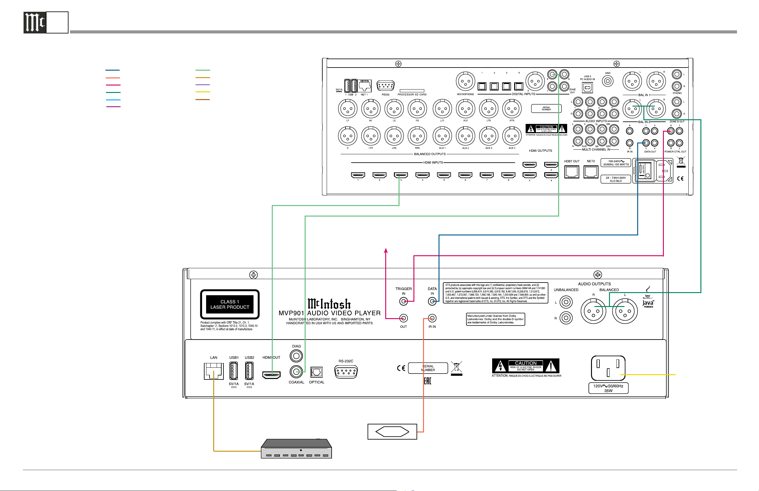
Note: Refer to the MVP901 Owner’s Manual page 11 for additional connection information.
Connection Legend:
Data Cable*- Digital Signal Cable Sensor/Keypad Cable - Network/RS232 Cable Power Control Cable* - Ground Wire Audio Signal Cable - AC Power Cords -
Video Signal Cable - Loudspeaker Cable RF Signal Cable -
* 2 conductor shielded with 1/8 inch stereo mini phone plug on each end.
MVP901 Connection Diagram
A/V Control Center
To TRIGGER
(Power Control) IN
on next Component
Connect to
AC Outlet
Network Modem or Router
McIntosh Laboratory, Inc. 2 Chambers Street Binghamton, New York 13903-2699 Phone: 607-723-3512 FAX: 607-724-0549 Part No. 04170700
IR Sensor
Page 2

1B
MVP901 Setup Menu
Figu re 2S
Figu re 3S
Figu re 5S
Figu re 6S
Figu re 4S
McIntosh Laboratory, Inc. 2 Chambers Street Binghamton, New York 13903-2699 Phone: 607-723-3512 FAX: 607-724-0549
Fig u re 1S
Figu re 7S
Page 3

1C
MVP901 Operation On-Screen Images
Figure 20S
Fig ure 21S
Figu re 23S
Figu re 24S
Figu re 26S
Figu re 27S
Figu re 29S
Figure 30S
Figu re 22S
McIntosh Laboratory, Inc. 2 Chambers Street Binghamton, New York 13903-2699 Phone: 607-723-3512 FAX: 607-724-0549 Part No. 04170700
Figu re 25S
Figure 28S
Fig u r e 31S
Page 4

1D
MVP901 Operation On-Screen Images
Figure 41S
Figure 32S
Figure 33S
Figure 35S
Figu re 36S
Figure 38S
Figu re 42S
Figure 39S
Figure 34S
McIntosh Laboratory, Inc. 2 Chambers Street Binghamton, New York 13903-2699 Phone: 607-723-3512 FAX: 607-724-0549
Figure 37S
Figure 43S
Figure 40S
Page 5

1E
MVP901 Operation On-Screen Images
Figu re 54S
Figu re 44S
Figure 45S
Figure 48S
Figu re 49S
Fig ure 51S
Figure 52S
Fig ure 55S
Figu re 56S
Figure 46S
Figure 47S
McIntosh Laboratory, Inc. 2 Chambers Street Binghamton, New York 13903-2699 Phone: 607-723-3512 FAX: 607-724-0549 Part No. 04170700
Figure 50S
Figure 57S
Figure 53S
Page 6

1F
MVP901 Operation On-Screen Images
Figure 70S
Figure 58S
Figure 59S
Figu re 62S
Figure 63S
Figu re 66S
Figu re 67S
Figure 60S
Figu re 64S
Figure 61S
Figu re 65S
McIntosh Laboratory, Inc. 2 Chambers Street Binghamton, New York 13903-2699 Phone: 607-723-3512 FAX: 607-724-0549
Figure 68S
Figu re 69S
 Loading...