

Page 1
AUDIO/VIDEO PLAYER
MVP861 AUDIO VIDEO PLAYER
COMPACT
SACD/CD
NEXT
AUDIO/VIDEO
BACK
FFREV
DVD
VIDEO
DIGITAL VIDEO
TITLE CHAPTER
CONTENTS
Performance Specifications ........................................ 2
Notes ......................................................................... 3
Safety Information ..................................................... 3
Rear Panel .................................................................. 5
Section Location ........................................................ 5
Block Diagram ........................................................... 6
Interconnection Diagram ...................................... 7 - 8
DIGITAL
SURROUND
PROGRESSIVE
STOP PAUSE
PLAY
/
OPEN CLOSE
DIGITAL
DOLBY
Main Schematic and PCB ................................... 9 - 16
Mechanism .............................................................. 17
Video ....................................................................... 18
Display Schematic and PCB .............................. 19 - 22
Parts List ............................................................ 21 - 28
Exploded View and Parts List ............................. 29 - 30
Repacking Instructions ............................................. 31
STANDBY/ ON
SERVICE MANUAL
Page 2

PERFORMANCE SPECIFICATIONS
Audio Specifications
Number of Channels
2 and 5.1
Output Level
2.0Vrms Balanced (2 Channel Output)
2.0Vrms Unbalanced (2 Channel Output and 5.1 Channels)
Output Impedance
600 ohms Balanced (2 Channel Output)
600 ohms Unbalanced (2 Channel Output and 5.1 Channels)
Audio Frequency Response (DVD-Video)
4Hz to 22,000Hz (48kHz Sampling, Linear Audio)
4Hz to 44,000Hz (96kHz Sampling, Linear Audio)
Audio Frequency Response (DVD-Audio)
4Hz to 88,000Hz (192kHz Sampling)
SACD Frequency Response
4Hz to 100,000Hz
CD Frequency Response
4Hz to 20,000Hz
Signal to Noise Ratio
115dB
Dynamic Range
Better than 110dB (Linear Audio)
Harmonic Distortion
0.002%
General Specifications
Digital Output
Optical: -15dbm to -21dbm
Coaxial: 0.5 V p -p/75 ohm
Digital Signal Format
Sampling Frequencies: 44,100Hz, 48,000Hz and 96,000Hz
Transport
Laser Beam W avelength: 630nm-810nm
Laser Power: CLASS I
Power Requirements
100 Volts, 50/60Hz at 35 watts
110 Volts, 50/60Hz at 35 watts
120 Volts, 50/60Hz at 35 watts
220 Volts, 50/60Hz at 35 watts
230 Volts, 50/60Hz at 35 watts
240 Volts, 50/60Hz at 35 watts
Note: Refer to the rear panel of the MVP861 for the correct voltage.
Overall Dimensions
Front Panel: 17-1/2 inches (44.45cm) wide, 5-3/8 inches
(13.69cm) high. Depth is 13-1/8 inches (33.38cm).
Note: When the disc tray is opened, the panel clearance required in
front of mounting panel is 6-3/4 inches (17.2cm).
Weight
21.5 pounds (9.8kg) net, 35.5 pounds (16.1kg) in shipping carton
Channel Separation
Better than 110dB (1,000Hz)
Video Specifications
Signal System
NTSC/P AL Region Code 1
Component Video Output Level
Y Output Level 1.0Vp-p (75 ohm)
Output Level 0.648Vp-p (75 ohm)
P
B
Output Level 0.7Vp-p (75 ohm)
P
R
S-Video Y Output Level
1Vp-p (75 ohm)
S-Video C Output Level
0.286Vp-p (75 ohm) (NTSC)
Video Output Level
1Vp-p (75 ohm)
2
Page 3

NOTES
MVP861
1. The heavy notes on the schematic denote the primary
signal path.
2. Unless otherwise noted, all voltages indicated on the
schematics are measured under the following conditions:
a. AC input at 120 volts, 50/60Hz.
b. All voltages are +/-10% with respect to ground. A
high impedance (10 megaohm) voltmeter must be used.
3 . Unless otherwise specified:
a. Resistor values are in ohms.
b. Capacitor values are microfarads (uF).
c. Inductor values are in microhenries (uH).
4 . On PC board drawings, Square pad indicates:
a. Polarized Capacitors - Positive
b. Diodes - Cathode
c. Others - Pin 1
5. WARNING
Parts marked with the symbol have critical
characteristics. Use only replacement parts recommended by the manufacturer.
6 . Use McIntosh Remote Control Model HR052 with the
MVP861.
SAFETY INFORMATION
CAUTION: Invisible Laser Radiation when open.
DO NOT stare into the beam or view
directly with optical instruments. Use of
controls or adjustments or performance
of procedures other than those speci
fied in the Owners Manual may result in
Hazardous Radiation Exposure.
This product incorporates an embedded
Class 3R Laser (IEC60825-1).
LUOKAN 1 LASERLAITE
KLASS 1 LASER APPARAT
VAROITUS! Laitteen kayttaminen muulla kuin
tassa kayttoohjeessa mainitulla
tavalla saattaa altistaa kayttajan
turvallisuusluokan 1 ylittavalle
nakymattomalle lasersateiiylle.
VARNING! Om apparaten anvands pa annat
satt an i denna bruksanvisning
specificerats, kan anvandaren
utsattas for osynbg laserstraining,
som overskrider gransen for
laserklass 1.
3
Page 4

NOTES
4
Page 5
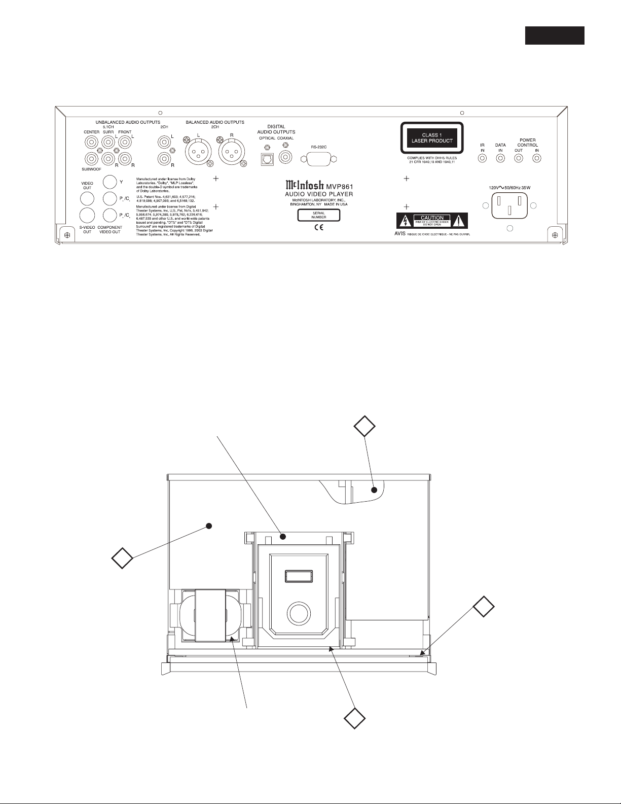
REAR PANEL
MVP861
MAIN
PCB
SECTION LOCATIONS
TOP VIEW WITH COVER REMOVED
VIDEO
PCB
MAIN UNIT
2
CAUTION:
CLASS3R INVISIBLE LASER
RADIATIONWHENOPEN. DO NOT STARE
INTOTHEBEAM OR VIEW DIRECTLY WITH
OPTICALINSTRUMENTS.AVOID DIRECT
EYEEXPOSURE.
4
DISPLAY
5
PCB
TRANSFORMER
4
MECHANISM
PCB
5
Page 6
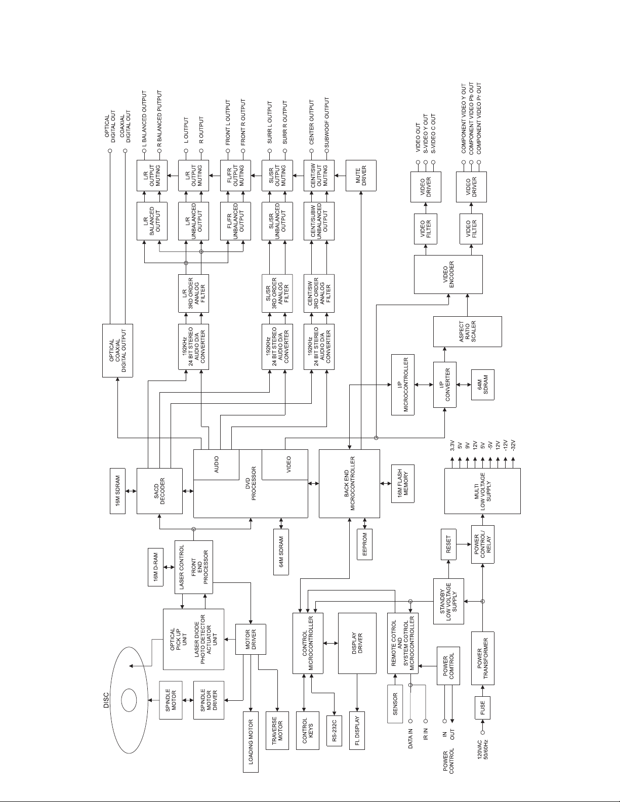
BLOCK DIAGRAM
6
Page 7

INTERCONNECT
MVP861
7 8
Page 8

CY053:1
CY053:2
CY053:3
CY121:3
CY053:4
CY053:5
J1:12
J1:11
CX131:13
CX131:12
CX131:11
CX131:10
CX131:9
CX131:8
CX131:7
CX131:6
CX131:5
CX131:4
CX131:3
CX131:2
CX131:1
2
I5VV=135mA
4
4
4
3
4
4
5
5
3
3
3
3
3
3
3
3
3
3
3
3
3
MAIN 050114 SH 1 OF 3
I5VA=100mA
5V REGULATOR
5VA
5VV
GNDV
GNDV
-12VM
GNDV
-5VV
-32V
GND
NS5V
NC
DGND
NS3.3V
TXD
RXD
DGND
NC
REG4
REG3
REG2
REG1
3.3V
J6:1
J6:2
J6:3
J7:3
J6:4
J6:5
J8:1
J8:2
J9:13
J9:12
J9:11
J9:10
J9:9
J9:8
J9:7
J9:6
J9:5
J9:4
J9:3
J9:2
J9:1
L2
100uH
12
+12VA
I12VA=104mA
HS1
-12VA
I-12VA=179mA
L4
100uH
L5
100uH
C62
47uF
10k
R121
L3
1
C61
.1uF
R124
U14
31
C63
220uF
12V REGULATOR
U15
31
12
C64
220uF
1
C65
220uF
3
U16
12
-12V REGULATOR
C66
1
220uF
12
3
U17
-5V REGULATOR
-32V REGULATOR
Q18
13
D2
R129
2
10k
C67
47uF
2
47.5k
R122
R123
47.5k
R125
47.5k
47.5k
R126
47.5k
47.5k
R128
INOUT
2
INOUT
2
INOUT
INOUT
R127
R131
-36V
C68
C69
.1uF
18V
C70
.1uF
C71
.1uF
2
-18V
C72
.1uF
2
47.5k
47.5k
C75
3300uF
C76
3300uF
D3
D4
220uF
C80
C73
47uF
C77
.1uF
L6
R130
47.5k
12
C78
C74
.1uF
.1uF
47.5k
R132
D5
-23V
C79
.1uF
TO TRANSFORMER PRIMARY
NOT USED
100V AC
0V A
AC L
AC H
J12
J11
J13:6
F1
1A
R139
t
J10:1
J10:2
J10:3
J10:4
J10:5
12
t
12
R140
U21
1
A5VCC
2
B
3
GND
4
C87
.1uF
TXD
RXD
GND
D6
D7
C83
.033uF
D8
D9
K1
54
2
3
16
1.5V
D10
R135
15 OHM
RELAY
3
DRIVER
R137
2K
2
Q19
1
1
A5VCC
2
B
3
GND
Y
U20
R138
10k
C84
220uF
10k
R133
C82
.1uF
U18
161
C1
VCC
15
2
V+
GND
14
3
C1-
T1
OUT
13
4
C2+
R1
.1uF
C81
.1uF
IN
12
5
C2-
R1
OUT
11
6
V-
T1
IN
10
7
T2
T2
IN
9
8
R2
R2
OUT
C86
.1uF
J10:6
C85
.1uF
U19
1
A5VCC
2
B
3
GND
L7
12
R134
3.32k
Y
4
J10:7
J10:8
J10:9
R136
REQUEST
TO SEND
CLEAR
TO SEND
2.21k
100V A
J13:5
Y
RS232
J8:7
ST/ON
120V A
J13:4
IAC=250mA
IAC=250mA
4
JMP1
J8:6
GND
5
J1:6
(IO)
5
J1:7
0V B
20V B
120V B
J13:2
J13:1
J13:3
R274
2.21k
R273
1.5k
26
P0.1
27
P2.6
28
P2.7
1
P2.0
2
P2.1
3
P0.0
4
P1.7
(IO)
1
56.2k
R141
2
J8:8
J8:9
J8:12
GND
GND
REM IN
5
5
J1:4
J1:1
0V A
5
J1:5
T1 VIO
T1 ORN
T1 WHT
120V AC
1
1
1
120V A
100V A
J14:6
J14:4
J14:5
C88
47uF
R142
C89
.1uF
U22
19
21
P0.720P0.622P0.524P0.325P0.2
VDD23P0.4
P1.0
P1.1
P2.5
P2.4
P2.3
P2.2
P1.2
P1.310P1.48XTAL/P3.16RST/P1.55P1.6
XTAL/P3.07VSS
9
11
(IO)
(IO)
C90
.01uF
D11
3
Y1
6.0MHz
T1 BLK
T1 BLU
T1 GRY
1
1
1
0V B
20V B
120V B
J14:2
J14:1
J14:3
10k
10k
10k
R144
R143
18
17
16
15
14
(IO)
13
12
(OD )
J8:10
J8:11
STBY/ON
REM OUT
5
5
J1:2
J1:3
NOT USED
220V AC
0V A
J15:6
R145
0V B
100V A
J15:5
47.5k
1000pF
20V B
120V A
J15:4
R146
120V B
J15:2
J15:3
J15:1
100k
R148
R147
47.5k
4.75M
C91
1uF
C92
C93
.1uF
Ref Des
5VL1125VL3125VL212GND
U5
U6
U7
U8
U9
U10
U11
U12
U13
U26
U28
U36
U37
U38
U39
U41
U42
U43
U44
0V A
100V A
J16:6
J16:5
C95
C94
1000pF
POWER TABLE
5
7
8
5
5
NOT USED
240V AC
120V A
J16:4
.1uF
NS5V
14
16
1
2
3
4
5
6
7
0V B
J16:3
DISCHG
THRS
CTLVOL
RESET
OUTPUT
TRIG
GND
1
2
3
-11.5V
4
4
4
4
4
4
4
4
4
4
4
4
4
4
4
4
4
20V B
J16:2
U23
OUTPUT
C96
.1uF
A5VCC
B
GND
U24
11.5V
8
8
13
8
8
8
8
8
8
13
8
8
8
13
8
8
8
120V B
J16:1
DISCHG
THRS
CTLVOL
RESET
TRIG
Y
T1 GRN
AC14V
J17:1
IAC=1.1-1.3A
2A
U25
C98
.1uF
T1 YEL
1
C100
.033uF
INOUT
2
T1 BLU
1
AC14VCT
J17:2
F3
2A
.1uF
C101
R150
2.74M
C99
1000pF
T1 YEL
1
AC14V
J17:3
IAC=1.1-1.3A
NS5V
R151
C102
AC6V
J17:7
475
1uF
R152
2
T1 GRN
1
R154
2.21k
R153
Q20
1.5k
AC6V
J17:8
3.32k
1
3
15 OHM
R155
6
FIL1
J8:4
R156
475
1
U26:B
J1:9
5
R157
475
3.9V AC
K2
1
2
D12
5V REGULATOR
U27
13
INOUT
2
C103
100uF
R158
5
4
R159
J1:8
5
FIL2
J8:5
3.9V AC
4
3
6.2V
.1uF
C104
U28:B
47.5k
10
Q
9
Q
RXCX
6
Q
7
Q
RXCX
U28:A
R160
2.21k
3.32k
J1:10
5
5VD
.1uF
C110
6.2V
.1uF
C111
.1uF
C112
.1uF
C113
47.5k
.1uF
C114
C115
.1uF
POWER
CONTROL
C109
.1uF
3.3V REGULATOR
U30
4
OUT
IN
2
ENA
ADJ3GND
1
R164
56.2k
5V REGULATOR
U29
2
OUT
IN
1
ENA
ADJ3GND
5
R166
61.9k
8V REGULATOR
U31
4
OUT
IN
2
ENA
ADJ3GND
1
R167
61.9k
12V REGULATOR
U32
4
OUT
IN
2
ENA
ADJ3GND
1
R165
54.9k
L8
12
L9
12
Q21
1
6
2
5
34
R168
D17D18
1k
D19
R169
22.1k
C116
.01uF
DRIVER
R170
562
3.3VA
L13
5
4
5
5
R172
R173
R174
R175
95.3k
187k
332k
475k
D21
R177
1.5k
L10D20
R176
47.5
C117
C118
C119
C120
100pF
100pF
100pF
100pF
100uH
12
C121
220uF
HS2
12
FN2
1
2
3
C122
470uF
HS3
12
FN3
1
2
3
C123
220uF
HS4
12
FN4
1
2
3
C124
220uF
HS5
12
J18
2
IR IN
5
1
J19
2
12
DATAIN
5
1
J7:10
R277
R275
R276
J7:11
100
J7:7
J7:6
J7:4
J7:5
J7:1
806
J7:8
J7:2
806
J7:9
J7:12
3.3V
5VD
5VD
5VD
GND
8V
GND
12V
GND
NS3.3V
NS5V
CY121:103
CY121:73
CY121:63
CY121:43
CY121:53
CY121:13
CY121:83
CY121:23
CY121:93
CY121:123
CY121:113
NS5V
22.1k
R171
2
5V
L11
R178
47.5
L12
R179
47.5
J20
2
1
12
IN
5
1
2
5
1
POWER
CONTROL
J21
OUT
J8:3
R161
47.5
10uF
C106
C218
22000uF
14V
D15
D16
C107
3300uF
D13
D14
C217
4.7uF
475k
R163
R162
12
A
11
B
13
R
15
CX
14
47uF
C108
4
A
5
B
3
R
1
CX
C105
U26:D
U26:A
U26:C
100pF
13
12
3
8
2
11
1
2
9
10
T1 BLK
T1 RED
T1 RED
1
1
1
AC26V
AC26V
AC26VCT
J17:4
J17:5
J17:6
F2
3.3V REGULATOR
13
C97
100uF
14
VDD
13
12
11
10
9
8
47.5k
R149
4
9 10
Page 9

MVP861
2
MAIN 050114 SH 2 OF 3
11 12
Page 10

2
MAIN 050114 SH 3 OF 3
13 14
Page 11

MVP861
2
MAIN 050114
15 16
Page 12

3
4
MECHANISM 320119 and VIDEO 320118
17 18
Page 13

DISPLAY 050115
5
MVP861
19 20
Page 14

MVP861
5
DISPLAY 050115
PARTS LIST
Ref. No.
2
MAIN PCB 050114
C1 CAP MONO 33PF 200V 5%NPO T&R 061307
C2 CAP ELECT 220UF 25V 066507
C3 CAP ELECT 2200UF 25V 20% 066441
C4 CAP MONO 100PF 100V 10% NPO 061300
C5 CAP MONO 100PF 100V 10% NPO 061300
C6 CAP MONO .1uF 50V 20% Z5U 061305
C7 CAP MONO 100PF 100V 10% NPO 061300
C8 CAP MONO .1uF 50V 20% Z5U 061305
C9 CAP MONO 100PF 100V 10% NPO 061300
C1 0 CAP MONO .1uF 50V 20% Z5U 061305
C1 1 CAP MONO .1uF 50V 20% Z5U 061305
C12 CAP ELECT 10UF 16V 066555
C1 3 CAP MONO .1uF 50V 20% Z5U 061305
C14 CAP ELECT 47UF 16V 066380
C15 CAP ELECT 47UF 16V 066380
C16 CAP ELECT 47UF 16V 066380
C17 CAP ELECT 47UF 16V 066380
C18 CAP ELECT 10UF 16V 066555
C19 CAP ELECT 10UF 16V 066555
C2 0 CAP MONO .1uF 50V 20% Z5U 061305
C2 1 CAP MONO .1uF 50V 20% Z5U 061305
C22 CAP MONO 560PF 200V 5% 061308
C23 CAP MONO 560PF 200V 5% 061308
C24 CAP MONO 560PF 200V 5% 061308
C25 CAP MONO 560PF 200V 5% 061308
C26 CAP ELECT 47UF 16V 066380
C27 CAP ELECT 47UF 16V 066380
C28 CAP ELECT 10UF 16V 066555
C2 9 CAP MONO .1uF 50V 20% Z5U 061305
Description Part No.
C30 CAP MONO 100PF 100V 10% NPO 061300
C31 CAP MONO 100PF 100V 10% NPO 061300
C32 CAP MPF 0.0022UF 5% 63VDC 064304
C33 CAP MPF 0.0022UF 5% 63VDC 064304
C34 CAP MPF 0.0022UF 5% 63VDC 064304
C35 CAP MPF 0.0022UF 5% 63VDC 064304
C36 CAP MPF 0.0022UF 5% 63VDC 064304
C37 CAP MPF 0.0022UF 5% 63VDC 064304
C38 CAP MPF 0.0022UF 5% 63VDC 064304
C39 CAP MPF 0.0022UF 5% 63VDC 064304
C40 CAP MONO 220PF 100V 10% NPO 061301
C41 CAP MONO 220PF 100V 10% NPO 061301
C42 CAP MONO 220PF 100V 10% NPO 061301
C43 CAP MONO 220PF 100V 10% NPO 061301
C4 4 CAP PF 0.001UF 5% 63VDC 064300
C4 5 CAP PF 0.001UF 5% 63VDC 064300
C4 6 CAP PF 0.001UF 5% 63VDC 064300
C4 7 CAP PF 0.001UF 5% 63VDC 064300
C4 8 CAP PF 0.001UF 5% 63VDC 064300
C4 9 CAP PF 0.001UF 5% 63VDC 064300
C5 0 CAP PF 0.001UF 5% 63VDC 064300
C5 1 CAP PF 0.001UF 5% 63VDC 064300
C52 CAP ELECT 47UF 16V 066380
C53 CAP ELECT 47UF 16V 066380
C54 CAP ELECT 47UF 16V 066380
C55 CAP ELECT 47UF 16V 066380
C5 6 CAP MONO .1uF 50V 20% Z5U 061305
C5 7 CAP MONO .1uF 50V 20% Z5U 061305
C5 8 CAP MONO .1uF 50V 20% Z5U 061305
C59 CAP ELECT 10UF 50V 066445
C60 CAP ELECT 10UF 50V 066445
C6 1 CAP MONO .1uF 50V 20% Z5U 061305
C62 CAP ELECT 47UF 50V 066215
C63 CAP ELECT 220UF 25V 066507
C64 CAP ELECT 220UF 25V 066507
C65 CAP ELECT 220UF 25V 066507
C66 CAP ELECT 220UF 25V 066507
C67 CAP ELECT 47UF 50V 066215
C68 CAP ELECT 220UF 50V 20% 066254
C6 9 CAP MONO .1uF 50V 20% Z5U 061305
C7 0 CAP MONO .1uF 50V 20% Z5U 061305
C7 1 CAP MONO .1uF 50V 20% Z5U 061305
C7 2 CAP MONO .1uF 50V 20% Z5U 061305
C73 CAP ELECT 47UF 35V 066446
C7 4 CAP MONO .1uF 50V 20% Z5U 061305
C75 CAP ELECT 3300UF 35V 066509
C76 CAP ELECT 3300UF 35V 066509
C7 7 CAP MONO .1uF 50V 20% Z5U 061305
C7 8 CAP MONO .1uF 50V 20% Z5U 061305
C7 9 CAP MONO .1uF 50V 20% Z5U 061305
C8 0 CAP MONO .1uF 50V 20% Z5U 061305
C8 1 CAP MONO .1uF 50V 20% Z5U 061305
C8 2 CAP MONO .1uF 50V 20% Z5U 061305
C83 CAP MPF 0.033UF 100V 10% 064427
C84 CAP ELECT 220UF 50V 20% 066254
C8 5 CAP MONO .1uF 50V 20% Z5U 061305
C8 6 CAP MONO .1uF 50V 20% Z5U 061305
C8 7 CAP MONO .1uF 50V 20% Z5U 061305
C88 CAP ELECT 47UF 35V 066446
C8 9 CAP MONO .1uF 50V 20% Z5U 061305
C9 0 CAP MONO .01UF 50V 20% X7R 061304
C91 CAP MONO 1000PF 50V 10% NPO 061303
21 22
Page 15

MVP861
PARTS LIST con’t
C9 2 CAP MPF 1UF 5% 63VDC 064337
C9 3 CAP MONO .1uF 50V 20% Z5U 061305
C94 CAP MONO 1000PF 50V 10% NPO 061303
C9 5 CAP MONO .1uF 50V 20% Z5U 061305
C9 6 CAP MONO .1uF 50V 20% Z5U 061305
C97 CAP ELECT 100UF 25V 066447
C9 8 CAP MONO .1uF 50V 20% Z5U 061305
C99 CAP MONO 1000PF 50V 10% NPO 061303
C100 CAP MPF 0.033UF 100V 10% 064427
C101 CAP MONO .1uF 50V 20% Z5U 061305
C102 CAP MPF 1UF 5% 63VDC 064337
C103 CAP ELECT 100UF 25V 066447
C104 CAP MONO .1uF 50V 20% Z5U 061305
C105 CAP MONO 100PF 100V 10% NPO 061300
C106 CAP ELECT 22000UF 16V 20% 066552
C107 CAP ELECT 3300UF 35V 066509
C108 CAP ELECT 47UF 35V 066446
C109 CAP MONO .1uF 50V 20% Z5U 061305
C110 CAP MONO .1uF 50V 20% Z5U 061305
C111 CAP MONO .1uF 50V 20% Z5U 061305
C112 CAP MONO .1uF 50V 20% Z5U 061305
C113 CAP MONO .1uF 50V 20% Z5U 061305
C114 CAP MONO .1uF 50V 20% Z5U 061305
C115 CAP MONO .1uF 50V 20% Z5U 061305
C116 CAP MONO .01UF 50V 20% X7R 061304
C117 CAP MONO 100PF 100V 10% NPO 061300
C118 CAP MONO 100PF 100V 10% NPO 061300
C119 CAP MONO 100PF 100V 10% NPO 061300
C120 CAP MONO 100PF 100V 10% NPO 061300
C121 CAP ELECT 220UF 25V 066507
C122 CAP ELECT 470UF 16V 066508
C123 CAP ELECT 220UF 25V 066507
C124 CAP ELECT 220UF 25V 066507
C125 CAP MONO .1uF 50V 20% Z5U 061305
C126 CAP MONO .1uF 50V 20% Z5U 061305
C127 CAP MONO 150pF 200V 5% 061310
C128 CAP MONO .1uF 50V 20% Z5U 061305
C129 CAP ELECT 47UF 35V 066446
C130 CAP MONO .1uF 50V 20% Z5U 061305
C131 CAP ELECT 10UF 16V 066555
C132 CAP MONO .1uF 50V 20% Z5U 061305
C133 CAP ELECT 10UF 50V 066445
C134 CAP MPF 0.1UF 5% 63VDC 064325
C135 CAP ELECT 47UF 35V 066446
C136 CAP ELECT 10UF 16V 066555
C137 CAP ELECT 10UF 16V 066555
C138 CAP MPF 1UF 5% 63VDC 064337
C139 CAP MONO .1uF 50V 20% Z5U 061305
C140 CAP MONO .1uF 50V 20% Z5U 061305
C141 CAP ELECT 47UF 16V 066380
C142 CAP ELECT 47UF 16V 066380
C143 CAP ELECT 10UF 16V 066555
C144 CAP MONO .1uF 50V 20% Z5U 061305
C145 CAP MONO 100PF 100V 10% NPO 061300
C146 CAP MONO 100PF 100V 10% NPO 061300
C147 CAP MPF 0.0022UF 5% 63VDC 064304
C148 CAP MPF 0.0022UF 5% 63VDC 064304
C149 CAP MPF 0.0022UF 5% 63VDC 064304
C150 CAP MPF 0.0022UF 5% 63VDC 064304
C151 CAP MPF 0.0047UF 5% 63VDC 064308
C152 CAP MPF 0.0047UF 5% 63VDC 064308
C153 CAP MPF 0.0047UF 5% 63VDC 064308
C154 CAP MPF 0.0047UF 5% 63VDC 064308
C155 CAP MONO 470PF 100V 10% 061302
C156 CAP MONO 470PF 100V 10% 061302
C157 CAP MONO 470PF 100V 10% 061302
C158 CAP MONO 470PF 100V 10% 061302
C159 CAP ELECT 47UF 16V 066380
C160 CAP ELECT 47UF 16V 066380
C161 CAP MONO .1uF 50V 20% Z5U 061305
C162 CAP MPF 0.0068UF 5% 63VDC 064310
C163 CAP MPF 0.0068UF 5% 63VDC 064310
C164 CAP MONO .1uF 50V 20% Z5U 061305
C165 CAP ELECT 10UF 16V 066555
C166 CAP ELECT 10UF 16V 066555
C167 CAP ELECT 10UF 16V 066555
C168 CAP MONO .1uF 50V 20% Z5U 061305
C169 CAP MONO .1uF 50V 20% Z5U 061305
C170 CAP ELECT 47UF 16V 066380
C171 CAP ELECT 47UF 16V 066380
C172 CAP ELECT 10UF 16V 066555
C173 CAP MONO .1uF 50V 20% Z5U 061305
C174 CAP MONO 100PF 100V 10% NPO 061300
C175 CAP MONO 100PF 100V 10% NPO 061300
C176 CAP MPF 0.0022UF 5% 63VDC 064304
C177 CAP MPF 0.0022UF 5% 63VDC 064304
C178 CAP MPF 0.0022UF 5% 63VDC 064304
C179 CAP MPF 0.0022UF 5% 63VDC 064304
C180 CAP MPF 0.0047UF 5% 63VDC 064308
C181 CAP MPF 0.0047UF 5% 63VDC 064308
C182 CAP MPF 0.015UF 5% 63VDC 064314
C183 CAP MPF 0.015UF 5% 63VDC 064314
C184 CAP MONO 470PF 100V 10% 061302
C185 CAP PF 680PF 5% 160VDC 064298
C186 CAP MONO 470PF 100V 10% 061302
C187 CAP PF 680PF 5% 160VDC 064298
C188 CAP ELECT 47UF 16V 066380
C189 CAP ELECT 47UF 16V 066380
C190 CAP MONO .1uF 50V 20% Z5U 061305
C191 CAP MPF 0.0068UF 5% 63VDC 064310
C192 CAP MPF 0.022UF 5% 63VDC 064316
C193 CAP ELECT 47UF 16V 066380
C194 CAP ELECT 47UF 16V 066380
C195 CAP ELECT 47UF 16V 066380
C196 CAP ELECT 47UF 16V 066380
C197 CAP ELECT 47UF 16V 066380
C198 CAP ELECT 47UF 16V 066380
C199 CAP ELECT 47UF 16V 066380
C200 CAP ELECT 47UF 16V 066380
C201 CAP ELECT 47UF 16V 066380
C202 CAP ELECT 47UF 16V 066380
C203 CAP ELECT 47UF 16V 066380
C204 CAP ELECT 47UF 16V 066380
C205 CAP ELECT 220UF 25V 066507
C206 CAP ELECT 220UF 25V 066507
C207 CAP ELECT 220UF 25V 066507
C208 CAP ELECT 220UF 25V 066507
C209 CAP ELECT 220UF 25V 066507
C210 CAP ELECT 220UF 25V 066507
C211 CAP ELECT 220UF 25V 066507
C212 CAP ELECT 220UF 25V 066507
C213 CAP ELECT 220UF 25V 066507
C214 CAP ELECT 220UF 25V 066507
C215 CAP ELECT 220UF 25V 066507
C216 CAP ELECT 220UF 25V 066507
C217 CAP ELECT 4.7UF 50V 066512
C218 CAP ELECT 10UF 50V 066445
D1 DIODE RECTIFIER 070131
D2 DIODE ZENER 33V 5% 1/2W 070121
D3 DIODE SENER 6.2V 5% 500MW 070085
D4 DIODE RECTIFIER 070131
D5 DIODE RECTIFIER 070131
D6 DIODE RECTIFIER 070131
D7 DIODE RECTIFIER 070131
D8 DIODE RECTIFIER 070131
D9 DIODE RECTIFIER 070131
D1 0 DIODE SILICON 070047
D1 1 DIODE SILICON 070047
D1 2 DIODE SILICON 070047
D1 3 SCHOTTKY RECTIFIER 5A 100V 070171
D1 4 SCHOTTKY RECTIFIER 5A 100V 070171
D1 5 SCHOTTKY RECTIFIER 5A 100V 070171
D1 6 SCHOTTKY RECTIFIER 5A 100V 070171
D1 7 DIODE SILICON 070047
D1 8 DIODE SILICON 070047
D1 9 DIODE SILICON 070047
D2 0 DIODE SILICON 070047
D2 1 DIODE SILICON 070047
F1 FUSE 1A 250V SB 5X20 ULCSA IEC 089107
F2 FUSE 2A 250V SLO-BLO 5X20 IEC 089088
F3 FUSE 2A 250V SLO-BLO 5X20 IEC 089088
FN1 FILTER EMI 180057
FN2 FILTER EMI 180057
FN3 FILTER EMI 180057
FN4 FILTER EMI 180057
FN5 FILTER EMI 180057
FN6 FILTER EMI 180057
FN7 FILTER EMI 180057
HS1 HEATSINK TO-220 080017
HS2 HEATSINK TO220 080019
HS3 HEATSINK TO-220 080017
HS4 HEATSINK TO220 080019
HS5 HEATSINK TO220 080019
J1 FFC CONNECTOR 27PIN 117854
J2 RECEPTACLE XLR MALE 117686
J3 RECEPTACLE XLR MALE 117686
J4 JACK RCA 1X2 WHT/RED 14MM 117788
J5 JACK RCA 3X2 WHT/RED 14MM 117790
J6 SHROUDED HEADER 5 PIN 117852
J7 12 PIN SHROUDED HEADER 117796
J8 CONN 12 PIN FFC 117720
J9 CONN 13 PIN FFC 117861
J1 0 CONN SUB-D 9 PIN 117507
J11 BLADE FASTON W/FEET 117708
J12 BLADE FASTON W/FEET 117708
J13 CONN PCB MOUNT POWER RED 117719
J14 CONN PCB MOUNT POWER RED 117719
J15 CONN PCB MOUNT POWER RED 117719
J16 CONN PCB MOUNT POWER RED 117719
J17 HEADER 8 PIN MTA-156 117717
J18 JACK HEADPHONE STEREO 1/8IN 117759
J19 JACK HEADPHONE STEREO 1/8IN 117759
J20 JACK HEADPHONE STEREO 1/8IN 117759
J21 JACK HEADPHONE STEREO 1/8IN 117759
J2 2 JACK RCA ORANGE WITH GOLD 117798
K1 RELAY 5V DPST 087074
K2 RELAY REED FORM 1A 5V 500 OHMS 087050
L1 CHOKE 18UH 5%-10% 122224
L2 INDUCTOR 100UH POWER 122312
L 3 BEADS FERRITE LEADED 076019
L4 INDUCTOR 100UH POWER 122312
L5 INDUCTOR 100UH POWER 122312
L 6 BEADS FERRITE LEADED 076019
L 7 BEADS FERRITE LEADED 076019
L 8 BEADS FERRITE LEADED 076019
L 9 BEADS FERRITE LEADED 076019
L1 0 FERRITE 076019
L1 1 FERRITE 076019
L1 2 FERRITE 076019
L1 3 INDUCTOR 100UH POWER 122312
L1 4 CHOKE 18UH 5%-10% 122224
L1 5 CHOKE 18UH 5%-10% 122224
L1 6 CHOKE 18UH 5%-10% 122224
OPT1 TRANSMITTER FIBER OPTIC 058157
Q1 TRANSISTOR PNP 132224
Q2 TRANSISTOR SI NPN 25V 132257
Q3 TRANSISTOR SI NPN 25V 132257
Q4 TRANSISTOR SI NPN 25V 132257
23 24
Page 16

PARTS LIST con’t
Q5 TRANSISTOR SI NPN 25V 132257
Q6 TRANSISTOR SI NPN 25V 132257
Q7 TRANSISTOR SI NPN 25V 132257
Q8 TRANSISTOR SI NPN 25V 132257
Q9 TRANSISTOR SI NPN 25V 132257
Q1 0 TRANSISTOR SI NPN 25V 132257
Q1 1 TRANSISTOR SI NPN 25V 132257
Q1 2 TRANSISTOR SI NPN 25V 132257
Q1 3 TRANSISTOR SI NPN 25V 132257
Q1 4 TRANSISTOR SI NPN 25V 132257
Q1 5 TRANSISTOR SI NPN 25V 132257
Q1 6 TRANSISTOR SI NPN 25V 132257
Q1 7 TRANSISTOR SI NPN 25V 132257
Q1 8 TRANSISTOR PNP SILICON 132172
Q1 9 TRANSISTOR NPN SILICON 132171
Q2 0 TRANSISTOR PNP 132263
Q21 COUPLER OPTICAL SCHMITT OUTPUT 131023
Q2 2 TRANSISTOR SI NPN 25V 132257
Q2 3 TRANSISTOR SI NPN 25V 132257
Q2 4 TRANSISTOR SI NPN 25V 132257
Q2 5 TRANSISTOR SI NPN 25V 132257
Q2 6 TRANSISTOR SI NPN 25V 132257
Q2 7 TRANSISTOR SI NPN 25V 132257
Q2 8 TRANSISTOR SI NPN 25V 132257
Q2 9 TRANSISTOR SI NPN 25V 132257
R1 RES MF 150 OHM 1% 1/4W 144122
R2 RES MF 10K 1% 1/4W 144053
R3 RES MF 47.5K 1% 1/4W 144108
R4 RES MF 47.5K 1% 1/4W 144108
R5 RES MF 100 OHM 1% 1/4W 144196
R6 RES MF 100 OHM 1% 1/4W 144196
R7 RES MF 100 OHM 1% 1/4W 144196
R8 RES MF 100 OHM 1% 1/4W 144196
R9 RES MF 10K 1% 1/4W 144053
R1 0 RES MF 47.5K 1% 1/4W 144108
R1 1 RES MF 47.5K 1% 1/4W 144108
R1 2 RES MF 47.5 OHM 1% 1/4W 144442
R1 3 RES MF 10K 1% 1/4W 144053
R1 4 RES MF 47.5K 1% 1/4W 144108
R1 5 RES MF 47.5K 1% 1/4W 144108
R1 6 RES MF 47.5K 1% 1/4W 144108
R1 7 RES MF 47.5K 1% 1/4W 144108
R1 8 RES MF 47.5 OHM 1% 1/4W 144442
R1 9 RES MF 47.5 OHM 1% 1/4W 144442
R2 0 RES MF 47.5 OHM 1% 1/4W 144442
R2 1 RES MF 47.5 OHM 1% 1/4W 144442
R2 2 RES MF 47.5K 1% 1/4W 144108
R2 3 RES MF 47.5 OHM 1% 1/4W 144442
R2 4 RES MF 47.5 OHM 1% 1/4W 144442
R2 5 RES MF 47.5 OHM 1% 1/4W 144442
R2 6 RES MF 47.5 OHM 1% 1/4W 144442
R2 7 RES MF 10K 1% 1/4W 144053
R2 8 RES MF 47.5K 1% 1/4W 144108
R2 9 RES MF 6.49K .5% 1/4W 144401
R3 0 RES MF 6.49K .5% 1/4W 144401
R3 1 RES MF 6.49K .5% 1/4W 144401
R3 2 RES MF 6.49K .5% 1/4W 144401
R3 3 RES MF 6.49K .5% 1/4W 144401
R3 4 RES MF 6.49K .5% 1/4W 144401
R3 5 RES MF 6.49K .5% 1/4W 144401
R3 6 RES MF 6.49K .5% 1/4W 144401
R3 7 RES MF 100 OHM 1% 1/4W 144196
R3 8 RES MF 100 OHM 1% 1/4W 144196
R3 9 RES MF 100 OHM 1% 1/4W 144196
R4 0 RES MF 100 OHM 1% 1/4W 144196
R4 1 RES MF 1K 1% 1/4W 144090
R4 2 RES MF 150 OHM 1% 1/4W 144122
R4 3 RES MF 150 OHM 1% 1/4W 144122
R4 4 RES MF 150 OHM 1% 1/4W 144122
R4 5 RES MF 150 OHM 1% 1/4W 144122
R4 6 RES MF 332 OHM 1% 1/4W 144446
R4 7 RES MF 332 OHM 1% 1/4W 144446
R4 8 RES MF 332 OHM 1% 1/4W 144446
R4 9 RES MF 332 OHM 1% 1/4W 144446
R5 0 RES MF 47.5K 1% 1/4W 144108
R5 1 RES MF 47.5K 1% 1/4W 144108
R5 2 RES MF 47.5K 1% 1/4W 144108
R5 3 RES MF 47.5K 1% 1/4W 144108
R5 4 RES MF 10K 1% 1/4W 144053
R5 5 RES MF 2.94K 1% 1/4W 144495
R5 6 RES MF 2.94K 1% 1/4W 144495
R5 7 RES MF 2.94K 1% 1/4W 144495
R5 8 RES MF 2.94K 1% 1/4W 144495
R5 9 RES MF 365 OHM 1/4W 144071
R6 0 RES MF 182 OHM 1/4W 1% 144273
R6 1 RES MF 365 OHM 1/4W 144071
R6 2 RES MF 182 OHM 1/4W 1% 144273
R6 3 RES MF 182 OHM 1/4W 1% 144273
R6 4 RES MF 365 OHM 1/4W 144071
R6 5 RES MF 182 OHM 1/4W 1% 144273
R6 6 RES MF 365 OHM 1/4W 144071
R6 7 RES MF 2.1K 1% 1/4W 144299
R6 8 RES MF 2.1K 1% 1/4W 144299
R6 9 RES MF 2.1K 1% 1/4W 144299
R7 0 RES MF 2.1K 1% 1/4W 144299
R7 1 RES MF 2.67K 1% 1/4W 144121
R7 2 RES MF 2.67K 1% 1/4W 144121
R7 3 RES MF 2.67K 1% 1/4W 144121
R7 4 RES MF 2.67K 1% 1/4W 144121
R7 5 RES MF 2.1K 1% 1/4W 144299
R7 6 RES MF 2.1K 1% 1/4W 144299
R7 7 RES MF 2.1K 1% 1/4W 144299
R7 8 RES MF 2.1K 1% 1/4W 144299
R7 9 RES MF 3.32K 1% 1/4W 144095
R8 0 RES MF 3.32K 1% 1/4W 144095
R8 1 RES MF 3.32K 1% 1/4W 144095
R8 2 RES MF 3.32K 1% 1/4W 144095
R8 3 RES MF 3.32K 1% 1/4W 144095
R8 4 RES MF 3.32K 1% 1/4W 144095
R8 5 RES MF 3.32K 1% 1/4W 144095
R8 6 RES MF 3.32K 1% 1/4W 144095
R8 7 RES MF 1.65K 1% 1/4W 144093
R8 8 RES MF 1.65K 1% 1/4W 144093
R8 9 RES MF 1.65K 1% 1/4W 144093
R9 0 RES MF 1.65K 1% 1/4W 144093
R9 1 RES MF 1.65K 1% 1/4W 144093
R9 2 RES MF 1.65K 1% 1/4W 144093
R9 3 RES MF 1.65K 1% 1/4W 144093
R9 4 RES MF 1.65K 1% 1/4W 144093
R9 5 RES MF 47.5K 1% 1/4W 144108
R9 6 RES MF 47.5K 1% 1/4W 144108
R9 7 RES MF 47.5K 1% 1/4W 144108
R9 8 RES MF 47.5K 1% 1/4W 144108
R9 9 RES MF 332 OHM 1% 1/4W 144446
R100 RES MF 332 OHM 1% 1/4W 144446
R101 RES MF 332 OHM 1% 1/4W 144446
R102 RES MF 332 OHM 1% 1/4W 144446
R103 RES MF 5.62OHM 1/4W 144168
R104 RES MF 5.62OHM 1/4W 144168
R105 RES MF 150 OHM 1% 1/4W 144122
R106 RES MF 150 OHM 1% 1/4W 144122
R107 RES MF 150 OHM 1% 1/4W 144122
R108 RES MF 150 OHM 1% 1/4W 144122
R109 RES MF 6.49K .5% 1/4W 144401
R110 RES MF 6.49K .5% 1/4W 144401
R111 RES MF 6.49K .5% 1/4W 144401
R112 RES MF 6.49K .5% 1/4W 144401
R113 RES MF 100 OHM 1% 1/4W 144196
R114 RES MF 6.49K .5% 1/4W 144401
R115 RES MF 100 OHM 1% 1/4W 144196
R116 RES MF 6.49K .5% 1/4W 144401
R117 RES MF 100 OHM 1% 1/4W 144196
R118 RES MF 6.49K .5% 1/4W 144401
R119 RES MF 100 OHM 1% 1/4W 144196
R120 RES MF 6.49K .5% 1/4W 144401
R121 RES MF 10K 1% 1/4W 144053
R122 RES MF 47.5K 1% 1/4W 144108
R123 RES MF 47.5K 1% 1/4W 144108
R124 RES MF 47.5K 1% 1/4W 144108
R125 RES MF 47.5K 1% 1/4W 144108
R126 RES MF 47.5K 1% 1/4W 144108
R127 RES MF 47.5K 1% 1/4W 144108
R128 RES MF 47.5K 1% 1/4W 144108
R129 RES MF 10K 1% 1/4W 144053
R130 RES MF 47.5K 1% 1/4W 144108
R131 RES MF 47.5K 1% 1/4W 144108
R132 RES MF 47.5K 1% 1/4W 144108
R133 RES MF 10K 1% 1/4W 144053
R134 RES MF 3.32K 1% 1/4W 144095
R135 RN 1/2 T1 15 OHM 1% 144161
R136 RES MF 2.21K 1% 1/4W 144298
R137 RES MF 2K 1/4W 144094
R138 RES MF 10K 1% 1/4W 144053
R139 PTC RESETTABLE FUSE 144488
R140 PTC RESETTABLE FUSE 144488
R141 RES MF 56.2K 1% 1/4W 144402
R142 RES MF 10K 1% 1/4W 144053
R143 RES MF 10K 1% 1/4W 144053
R144 RES MF 10K 1% 1/4W 144053
R145 RES MF 47.5K 1% 1/4W 144108
R146 RES MF 47.5K 1% 1/4W 144108
R147 RES MF 4.75M 1% 1/4W 144379
R148 RES MF 100K 1% 1/4W 144113
R149 RES MF 47.5K 1% 1/4W 144108
R150 RES MF 2.74M 1/4W 144271
R151 RES MF 475 OHM 1% 1/4W 144086
R152 RES MF 2.21K 1% 1/4W 144298
R153 RES MF 3.32K 1% 1/4W 144095
R154 RES MF 1.5K 1% 1/4W 144128
R155 RES MF 475 OHM 1% 1/4W 144086
R156 RN 1/2 T1 15 OHM 1% 144161
R157 RES MF 475 OHM 1% 1/4W 144086
R158 RES MF 47.5K 1% 1/4W 144108
R159 RES MF 3.32K 1% 1/4W 144095
R160 RES MF 2.21K 1% 1/4W 144298
R161 RES MF 47.5 OHM 1% 1/4W 144442
R162 RES MF 475K 1% 1/4W 144364
R163 RES MF 47.5K 1% 1/4W 144108
R164 RES MF 56.2K 1% 1/4W 144402
R165 RES MF 54.9K 1% 1/4W 144139
R166 RES MF 61.9K OHM 1/4W 144335
R167 RES MF 61.9K OHM 1/4W 144335
R168 RES MF 1K 1% 1/4W 144090
R169 RES MF 22.1K 1% 1/4W 144187
R170 RES MF 562 OHM 1% 1/4W 144408
R171 RES MF 22.1K 1% 1/4W 144187
R172 RES MF 95.3K 1% 1/4W 144127
R173 RES MF 187K 1% 1/4W 144406
R174 RES MF 332K 1% 1/4W 144119
R175 RES MF 475K 1% 1/4W 144364
R176 RES MF 47.5 OHM 1% 1/4W 144442
R177 RES MF 1.5K 1% 1/4W 144128
R178 RES MF 47.5 OHM 1% 1/4W 144442
R179 RES MF 47.5 OHM 1% 1/4W 144442
R180 RES MF 100 OHM 1% 1/4W 144196
R181 RES MF 332 OHM 1/4W 1% 144446
R182 RES MF 47.5K 1% 1/4W 144108
R183 RES MF 10K 1% 1/4W 144053
25 26
Page 17

MVP861
PARTS LIST con’t
R184 RES MF 365 OHM 1/4W 1% 144071
R185 RES MF 365 OHM 1/4W 1% 144071
R186 RES MF 182 OHM 1/4W 1% 144273
R187 RES MF 365 OHM 1/4W 1% 144071
R188 RES MF 182 OHM 1/4W 1% 144273
R189 RES MF 182 OHM 1/4W 1% 144273
R190 RES MF 365 OHM 1/4W 1% 144071
R191 RES MF 182 OHM 1/4W 1% 144273
R192 RES MF 365 OHM 1/4W 1% 144071
R193 RES MF 2.67K 1% 1/4W 144121
R194 RES MF 2.67K 1% 1/4W 144121
R195 RES MF 2.67K 1% 1/4W 144121
R196 RES MF 2.67K 1% 1/4W 144121
R197 RES MF 1.33K 1/4W 1% 144403
R198 RES MF 1.33K 1/4W 1% 144403
R199 RES MF 3920 OHM 1% 1/4W 144198
R200 RES MF 3920 OHM 1% 1/4W 144198
R201 RES MF 3920 OHM 1% 1/4W 144198
R202 RES MF 3920 OHM 1% 1/4W 144198
R203 RES MF 1.33K 1/4W 1% 144403
R204 RES MF 1.33K 1/4W 1% 144403
R205 RES MF 47.5K 1% 1/4W 144108
R206 RES MF 47.5K 1% 1/4W 144108
R207 RES MF 332 OHM 1% 1/4W 144446
R208 RES MF 332 OHM 1% 1/4W 144446
R209 RES MF 150 OHM 1% 1/4W 144122
R210 RES MF 150 OHM 1% 1/4W 144122
R211 RES MF 6.49K .5% 1/4W 144401
R212 RES MF 6.49K .5% 1/4W 144401
R213 RES MF 100 OHM 1% 1/4W 144196
R214 RES MF 6.49K .5% 1/4W 144401
R215 RES MF 100 OHM 1% 1/4W 144196
R216 RES MF 6.49K .5% 1/4W 144401
R217 RES MF 10K 1% 1/4W 144053
R218 RES MF 365 OHM 1/4W 144071
R219 RES MF 182 OHM 1/4W 1% 144273
R220 RES MF 365 OHM 1/4W 144071
R221 RES MF 182 OHM 1/4W 1% 144273
R222 RES MF 182 OHM 1/4W 1% 144273
R223 RES MF 365 OHM 1/4W 1% 144071
R224 RES MF 182 OHM 1/4W 1% 144273
R225 RES MF 365 OHM 1/4W 1% 144071
R226 RES MF 2.67K 1% 1/4W 144121
R227 RES MF 2.67K 1% 1/4W 144121
R228 RES MF 1.82K 1% 1/4W 144296
R229 RES MF 1.82K 1% 1/4W 144296
R230 RES MF 1.33K 1/4W 1% 144403
R231 RES 1.37K 1% 1/4W 144092
R232 RES MF 3920 OHM 1% 1/4W 144198
R233 RES MF 3920 OHM 1% 1/4W 144198
R234 RES MF 8.06K 1% 1/4W 144100
R235 RES MF 8.06K 1% 1/4W 144100
R236 RES MF 1.33K 1/4W 1% 144403
R237 RES 1.37K 1% 1/4W 144092
R238 RES MF 47.5K 1% 1/4W 144108
R239 RES MF 47.5K 1% 1/4W 144108
R240 RES MF 332 OHM 1% 1/4W 144446
R241 RES MF 332 OHM 1% 1/4W 144446
R242 RES MF 150 OHM 1% 1/4W 144122
R243 RES MF 150 OHM 1% 1/4W 144122
R244 RES MF 6.49K .5% 1/4W 144401
R245 RES MF 6.49K .5% 1/4W 144401
R246 RES MF 100 OHM 1% 1/4W 144196
R247 RES MF 6.49K .5% 1/4W 144401
R248 RES MF 100 OHM 1% 1/4W 144196
R249 RES MF 6.49K .5% 1/4W 144401
R250 RES MF 3.48K OHM 1/4W 1% 144448
R251 RES MF 365 OHM 1/4W 1% 144071
R252 RES MF 3.48K OHM 1/4W 1% 144448
R253 RES MF 365 OHM 1/4W 1% 144071
R254 RES MF 3.48K OHM 1/4W 1% 144448
R255 RES MF 365 OHM 1/4W 1% 144071
R256 RES MF 3.48K OHM 1/4W 1% 144448
R257 RES MF 365 OHM 1/4W 1% 144071
R258 RES MF 3.48K OHM 1/4W 1% 144448
R259 RES MF 365 OHM 1/4W 1% 144071
R260 RES MF 3.48K OHM 1/4W 1% 144448
R261 RES MF 365 OHM 1/4W 1% 144071
R262 RES MF 3.48K OHM 1/4W 1% 144448
R263 RES MF 365 OHM 1/4W 1% 144071
R264 RES MF 3.48K OHM 1/4W 1% 144448
R265 RES MF 365 OHM 1/4W 1% 144071
R266 RES MF 3.48K OHM 1/4W 1% 144448
R267 RES MF 365 OHM 1/4W 1% 144071
R268 RES MF 3.48K OHM 1/4W 1% 144448
R269 RES MF 365 OHM 1/4W 1% 144071
R270 RES MF 3.48K OHM 1/4W 1% 144448
R271 RES MF 365 OHM 1/4W 1% 144071
R272 RES MF 3.48K OHM 1/4W 1% 144448
R273 RES MF 1.5K 1% 1/4W 144128
R274 RES MF 2.21K 1% 1/4W 144298
R275 RES MF 806 OHM 1% 1/4W 144089
R276 RES MF 806 OHM 1% 1/4W 144089
R277 RES MF 100 OHM 1% 1/4W 144196
T 1 TRANSFORMER DIGITAL INTERFACE 159285
U1 SINGLE 2-INPUT AND GATE 133502
U2 SINGLE 2-INPUT NAND GATE 133501
U3 SINGLE 2-INPUT OR GATE 133516
U4 D/A CONVERTER 192KHZ 24 BIT 133441
U5 IC DUAL OPERATIONAL AMPLIFIER 133260
U6 IC DUAL OPERATIONAL AMPLIFIER 133260
U7 IC SPST QUAD FET SWITCHES N O 133426
U8 IC OP AMP DUAL FET INPUT 133432
U9 IC OP AMP DUAL FET INPUT 133432
U1 0 IC DUAL OPERATIONAL AMPLIFIER 133260
U1 1 IC DUAL OPERATIONAL AMPLIFIER 133260
U1 2 IC DUAL OPERATIONAL AMPLIFIER 133260
U1 3 IC DUAL OPERATIONAL AMPLIFIER 133260
U1 4 IC REGULATOR 5V 133250
U15 IC REGULATOR 12V 133156
U1 6 IC REGULATOR -12V 133155
U1 7 IC -5V REGULATOR 133253
U1 8 IC RS232 LINE DRIVER 133380
U1 9 SINGLE 2-INPUT OR GATE 133516
U2 0 SINGLE 2-INPUT OR GATE 133516
U2 1 SINGLE 2-INPUT NAND GATE 133501
U2 2 PROGRAMMED VERSION OF 133495 133533
U2 3 IC TIMER 133212
U2 4 SINGLE 2-INPUT OR GATE 133516
U2 5 REGULATOR 3.3V LOW DROP 133464
U2 6 IC AND 2 INPUT X 4 133175
U2 7 REGULATOR 5V LOW DROP 133452
U2 8 IC MONOSTB MULTIVIB X 2 133182
U2 9 IC REGULATOR LOW DROPOUT ADJ 133531
U3 0 IC REGULATOR 1.25A LOW DROPOUT 133431
U3 1 IC REGULATOR 1.25A LOW DROPOUT 133431
U3 2 IC REGULATOR 1.25A LOW DROPOUT 133431
U3 3 D/A CONVERTER 192KHZ 24 BIT 133441
U3 4 SINGLE 2-INPUT OR GATE 133516
U3 5 SINGLE 2-INPUT OR GATE 133516
U3 6 IC SPST QUAD FET SWITCHES N O 133426
U3 7 IC OP AMP DUAL FET INPUT 133432
U3 8 IC OP AMP DUAL FET INPUT 133432
U3 9 IC DUAL OPERATIONAL AMPLIFIER 133260
U4 0 D/A CONVERTER 192KHZ 24 BIT 133441
U4 1 IC SPST QUAD FET SWITCHES N O 133426
U4 2 IC OP AMP DUAL FET INPUT 133432
U4 3 IC OP AMP DUAL FET INPUT 133432
U4 4 IC DUAL OPERATIONAL AMPLIFIER 133260
Y1 RESONATOR CERAMIC 6.0MHZ W/CAP 180039
3
DISPLAY PCB 050115
C1 CAP ELECT 10UF 16V 066382
C2 CAP ELECT 47UF 16V 066380
C3 CAP ELECT 10UF 50V LOW ESR 066437
C4 CAP MONO 1000PF 50V 10% NPO 061303
C5 CAP ELECT 47UF 16V 066380
C6 CAP MONO .1uF 50V 20% Z5U 061305
C7 CAP MONO .1uF 50V 20% Z5U 061305
C8 CAP MONO .1uF 50V 20% Z5U 061305
C9 CAP MONO .1uF 50V 20% Z5U 061305
C1 0 CAP ELECT 47UF 16V 6.3X5 CASE 066380
DS1 LED GRN 5MM HI-INTENSITY 058165
DS2 LED GRN 5MM HI-INTENSITY 058165
DS3 LED GRN 5MM HI-INTENSITY 058165
DS4 LED SQUARE RED 058109
DS5 VACUUM FLUORESCENT DISPLAY 310346
DS6 LED SQUARE RED 058109
J1 CONN 12 PIN FFC 117720
J2 FFC CONNECTOR 17PIN 117853
J3 BLADE FASTON W/FEET 117708
L 1 CHOKE 18uH 5%-10% 122224
M T 1 SENSOR IR 38KHZ 121046
Q1 TRANSISTOR NPN 132223
R1 RES MF 100 OHM 1% 1/4W 144196
R2 RES MF 100 OHM 1% 1/4W 144196
R3 RES MF 100 OHM 1% 1/4W 144196
R4 RES MF 332 OHM 1% 1/4W 144446
R5 RES MF 10 OHM 10% 1/4W 144157
R6 RES MF 10K 1% 1/4W 144053
R7 RES MF 332 OHM 1% 1/4W 144446
R8 RES MF 8.25K 1% 1/4W 144153
R9 RES MF 47.5K 1% 1/4W 144108
R1 0 RES MF 47.5K 1% 1/4W 144108
R1 1 RES MF 47.5K 1% 1/4W 144108
R1 2 RES MF 1K 1% 1/4W 144090
R1 3 RES MF 1K 1% 1/4W 144090
R1 4 RES MF 1K 1% 1/4W 144090
R1 5 RES MF 4.22K 1% 1/4W 144476
R1 6 RES MF 150 OHM 1% 1/4W 144122
R1 7 RES MF 150 OHM 1% 1/4W 144122
R1 8 RES MF 150 OHM 1% 1/4W 144122
R1 9 RES MF 182 OHM 1/4W 1% 144273
R2 0 RES MF 182 OHM 1% 1/4W 144273
R2 1 RES MF 267 OHM 1% 1/4W 144173
S1 SWITCH PB TACT 150058
S2 SWITCH PB TACT 150058
S3 SWITCH PB TACT 150058
S4 SWITCH PB TACT 150058
S5 SWITCH PB TACT 150058
S6 SWITCH PB TACT 150058
S7 SWITCH PB TACT 150058
S8 SWITCH PB TACT 150058
S9 SWITCH PB TACT 150058
S10 SWITCH PB TACT 150058
U1 5X7 DOT CHARACTER DISPLAY DRIVER 310345
Y1 CERAMIC RESONATOR 180038
27 28
Page 18

EXPLODED VIEW AND PARTS LIST
(9X)
50
(4X)
(4X)
14
11
7
32
12
(3X)
6
30
1
3
5
13
4
8
10
12
2
11
14
(4X)
(3X)
31
29
33
(6X)
(10X)
9
1
32
(4X)
(4X)
22
37
54
38
(2X)
43
49
40
25
28
48
24
35
(2X)
42
51
40
(2X)
19
18
27
20
17
16
(2X)
46
28
21
23
(7X)
15
40
59
(4X)
56
DISPLAY PCB ASSY
REF
(4X)
58
(2X)
42
57
34
39
22
REF
REF
40
FRONT PANEL ASSY
REF
42
(9X)
53
48
REF
39
39
39
39
40
(2X)
45
(18X)
(2X)
47
41
39
(4X)
26
(4X)
44
(4X)
36
Ref. No.
Part No.
Description
1 005090 BRACKET EXTRUSION
2 016513 GLASS MVP861
3 017517 PUSHBUTTON ASSY
4 017531 PUSHBUTTON ASSY RED
5 017781 BEZEL FRONT
6 017906 FAB GUIDE PCB
7 018585 EXTRUSION MA TERIAL, GLASS
8 018706 EXTRUSION BOTTOM
9 078033 O-RING
10 092445 DISPLAY FIL TER
11 094016 TAPE FOAM 1/4 X 1/8 IN
12 094360 TAPE FOAM 1/2 X 1/2 IN
13 098113 CORD DIAL .027 BLK BRAID SLK
14 100147 SCREW MACH 6-32 X 3/16 PHIL
15 005448 FAB REAR PANEL
16 102001 NUT KEP 4-40 ZINC PLA TE
17 102020 NUT MACH 6-32 SELF-LOCK
18 117755 RECEPTACLE INPUT & LINE FIL TER
52
40
19 005444 TRA Y
20 005445 FAB BRACKET LEFT
21 005446 FAB BRACKET RIGHT
22 005447 FAB SUBP ANEL
23 005449 FAB SIDE RIGHT
24 005450 FAB SIDE LEFT
25 005451 FAB BRACKET TRANSFORMER
26 017218 FOOT PLASTIC BLACK
27 017452 KLIP WIRE
28 017687 CLAMP CABLE
29 050115 ASSY PCB DISPLA Y
30 017901 LOGO PUSHBUTTON BACKLIGHT
31 017902 SUPPORT PCB LOCKING ADHSV BASE
32 017907 TITLE/PUSHBUTTON BACKLIGHT
33 017933 CIRCUIT BOARD SUPPORT
34 017963 MOLD DOOR MVP861
35 019056 SPRING
36 100159 SCREW MACH 10-32 X 3/4 PH PN BLK
55
37 100296 SCREW MACH SEM 4-40 X 5/16 PH PN
38 100300 SCREW MACH SEMS 6-32 X 1 PH P AN
39 101054 SCREW T APTT 6-32 X 1/4 PH PN BLK
40 101196 SCREW TA P SEMS 6-32 X 1/4 PH P AN
41 101197 SCREW HI/L0 4-24 X 3/8 PH RD BLK
42 101222 SCREW TT SEMS 6-32 X 1/4 PH P AN
43 102003 NUT MACH 6-32 W/LOCK
44 104083 WASHER #10 PLATED 10406200
45 104142 WASHER LOCK 2.5mm INT STR ZINC
46 104145 WASHER NYLON BLK
47 112015 STAND-OFF
48 117800 MTA CONNECTOR 8PIN .156
49 159343 TRANSFORMER R-CORE POWER
50 166034 LABEL INTERNAL LASER W ARNING
51 320176 MAIN UNIT
52 320177 VIDEO UNIT
53 050114 ASSY PCB MAIN
54 320178 DVD MECHANISM ASSY DVD-2900
29 30
Page 19

REPACKING INSTRUCTIONS
MVP861
31
Page 20

DVD AUDIO/VIDEO PLAYER
SERVICE MANUAL
The continuous improvement of its products is the policy of McIntosh Laboratory Incorporated, who reserve the right to improve design without
notice. Because of the constant upgrading of McIntosh products’ circuitry and components, the Company cannot insure, and does not warrant, the
accuracy of the within schematic material, which is intended for information only.
McINTOSH LABORATORY, INC., 2 CHAMBERS STREET, BINGHAMTON, NEW YORK 13903 Printed in U.S.A. Part Number 040968
 Loading...