


Makita JS3200 Manual
I N S T R U C T I O N M A N U A L
M A N U E L D ' I N S T R U C T I O N
M A N U A L D E I N S T R U C C I O N E S
Shear
Cisaille
Cizalla
JS3200
004667
DOUBLE INSULATION DOUBLE ISOLATION
DOBLE AISLAMIENTO
 WARNING:
For your personal safety, READ and UNDERSTAND before using. SAVE THESE INSTRUCTIONS FOR FUTURE REFERENCE.
 AVERTISSEMENT:
Pour votre propre sécurité, prière de lire attentivement avant l’utilisation. GARDER CES INSTRUCTIONS POUR RÉFÉRENCE ULTÉRIEURE.
 ADVERTENCIA:
Para su seguridad personal, LEA DETENIDAMENTE este manual antes de usar la herramienta. GUARDE ESTAS INSTRUCCIONES PARA FUTURA REFERENCIA.

ENGLISH
SPECIFICATIONS
Model |
JS3200 |
||
|
|
|
|
|
Steel up to 400 N/mm2 |
3.2 mm (10 ga.) |
|
Max. cutting capacities |
Steel up to 600 N/mm2 |
2.5 mm (13 ga.) |
|
Steel up to 800 N/mm2 |
1.5 mm (17 ga.) |
||
|
|||
|
Aluminum up to 200 N/mm2 |
4.0 mm (9 ga.) |
|
Min. cutting radius |
50 mm (2”) |
||
|
|
||
Strokes per minute |
1,600 /min. |
||
|
|
||
Overall length |
204 mm (8”) |
||
|
|
||
Net weight |
3.5 kg (7.7 lbs) |
||
|
|
|
|
•Due to our continuing programme of research and development, the specifications herein are subject to change without notice.
•Note: Specifications may differ from country to country.
GENERAL SAFETY RULES
GEA001-3
WARNING:
Read all instructions. Failure to follow all instructions listed below may result in electric shock, fire and/or serious injury. The term “power tool” in all of the warnings listed below refers to your mains-operated (corded) power tool or battery-operated (cordless) power tool.
SAVE THESE INSTRUCTIONS
Work area safety
1.Keep work area clean and well lit. Cluttered and dark areas invite accidents.
2.Do not operate power tools in explosive atmospheres, such as in the presence of flammable liquids, gases or dust. Power tools create sparks which may ignite the dust or fumes.
3.Keep children and bystanders away while operating a power tool. Distractions can cause you to lose control.
Electrical safety
4.Power tool plugs must match the outlet. Never modify the plug in any way. Do not use any adapter plugs with earthed (grounded) power tools. Unmodified plugs and matching outlets will reduce risk of electric shock.
5.Avoid body contact with earthed or grounded surfaces such as pipes, radiators, ranges and
refrigerators. There is an increased risk of electric shock if your body is earthed or grounded.
6.Do not expose power tools to rain or wet conditions. Water entering a power tool will increase the risk of electric shock.
7.Do not abuse the cord. Never use the cord for carrying, pulling or unplugging the power tool. Keep cord away from heat, oil, sharp edges or moving parts. Damaged or entangled cords increase the risk of electric shock.
8.When operating a power tool outdoors, use an extension cord suitable for outdoor use. Use of a cord suitable for outdoor use reduces the risk of electric shock.
Personal safety
9.Stay alert, watch what you are doing and use common sense when operating a power tool. Do not use a power tool while you are tired or under the influence of drugs, alcohol or medication. A moment of inattention while operating power tools may result in serious personal injury.
10.Use safety equipment. Always wear eye protection. Safety equipment such as dust mask, non-skid safety shoes, hard hat, or hearing protection used for appropriate conditions will reduce personal injuries.
11.Avoid accidental starting. Ensure the switch is in the off-position before plugging in. Carrying power tools with your finger on the switch or plugging in power tools that have the switch on invites accidents.
12.Remove any adjusting key or wrench before turning the power tool on. A wrench or a key left attached to a rotating part of the power tool may result in personal injury.
2

13.Do not overreach. Keep proper footing and balance at all times. This enables better control of the power tool in unexpected situations.
14.Dress properly. Do not wear loose clothing or jewellery. Keep your hair, clothing, and gloves away from moving parts. Loose clothes, jewellery or long hair can be caught in moving parts.
15.If devices are provided for the connection of dust extraction and collection facilities, ensure these are connected and properly used. Use of these devices can reduce dust-related hazards.
Power tool use and care
16.Do not force the power tool. Use the correct power tool for your application. The correct power tool will do the job better and safer at the rate for which it was designed.
17.Do not use the power tool if the switch does not turn it on and off. Any power tool that cannot be controlled with the switch is dangerous and must be repaired.
18.Disconnect the plug from the power source and/ or the battery pack from the power tool before making any adjustments, changing accessories, or storing power tools. Such preventive safety measures reduce the risk of starting the power tool accidentally.
19.Store idle power tools out of the reach of children and do not allow persons unfamiliar with the power tool or these instructions to operate the power tool. Power tools are dangerous in the hands of untrained users.
20.Maintain power tools. Check for misalignment or binding of moving parts, breakage of parts and any other condition that may affect the power tools operation. If damaged, have the power tool repaired before use. Many accidents are caused by poorly maintained power tools.
21.Keep cutting tools sharp and clean. Properly maintained cutting tools with sharp cutting edges are less likely to bind and are easier to control.
22.Use the power tool, accessories and tool bits etc. in accordance with these instructions and in the manner intended for the particular type of power tool, taking into account the working conditions and the work to be performed. Use of the power tool for operations different from those intended could result in a hazardous situation.
Service
23.Have your power tool serviced by a qualified repair person using only identical replacement parts. This will ensure that the safety of the power tool is maintained.
24.Follow instruction for lubricating and changing accessories.
25.Keep handles dry, clean and free from oil and grease.
GEB027-1
SPECIFIC SAFETY RULES
DO NOT let comfort or familiarity with product (gained from repeated use) replace strict adherence to shears safety rules. If you use this tool unsafely or incorrectly, you can suffer serious personal injury.
1.Hold the tool firmly.
2.Secure the workpiece firmly.
3.Keep hands away from moving parts.
4.Edges and chips of the workpiece are sharp. Wear gloves. It is also recommended that you put on thickly bottomed shoes to prevent injury.
5.Do not put the tool on the chips of the workpiece. Otherwise it can cause damage and trouble on the tool.
6.Do not leave the tool running. Operate the tool only when hand-held.
7.Always be sure you have a firm footing.
Be sure no one is below when using the tool in high locations.
8.Do not touch the blade or the workpiece immediately after operation; they may be extremely hot and could burn your skin.
9.Avoid cutting electrical wires. It can cause serious accident by electric shock.
SAVE THESE INSTRUCTIONS.
WARNING:
MISUSE or failure to follow the safety rules stated in this instruction manual may cause serious personal injury.
SYMBOLS
USD201-2
The followings show the symbols used for tool.
V ........................... |
volts |
A ........................... |
amperes |
Hz ......................... |
hertz |
................... |
alternating current |
....................... |
no load speed |
....................... |
Class II Construction |
.../min ................... |
revolutions or reciprocation per |
|
minute |
3
FUNCTIONAL DESCRIPTION
CAUTION:
•Always be sure that the tool is switched off and unplugged before adjusting or checking function on the tool.
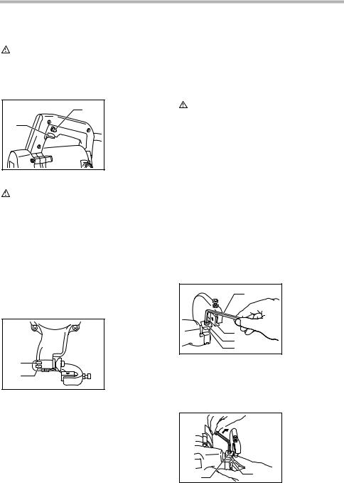
Switch action
004670 |
2 |
1 |
CAUTION: |
1.Switch trigger
2.Lock button
•Before plugging in the tool, always check to see that the switch trigger actuates properly and returns to the “OFF” position when released.
•Switch can be locked in “ON” position for ease of operator comfort during extended use. Apply caution when locking tool in “ON” position and maintain firm grasp on tool.
To start the tool, simply pull the switch trigger. Release the switch trigger to stop.
For continuous operation, pull the switch trigger and then push in the lock button.
To stop the tool from the locked position, pull the switch trigger fully, then release it.
Permissible shearing thickness
004675
1. Gauge for stainless: 2.5 mm (3/32”)
|
2. Gauge for mild |
1 |
steel: 3.2 mm |
(1/8”) |
2
The groove on the yoke serves as a thickness gauge for shearing mild or stainless steel plate. If the material fits within the groove, it is shearable.
The thickness of materials to be sheared depends upon the type (strength) of the material. The maximum shearing thickness is indicated in the table below in terms of various materials. Attempting to shear materials thicker than indicated will result in tool breakdown and/or possible injury. Keep within the thickness shown in the table.
|
|
006426 |
Max. cutting capacities |
mm |
ga |
Steel up to 400 N/mm2 |
3.2 |
10 |
Steel up to 600 N/mm2 |
2.5 |
13 |
Steel up to 800 N/mm2 |
1.5 |
17 |
Aluminum up to 200 N/mm2 |
4.0 |
9 |
ASSEMBLY
CAUTION:
•Always be sure that the tool is switched off and unplugged before carrying out any work on the tool.
Blade inspection
Before using the tool, check the blades for wear. Dull, worn blades will result in poor shearing action, and the service life of the tool will be shortened.
The service life of the blades varies in terms of the materials to be cut and the fixed blade clearance. Roughly speaking, a blade can cut about 500 m (1500 ft.) of 3.2 mm (10 ga.) mild steel with one cutting edge (total 2,000 m (6560 ft.) with four cutting edges).
Rotating or replacing blades
Both the upper and lower blades have four cutting edges on each side (the front and back). When the cutting edge becomes dull, rotate both the upper and the lower blades 90° to expose new cutting edges.
When all eight edges are dull on both the upper and lower blades, replace both blades with new ones. Each time blades are rotated or replaced, proceed as follows.
004679
1. Hex wrench
1
2. Lower blade
3. Upper blade securing bolt 4. Upper blade
2
3
4
Remove the blade securing bolts with the hex wrench provided and then rotate or replace the blades.
Install the upper blade and tighten the upper blade securing bolt with the hex wrench. Press up on the upper blade while tightening it.
|
004682 |
|
|
1. |
Tighten |
1 |
2. |
Upper blade |
|
|
securing bolt |
|
3. |
Upper blade |
 3 2
3 2
4

After securing the upper blade, be sure that there is no |
OPERATION |
gap left between the upper blade and the beveled sur- |
Holding material |
face of the blade holder. |
|
004683 |
|
004700 |
|
1. |
Blade holder |
1. Workholder |
1 |
2. |
Upper blade |
|
4 |
securing bolt |
|
|
|
|
||
|
Upper blade |
|
|
2 |
3. |
|
|
4. |
No gap allowed |
|
|
|
|
||
3 |
|
|
1 |
|
|
|
Then install the lower blade like the upper blade while adjusting the clearance between the upper blade and lower blades. When performing this adjustment, the upper blade should be in the lowered position.
|
004684 |
|
1 |
1. |
Lower blade |
|
positioning bolt |
|
|
2. |
Lower blade |
2 |
3. |
Upper blade |
|
|
 3
3
First, semitighten the lower blade securing bolt, then insert the thickness gauge for the desired clearance. The cutting thickness is indicated on the thickness gauge so the combinations shown in the table below should be used. Work the lower blade positioning bolt on the yoke until the clearance is such that the thickness gauge moves only with some difficulty. Then firmly tighten the lower blade securing bolt. Finally, tighten the hex nut to secure the lower blade positioning bolt.
|
|
004685 |
|
|
|
|
1. |
Lower blade |
|
|
|
|
positioning bolt |
|
|
|
2. |
Hex nut |
|
|
1 |
3. |
Thickness |
|
|
2 |
|
gauge |
|
|
3 |
|
|
|
Thickness gauge combinations |
|
|||
|
|
|
006427 |
|
Material thickness 2.3 mm (14 ga.) |
2.5 mm (13 ga.) 3.2 mm (10 ga.) |
|||
Thickness gauge |
1.0 +1.5 |
1.0 +1.5 |
1.5 + 2.0 |
|
combinations |
||||
|
|
|
||
The materials for cutting should be fastened to the workbench by means of workholders.
Shearing method
004702
For smooth cuts, tip the tool slightly backward while advancing it.
Maximum cutting width
004703
1. Cutting line
A1800 mm
(70-7/8")
 1
1
Stay within the specified maximum cutting width (A): Case of length 1,800 mm (70-7/8”).
|
|
006431 |
Mild steel (thickness) |
3.2 mm (10 ga) |
Under 2.3 mm (14 ga) |
Max. cutting width (A) |
90 mm (3-1/2") |
No limit |
|
|
|
Stainless (thickness) |
2.5 mm (13 ga) |
Under 2.0 mm (15 ga) |
Max. cutting width (A) |
70 mm (2-3/4") |
No limit |
Minimum cutting radius
Minimum cutting radius is 50 mm (2”) when cutting 2.3 mm (14 ga.) mild steel.
5
MAINTENANCE
CAUTION:
•Always be sure that the tool is switched off and unplugged before attempting to perform inspection or maintenance.
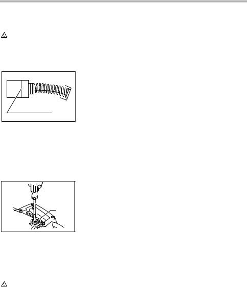
Replacing carbon brushes
001145
1. Limit mark
1
Remove and check the carbon brushes regularly. Replace when they wear down to the limit mark. Keep the carbon brushes clean and free to slip in the holders. Both carbon brushes should be replaced at the same time. Use only identical carbon brushes.
Use a screwdriver to remove the brush holder caps. Take out the worn carbon brushes, insert the new ones and secure the brush holder caps.
004707
1. Screwdriver
2. Brush holder
cap
 1
1
2
To maintain product SAFETY and RELIABILITY, repairs, any other maintenance or adjustment should be performed by Makita Authorized or Factory Service Centers, always using Makita replacement parts.
ACCESSORIES
CAUTION:
•These accessories or attachments are recommended for use with your Makita tool specified in this manual. The use of any other accessories or attachments might present a risk of injury to persons. Only use accessory or attachment for its stated purpose.
If you need any assistance for more details regarding these accessories, ask your local Makita Service Center.
•Blades
•Hex wrench
•Thickness gauge
EN0006-1
MAKITA LIMITED ONE YEAR WARRANTY
Warranty Policy
Every Makita tool is thoroughly inspected and tested before leaving the factory. It is warranted to be free of defects from workmanship and materials for the period of ONE YEAR from the date of original purchase. Should any trouble develop during this one year period, return the COMPLETE tool, freight prepaid, to one of Makita’s Factory or Authorized Service Centers. If inspection shows the trouble is caused by defective workmanship or material, Makita will repair (or at our option, replace) without charge.
This Warranty does not apply where:
•repairs have been made or attempted by others:
•repairs are required because of normal wear and tear:
•the tool has been abused, misused or improperly maintained:
•alterations have been made to the tool.
IN NO EVENT SHALL MAKITA BE LIABLE FOR ANY INDIRECT, INCIDENTAL OR CONSEQUENTIAL DAMAGES FROM THE SALE OR USE OF THE PRODUCT. THIS DISCLAIMER APPLIES BOTH DURING AND AFTER THE TERM OF THIS WARRANTY.
MAKITA DISCLAIMS LIABILITY FOR ANY IMPLIED WARRANTIES, INCLUDING IMPLIED WARRANTIES OF “MERCHANTABILITY” AND “FITNESS FOR A SPECIFIC PURPOSE,” AFTER THE ONE YEAR TERM OF THIS WARRANTY.
This Warranty gives you specific legal rights, and you may also have other rights which vary from state to state. Some states do not allow the exclusion or limitation of incidental or consequential damages, so the above limitation or exclusion may not apply to you. Some states do not allow limitation on how long an implied warranty lasts, so the above limitation may not apply to you.
6
 Loading...