

Page 1

R113 SP
Rotary Disc Header
Operator’s Manual
215009 Revision A
Original Instruction
The harvesting specialists.
Page 2

R113 SP Rotary Disc Header
1021763
Published June 2019.
© 2019 MacDon Industries, Ltd.
The information in this publication is based on the information available and in effect at the time of printing. MacDon
Industries, Ltd. makes no representation or warranty of any kind, whether expressed or implied, with respect to the
information in this publication. MacDon Industries, Ltd. reserves the right to make changes at any time without notice.
Noise Levels
The A-weighted sound pressure level inside the operator’s station of a typical self-propelled vehicle (e.g., M1170), when
operated in conjunction with this R1 SP Series Disc Header, is 70 dBA. This measurement was taken in accordance with
ISO 5131. The sound pressure level depends upon the rotary disc speed, crop conditions, as well the exact type of selfpropelled vehicle used to power the R1 SP Series Disc Header.
Page 3

Declaration of Conformity
1029750
Figure 1: EC Declaration of Conformity
215009 i Revision A
Page 4

Figure 2: EC Declaration of Conformity
1029751
215009 ii Revision A
Page 5

Introduction
1003980
A
This instructional manual contains safety, operating, and maintenance procedures for the MacDon R113 Rotary Disc Header
The disc header when attached to a MacDon M155, M155E4, M1170, or M1240 Windrower, is designed to cut, condition,
and lay a wide variety of grasses and hay crops in windrows.
Carefully read all the material provided before attempting to unload, assemble, or use the machine.
Use this manual as your first source of information about the machine. If you follow the instructions provided in this
manual, and use MacDon parts, the rotary disc header will work well for many years. If you require more detailed service
information, contact your Dealer.
Use the Table of Contents and the Index to guide you to specific topics. Study the Table of Contents to familiarize yourself
with how the material is organized. Keep this manual handy for frequent reference and to pass on to new Operators or
Owners. Call your Dealer if you need assistance, information, or additional copies of this manual.
When setting up the machine or making adjustments, review and follow the recommended machine settings in all relevant
MacDon publications. Failure to do so may compromise machine function and machine life and may result in a hazardous
situation.
MacDon provides warranty for Customers who operate and maintain their equipment as described in this manual. A copy
of the MacDon Industries Limited Warranty Policy, which explains this warranty, should have been provided to you by your
Dealer. Damage resulting from any of the following conditions will void the warranty:
• Accident
• Misuse
• Abuse
• Improper maintenance or neglect
• Abnormal or extraordinary use of the machine
• Failure to use the machine, equipment, component, or part in accordance with the manufacturer’s instructions
Conventions
The following conventions are used in this document:
• Right and left are determined from the operator’s position. The front of the rotary disc header faces the crop.
• Unless otherwise noted, use the standard torque values provided in this manual.
Store the operator’s manual and the parts catalog in the plastic
manual case (A) at the right side of the rotary disc header.
NOTE: Keep your MacDon publications up-to-date. The most
current version can be downloaded from our website www.
macdon.com or from our Dealer-only site
(https://portal.macdon.com) (login required).
Manual Storage Case
215009 iii Revision A
Page 6

Summary of Changes
The following list provides an account of major changes from the previous version of this document.
Section Summary of Change
Throughout manual
Removed R116 SP-specific content from book.
Internal Use
Only
Tech Pubs
1.2 Signal Words, page 2
2.3 Definitions, page 19
• 3.3.1 Engaging and Disengaging
Header Safety Props – M1240
Windrower, page 24
• 3.3.2 Engaging and Disengaging
Header Safety Props – M Series
Self-Propelled Windrower, page 25
3.4.1 Attaching R113 SP Rotary Disc
Header to M1 Series Windrowers, page 27
• 3.4.2 Attaching R113 SP to M155 or
M155E4 SP Windrowers – Hydraulic
Center-Link with Optional
Self-Alignment, page 32
• 3.4.3 Attaching R113 SP to M155 or
M155E4 SP Windrower – Hydraulic
Center-Link without Optional
Self-Alignment, page 37
Added description for IMPORTANT and NOTE signal words
appearing throughout this manual.
New definitions added: cab-forward, export header,
header, North American header, rpm, and windrower.
Updated illustrations to show MY2020 safety props.
Updated illustrations to show MY2020 safety props.
Updated float linkage and safety prop illustrations.
Tech Pubs
Tech Pubs
ECN 58047
ECN 58047
ECN 58047
Connecting Header Hydraulics and
Electrical – M155 and M155E4 SP
Windrowers, page 45
3.5 Detaching Header from M1240
Windrower, page 52
3.8.4 Ground Speed, page 70
3.9 Reconfiguring Cutterbar Crop Stream,
page 71
Positioning Rear Baffle – Roll Conditioner,
page 82
Positioning Rear Baffle Deflector Fins,
page 83
4.3.1 Maintenance Schedule/Record, page
93
4.5 Cutterbar System, page 99 Updated cutterbar illustration. Tech Pubs
Draining the Cutterbar, page 102 Updated illustration. Tech Pubs
Inspecting Cutterbar Discs, page 104 Added steps to procedure. Tech Pubs
215009 iv Revision A
Updated illustrations for hydraulic connections.
Updated illustrations to show MY2020 safety props.
Updated ground speed chart to only show R113 SP
headers.
Updated cutterbar configuration illustration.
Updated illustration. Tech Pubs
Updated illustration for deflector fins in field position.
Updated maintenance intervals. Tech Pubs
Tech Pubs
ECN 58047
Tech Pubs
Tech Pubs
Tech Pubs
Page 7

Internal Use
Section Summary of Change
Only
4.5.4 Maintaining Discblades, page 118 Updated disc rotation illustrations. Tech Pubs
Inspecting Accelerators, page 125 Updated accelerators illustration. Tech Pubs
Installing Accelerators, page 127 Updated cutterbar door illustration. Tech Pubs
Inspecting Rock Guards, page 129 Updated rock guard illustration. Tech Pubs
Inspecting Large Drums, page 135
Installing Large Driven Drums and
Driveline, page 140
Printed on the manual’s back cover.
Updated cutterbar drum illustration. Tech Pubs
Updated topic illustrations. Tech Pubs
Updated grease description for conditioner roll timing
gearbox.
Tech Pubs,
Product
Support
215009 v Revision A
Page 8

Model and Serial Number
Record the model number, serial number, and model year of the header on the lines below.
R113 SP
Header Model:
Serial Number:
Year:
The serial number plate (A) is located near the base of the
right side hazard/signal light on the right edge of the header.
A
Figure 3: Right Side of Header
1021877
215009 vi Revision A
Page 9

TABLE OF CONTENTS
Declaration of Conformity ..............................................................................................................................i
Introduction .............................................................................................................................................. iii
Summary of Changes................................................................................................................................... iv
Model and Serial Number ............................................................................................................................ vi
Chapter 1: Safety ........................................................................................................................................ 1
1.1 Safety Alert Symbols ...............................................................................................................................1
1.2 Signal Words .........................................................................................................................................2
1.3 General Safety .......................................................................................................................................3
1.4 Maintenance Safety ................................................................................................................................5
1.5 Hydraulic Safety .. ... ................................................................................................................................6
1.6 Welding Precaution ................................................................................................................................7
1.7 Safety Signs ...........................................................................................................................................8
1.7.1 Installing Safety Decals....................................................................................................................8
1.8 Locating Safety Decals .............................................................................................................................9
1.9 Understanding Safety Signs .................................................................................................................... 11
Chapter 2: Product Overview................................................................................................................... 15
2.1 Specifications....................................................................................................................................... 15
2.2 Component Identification ...................................................................................................................... 17
2.3 Definitions .......................................................................................................................................... 19
Chapter 3: Operation................................................................................................................................ 21
3.1 Break-In Period .................................................................................................................................... 21
3.2 Daily Start-Up Check ............................................................................................................................. 22
3.3 Engaging and Disengaging Header Safety Props ......................................................................................... 24
3.3.1 Engaging and Disengaging Header Safety Props – M1240 Windrower . ................................................... 24
3.3.2 Engaging and Disengaging Header Safety Props – M Series Self-Propelled Windrower .............................. 25
3.4 Attaching Header to Windrower . ............................................................................................................. 27
3.4.1 Attaching R113 SP Rotary Disc Header to M1 Series Windrowers.......................................................... 27
3.4.2 Attaching R113 SP to M155 or M155E4 SP Windrowers – Hydraulic Center-Link with Optional
Self-Alignment...................................................................................................................... 32
3.4.3 Attaching R113 SP to M155 or M155E4 SP Windrower – Hydraulic Center-Link without Optional
Self-Alignment...................................................................................................................... 37
3.4.4 Attaching Hydraulic and Electrical Components ................................................................................. 42
Connecting Header Hydraulics and Electrical – M1 Series Windrowers ................................................. 42
Connecting Header Hydraulics and Electrical – M155 and M155E4 SP Windrowers................................. 45
3.5 Detaching Header from M1240 Windrower ............................................................................................... 52
3.5.1 Detaching – M1 Series Windrower .................................................................................................. 52
3.5.2 Detaching R1 SP Series Header – M155 and M155E4 Windrowers ........................................................ 57
3.6 Driveshields ......................................................................................................................................... 61
3.6.1 Opening Driveshields .................................................................................................................... 61
3.6.2 Closing Driveshields...................................................................................................................... 62
215009 vii Revision A
Page 10

TABLE OF CONTENTS
3.7 Cutterbar Doors ................................................................................................................................... 64
3.7.1 Opening Cutterbar Doors – North America . .. .................................................................................... 64
3.7.2 Opening Cutterbar Doors – Export Latches ....................................................................................... 65
3.7.3 Closing Cutterbar Doors .... ............................................................................................................ 66
3.8 Header Settings.................................................................................................................................... 67
3.8.1 Cutting Height ............................................................................................................................. 67
Adjusting Cutting Height .............................................................................................................. 68
3.8.2 Adjusting Cutterbar Angle. ............................................................................................................. 69
3.8.3 Header Float ............................................................................................................................... 69
3.8.4 Ground Speed ............................................................................................................................. 70
3.9 Reconfiguring Cutterbar Crop Stream.. ..................................................................................................... 71
3.9.1 Changing R113 SP Cutterbar Crop Stream Configuration .... ................................................................. 72
3.10 Conditioner ....................................................................................................................................... 73
3.10.1 Roll Gap.................................................................................................................................... 73
Checking Roll Gap ....................................................................................................................... 74
Adjusting Roll Gap – Polyurethane Rolls.......................................................................................... 75
Adjusting Roll Gap – Steel Rolls ..................................................................................................... 76
3.10.2 Roll Tension . ............................................................................................................................. 77
Adjusting Roll Tension ................................................................................................................. 77
3.10.3 Roll Timing ................................................................................................................................ 78
Checking Roll Timing ................................................................................................................... 78
Adjusting Roll Timing ................................................................................................................... 78
3.10.4 Adjusting Forming Shields – Roll Conditioner................................................................................... 81
Positioning Forming Shield Side Deflectors – Roll Conditioner............................................................. 81
Positioning Rear Baffle – Roll Conditioner ....................................................................................... 82
3.11 Cutterbar Deflectors.. .......................................................................................................................... 84
3.11.1 Removing Cutterbar Deflectors ..................................................................................................... 84
3.11.2 Installing Cutterbar Deflectors . ..................................................................................................... 85
3.12 Haying Tips ........................................................................................................................................ 86
3.12.1 Curing ...................................................................................................................................... 86
3.12.2 Topsoil Moisture ........................................................................................................................ 86
3.12.3 Weather and Topography ............................................................................................................ 86
3.12.4 Windrow Characteristics .............................................................................................................. 87
3.12.5 Driving on Windrow .................................................................................................................... 87
3.12.6 Using Chemical Drying Agents ...................................................................................................... 87
3.13 Transporting the Header ...................................................................................................................... 88
Chapter 4: Maintenance and Servicing.................................................................................................... 89
4.1 Preparing Machine for Servicing .............................................................................................................. 89
4.2 Recommended Safety Procedures ........................................................................................................... 90
4.3 Maintenance Requirements ................................................................................................................... 92
4.3.1 Maintenance Schedule/Record ....................................................................................................... 93
4.3.2 Break-In Inspections ..................................................................................................................... 95
4.3.3 Preseason Servicing ...................................................................................................................... 95
4.3.4 End-of-Season Servicing .... ............................................................................................................ 96
215009 viii Revision A
Page 11

TABLE OF CONTENTS
4.4 Lubrication .......................................................................................................................................... 97
4.4.1 Greasing Procedure ...................................................................................................................... 97
Every 25 Hours ........................................................................................................................... 98
4.5 Cutterbar System.................................................................................................................................. 99
4.5.1 Lubricating Cutterbar.................................................................................................................... 99
Checking and Adding Cutterbar Lubricant .. . .................................................................................... 99
Draining the Cutterbar.. .. . .......................................................................................................... 102
Filling Lubricant into a Repaired Cutterbar .................................................................................... 103
4.5.2 Maintaining Cutterbar Discs ......................................................................................................... 104
Inspecting Cutterbar Discs .......................................................................................................... 104
Removing Cutterbar Discs .......................................................................................................... 106
Installing Cutterbar Discs............................................................................................................ 108
4.5.3 Replacing Cutterbar Spindles........................................................................................................ 109
Removing Cutterbar Spindles ...................................................................................................... 111
Installing Cutterbar Spindles ....................................................................................................... 114
4.5.4 Maintaining Discblades ............................................................................................................... 118
Inspecting Discblades ................................................................................................................ 119
Inspecting Discblade Hardware ................................................................................................... 121
Removing Discblades ................................................................................................................. 122
Installing Discblades .................................................................................................................. 124
4.5.5 Maintaining Accelerators............................................................................................................. 125
Inspecting Accelerators .............................................................................................................. 125
Removing Accelerators . .. ........................................................................................................... 126
Installing Accelerators .. ... .......................................................................................................... 127
4.5.6 Maintaining Rock Guards............................................................................................................. 129
Inspecting Rock Guards.............................................................................................................. 129
Removing Inboard Rock Guards................................................................................................... 130
Installing Inboard Rock Guards .................................................................................................... 131
Removing Outboard Rock Guards ................................................................................................ 132
Installing Outboard Rock Guards . ................................................................................................ 133
4.5.7 Maintaining Large Drums ............................................................................................................ 134
Inspecting Large Drums ............................................................................................................. 135
Removing Large Driven Drums and Driveline ................................................................................. 136
Installing Large Driven Drums and Driveline................................................................................... 140
Removing Large Non-Driven Drums ............................................................................................. 145
Installing Large Non-Driven Drums ............................................................................................... 147
4.5.8 Replacing Cutterbar Spindle Shear Pin ........................................................................................... 149
Removing Cutterbar Spindle Shear Pin . ......................................................................................... 150
Installing Cutterbar Spindle Shear Pin ........................................................................................... 154
4.6 Conditioner Roll Timing Gearbox .......................................................................................................... 158
4.6.1 Checking and Changing Oil in Conditioner Roll Timing Gearbox (MD #221748 or MD #307211)................ 158
4.7 Servicing Header Drive Gearbox ............................................................................................................ 161
4.7.1 Changing Header Drive Gearbox Oil............................................................................................... 161
4.8 Inspecting Cutterbar Doors................................................................................................................... 163
4.9 Maintaining Curtains ........................................................................................................................... 164
4.9.1 Inspecting Curtains ..................................................................................................................... 164
4.9.2 Removing Cutterbar Door Curtains................................................................................................ 165
4.9.3 Installing Cutterbar Door Curtains ................................................................................................. 165
4.9.4 Removing Cutterbar Inboard Curtain ............................................................................................. 166
215009 ix Revision A
Page 12

TABLE OF CONTENTS
4.9.5 Installing Cutterbar Inboard Curtain .............................................................................................. 167
4.9.6 Removing Outboard Curtains ....................................................................................................... 168
4.9.7 Installing Outboard Curtains ........................................................................................................ 169
4.10 Conditioner System ........................................................................................................................... 170
4.10.1 Inspecting Roll Conditioner ........................................................................................................ 170
4.10.2 Conditioner Drive Belt............................................................................................................... 172
Inspecting Conditioner Drive Belt ................................................................................................ 172
Removing Conditioner Drive Belt ................................................................................................. 174
Installing Conditioner Drive Belt .................................................................................................. 175
4.10.3 Changing the Conditioner .......................................................................................................... 177
Removing the Conditioner .......................................................................................................... 177
Installing the Conditioner ........................................................................................................... 181
Installing Conditioner Drive ........................................................................................................ 185
4.10.4 Replacing Shield – No Conditioner ............................................................................................... 186
Removing Discharge Shield (No Conditioner) ................................................................................. 186
Installing Discharge Shield (No Conditioner) . ................................................................................. 187
4.10.5 Replacing Driveshields............................................................................................................... 188
Removing Driveshields............................................................................................................... 188
Installing Driveshields ................................................................................................................ 190
Replacing Driveshield Latch . . .. .................................................................................................... 191
4.11 Electrical System............................................................................................................................... 192
4.11.1 Maintaining Electrical System ..................................................................................................... 192
4.11.2 Replacing Amber Hazard/Signal Light Fixture................................................................................. 193
4.11.3 Replacing Amber Hazard/Signal Bulb ........................................................................................... 193
4.11.4 Replacing Header RPM Sensor .................................................................................................... 194
4.12 Hydraulics .. . .................................................................................................................................... 195
4.12.1 Checking Hydraulic Hoses and Lines............................................................................................. 195
Chapter 5: Options and Attachments.................................................................................................... 197
5.1 Performance Kits ................................................................................................................................ 197
5.1.1 Tall Crop Divider Kit .................................................................................................................... 197
5.1.2 No Conditioner Kit ..................................................................................................................... 197
5.1.3 Polyurethane Roll Conditioner Kit ................................................................................................. 197
5.1.4 Steel Roll Conditioner Kit ............................................................................................................. 197
5.2 Hydraulic Drive Conversion Kits............................................................................................................. 198
5.2.1 M1 Series Hydraulic Drive Conversion Kit ....................................................................................... 198
5.2.2 M1240 Case Drain Kit ................................................................................................................. 198
5.2.3 M155 and M155E4 Hydraulic Drive Conversion Kit . .......................................................................... 199
Chapter 6: Troubleshooting.................................................................................................................... 201
6.1 Performance Problems ........................................................................................................................ 201
6.2 Mechanical Problems.. ........................................................................................................................ 205
Chapter 7: Reference.............................................................................................................................. 209
7.1 Torque Specifications .......................................................................................................................... 209
7.1.1 Metric Bolt Specifications.. .......................................................................................................... 209
215009 x Revision A
Page 13

TABLE OF CONTENTS
7.1.2 Metric Bolt Specifications Bolting into Cast Aluminum ...................................................................... 211
7.1.3 O-Ring Boss Hydraulic Fittings – Adjustable .................................................................................... 212
7.1.4 O-Ring Boss Hydraulic Fittings – Non-Adjustable .............................................................................. 214
7.1.5 O-Ring Face Seal Hydraulic Fittings ................................................................................................ 215
7.1.6 Tapered Pipe Thread Fittings........................................................................................................ 216
7.2 Conversion Chart ................................................................................................................................ 217
Index........................................................................................................................................................ 219
Recommended Lubricants ...................................................................................................................... 225
215009 xi Revision A
Page 14

Page 15

Chapter 1: Safety
1000915
1.1 Safety Alert Symbols
This safety alert symbol indicates important safety messages in
this manual and on safety signs on the machine.
This symbol means:
• ATTENTION!
• BECOME ALERT!
• YOUR SAFETY IS INVOLVED!
Carefully read and follow the safety message accompanying this
symbol.
Why is safety important to you?
• Accidents disable and kill
• Accidents cost
• Accidents can be avoided
Figure 1.1: Safety Symbol
215009 1 Revision A
Page 16

SAFETY
1.2 Signal Words
Three signal words, DANGER, WARNING, and CAUTION, are used to alert you to hazardous situations. Two signal words,
IMPORTANT and NOTE, identify non-safety related information. Signal words are selected using the following guidelines:
DANGER
Indicates an imminently hazardous situation that, if not avoided, will result in death or serious injury.
WARNING
Indicates a potentially hazardous situation that, if not avoided, could result in death or serious injury. It may also be
used to alert against unsafe practices.
CAUTION
Indicates a potentially hazardous situation that, if not avoided, may result in minor or moderate injury. It may be used
to alert against unsafe practices.
IMPORTANT:
Indicates a situation that, if not avoided, could result in a malfunction or damage to the machine.
NOTE:
Provides additional information or advice.
215009 2 Revision A
Page 17

1000004
1000005
1010391
SAFETY
1.3 General Safety
CAUTION
The following general farm safety precautions should be part of
your operating procedure for all types of machinery.
Protect yourself.
• When assembling, operating, and servicing machinery, wear
all protective clothing and personal safety devices that could
be necessary for job at hand. Do NOT take chances. You may
need the following:
• Hard hat
• Protective footwear with slip-resistant soles
• Protective glasses or goggles
• Heavy gloves
• Wet weather gear
• Respirator or filter mask
• Be aware that exposure to loud noises can cause hearing
impairment or loss. Wear suitable hearing protection devices
such as earmuffs or earplugs to help protect against loud
noises.
• Provide a first aid kit in case of emergencies.
• Keep a properly maintained fire extinguisher on the machine.
Be familiar with its proper use.
Figure 1.2: Safety Equipment
Figure 1.3: Safety Equipment
• Keep young children away from machinery at all times.
• Be aware that accidents often happen when the operator is
tired or in a hurry. Take time to consider safest way. NEVER
ignore warning signs of fatigue.
Figure 1.4: Safety Equipment
215009 3 Revision A
Page 18

SAFETY
• Wear close-fitting clothing and cover long hair. NEVER wear
dangling items such as scarves or bracelets.
• Keep all shields in place. NEVER alter or remove safety
equipment. Make sure driveline guards can rotate
independently of shaft and can telescope freely.
• Use only service and repair parts made or approved by
equipment manufacturer. Substituted parts may not meet
strength, design, or safety requirements.
• Keep hands, feet, clothing, and hair away from moving parts.
NEVER attempt to clear obstructions or objects from a
machine while engine is running.
• Do NOT modify machine. Unauthorized modifications may
impair machine function and/or safety. It may also shorten
machine’s life.
1000007
Figure 1.5: Safety around Equipment
• To avoid injury or death from unexpected startup of machine,
ALWAYS stop the engine and remove the key from the
ignition before leaving the operator’s seat for any reason.
• Keep service area clean and dry. Wet or oily floors are
slippery. Wet spots can be dangerous when working with
electrical equipment. Be sure all electrical outlets and tools
are properly grounded.
• Keep work area well lit.
• Keep machinery clean. Straw and chaff on a hot engine is a
fire hazard. Do NOT allow oil or grease to accumulate on
service platforms, ladders, or controls. Clean machines before
storage.
• NEVER use gasoline, naphtha, or any volatile material for
cleaning purposes. These materials may be toxic and/or
flammable.
• When storing machinery, cover sharp or extending
components to prevent injury from accidental contact.
1000008
Figure 1.6: Safety around Equipment
1000009
Figure 1.7: Safety around Equipment
215009 4 Revision A
Page 19
1000009
1008958
1000004
SAFETY
1.4 Maintenance Safety
To ensure your safety while maintaining machine:
• Review operator’s manual and all safety items before
operation and/or maintenance of machine.
• Place all controls in Neutral, stop the engine, set the park
brake, remove the ignition key, and wait for all moving parts
to stop before servicing, adjusting, and/or repairing.
• Follow good shop practices:
– Keep service areas clean and dry
– Be sure electrical outlets and tools are properly grounded
– Keep work area well lit
• Relieve pressure from hydraulic circuits before servicing
and/or disconnecting machine.
• Make sure all components are tight and that steel lines,
hoses, and couplings are in good condition before applying
pressure to hydraulic systems.
Figure 1.8: Safety around Equipment
• Keep hands, feet, clothing, and hair away from all moving
and/or rotating parts.
• Clear area of bystanders, especially children, when carrying
out any maintenance, repairs, or adjustments.
• Install transport lock or place safety stands under frame
before working under machine.
• If more than one person is servicing machine at same time,
be aware that rotating a driveline or other mechanicallydriven component by hand (for example, accessing a
lubricant fitting) will cause drive components in other areas
(belts, pulleys, and knives) to move. Stay clear of driven
components at all times.
• Wear protective gear when working on machine.
• Wear heavy gloves when working on knife components.
Figure 1.9: Equipment NOT Safe for Children
Figure 1.10: Safety Equipment
215009 5 Revision A
Page 20

SAFETY
1.5 Hydraulic Safety
• Always place all hydraulic controls in Neutral before
dismounting.
• Make sure that all components in hydraulic system are kept
clean and in good condition.
• Replace any worn, cut, abraded, flattened, or crimped hoses
and steel lines.
• Do NOT attempt any makeshift repairs to hydraulic lines,
fittings, or hoses by using tapes, clamps, cements, or welding.
The hydraulic system operates under extremely highpressure. Makeshift repairs will fail suddenly and create
hazardous and unsafe conditions.
• Wear proper hand and eye protection when searching for
high-pressure hydraulic leaks. Use a piece of cardboard as a
backstop instead of hands to isolate and identify a leak.
• If injured by a concentrated high-pressure stream of
hydraulic fluid, seek medical attention immediately. Serious
infection or toxic reaction can develop from hydraulic fluid
piercing the skin.
1001205
Figure 1.11: Testing for Hydraulic Leaks
• Make sure all components are tight and steel lines, hoses,
and couplings are in good condition before applying pressure
to a hydraulic system.
1001207
Figure 1.12: Hydraulic Pressure Hazard
1000013
Figure 1.13: Safety around Equipment
215009 6 Revision A
Page 21

SAFETY
1.6 Welding Precaution
Welding should never be attempted on the header while it is connected to a windrower.
WARNING
Severe damage to sensitive, expensive electronics can result from welding on the header while it is connected to the
windrower. It can be impossible to know what effect high current could have with regard to future malfunctions or
shorter lifespan. It is very important that welding on the header is not attempted while the header is connected to the
windrower.
If an Operator needs to do any welding on the header, it should first be disconnected and removed from the windrower.
If it is unfeasible to disconnect the header from the windrower before attempting welding, contact your MacDon Dealer for
welding precautions detailing all electrical components that must be disconnected first for safe welding.
215009 7 Revision A
Page 22

SAFETY
1.7 Safety Signs
• Keep safety signs clean and legible at all times.
• Replace safety signs that are missing or illegible.
• If original part on which a safety sign was installed is
replaced, be sure the repair part displays the current
safety sign.
• Replacement safety signs are available from your MacDon
Dealer Parts Department.
1.7.1 Installing Safety Decals
1. Clean and dry installation area.
1000694
Figure 1.14: Operator’s Manual Decal
2. Decide on exact location before you remove decal backing paper.
3. Remove smaller portion of split backing paper.
4. Place decal in position and slowly peel back remaining paper, smoothing decal as it is applied.
5. Prick small air pockets with a pin and smooth out.
215009 8 Revision A
Page 23

1.8 Locating Safety Decals
Figure 1.15: Safety Sign Decal Locations Top View
SAFETY
F
E
D
A
B
C
A - MD #194466 B - MD #247167 C - MD #194465
D - MD #166466 E - MD #113482 F - MD #190546
Figure 1.16: Safety Sign Decals
A
D
B
E
1021067
C
F
215009 9 Revision A
1023551
Page 24

Figure 1.17: Safety Sign Decal Locations Roll Conditioner
SAFETY
B
C
F
C
B
F
A
E
A - MD #190546 B - MD #184385 C - MD #184371
D - MD #246959 E - MD #246956 F - NO STEP Symbol (Imprinted on Shield)
215009 10 Revision A
D
D
E
1024756
Page 25

1000917
1029243
SAFETY
1.9 Understanding Safety Signs
NOTE:
This is a general list of safety sign definitions and the decals listed may not necessarily be applicable to your machine.
MD #113482
General hazard pertaining to machine operation and servicing.
CAUTION
• Read the operator’s manual, and follow all safety
instructions. If you do not have a manual, obtain one from
your Dealer.
• Do NOT allow untrained persons to operate the machine.
• Review safety instructions with all Operators annually.
• Ensure that all safety signs are installed and legible.
• Make certain everyone is clear of machine before starting
engine, and during operation.
• Keep riders off the machine.
Figure 1.18: MD #113482
• Keep all shields in place and stay clear of moving parts.
• Disengage self-propelled rotary disc header drive, put
transmission in Neutral, and wait for all movement to stop
before leaving operator’s position.
• Shut off engine and remove key from ignition before
servicing, adjusting, lubricating, cleaning, or unplugging
machine.
• Engage locks to prevent lowering of self-propelled rotary
disc header before servicing in the raised position.
• Use slow moving vehicle emblem and flashing warning lights
when operating on roadways unless prohibited by law.
MD #166832
Hydraulic pressure oil hazard
WARNING
• High pressure oil easily punctures skin causing serious injury,
gangrene, or death.
• If injured, seek emergency medical help.
• Do NOT use finger or skin to check for leaks.
• Lower load or relieve hydraulic pressure before loosening
fittings.
Figure 1.19: MD #166832
215009 11 Revision A
Page 26

SAFETY
MD #184371
Open drive hazard
WARNING
• Guard missing. Do NOT operate.
• Keep all shields in place.
MD #184385
Entanglement hazard
CAUTION
• To avoid injury from entanglement with rotating auger, stand
clear of header while machine is running.
1001648
Figure 1.20: MD #184371
MD #190546
Slippery surface
WARNING—DO NOT STEP ON SURFACE
• Do NOT use this area as a step or platform.
• Failure to comply could result in serious injury or death.
1000922
Figure 1.21: MD #184385
1004138
Figure 1.22: MD #190546
215009 12 Revision A
Page 27
1004140
1004141
1015207
SAFETY
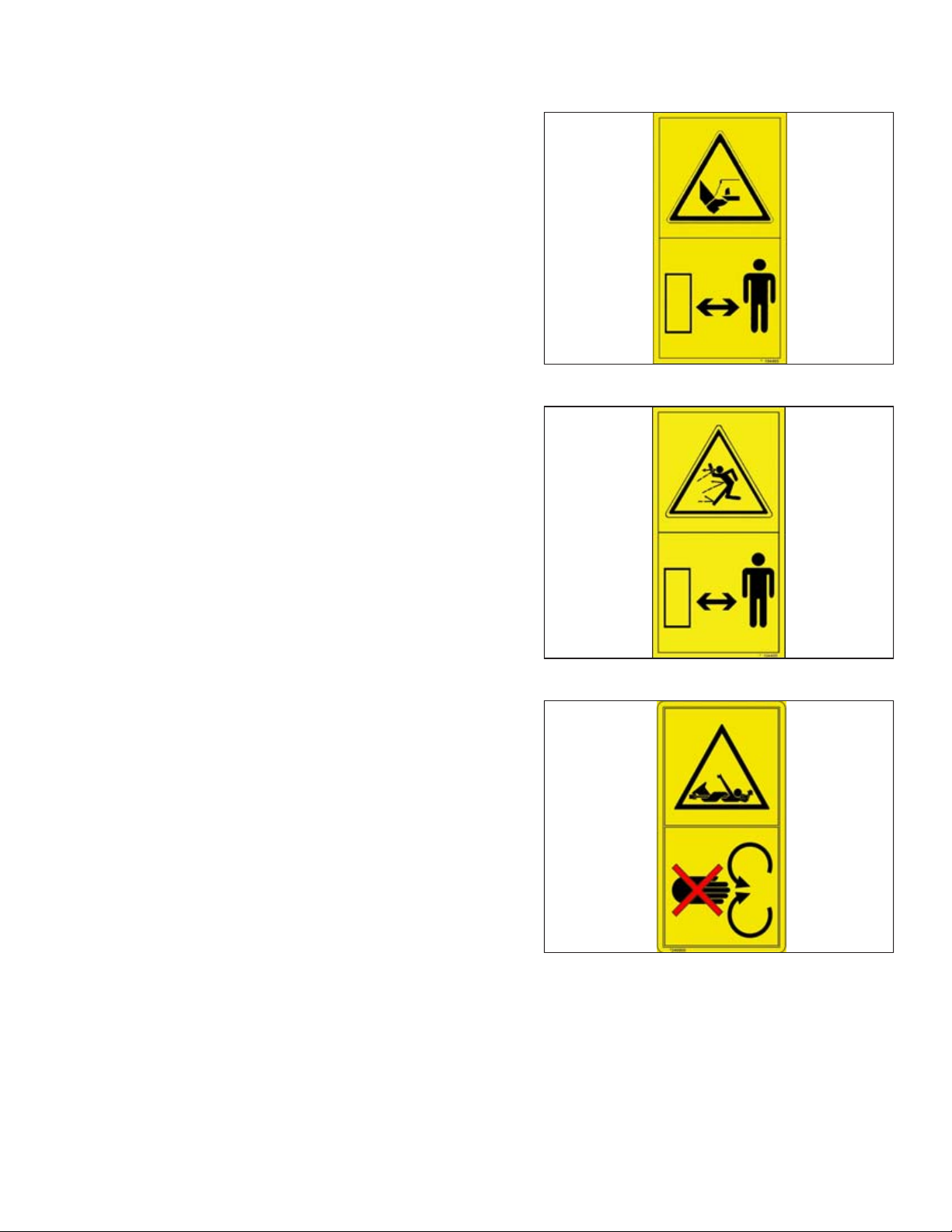
MD #194465
Rotating cutters
WARNING—STAND CLEAR
• Contact with blades or thrown objects can result in serious
injury or death.
• Do NOT stand on or near machine when in operation.
• Do NOT operate with covers or curtains open or removed.
• Shut off tractor and remove key before opening covers.
MD #194466
Rotating fingers under hood
WARNING—STAND CLEAR
• Crop materials exiting at high speed.
Figure 1.23: MD #194465
• Stop machine, look, listen, and wait for all movement to stop
before approaching.
• Failure to comply could result in death or serious injury.
MD #246956
Keep shields in place
WARNING
• Do NOT operate without shields/guards in place.
• Failure to comply will result in death or serious injury.
Figure 1.24: MD #194466
Figure 1.25: MD #246956
215009 13 Revision A
Page 28

SAFETY
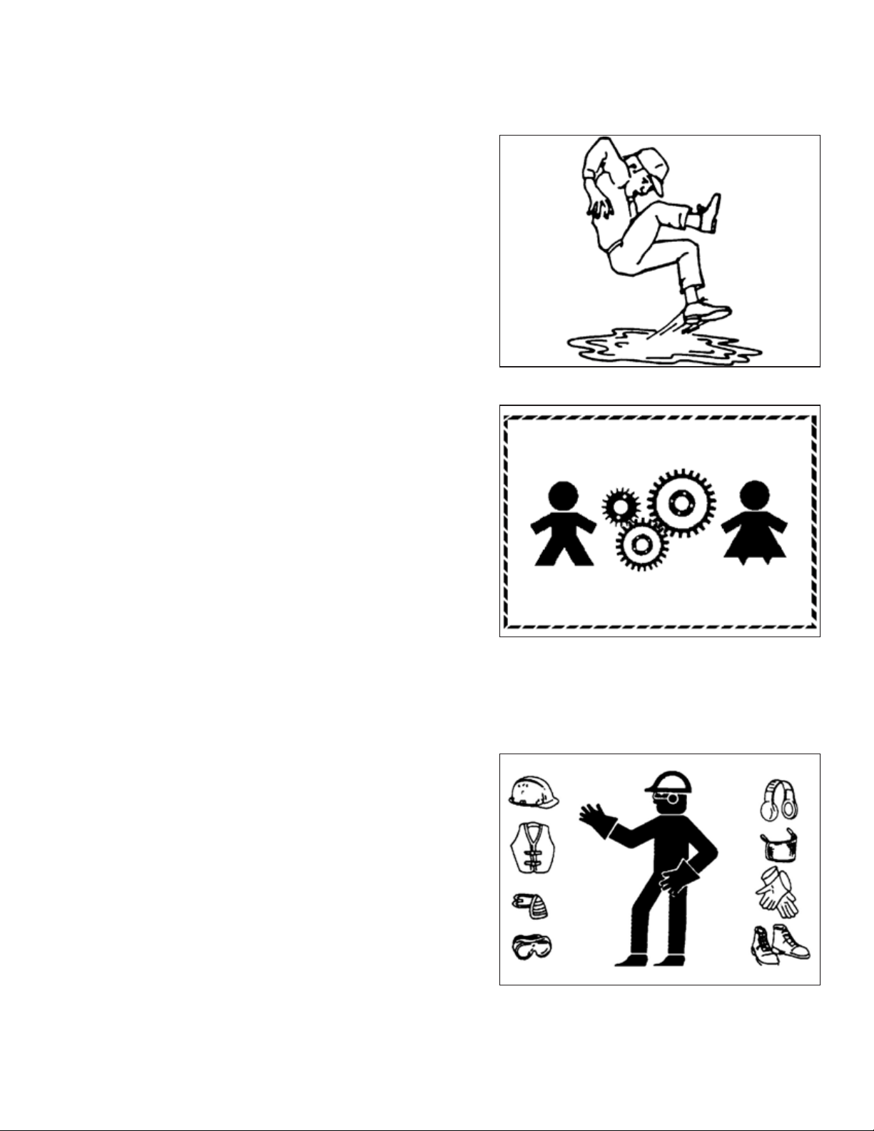
MD #246959
Pinch hazard
WARNING—KEEP AWAY
• Failure to comply could result in death or serious injury.
MD #247167
Rotating blades
WARNING
• Disengage power take-off, shut off tractor, and remove key
before opening covers.
1004137
Figure 1.26: MD #246959
• Listen and look for evidence of rotation before lifting cover.
• Cutters may continue to rotate after power is shut off due to
inertia.
1010589
Figure 1.27: MD #247167
215009 14 Revision A
Page 29

Chapter 2: Product Overview
2.1 Specifications
NOTE:
Specifications and design are subject to change without notice or obligation to revise previously sold units.
R113 SP
Frame and Structure
Width (transport)
Weight: base machine and adapter frame
Weight: base machine, adapter frame, and steel conditioner
Weight: base machine, adapter frame, and polyurethane
conditioner
Compatible windrower
Lighting
Manual storage
Cutterbar
Number of cutting discs
Blades per disc
Disc speed (full engine speed)
MacDon M155, M155 E4, M1170,
Plastic case on header right driveshield
4063 mm (160 in.)
1364 kg (3007 lb.)
1850 kg (4079 lb.)
1868 kg (4118 lb.)
or M1240 Windrower
Left and right turn signals
Eight
Two 18 degrees bevel down
2500 rpm
Blade max tip speed
Effective cutting width
Minimum Cutting height
Cutting angle range
Adjustable shoes
Gear train protection
Converging Drums
Drives
Hydraulic motor Piston type into 90-degree gearbox
Cutterbar
Conditioner drive
Conditioner roll timing
Direct drive through 90-degree gearbox and
Belt drive (4HB) from 90-degree gearbox to
80.5 m/s (180 mph)
3978 mm (13 ft.)
27 mm (1 1/16 in.)
0–8 degrees below horizontal
Standard
Shearpin (safecut)
Two-drum type
universal shaft
conditioner
Timing gearbox
215009 15 Revision A
Page 30

PRODUCT OVERVIEW
R113 SP
Hay Conditioner Options
Steel rolls Optional
Roll type Steel on steel chevron conditioner rolls
Roll length
Roll diameter
Roll speed
229 mm (9.0 in.) / 179 mm (7.0 in.) OD tube
3275 mm (129 in.)
1009 rpm
Polyurethane rolls Optional
Roll type Polyurethane intermeshing conditioner rolls
Roll length
Roll diameter
Roll speed
Swath width
1
Forming shields
No conditioner
254 mm (10.0 in.) / 203 mm (8.0 in.) OD tube
Full width adjustable baffle on conditioner with
adjustable side deflectors on support frame
3275 mm (129 in.)
1009 rpm
915–2540 mm (36–102 in.)
Optional (includes rear curtain)
1. Actual swath width may vary based upon conditioner type, crop type, and crop volume.
215009 16 Revision A
Page 31

2.2 Component Identification
Figure 2.1: R113 SP
PRODUCT OVERVIEW
H
G
F
J
K
L
B
A
A - Front Curtains B - Cutterbar Doors C - Drive Shield (Left)
D - Hose Support
G - Center-Link Tube H - Hazard/Brake Lights J - Disc Drum (Right)
K - Conditioner Rolls L - 8-Disc Cutterbar
2
E - Hydraulic Motor
3
F - Hose Support
D
E
C
1020889
2. M155/M155E4 SP Windrower only
3. M155/M155E4 SP Windrower motor shown
215009 17 Revision A
Page 32

Figure 2.2: R113 SP
PRODUCT OVERVIEW
D
C
B
A
E
F
1023134
A - Header Supports B - Side Deflectors C - Side Deflector Adjuster Handles
D - Rear Crop Baffle E - Adapter Frame F - Drive Shield
215009 18 Revision A
Page 33

PRODUCT OVERVIEW
2.3 Definitions
The following terms and acronyms may be used in this manual:
Term
API
ASTM
Bolt A headed and externally threaded fastener that is designed to be paired with a nut
Cab-forward Windrower operation with Operator and cab facing in direction of travel
Center-link A hydraulic cylinder link between header and machine used to change header angle
CGVW
Export header
FFFT
Finger tight
GVW
Hard joint A joint made with use of a fastener where joining materials are highly incompressible
Header A machine that cuts and lays crop into a windrow and is attached to a windrower
Hex key
Definition
American Petroleum Institute
American Society of Testing and Materials
Combined gross vehicle weight
Header configuration typical outside North America
Flats from finger tight
Finger tight is a reference position where sealing surfaces or components are making
contact with each other, and fitting has been tightened to a point where fitting is no
longer loose
Gross vehicle weight
A tool of hexagonal cross-section used to drive bolts and screws that have a hexagonal
socket in head (internal-wrenching hexagon drive); also known as an Allen key and various
other synonyms
hp
JIC
n/a
North American header Header configuration typical in North America
NPT
Nut
ORB
ORFS
rpm
SAE
Screw
Soft joint
SP rotary disc header
Horsepower
Joint Industrial Council: A standards body that developed standard sizing and shape for
original 37° flared fitting
Not applicable
National Pipe Thread: A style of fitting used for low-pressure port openings. Threads on
NPT fittings are uniquely tapered for an interference fit
An internally threaded fastener that is designed to be paired with a bolt
O-ring boss: A style of fitting commonly used in port openings on manifolds, pumps,
and motors
O-ring face seal: A style of fitting commonly used for connecting hoses and tubes. This
style of fitting is also commonly called ORS, which stands for O-ring seal
Revolutions per minute
Society of Automotive Engineers
A headed and externally threaded fastener that threads into preformed threads or forms
its own thread into a mating part
A joint made with use of a fastener where joining materials are compressible or
experience relaxation over a period of time
Rotary disc header that connects to a self-propelled machine (windrower, etc.)
215009 19 Revision A
Page 34

PRODUCT OVERVIEW
Term
Tension
TFFT
Torque
Torque angle
Torque-tension
Washer
Definition
Axial load placed on a bolt or screw, usually measured in Newtons (N) or pounds (lb.)
Turns from finger tight
The product of a force X lever arm length, usually measured in Newton-meters (Nm) or
foot-pounds (lbf∙ft)
A tightening procedure where fitting is assembled to a precondition (finger tight) and then
nut is turned farther a number of degrees to achieve its final position
The relationship between assembly torque applied to a piece of hardware and axial load it
induces in bolt or screw
A thin cylinder with a hole or slot located in the center that is to be used as a spacer, load
distribution element, or locking mechanism
Windrower Power unit for a header
215009 20 Revision A
Page 35

Chapter 3: Operation
3.1 Break-In Period
After attaching the header to the windrower for the first time, operate the machine slowly for five minutes, watching and
listening from the operator’s seat for binding or interfering parts.
NOTE:
Until you become familiar with the sound and feel of your new header, be extra alert and attentive.
CAUTION
Before investigating an unusual sound or attempting to correct a problem, stop the engine, engage parking brake, and
remove the key.
NOTE:
Perform the items specified in 4.3.2 Break-In Inspections, page 95.
215009 21 Revision A
Page 36

OPERATION
3.2 Daily Start-Up Check
Perform the following checks each day before startup:
CAUTION
• Ensure the windrower and the header are properly attached, all controls are in neutral, and the windrower brakes
are engaged.
• Clear the area of other persons, pets etc. Keep children away from machinery. Walk around the header to make
sure no one is under, on, or close to it.
• Wear close-fitting clothing and protective shoes with slip resistant soles. As well, carry with you any protective
clothing and personal safety devices that could be necessary throughout the day. Don't take chances.
• Remove foreign objects from the machine and surrounding area.
Protect yourself. You may need the following:
• A hard hat
• Protective footwear with slip-resistant soles
• Protective glasses or goggles
• Heavy gloves
• Wet weather gear
• A respirator or filter mask
Use proper hearing protection:
Be aware that exposure to loud noise can cause impairment or
loss of hearing. Wear suitable hearing protection such as
earmuffs or earplugs to help protect against loud noises.
1001351
Figure 3.1: Safety Equipment
1000005
Figure 3.2: Safety Equipment
215009 22 Revision A
Page 37

1000013
OPERATION
1. Check the machine for leaks or any parts that are missing,
broken, or not working correctly.
NOTE:
Use proper procedure when searching for pressurized fluid
leaks. Refer to 4.12.1 Checking Hydraulic Hoses and Lines,
page 195 .
2. Clean all lights and reflective surfaces on the machine, and
check lights for proper operation.
3. Perform all daily maintenance. Refer to 4.3.1 Maintenance
Schedule/Record, page 93.
Figure 3.3: Safety around Equipment
215009 23 Revision A
Page 38

OPERATION
3.3 Engaging and Disengaging Header Safety Props
Safety props are located on both header lift cylinders on the windrower.
Refer to relevant procedure for your windrower:
• For M1 Series Windrowers, refer to 3.3.1 Engaging and Disengaging Header Safety Props – M1240 Windrower, page 24
• For M Series Self-Propelled Windrowers, refer to 3.3.2 Engaging and Disengaging Header Safety Props – M Series
Self-Propelled Windrower, page 25
3.3.1 Engaging and Disengaging Header Safety Props – M1240 Windrower
Safety props are located on both header lift cylinders on the windrower. Follow these steps to engage or disengage the
header safety props:
DANGER
To avoid bodily injury from fall of raised header, always engage safety props when working on or around raised header,
and before going under header for any reason.
1. Start the engine. Press the HEADER UP (A) switch to raise
header to maximum height.
NOTE:
If one end of the header does NOT fully raise, rephase the
lift cylinders as follows:
a. Press and hold the HEADER UP switch (A) until both
cylinders stop moving.
b. Continue to hold the switch for 3–4 seconds. Cylinders
are now phased.
2. Shut down the engine, and remove the key from the
ignition.
3. Engage safety props on both lift cylinders as follows:
a. Pull lever (A), rotate toward header to release, and
lower the safety prop onto the cylinder.
b. Repeat for opposite lift cylinder.
IMPORTANT:
Ensure the safety props engage over cylinder piston
rods. If safety prop does not engage properly, raise the
header until the safety prop fits over the rod.
A
1014786
Figure 3.4: Ground Speed Lever
A
1029808
Figure 3.5: Safety Prop
215009 24 Revision A
Page 39

1029799
A
1008946
A
OPERATION
4. Disengage safety props on both lift cylinders as follows:
NOTE:
If safety prop will not disengage, raise header to release
the prop.
a. Turn lever (A) away from header to raise safety prop
until lever locks into vertical position.
b. Repeat for opposite cylinder.
CAUTION
Check to be sure all bystanders have cleared the area.
5. Start the engine, choose a level area, and lower header to
the ground. Shut down the engine and remove the key
from the ignition.
Figure 3.6: Safety Prop
3.3.2 Engaging and Disengaging Header Safety Props – M Series Self-Propelled
Windrower
Safety props are located on both header lift cylinders on the windrower. Follow these steps to engage or disengage the
header safety props:
DANGER
To avoid bodily injury from fall of raised header, always engage safety props when working on or around raised header,
and before going under header for any reason.
Engage safety props as follows:
1. Start engine and press HEADER UP switch (A) to raise
header to maximum height.
2. Rephase cylinders if one end of the header does not raise
fully. If rephasing is required, proceed as follows:
a. Press and hold the HEADER UP switch (A) until both
cylinders stop moving.
b. Continue to hold the switch for 3–4 seconds. Cylinders
are now phased.
Figure 3.7: Ground Speed Lever (GSL)
215009 25 Revision A
Page 40

OPERATION
3. Pull lever (A) and rotate toward header to lower safety
prop (B) onto cylinder. Repeat for opposite cylinder.
A
B
Figure 3.8: Safety Prop
Disengage safety props as follows:
WARNING
To avoid bodily injury or death from unexpected startup of the machine, always stop the engine and remove the key
from the ignition before leaving the operator’s seat for any reason.
1. Turn lever (A) away from header to raise safety prop until
lever locks into vertical position. Repeat for opposite
cylinder.
2. Start the engine, choose a level area, and lower the header
to the ground.
3. Shut down the engine, and remove the key from the
ignition.
A
Figure 3.9: Safety Prop
1029827
1029697
215009 26 Revision A
Page 41

1016889
A
B
OPERATION
3.4 Attaching Header to Windrower
3.4.1 Attaching R113 SP Rotary Disc Header to M1 Series Windrowers
The windrower may have an optional self-aligning hydraulic center-link that allows vertical position control of the centerlink from the cab.
WARNING
To avoid bodily injury or death from unexpected startup of the machine, always stop the engine and remove the key
from the ignition before leaving the operator’s seat for any reason.
1. Hydraulic Center-Link without Self-Alignment: Remove
pin (A) and raise center-link (B) until hook is above the
attachment pin on header. Replace pin (A) to hold centerlink in place.
IMPORTANT:
If the center-link is too low, it may contact the header as
the windrower approaches the header for hookup.
2. Remove hairpin (A) from clevis pin (B), and remove pin
from header support (C) on both sides of the header.
CAUTION
Check to be sure all bystanders have cleared the area.
3. Start windrower engine.
Figure 3.10: Hydraulic Center-Link
C
B
A
1021177
Figure 3.11: Header Support
215009 27 Revision A
Page 42

OPERATION
CAUTION
When lowering header lift legs without a header or weight box
attached to the windrower, ensure the float springs tension is
fully released to prevent damage to the header lift linkages.
NOTE:
If not prompted by the Harvest Performance Tracker (HPT)
display to remove float, remove float manually. Refer to
windrower operator’s manual for instructions.
4. Press rotary scroll knob (A) on the display to highlight
QuickMenu options.
1015853
Figure 3.12: Header Float Spring
5. Rotate scroll knob (A) to highlight the HEADER FLOAT
symbol (B), and press scroll knob to select. The header float
adjust screen displays.
6. Press soft key 3 (A) to remove the header float.
NOTE:
If the header float is active, the icon at soft key 3 will
display REMOVE FLOAT; if header float has been removed,
the icon will display RESUME FLOAT.
Figure 3.13: HPT Display
A
B
1015851
A
Figure 3.14: HPT Display
215009 28 Revision A
1019607
Page 43

1018911
A
B
C
D
E
F
1021743
A
B
1016903
A
B
C
OPERATION
7. Press HEADER DOWN switch (E) on the ground speed
lever (GSL) to fully retract header lift cylinders.
8. Self-Aligning Hydraulic Center-Link: Press REEL UP switch
(B) on the GSL to raise the center-link until the hook is
above the attachment pin on the header.
IMPORTANT:
If the center-link is too low, it may contact the header as
the windrower approaches the header for hookup.
9. Drive the windrower slowly forward until the feet (A) enter
the supports (B). Continue to drive slowly forward until feet
engage the supports and header nudges forward.
Figure 3.15: GSL
A - Reel Down B - Reel Up
C - Header Tilt Down D - Header Tilt Up
E - Header Down F - Header Up
10. Ensure that feet (A) are properly engaged in supports (B).
11. Self-Aligning Hydraulic Center-Link:
a. Adjust position of center-link cylinder (A) with the
switches on the GSL until hook (B) is above the header
attachment pin.
IMPORTANT:
Hook release (C) must be down to enable self-locking
mechanism.
b. If hook release (C) is open (up), stop the engine and
remove the ignition key. Manually push hook
release (C) down after the hook engages the
header pin.
Figure 3.16: Header Support
c. Lower center-link (A) onto the header with REEL DOWN
switch on the GSL until the center-link locks into
Figure 3.17: Hydraulic Center-Link
position and hook release (C) is down.
d. Check that center-link is locked onto header by
pressing the REEL UP switch on the GSL.
215009 29 Revision A
Page 44

12. Hydraulic Center-Link without Self-Alignment:
a. Press HEADER TILT UP or HEADER TILT DOWN cylinder
switches on the GSL to extend or retract center-link
cylinder until the hook is aligned with the header
attachment pin.
b. Stop the engine and remove the key.
c. Push down on rod end of link cylinder (B) until hook
engages and locks onto header pin.
OPERATION
A
IMPORTANT:
Hook release must be down to enable self-locking
mechanism. If the hook release is open (up), manually
push it down after hook engages pin.
d. Check that center-link (A) is locked onto header by
pulling upward on rod end (B) of cylinder.
CAUTION
Check to be sure all bystanders have cleared the area.
e. Start engine.
13. Press HEADER UP switch (A) to raise the header to
maximum height.
NOTE:
If one end of the header does NOT fully raise, rephase the
lift cylinders as follows:
a. Press and hold HEADER UP switch (A) until both
cylinders stop moving.
b. Continue to hold the switch for 3–4 seconds. Cylinders
are now phased.
B
1016901
Figure 3.18: Hydraulic Center-Link
A
14. Stop the engine and remove the key.
Figure 3.19: GSL
15. Engage safety props on both lift cylinders as follows:
a. Pull lever (A), rotate toward header to release, and
lower the safety prop onto the cylinder.
b. Repeat for opposite lift cylinder.
IMPORTANT:
A
Ensure the safety props engage over cylinder piston
rods. If safety prop does not engage properly, raise the
header until the safety prop fits over the rod.
Figure 3.20: Safety Prop
215009 30 Revision A
1014786
1029808
Page 45

1023024
A
B
1029799
A
1014802
A
OPERATION
16. Install clevis pin (A) through support and windrower lift arm
and secure with hairpin (B). Repeat for the opposite side of
the header.
IMPORTANT:
Ensure clevis pin (A) is fully inserted, and hairpin is installed
behind bracket.
17. Disengage safety props on both lift cylinders as follows:
NOTE:
If safety prop will not disengage, raise header to release
the prop.
Figure 3.21: Header Support
a. Turn lever (A) away from header to raise safety prop
until lever locks into vertical position.
b. Repeat for opposite cylinder.
18. Start the engine and press HEADER DOWN switch (A) on
GSL to fully lower header.
NOTE:
If not prompted by the HPT display to restore float, restore
float manually.
19. Stop the engine and remove the key.
Figure 3.22: Safety Prop
Figure 3.23: GSL
215009 31 Revision A
Page 46

OPERATION
3.4.2 Attaching R113 SP to M155 or M155E4 SP Windrowers – Hydraulic Center-Link with Optional Self-Alignment
WARNING
To avoid bodily injury or death from unexpected startup of the machine, always stop the engine and remove the key
from the ignition before leaving the operator’s seat for any reason.
1. Shut down the engine, and remove the key from the ignition.
2. Remove hairpin (B) from clevis pin (A) and remove clevis
pin from header support (C) on both sides of the header.
C
B
A
1021748
IMPORTANT:
To prevent damage to the lift system when lowering header
lift linkages without a header or weight box attached to the
windrower, ensure the float engagement pin is installed in
storage hole (B) and NOT in engaged position (A).
3. Remove the float engagement pin from hole (A) to
disengage float springs, and insert float engagement pin
into storage hole (B). Secure with lynch pin. Repeat for
opposite linkage.
CAUTION
Check to be sure all bystanders have cleared the area.
4. Start the engine and activate HEADER DOWN button (A) on
the ground speed lever (GSL) to fully retract header lift
cylinders.
Figure 3.24: Header Support
Figure 3.25: Float Linkage
A
B
1029714
A
Figure 3.26: Ground Speed Lever
215009 32 Revision A
1008925
Page 47

1008942
A
1000780
B
A
1008944
A
B
C
D
OPERATION
5. Press REEL UP switch (A) on the GSL to raise the center-link
until the hook is above the attachment pin on the header.
IMPORTANT:
If the center-link is too low, it may contact the header as
the windrower approaches the header for hookup.
6. Slowly drive the windrower forward until the windrower
feet (A) enter header supports (B). Continue driving slowly
forward until the feet engage the supports and the header
nudges forward.
Figure 3.27: Ground Speed Lever
Figure 3.28: Header Support
7. Use the following GSL functions to position the center-link
hook above the header attachment pin:
• REEL UP (A) to raise the center-link
• REEL DOWN (B) to lower the center-link
• HEADER TILT UP (C) to retract the center-link
• HEADER TILT DOWN (D) to extend the center-link
Figure 3.29: Ground Speed Lever
215009 33 Revision A
Page 48

OPERATION
8. Adjust center-link cylinder (A) position with the REEL UP
and REEL DOWN switches on the GSL until the hook is
positioned above the header attachment pin.
IMPORTANT:
Hook release (B) must be down to enable the self-locking
mechanism. If the release is open (up), manually push it
down after hook engages header pin.
9. Lower center-link (A) onto the header with the REEL DOWN
switch until the center-link locks into position and hook
release (B) is down.
10. Check that center-link is locked onto header by pressing the
REEL UP switch on the GSL.
CAUTION
Check to be sure all bystanders have cleared the area.
11. Press HEADER UP switch (A) to raise the header to
maximum height.
12. If one end of the header does NOT fully raise, rephase the
lift cylinders as follows:
a. Press and hold the HEADER UP switch until both
cylinders stop moving.
b. Continue to hold the switch for 3–4 seconds. Cylinders
are now phased.
B
A
1029720
Figure 3.30: Hydraulic Center-Link
A
NOTE:
It may be necessary to repeat this procedure if there is air in
the system.
1008946
Figure 3.31: Ground Speed Lever
215009 34 Revision A
Page 49

1029827
A
B
1021447
A
B
OPERATION
13. Engage the safety props on both lift cylinders as follows:
a. Shut down the engine, and remove the key from the
ignition.
b. Pull lever (A) and rotate towards the header to release
and lower safety prop (B) onto the lift cylinder.
c. Repeat for opposite lift cylinder.
14. Install clevis pin (A) through support and windrower lift
member, and secure with hairpin (B). Repeat for the
opposite side of the machine.
IMPORTANT:
Ensure clevis pin (A) is fully inserted and hairpin is installed
behind bracket.
Figure 3.32: Safety Prop
Figure 3.33: Header Support
215009 35 Revision A
Page 50

OPERATION
15. Remove the clevis pin from storage position (B) in linkage
and insert into hole (A) to engage the float springs. Secure
with hairpin.
16. Disengage the safety prop by turning lever (A) downwards
until lever locks into vertical position.
17. Repeat for opposite safety prop.
B
A
1029712
Figure 3.34: Header Float Linkage
CAUTION
Check to be sure all bystanders have cleared the area.
18. Start the engine and press HEADER DOWN switch (A) on
the GSL to fully lower the header.
19. Stop the engine and remove key from ignition.
A
1029697
Figure 3.35: Safety Prop Lever
A
1008947
Figure 3.36: Ground Speed Lever
215009 36 Revision A
Page 51

1021748
A
B
C
1029714
A
B
OPERATION
3.4.3 Attaching R113 SP to M155 or M155E4 SP Windrower – Hydraulic Center-Link without Optional Self-Alignment
WARNING
To avoid bodily injury or death from unexpected startup of the machine, always stop the engine and remove the key
from the ignition before leaving the operator’s seat for any reason.
1. Shut down the engine, and remove the key from the
ignition.
2. Remove hairpin (B) from clevis pin (A), and then remove
clevis pin from header support (C) on both sides of the
header.
IMPORTANT:
To prevent damage to the lift system when lowering header
lift linkages without a header or weight box attached to the
windrower, ensure the float engagement pin is installed in
storage position (B) and NOT in engaged position (A).
3. To disengage float springs, move the float engagement pin
from engaged position (A) and insert pin into storage
hole (B). Secure float engagement pin with lynch pin.
Repeat for opposite linkage.
Figure 3.37: Header Support
Figure 3.38: Header Float Linkage
215009 37 Revision A
Page 52

OPERATION
CAUTION
Check to be sure all bystanders have cleared the area.
4. Start the engine and activate HEADER DOWN button (A) on
the ground speed lever (GSL) to fully retract header lift
cylinders.
5. Remove pin (A) from frame linkage and raise center-link (B)
until hook is above the attachment pin on header. Replace
pin (A) to hold center-link in place.
IMPORTANT:
If the center-link is too low, it may contact the header as
the windrower approaches the header for hookup.
A
1008925
Figure 3.39: Ground Speed Lever
A
6. Slowly drive the windrower forward until the windrower
feet (A) enter header supports (B). Continue driving slowly
forward until the feet engage the supports and the header
nudges forward.
B
1000757
Figure 3.40: Hydraulic Center-Link
A
B
1000780
Figure 3.41: Header Support
215009 38 Revision A
Page 53

1008948
A
B
1029715
A
B
1008946
A
OPERATION
7. Use the following GSL functions to position the center-link
hook above the header attachment pin:
• HEADER TILT UP (A) to retract the center-link
• HEADER TILT DOWN (B) to extend the center-link
8. Stop engine, and remove key from ignition.
9. Push down on rod end of link cylinder (A) until hook (B)
engages and locks onto header pin.
IMPORTANT:
The hook release must be down to enable the self-locking
mechanism. If the release is open (up), manually push it
down after hook engages header pin.
Figure 3.42: Ground Speed Lever
10. Check that center-link (A) is locked onto the header by
pulling upward on rod end (B) of cylinder.
Figure 3.43: Hydraulic Center-Link
CAUTION
Check to be sure all bystanders have cleared the area.
11. Start the engine.
12. Press HEADER UP switch (A) to raise the header to
maximum height.
13. If one end of the header does NOT fully raise, rephase the
lift cylinders as follows:
a. Press and hold the HEADER UP switch until both
cylinders stop moving.
b. Continue to hold the switch for 3–4 seconds. Cylinders
are now phased.
NOTE:
It may be necessary to repeat this procedure if there is
air in the system.
Figure 3.44: Ground Speed Lever
215009 39 Revision A
Page 54

OPERATION
14. Engage the safety props on both lift cylinders as follows:
a. Shut down the engine, and remove the key from the
ignition.
b. Pull lever (A) and rotate towards the header to release
and lower safety prop (B) onto the lift cylinder.
c. Repeat for opposite lift cylinder.
A
B
15. Install clevis pin (A) through the support and windrower lift
member, and secure with hairpin (B). Repeat for the
opposite side of the machine.
IMPORTANT:
Ensure clevis pin (A) is fully inserted and hairpin is installed
behind bracket.
1029827
Figure 3.45: Safety Prop
B
A
1021447
Figure 3.46: Header Support
215009 40 Revision A
Page 55

1029712
A
B
1029697
A
1008947
A
OPERATION
16. Remove the clevis pin from storage position (B) in linkage
and insert into hole (A) to engage the float springs. Secure
with hairpin.
17. Disengage the safety prop by turning lever (A) downwards
until lever locks into vertical position.
18. Repeat for opposite safety prop.
Figure 3.47: Header Float Linkage
CAUTION
Check to be sure all bystanders have cleared the area.
19. Start the engine and press HEADER DOWN switch (A) on
the GSL to fully lower the header.
20. Stop the engine and remove key from ignition.
Figure 3.48: Safety Prop Lever
Figure 3.49: Ground Speed Lever
215009 41 Revision A
Page 56

OPERATION
3.4.4 Attaching Hydraulic and Electrical Components
The procedure for attaching the header hydraulic and electrical components depends on the windrower model. Refer to
the appropriate procedure for instructions:
NOTE:
Headers are factory-configured for either M series or M1 series windrowers. M1 configured headers have a bent axis motor
while M series configured headers are fitted with a straight in line motor.
Hydraulic conversion kits are available (motors, hoses, etc.) to convert a factory configured header from M1 to M series
application and vise versa. If required, order Header Drive Conversion Kit.
• Connecting Header Hydraulics and Electrical – M1 Series Windrowers, page 42
• Connecting Header Hydraulics and Electrical – M155 and M155E4 SP Windrowers, page 45
Connecting Header Hydraulics and Electrical – M1 Series Windrowers
NOTE:
Hydraulic drive kit (A) (MD #B6621) is required for an R113 SP
Disc Header that is originally configures for use with an M155 or
M155E4 to operate correctly on an M1 Series Windrower. To
order this kit, contact your MacDon Dealer.
Figure 3.50: Hydraulic Drive Kit (MD #B6621)
NOTE:
When connecting the R113 SP to an M1240 windrower, the Low
A
Pressure Case Drain kit (MD #B6698) (A) must be installed onto
the M1240. This kit contains an alternative case drain line which
is routed directly to the hydraulic reservoir via unique set of
1/2 in. hydraulic couplers.
Figure 3.51: Low Pressure Case Drain Kit (MD #B6698)
1. Move the windrower’s left (cab-forward) platform to the OPEN position. Refer to your windrower operator’s manual
for instructions.
2. Retrieve hydraulic hoses from header.
1027018
1027218
215009 42 Revision A
Page 57

1019603
A
1027019
A
1027021
A
B
C
D
OPERATION
3. Attach hose support (A) to windrower frame near left cabforward leg, and route hose bundle under frame.
NOTE:
Route hoses as straight as possible and avoid rub/wear
points that could damage hydraulic hoses.
4. Rest hose bundle routed from windrower on header’s hose
support (A).
5. If necessary, use a clean rag to remove dirt and moisture
from the couplers.
Figure 3.52: Hose Support Attachment
6. Connect header hydraulic hoses and electrical harness as
follows:
a. Connect pressure hose to receptacle (A).
b. Connect return hose to receptacle (B).
c. Connect case drain hose to receptacle (C).
d. Connect electrical harness to windrower electrical
harness (D).
Figure 3.53: Hose Support
Figure 3.54: Header Drive Motor Hydraulic
Connections
215009 43 Revision A
Page 58

OPERATION
7. For M1170: Connect hydraulic hoses and electrical harness
to receptacles on windrower as follows:
a. Connect pressure hose to receptacle (A).
b. Connect return hose to receptacle (B).
c. Connect case drain hose to receptacle (C).
d. Connect the electrical harness to receptacle (D).
NOTE:
The hydraulic hoses should have enough slack to pass
by the multicoupler (E) without coming into contact
with it. This will protect the hoses from rubbing against
the multicoupler and becoming damaged. You can
increase slack in the hoses by loosening and adjusting
the hose holder on the front windrower leg, and pulling
the hoses backward toward the windrower.
C
E
A
B
D
8. For M1240: Connect hydraulic hoses and electrical harness
to receptacles on windrower as follows:
a. Connect pressure hose to receptacle (A).
b. Connect return hose to receptacle (B).
c. Connect case drain hose non-flat face coupler to
receptacle (C).
NOTE:
The R113 SP when attached to M1240 requires a
different set of low pressure case drain couplers with a
different hose connection to the hydraulic tank.
d. Connect the electrical harness to receptacle (D).
NOTE:
The hydraulic hoses should have enough slack to pass
by the multicoupler (E) without coming into contact
with it. This will protect the hoses from rubbing against
the multicoupler and becoming damaged. You can
increase slack in the hoses by loosening and adjusting
the hose holder on the front windrower leg, and pulling
the hoses backward toward the windrower.
1021540
Figure 3.55: M1170 Hydraulic and Electrical
Connections
C
E
D
A
B
1027209
Figure 3.56: M1240 Hydraulic and Electrical
Connections (Draper Ready Configuration)
9. Close the windrower’s left side platform. Refer to windrower operator’s manual for procedure.
215009 44 Revision A
Page 59

1027204
A
1005195
A
B
OPERATION
Connecting Header Hydraulics and Electrical – M155 and M155E4 SP Windrowers
WARNING
To avoid bodily injury or death from unexpected startup of the machine, always stop the engine and remove the key
from the ignition before leaving the operator’s seat for any reason.
NOTE:
Hydraulic drive kit (A) (MD #B6272) is required for an R113 SP
Disc Header to operate correctly on M155 and M155E4 SelfPropelled Windrowers. To order this kit, contact your MacDon
Dealer.
Figure 3.57: Hydraulic Drive Kit (MD #B6272)
1. Disengage and rotate lever (A) counterclockwise to FULLY
UP position.
2. Remove cap (B) securing the electrical connector to
the frame.
Figure 3.58: Hose Bundle
215009 45 Revision A
Page 60

OPERATION
3. Move hose bundle (A) from the windrower and rest the
bundle on the header.
4. Position the hose support with lower bolt (A) in the forward
hole as shown in the illustration at right. Loosen both bolts
and adjust as required.
A
1005196
Figure 3.59: Hose Bundle
A
5. Install hose support (A) from kit with supplied hardware (B)
onto header.
1005197
Figure 3.60: Hose Support
A
B
B
1021511
Figure 3.61: Hose Support
215009 46 Revision A
Page 61

1005185
A
1010938
A
B
C
OPERATION
6. Move the windrower’s left (cab-forward) platform (A) to
the OPEN position. Refer to your windrower operator’s
manual for instructions.
7. Route the windrower hose bundle (A) through hose
support (B) on the header.
NOTE:
Route hoses as straight as possible and avoid rub/wear
points that could damage hydraulic hoses.
8. Route pressure hose (C) from the header through
support (B) to the windrower.
Figure 3.62: Windrower Left Platform in Open
Position
Figure 3.63: Hose Bundle
215009 47 Revision A
Page 62

OPERATION
9. Connect pressure hose (A) routed from the header to the
hydraulic coupler at port M2 (B) on the windrower’s
auxiliary disc drive manifold (middle valve block).
10. Remove caps and plugs from hoses on windrower and lines
on header.
11. Connect pressure hose (B) from port M1 (C) on the
windrower’s drive manifold to the female coupler at the
steel line attached to port (A) on the header motor.
M2
C
Figure 3.64: Hydraulic Connections
M1
R2
R1
B
A
1029752
C
B
B
Figure 3.65: Hydraulic Connections
A
1029753
215009 48 Revision A
Page 63

1029754
A
B
A
C
12. Connect return hose (A) from port R1 (C) on the
1029755
B
C
A
B
D
windrower’s drive manifold to the coupler on steel line (B)
attached to the aft port on the header motor.
OPERATION
NOTE:
If the windrower is equipped with a reverser manifold (A) for
an auger header, route the return hose (B) from port R1 (D)
on the windrower’s reverser manifold to the steel line (C)
attached to the aft port on the header motor.
Figure 3.66: Hydraulic Connections
215009 49 Revision A
Figure 3.67: Windrower Hose Connections with
Reverser
Page 64

OPERATION
13. Connect case drain hose (A) from the lift manifold port
T3 (C) to the 1/2 in. female coupler at the bulkhead, which
is attached to motor port (B).
C
A
A
B
14. Connect electrical harness (A) from windrower to electrical
connector (B) on the header.
1029756
Figure 3.68: Hydraulic Connections
A
B
1021530
Figure 3.69: Electrical Connection
215009 50 Revision A
Page 65

1005204
A
B
C
15. Lower and lock lever (A).
1005193
A
16. Secure hose (B) with three adjustable straps (C).
17. Move platform (A) to the CLOSED position.
OPERATION
Figure 3.70: Hose Bundle
Figure 3.71: Top View of Windrower
215009 51 Revision A
Page 66

OPERATION
3.5 Detaching Header from M1240 Windrower
3.5.1 Detaching – M1 Series Windrower
WARNING
To avoid bodily injury or death from unexpected startup of the machine, always stop the engine and remove the key
from the ignition before leaving the operator’s seat for any reason.
CAUTION
Check to be sure all bystanders have cleared the area.
1. Start the engine, and press switch (A) to raise the header to
the maximum height.
2. Stop the engine, and remove the key.
Figure 3.72: GSL
3. Disengage safety props on both lift cylinders as follows:
NOTE:
If safety prop will not disengage, raise header to release
the prop.
a. Turn lever (A) away from header to raise safety prop
until lever locks into vertical position.
b. Repeat for opposite cylinder.
Figure 3.73: Safety Prop
4. Open left side platform. For instructions, refer to the windrower operator’s manual.
A
1014786
A
1029799
215009 52 Revision A
Page 67

1024892
A
B
C
D
1019603
A
1021553
B
C
A
OPERATION
5. Disconnect electrical harness (A) and hydraulic hoses (B),
(C), and (D) from the windrower:
6. Remove hose support (A) and hose bundle from
windrower frame.
Figure 3.74: Header Drive Hydraulics
Figure 3.75: Hoses on Windrower
7. Slide support (A) into center-link support (B) and secure
with hardware (C).
Figure 3.76: Hose Storage Position
215009 53 Revision A
Page 68

OPERATION
8. Store hoses (A) and electrical harness (B) disconnected
from the windrower in Step 5, page 53 into storage
plate (C).
NOTE:
Install caps and plugs on open lines to prevent buildup of
dirt and debris while in storage.
A
C
B
NOTE:
Some parts removed from the illustration for clarity.
9. Remove hairpin (B) from clevis pin (A). Remove clevis pin
from header support (C) on both sides of header.
A
B
A
C
1021550
Figure 3.77: Hydraulic Storage Plate
C
Figure 3.78: Header Supports
B
A
1000812
215009 54 Revision A
Page 69

1015883
A
1029799
A
OPERATION
Windrowers with center-link self-alignment kit only:
10. Release the center-link latch (A) before returning to
the cab.
11. Disengage safety props on both lift cylinders as follows:
NOTE:
If safety prop will not disengage, raise header to release
the prop.
Figure 3.79: Center-Link
a. Turn lever (A) away from header to raise safety prop
until lever locks into vertical position.
b. Repeat for opposite cylinder.
12. Repeat for the opposite side.
CAUTION
Check to be sure all bystanders have cleared the area.
13. Start engine and remove header float when prompted by the Harvest Performance Tracker (HPT).
NOTE:
If not prompted by the HPT to remove float, remove float manually.
14. Lower the header to the ground.
Figure 3.80: Safety Prop
215009 55 Revision A
Page 70

OPERATION
Self-aligning center-link (if installed):
15. Use HEADER TILT cylinder switches (A) on GSL to release
load on center-link cylinder.
16. Operate the link lift cylinder with the REEL UP switch (B) to
disengage the center-link from the header.
B
Non-self-aligning center-link:
17. Shut off the engine and remove the key.
18. Lift hook release (A) and lift hook (B) off header pin.
CAUTION
Check to be sure all bystanders have cleared the area.
19. Start the engine.
20. Back the windrower slowly away from header.
21. Reinstall clevis pin (A) through support (C) and secure with
hairpin (B). Repeat for opposite side.
A
1019478
Figure 3.81: GSL
A
B
1021572
Figure 3.82: Hydraulic Center-Link
C
B
A
Figure 3.83: Header Support
215009 56 Revision A
1000812
Page 71

1005185
A
1010941
M2
M1
R1
R2
C
A
M2
OPERATION
3.5.2 Detaching R1 SP Series Header – M155 and M155E4 Windrowers
WARNING
To avoid bodily injury or death from unexpected startup of the machine, always stop the engine and remove the key
from the ignition before leaving the operator’s seat for any reason.
1. Lower the header to the ground. If the ground is soft, place blocks under the header.
2. Stop the engine, and remove the key.
3. Move the left side (cab-forward) platform (A) to the
open position.
4. Disconnect hose (A) from port M2 on the disc drive valve.
Figure 3.84: Windrower Left Side Platform
Figure 3.85: Hydraulic Connections
215009 57 Revision A
Page 72

5. Raise lever (A) and undo the three cinch straps (C).
OPERATION
6. Move hose (B) to store on header.
7. Disconnect the following hoses from the hydraulic motor:
• Pressure hose (A)
• Return hose (B)
• Case drain hose (C)
8. Install caps on the connectors and hose ends (if equipped)
to prevent buildup of dirt and debris.
C
B
A
1005204
Figure 3.86: Hose Bundle
C
B
A
Figure 3.87: Hose Bundle
A
D
D
1010953
215009 58 Revision A
Page 73

D
A
D
1010951
A
1005217
A
B
C
OPERATION
9. Disconnect the electrical connector (A) by turning the collar
counterclockwise and pulling connector to disengage.
NOTE:
Hydraulic lines and hoses hidden on illustration to show the
electrical connection.
10. Move the hose bundle from header to the left-side
(cab-forward) hose support (B).
11. Rotate lever (A) clockwise and push to engage bracket.
12. Route the electrical harness through the hose support (B)
and attach cap to electrical connector (C).
Figure 3.88: Electrical Connection
Figure 3.89: Hose Bundle
215009 59 Revision A
Page 74

OPERATION
13. Move the windrower platform (A) to the CLOSED position.
14. Refer to the windrower operator’s manual to mechanically
detach the header from the windrower.
A
Figure 3.90: M155 Windrower
1005193
215009 60 Revision A
Page 75

1018506
1010707
A
B
C
1010708
A
B
OPERATION
3.6 Driveshields
3.6.1 Opening Driveshields
CAUTION
To reduce the risk of personal injury, do NOT operate the machine without the driveshields in place and secured.
NOTE:
Images shown in this procedure are for the left driveshield—the
right driveshield is similar.
1. Remove lynch pin (A) and tool (B) from pin (C).
2. Insert flat end of tool (A) into latch (B) and turn it
counterclockwise to unlock.
Figure 3.91: Left Driveshield
Figure 3.92: Left Driveshield
Figure 3.93: Driveshield Latch
215009 61 Revision A
Page 76

OPERATION
3. Pull top of driveshield (A) away from the header to open.
NOTE:
For improved access, lift driveshield off the pins at the base
of the shield, and lay the shield on the header.
A
Figure 3.94: Left Driveshield
3.6.2 Closing Driveshields
CAUTION
To reduce the risk of personal injury, do NOT operate the machine without the driveshields in place and secured.
1018507
NOTE:
Images shown in this procedure are for the left driveshield—the right driveshield is similar.
1. Position driveshield onto pins at base of driveshield
(if necessary).
2. Push driveshield (A) to engage latch (B).
3. Check that driveshield is properly secured.
A
Figure 3.95: Left Driveshield
B
1018737
215009 62 Revision A
Page 77

1010707
A
B
C
4. Replace tool (B) and lynch pin (A) on pin (C).
OPERATION
Figure 3.96: Left Driveshield
215009 63 Revision A
Page 78

OPERATION
3.7 Cutterbar Doors
WARNING
To reduce the risk of personal injury or machine damage, do NOT operate the machine without all the cutterbar doors
down or without curtains installed and in good condition. Foreign objects can be ejected with considerable force when
the machine is started.
Two doors (A) with rubber curtains provide access to the
cutterbar area.
Curtains (B) and (C) are attached to each front corner and at the
center respectively. Always keep curtains lowered when
operating the disc header.
Rotary disc headers sold outside of North America have latches
on the cutterbar door.
IMPORTANT:
Replace curtains if they become worn or damaged. Refer to 4.9
Maintaining Curtains, page 164.
B
Figure 3.97: Cutterbar Doors and Curtains
A
A
C
B
1029785
3.7.1 Opening Cutterbar Doors – North America
To open cutterbar doors on a header with export latches, refer to 3.7.2 Opening Cutterbar Doors – Export Latches, page 65.
WARNING
To avoid bodily injury or death from unexpected startup of machine, always stop the engine and remove the key from
the ignition before leaving the operator’s seat for any reason.
1. Shut down the engine, and remove the key from the ignition.
2. Lift up on doors (A) at the front of header to open.
A
A
Figure 3.98: R113 SP Cutterbar Doors
1029785
215009 64 Revision A
Page 79

1015145
A
1015146
A
OPERATION
3.7.2 Opening Cutterbar Doors – Export Latches
Headers sold outside North America require a tool-operated latch on the cutterbar doors. Follow these steps to open
cutterbar doors with export latches:
WARNING
To avoid bodily injury or death from unexpected startup of machine, always stop the engine and remove the key from
the ignition before leaving the operator’s seat for any reason.
1. Shut down the engine, and remove the key from the ignition.
2. Locate latch access holes (A) for each door.
3. Use a rod or screwdriver to press down on latch (A) and
release the cutterbar door.
Figure 3.99: Cutterbar Door Latch Access Hole –
Export Only
Figure 3.100: Cutterbar Door Latch – Cutaway View
215009 65 Revision A
Page 80

OPERATION
4. Lift up on doors (A) while pressing down on the latch.
A
Figure 3.101: R113 SP Cutterbar Doors
3.7.3 Closing Cutterbar Doors
CAUTION
To avoid injury, keep hands and fingers away from corners of doors when closing.
1. Pull down on door (A) from the top to close.
A
2. Ensure that curtains hang properly and completely enclose
the cutterbar area.
A
1029785
1020932
Figure 3.102: Cutterbar Doors and Curtains
215009 66 Revision A
Page 81

OPERATION
3.8 Header Settings
Satisfactory operation of the disc header in all situations requires making proper adjustments to suit various crops and
conditions.
Correct operation reduces crop loss and increases productivity. Proper adjustments and timely maintenance increases the
length of service of the machine.
The variables listed in the following table and detailed in this manual, affect the performance of the disc header. Most of
the adjustments have been set at the factory, but settings can be changed to suit your crop conditions.
Table 3.1 Header Operating Variables
Variable Refer to
Float 3.8.3 Header Float, page 69
Header angle 3.8.2 Adjusting Cutterbar Angle, page 69
Cutting height 3.8.1 Cutting Height, page 67
Ground speed 3.8.4 Ground Speed, page 70
Conditioner Settings 3.10 Conditioner, page 73
Crop Stream Configuration 3.9 Reconfiguring Cutterbar Crop Stream, page 71
Cutterbar Deflectors 3.11 Cutterbar Deflectors, page 84
3.8.1 Cutting Height
Cutting height is determined by a combination of the cutterbar angle and skid shoe settings. Adjust cutting height for
optimum cutting performance while preventing excessive build-up of mud and soil inside the disc header, which can lead
to poor crop flow and increased wear on cutting components.
Lowering the skid shoes and decreasing the cutterbar angle increases the cutting height, resulting in higher stubble that
helps material dry faster. This may be desirable in stony conditions to help reduce damage to cutting components.
Raising the skid shoes and increasing the cutterbar angle decreases the cutting height, resulting in a shorter stubble. Refer
to Adjusting Cutting Height, page 68.
To choose a header angle that maximizes performance for your crop and field conditions, refer to 3.8.2 Adjusting Cutterbar
Angle, page 69.
To minimize cutterbar damage, scooping soil, and soil build-up at the cutterbar in damp conditions, the float should be set
as light as possible without causing excessive bouncing. Refer to 3.8.3 Header Float, page 69.
215009 67 Revision A
Page 82

OPERATION
Adjusting Cutting Height
DANGER
To avoid bodily injury or death from unexpected start-up or fall of a raised machine, stop engine, remove key, and
engage windrower lift cylinder safety props before going under machine for any reason.
NOTE:
There are two skid shoes on the R113.
1. Raise the header fully.
2. Shut down the engine, and remove the key from the
ignition.
3. Engage the header safety props. For instructions, refer to
3.3 Engaging and Disengaging Header Safety Props, page
24.
4. Loosen bolts (C).
5. Remove bolts, nuts, and washers (D).
6. Raise or lower the skid shoe.
NOTE:
Skid shoes have two adjustment settings: fully raised (A)
and fully lowered (B).
7. Install bolts, nuts, and washers (D), and then tighten.
8. Tighten bolts (C).
9. Adjust the cutterbar angle to the desired working position.
If the angle is not critical, set it to the mid-position. For
instructions, refer to 3.8.2 Adjusting Cutterbar Angle, page
69.
10. Check the header float. Refer to the windrower operator’s
manual.
A
D
C
B
D
C
1021275
Figure 3.103: Skid Shoes
215009 68 Revision A
Page 83

1024993
A
OPERATION
3.8.2 Adjusting Cutterbar Angle
The header angle (A) adjustment ranges from 0 to 8 degrees
below horizontal. Choose an angle that maximizes performance
for your crop and field conditions. A flatter angle provides
better clearance in stony conditions, while a steeper angle is
required in downed crops for better lifting action.
Check the float after significantly adjusting the header angle
because the adjustments affect the header float due to shifting
the header center of gravity. Refer to your windrower
operator’s manual for instructions.
Figure 3.104: Cutterbar Angle
3.8.3 Header Float
The M1 Series, M155, and M155E4 windrowers have different float adjustments. Although they both have float springs, the
M1 Series are completely adjustable from the cab through the Harvest Performance Tracker (HPT), the M155 and M155E4
have coarse adjustment done at the spring drawbolt and fine adjustment done through the Cab Display Module (CDM) in
the windrower cab.
The header float feature allows the header to closely follow ground contours and respond quickly to sudden changes or
obstacles. The float setting is ideal when the cutterbar is on the ground with minimal bouncing, scooping, or pushing soil.
IMPORTANT:
• Set header float as light as possible—without excessive bouncing—to avoid frequent breakage of knife components,
scooping soil, or soil build-up at the cutterbar in wet conditions.
• Avoid excessive bouncing (resulting in a ragged cut) by operating at a slower ground speed when the float setting
is light.
• Install applicable header options (crop dividers, etc.) before setting header float.
• Adjust the float when adding or removing optional attachments that affect the weight of the header.
• Changing header angle affects the float. Check the float after making appropriate changes to header angle for crop type
and conditions, field conditions, and speed settings.
For instructions on setting and adjusting the header float, refer to your windrower operator’s manual.
215009 69 Revision A
Page 84

OPERATION
3.8.4 Ground Speed
Choose a ground speed that allows the cutterbar to cut the crop smoothly and evenly. Try different combinations of disc
speed and ground speed to suit your specific crop. Refer to your windrower operator’s manual for instructions on changing
ground speed.
CAUTION
Reduce speed when turning, crossing slopes, or traveling over rough ground.
In tough cutting conditions (such as native grasses), set the disc speed to MAXIMUM.
In light crops, reduce the disc header’s disc speed while maintaining ground speed.
NOTE:
Operating the disc header at the minimum disc speed will extend the wear life of cutting components.
The example shown in Figure 3.105, page 70 illustrates the relationship between ground speed and cut area for an R113
disc header. The chart demonstrates that a ground speed of 21 km/h (13 mph) would produce a cut area of approximately
8 hectares (20 acres) per hour.
Figure 3.105: Ground Speed for R113 SP Disc Header
0
A - Acres/Hour B - Hectares/Hour C - Kilometers/Hour D - Miles/Hour
215009 70 Revision A
Page 85

1029797
1019153
A
B
C
OPERATION
3.9 Reconfiguring Cutterbar Crop Stream
Discs are factory-installed to produce three crop streams, but disc rotation pattern can be changed by substitution of
spindle and corresponding disc to suit crop conditions. Each spindle and disc pair is designed to rotate in one direction and
must be changed as sets when altering crop flows.
Reducing or increasing the number of crop streams will produce
the following results:
• Reducing the number of crop streams will result in narrower
windrows.
• Increasing the number of crop streams will result in
smoother, wider windrows.
NOTE:
Increasing the number of crop streams will also increase the
number of diverging disc pairs which may negatively affect
cut quality in certain conditions.
Figure 3.106: Cutterbars
IMPORTANT:
• Spindles that rotate clockwise have right-leading threading
and are identified by a smooth top on the spindle gear
shaft (A).
• Spindles that rotate counterclockwise have left-leading
threading and are identified by machined grooves on the
spindle gear shaft (B) and nut (C).
• If the spindle position in the cutterbar has changed, the
rotational direction of that spindle MUST remain the same
(that is, a clockwise spindle must maintain its clockwise
rotation).
• Failure to maintain the rotation pattern can result in
damage to spindle and/or cutterbar components.
• Safecut (shear pin) will not work if the spindles used in the
wrong orientation.
Figure 3.107: Cutterbar Spindles
215009 71 Revision A
Page 86

OPERATION
3.9.1 Changing R113 SP Cutterbar Crop Stream Configuration
Figure 3.108: R113 SP (8 Disc) Spindle Rotation Pattern and Crop Streams
B
8
7
6
5
4
3
A
A - One Crop Stream B - Three Crop Streams
NOTE:
Refer to Removing Cutterbar Spindles, page 111 and Installing Cutterbar Spindles, page 114.
2
1
1021828
To change R113 SP (8 disc) spindle rotation from three crop streams (B) to one crop stream (A):
• Swap disc/spindle (3) with disc/spindle (6)
To change R113 SP (8 disc) spindle rotation from one crop stream (A) to three crop streams (B):
• Swap disc/spindle (6) with disc/spindle (3)
215009 72 Revision A
Page 87

OPERATION
3.10 Conditioner
Rolls condition the crop by crimping and crushing the stem in several places, which allows the release of moisture resulting
in faster drying times. Both steel and polyurethane conditioner rolls are available. Refer to 5 Options and Attachments,
page 197 for ordering information.
3.10.1 Roll Gap
The roll gap controls the degree to which crop is conditioned as it passes through the rolls. Roll gap is factory-set at
approximately 3 mm (1/8 in.) for polyurethane rolls, and at 6 mm (1/4 in.) for steel rolls.
Polyurethane rolls are better suited for crushing stems while providing reduced crimping and are recommended for alfalfa,
clover, legumes, and similar crops. Correct crop conditioning is achieved when 90% of the stems show cracking, but no
more than 5% of the leaves are damaged. Set the roll gap to produce these results.
Steel rolls can be operated over a larger range of roll gap settings (intermesh) and are therefore suited to a wider range of
crops (alfalfa to thicker-stemmed cane-type crops) using a roll gap of up to 25 mm (1 in.); however, too large of a gap may
cause feeding problems.
Grass-type crops may require less gap for proper feeding and conditioning.
IMPORTANT:
If using settings below the factory setting, visually inspect the roll gap.
215009 73 Revision A
Page 88

OPERATION
Checking Roll Gap
DANGER
To avoid bodily injury or death from unexpected startup of machine, always stop engine and remove key from ignition
before leaving operator's seat for any reason.
1. Lower the header fully.
2. Shut down the engine, and remove the key from the ignition.
3. Polyurethane Roll: Insert a feeler gauge through the
inspection hole in the conditioner endsheet to check roll
gap on polyurethane roll conditioners. Factory setting is
3 mm (1/8 in.). If adjustments are required, refer to
Adjusting Roll Gap – Polyurethane Rolls, page 75.
4. Steel Roll: The length of thread (A) extending above the
jam nut on the adjustment rods can be used as an
approximation of roll gap but does NOT provide consistent
roll gap measurements. Roll gap factory setting is 6 mm
(1/4 in.). Refer to Adjusting Roll Gap – Steel Rolls, page 76.
1003755
Figure 3.109: Polyurethane Roll Conditioner
A
1021444
Figure 3.110: Roll Gap Adjustment
215009 74 Revision A
Page 89

1018573
A
B
OPERATION
Adjusting Roll Gap – Polyurethane Rolls
Because polyurethane rolls operate at smaller gaps and the conditioning is less aggressive, the roll gap setting is more
sensitive than on steel rolls. To return roll gap to the factory setting, follow the procedure below:
DANGER
To avoid bodily injury or death from unexpected startup of the machine, always stop the engine and remove the key
from the ignition before leaving the operator’s seat for any reason.
1. Lower the header to the ground.
2. Shut down the engine, and remove the key from the ignition.
3. Loosen upper jam nut (A) on both sides of the conditioner.
4. Turn lower nut (B) counterclockwise until the upper roll
rests on the lower roll.
5. Turn lower nut (B) one full turn clockwise to raise the upper
roll and achieve a 3 mm (1/8 in.) roll gap.
6. Hold nut (B) and tighten jam nut (A) on both sides of the
header.
IMPORTANT:
Make sure the roll gap adjustment nuts are adjusted
equally on both sides of the header to achieve a consistent
gap across the rolls.
7. Rotate the rolls manually and use a feeler gauge at the
ends of the rolls to check that the actual gap is no less than
2 mm (5/64 in.) and no more than 4 mm (5/32 in.).
Figure 3.111: Roll Gap Adjustment
215009 75 Revision A
Page 90

OPERATION
Adjusting Roll Gap – Steel Rolls
The length of thread extending above the jam nut on the adjustment rods can be used as an approximation of roll gap but
does NOT provide consistent roll gap measurements. To ensure the roll gap is at the factory setting, follow the
procedure below:
DANGER
To avoid bodily injury or death from unexpected startup of the machine, always stop the engine and remove the key
from the ignition before leaving the operator’s seat for any reason.
1. Lower the header to the ground.
2. Shut down the engine, and remove the key from the ignition.
3. Loosen jam nut (A) on both sides of the conditioner.
4. Turn lower nut (B) counterclockwise until the upper roll
rests on the lower roll. Ensure the rolls intermesh.
5. Turn lower nut (B) two and a half full turns clockwise to
raise the upper roll and achieve a 6 mm (1/4 in.) roll gap.
6. Hold nut (B) and tighten jam nut (A) on both sides of the
header.
IMPORTANT:
Make sure the roll gap adjustment nuts are adjusted
equally on both sides of the header to achieve a consistent
gap across the rolls.
7. If further adjustment to roll gap is required:
• Turn lower nut (B) clockwise to increase roll gap.
• Turn lower nut (B) counterclockwise to decrease
roll gap.
NOTE:
Make further adjustments to roll gap based on header
performance and crop conditions.
A
B
1018573
Figure 3.112: Roll Gap Adjustment
215009 76 Revision A
Page 91

A
B
C
D
1008077
OPERATION
3.10.2 Roll Tension
Roll tension (the pressure holding the rolls together) is factory-set to maximum and should rarely require adjustment.
Heavy crops or tough forage can cause the rolls to separate; therefore, maximum roll tension is required to ensure that
materials are sufficiently crimped.
Adjusting Roll Tension
To adjust roll tension, follow these steps:
DANGER
To avoid bodily injury or death from unexpected startup of the machine, always stop the engine and remove the key
from the ignition before leaving the operator’s seat for any reason.
1. Lower the header to the ground.
2. Shut down the engine, and remove the key from the ignition.
3. Loosen jam nut (A) on both sides of conditioner.
4. Turn spring drawbolt (B) clockwise to tighten spring (C) and
INCREASE roll tension.
5. Turn spring drawbolt (B) counterclockwise to loosen
spring (C) and DECREASE roll tension.
6. Measure the amount of exposed thread on spring
drawbolt (B) at each end of the conditioner.
Measurement (D) should be 12–15 mm (1/2–9/16 in.) for
both polyurethane and steel roll conditioners.
IMPORTANT:
Turn each bolt equally. Each turn of the bolt changes the
roll tension by approximately 32 N (7.2 lbf).
7. Tighten jam nuts (A) on each end of the conditioner.
Figure 3.113: Adjusting Roll Tension
215009 77 Revision A
Page 92

OPERATION
3.10.3 Roll Timing
For proper conditioning, the rolls must be properly timed with the bar on one roll centered between two bars on the other
roll. The factory setting should be suitable for most crop conditions.
IMPORTANT:
Roll timing is critical when the roll gap is decreased because
conditioning is affected and the bars may contact each other.
=
=
Figure 3.114: Properly Timed Rolls
Checking Roll Timing
1003734
Check roll timing if excessive noise is coming from the conditioner rolls.
DANGER
To avoid bodily injury or death from unexpected startup of the machine, always stop the engine and remove the key
from the ignition before leaving the operator’s seat for any reason.
Roll timing is factory-set and should not require adjustment; however, if there is excessive noise coming from the
conditioner rolls, the timing will need to be adjusted. For instructions, refer to Adjusting Roll Timing, page 78.
Adjusting Roll Timing
1. Shut down the engine and remove the key.
2. On the upper roll, loosen four bolts (A) securing yoke
plate (B).
NOTE:
Only three of the four bolts are shown in the illustration.
A
B
1008080
Figure 3.115: Conditioner Drive
215009 78 Revision A
Page 93

1024877
A
B
C
D
E
1018513
A
B
OPERATION
3. Secure bottom roll (A).
4. Manually rotate upper roll (B) in a counterclockwise
direction until it stops.
5. Make a mark (C) across yoke (D) and gearbox flange (E).
6. Manually rotate upper roll (A) in a clockwise direction until
it stops. Make a second mark (B) on the yoke flange, and
align it with the mark on the gearbox flange.
Figure 3.116: Conditioner Drive
Figure 3.117: Conditioner Drive
215009 79 Revision A
Page 94

OPERATION
7. Determine center point (A) between the two marks on the
yoke plate, and place a third mark.
8. Rotate upper roll (B) counterclockwise until the bolt lines
up with the third (center) mark.
B
A
1018515
Figure 3.118: Conditioner Drive
9. Ensure the threads on four bolts (A) are clean and free of
lubricant.
NOTE:
Only three of the four bolts are shown in the illustration.
®
10. Apply medium-strength threadlocker (Loctite
242 or
equivalent), and tighten bolts (A). Torque to 95 Nm
(70 lbf·ft).
A
1018518
Figure 3.119: Conditioner Drive
215009 80 Revision A
Page 95

1023147
A
B
C
OPERATION
3.10.4 Adjusting Forming Shields – Roll Conditioner
WARNING
Keep everyone several hundred feet away from your operation. Ensure bystanders are never in line with the front or
rear of the machine. Stones or other foreign objects can be ejected from either end with force.
The forming shield position controls the width and placement of the windrow. Consider the following factors when setting
the forming shield position:
• Weather conditions (rain, sun, humidity, and wind)
• Type and yield of crop
• Available drying time
• Method of processing (bales, silage, and green-feed)
A wider windrow will generally dry faster and more evenly, resulting in less protein loss. Fast drying is especially important
in areas where the weather allows only a few days to cut and bale. A narrower windrow may be preferable for ease of
pick-up and when drying is not critical (for example, when cutting for silage or green feed).
Positioning Forming Shield Side Deflectors – Roll Conditioner
The position of the side deflectors controls the width and placement of the windrow. To ensure windrow placement is
centered between the carrier wheels, adjust the left and right deflectors to the same position.
WARNING
To avoid bodily injury or death from unexpected startup of machine, always stop the engine and remove the key from
the ignition before leaving the operator’s seat for any reason.
1. Loosen locking handle (A).
2. Slide adjuster bar (B) along adjuster plate (C) to the desired
deflector position and engage bar (B) into a notch in the
adjuster plate.
3. Tighten locking handle (A).
4. Repeat for other side.
Figure 3.120: Forming Shield Side Deflector and
Adjuster Bar
215009 81 Revision A
Page 96

OPERATION
Positioning Rear Baffle – Roll Conditioner
The rear baffle is used in conjunction with the forming shields to determine the height and width the windrow. It is located
immediately behind and above the conditioning rolls and can be positioned to do the following:
• Raise the baffle and direct crop flow into forming shields for a fluffier, narrower or moderate-width windrow.
• Lower the baffle and direct crop downward to form a flatter, wider windrow.
• Provide even material distribution across windrow with adjustable fins under rear baffle. For instructions, refer to
Positioning Rear Baffle Deflector Fins, page 83.
To position the rear baffle, follow these steps:
DANGER
To avoid bodily injury or death from unexpected startup of machine, always stop engine and remove key from ignition
before leaving operator's seat for any reason.
1. Remove lynch pin (A) securing rear baffle adjustment
lever (B) to bracket (C).
2. Pull rear baffle adjustment lever (B) inboard to disengage
from bracket (C).
3. Position rear baffle adjustment lever (B) as follows:
B
C
• Move the lever forward to raise the baffle
• Move the lever backward to lower the baffle
4. Release rear baffle adjustment lever (B) so that the tab
engages the middle notch in bracket (C).
5. Secure baffle adjustment lever (B) with lynch pin (A).
A
1023149
Figure 3.121: Right of Conditioner
215009 82 Revision A
Page 97

1023132
A
B
1023133
A
B
OPERATION
Positioning Rear Baffle Deflector Fins
The additional rear baffle deflector fins are stored on top of the baffle, but can be moved under the baffle when a
narrower windrow is desired.
To install fins, follow these steps:
DANGER
To avoid bodily injury or death from unexpected startup of machine, always stop engine and remove key from ignition
before leaving operator's seat for any reason.
1. Remove the two deflector fins (A) from rear baffle (B).
2. Position deflector fin (A) under the baffle and secure with
existing bolt and nut (B). Install bolt with bolt head facing
down. Adjust to approximately 60° as shown, and torque
nut to 69 Nm (51 lbf·ft).
3. Repeat for the opposite deflector fin.
NOTE:
Adjusting the angle of the fins can be useful to spread crop
within the desired windrow width.
Figure 3.122: Deflector Fins in Storage Position
Figure 3.123: Left Deflector Fins in Field Position
under Baffle
215009 83 Revision A
Page 98

OPERATION
3.11 Cutterbar Deflectors
A two-piece cutterbar deflector is attached to the cutterbar just below the header’s conditioner rolls. Deflectors provide
improved feeding into the conditioner rolls and prevent heavy crop with long stems from feeding under the rolls.
Cutterbar deflectors may not be well-suited for some crop and field conditions. Refer to the following table:
Table 3.2 Conditions for Using Cutterbar Deflectors
Crop/Field Condition
Average crop/normal field conditions
Long stemmed and heavy/normal field conditions
Long stemmed and heavy/sandy soil
Long stemmed and heavy/gopher mounds or rocks
(refer to note below table)
NOTE:
Removing the deflector helps feed dirt/rocks through the header and prevents debris build up, wear and damage
from rocks.
Use Deflector
No
Yes
No
No
3.11.1 Removing Cutterbar Deflectors
The cutterbar deflectors are used with roll conditioners only.
DANGER
To avoid bodily injury or death from unexpected start-up or fall of a raised machine, stop engine, remove key, and
engage windrower lift cylinder safety props before going under machine for any reason.
1. Raise the header fully.
2. Shut down the engine, and remove the key from the ignition.
3. Engage the header safety props. For instructions, refer to 3.3 Engaging and Disengaging Header Safety Props, page 24.
4. Locate deflector (A) on the back of the cutterbar.
5. Clean debris from deflectors and deflector area.
6. Remove bolt (C) shared with the rock guard from the
cutterbar on outboard end of deflector. Retain the
hardware.
7. Remove three bolts (B) and nuts securing deflector (A) to
the cutterbar using an 8 mm hex key and a 17 mm socket.
Remove deflector (A). Retain the hardware.
8. Repeat above steps for deflector (D) on opposite side of the
header.
9. If the conditioner is going to be completely removed,
reinstall bolt (C) through the rock guard and secure it with
an M12 washer and locking nut. Torque hardware to 68 Nm
(50 lbf·ft). Store the deflectors and hardware in a
safe place.
10. If the cutterbar is being replaced, install the deflectors on
the new cutterbar. For instructions, refer to 3.11.2 Installing
Cutterbar Deflectors, page 85.
C
Figure 3.124: Cutterbar Left Deflector Viewed from
Underside of Cutterbar
A
B
D
1024787
215009 84 Revision A
Page 99

1024786
A
B
C
1024788
A
B
C
D
OPERATION
3.11.2 Installing Cutterbar Deflectors
The cutterbar deflectors are used with roll conditioners only.
DANGER
To avoid bodily injury or death from unexpected start-up or fall of a raised machine, stop engine, remove key, and
engage windrower lift cylinder safety props before going under machine for any reason.
1. Raise the header fully.
2. Shut down the engine, and remove the key from the ignition.
3. Engage the header safety props. For instructions, refer to 3.3 Engaging and Disengaging Header Safety Props, page 24.
4. Clean debris from ledge and the six mounting holes along aft edge of cutterbar.
5. Position left deflector (A) on the aft edge of the cutterbar,
and align slots in deflector (A) with the existing fasteners
and cutterbar plug.
6. Install bolt (C) shared with rock guard at outboard end of
deflector.
7. Secure the deflector to the cutterbar with three button
socket head M10 bolts (B) and lock nuts. Bolts are inserted
into the cutterbar from the bottom.
Figure 3.125: Left Side Cutterbar Deflector Viewed
from Underside of Cutterbar
8. Position right deflector (A) on aft edge of cutterbar, and
install three button socket head M10 bolts (B) with lock
nuts. Bolts are inserted into the cutterbar from the bottom.
9. Install bolt (C) shared with rock guard at outboard end of
deflector.
10. Align the right deflectors with the left one at position (D)
and tighten bolts (B) to 54 Nm (40 lbf·ft) with a 17 mm
socket and an 8 mm hex key.
Figure 3.126: Right Side Cutterbar Deflector Viewed
from Underside of Cutterbar
215009 85 Revision A
Page 100

OPERATION
3.12 Haying Tips
3.12.1 Curing
Curing crops quickly helps maintain the highest quality of crop material as 5% of protein is lost from hay for each day that it
lays on the ground after cutting.
Leaving the windrow as wide and fluffy as possible results in the quickest curing. Cured hay should be baled as soon as
possible.
3.12.2 Topsoil Moisture
Table 3.3 Topsoil Moisture Levels
Level
Wet
Damp
Dry
• On wet soil, the general rule of wide and thin does not apply. A narrower windrow will dry faster than hay left flat on
wet ground.
• When the ground is wetter than the hay, moisture from the soil is absorbed by the hay above it. Determine topsoil
moisture level before cutting. Use a moisture tester or estimate level.
• If ground is wet due to irrigation, wait until soil moisture drops below 45%.
• If ground is wet due to frequent rains, cut hay when weather allows and let the forage lie on wet ground until it dries to
the moisture level of the ground.
• Cut hay will dry only to the moisture level of the ground beneath it, so consider moving the windrow to drier ground.
% Moisture
Over 45%
25–45%
Under 25% Surface is dusty
Condition
Soil is muddy
Shows footprints
3.12.3 Weather and Topography
• Cut as much hay as possible by midday when drying conditions are best.
• Slopes that face the sun receive up to 100% more exposure to the sun’s heat than slopes that do not face the sun. If
hay is baled and chopped, consider baling sun-facing slopes and chopping slopes that do not.
• When relative humidity is high, the evaporation rate is low and hay dries slowly.
• Humid air is trapped around the windrow in calm conditions. Raking or tedding will expose the hay to fresher and
drier air.
• Cut hay perpendicular to the direction of the prevailing winds if possible.
215009 86 Revision A
 Loading...