

Page 1

R113/R116
Pull-Type Disc Mower
Unloading and Assembly Instruction: North America
214713 Revision A
Original Instruction
The harvesting specialists.
Page 2

R113/R116 Pull-Type Disc Mower
1010571
Published: June, 2018
Page 3

Introduction
This instruction manual describes the unloading, setup, and predelivery requirements for the MacDon R113 and
R116 Pull-Type Disc Mower.
To ensure your customers receive the best performance and safety from this product, carefully follow the unload
and assembly procedure from the beginning through to completion.
Retain this instruction for future reference.
Carefully read all the material provided before attempting to unload, assemble, or use the machine.
NOTE:
Keep your MacDon publications up-to-date. The most current version can be downloaded from our website
(www.macdon.com) or from our Dealer-only site (https://portal.macdon.com) (login required).
This instruction is available in English and French and can be ordered from MacDon, downloaded from our Dealer
Portal, or from our International website (http://www.macdon.com/world).
214713 i Revision A
Page 4

List of Revisions
At MacDon, we’re continuously making improvements; occasionally these improvements affect product
documentation. The following list provides an account of major changes from the previous version of this
document.
Summary of Change
Updated images with slow moving vehicle signs Various
Updated images to remove old jack stand and mount Various
Added new jack stand information
Added image for transport pin installation
Updated topic with new slow moving vehicle sign
Location
• 3.3.1 Installing Drawbar Hitch, page 16
• 5.3.1 Attaching with Drawbar Hitch, page 93
• 4.3.1 Installing Drawbar Hitch, page 65
Installing Transport Assembly, page 34
Installing Slow Moving Vehicle (SMV) Sign, page 55
214713 ii Revision A
Page 5

TABLE OF CONTENTS
Introduction................................................................................................................................................i
Chapter 1: Safety ....................... ............................................................................................................. 1
1.1 Signal Words .......................................................................................................................................1
1.2 General Safety.....................................................................................................................................2
1.3 Tire Safety...........................................................................................................................................4
1.4 Safety Signs ........................................................................................................................................5
Chapter 2: Unloading Truck Shipment .............................................................................................. 7
Chapter 3: Assembling the Disc Mower (With or Without the Dealer-Installed
Transport) ................................................................................................................. ................ 9
3.1 Repositioning Center-Link Top Anchor ...................................................................................................9
3.2 Attaching Hitch to Carrier....................................................................................................................12
3.3 Installing Tractor Mating Hitch to Carrier Hitch......................................................................................16
3.3.1 Installing Drawbar Hitch .............................................................................................................16
3.3.2 Installing Two-Point Hitch (Cat. II) Adapter ..................................................................................20
3.4 Installing Hitch Swing Cylinder ............................................................................................................24
3.5 Attaching Clutch Driveline... ................................................................................................................26
3.6 Attaching Steering Arm. ......................................................................................................................28
3.7 Connecting Transport Lighting Module.................................................................................................30
3.8 Installing Options ...............................................................................................................................31
™
3.8.1 Installing Road Friendly Transport
Installing Components ..............................................................................................................31
Installing Hydraulics..................................................................................................................44
Installing Electrical Components ................................................................................................50
Installing Cover ........................................................................................................................56
3.8.2 Installing Hydraulic Center-Link (Optional) ..................................................................................56
3.8.3 Installing Tall Crop Divider (Optional) ..........................................................................................56
System ................................................................................31
Chapter 4: Assembling the Disc Mower (Factory-Installed Transport) .................................. 57
4.1 Repositioning Center-Link Top Anchor .................................................................................................57
4.2 Attaching Hitch to Carrier....................................................................................................................61
4.3 Installing Tractor Mating Hitch to Carrier Hitch......................................................................................65
4.3.1 Installing Drawbar Hitch .............................................................................................................65
4.3.2 Installing Two-Point Hitch (Cat. II) Adapter ..................................................................................69
4.4 Installing Hitch Swing Cylinder ............................................................................................................73
4.5 Attaching Clutch Driveline... ................................................................................................................74
4.6 Attaching Steering Arm. ......................................................................................................................76
4.7 Removing Slow Moving Vehicle Sign (SMV) Covering...........................................................................78
™
4.8 Completing Road Friendly Transport
4.8.1 Removing Cover .......................................................................................................................79
4.8.2 Installing Transport Alignment Control.........................................................................................79
214713 iii Revision A
System Installation ....................................................................79
Page 6

TABLE OF CONTENTS
4.8.3 Installing Hydraulic Lines and Hoses...........................................................................................81
4.8.4 Installing Electrical Components.................................................................................................84
Connecting Selector Valve and Transport Lighting Module...........................................................84
Installing Light Assembly...........................................................................................................85
Connecting Transport Lighting Module .......................................................................................85
Installing Remote Control ..........................................................................................................85
4.8.5 Installing Cover .........................................................................................................................87
4.9 Installing Options ...............................................................................................................................88
4.9.1 Installing Hydraulic Center-Link (Optional) ..................................................................................88
4.9.2 Installing Tall Crop Divider (Optional) ..........................................................................................88
4.10 Installing Road Friendly Transport
™
Wheels .......................................................................................89
Chapter 5: Setting up the Tractor ..................................................................................................... 91
5.1 Adjusting the Drawbar ........................................................................................................................91
5.2 Installing Drawbar Hitch Adapter .........................................................................................................92
5.3 Attaching Disc Mower to the Tractor .................................................................................................... 93
5.3.1 Attaching with Drawbar Hitch .....................................................................................................93
5.3.2 Attaching with Two-Point Hitch ...................................................................................................95
5.3.3 Connecting Hydraulics...............................................................................................................98
5.3.4 Connecting Electrical Wiring Harness .........................................................................................99
5.4 Installing Field Wheels.. ....................................................................................................................100
5.5 Priming the Hitch Swing Cylinder.......................................................................................................102
5.6 Setting up Forming Shields ...............................................................................................................104
5.6.1 Setting up Forming Shields for Finger Conditioner .....................................................................104
5.6.2 Setting up Forming Shields for Roll Conditioner .........................................................................109
5.7 Unpacking Curtains.......................................................................................................................... 110
5.8 Discharge Shield (No Conditioner) .................................................................................................... 112
5.8.1 Removing Discharge Shield (No Conditioner)............................................................................ 112
5.8.2 Installing Discharge Shield (No Conditioner).............................................................................. 114
5.9 Removing Disc Mower from Shipping Pallet (No Transport Installed).................................................... 116
5.10 Removing Disc Mower from Shipping Pallet (Transport Installed)....................................................... 117
Chapter 6: Lubricating the Disc Mower ........................................................................................119
6.1 Opening Driveshields ....................................................................................................................... 119
6.2 Lubrication Points ............................................................................................................................121
6.3 Closing Driveshields.........................................................................................................................126
Chapter 7: Performing Predelivery Checks ............................................ .....................................127
7.1 Checking Wheel Bolts ...................................................................................................................... 127
7.2 Checking Tire Pressure .................................................................................................................... 128
7.3 Checking Conditioner Drive Belt........................................................................................................129
7.3.1 Adjusting Conditioner Drive Belt ............................................................................................... 129
7.4 Checking Cutting Angle .................................................................................................................... 130
214713 iv Revision A
Page 7

TABLE OF CONTENTS
7.5 Checking Skid Shoes ....................................................................................................................... 131
7.6 Checking Disc Mower Float ..............................................................................................................132
7.6.1 Adjusting Disc Mower Float..... .................................................................................................132
7.7 Checking and Adding Conditioner Roll Timing Gearbox Lubricant........................................................134
7.8 Checking and Adding Disc Mower Drive Gearbox Lubricant ................................................................ 135
7.9 Checking and Lubricating Forward and Rear Swivel Gearboxes ..........................................................136
7.10 Checking and Adding Cutterbar Lubricant ........................................................................................ 138
7.11 Checking Roll Gap .........................................................................................................................140
7.11.1 Adjusting Roll Gap (Steel Rolls) .............................................................................................. 140
7.11.2 Adjusting Roll Gap (Polyurethane Rolls) .................................................................................. 141
7.12 Checking Roll Timing......................................................................................................................142
7.13 Checking Roll Tension .................................................................................................................... 143
7.13.1 Adjusting Roll Tension ........................................................................................................... 143
7.14 Adjusting Conditioner Baffle Position ............................................................................................... 144
7.15 Checking Lights .............................................................................................................................145
7.16 Checking Manuals..........................................................................................................................146
7.17 Checking Clutch Operation .............................................................................................................147
7.17.1 Adjusting Clutch .................................................................................................................... 148
7.18 Running up the Header................................................................................................................... 151
7.19 Checking and Adjusting the Cam on the Transport Deploy/Swing Mechanism..................................... 152
Chapter 8: Transporting the Disc Mower......................................................................................153
8.1 Preparing Disc Mower for Transport .................................................................................................. 153
8.2 Transporting with a Tractor ............................................................................................................... 156
8.3 Transport Lighting ............................................................................................................................157
™
8.3.1 Lighting (With Road Friendly Transport
8.3.2 Lighting (Without Road Friendly Transport
8.4 Converting from Transport to Field Mode (Without Road Friendly Transport
8.5 Converting from Field Mode to Transport (Without Road Friendly Transport
™
8.6 Road Friendly Transport
Option ......................................................................................................160
8.6.1 Converting from Field to Transport Mode (With Road Friendly Transport
8.6.2 Converting from Transport to Field Mode (With Road Friendly Transport
Option) .......................................................................157
™
Option) .................................................................. 157
™
) ......................................158
™
) ......................................159
™
).................................. 160
™
).................................. 166
Chapter 9: Changing the Conditioner ...........................................................................................171
9.1 Separating Header from Carrier ........................................................................................................171
9.2 Removing the Conditioner ................................................................................................................174
9.2.1 Removing Cutterbar Deflectors ................................................................................................177
9.3 Installing the Conditioner ..................................................................................................................178
9.3.1 Installing Cutterbar Deflectors ..................................................................................................180
9.3.2 Installing Conditioner Drive ...................................................................................................... 181
9.4 Assembling Header and Carrier ........................................................................................................183
214713 v Revision A
Page 8

TABLE OF CONTENTS
Chapter 10: Hydraulic Schematics.................................................................................................187
Chapter 11: Reference ....................................................................................................................... 203
11.1 Opening Cutterbar Doors ................................................................................................................203
11.2 Engaging Locks .............................................................................................................................204
11.3 Disengaging Locks .........................................................................................................................205
11.4 Closing Cutterbar Doors .................................................................................................................206
11.5 Recommended Lubricants ..............................................................................................................207
11.6 Torque Specifications .....................................................................................................................208
11.6.1 SAE Bolt Torque Specifications...............................................................................................208
11.6.2 Metric Bolt Specifications ....................................................................................................... 210
11.6.3 Metric Bolt Specifications Bolting into Cast Aluminum............................................................... 212
11.6.4 Flare-Type Hydraulic Fittings ..................................................................................................213
11.6.5 O-Ring Boss (ORB) Hydraulic Fittings (Adjustable) ..................................................................214
11.6.6 O-Ring Boss (ORB) Hydraulic Fittings (Non-Adjustable) ...........................................................216
11.6.7 O-Ring Face Seal (ORFS) Hydraulic Fittings ...........................................................................217
11.6.8 Tapered Pipe Thread Fittings ..................................................................................................218
11.7 Conversion Chart ...........................................................................................................................219
11.8 Definitions .....................................................................................................................................220
™
11.9 Converting Road Friendly Transport
Decal.....................................................................................222
Predelivery Checklist.........................................................................................................................223
214713 vi Revision A
Page 9

Chapter 1: Safety
1.1 Signal Words
Three signal words, DANGER, WARNING, and CAUTION, are used to alert you to hazardous situations. Signal
words are selected using the following guidelines:
DANGER
Indicates an imminently hazardous situation that, if not avoided, will result in death or serious injury.
WARNING
Indicates a potentially hazardous situation that, if not avoided, could result in death or serious injury. It
may also be used to alert against unsafe practices.
CAUTION
Indicates a potentially hazardous situation that, if not avoided, may result in minor or moderate injury. It
may be used to alert against unsafe practices.
214713 1 Revision A
Page 10

SAFETY
1.2 General Safety
CAUTION
The following are general farm safety precautions that
should be part of your operating procedure for all types
of machinery.
Protect yourself.
• When assembling, operating, and servicing machinery,
wear all protective clothing and personal safety devices
that could be necessary for job at hand. Do NOT take
chances. You may need the following:
• Hard hat
• Protective footwear with slip-resistant soles
• Protective glasses or goggles
• Heavy gloves
• Wet weather gear
• Respirator or filter mask
• Be aware that exposure to loud noises can cause hearing
impairment or loss. Wear suitable hearing protection
devices such as earmuffs or earplugs to help protect
against loud noises.
• Provide a first aid kit for use in case of emergencies.
1000004
Figure 1.1: Safety Equipment
1000005
Figure 1.2: Safety Equipment
• Keep a fire extinguisher on the machine. Be sure fire
extinguisher is properly maintained. Be familiar with its
proper use.
• Keep young children away from machinery at all times.
• Be aware that accidents often happen when Operator is
tired or in a hurry. Take time to consider safest way.
Never ignore warning signs of fatigue.
Figure 1.3: Safety Equipment
214713 2 Revision A
1010391
Page 11

1000007
1000008
1000009
SAFETY
• Wear close-fitting clothing and cover long hair. Never
wear dangling items such as scarves or bracelets.
• Keep all shields in place. NEVER alter or remove safety
equipment. Make sure driveline guards can rotate
independently of shaft and can telescope freely.
• Use only service and repair parts made or approved by
equipment manufacturer. Substituted parts may not meet
strength, design, or safety requirements.
• Keep hands, feet, clothing, and hair away from moving
parts. NEVER attempt to clear obstructions or objects
from a machine while engine is running.
• Do NOT modify machine. Unauthorized modifications
may impair machine function and/or safety. It may also
shorten machine’s life.
Figure 1.4: Safety around Equipment
• To avoid bodily injury or death from unexpected startup of
machine, ALWAYS stop the engine and remove the key
from the ignition before leaving the operator’s seat for
any reason.
• Keep service area clean and dry. Wet or oily floors are
slippery. Wet spots can be dangerous when working with
electrical equipment. Be sure all electrical outlets and
tools are properly grounded.
• Keep work area well lit.
• Keep machinery clean. Straw and chaff on a hot engine is
a fire hazard. Do NOT allow oil or grease to accumulate
on service platforms, ladders, or controls. Clean
machines before storage.
• NEVER use gasoline, naphtha, or any volatile material for
cleaning purposes. These materials may be toxic and/or
flammable.
• When storing machinery, cover sharp or extending
components to prevent injury from accidental contact.
Figure 1.5: Safety around Equipment
Figure 1.6: Safety around Equipment
214713 3 Revision A
Page 12

SAFETY
1.3 Tire Safety
WARNING
• Service tires safely.
• A tire can explode during inflation which could cause
serious injury or death.
• Follow proper procedures when mounting a tire on a
wheel or rim. Failure to do so can produce an
explosion that may result in serious injury or death.
WARNING
• Do NOT stand over tire. Use a clip-on chuck and
extension hose.
1000020
Figure 1.7: Overinflated Tire
• Do NOT exceed maximum inflation pressure indicated
on tire label.
• Replace tires that have defects.
• Replace wheel rims that are cracked, worn, or
severely rusted.
• Never weld a wheel rim.
• Never use force on an inflated or partially inflated tire.
• Make sure tire is correctly seated before inflating to
operating pressure.
• If tire is not correctly positioned on rim or is overinflated, tire bead can loosen on one side causing air
to escape at high speed and with great force. An air leak of this nature can thrust tire in any direction
endangering anyone in area.
• Make sure all air is removed from tire before removing tire from rim.
• Do NOT remove, install, or repair a tire on a rim unless you have proper equipment and experience to
perform job.
• Take tire and rim to a qualified tire repair shop.
Figure 1.8: Safely Inflating Tire
1000019
214713 4 Revision A
Page 13

1000694
SAFETY
1.4 Safety Signs
• Keep safety signs clean and legible at all times.
• Replace safety signs that are missing or illegible.
• If original part on which a safety sign was installed is
replaced, be sure repair part also bears current
safety sign.
• Safety signs are available from your MacDon Dealer.
Figure 1.9: Operator’s Manual Decal
214713 5 Revision A
Page 14

Page 15
Chapter 2: Unloading Truck Shipment
CAUTION
To avoid injury to bystanders from being struck by machinery, do NOT allow persons to stand in
unloading area.
CAUTION
Equipment used for unloading must meet or exceed the requirements specified below. Using inadequate
equipment may result in chain breakage, vehicle tipping or machine damage.
Lifting Vehicle
Minimum capacity
Minimum height
Overhead lifting quality 12.7 mm (1/2 inch) 2270 kg (5000 lb.) minimum working load
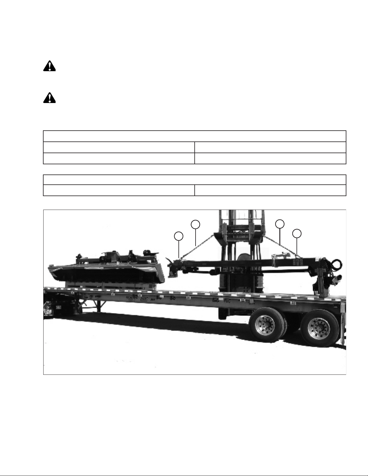
Figure 2.1: Unloading Hitch
B
Chain
A
3630 kg (8000 lb.)
4.5 m (15 ft.)
A
B
1. Remove hauler's tie-down straps and chains.
2. Attach chain (A) to two brackets (B) on top of hitch as shown.
3. Adjust chain lengths so hitch is lifted evenly.
4. Raise hitch off deck, back up until unit clears trailer, and slowly lower to 150 mm (6 in.) from ground.
IMPORTANT:
Take care not to contact the other machine if load is two headers wide.
214713 7 Revision A
1010549
Page 16

UNLOADING TRUCK SHIPMENT
5. Take to storage or assembly area, and set hitch down securely on level ground.
6. Repeat for second hitch (if required).
7. Check for shipping damage and missing parts.
8. Approach disc mower (A) from back with forklift (B) as
shown, and slide forks as far as possible into pallet.
NOTE:
Pallet is designed to be lifted from the backside only.
9. Raise disc mower off deck.
IMPORTANT:
Take care not to contact the other machine if load is
two-wide.
10. Back up until unit clears trailer, and slowly lower to
150 mm (6 in.) from ground.
11. Take to storage or set-up area, and set machine down
securely on level ground.
Figure 2.2: Unloading Disc Mower
NOTE:
When possible, approach from the backside to
minimize potential for contacting the unit.
12. Repeat for second disc mower (if required).
13. Check for shipping damage and missing parts.
IMPORTANT:
Do NOT remove disc mower from pallet until instructed.
14. Unload remaining pallets and boxes, and take to assembly area.
B
A
1015097
214713 8 Revision A
Page 17

Chapter 3: Assembling the Disc Mower (With or Without
1011354
A
B
C
1011500
A
B
the Dealer-Installed Transport)
Perform the following procedures in the order provided to assemble the disc mower without the transport system, or
when the Road Friendly Transport
To assemble a disc mower with the factory-installed transport, refer to 4 Assembling the Disc Mower (Factory-
Installed Transport), page 57.
™
will be installed by the Dealer.
3.1 Repositioning Center-Link Top Anchor
Perform this procedure to reposition the center-link top anchor into working position.
1. Place forklift forks (B) under top beam and lift carrier
frame (A) slightly until pin at base of center-link anchor
is loose. Use a piece of wood (C) to protect paint
on frame.
Figure 3.1: Carrier
2. Loosen jam nut (A) and fully loosen float spring bolt (B).
Repeat on the opposite side.
Figure 3.2: Float Spring
214713 9 Revision A
Page 18

ASSEMBLING THE DISC MOWER (WITH OR WITHOUT THE DEALER-INSTALLED TRANSPORT)
3. Remove four M10 hex head bolts (A) and flat washers,
and remove top shield (B).
CAUTION
To avoid injury, keep fingers clear of opening at base of
anchor.
4. Remove cotter pin (B), washer (C), and shipping
tag (D).
5. Remove pin (A) from center location and lower forks on
forklift.
NOTE:
Pin should slide out freely. Adjust forklift or move carrier
until pin is loose. Do NOT use hammer to remove pin.
B
A
Figure 3.3: Top Shield (Left of Center-Link)
D
A
C
B
1013184
1018340
6. Install pin (A) and secure with washer (B) and cotter
pin (C). Move the carrier and anchor so the pin can be
installed in working location.
Figure 3.4: Center-Link Anchor (Right of
Center-Link)
B
A
C
1018340
Figure 3.5: Center-Link Anchor (Right of
Center-Link)
214713 10 Revision A
Page 19

1013184
A
B
1014709
B
A
C
D
ASSEMBLING THE DISC MOWER (WITH OR WITHOUT THE DEALER-INSTALLED TRANSPORT)
7. Install top shield (B) and secure with four M10 hex head
bolts (A) and flat washers. Torque to 27–30 Nm
(20–22 lbf·ft).
NOTE:
If transport is also being installed, leave bolts (A) loose.
These bolts will be tightened when installing the lighting
harness.
Figure 3.6: Top Shield (Left of Center-Link)
8. Close the disc mower’s lift cylinder lock-out valve (A) on
each lift cylinder by turning the handle to the horizontal
position.
9. Loosen jam nut (B).
10. Turn the adjuster bolt (C) and set dimension (D) to
130 mm (5-1/8 in.).
• Turn bolt clockwise (towards spring) to increase float
• Turn bolt counterclockwise (away from spring) to
decrease float
11. Tighten jam nut (B) against spring.
Figure 3.7: Lift Cylinder Lock-Out Valve, Jam
Nut, and Adjuster Bolt
214713 11 Revision A
Page 20

ASSEMBLING THE DISC MOWER (WITH OR WITHOUT THE DEALER-INSTALLED TRANSPORT)
3.2 Attaching Hitch to Carrier
1. Remove M20 bolts (A), washers, and nuts from carrier
at the hitch attachment location. Retain bolts, washers,
and nuts.
2. Cut banding (A) securing wood supports, then
remove supports (B).
3. Remove the two bolts securing wood support to hitch
pin (C). Discard bolts.
A
1011361
Figure 3.8: Carrier
C
A
4. Place sling (A) around the hitch frame. Adjust sling
position until hitch is balanced when lifting.
• R113: Approximately 2.7 m (106 in.) from the edge
of the tractor end of the hitch (B)
• R116: Approximately 3.5 m (138 in.) from the edge
of the tractor end of the hitch (B)
5. Raise the hitch approximately 610 mm (24 in.) off
the ground.
B
1013890
Figure 3.9: Hitch Packing
B
A
1012287
Figure 3.10: Lifting Hitch
214713 12 Revision A
Page 21

1013891
A
B
C
1011365
A
1015168
A
ASSEMBLING THE DISC MOWER (WITH OR WITHOUT THE DEALER-INSTALLED TRANSPORT)
NOTE:
Hitch pin (C) is heavy. Support it appropriately before
removing bolt (A).
6. Support hitch pin (C), remove bolt (A) and wood
block (B) from top of pin, and remove hitch pin (C).
Figure 3.11: Hitch Packing
7. Install hitch pin (A) fully into hitch.
Figure 3.12: Hitch Pin
8. Pivot the gearbox (A) towards the right side of the
header. This will increase the clearance to the driveline
clutch when installing hitch onto carrier frame.
Figure 3.13: Gearbox
214713 13 Revision A
Page 22

ASSEMBLING THE DISC MOWER (WITH OR WITHOUT THE DEALER-INSTALLED TRANSPORT)
9. Move hitch pivot (A) into attachment location (B) on
carrier, and line up hitch pin with hole in carrier.
A
Figure 3.14: Hitch to Carrier
10. Slowly lower hitch (A) while maintaining pin alignment
until hitch pin (B) is fully inserted. Use a large soft
hammer if necessary to seat hitch pin.
B
B
1011501
11. Line up holes in hitch pin (A) with holes in the carrier
frame. Install six M20 x 65 bolts (B) with hardened
washers under the bolt head and lock nuts (C).
A
1011372
Figure 3.15: Hitch Pin
A
B
C
1011373
Figure 3.16: Hitch Pin
214713 14 Revision A
Page 23

1018594
A
ASSEMBLING THE DISC MOWER (WITH OR WITHOUT THE DEALER-INSTALLED TRANSPORT)
12. Tighten the outer bolts (A) first to draw the plate against
the frame. Then tighten the inner bolts.
13. Torque bolts to 461 Nm (340 lbf·ft).
Figure 3.17: Hitch Pin
214713 15 Revision A
Page 24

ASSEMBLING THE DISC MOWER (WITH OR WITHOUT THE DEALER-INSTALLED TRANSPORT)
3.3 Installing Tractor Mating Hitch to Carrier Hitch
Depending on disc mower configuration, refer to the applicable installation procedure:
• 3.3.1 Installing Drawbar Hitch, page 16
• 3.3.2 Installing Two-Point Hitch (Cat. II) Adapter, page 20
3.3.1 Installing Drawbar Hitch
If attaching the disc mower to a tractor with a drawbar hitch, proceed as follows. If attaching the disc mower to a
tractor with a two-point hitch, refer to 3.3.2 Installing Two-Point Hitch (Cat. II) Adapter, page 20.
1. Remove shipping wire or banding (A) securing shipping
blocks (B) at front of hitch, and remove blocks.
2. Swivel lower gearbox until the input shaft is
facing forward.
3. Remove shipping wire (A) from the jack stand
support (D) and jack (B). Remove the jack stand
support and jack from the pallet. Leave the drawbar
hitch attached to the pallet.
4. Remove the hardware bag from the jack stand support.
A
B
Figure 3.18: Hitch End Packing
D
A
C
Figure 3.19: Jack and Drawbar Hitch Packing
1011296
B
1026323
214713 16 Revision A
Page 25

1026356
A
B
1026352
A
B
1011298
A
B
C
ASSEMBLING THE DISC MOWER (WITH OR WITHOUT THE DEALER-INSTALLED TRANSPORT)
5. Install jack support stand (A) as shown. Secure with two
M12 X 1.75 X 40 bolts (B), M12 washers and M12
center lock nuts per side. Torque hardware to 68.5 Nm
(51 lbf ft)
Figure 3.20: Jack Stand Support
6. Install jack (A) at front of hitch, and secure with pin (B).
7. Lower forklift until hitch is resting on hitch jack (A).
Figure 3.21: Jack Stand
8. Remove shipping wire (A) that secures pin (B) in
casting. Do NOT remove other strapping.
9. Remove pin (B) from casting and remove bolt (C) and
nut from pin.
Figure 3.22: Hitch Casting
214713 17 Revision A
Page 26

ASSEMBLING THE DISC MOWER (WITH OR WITHOUT THE DEALER-INSTALLED TRANSPORT)
10. Using a floor jack or equivalent under pallet (A), raise
drawbar hitch (B) into position under the gearbox.
11. Move drawbar hitch (B) so pin (C) can be installed.
12. Secure pin with bolt (D) and nut.
13. Remove floor jack, and if necessary, remove remaining
strapping and pallet (A) from hitch adapter.
C
D
14. Remove cone shield (A).
15. Retrieve the primary driveline (D) from the shipping
location.
16. Remove nut (C), washer (B) and pin (A) from the disc
mower end of the primary driveline (D).
B
Figure 3.23: Drawbar Hitch
A
Figure 3.24: Cone Shield
A
1026357
1026358
D
A
B
C
Figure 3.25: Primary Driveline
214713 18 Revision A
1023655
Page 27

1026360
A
B
1014852
A
B
C
D
1026361
A
B
ASSEMBLING THE DISC MOWER (WITH OR WITHOUT THE DEALER-INSTALLED TRANSPORT)
17. Slide the primary driveline (A) onto the gearbox input
shaft. Align the pinhole (B) in the yoke with the groove
on the input shaft.
Figure 3.26: Primary Driveline
18. Insert tapered pin (A) by hand. Ensure the pin lines up
with groove in yoke and is fully inserted. The notch in
the pin should be facing toward the shaft.
19. Clean the threads on pin (A) after it has been inserted.
20. Install washer (B) and nut (C) on tapered pin and torque
to 149 Nm (110 lbf·ft). The end of the pin must be
recessed approximately 9–11 mm (0.35–0.43 in.) (D).
NOTE:
Do NOT use an impact wrench to install or torque
the nut.
Figure 3.27: Primary Driveline
21. Install the cone shield (A) over the primary driveline (B).
Use the latches to secure it to the gearbox.
22. Place the primary driveline (B) on the driveline support.
23. Install hitch swing cylinder. Refer to 3.4 Installing Hitch
Swing Cylinder, page 24.
Figure 3.28: Cone Shield
214713 19 Revision A
Page 28

ASSEMBLING THE DISC MOWER (WITH OR WITHOUT THE DEALER-INSTALLED TRANSPORT)
3.3.2 Installing Two-Point Hitch (Cat. II) Adapter
1. Remove shipping wire or banding (A) securing shipping
blocks (B) at front of hitch, and remove blocks.
2. Swivel lower gearbox until the input shaft is
facing forward.
3. Retrieve two-point hitch adapter shipment.
4. Remove shipping wire (A) and material from stand (B),
and remove stand from hitch adapter (C).
5. Remove strapping that secures pin (A) to adapter (B).
Do NOT remove other strapping.
6. Remove pin (A) from adapter, and remove bolt (C) and
nut from pin (A).
A
B
1011296
Figure 3.29: Hitch Packing
B
A
C
1011306
Figure 3.30: Two-Point Hitch Packing
A
B
C
Figure 3.31: Two-Point Hitch Adapter
214713 20 Revision A
1011311
Page 29

1023634
A
B
C
D
1023633
A
B
C
1023642
A
B
ASSEMBLING THE DISC MOWER (WITH OR WITHOUT THE DEALER-INSTALLED TRANSPORT)
7. Using a floor jack or equivalent, raise two-point hitch
adapter (A) into position under the gearbox.
8. Maneuver adapter (A) so that pin (B) can be installed to
secure adapter to hitch.
9. Secure pin with bolt (C) and nut (D).
10. Remove floor jack, and remove remaining strapping
and pallet from hitch adapter.
Figure 3.32: Two-Point Hitch Adapter
11. Retrieve stand (A).
12. Position stand (A) under gearbox as shown, and install
hitch pin (B) to secure the stand.
13. Install hairpins (C) to secure hitch pin (B).
14. Lower hitch and stand to the ground.
15. Install springs (A) into hooks (B). Repeat on
opposite side.
Figure 3.33: Stand
Figure 3.34: Springs
214713 21 Revision A
Page 30
ASSEMBLING THE DISC MOWER (WITH OR WITHOUT THE DEALER-INSTALLED TRANSPORT)
16. Remove cone shield (A).
A
Figure 3.35: Cone Shield
17. Retrieve the primary driveline (D) from the shipping
location.
D
18. Remove nut (C), washer (B), and pin (A) from the disc
mower end of primary driveline (D).
1026370
A
19. Slide driveline (A) onto gearbox input shaft (B). Align
the pinhole in the yoke with the groove on the
input shaft.
B
C
1023655
Figure 3.36: Primary Driveline
B
A
1026375
Figure 3.37: Primary Driveline
214713 22 Revision A
Page 31

1014852
A
B
C
D
1026376
A
B
ASSEMBLING THE DISC MOWER (WITH OR WITHOUT THE DEALER-INSTALLED TRANSPORT)
20. Insert tapered pin (A) by hand. Ensure the pin lines up
with groove in the yoke and is fully inserted. The notch
in the pin should be facing toward the shaft.
21. Clean the threads on pin (A) after it has been inserted.
22. Install washer (B) and nut (C) on the tapered pin and
torque to 149 Nm (110 lbf·ft). The end of the pin must
be recessed 9–11 mm (0.35–0.43 in.) (D).
NOTE:
Do NOT use an impact wrench to install or torque
the nut.
Figure 3.38: Primary Driveline
23. Install cone shield (A) over the primary driveline. Place
driveline (B) on the driveline support.
Figure 3.39: Cone Shield
214713 23 Revision A
Page 32

ASSEMBLING THE DISC MOWER (WITH OR WITHOUT THE DEALER-INSTALLED TRANSPORT)
3.4 Installing Hitch Swing Cylinder
The hitch swing cylinder can be installed on either side of the hitch, depending on whether or not the Road Friendly
Transport
™
system will be installed. Be sure to follow the instructions carefully.
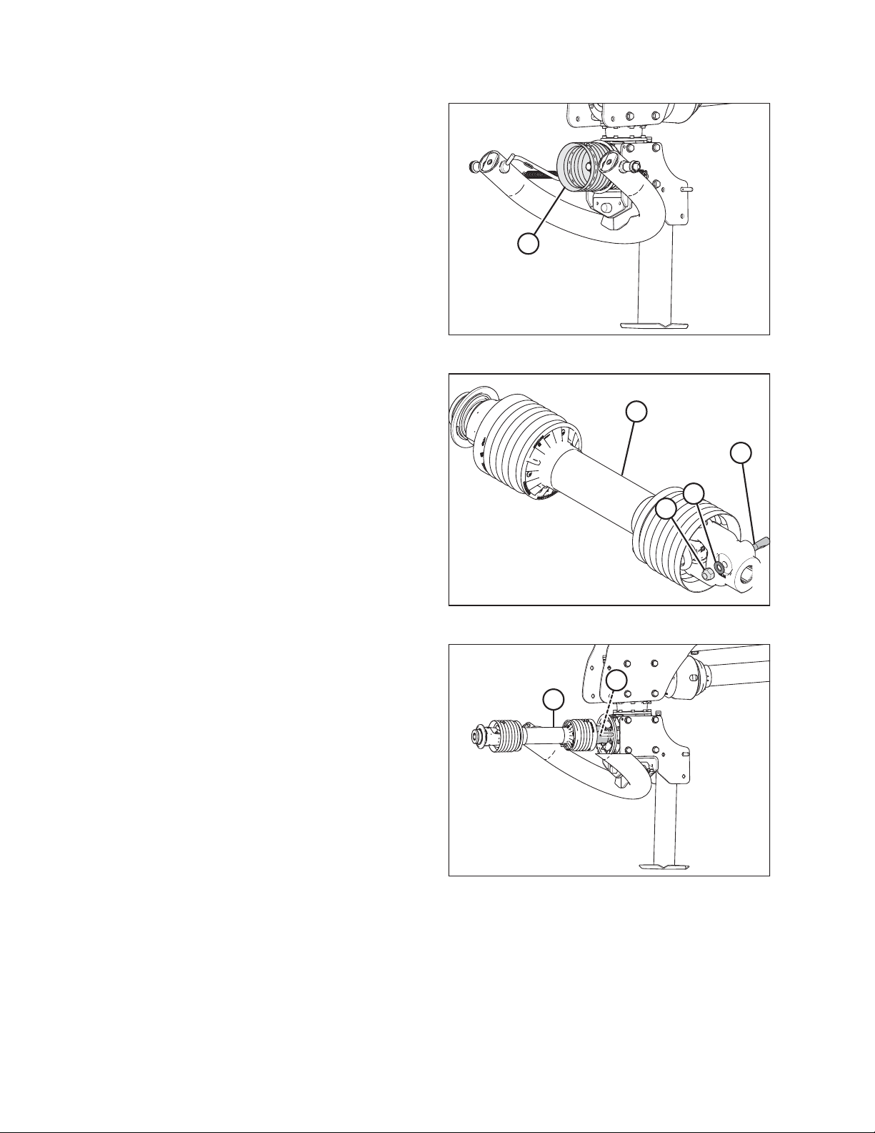
1. Remove the banding (A) securing the hitch swing
cylinder (B) to the hitch.
2. Remove pin (C) securing cylinder (B) to hitch.
A
C
B
Figure 3.40: Steering Cylinder
To install cylinder on unit WITHOUT the Road Friendly Transport
™™
system, proceed as follows:
1. Reposition cylinder (A) at left side of hitch and attach
rod end to carrier frame lug with pin at location (B).
Secure with cotter pin (C).
2. Place a container or rag under the cylinder to catch oil.
3. Remove pin from location (D) at the clevis end of the
cylinder.
D
A
1011322
4. Swing the hitch until clevis lines up with lug on hitch.
5. Install clevis pin at location (D) and secure with cotter
pin (E).
NOTE:
Loosen the hydraulic fittings, if assistance is required to align
the clevis and lug.
6. If loosened, tighten the fittings on cylinder.
E
C
Figure 3.41: Hitch Swing Cylinder
B
1013472
214713 24 Revision A
Page 33

1011502
A
B
C
D
ASSEMBLING THE DISC MOWER (WITH OR WITHOUT THE DEALER-INSTALLED TRANSPORT)
To install cylinder on unit WITH the Road Friendly Transport™™system, proceed as follows:
1. Disconnect the hoses from the cylinder and cap off
openings on cylinder and hoses.
2. Reposition cylinder (A) at right side of hitch. Use pin (C)
to attach barrel end to lug (B). Secure with cotter
pin (D).
NOTE:
The clevis end of cylinder will be attached to the Road
Friendly Transport
™
system casting after the system is
primed. Refer to 5.5 Priming the Hitch Swing Cylinder,
page 102.
3. Turn the valve on the hitch swing cylinder 180 degrees,
so that fittings are pointing up.
Figure 3.42: Hitch Swing Cylinder
214713 25 Revision A
Page 34

ASSEMBLING THE DISC MOWER (WITH OR WITHOUT THE DEALER-INSTALLED TRANSPORT)
3.5 Attaching Clutch Driveline
This procedure describes how to attach the clutch driveline to the header drive gearbox.
IMPORTANT:
If a conditioner swap is required before delivery to the customer, do NOT perform this step at this time. Skip to 5.4
Installing Field Wheels, page 100 and then return to this topic to complete the setup.
1. Support driveline (B) and remove strapping (A) securing
it to hitch. Remove all packing material.
A
B
Figure 3.43: Driveline Strapping
1011377
2. Remove strapping (A) and packing material securing
steering arm (B) to hitch. Pivot steering arm to the side
for now.
NOTE:
Strapped contents may be under pressure.
3. At the top of the upper rear swivel gearbox, remove two
bolts (A) with spacers (B). Retain hardware.
4. Undo latches (C) securing driveline shield (D) to the
upper rear swivel gearbox and remove the shield. If
necessary, use a screwdriver or equivalent to undo
latches (C).
5. Rotate the upper rear swivel gearbox until the input
shaft is facing towards the driveline.
A
B
Figure 3.44: Steering Arm Strapping
B
D
1011397
A
C
Figure 3.45: Driveline Shield
214713 26 Revision A
1015161
Page 35

1011385
A
B
C
D
E
1015164
A
1014852
A
B
C
D
ASSEMBLING THE DISC MOWER (WITH OR WITHOUT THE DEALER-INSTALLED TRANSPORT)
6. Slide cone (A) onto driveline with latches (B) towards
the gearbox.
7. Remove nut (C) and washer (E) from tapered pin (D),
and tap out pin from yoke using a hammer.
Figure 3.46: Clutch Driveline
8. Attach driveline (A) to the upper rear swivel
gearbox shaft.
Figure 3.47: Clutch Driveline
9. Insert tapered pin (A) by hand. Ensure the pin lines up
with groove in the yoke and is fully inserted. The notch
in the pin should be facing toward the shaft.
10. Clean the threads on pin (A) after it has been inserted.
11. Install washer (B) and nut (C) on the tapered pin, and
then torque to 149 Nm (110 lbf·ft). The end of the pin
must be recessed 0–2mm(0–0.08 in.) (D).
NOTE:
Do NOT use an impact wrench to install or torque
the nut.
12. Install the shield onto the upper rear swivel gearbox.
Use the latches to secure it.
Figure 3.48: Clutch Driveline
214713 27 Revision A
Page 36

ASSEMBLING THE DISC MOWER (WITH OR WITHOUT THE DEALER-INSTALLED TRANSPORT)
3.6 Attaching Steering Arm
This procedure describes how to attach the steering arm to the header drive gearbox.
IMPORTANT:
If a conditioner swap is required before delivery to the customer, do NOT perform this step at this time. Skip to 5.4
Installing Field Wheels, page 100 and then return to this topic to complete the setup.
1. Lower arm (A) from under the hitch and slide the
steering arm (B) off the support tube.
2. Apply grease to arm (A).
3. Slide steering arm (C) onto the support tube (A) in the
opposite direction.
4. Position steering arm (C) onto gearbox (D).
A
B
5. Line up the two mounting holes in arm weldment with
the forward threaded holes in the upper rear swivel
gearbox.
6. Install spacers (A) into steering arm (B).
7. Install washer (D), onto the M16 x 80 hex head
bolts (C). Install high-strength threadlocker (Loctite
®
262 or equivalent) onto the bolt threads.
8. Torque bolts to 203 Nm (150 lbf·ft).
C
D
Figure 3.49: Steering Arm
A
C
D
Figure 3.50: Steering Arm
A
1011400
B
1011402
214713 28 Revision A
Page 37

1014331
A
ASSEMBLING THE DISC MOWER (WITH OR WITHOUT THE DEALER-INSTALLED TRANSPORT)
9. Attach safety chain (A) from driveline shield to slotted
hole in the steering arm.
NOTE:
Ensure chain is shortened to prevent any driveline
wrapping.
Figure 3.51: Driveline Shield
214713 29 Revision A
Page 38

ASSEMBLING THE DISC MOWER (WITH OR WITHOUT THE DEALER-INSTALLED TRANSPORT)
3.7 Connecting Transport Lighting Module
1. Locate plugs P102 on trailer harness (A) at the header
end of the hitch. Route plug P102 towards the transport
lighting module.
2. Connect plug P102 (B) to the upper input receptacle on
the transport lighting module (C).
Figure 3.52: Trailer Harness
A
C
B
1025979
214713 30 Revision A
Page 39

1014333
A
B
C
1022720
A
B
ASSEMBLING THE DISC MOWER (WITH OR WITHOUT THE DEALER-INSTALLED TRANSPORT)
3.8 Installing Options
Install the following optional kits if they were supplied with your disc mower.
3.8.1 Installing Road Friendly Transport™™System
This section explains how to install the Road Friendly Transport™system (C2002). The basic components are
installed first, then the hydraulic systems, and then lighting and signage.
Installing Components
This section explains how to install the basic parts of the Road Friendly Transport™System.
Installing Latch Assembly
1. Disconnect right light electrical connection (A).
2. Remove the two bolts (B) that secure right light
assembly (C) to the carrier frame.
3. Remove light assembly (C). Retain the light assembly
and hardware for installation later.
4. On the transport pallet, remove the shipping banding
and packing material from latch assembly (A). Remove
the latch assembly.
5. Remove the two M20 mounting bolts, washers, and
nuts (B) from the latch assembly, and retain for
use later.
Figure 3.53: Light Bracket
Figure 3.54: Latch Packing
214713 31 Revision A
Page 40

ASSEMBLING THE DISC MOWER (WITH OR WITHOUT THE DEALER-INSTALLED TRANSPORT)
6. Install latch assembly (A) onto the carrier frame as
shown, and secure with the M20 bolts, washers, and
nuts (B) retained in Step 5, page 31.DoNOT fully
A
tighten bolts; adjustment of the latch assembly may be
necessary.
B
Figure 3.55: Latch Assembly
7. Loosen fitting (A) on the cylinder lockout valve.
8. Remove elbow fitting (B) from the cylinder.
1011183
9. Install tee fitting (A) in place of the elbow fitting.
10. Install cylinder lockout valve (B) on tee fitting (A)
as shown.
11. Attach hydraulic hose (C) from the latch assembly to
tee fitting (A) as shown.
A
B
1023770
Figure 3.56: Latch Plumbing
B
C
A
1023769
Figure 3.57: Latch Plumbing
214713 32 Revision A
Page 41

A
B
ASSEMBLING THE DISC MOWER (WITH OR WITHOUT THE DEALER-INSTALLED TRANSPORT)
12. Retrieve clevis pin (A) and cotter pin (B) from the
shipping bag and install onto the hitch bracket at the
side of the hitch.
Figure 3.58: Latch Pin
214713 33 Revision A
Page 42

ASSEMBLING THE DISC MOWER (WITH OR WITHOUT THE DEALER-INSTALLED TRANSPORT)
Installing Transport Assembly
1. Remove two bolts (A), hardened washer, and nut
securing slow moving vehicle (SMV) sign (B) to the
carrier frame, and remove sign. Retain sign and
hardware for reinstallation.
B
Figure 3.59: SMV Sign Attached to
Carrier Frame
2. Remove transport wheels (A) from the pallet.
A
1025984
3. Remove the five M20 hex head bolts (B), washers, and
nuts in transport assembly pin (C). Do NOT remove pin.
4. Using a forklift, pick up the pallet holding the transport
assembly (A) and align it with the rear of the
disc mower.
5. Position the assembly close behind the frame and align
pin (B) in transport assembly with hole (C) in the carrier.
Use a soft hammer or equivalent to fully insert pin (B).
B
A
C
1022722
Figure 3.60: Transport Packing
B
C
A
Figure 3.61: Road Friendly Transport
214713 34 Revision A
™™
1011186
Page 43

1022604
A
B
1026195
A
B
C
D
1022611
A
B
ASSEMBLING THE DISC MOWER (WITH OR WITHOUT THE DEALER-INSTALLED TRANSPORT)
6. Install two M20 x 65 bolts (A), hardened washers,
and nuts.
7. Temporarily install bolts (B) to help align the assembly.
Figure 3.62: Pin Support
8. Rotate pin (A), until hole in pin aligns with holes in
welded collar (B). Insert pin (C) (MD #19958) through
the collar and pin.
9. Insert cotter pin (D) (MD #18608) and bend over the
legs to secure it.
Figure 3.63: Pin Installation
10. Retrieve cover assembly (B) from the shipping location.
11. Remove two bolts (A) from the cover assembly (B).
Retain bolts and cover for installation later.
Figure 3.64: Cover Assembly
214713 35 Revision A
Page 44

ASSEMBLING THE DISC MOWER (WITH OR WITHOUT THE DEALER-INSTALLED TRANSPORT)
12. Install cover support (B).
13. Secure cover support (B) in place with one M20 x 65
bolt (A), hardened washer, and nut.
14. Torque bolts (A) to 461 Nm (340 lbf·ft).
15. Remove and retain bolts (B).
B
A
Figure 3.65: Cover Support
Figure 3.66: Cover Support
1022605
A
B
1022606
Installing Transport Valve
NOTE:
Cover support bracket removed from illustrations for clarity.
1. Retrieve valve assembly (A) from the pallet.
2. Position valve assembly (A) on the carrier hitch pin
plate as shown.
3. Install two M20 x 65 bolts (B), hardened washers,
and nuts.
4. Retrieve two M10 x 20 bolts from the shipping bag and
install bolts at location (C) with threads facing up. Install
nuts, but do not tighten.
5. Torque bolts (B) to 461 Nm (340 lbf·ft).
B
C
A
1016394
Figure 3.67: Selector Valve
214713 36 Revision A
Page 45

1022693
A
B
D
C
1014868
A
C
B
1014950
A
B
C
D
ASSEMBLING THE DISC MOWER (WITH OR WITHOUT THE DEALER-INSTALLED TRANSPORT)
6. Disconnect plugs P102 (A) and P301 (B) from the
transport lighting module.
7. Remove bolts (C) and remove the transport lighting
module, complete with support bracket (D).
Figure 3.68: Lightening Module Harness
8. Install support plate (A) and secure it with bolts (B).
9. Install bolts (C), but do NOT tighten.
Figure 3.69: Support Plate
10. Remove nut (A) from support (D).
11. Install bolt (B) through support (D) and support (C), and
then reinstall nut (A).
Figure 3.70: Support Plate
214713 37 Revision A
Page 46

ASSEMBLING THE DISC MOWER (WITH OR WITHOUT THE DEALER-INSTALLED TRANSPORT)
Installing Transport Swing Cylinder
1. Remove the shipping bag from the pallet.
2. Retrieve the clevis pin from the shipping bag.
3. Support transport swing cylinder (A). Cut straps
securing the cylinder to the pallet.
A
Figure 3.71: Transport Swing Cylinder
IMPORTANT:
Transport swing cylinder (A) must be primed before
installing it on the carrier frame.
B
4. To prime the cylinder, use a hydraulic power pack or
tractor hydraulics. Extend and retract transport swing
cylinder (A) until all the air has been removed. Extend
transport cylinder (A) to 142 cm (56 in.) between center
of pins.
A
1014867
C
NOTE:
If you need to adjust the cylinder length, remove bolt (C)
that secures the clevis end. Rotate the clevis to
lengthen or shorten the distance between pins (B).
When the cylinder length is correct, reinstall bolt (C) to
secure the clevis end.
5. Install barrel end of the transport swing cylinder (A) onto
the carrier frame with clevis pin (B). Secure clevis pin
with cotter pin (C).
Figure 3.72: Transport Swing Cylinder
B
C
A
Figure 3.73: Transport Swing Cylinder
1016379
1014869
214713 38 Revision A
Page 47

1014871
A
B
C
D
1011190
A
B
1015155
A
B
ASSEMBLING THE DISC MOWER (WITH OR WITHOUT THE DEALER-INSTALLED TRANSPORT)
6. Connect clevis end (B) of the transport swing
cylinder (A) to transport casting. Align holes and install
clevis pin (C). Secure with cotter pin (D).
Figure 3.74: Swing Cylinder (Rear Left View)
Installing Transport Wheels
1. Cut the straps securing the transport assembly to the
pallet.
2. Slowly lower forklift until transport assembly wheel
spindles (A) are approximately 305 mm (12 in.) off
the ground.
3. Remove wheel bolts (B) from spindle hub (A) on the
left side.
4. Remove bolt (B) holding axle assembly (A) in place.
5. Slide axle assembly (A) out of the support.
Figure 3.75: Transport Wheel
Figure 3.76: Axle Assembly Relocation
214713 39 Revision A
Page 48

ASSEMBLING THE DISC MOWER (WITH OR WITHOUT THE DEALER-INSTALLED TRANSPORT)
6. Install axle assembly (A) into the support.
7. Install bolt (B) with nut, and torque to 68 Nm (50 lbf·ft).
8. Remove the wheel bolts from hub (A).
CAUTION
When installing wheel, be sure to match countersunk
holes with bolt head profiles. Holes that are not
countersunk do NOT correctly seat the bolts.
B
Figure 3.77: Axle Assembly Relocation
9. Retrieve the transport wheels and install with the wheel
bolts. Ensure the valve stem faces outboard. Do NOT
fully tighten bolts.
10. Lower wheels to the ground and back forklift away.
1
11. Torque wheel bolts to 160 Nm (120 lbf·ft) following the
tightening sequence shown.
3
A
1015156
5
NOTE:
Whenever a wheel is installed, check torque after one
hour of operation.
12. Check tire pressure and adjust as required. Refer to 7.2
Checking Tire Pressure, page 128.
Installing Transport Alignment Control
1. Remove cam assembly (A) from shipping support (B).
2. Remove nuts (C) from the cam assembly.
6
4
Figure 3.78: Tightening Sequence
A
2
1015147
C
B
1014884
Figure 3.79: Alignment Controls (Front
Right View)
214713 40 Revision A
Page 49

1014876
A
C
B
1014886
A
B
1014334
A
B
C
ASSEMBLING THE DISC MOWER (WITH OR WITHOUT THE DEALER-INSTALLED TRANSPORT)
3. Secure cam assembly (A) onto hitch swing cylinder
plate (B) with bolts and nuts (C). Torque nuts (C) to
55–60 Nm (40–45 lbf·ft).
NOTE:
When installing cam assembly (A), check for hose
twisting. If required, loosen hose fitting to allow hose to
untwist. Torque fitting when complete.
Figure 3.80: Alignment Control (Rear
Right View)
4. Remove two bolts (B), then remove shipping
support (A) and discard.
Figure 3.81: Shipping Support (Front
Right View)
5. Check the travel of cam arm (A) by sliding it in and out
of cam assembly (B).
NOTE:
If the cam arm does not slide easily, loosen valve
mounting bolts (C) and position valve (B) at the top of
the mounting holes. Retighten valve mounting bolts (C).
Figure 3.82: Alignment Control (Rear
Right View)
214713 41 Revision A
Page 50

ASSEMBLING THE DISC MOWER (WITH OR WITHOUT THE DEALER-INSTALLED TRANSPORT)
6. Align the hole in cam arm (A) with the hole in cylinder
clevis (B).
Figure 3.83: Alignment Control (Rear
Right View)
7. Ensure the end of cam arm (A) is parallel with the clevis
end (B) of the cylinder. If adjustment is required, use a
bar to turn the clevis until the clevis is parallel with
cam arm (A).
NOTE:
The clevis end of the cylinder will be attached to the
™
Road Friendly Transport
casting when the system
is primed. Refer to 5.5 Priming the Hitch Swing
Cylinder, page 102.
A
B
1014337
A
B
Figure 3.84: Cam Arm Alignment
214713 42 Revision A
1014336
Page 51

1014877
A
B
C
1014882
A
B
C
ASSEMBLING THE DISC MOWER (WITH OR WITHOUT THE DEALER-INSTALLED TRANSPORT)
8. Retrieve completion valve assembly (A) and one
M12 x 25 flanged hex head bolt from the shipping bag.
9. Remove bolts (B) from the standoffs on rear of carrier.
Install valve assembly (A) behind support plate (C).
Secure it to the standoffs using the three M12 x 25
flanged hex head bolts (B).
Figure 3.85: Control Valve
10. Retrieve paddle assembly (B) from the shipping bag.
11. Install washers (A) onto the bolts welded to the
completion valve assembly.
12. Install paddle assembly (B) onto the welded bolts and
secure with nuts (C).
NOTE:
Make sure that paddle (B) is centered on the valve and
moves freely.
Figure 3.86: Control Valve
214713 43 Revision A
Page 52

ASSEMBLING THE DISC MOWER (WITH OR WITHOUT THE DEALER-INSTALLED TRANSPORT)
Installing Hydraulics
This section explains how to install the transport hydraulic control system.
Installing Hydraulic Lines and Hoses
NOTE:
Cover support bracket removed from illustrations for clarity.
NOTE:
Refer to 11.6 Torque Specifications, page 208 for hydraulic fitting installation details.
1. Retrieve steel lines and hoses from shipping bag.
2. Place a container or rag under the fitting on the hitch
swing cylinder.
3. Remove existing fitting (A) from the block.
4. Remove the cap from tee fitting (C).
5. Retrieve ORFS-6 x ORB-6 connector (B) from shipping
bag and install at location (A).
NOTE:
Ensure that the direction arrow on check valve (D)
points away from tee fitting (C).
6. Remove the cap from fitting (A).
7. Remove the plug from hose (B). Install hose to
fitting (A) as shown.
D
C
B
A
1018408
Figure 3.87: Alignment Valve Fitting
B
A
Figure 3.88: Alignment Valve Fitting
214713 44 Revision A
1014896
Page 53

1023782
A
B
C
D
1024973
A
B
C
ASSEMBLING THE DISC MOWER (WITH OR WITHOUT THE DEALER-INSTALLED TRANSPORT)
8. Install steel line (A) from port A on the completion
assembly to tee fitting (D).
9. Install steel line (B) from port B on the completion
assembly to tee fitting (C).
Figure 3.89: Completion Assembly Plumbing
10. Attach hose (A) to steel line connecting to port C of
transport swing control.
11. Attach hose (B) to steel line connecting to port D of
transport swing control.
12. Secure hoses (A) and (B) together with cable tie.
NOTE:
Ensure that direction arrow on check valve (C) points
toward tee fitting.
Figure 3.90: Transport Swing Cylinder
214713 45 Revision A
Page 54

ASSEMBLING THE DISC MOWER (WITH OR WITHOUT THE DEALER-INSTALLED TRANSPORT)
13. Install hose (A) from outer port (rod end) on transport
cylinder block to tee fitting (D) in port D of transport
swing control.
14. Install hose (B) from inner port (base end) on transport
cylinder block to tee fitting (C) in port C of transport
swing control.
A
B
D
C
Figure 3.91: Transport Swing Control
1014929
15. Connect hose (B) with red collar #2, from the rear of the
hitch, to fitting in port A1 on selector valve (C).
16. Connect hose (A) with blue collar #2, from the rear of
the hitch, to fitting in port A2 of the selector valve (C).
17. Secure hoses (A) and (B) together with cable tie.
B
A
C
1022691
Figure 3.92: Selector Valve Supply
214713 46 Revision A
Page 55

1014903
A
B
C
1014913
A
B
C
D
E
A
ASSEMBLING THE DISC MOWER (WITH OR WITHOUT THE DEALER-INSTALLED TRANSPORT)
Installing secondary lift hose for field wheels
NOTE:
The secondary lift hose is required to lift the field wheels fully into storage position when the disc mower is in
transport mode.
Retrieve the following secondary lift hose from the shipping bag according to your disc mower size:
• 4.0 m (13 ft.) headers: Use hose MD #224160.
• 4.9 m (16 ft.) headers: Use hose MD #224162.
18. Retrieve the blue collars with the number one (blue
collar #1) on them from the shipping bag. Place one
collar on each end of the secondary lift hose (B).
19. Undo adjustable strap (A) around hoses at aft end
of hitch.
20. Locate the green wire preinstalled in the hitch for pulling
hoses through the hitch.
NOTE:
If you are installing a hydraulic center-link, pull the
hydraulic hoses through the hitch at the same time as
the lift hose.
21. At rear of hitch, feed male ORB end of hose (B) into
access hole (C). Route hose through the hitch to the
opening at front.
22. Position long hose (A) so that the exposed length at the
front of hitch matches existing hose (B). Route hose
through guide (C).
23. At front of hitch, loosen nut (D) on hose clamp (E) until
hose (A) can be positioned in clamp.
24. Tighten nut (D).
Figure 3.93: Lift Hoses
Figure 3.94: Lift Hoses
214713 47 Revision A
Page 56

ASSEMBLING THE DISC MOWER (WITH OR WITHOUT THE DEALER-INSTALLED TRANSPORT)
25. Retrieve ORB-8 coupler (A) and plastic cap (B) from the
hardware bag.
26. At forward end of hitch, install coupling (A) and plastic
A
cap (B) onto secondary lift hose (C). Do NOT attach
hoses to tractor at this time.
B
Figure 3.95: Lift Hose Fittings
27. At rear of hitch, secure the hoses with adjustable
strap (A).
A
C
1016548
Figure 3.96: Lift Hoses
1022602
214713 48 Revision A
Page 57

1022603
A
B
C
D
E
1011227
A
B
C
ASSEMBLING THE DISC MOWER (WITH OR WITHOUT THE DEALER-INSTALLED TRANSPORT)
28. Route hose (A) through opening (E) at the rear of
the frame.
29. Feed shortest hose (A) through opening (B) in carrier
frame as shown with male end (C) at the hitch pivot.
30. Connect hose (A) (MD #247106) and hose (D)
(MD #224160 or MD #224162) at the hitch pivot.
31. Retrieve ORFS-6 x ORB-8 elbow from the
hardware bag.
32. Remove plug at base of lift cylinder and install elbow (A)
as shown.
33. Connect hose (B) to elbow and tighten.
34. Tighten remaining connections.
35. Secure hose to cylinder with cable tie (C).
Figure 3.97: Lift Hose
Figure 3.98: Lift Cylinder
214713 49 Revision A
Page 58

ASSEMBLING THE DISC MOWER (WITH OR WITHOUT THE DEALER-INSTALLED TRANSPORT)
Installing Electrical Components
Installing Light Assemblies
1. Disconnect the wiring harnesses at the left light
assembly; there are two connectors per assembly.
2. Remove the left light assembly (A).
NOTE:
Right side was removed earlier.
3. Remove red lamp (C) from the right light assembly
(removed in an earlier procedure). Align red lamp (C)
with the predrilled holes, in the left lamp bracket, next to
amber lamp. Secure the red lamp with
existing hardware, as shown.
4. Install right light assembly (A) on the left float spring
mount using bolts (B) removed in Step 2, page 50. Red
lamp (C) should be towards rear of machine when in
transport mode.
A
1015032
Figure 3.99: Transport Lighting
C
B
A
5. Retrieve new light bracket (C) from shipment.
6. Install amber lamp (A) and red lamp (B) onto new
bracket (C), previously removed from the right lamp
bracket, with hardware provided.
1015039
Figure 3.100: Left Side of Carrier
B
A
C
1011253
Figure 3.101: Light Assembly
214713 50 Revision A
Page 59

1011254
A
B
1022674
A
B
C
D
1022676
A
B
C
D
E
ASSEMBLING THE DISC MOWER (WITH OR WITHOUT THE DEALER-INSTALLED TRANSPORT)
7. Install light assembly (A) onto header left end with two
M10 x 20 carriage bolts (B) and lock nuts from the
shipping bag. Ensure the amber lamp faces the front of
header and reflector faces outboard.
Figure 3.102: Header Left Side Lighting
Installing Left Side Transport Harness
1. Retrieve transport harness (A) (MD #281614) from the
shipping bag.
2. Route connectors P201 and P202 on the end of
harness (A) to cover support (D).
3. Using a draw tape or equivalent, route connectors P401
and P404 on the other end of the harness (A) through
opening (B) at front of carrier to opening (C) adjacent to
center-link.
4. Route the harness until the plugs reach the left light
assembly on the header.
5. Locate plug P301 (D) on harness (E) (MD #281613). It
was disconnected from the old lighting module.
6. Connect plug P201 (B) on harness (A) (MD #281614)
into the lower output receptacle on the lighting module.
7. Connect plug P301 (D) to receptacle P202 (C).
Figure 3.103: Harness Routing
Figure 3.104: Harness Connection
214713 51 Revision A
Page 60

ASSEMBLING THE DISC MOWER (WITH OR WITHOUT THE DEALER-INSTALLED TRANSPORT)
8. Route harness (A) to light (B) on header as shown.
9. Retrieve p-clips, plastic clamps, and cable ties from
shipping bag.
10. Remove bolts (C) on header at locations shown.
11. Secure harness (A) with p-clips, existing bolts (C), and
plastic clamp (D) into existing holes.
NOTE:
4.0 m (13 ft.) header: Harness for disc mower is
secured with one plastic clamp (D).
NOTE:
4.9 m (16 ft.) header: Harness for disc mower is
secured with two plastic clamps (D).
12. Secure harness (A) to light bracket with two
cable ties (E).
13. Push excess harness into carrier frame.
14. Connect plug P401 and P404 into the light (B).
Connecting Right Side Transport Harness
1. Route transport harness (A) from opening into light
bracket (B) and plug into light connectors.
2. Secure harness (A) to light bracket with two cable
ties (C).
A
C
D
B
E
Figure 3.105: Harness Routing – R113 Shown
(R116 Similar)
1014366
3. Push excess harness into carrier frame.
B
C
A
Figure 3.106: Transport Light
1011292
214713 52 Revision A
Page 61

1022681
A
B
C
D
1015230
A
1015231
A
B
C
ASSEMBLING THE DISC MOWER (WITH OR WITHOUT THE DEALER-INSTALLED TRANSPORT)
Connecting Selector Valve and Transport Lighting Module
1. Locate plugs P102 (A) and P502 (B) on the transport
harness at the header end of the hitch. Route plugs
P102 (A) and P502 (B) towards selector valve (C).
2. Connect plug P502 (B) to the receptacle on selector
valve (C).
3. Connect plug P102 (A) to the upper input receptacle on
transport lighting module (D).
Figure 3.107: Selector Valve Supply
Installing Remote Control
1. Retrieve remote control (A) with wiring harness.
2. Place remote control (A) on hitch temporarily.
3. Locate connector (C) that branches off the seven-pole
transport plug (A) and attach it to the remote wiring
harness (B).
Figure 3.108: Remote Control on Top of Hitch
Figure 3.109: Transport Harness
214713 53 Revision A
Page 62

ASSEMBLING THE DISC MOWER (WITH OR WITHOUT THE DEALER-INSTALLED TRANSPORT)
4. If your tractor has a three-pin auxiliary power
connection:
NOTE:
The remote control has internal protection which
prevents damage caused by incorrect wiring, short
circuits, or overload conditions.
A
Connect two wires (B) from the three-pin auxiliary
connector (A) to the remote control wires (C) on the
remote control, wrap connections with electrical tape,
and proceed to Step 6, page 54.
C
• The wire with no tag connects to the tractor ground.
• The wire with the red tag connects to the
tractor power.
Figure 3.110: Three-Pin Auxiliary Connector
NOTE:
If connections are reversed, the lamp will not illuminate when the toggle switch is in field mode. Try the
following to correct the issue:
• Check internal fuse may have blown.
B
10236931023693
• Check for short in wires to solenoid valve on header.
• Check for incorrect wire connections (reversed) at the power supply or solenoid valve.
If your tractor does NOT have a three-pin auxiliary
power connection:
NOTE:
The remote control has internal protection which
prevents damage caused by incorrect wiring, short
circuits, or overload conditions.
5. Connect remote control wires (A) to the tractor’s power
supply:
• Connect wire (B) with no tag to tractor ground.
• Connect wire (C) with the red tag to tractor power.
NOTE:
If the red tag is missing, identify the power by locating
the wire with the number 1 printed on it. The ground
B
wire has a number 2 printed on it.
NOTE:
If connections are reversed, the lamp will not illuminate
C
when the toggle switch is in field mode. Try the
following to correct the issue:
A
1023703
• Check internal fuse may have blown.
Figure 3.111: Remote Control
• Check for short in wires to solenoid valve on header.
• Check for incorrect wire connections (reversed) at
the power supply or solenoid valve.
6. Place the remote control inside the tractor cab.
214713 54 Revision A
Page 63

1025989
B
A
1025993
A
C
B
D
1026208
A
B
C
D
ASSEMBLING THE DISC MOWER (WITH OR WITHOUT THE DEALER-INSTALLED TRANSPORT)
Installing Slow Moving Vehicle (SMV) Sign
1. Retrieve SMV sign that was previously removed.
2. Remove bolts (A), and discard existing bracket (B).
Retain the bolts and nuts.
Figure 3.112: SMV Sign
3. Retrieve bracket (A).
4. Attach bracket (A) to left end float spring member with
M12 bolts (B) and nuts retained from earlier step.
5. Attach sign (C) to bracket (A) and secure with two
nuts (D) and bolts.
6. Remove decal bag (B) taped to the SMV bracket (A).
7. Choose the appropriate speed decal (C) or (D)
depending on region. Orient decal as shown when
installing it on the SMV bracket.
Figure 3.113: SMV Sign
214713 55 Revision A
Figure 3.114: SMV Decals
Page 64

ASSEMBLING THE DISC MOWER (WITH OR WITHOUT THE DEALER-INSTALLED TRANSPORT)
Installing Cover
1. Install cover (A) onto the cover support.
2. Install bolts (B). Torque to 55–65 Nm (41–48 lbf·ft).
A
B
Figure 3.115: Cover
3.8.2 Installing Hydraulic Center-Link (Optional)
The hydraulic center-link option is supplied in a separate shipment. Refer to the installation instructions supplied
with the kit.
1022610
3.8.3 Installing Tall Crop Divider (Optional)
The tall crop divider is supplied in a separate shipment. Refer to the installation instructions supplied with the kit.
DANGER
To avoid bodily injury or death from unexpected startup of machine, always stop engine and remove key
from ignition before leaving operator’s seat for any reason.
IMPORTANT:
If disc mower will be transported on public roads in the Road Friendly Transport
dividers. Install the dividers after the machine is delivered to the customer.
™
mode, do not install the tall crop
214713 56 Revision A
Page 65

Chapter 4: Assembling the Disc Mower (Factory-Installed
1016528
A
B
C
1016532
A
B
Transport)
Perform the following procedures in order when assembling a disc mower with a factory-installed Road Friendly
Transport
™
.
4.1 Repositioning Center-Link Top Anchor
Perform this procedure to reposition the center-link top anchor into working position.
1. Cut straps (C) securing transport assembly (A) to
pallet (B).
Figure 4.1: Transport Assembly
2. For disc mowers with finger conditioners only:
Remove bolt (A) securing center shield (B) to the frame.
Lower the shield.
Figure 4.2: Center Shield (Finger
Conditioners Only)
214713 57 Revision A
Page 66

ASSEMBLING THE DISC MOWER (FACTORY-INSTALLED TRANSPORT)
3. Loosen jam nut (A) and fully loosen float spring bolt (B).
4. Place forklift forks under top beam (A) at opening (B).
Lift carrier frame slightly until pin at base of center-link
anchor is loose. Use a piece of wood to protect paint
on frame.
B
A
1011500
Figure 4.3: Float Spring
A
5. Remove four M10 hex head bolts (A) and flat washers,
and remove top shield (B).
CAUTION
To avoid injury, keep fingers clear of opening at base of
anchor.
B
1016533
Figure 4.4: Carrier Frame
B
A
1013184
Figure 4.5: Top Shield (Left of Center-Link)
214713 58 Revision A
Page 67

1018340
A
B
C
D
1018340
A
B
C
1013184
A
B
ASSEMBLING THE DISC MOWER (FACTORY-INSTALLED TRANSPORT)
6. Remove cotter pin (B), washer (C), and shipping tag (D)
from pin (A).
7. Pin (A) should slide out freely. Do NOT use a hammer
to remove pin (A).
8. Adjust the center-link and/or forklift until pin (A) is loose.
9. Adjust the carrier frame so the pin can be installed in
working location. Install pin (A) and secure with
washer (B) and cotter pin (C).
Figure 4.6: Center-Link Anchor (Right of
Center-Link)
10. Install top shield (B) and secure with four M10 hex head
bolts (A) and flat washers. Torque to 27–30 Nm
(20–22 lbf·ft).
Figure 4.7: Center-Link Anchor (Right of
Center-Link)
Figure 4.8: Top Shield (Left of Center-Link)
214713 59 Revision A
Page 68

ASSEMBLING THE DISC MOWER (FACTORY-INSTALLED TRANSPORT)
11. Close the disc mower’s lift cylinder lock-out valve (A) on
each lift cylinder by turning the handle to its horizontal
position.
C
12. Loosen jam nut (B) away from the spring.
13. Turn adjuster bolt (C) and set dimension (D) to 130 mm
(5-1/8 in).
• Turn bolt clockwise (towards spring) to increase float
• Turn bolt counterclockwise (away from spring) to
decrease float
14. Tighten jam nut (B) against spring.
B
D
A
1014709
Figure 4.9: Lift Cylinder Lock-Out Valve, Jam
Nut, and Adjuster Bolt
214713 60 Revision A
Page 69

1014884
A
B
C
1014886
A
B
1022620
A
ASSEMBLING THE DISC MOWER (FACTORY-INSTALLED TRANSPORT)
4.2 Attaching Hitch to Carrier
1. Remove cam assembly (A) from shipping support (B)
by loosening nuts (C) and sliding the cam assembly off
of the shipping support.
2. Rest the cam assembly on the carrier hydraulics.
3. Remove and discard bolts (B) and shipping support (A).
NOTE:
You may need to pry up the shipping support to remove
the hardware.
Figure 4.10: Alignment Controls (Front
Right View)
Figure 4.11: Shipping Support (Front
Right View)
4. Remove six M20 bolts (A), washers, and nuts from
carrier at the hitch attachment location. Retain bolts,
washers, and nuts.
Figure 4.12: Carrier Frame
214713 61 Revision A
Page 70

ASSEMBLING THE DISC MOWER (FACTORY-INSTALLED TRANSPORT)
5. Cut banding (A) securing wood supports, then
remove supports (B).
6. Remove the two bolts (C) securing wood support to
hitch pin. Discard bolts.
7. Place sling (A) around the hitch frame. Adjust sling
position until hitch is balanced when lifting.
• R113: Approximately 270 cm (106 in.) from the edge
of the tractor end of the hitch (B)
• R116: Approximately 350 cm (138 in.) from the edge
of the tractor end of the hitch (B)
C
A
B
1013890
Figure 4.13: Hitch Packing
B
A
8. Raise the hitch approximately 610 mm (24 in.) off
the ground.
NOTE:
Pin (C) is heavy; support it appropriately before
removing bolt (A).
9. Support pin (C), remove bolt (A) and wood block (B)
from top of pin, and then remove pin (C).
1012287
Figure 4.14: Lifting Hitch
A
B
C
1013891
Figure 4.15: Hitch Packing
214713 62 Revision A
Page 71

1011365
A
1015168
A
1011501
A
B
ASSEMBLING THE DISC MOWER (FACTORY-INSTALLED TRANSPORT)
10. Install hitch pin (A) fully into hitch.
11. Pivot the gearbox (A) towards the right side of the disc
mower. This will increase the clearance to the driveline
clutch when installing hitch onto carrier frame.
Figure 4.16: Pivot Pin
12. Maneuver hitch pivot (A) into attachment location (B) on
carrier and line up pin with hole in carrier.
NOTE:
Align hitch pivot at a slight angle when installing to
prevent the driveline from contacting the header drive
gearbox.
Figure 4.17: Driveline Shield
Figure 4.18: Hitch to Carrier
214713 63 Revision A
Page 72

ASSEMBLING THE DISC MOWER (FACTORY-INSTALLED TRANSPORT)
13. Slowly lower hitch (A) while maintaining pin alignment
until pin (B) is fully inserted. If necessary, use a large
soft hammer to seat pin.
14. Line up holes in pin (A) with holes in the carrier frame.
Install six M20 x 65 bolts (B) with hardened washers
under the bolt head, and secure with lock nuts (C).
15. Tighten outer bolts (B) first to draw the plate against the
frame, then tighten the inner bolts. Torque bolts to
461 Nm (340 lbf·ft).
B
Figure 4.19: Pivot Pin
B
A
1022627
A
C
Figure 4.20: Pivot Pin
1022637
214713 64 Revision A
Page 73

1011296
B
A
1026323
B
C
A
D
ASSEMBLING THE DISC MOWER (FACTORY-INSTALLED TRANSPORT)
4.3 Installing Tractor Mating Hitch to Carrier Hitch
Depending on disc mower configuration, refer to the applicable installation procedure:
• 4.3.1 Installing Drawbar Hitch, page 65
• 4.3.2 Installing Two-Point Hitch (Cat. II) Adapter, page 69
4.3.1 Installing Drawbar Hitch
If attaching the disc mower to a tractor with a drawbar hitch, proceed as follows. If attaching the disc mower to a
tractor with a two-point hitch, refer to 4.3.2 Installing Two-Point Hitch (Cat. II) Adapter, page 69.
1. Remove shipping wire or banding (A) securing shipping
blocks (B) at front of hitch, and remove blocks.
2. Swivel lower gearbox until the input shaft is
facing forward.
Figure 4.21: Hitch End Packing
3. Remove shipping wire (A) from the jack stand
support (D) and jack (B). Remove the jack stand
support and jack from the pallet. Leave the drawbar
hitch attached to the pallet.
4. Remove the hardware bag from the jack stand support.
Figure 4.22: Jack and Drawbar Hitch Packing
214713 65 Revision A
Page 74

ASSEMBLING THE DISC MOWER (FACTORY-INSTALLED TRANSPORT)
5. Install jack support stand (A) as shown. Secure with two
M12 X 1.75 X 40 bolts (B), M12 washers and M12
center lock nuts per side. Torque hardware to 68.5 Nm
(51 lbf ft)
6. Install jack (A) at front of hitch, and secure with pin (B).
7. Lower forklift until hitch is resting on hitch jack (A).
B
A
1026356
Figure 4.23: Jack Stand Support
8. Remove shipping wire (A) that secures pin (B) in
casting. Do NOT remove other strapping.
9. Remove pin (B) from casting and remove bolt (C) and
nut from pin.
B
A
1026352
Figure 4.24: Jack Stand
B
A
C
1011298
Figure 4.25: Hitch Casting
214713 66 Revision A
Page 75

1026357
A
B
C
D
1026358
A
1023655
A
B
C
D
ASSEMBLING THE DISC MOWER (FACTORY-INSTALLED TRANSPORT)
10. Using a floor jack or equivalent under pallet (A), raise
drawbar hitch (B) into position under the gearbox.
11. Move drawbar hitch (B) so pin (C) can be installed.
12. Secure pin with bolt (D) and nut.
13. Remove floor jack, and if necessary, remove remaining
strapping and pallet (A) from hitch adapter.
14. Remove cone shield (A).
Figure 4.26: Drawbar Hitch
15. Retrieve the primary driveline (D) from the shipping
location.
16. Remove nut (C), washer (B) and pin (A) from the disc
mower end of the primary driveline (D).
Figure 4.27: Cone Shield
Figure 4.28: Primary Driveline
214713 67 Revision A
Page 76

ASSEMBLING THE DISC MOWER (FACTORY-INSTALLED TRANSPORT)
17. Slide the primary driveline (A) onto the gearbox input
shaft. Align the pinhole (B) in the yoke with the groove
on the input shaft.
18. Insert tapered pin (A) by hand. Ensure the pin lines up
with groove in yoke and is fully inserted. The notch in
the pin should be facing toward the shaft.
19. Clean the threads on pin (A) after it has been inserted.
20. Install washer (B) and nut (C) on tapered pin and torque
to 149 Nm (110 lbf·ft). The end of the pin must be
recessed approximately 9–11 mm (0.35–0.43 in.) (D).
A
B
Figure 4.29: Primary Driveline
B
C
1026360
A
D
NOTE:
Do NOT use an impact wrench to install or torque
the nut.
21. Install the cone shield (A) over the primary driveline (B).
Use the latches to secure it to the gearbox.
22. Place the primary driveline (B) on the driveline support.
23. Install hitch swing cylinder. Refer to 3.4 Installing Hitch
Swing Cylinder, page 24.
1014852
Figure 4.30: Primary Driveline
A
B
1026361
Figure 4.31: Cone Shield
214713 68 Revision A
Page 77

1011296
B
A
1011306
A
B
C
1011311
A
B
C
ASSEMBLING THE DISC MOWER (FACTORY-INSTALLED TRANSPORT)
4.3.2 Installing Two-Point Hitch (Cat. II) Adapter
1. Remove shipping wire or banding (A) securing shipping
blocks (B) at front of hitch, and remove blocks.
2. Swivel lower gearbox until the input shaft is
facing forward.
Figure 4.32: Hitch Packing
3. Retrieve two-point hitch adapter shipment.
4. Remove shipping wire (A) and material from stand (B),
and remove stand from hitch adapter (C).
Figure 4.33: Two-Point Hitch Packing
5. Remove strapping that secures pin (A) to adapter (B).
Do NOT remove other strapping.
6. Remove pin (A) from adapter, and remove bolt (C) and
nut from pin (A).
Figure 4.34: Two-Point Hitch Adapter
214713 69 Revision A
Page 78

ASSEMBLING THE DISC MOWER (FACTORY-INSTALLED TRANSPORT)
7. Using a floor jack or equivalent, raise two-point hitch
adapter (A) into position under the gearbox.
8. Maneuver adapter (A) so that pin (B) can be installed to
secure adapter to hitch.
9. Secure pin with bolt (C) and nut (D).
10. Remove floor jack, and remove remaining strapping
and pallet from hitch adapter.
11. Retrieve stand (A).
12. Position stand (A) under gearbox as shown, and install
hitch pin (B) to secure the stand.
13. Install hairpins (C) to secure hitch pin (B).
14. Lower hitch and stand to the ground.
D
C
B
A
1023634
Figure 4.35: Two-Point Hitch Adapter
C
15. Install springs (A) into hooks (B). Repeat on
opposite side.
B
A
1023633
Figure 4.36: Stand
A
B
1023642
Figure 4.37: Springs
214713 70 Revision A
Page 79

1026370
A
1023655
A
B
C
D
1026375
A
B
ASSEMBLING THE DISC MOWER (FACTORY-INSTALLED TRANSPORT)
16. Remove cone shield (A).
17. Retrieve the primary driveline (D) from the shipping
location.
18. Remove nut (C), washer (B), and pin (A) from the disc
mower end of primary driveline (D).
Figure 4.38: Cone Shield
19. Slide driveline (A) onto gearbox input shaft (B). Align
the pinhole in the yoke with the groove on the
input shaft.
Figure 4.39: Primary Driveline
Figure 4.40: Primary Driveline
214713 71 Revision A
Page 80

ASSEMBLING THE DISC MOWER (FACTORY-INSTALLED TRANSPORT)
20. Insert tapered pin (A) by hand. Ensure the pin lines up
with groove in the yoke and is fully inserted. The notch
in the pin should be facing toward the shaft.
21. Clean the threads on pin (A) after it has been inserted.
22. Install washer (B) and nut (C) on the tapered pin and
torque to 149 Nm (110 lbf·ft). The end of the pin must
be recessed 9–11 mm (0.35–0.43 in.) (D).
NOTE:
Do NOT use an impact wrench to install or torque
the nut.
B
C
Figure 4.41: Primary Driveline
A
D
1014852
23. Install cone shield (A) over the primary driveline. Place
driveline (B) on the driveline support.
A
B
1026376
Figure 4.42: Cone Shield
214713 72 Revision A
Page 81

1011322
A
B
C
1011502
A
B
C
D
ASSEMBLING THE DISC MOWER (FACTORY-INSTALLED TRANSPORT)
4.4 Installing Hitch Swing Cylinder
1. Remove the banding (A) securing the hitch swing
cylinder (B) to the hitch.
2. Remove pin (C) securing cylinder (B) to hitch.
3. Disconnect the hoses from the cylinder and cap off
openings on cylinder and hoses.
4. Reposition cylinder (A) at right side of hitch. Use pin (C)
to attach barrel end to lug (B). Secure with cotter
pin (D).
Figure 4.43: Steering Cylinder
NOTE:
The clevis end of cylinder will be attached to the Road
Friendly Transport
™
system casting after the system is
primed. Refer to 5.5 Priming the Hitch Swing Cylinder,
page 102.
5. Turn the valve on the hitch swing cylinder 180 degrees,
so that fittings are pointing up.
Figure 4.44: Hitch Swing Cylinder
214713 73 Revision A
Page 82

ASSEMBLING THE DISC MOWER (FACTORY-INSTALLED TRANSPORT)
4.5 Attaching Clutch Driveline
This procedure describes how to attach the clutch driveline to the header drive gearbox.
IMPORTANT:
If a conditioner swap is required before delivery to the customer, do NOT perform this step at this time. Skip to and
then return to this topic to complete the setup.
1. Support driveline (B) and remove strapping (A) securing
it to hitch. Remove all packing material.
A
B
Figure 4.45: Driveline Strapping
1011377
2. Remove strapping (A) and packing material securing
steering arm (B) to hitch. Pivot steering arm to the side
for now.
NOTE:
Strapped contents may be under pressure.
3. At the top of the upper rear swivel gearbox, remove two
bolts (A) with spacers (B). Retain hardware.
4. Undo latches (C) securing driveline shield (D) to the
upper rear swivel gearbox and remove the shield. If
necessary, use a screwdriver or equivalent to undo
latches (C).
5. Rotate the upper rear swivel gearbox until the input
shaft is facing towards the driveline.
A
B
Figure 4.46: Steering Arm Strapping
B
D
1011397
A
C
Figure 4.47: Driveline Shield
214713 74 Revision A
1015161
Page 83

1011385
A
B
C
D
E
1015164
A
1014852
A
B
C
D
ASSEMBLING THE DISC MOWER (FACTORY-INSTALLED TRANSPORT)
6. Slide cone (A) onto driveline with latches (B) towards
the gearbox.
7. Remove nut (C) and washer (E) from tapered pin (D),
and tap out pin from yoke using a hammer.
8. Attach driveline (A) to the upper rear swivel
gearbox shaft.
Figure 4.48: Clutch Driveline
Figure 4.49: Clutch Driveline
9. Insert tapered pin (A) by hand. Ensure the pin lines up
with groove in the yoke and is fully inserted. The notch
in the pin should be facing toward the shaft.
10. Clean the threads on pin (A) after it has been inserted.
11. Install washer (B) and nut (C) on the tapered pin, and
then torque to 149 Nm (110 lbf·ft). The end of the pin
must be recessed 0–2mm(0–0.08 in.) (D).
NOTE:
Do NOT use an impact wrench to install or torque
the nut.
12. Install the shield onto the upper rear swivel gearbox.
Use the latches to secure it.
Figure 4.50: Clutch Driveline
214713 75 Revision A
Page 84

ASSEMBLING THE DISC MOWER (FACTORY-INSTALLED TRANSPORT)
4.6 Attaching Steering Arm
This procedure describes the attachment of the steering arm to the header drive gearbox.
IMPORTANT:
If a conditioner swap is required before delivery to the customer, do NOT perform this step at this time. Proceed to
and then return to this topic to complete the setup.
1. Lower arm (A) from under the hitch and slide the
steering arm (B) off the support tube.
2. Apply grease to arm (A).
3. Slide steering arm (C) onto the support tube (A) in the
opposite direction.
4. Position steering arm (C) onto gearbox (D).
A
B
5. Line up the two mounting holes in arm weldment with
the forward threaded holes in the upper rear swivel
gearbox.
6. Install spacers (A) into steering arm (B).
7. Install washer (D), onto the M16 x 80 hex head
bolts (C). Install high-strength threadlocker (Loctite
®
262 or equivalent) onto the bolt threads.
8. Torque bolts to 203 Nm (150 lbf·ft).
C
D
Figure 4.51: Steering Arm
A
C
D
Figure 4.52: Steering Arm
A
1011400
B
1011402
214713 76 Revision A
Page 85

1014331
A
ASSEMBLING THE DISC MOWER (FACTORY-INSTALLED TRANSPORT)
9. Attach safety chain (A) from driveline shield to slotted
hole in the steering arm.
NOTE:
Ensure chain is shortened to prevent any driveline
wrapping.
Figure 4.53: Driveline Shield
214713 77 Revision A
Page 86

ASSEMBLING THE DISC MOWER (FACTORY-INSTALLED TRANSPORT)
4.7 Removing Slow Moving Vehicle Sign (SMV) Covering
1. Remove the covering from the SMV sign (A).
A
Figure 4.54: SMV Sign
2. Remove decal bag (B) taped to the SMV bracket (A).
3. Choose the appropriate speed decal (C) or (D)
depending on region. Orient decal as shown when
installing it on the SMV bracket.
A
B
1026210
Figure 4.55: SMV Decals
C
D
1026208
214713 78 Revision A
Page 87

1022610
A
B
1014876
A
C
B
ASSEMBLING THE DISC MOWER (FACTORY-INSTALLED TRANSPORT)
4.8 Completing Road Friendly Transport™™System Installation
This section describes the installation of the base components, the hydraulic lines and hoses, and the electrical
connections for the Road Friendly Transport
™
system.
4.8.1 Removing Cover
1. Remove bolts (B) from cover (A).
2. Remove cover (A).
Figure 4.56: Cover (Top View)
4.8.2 Installing Transport Alignment Control
This section describes the installation of the base components of the Road Friendly Transport™system.
1. Secure the cam assembly (A) onto the hitch swing
cylinder plate (B) with bolts and nuts (C). Torque
nuts (C) to 55–60 Nm (40–45 lbf·ft).
NOTE:
When installing the cam assembly (A), check for hose
twisting. If required, loosen hose fitting to allow hose to
untwist. Torque fitting once complete.
Figure 4.57: Alignment Control (Rear
Right View)
214713 79 Revision A
Page 88

ASSEMBLING THE DISC MOWER (FACTORY-INSTALLED TRANSPORT)
2. Check the travel of the cam arm (A) by sliding it in and
out of the cam assembly (B).
NOTE:
If the cam arm does not slide easily, loosen valve
mounting bolts (C), and slide the valve (B) up to the top
of the mounting holes. Retighten valve mounting
bolts (C).
3. Align the hole in the cam arm (A) with the hole in the
cylinder clevis (B).
B
A
C
1014334
Figure 4.58: Alignment Control (Rear
Right View)
A
Figure 4.59: Alignment Control (Rear
Right View)
B
1014337
214713 80 Revision A
Page 89

1014336
A
B
1014890
A
B
C
ASSEMBLING THE DISC MOWER (FACTORY-INSTALLED TRANSPORT)
4. Ensure the end of cam arm (A) is parallel with the clevis
end (B) of the cylinder. If adjustment is required, use a
bar and turn the clevis until the clevis is parallel with
cam arm (A).
NOTE:
The clevis end of cylinder will be attached to Road
™
Friendly Transport
system casting when the system is
primed. Refer to 5.5 Priming the Hitch Swing Cylinder,
page 102.
Figure 4.60: Cam Arm Alignment
4.8.3 Installing Hydraulic Lines and Hoses
This procedure explains how to install the transport hydraulic control system.
NOTE:
For hydraulic fitting installation details, refer to 11.6 Torque Specifications, page 208.
1. Place a container or rag under the fitting on the hitch
swing cylinder.
2. Remove the existing fitting at location (A) from
the block.
3. Remove cap from fitting (C).
IMPORTANT:
Ensure O-ring is in place.
4. Retrieve ORFS-6 x ORB-6 connector (B) from shipping
bag A and install into location (A).
Figure 4.61: Alignment Valve Fitting
214713 81 Revision A
Page 90

ASSEMBLING THE DISC MOWER (FACTORY-INSTALLED TRANSPORT)
5. Remove the cap from fitting (A).
6. Remove the plug from hose (B). Install hose to
fitting (A) as shown.
7. Connect hose (B) with red collar #2, from the rear of the
hitch, to fitting in port A1 on selector valve (C).
8. Connect hose (A) with blue collar #2, from the rear of
the hitch, to fitting in port A2 of the selector valve (C).
9. Secure hoses (A) and (B) together with cable tie.
B
A
1014896
Figure 4.62: Alignment Valve Fitting
B
A
Figure 4.63: Selector Valve Supply
Installing secondary lift hose for field wheels
NOTE:
The secondary lift hose is required to lift the field wheels fully into storage position when the disc mower is in
transport mode.
Retrieve the following secondary lift hose from the shipping bag according to your disc mower size:
• 4.0 m (13 ft.) headers: Use hose MD #224160.
• 4.9 m (16 ft.) headers: Use hose MD #224162.
C
1022691
214713 82 Revision A
Page 91

1014903
A
B
C
1014913
A
B
C
D
E
A
1016548
A
B
C
ASSEMBLING THE DISC MOWER (FACTORY-INSTALLED TRANSPORT)
10. Retrieve the blue collars with the number one (blue
collar #1) on them from the shipping bag. Place one
collar on each end of the secondary lift hose (B).
11. Undo adjustable strap (A) around hoses at aft end
of hitch.
12. Locate the green wire preinstalled in the hitch for pulling
hoses through the hitch.
NOTE:
If you are installing a hydraulic center-link, pull the
hydraulic hoses through the hitch at the same time as
the lift hose.
13. At rear of hitch, feed male ORB end of hose (B) into
access hole (C). Route hose through the hitch to the
opening at front.
14. Position long hose (A) so that the exposed length at the
front of hitch matches existing hose (B). Route hose
through guide (C).
15. At front of hitch, loosen nut (D) on hose clamp (E) until
hose (A) can be positioned in clamp.
16. Tighten nut (D).
17. Retrieve ORB-8 coupler (A) and plastic cap (B) from the
hardware bag.
18. At forward end of hitch, install coupling (A) and plastic
cap (B) onto secondary lift hose (C). Do NOT attach
hoses to tractor at this time.
Figure 4.64: Lift Hoses
Figure 4.65: Lift Hoses
Figure 4.66: Lift Hose Fittings
214713 83 Revision A
Page 92

ASSEMBLING THE DISC MOWER (FACTORY-INSTALLED TRANSPORT)
19. At rear of hitch, secure the hoses with adjustable
strap (A).
20. Connect hose (A) from left lift cylinder and hose (B)
(MD #224160 or MD #224162) at the hitch pivot.
A
1022602
Figure 4.67: Lift Hoses
Figure 4.68: Lift Hoses
4.8.4 Installing Electrical Components
Connecting Selector Valve and Transport Lighting Module
1. Locate plugs P102 (A) and P502 (B) on the transport
harness at the header end of the hitch. Route plugs
P102 (A) and P502 (B) towards selector valve (C).
2. Connect plug P502 (B) to the receptacle on selector
valve (C).
3. Connect plug P102 (A) to the upper input receptacle on
transport lighting module (D).
B
A
1022653
C
B
D
A
Figure 4.69: Selector Valve Supply
214713 84 Revision A
1022681
Page 93

1018614
A
C
B
1015226
A
B
1015230
A
ASSEMBLING THE DISC MOWER (FACTORY-INSTALLED TRANSPORT)
Installing Light Assembly
1. Locate right side light assembly (A).
NOTE:
When the mower is in field position, the right light
assembly is located on the left, rear side of the mower.
When the machine is being towed, it will be on the
right side.
2. Loosen bolt (C). Rotate the light assembly (A) up to
position shown at right.
3. Install bolt (B).
Connecting Transport Lighting Module
1. Connect harness (A) to transport lighting module (B).
Figure 4.70: Left, Rear End of Mower
Figure 4.71: Transport Lighting Module
Installing Remote Control
1. Retrieve remote control (A) with wiring harness.
2. Place remote control (A) on hitch temporarily.
214713 85 Revision A
Figure 4.72: Remote Control on Top of Hitch
Page 94

ASSEMBLING THE DISC MOWER (FACTORY-INSTALLED TRANSPORT)
3. Locate connector (C) that branches off the seven-pole
transport plug (A) and attach it to the remote wiring
harness (B).
A
B
Figure 4.73: Transport Harness
4. If your tractor has a three-pin auxiliary power
connection:
NOTE:
The remote control has internal protection which
prevents damage caused by incorrect wiring, short
circuits, or overload conditions.
A
Connect two wires (B) from the three-pin auxiliary
connector (A) to the remote control wires (C) on the
remote control, wrap connections with electrical tape,
and proceed to Step 6, page 87.
C
• The wire with no tag connects to the tractor ground.
• The wire with the red tag connects to the
tractor power.
Figure 4.74: Three-Pin Auxiliary Connector
NOTE:
If connections are reversed, the lamp will not illuminate when the toggle switch is in field mode. Try the
following to correct the issue:
C
1015231
B
10236931023693
• Check internal fuse may have blown.
• Check for short in wires to solenoid valve on header.
• Check for incorrect wire connections (reversed) at the power supply or solenoid valve.
214713 86 Revision A
Page 95

1023703
A
B
C
1022610
A
B
ASSEMBLING THE DISC MOWER (FACTORY-INSTALLED TRANSPORT)
If your tractor does NOT have a three-pin auxiliary
power connection:
NOTE:
The remote control has internal protection which
prevents damage caused by incorrect wiring, short
circuits, or overload conditions.
5. Connect remote control wires (A) to the tractor’s power
supply:
• Connect wire (B) with no tag to tractor ground.
• Connect wire (C) with the red tag to tractor power.
NOTE:
If the red tag is missing, identify the power by locating
the wire with the number 1 printed on it. The ground
wire has a number 2 printed on it.
NOTE:
If connections are reversed, the lamp will not illuminate
when the toggle switch is in field mode. Try the
following to correct the issue:
• Check internal fuse may have blown.
• Check for short in wires to solenoid valve on header.
• Check for incorrect wire connections (reversed) at
the power supply or solenoid valve.
6. Place the remote control inside the tractor cab.
4.8.5 Installing Cover
1. Install cover (A) onto the cover support.
2. Install bolts (B). Torque to 55–65 Nm (41–48 lbf·ft).
Figure 4.75: Remote Control
Figure 4.76: Cover
214713 87 Revision A
Page 96

ASSEMBLING THE DISC MOWER (FACTORY-INSTALLED TRANSPORT)
4.9 Installing Options
Install the following optional kits if they were supplied with your disc mower.
4.9.1 Installing Hydraulic Center-Link (Optional)
The hydraulic center-link option is supplied in a separate shipment. Refer to the installation instructions supplied
with the kit.
4.9.2 Installing Tall Crop Divider (Optional)
The tall crop divider is supplied in a separate shipment. Refer to the installation instructions supplied with the kit.
DANGER
To avoid bodily injury or death from unexpected startup of machine, always stop engine and remove key
from ignition before leaving operator’s seat for any reason.
IMPORTANT:
If disc mower will be transported on public roads in the Road Friendly Transport
dividers. Install the dividers after the machine is delivered to the customer.
™
mode, do not install the tall crop
214713 88 Revision A
Page 97

A
B
1015155
A
B
1015156
A
B
ASSEMBLING THE DISC MOWER (FACTORY-INSTALLED TRANSPORT)
4.10 Installing Road Friendly Transport™™Wheels
1. Retrieve clevis pin (A) and cotter pin (B) from shipping
bag and install onto hitch bracket at side of hitch.
Figure 4.77: Latch Pin
2. Remove bolt (B) holding axle assembly (A) in place.
3. Slide axle assembly (A) out of the support.
Figure 4.78: Axle Assembly Relocation
4. Install the axle assembly (A) into the opposite side of
the support as shown.
5. Install bolt (B) and nut to secure it. Torque to 68 Nm
(50 lbf·ft).
6. Remove wheel bolts from the hub (A).
Figure 4.79: Axle Assembly Relocation
214713 89 Revision A
Page 98

ASSEMBLING THE DISC MOWER (FACTORY-INSTALLED TRANSPORT)
7. In the cab, move transport switch to the upper
position (B) and ensure that light (A) is NOT illuminated.
The hitch swing circuit is now deactivated and the
transport circuit is active.
8. Using tractor’s hydraulics, raise the transport assembly
high enough to install the wheels.
A
CAUTION
When installing wheel, be sure to match countersunk
holes with bolt head profiles. Holes that are not
countersunk do NOT correctly seat the bolts.
9. Retrieve transport wheels and install wheels with wheel
bolts. Ensure valve stem faces outboard. Do not fully
tighten bolts.
10. Lower wheels to the ground.
11. Torque wheel bolts to 160 Nm (120 lbf·ft) following the
tightening sequence shown.
NOTE:
Whenever a wheel is installed, check torque after one
hour of operation.
B
Figure 4.80: Transport Remote Control
3
1
6
5
2
4
10237071023720
12. Check tire pressure and adjust as required. Refer to 7.2
Checking Tire Pressure, page 128.
Figure 4.81: Tightening Sequence
214713 90 Revision A
1015147
Page 99

Chapter 5: Setting up the Tractor
1003884
A
B
C
X
Y
Z
This section describes the tractor and drawbar adjustment requirements.
5.1 Adjusting the Drawbar
CAUTION
Shut off tractor, engage parking brake, and remove key before working around hitch.
1. Adjust tractor drawbar to meet the specifications
listed in Table 5.1, page 91 .
2. Secure the tractor drawbar so the hitch pinhole is
directly below the driveline.
Figure 5.1: Tractor Drawbar Adjustments
A - PTO B - Tractor Drawbar
C - Ground X - Dimension X
Y - Dimension Y Z - Dimension Z
Table 5.1 SAE Standard A482 Specifications
Dimension
X
Y
Z
1-3/8 in. Diameter 1-3/4 in. Diameter
406 mm (16 in.) 508 mm (20 in.)
1000 rpm Power Take-Off
200–350 mm (7-7/8–13-3/4 in.)
203 mm (8 in.) recommended
330–432 mm (13–17 in.)
406 mm (16 in.) recommended
214713 91 Revision A
Page 100

SETTING UP THE TRACTOR
5.2 Installing Drawbar Hitch Adapter
IMPORTANT:
The hitch adapter is compatible with Class 2 and Class 3 hitches only. Class 4 hitches are too big. Do NOT attempt
to modify a Class 4 hitch or hitch adapter to make them fit together.
CAUTION
Shut off tractor, engage parking brake, and remove key before working around hitch.
1. Remove hairpin (A) and pin (B).
2. If necessary, loosen four top jam nuts (C), and then
loosen four lower nuts (D) so that hitch adapter (E) will
slide onto tractor drawbar (F).
3. Align hole in adapter (E) with hole in drawbar (F) and
install pin (B). Secure with hairpin (A).
4. Gradually tighten the four nuts (D) to 540 Nm
(400 lbf·ft).
NOTE:
Ensure hardened washers and Class 10 nuts (supplied
with adapter) are used.
5. Tighten four jam nuts (C).
C
D
F
Figure 5.2: Drawbar Hitch Adapter
B
A
E
1011574
214713 92 Revision A
 Loading...