

Page 1

PW8
Pick-Up Header
Operator ’s Manual
169489 Revision A
Original Instruction
The harvesting specialists worldwide.
Page 2

This manual contains instructions for safety, operation, and maintenance/service for the MacDon®PW8 Pick-Up
Header.
Published in March, 2014
Page 3

Declaration of Conformity
Figure 1: EC Declaration of Conformity
169489
i
Revision A
Page 4

Serial Number
RECORD THE SER
____________
The Serial Nu
Introduc
This manual describes operating and m aintenance procedures for the MacDon Swathmaster™ Combine Pick-Up
Headers for the following combines:
IAL NUMBER OF THE PW8 COMBINE PICK-UP HEADER HERE:
________________________________
mber plate is located on the left endsheet (A).
Figure 2
tion
Combine Model
Case IH
John Deere
New Holland
CAREFULLY READ ALL THE MATERIAL PROVIDED BEFORE ATTEMPTING TO UNLOAD , ASSEMBLE, OR USE
THE MACHINE. Store this operator’s manual and the parts catalog in the manual case (B) attached to the back of
the header.
Use this manual as your first source of information about the machine. If you follow the instructions given in this
manual, the pick-up header will work well for many years. Use the Table of Contents and the Index to guide you to
specific areas. Study the Table of Contents to familiarize yourself with how the material is orga niz ed.
The PW8 Pick-Up Header Parts Catalog (MD #169497) is also supplied with your new header.
Keep this manual handy for frequent reference, and to pass on to new Operators or Owners. Call your MacDon
Dealer if you need assistance, information, or additional copies of this manual.
5088, 6088, 7088, 7010, 8010, 7120, 8120, 9120, 5130, 6130, 7130, 7230, 8230, 9230,
5140, 6140, 7140
60, 70, and S Series
All CR/CX Series
169489
i
i
Revision A
Page 5

TABLE OF CONTENTS
Declaration of Conformity.................................................................................................................. i
Serial Number ..................................................................................................................................ii
Introduction ......................................................................................................................................ii
1 Safety.................................................................................................................................................... 1
1.1 Safety Alert Symbols........................................................................................................................ 1
1.2 Signal Words................................................................................................................................... 2
1.3 General Safety ................................................................................................................................ 3
1.4 Maintenance Safety ......................................................................................................................... 5
1.5 Hydraulic Safety .............................................................................................................................. 6
1.6 Tire Safety....................................................................................................................................... 7
1.7 Safety Signs .................................................................................................................................... 8
1.7.1 Installing Safety D e ca ls ............................................................................................................ 8
1.8 Safety Sign Locations ...................................................................................................................... 9
1.9 Interpreting Safety Signs ................................................................................................................. 11
2 Description .......................................................................................................................................... 17
2.1 D efinitions ..................................................................................................................................... 17
2.2 PW8 Header Specifications............................................................................................................ 19
2.3 PW8 Header Dimensions ............................................................................................................... 20
2.4 PW8 Component Identification........................................................................................................ 21
3 Operation............................................................................................................................................ 23
3.1 Owner/Operator Responsibilities..................................................................................................... 23
3.2 Operational Safety ......................................................................................................................... 24
3.3 Endshields .................................................................................................................................... 25
3.3.1 Opening LH Endshield............................................................................................................ 25
3.3.2 Closing LH Endshield ............................................................................................................. 26
3.4 Header Lift Cylinder Safety Props ................................................................................................... 28
3.5 Hold-Down Lift Cylinder Safety Props.............................................................................................. 29
3.6 Daily Start-up Check ...................................................................................................................... 30
3.7 Shutdown Procedure ..................................................................................................................... 31
3.8 Break-In Period ............................................................................................................................. 32
3.9 Changing Header Opening............................................................................................................. 33
3.10 Header Attachment and Detachment .............................................................................................. 34
3.10.1 Case IH................................................................................................................................. 34
Attaching to Case IH Combine......................................................................................... 34
Detaching from Case IH Combine.................................................................................... 37
3.10.2 John Deere 60, 70, and S Series ............................................................................................. 41
Attaching to John Deere 60, 70 and S Series Combine ..................................................... 41
Detaching from John Deere 60, 70, and S Series Combine ............................................... 45
3.10.3 New Holland CR/CX Series Combine ...................................................................................... 47
Attaching to New Holland CR/CX Series Combine ............................................................ 47
Detaching from New Holland CR/CX Combine.................................................................. 51
3.11 Header Transport........................................................................................................................... 54
3.11.1 Transport Lights ..................................................................................................................... 54
3.12 Header Operation .......................................................................................................................... 55
3.12.1 Operating Speed .................................................................................................................... 55
Adjusting Draper Speed .................................................................................................. 56
3.12.2 Auger .................................................................................................................................... 56
Auger Speed .................................................................................................................. 56
Auger Position ................................................................................................................ 56
Auger Float .................................................................................................................... 58
Stripper Plate Clearance ................................................................................................. 61
3.12.3 Operating Height.................................................................................................................... 62
Header Height ................................................................................................................ 62
169489
ii
i
Revision A
Page 6

TABLE OF CONTENTS
Pick-Up Height ............................................................................................................... 63
3.12.4 Hold-Down............................................................................................................................. 65
Hold-Down Position ........................................................................................................ 65
Hold-Down Rod Angle..................................................................................................... 66
3.12.5 Crop Deflectors ...................................................................................................................... 66
Installing Crop De flectors ................................................................................................ 66
Removing Crop Deflectors............................................................................................... 67
3.12.6 Draper Belt Tension................................................................................................................ 68
Checking Draper Belt Tension.......................................................................................... 68
Adjusting Draper Belt Tension on Front Deck .................................................................... 69
Adjusting Draper Belt Tension on Rear Deck .................................................................... 69
3.12.7 Driveline ................................................................................................................................ 71
Clutch ............................................................................................................................ 71
Guard ............................................................................................................................ 71
3.13 Unplugging the Header .................................................................................................................. 72
3.14 Storing the Header......................................................................................................................... 73
4 Maintenance and Servicing................................................................................................................. 75
4.1 Prepare Header for Servicing ......................................................................................................... 75
4.2 Maintenance Specifications ............................................................................................................ 76
4.2.1 Torque Specifications ............................................................................................................. 76
Metric Bolt Spe cifications ................................................................................................ 76
Metric Bolt Spe cifications Bolting into Cast Aluminum ....................................................... 79
Flare-Type Hydraulic Fittings ........................................................................................... 79
O-Ring Boss (ORB) Hydraulic Fittings (Adjustable) ........................................................... 81
O-Ring Boss (ORB) Hydraulic Fittings (Non-Adjustable) .................................................... 83
O-Ring Face Seal (ORFS) Hydraulic Fittings .................................................................... 84
4.2.2 Recommended Fluids and Lubricants...................................................................................... 85
4.2.3 Conversion Chart ................................................................................................................... 86
4.3 Maintenance Requirements............................................................................................................ 87
4.3.1 Maintenance Schedule ........................................................................................................... 87
Maintenance Schedule/Record ........................................................................................ 88
4.3.2 Pre-Season/Annual Service .................................................................................................... 89
4.3.3 End of Season Service ........................................................................................................... 89
4.4 Lubrication .................................................................................................................................... 90
4.4.1 Greasing Procedure ............................................................................................................... 90
4.4.2 Greasing Points ..................................................................................................................... 91
4.4.3 Sealed Bearing ...................................................................................................................... 92
4.5 Endshields .................................................................................................................................... 93
4.5.1 Removing LH Endshield ......................................................................................................... 93
4.5.2 Installing LH Endshield ........................................................................................................... 94
4.5.3 Replacing Endshield Brackets .................................................................................................95
4.6 Drives ........................................................................................................................................... 97
4.6.1 Header Driveshaft .................................................................................................................. 97
4.6.2 Header Driveline .................................................................................................................... 97
Removing Header Driveline............................................................................................. 97
Installing Header Driveline............................................................................................... 99
Replacing Driveline Clutch..............................................................................................100
Driveline Guard .............................................................................................................101
Driveline Splined Shaft................................................................................................... 105
4.6.3 Draper Drives........................................................................................................................105
Removing Front Hydraulic Motor.....................................................................................105
Installing Front Hydraulic Motor....................................................................................... 106
Removing Rear Hydraulic Motor .....................................................................................107
Installing Rear Hydraulic Motor .......................................................................................108
169489
v
i
Revision A
Page 7

TABLE OF CONTENTS
Removing Hydraulic Motor Hoses ................................................................................... 109
Installing Hydraulic Motor Hoses ..................................................................................... 111
4.6.4 Auger Drive ..........................................................................................................................113
Auger Drive Chain ......................................................................................................... 113
Auger Drive Sprockets ................................................................................................... 117
4.7 Auger...........................................................................................................................................123
4.7.1 Replacing Auger Fingers .......................................................................................................123
4.7.2 Replacing Auger Finger Guides..............................................................................................124
4.7.3 Replacing Stripper Plates ......................................................................................................126
4.7.4 Replacing Flighting Extensions...............................................................................................127
4.8 Decks ..........................................................................................................................................128
4.8.1 Draper Belts..........................................................................................................................128
Removing Front Draper Belt ...........................................................................................128
Installing Front Drape r Belt .............................................................................................129
Removing Rear Draper Belt............................................................................................131
Installing Rear Draper Belt..............................................................................................132
4.8.2 Draper Fingers/Draper Guides ...............................................................................................133
Replacing Draper Fingers...............................................................................................134
Replacing Draper Guide.................................................................................................134
4.8.3 Draper Roll Bearings .............................................................................................................136
Rear Deck - Drive Roller Bearings ..................................................................................136
Rear Deck - Idler Roller Bearings.................................................................................... 144
Front Deck - Drive Roller ................................................................................................146
Front Deck - Idler Roller .................................................................................................149
4.9 Hold-Down...................................................................................................................................151
4.9.1 Replacing Fiberglass Rods ....................................................................................................151
4.9.2 Replacing Hold-Down Hydraulic Cylinders ..............................................................................152
Master Cylinder ............................................................................................................. 153
Slave Cylinder ...............................................................................................................155
Bleeding Cylinders and Lines ......................................................................................... 159
4.9.3 Hydraulic Hoses and Lines ....................................................................................................160
Removing Master Cylinder Hose..................................................................................... 160
Installing Master Cylinder Hose.......................................................................................163
4.10 Height Controllers ......................................................................................................................... 165
4.11 Draper Speed Sensor ...................................................................................................................166
4.11.1 Checking Draper Speed Sensor Position ................................................................................166
4.11.2 Adjusting Draper Speed Sensor .............................................................................................166
4.11.3 Replacing Draper Speed Sensor............................................................................................167
4.12 Wheels and Tires..........................................................................................................................169
4.13 Lights...........................................................................................................................................171
4.13.1 Adjusting Transport Lights .....................................................................................................171
4.13.2 Replacing Transport Light Bulb ..............................................................................................172
4.13.3 Replacing Lens .....................................................................................................................172
4.13.4 Replacing Lamp Housing .......................................................................................................173
5 Troubleshooting.................................................................................................................................175
6Opt
7 Unloading and Assembly ...................................................................................................................181
ions and Attachments ..................................................................................................................179
6.1 H ol
Index ..................................................................................................................................................183
d-Down Performance Kit .......................................................................................................... 179
169489
v
Revision A
Page 8

Page 9

1Safety
1.1 Safety Alert Symbols
This safety alert symbol indicates important safety
messages in this manual and on safety signs on
the header.
This symbol means:
• ATTENTION!
• BECOME ALERT!
• YOUR SAFETY IS INVOLVED!
Carefully read and follow the safety message
accompanying this symbol.
Why is safety important to you?
• Accidents disable and kill.
• Accidents cost.
• Accidents can be avoided.
Figure 1.
Operatin
1: Read Operator’s Manual Before
g
169489
1
Revision A
Page 10

SAFETY
1.2 Signal Words
Three signal words, DANGER, WARNING, and CAUTION, are used to alert you to hazardous situations. The
appropriate signal word for each situation has been selected using the following guidelines:
DANGER
Indicates an imminently hazardous situation that, if not avoided, will result in death, or serious injury.
WARNING
Indicates a pote
mayalsobeused
ntially hazardous situation that, if not avoided, could result in death, or serious injury. It
to alert against unsafe practices.
CAUTION
Indicates a potentially hazardous situation that, if not avoided, may result in minor, or moderate injury. It
may be used to alert against unsafe practices.
169489
2
Revision A
Page 11

SAFETY
1.3 General Safety
CAUTION
The following are general farm safety precautions
that should be part of your operating procedure for
all types of machinery.
Protect yourself
• When assembling, operating, and servicing machinery,
wear all the protective clothing and personal safety
devices that COULD be necessary for the job at hand.
Don’t take chances.
• You may need:
– A hard hat
– Protective footwear with slip resistant soles
Figure 1.2
– Protective glasses or goggles
– Heavy gloves
– Wet weather gear
– A respirator or filter mask
– Hearing protection
Be aware that exposure to loud noise can c ause
impairment or loss of hearing. Wearing suitable
hearing protection devices such as ear muffs or ear
plugs. These will help protect against objectionable
or loud noises.
•Provideafirs
•Keepafire ext
extinguishe
proper use.
•Keepyoungc
all times.
•Beawaretha
is tired or i
consider th
of fatigue
t aid kit for use in case of emergencies.
inguisher on the machine. Be sure the fire
r is properly maintained. Be familiar with its
hildren away from the machinery at
t accidents often happen when the Operator
nahurrytogetfinished. Takethetimeto
e safest way. Never ignore warning signs
.
Figure 1.3
Figure 1.4
169489 3 Revision A
Page 12

SAFETY
•Wearclosefitting clothing and cover lo n g hair. Never
wear dangling items such as scarves or bracelets.
• Keep all shields in place. Never alter or remove safety
equipment. Make sure driveline guards can rotate
independently of the shaft and can telescope freely.
• Use only service and repair parts, made, or approved by
the equipment manufacturer. Substituted parts may not
meet strength, design, or safety requirements.
• Keep hands, feet, clothing, and hair away from moving
parts. Never attempt to clear obstructions or objects,
from a machine while the engine is running.
•Do NOT modify the machine. Non-authorized
modifications may impair machine function and/or safety.
It may also shorten the machine’s life.
Figure 1.5
• Stop engine and remove key from ignition before leaving
operator’s seat for any reason. A child or even a pet
could engage an idling machine.
• Keep the area used for servicing machinery clean
and dry. Wet or oily floors are slippery. Wet spots
can be dangerous when working with e lectrical
equipment. Be sure all electrical outlets and tools are
properly grounded.
• Keep work area well lit.
• Keep machinery clean. Straw and chaff, on a hot
engine, are a fire hazard. Do NOT allow oil or grease to
accumulate on service platforms, ladders, o r controls.
Clean machines before storage.
• Never use gasoline, naphtha, or any volatile material
for cleaning purposes. These materials may be toxic
and/or flammable.
• When storing machinery, cover sharp or extending
components to prevent injury from accidental contact.
Figure 1.6
Figure 1.7
169489
4
Revision A
Page 13

SAFETY
1.4 Maintenance Safety
To ensure your safety while maintaining the machine:
• Review the operator’s manual and all safety items before
operation and/or maintenance of the machine.
• Place all controls in Neutral, stop the engine, set the park
brake, remove the ignition key, and wait for all moving
parts to stop before servicing, adjusting, and/or repairing.
• Follow good shop practices:
– Keep service area clean and dry.
–Besureelectricaloutletsandtoolsareproperly
grounded.
– Use adequate light for the job at hand.
• Relieve pressure from hydraulic circuits before servicing
and/or disconnecting the machine.
• Before applying pressure to a hydraulic system, make
sure all components are tight and that steel lines, hoses,
and couplings are in good condition.
Figure 1.8: Slip on Puddle
• Keep hands, feet, clothing, and hair away from all moving
and/or rotating parts.
• Clear the area of bystanders espec ia lly children when
carrying out any maintenance and repairs or when
making any adjustments.
• Install transport lock or place safety stands under the
frame before working under the header.
• If more than one person is servicing the machine at the
sametime,beawarethatrotatingadrivelineorother
mechanically driven component by hand (for example,
accessing a lube fitting) will cause drive components in
other areas (belts, pulleys, and knife) to move. Stay clear
of driven components at all times.
• Wear protective gear when working on the machine.
• Wear heavy gloves when working on knife components.
Figure 1.9: Keep Away
Figure 1.10: Safety Gear
169489 5 Revision A
Page 14

SAFETY
1.5 Hydraulic Safety
• Always place all hydraulic controls in Neutral before
dismounting.
• Make sure that all components in the hydraulic system
are kept in good condition and clean.
• Replace any worn, cut, abraded, flattened, or crimped
hoses and steel lines.
• Do not attempt any makeshift repairs to the hydraulic
lines, fittings, or hoses by using tapes, clamps, cements,
or welding. The hydraulic system operates under
extremely high pressure. Such makeshift repairs will fail
suddenly and create a hazardous and unsafe condition.
• Wear proper hand and eye protection when searching for
a high-pressure hydraulic leak. Use a piece of cardboard
as a backstop instead of hands to isolate and identify
aleak.
Figure 1.11: Checking Hydraulic Leaks
• If injured by a concentrated high-pressure stream of
hydraulic fluid, seek medical attention immediately.
Serious infection or toxic reaction can develop from
hydraulic fluid piercing the skin.
• Before applying pressure to a hydraulic system, make
sure all components are tight and that steel lines, hoses,
and couplings are in good condition.
Figure 1.12: Hydraulic Pressure Hazard
Figure 1.13: Wear Safety Glasses
169489 6 Revision A
Page 15
SAFETY
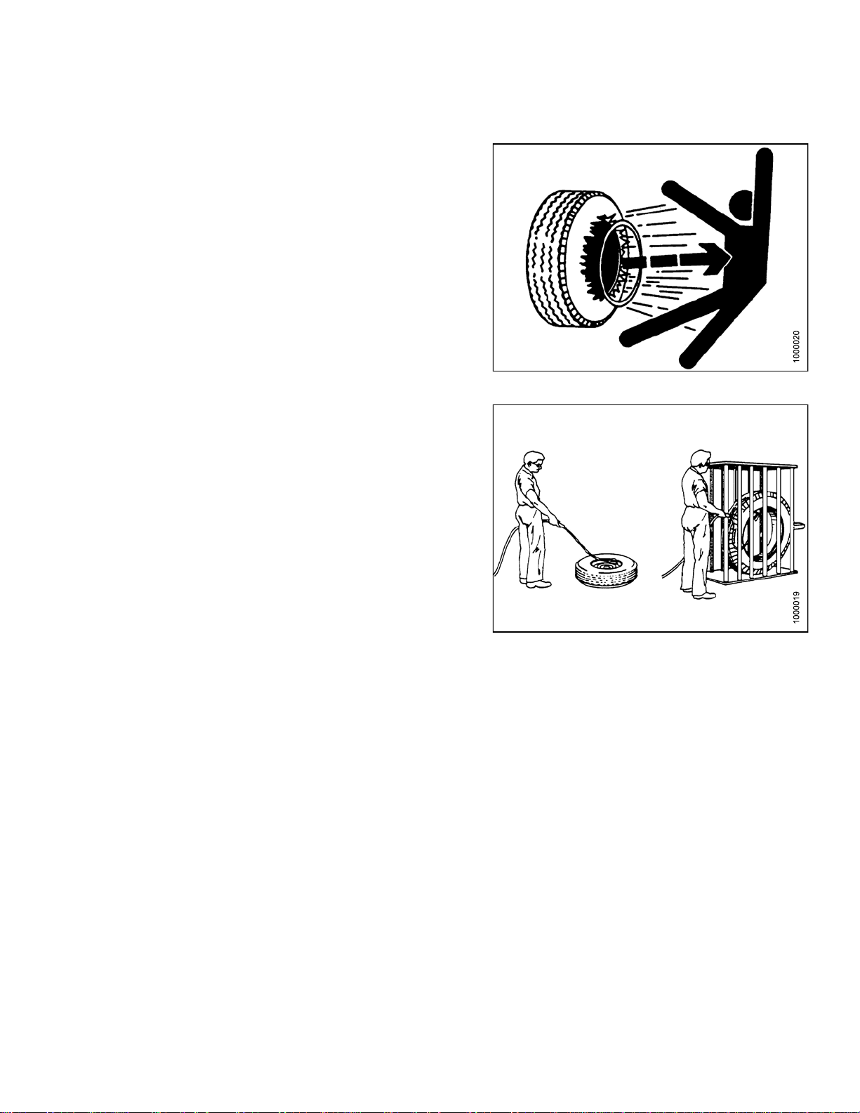
1.6 Tire Safety
• Failure to follow proper procedures when mounting a tire
on a wheel or rim can produce an explosion that may
result in serious injury or dea th .
•DoNOT attempt to m ount a tire unless you have the
proper training and equipment.
Figure 1.14: Over-Inflating a Tire
• Have a qualified tire dealer or repair service perform
required tire maintenance.
Figure 1.15: Saf ely Filling a Tire with Air
169489
7
Revision A
Page 16
SAFETY
1.7 Safety Signs
• Keep safety signs clean and legible at all times.
• Replace safety signs that are missing or
become illegible.
• If original parts on which a safety sign was installed are
replaced, be sure the repair part also bears the current
safety sign.
• Safety signs are available from your Dealer
Parts Department.
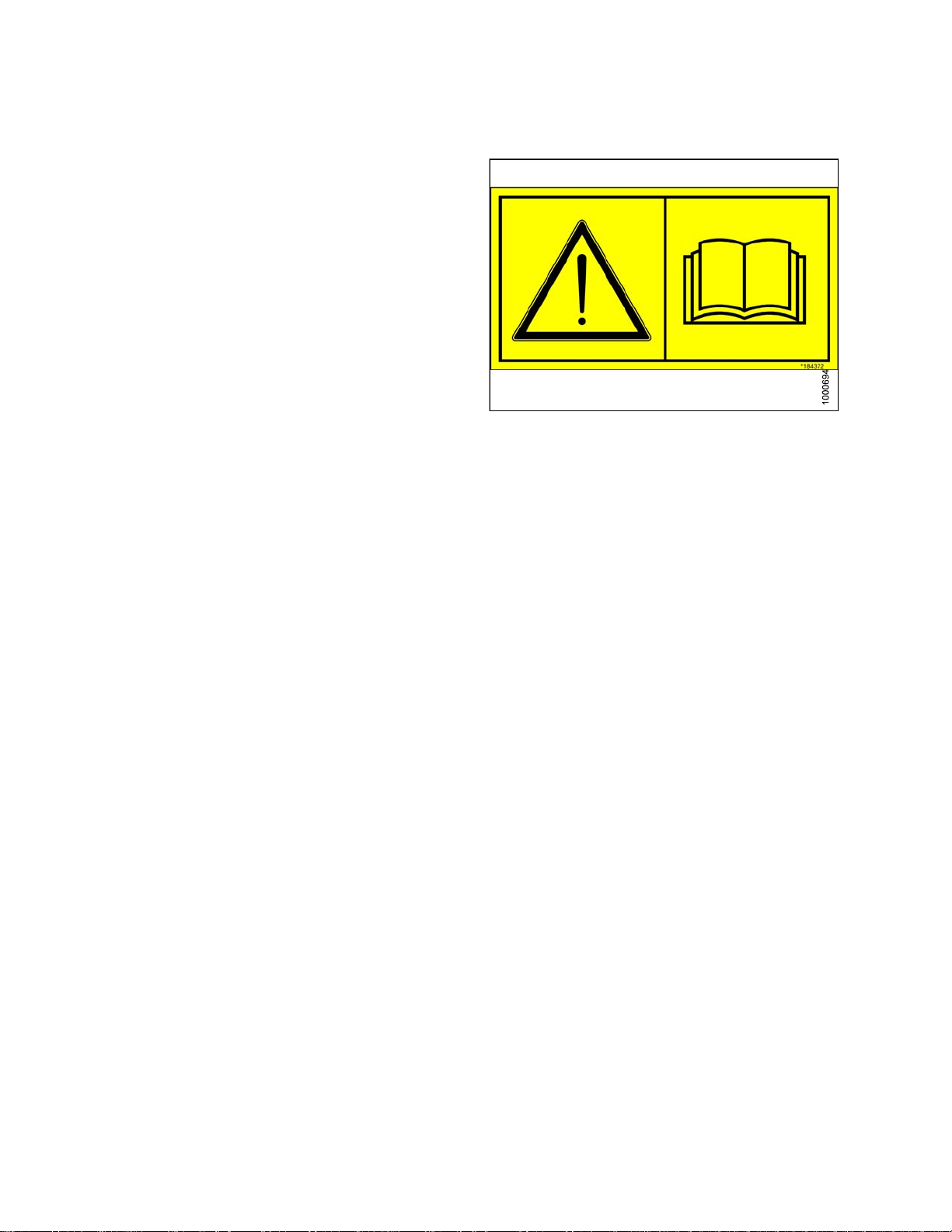
1.7.1 Installing Safety Decals
Figure 1.16: Read Operator’s Manual before
Operating
To i n s t a l
1. Be sure th
2. Decide on
3. Remove t
4. Place th
5. Small ai
l a safe ty dec al, follow these steps:
e sign in position an d slowly peel back the remaining pap er, smoothin g the sign as it is applied.
r pockets can be smoothed out or pricked with a pin.
e installation area is c l ea n and dry.
the exact location before you remove the decal backing paper.
he smaller portion of the split backing paper.
169489 8 Revision A
Page 17

1.8 Safety S ign Locations
SAFETY
Figure 1
A - MD #184370 B - MD #166466 C - MD #184372 D - MD #184371
E - MD #184420 F - MD #237298
.17: Header Decals
169489 9 Revision A
Page 18
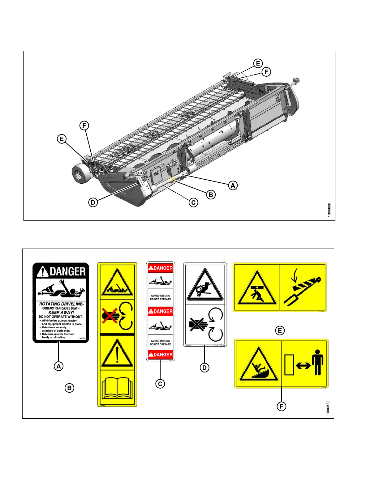
SAFETY
Figure 1.18: Driveline and Hold-Down Decals
A - MD #30316 B - MD #191099 C - MD #36651
D - MD #184422 (Behind Endshield) E - MD #237229 F - MD #237254
169489 1
0
Revision A
Page 19

SAFETY
1.9 Interpreting Safety Signs
In the safety sign explanations below, (a) refers to the top or
left position panel, (b) refers to the bottom or right position
of the safety decal depending on decal orientation.
NOTE: If there are more than two panels in a decal, the
lettering will continue downward or to the right,
depending on decal orientation.
1. MD #30316
a. Rotating driveline
b. DA NGER
Rotating Driveline contact can cause death - KEEP
AWAY! Do not operate without:
• All driveline guards, tractor and equipment
shields in place.
• Drivelines securely attached at both ends.
• Driveline guards that turn freely on driveline.
2. MD #36651
a. Rotating driveline
b. DA NGER
• Stop engine and remove key before opening
shield.
• Do not operate if guard is missing or shields not
in place.
• Failure to comply will result in death or serious
injury.
Figure 1.19: MD #30316
Figure 1.20: MD #36651
169489
1
1
Revision A
Page 20

3. MD #166466
a. High pressure oil hazard.
b. WARNING
Do no t go near leaks.
• High pressure oil easily punctures skin causing
serious injury, gangrene, or death.
• If injured, seek emergency medical help.
Immediate surgery is required to remove oil.
•Donotusefinger or skin to check for leaks.
• Lower load or relieve hydraulic pressure before
loosening fittings.
4. MD #184370
a. Crushing hazard.
b. CAUTION
• Rest header on ground or engage cylinder safety
props before going under unit.
SAFETY
Figure 1.21: MD #166466
• Failure to comply could result in death or serious
injury.
5. MD #184371
a. Open drive hazard.
b. WARNING
• Guard missing. Do not operate.
• Keep all shields in place.
Figure 1.22: MD #184370
Figure 1.23: MD #184371
169489
2
1
Revision A
Page 21
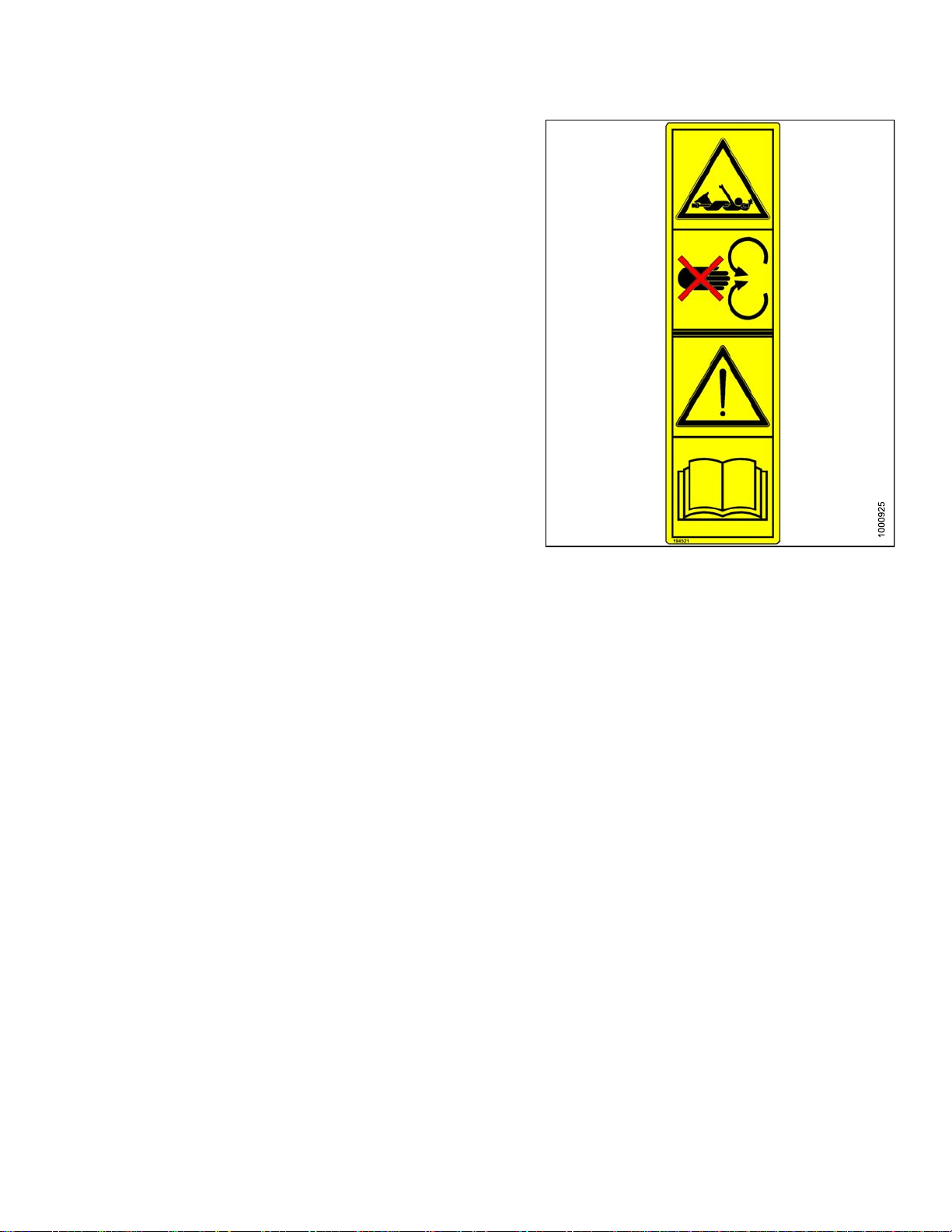
6. MD #184372
a. General hazard pertaining to machine operation
and servicing.
b. CA UTION
To avoid injury or death from improper or unsafe
machine operation:
• Read the operator’s manual and follow all safety
instructions. If y ou do not have a manual, obtain
one from your Dealer.
• Do not allow untrained persons to operate
the machine.
SAFETY
• Review safety instructions with all
Operators annually.
• Ensure that all safety sign s are installed
and legible.
• Make certain everyone is clear of machine
before starting engine and during operation.
• Keep riders off the machine.
• Keep all shields in place and stay clear of
moving parts.
• Disengage header drive, put transmission in
Neutral, and wait for all movement to stop before
leaving operator’s position.
• Shut off the engine and remove the key from
ignition before servicing, adjusting, lubricating,
cleaning, or unplugging machine.
• Engage safety props to prevent lowering of
raised unit before servicing in the raised position.
• Use slow moving vehicle emblem and flashing
warning lights when operating on roadways
unless prohibited by law.
Figure 1.24: MD #184372
7. MD #184420
a. Crushing hazard
WARNING
• To avoid injury from being pinned or crushed,
stay clear of header while machine is operating
or in motion. Failure to comply could result in
death or serious injury.
169489 1
3
Figure 1.
25: MD #184420
Revision A
Page 22

8. MD #184422
a. Keep shields in place hazard.
b. WARNING
• To avoid injury, stop engine before opening
power drive system shield.
• Keep all shields in place.
SAFETY
Figure 1.26: MD #184422
169489
4
1
Revision A
Page 23
9. MD #191099
a. Auger entanglement hazard.
b. CA UTION
• To avoid injury from entanglement with rotating
auger, stand clear of header while machine
is running.
c. General hazard pertaining to machine operation
and servicing.
d. CA UTION
• Read the operator’s m anual and follow safety
instructions. If y ou do not have a manual, obtain
one from your Dealer.
• Do not allow untrained persons to operate
the machine.
• Review safety instructions with all
Operators annually.
• Ensure that all safety sign s are installed
and legible.
SAFETY
• Make certain everyone is clear of machine
before starting engine and during operation.
• Keep riders off the machine.
• Keep all shields in place and stay clear of
moving parts.
• Disengage header drive, put transmission in
Neutral, and wait for all movement to stop before
leaving operator’s position.
• Stop the engine and remove the key from ignition
before servicing, adjusting, lubricating, cleaning,
or unplugging machine.
• Engage safety props to prevent lowering of unit
before serv icing in the raised position.
• Use slow moving vehicle emblem and flashing
warning lights when operating on roadways
unless prohibited by law.
Figure 1.
27: MD #191099
169489 1
5
Revision A
Page 24

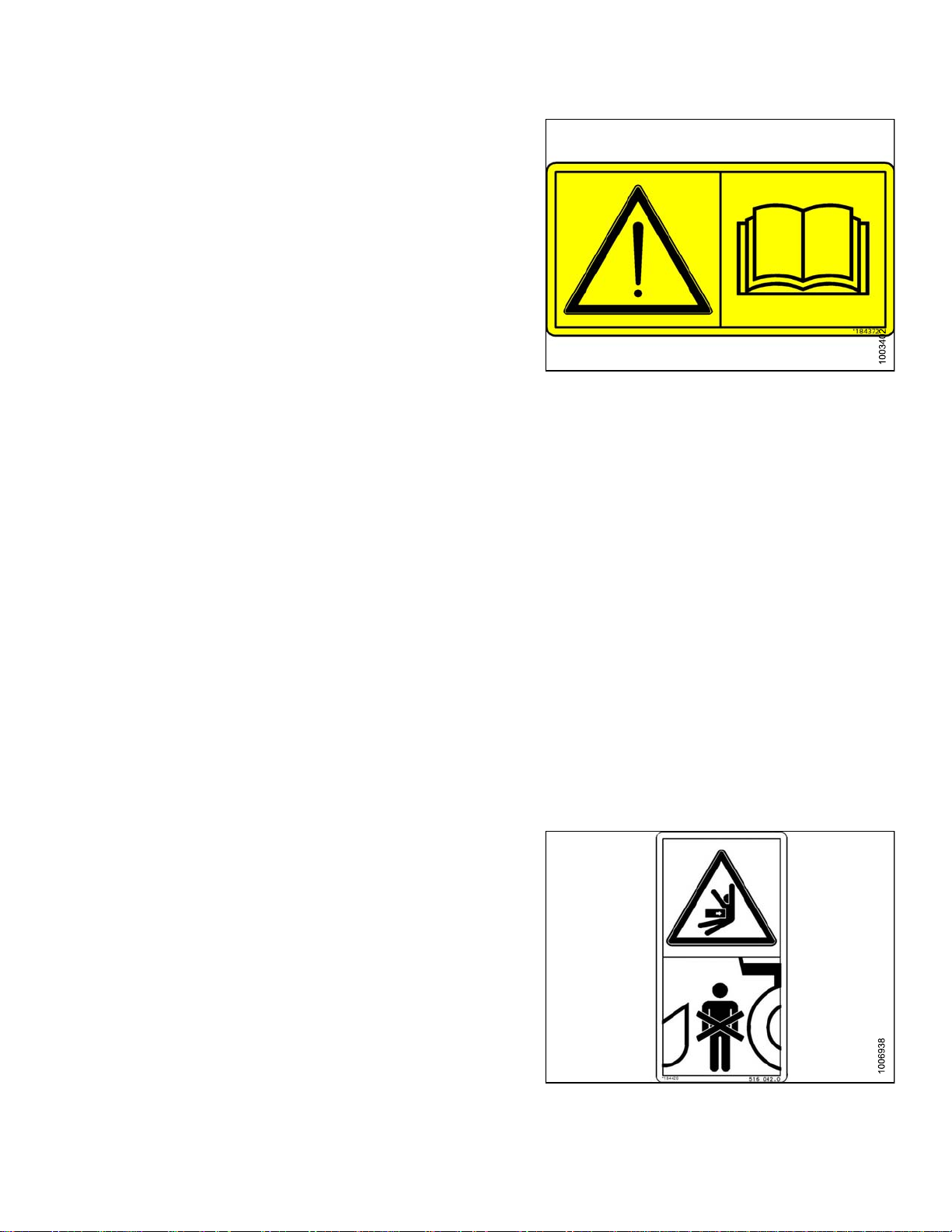
10. MD #237229
a. Header crushing hazard
b. WARNING
• Rest header on ground or engage cylinder safety
props before going under unit.
11. MD #237254
a. Header entanglement hazard
b. CAUTION
• To avoid injury from entanglement with crop
gathering elements, stand clear of header while
machine is running.
SAFETY
Figure 1.28: MD #237229
12. MD #237298
a. Auger entanglement hazard
b. CAUTION
• To avoid injury from rotating auger, stand clear
of auger while machine is running.
Figure 1.29: MD #237254
Figure 1.30: MD #237298
169489 1
6
Revision A
Page 25

2 Description
2.1 Definitions
The following definitions and acronyms may be used in this manual:
Term Definition
API American Petroleum Institute.
ASTM American Society of Testing and Materials.
Bolt
CGVW Combined Vehicle Gross Weight.
Finger t
F.F. F. T
GVW Gross Vehicle Weight.
hp Horsepower
JIC
n/a Not a
Nut
NPT
ORB
ORFS
Pick-Up Header
ight
A headed and externally threaded fastener that is designed to be paired with a nut.
Finger tight is a reference position where sealing surfaces or components are
making contact with each other and the fitting has been tightened to a point where
the fitting is no longer loose.
Flats from finger tight.
Joint Industrial Council: a standards body that developed the standard sizing and
shape for original 37° flared fitting.
pplicable
An internally threaded fastener that is designed to be paired with a bolt.
National Pipe Thread: a style of fitting used for low pressure port openings. Threads
on NPT fittings are uniquely tapered for an interference fit.
O-ring Boss: a style of fitting commonly used in port opening on manifolds, pumps
and m otors.
O-ring Face Seal: a style of fitting commonly used for connecting hoses and tubes.
This style of fitting is also commonly called ORS, which stands for O-ring Seal.
A machine that picks up grain that has been cut and laid in windrows, and is
attached to a combine.
PTO Power Take-Off.
RoHS (Reduction of
Hazardous Substances)
SAE Society Of Automotive Engineers.
Screw
Soft joint
spm
Ten si o n
T.F. F. T.
169489
A directive by the European Union to restrict the use of certain hazardous
substances (such as hexavalent chromium used in some yellow zinc platings).
A headed and externally threaded fastener that threads into preformed threads or
forms its own thread in one of the mating parts.
A joint made with the use of a fastener where the joining materials are compressible
or experience relaxation over a period of time.
Strokes per minute
Axial load placed on a bolt or screw, usually measured in pounds (lb) or Newtons (N).
Turns from finger tight.
7
1
Revision A
Page 26

Term Definition
DESCRIPTION
Tor qu e
Torque angle
Torque-ten
Tractor Agricultural-type tractor.
Truck A four-wheel highway/road vehicle weighing no less than 7500 lb (3400 kg).
Washer
sion
The product of a force X lever arm length, usually measured in foot-pounds (ft·lbf)
or Newton-meters (N·m).
A tightening procedure where the fitting is assembled to a p recondition (finger
tight) and then the nut is turned further a number of degrees or a number of flats to
achieve its final position.
The relationship between the assembly torque applied to a piece of hardware and
the axial load it induces in the bolt or screw.
A thin cylinder with a hole or slot located in the center and is to be used as a spacer,
load distribution element or a locking mechanism.
169489 1
8
Revision A
Page 27

DESCRIPTION
2.2 PW8 Header Specifications
PW8 Header Model SWATHMASTER™
Frame and Structure
WidthToEdgeofTires
PICK-UP
AUGER
Width (Transport Lights Extended)
Depth
Height (Transport Lights Extended)
Weight (Not Including Completion Packages) 3006 lb (1366 kg)
Carrier
Lighting Two Amber Transport
Manual Storage Header Mounted Manual Storage Case
rBatWidth
Finge
Actual Picking Width
Draper Width
Quantity of Pick-Up Fingers
per Drives
Dra
Diameter (including Flighting) 24 in. (615 mm)
ube Diameter
T
Quantity of Fingers
Refer to Section 2.3 PW8 Header
Dimensions, page 20
AGCO, CLAAS, Case IH, New Holland,
John Deere, Lexion
N/A
Refer to Section 2.3 PW8 Header
Dimensions, page 20
392
Two5.9cu. in. (97cc)HydraulicMotors
16 in. (410 mm)
13–22
Finger Diameter
Speed (Combine Dependent)
DRIVELINE
Type
Connections Locking Collar
TIRES
Size 18.5 / 8.5 x 8
Pressure
NOTE: Specifications and design are subject to change without notice or obligation to revise previously
sold units.
5/8 in. (16 mm) Diameter. Induction Hardened
141–204 rpm
Heavy Duty PTO Type, Fully Shielded
With Built-In Clutch.
35–45 psi (240–310 kPa)
169489 1
9
Revision A
Page 28

DESCRIPTION
2.3 PW8 Header Dimensions
Figure 2.1: Header Dimensions
A - 222-3/4 in. (5658 mm) B - 203-1/2 in. (5170 mm) C - 178-1/8 in. (4523 mm)
D - 187-5/8 in. (4766 mm) E - 209-3/8 in. (5318 mm)
Figure 2.2: Header Dimensions
A - 96-7/8 in. (2460 mm) B - 98-7/8 in. (2513 mm) C - 60-3/4 in. (1544 mm) D - 54-3/8 in. (1380 mm)
169489 2
0
Revision A
Page 29

DESCRIPTION
2.4 PW8 Component Identification
Figure 2
A - Transport Light B - Endshield - Fixed
D - Stripper Plate
G - Auger Pan H - Multi-Coupler Receptacle
J - Driveline
M-Hold
P - Gauge Wheel Q - Reflector
S - Draper Finger
V - Forward Draper Deck W - Rear Draper Deck X - Auger Flighting
.3: PW8 Header
-Down Cylinder Safety Prop
E - Auger F - Auger Finger
K-ManualCase
N - Draper Drive Motor
T - Hold-Down U - Hold-Down Fiberglass Rod
C - Window Frame
I-NotUsed
L - Endshield - Latched
-Down Lift Cylinder
O-Hold
R-Handle
169489
1
2
Revision A
Page 30

Page 31

3 Operation
3.1 Owner/Operator Responsibilities
CAUTION
• It is your responsibility to read and understand this manual completely before operating the header.
Contact your MacDon Dealer if an instruction is not clear to you.
• Follow all safety messages in the manual and on safety decals on the machine.
• Remember that YOU arethe key to safety. Good safety practices protectyou and the people aroundyou.
• Before allowing anyone to operate the header, for however short a time or distance, make sure they
have been instructed in its safe and proper use.
• Review the manual and all safety related items with all Operators annually.
• Be alert for other Operators not using recommended procedures or not following safety precautions.
Correct these mistakes immediately, before an accident occurs.
• Do NOT modify the machine. Unauthorized modifications may impair the function and/or safety and
affect machine life.
• The safety information given in this manual does not replace safety codes, insurance needs, or laws
governing your area. Be sure your machine meets the standards set by these regulations.
169489 2
3
Revision A
Page 32

OPERATION
3.2 Operational Safety
Follow these safety precautions:
CAUTION
• Follow all safety and operational instructions given in your combine Operator's Manual. If you do not
have a combine manual, get one from your Dealer and read it thoroughly.
• Never start or move the machine until you are sure all bystanders have cleared the area.
• Stop combine engine and remove key before adjusting or removing plugged material from the machine.
A child or even a pet could engage the drive.
• Check for excessive vibration and unusual noises. If there is any indication of trouble, shut down and
inspect the machine.
CAUTION
Follow proper shutdown procedure:
• Engage combine brake.
• Turn off engine and remove key.
• Wait for all movement to stop.
• Dismount and engage safety props before inspecting raised machine.
• Operate only in daylight or good artificial light.
169489
4
2
Revision A
Page 33

OPERATION
3.3 Endshields
The endshields are molded polyethylene covers that are attached to the ends of the header. They mainly provide
shielding for the header drive components and also display the make of the combine. The left endshield is hinged
to the endsheet, and can be opened for routine maintenance or easily removed for major servicing. The right
endshield is bolted directly to the header.
3.3.1 O pening LH Endshield
DANGER
Stop engine and remove key from ignition before leaving operator’s seat for any reason. A child or even
a pet could engage an idling machine.
1. Lower header to ground, shut down engine, and
remove key from ignition.
2. Unlock endshield (B) by turning latch (A)
counterclockwise until it stops (slightly more than
one-half turn) using a standard end screwdriver.
3. Grasp forward end of endshield (A) and pull open
until support (B) engages and holds endshield in open
position.
NOTE: If additional access to the drive area is
required, remove the endshield. Refer to
Section: 4.5.1 Removing LH Endshield,
page 93.
Figure 3.1: Endshield Closed
Figure 3.2: Endshield O pen
169489 2
5
Revision A
Page 34

OPERATION
3.3.2 Closing
1. Move the endshield (A) slightly so that support (B) can
be moved out of lock position.
2. Close shield (A), ensuring that magnet (B) and stop (C)
in header frame are aligned. This will ensure that the
latch (D) will line up with the receptacle (E).
NOTE: Latch (D) and magnet (B) positions are properly
adjusted at the fac tory.
LH Endshield
Figure 3.3: Disengaging Support
3. If required, loosen nuts (B) on clips (C) at the back of
the shield (A) and reposition the shield. Tighten the
nuts (B) but do not overtighten to prevent damage to
the shield.
Figure 3.4: Closing Endshield
Figure 3.5: Adjusting Endshield
169489 2
6
Revision A
Page 35

OPERATION
4. Close the shield and turn latch (A) clockwise until
it stops (slightly more than one-half turn ) using a
standard end screwdriver.
5. Check that magnet (B) on endshield is against the stop
on endsheet and that latch is engaged.
Figure 3.6: Endshield Closed
169489
7
2
Revision A
Page 36

OPERATION
3.4 Header Lift Cylinder Safety Props
Refer to your Combine Operator’s Manual.
169489 2
8
Revision A
Page 37

OPERATION
3.5 Hold-Down Lift Cylinder Safety Props
WARNING
To avoid bodily injury from fall of raised hold-down, always engage cylinder safety props before going
under raised hold-down for any reason.
IMPORTANT:
To prevent damage to hold-down support arms, do not transport header with cylinder safety props engaged.
Lift cylinder safety props are located at each hold-down support arm.
To engage lift cylinder safety props:
1. Raise hold-down to maximum height.
2. Move safety props to engaged position.
3. Lower hold-down onto safety props.
To disengage lift cylinder safety props:
4. Raise hold-down to maximum height.
5. Move safety props to disengaged position.
Figure 3.7: Engaged
Figure 3.8: Disengaged
169489 2
9
Revision A
Page 38

OPERATION
3.6 Daily Start-up Check
CAUTION
• Besure combineand header areproperlyattached,
all controls are in Neutral and combine brake is
engaged.
• Clear the area of other persons, pets, etc. Keep
children away from machinery. Walk around the
machine to be sure no one is under, on, or close to
it.
• Wear close-fitting clothing and protective shoes
with slip-resistant soles.
• Remove foreign objects from the machine and
surrounding area.
• As well, carry with you any protective clothing and
personal safety devices that COULD be necessary
through the day. Don’t take chances. You may
need a hard hat, protective glasses or goggles,
heavy gloves, a respirator or filter mask, or wet
weather gear.
• Protect against noise. Wear a suitable hearing
protective device such as ear muffs or ear plugs
to protect against objectionable or uncomfortable
loud noises.
Complete the following tasks each day before start-up:
1. Check the machine for leaks or any parts that are
missing, broken, or not working correctly.
NOTE: Use proper procedure when searching for
pressurized fluid leaks. Refer to 4.9.3 Hydraulic
Hoses and Lines, page 160.
2. Clean all lights and reflective surfaces on the machine.
3. Perform all daily maintenance. Refer to Section
Maintenance Schedule/Record, page 88.
Figure 3.9
personal s
: Use protective clothing and
afety devices
169489 3
0
Revision A
Page 39

OPERATION
3.7 Shutdown Procedure
CAUTION
Before leaving the combine seat for any reason:
• Park on level ground if possible.
• Lower the header fully.
• Place all controls in Neutral, and engage combine brake.
• Stop engine and remove key from ignition.
• Wait for all movement to stop.
169489 3
1
Revision A
Page 40

OPERATION
3.8 Break-In Period
CAUTION
Before investigating an unusual sound orattempting tocorrect a problem, shut offengine, engage parking
brake and remove key.
1. After attaching header to combine for the first time, operate the machine slowly for 5 minutes, watching and
listening care fully FROM THE COMBINE SEAT for bin d ing or interfering parts.
2. Perform the items specified in Maintenance Schedule/Record, page 88, under AFTER FIRST 10 HOURS.
NOTE: Until you become familiar with the sound and feel of your new header, be extra alert and attentive.
169489 3
2
Revision A
Page 41

OPERATION
3.9 Changing Header Opening
To minimize the set up at the dealer, PW8 combine pick-up headers are shipped from the factory in a configuration
to suit a particlular combine make, model and feeder house size. Each header includes the necessary parts and
hardware to modify it, if required, to accommodate another model of combine with a different size feeder house.
The conversion procedure is included in the Unloading and Assembly Instruction that is provided with the header.
Factory Header Configuration Modified Header Configuration
Combine Make Combine Model(s) Feeder House Size Combine Model(s) Feeder House Size
John Deere
New Holland
9550, 9650, 9750,
9660, 9760, 9860
CR970, CR
980
55 in. (1397 mm)
50 in. (12
70 mm)
9610
CX 60 in. (1524 mm)
CR920, CR940,
CR960
65 in. (1651 mm)
40 in. (1016 mm)
169489 3
3
Revision A
Page 42

OPERATION
3.10 Header Attachment and Detachment
This section includes instructions on attaching and detaching PW8 Pick-Up Headers to the combines listed below.
PW8 headers are configured for each particular combine model.
Combine Refer to Section
Case IH 3.10.1 Case IH, page 34
John Deere 60, 70 and S Series 3.10.2 John Deere 60, 70, and S Series, page 41
New Holland C R, CX 3.10.3 New Holland CR/CX Series Combine, page 47
3.10.1 Case IH
This section provides instruction for attaching the MacDon
PW8 pick-up to and detaching from Case IH combines,
including 5088, 6088, 7088, 7010, 8010, 7120, 8120, 9120,
5130, 6130, 7130, 7230, 8230, 9230, 5140, 6140, 7140.
AttachingtoCaseIHCombine
1. Pull handle (A) on combine to raise hooks (B) on both
sides of the feeder house.
Figure 3.10: Case IH Combine
Figure 3.11: Feederhouse Locks
169489 3
4
Revision A
Page 43

OPERATION
2. Slowly drive combine up to header until feeder house
saddle (A) is directly under the header top cross
member.
3. Raise feeder house slightly to lift header, ensuring
feeder saddle is properly engaged in header frame.
WARNING
Stop combine engine and remove key before making
adjustments to machine. A child or even a pet could
engage the drive.
4. Stop engine, and remove key from ignition.
5. Lift lever (A) on header at left side of feeder house,
and push handle (B) on combine to engage locks (C)
on both sides of the feeder house.
6. Push down on lever (A) so that slot in lever engages
handle (B) to lock handle in place.
Figure 3.12: Header on Combine
7. If locks (C) do not fully engage pins (D) on header,
loosen nut (E), and adjust position of pin (D) as
necessary (both sides). Tighten nut.
8. To obtain full lock on pin (D) when (A) and (B) are
engaged, loosen bolts (F), and adjust lock as required.
Retighten bolts.
e 3.13: Engaging Locks
Figur
169489 3
5
Revision A
Page 44

OPERATION
9. Rotate disc (B) on header driveline storage hook (A),
and remove driveline from hook.
10. Pull back collar ( A) on end of driveline, and push onto
combine output shaft (B) until collar locks.
Figure 3.14: Driveline
11. Open cover (A) on header receptacle.
12. Push in lock button (B), and pull handle (C) upward to
full open position.
13. Remove coupler (D) from combine, and clean mating
surfaces.
Figure 3.15: Attaching Driveline
Figure 3.16: Coupler Lock
169489 3
6
Revision A
Page 45

OPERATION
14. Position coupler (A) onto header receptacle, and push
handle (B) downward to engage coupler pins into
receptacle.
15. Push handle to closed position until lock button (C)
snaps out.
16. Open cover on header electrical receptacle (D).
17. Remove electrical connector (E) from storage cup on
combine, and route to header receptacle (D).
18. Align lugs on electrical connector (E) with slots in
receptacle, push connector onto receptacle (D), and
turn collar on connector to lock it in place.
Figure 3.17: Attaching Coupler
Detaching from Case IH Comb ine
DANGER
Stop engine and remove key from ignition before leaving operator’s seat for any reason. A child or even
a pet could engage an idling machine.
1. Choose a level area. Position header slightly above
ground. Stop engine and remove key.
2. Push in lock button (C), and pull handle (B) upward to
release coupler (A).
Figure 3.18
169489 3
7
Revision A
Page 46

OPERATION
3. Position coupler (A) onto storage plate (B) on combine.
4. Disconnect electrical connector (A) from header.
Figure 3.19
5. Place electrical connector (A) into storage cup (B) on
combine.
Figure 3.20
Figure 3.21
169489 3
8
Revision A
Page 47

OPERATION
6. Ensure cover on header electrical receptacle (A)
closes.
7. Push handle (B) on header down into storage position
until lock button (C) snaps out.
8. Close cover (D).
9. Open driveshield (A) on combine.
10. Pull back collar (B) on driveline (C), and pull driveline
(C) from combine.
Figure 3.22
169489 3
e3.23
Figur
9
Revision A
Page 48

OPERATION
11. Slide driveline into storage hook (A) on header so that
disc (B) drops to secure driveline.
12. Close driveshield (A) on combine.
Figure 3.24
13. Lift lever (A), pull and lower handle (B) to disengage
feeder house/header lock (C).
14. Lower feeder house until it disengages header support.
15. Slowly back combine away from header.
Figure 3.25
Figure 3.26
169489 4
0
Revision A
Page 49

OPERATION
3.10.2 John De
This section p
PW8 Pick-Up He
combines incl
and S Series -
rovides instruction for attaching the MacDon
ader to and detaching from John Deere
uding: 9660, 9760, 9860, 9670, 9770, 9870
Contour Master and Level Land.
ere 60, 70, and S Series
Figure 3.27: John Deere Combine
AttachingtoJohnDeere60,70andSSeriesCombine
1. Push handle (A) on combine coupler toward feeder
house to retract pins (B) at bottom corners of feeder
house.
2. Slowly drive combine up to header until feeder house
saddles (A) are directly under the header top beam (B).
3. Raise feeder house to lift header, ensuring feeder
saddles are properly engaged in header frame.
4. Position header until slightly off the ground, stop engine
and remove key from ignition.
WARN
Stop combine engine and remove key before making
adjustments to machine. A child or even a pet could
engage the drive.
169489
ING
4
e 3.28: Feederhouse Locks
Figur
ure 3.29: Header on Combine
Fig
1
Revision A
Page 50

OPERATION
5. Open driveshield on combine feeder house.
6. Rotate disc (B) on header driveline storage hook (A),
and remove driveline from hook.
Figure 3.30: Combine Driveshield
7. Pull back collar (A) on e n d of d r ive line and slide
driveline on feeder house driveshaft until the
collar locks.
8. Close feeder house driveshield.
Figure 3.31: Driveline
Figure 3.32: Attaching Driveline
169489
2
4
Revision A
Page 51

OPERATION
9. Remove cover (A) from combine multi-coupler
receptacle.
10. Pull handle (A) on header to release multi-coupler
(B) from storage position. Remove coupler, and push
handle back into header to store.
Figure 3.33: Combine Receptacle
11. Place coupler (A) onto combine receptacle.
12. Pull out knob (B) to release handle, and pull handle (C)
to engage pins in coupler.
Figure 3.34: Releasing Coupler
Figure 3.35: Engaging Coupler
169489 4
3
Revision A
Page 52

OPERATION
13. Pull handle (A) to full horizontal position as shown to
fully engage coupler, and to extend pins (B) at base of
feeder house into the locking plates (C). Knob (D) will
engage handle to lock handle.
NOTE: If handle does not move to full horizontal position,
check alignment of locking plates (A) on the
header with locking pins (B) on both sides of the
feeder house. If necessary, loosen nuts (C), and
adjust plates (A) to line up with pins (B). Retighten
nuts.
Figure 3.
Figure 3.37: Aligning Locking Plates
36: Locking Feederhouse
169489
4
4
Revision A
Page 53

OPERATION
Detaching from John Deere 60, 70, and S Series Combine
1. Choose a level area. Position header slightly above
ground. Stop engine and remove key.
WARNING
Stop combine engine and remove key before making
adjustments to machine. A child or even a pet could
engage the drive.
2. Pull out knob (A) on combine coupler, and move
handle (B) toward feeder house to release coupler (C)
from combine, and to retract locking pins at base of
feeder house.
3. Lower handle (A) on header, and position coupler (B)
in header as shown.
Figure 3.38
Figure 3.39
169489 4
5
Revision A
Page 54

OPERATION
4. Raise handle (A) to lock coupler.
5. Open feeder house driveshield (B).
6. Pull back colla r (A) on driveline, and pull driveline off
combine output shaft.
Figure 3.40
7. Slide driveline in storage hook (A) on header so that
disc (B) drops to secure driveshaft.
Figure 3.41
Figure 3.42
169489 4
6
Revision A
Page 55

OPERATION
8. Close combine driveshield (A).
9. Start engine, and lower feeder house until saddle (B)
disengages and clears header support (C).
10. Slowly back combine away from header.
Figure 3.43
3.10.3 New Holland CR/CX Series Combine
This section provides instructions for attaching the MacDon
PW8 Pick-Up Header to and detaching from all New
Holland CR/CX Series combines.
Attach
ing to New Holland CR/CX Series Combine
WARNING
Stop combine engine and remove key before making
adjustments to machine. A child or even a pet could
engage the drive.
1. Pull handle (A) on combine to raise hooks (B) on both
sides of the feeder house.
169489
4
Figure
Figure 3.45: Feeder House Locks
3.44: New Holland Combine
7
Revision A
Page 56

OPERATION
2. Slowly drive combine up to header until feeder house
saddle (A) is directly under the header top beam (B).
3. Raise feeder house to lift header, ensuring feeder
saddle (A) is properly engaged in header frame.
4. Lift lever (A) on header at left side of feeder house and
push handle (B) on combine so that hooks (C) engage
pins (D) on both sides of the feeder house.
5. Push down on lever (A) so that slot in lever engages
handle to lock handle in place.
Figure 3.46: Header on Combine
6. If locks (C) do not fully engage pins (D) on header,
loosen nut (E) and adjust position of pin (D) as
necessary (both sides). Tighten nut.
7. To obtain full lock on pin (D) when (B) and (A) are
engaged, loosen bolts (F), and adjust lock as required.
Retighten bolts.
e 3.47: Engaging Locks
Figur
169489 4
8
Revision A
Page 57

OPERATION
8. Rotate disc (B) on header driveline storage hook (A),
and remove driveline from hook.
9. Pull back collar (B) on end of driveline, and push onto
combine output shaft (A) until collar locks.
Figure 3.48: Driveline
10. Open cover (A).
11. Push in lock button (B), and pull handle (C) halfway up
to open position.
Figure 3.49: Attaching Driveline
Figure 3.50: Header Receptacle
169489 4
9
Revision A
Page 58

OPERATION
12. Remove coupler (A) from storage location on combine,
and clean mating surface of coupler.
13. Position coupler onto header receptacle (A), and push
handle (B) downward to engage pins into receptacle.
14. Push handle (B) to closed position until lock button (C)
snaps out.
15. Open cover (D) on header electrical receptacle.
Figure 3.51: Combine Coupler/Connector
16. Remove electrical connector (E) from combine.
17. Align lugs on electrical connector (E) with slots
in header receptacle, and push connector onto
receptacle. Turn collar on connector to lock it in place.
Figure 3.52: Attaching Coupler
169489 5
0
Revision A
Page 59

OPERATION
Detaching from New Holland CR/CX Combine
1. Choose a level area. Position header slightly off the
ground. Stop engine and remove key.
WARNING
Stop combine engine and remove key before making
adjustments to machine. A child or even a pet could
engage the drive.
2. Push in lock button (C), and pull handle (B) upward to
release coupler (A).
3. Remove coupler (A) from header receptacle.
4. Position coupler (A) onto storage plate (B) on combine.
5. Disconnect electrical connector from header, and place
in storage cup (C) on combine.
Figure 3.53
Figure 3.54
169489 5
1
Revision A
Page 60

OPERATION
6. Close cover (A) on header hydraulic receptacle, and
cover (B) on electrical receptacle.
7. Push handle (C) on header down into storage position,
and the lock button (D) snaps out.
8. Pull back collar (A) on driveline (B), and pull driveline
from combine.
Figure 3.55
9. Slide driveline into storage hook (A) on header so that
disc (B) drops to secure driveline.
Figure 3.56
Figure 3.57
169489 5
2
Revision A
Page 61

OPERATION
10. Lift lever (A), pull and lower handle (B) to disengage
feeder house/header lock (C).
11. Lower feeder house until it disengages header support.
12. Slowly back combine away from header.
Figure 3.58
169489 5
3
Revision A
Page 62

OPERATION
3.11 Header Transport
Refer to your combine operator’s manual for transporting headers when attached to the combine.
3.11.1 Transport Lights
The transport lights, which are mounted on both ends of
the header, are activated by switches in the combine cab.
They function as flashing hazard lights and turn signals,
and should be positioned perpendicular to the endsheet.
See your combine operator’s manual for operating
instructions.
Figure 3.5
9: Transport Lights
169489 5
4
Revision A
Page 63

OPERATION
3.12 Header Operation
Satisfactory operation of the header in all situations requires making proper adjustments to suit various crops and
conditions.
Correct operation reduces crop loss and increases productivity. As well, proper adjustments and timely maintenance
will increase the length of service you rece ive from the machine.
The variables listed below and detailed on the following pages, will affect the performance of the header.
You will quickly become adept at adjusting the machine to give you the desired results. Most of the adjustments
have been set at the factory but if desired, the settings can be changed to suit crop conditions.
Variable Section
Pick-Up Speed 3.12.1 Operating Speed, page 55
Auger Speed Auger Speed, page 56
Header Height Header Height, page 62
Pick-Up Height Pick-Up Height, page 63
Hold-Down Position Hold-Down Position, page 65
Hold-Down Rod Angle Hold-Down Rod Angle, page 66
Auger Position Auger Position, page 56
Stripper Plates Stripper Plate Clearance, page 61
Draper Belt Tension
Checking Draper Belt Tension, page 68
3.12.1 Operating Speed
Performance of the pick-up in va rious crop an d field conditions largely depends upon the speed at w hich the drapers
are turning, and the forward speed of the combine.
• If the swath is pushed ahead, the draper speed is too low, and some of the crop may remain unpicked.
• If the swath is torn apart and is pulled toward the combine header, the draper speed is too high, and uneven
combine feeding will occur.
Generally, optimum pick-up speed for most conditions shall be selected so that the swath is always pushed slightly
ahead.
Draper speed is adjusted from the combine cab by regulating oil flow to the pick-up hydraulic motors, typically usin g
the reel speed controls for the combine. The ratio of pick-up speed to combine ground speed can be set using the
combine header controls. See your combine operator’s manual.
IMPORTANT:
Do NOT over-speed pick-up. Over-speeding the pick-up causes premature wear of drive
components and adversely affects pick-up performance.
The following operating speeds are suggested:
Front and Rear Deck Aft Roller: 51 rpm per 1 mph (1.6 km/h) of combine ground speed.
Example: For combining at 5 mph (8 km/h), the rear roller shaft should run at 51 x 5 mph = 255 rpm
(51 x 8/1.6 = 255 rpm).
169489 5
5
Revision A
Page 64

OPERATION
Adjusting Draper Speed
Draper speed is determined by measuring the rpm of the
aft roller on the rear pick-up deck.
1. Check the roller rpm (A) with a handheld tachometer,
and adjust with the reel speed control in the combine.
NOTE: Some combines are equipped with a speed
sensor (B) that indicates the roller rpm in the
combine cab.
3.12.2 Auger
Figure 3.60
Auger Speed
The header is sup
connection to th
or slower auger
Refer to Sectio
plied with an auger drive sprocket to match your combine. The auger is driven by a direct
e feeder house, and auger speed depends on the feeder house speed. In certain crops, a higher
speed may be desired. Contact your Dealer for available sprocket options.
n: Auger Drive Sprockets, page 117 for instructions on changing the sprocket.
Auger Position
The auger position is c ritical for a smooth, high capacity flow of crop into the feeder house. It is factory set for normal
crop conditions but may require adjustment for different crops and conditions.
The auger must rotate freely without touching the auger pan or stripper bars, and the position should be checked
prior to operating the pick-up.
The clearance (A) between the auger flighting (B) and
pan (C) should be 3/16–7/16 in. (5–11 mm).
169489 5
Figure 3.61: Auger to Pan Clearance
6
Revision A
Page 65

OPERATION
The clearance (A) between the auger fingers (B) and pan
(C) should be 13/16–1 in. (20–25 mm).
Figure 3.62: Finger to Pan Clearance
Adjusting Auger Position
If adjustments are required, proceed as follows:
NOTE: Both ends of the auger are adjustable to maintain a uniform clearance across the width of the
header.
NOTE: Access the auger/pan area from top of header.
DANGER
Stop engine and remove key from ignition before leaving operator’s seat for any reason. A child or even
a pet could engage an idling machine.
1. Lower header to the ground, shut down combine and
remove key from ignition.
2. Open endshield (A) on left end of header. Refer to
Section: 3.3.1 Opening LH Endshield, page 25.
Figure 3.63
169489 5
7
Revision A
Page 66

OPERATION
3. Loosen the two bolts (A) on auger stops on both ends
of header.
4. Loosen jam nuts (B) on adjuster bolts (C).
5. Turn adjuster bolt (C) to lower or raise the auger.
6. Manually rotate the auger to check for interference, and
to check clearances between the auger flighting and
auger pan, and adjust as necessary.
7. Tighten jam nuts (B), and downstop nuts (A).
8. Check clearances between auger flighting and stripper
plates, and adjust as required. Refer to Section:
Stripper Plate Clearance, page 61.
Figure 3.64: Left End
Figure 3.65: Right End
Auger Float
The auger has an upward float range of 1-5/16 in. (34 mm), but can be locked so that it does not float, which may
be desirable in certain crop conditions.
169489 5
8
Revision A
Page 67

OPERATION
Locking Auger Float
Lock auger as follows:
DANGER
Stop engine and remove key from ignition before
leaving operator’s seat for any reason. A child or
even a pet could engage an idling machine.
1. Lower header to the ground, shut down combine and
remove key from ignition.
2. Open left endshield (A). Refer to Section: 3.3.1
Opening LH Endshield, page 25.
3. Loosen the two bolts (A) on auger upstops (B) on both
ends of header.
4. Slide the stops (B) downward until they contact the
rubber blocks (C) on the auger arm.
Figure 3.66
5. Tighten bolt s (A).
Figure 3.67: Left End
169489 5
Figure 3.68: Right End
9
Revision A
Page 68

OPERATION
6. Close endshield (A). Refer to Section: 3.3.2 Closing
LH Endshield, page 26.
Unlocking Auger Float
Unlock auger float as follows:
DANGER
Figure 3.69
Stop engine and remove key from ignition before
leaving operator’s seat for any reason. A child or
even a pet could engage an idling machine.
1. Lower header to the ground, shut down combine and
remove key from ignition.
2. Open left endshield (A). Refer to Section: 3.3.1
Opening LH Endshie ld, page 25.
3. Loosen the two bolts (A) on auger upstops (B) on both
ends of header.
4. Slide stops (C) upward to desired float range.
5. Tighten bolts (A).
6. Close left endshield. Refer to section: 3.3.2 Closing
LH Endshield, page 26.
Figure
3.70
169489 6
re 3.71: Left End
Figu
0
Revision A
Page 69

OPERATION
Stripper Plate Clearance
The header is equipped with a pair of stripper plates (A)
located on either side of the center opening, and are
designed to minimize crop carryover behind the auger
when properly adjusted.
Figure 3.72: Right End
• If the clearance between the flighting and stripper plate
is too large, crop will tend to wrap around the auger and
disrupt crop flow into the combine.
• If the clearance is too little, the auger flighting may
contact the stripper plates, and cause excessive wear
to the flighting and stripper plates.
Stripper plate clearance has been set to 1/8–1/4 in. (3–6
mm) at the factory.
Figure 3.73: Stripper Plates
Checking Stripper Plate Clearance
Check and adjust the clearance if necessary whenever the auger position is changed:
To check stripper plate clearance:
DANGE
Stop engine and remove key from ignition before leaving operator’s seat for any reason. A child or even
a pet could engage an idling machine.
1. Lower header to the ground, shut down combine and remove key from ignition.
2. Manually rotate the auger to check for interference, and to check clearances between the auger flighting and
stripper plates.
R
NOTE: Access the auger/stripper plate area from top of header.
169489 6
1
Revision A
Page 70

Adjusting Stripper Plate Clearance
1. If necessary, adjust clearance as follows:
a. Loosen nuts (A) on the stripper plate (B) to adjust
and move plate to achie v e clearance (C) of
1/8–1/4 in. (3–6 mm).
b. Tighten nuts (A).
c. Recheck the clearance .
OPERATION
3.12.3 Ope
Header He
Header he
the groun
(305 mm).
Heade
heade
side
oper
cab d
ight is the distance between the deck pivot and
d. Recommended operating height (A) is 12 in.
r height adjustments are m ade with the combine
r height control. The numbered decals (A) on both
s of the header provide an indication of the header
ating height if the combine is not equipped with an in
isplay of header height.
rating Height
ight
Figure 3.7
Figur
4: Stripper Plate Clearance
e 3.75: Operating Height
ocation of end plate (B) on the decal represents the
The l
er height. The position between 4 and 5 indicates the
head
ommended operating height of 12 in. (305 mm).
rec
ition 1 indicates the lowest height, and 7 is the highest.
Pos
169489 6
gure 3.76: Height Gauge
Fi
2
Revision A
Page 71

OPERATION
If your combine is factory equipped with Auto Header
Height Control (AHHC), refer to the following for operating
and adjustment information.
1. The optimum pick-up height is 12 in. (305 mm) off the
ground under normal conditions, and the AHHC should
be set to the Neutral position.
2. Use the AHHC to change the pick-up operating height
to suit your specific crop condition. Refer to your
combine operator manual for details.
3. If the AHHC sensor requires adjustment, refer to the
PW8 Pick-Up Header Technical Manual MD #169841,
or your MacDon Dealer.
Pick-Up Height
Pick-upheight(A)isthedistancebetweenthepick-up
finger and the ground.
The recommended pick-up height is 1 in. (25 mm), and
may need to be changed to suit field conditions.
Two general symptoms will indicate that an adjustment is
required:
• If the pick-up leaves material in the swath, the pick-up
height is too high.
• If the pick-up fingers are wearing quickly or are picking
up dirt and stones, the pick-up height is too low.
Adjusting Pick-Up Height
Adjust the pick-up height as follows:
1. Check that tire pressure is 35–45 psi (240–310 kPa).
2. Adjust the operating height (A) so that the rear roller
is 12 in. (300 mm) off the ground.
Figure 3.77: Pick-Up Height
169489 6
Figure 3.78: Operating Height
3
Revision A
Page 72

OPERATION
3. Check the pick-up height (A). If adjustment is required,
or if another distance is desired, proceed to next step.
4. Raise the header with the combine control to take the
load off the wheels.
5. Loosen the two nuts (A) on wheel plate.
6. Position wheel pla te cog to desired number on frame.
Number 2 position should provide 1.0 in. (25 mm)
clearance to ground.
7. Tighten nuts (A).
Figure 3.79: Pick-Up Height
8. Repeat steps 5.–7. for the opposite side.
9. Adjust the AHC if necessary.
Figure 3.80: Pick-Up Height Adjustment
169489 6
4
Revision A
Page 73

OPERATION
3.12.4 Hold-Down
Hold-Down Position
Hold-down position refers to the position of the fiberglass
rods (A) with respect to the swath, and can be adjusted
accordingtocropconditions.
The fiberglass rods (A) hold the swath in contact with the
pick-up belts, and guide the c rop under the a uger. Ideally,
constant down pressure on the crop will assist in pick-up
performance.
Adjust the hold-down position with the combine reel height
control to suit crop conditions:
• (1) Short Crop
• (2) Average Crop
• (3) Heavy Crop
IMPORTAN
Before re
unplug th
T:
versing the combine feeder house to
e feeder, fully raise the hold-down.
169489 6
Figure 3.81: Hold-Down Positions
5
Revision A
Page 74

OPERATION
Hold-Down Rod Angle
The angle between the fiberglass rods and the hold-down support arms is adjustable, and should be set to optimize
crop flow into the combine. The factory setting should be satisfactory for most crop conditions, but if desired, the
rodscanbeadjusted.
1. Loosen the two hex head M12 nuts (A) on both ends
of the hold-down cross member (B) to allow the cross
member to rotate.
2. Rotate the crossbar to the desired position with the
handle (D).
3. Tighten nuts (A).
Figure 3.8
3.12.5 Cr
Crop deflectors can be installed where there is a tendency for stems to collect under the hold-down support arm
pivot. They are bolted to the frame inside the left endsheet for shipment from the factory and should have been
removed at the dealer during set up, and installed or retained by the operator. Under no circumstances should the
header be run until the crop deflectors are removed from inside the header drive compartment.
op Deflectors
2: Hold-Down Rod Angle
CAUTION
To avoid damage to the header drive, do not operate the header with the crop deflectors in the as shipped
location inside the header drive co mpartment.
InstallingCropDeflectors
DANGER
Stop engine and remove key from ignition before leaving operator’s seat for any reason. A child or even
a pet could engage an idling machine.
1. Retrieve crop deflectors from combine cab or
previously stored location.
2. Lower hold-down.
3. Lower header to the ground, shut down combine and
remove key from ignition.
169489 6
6
Revision A
Page 75

OPERATION
4. Position crop deflector (A) onto header endsheet as
shown and install with two M12x25 bolts (B) and nuts
provided in bag. Bolt heads must face inboard.
5. Repeat above step for opposite deflector.
Figure 3.83: Installing Deflector
Removing Crop Deflectors
DANGER
Stop engine and remove key from ignition before leaving operator’s seat for any reason. A child or even
a pet could engage an idling machine.
1. Lower the hold-down.
2. Lower header to the ground, shut down combine and
remove key from ignition.
3. Remove crop deflectors (A) by removing bolts (B).
4. Store deflectors and hardware in combine cab or an
alternate safe location.
Figure 3.84
169489 6
7
Revision A
Page 76

3.12.6 Draper Belt Tension
OPERATION
The pick-up dr
NOTE: There should b
NOTE:
NOTE:
NOTE: Drapers may nee
aper belts are set at the factory, but the draper tension should be checked before operating.
e visible sag in the underside of the draper.
Draper tension only needs to be set to prevent slippage.
Drapers may be s
reduce the stic
ticky when new. Talcum or baby powder applied to the drapers should help to
kiness.
dtobelooserthannormalforthefirst few hours during break-in.
Checking Draper Belt Tension
DANGER
Stop engine and remove key from ignition before leaving operator’s seat for any reason. A child or even
a pet could engage an idling machine.
1. Raise the header fully, and engage the combine lift
cylinder stops.
2. Stop engine and remove key from ignition.
3. There should be 1.0 in. (25 mm) of sag (C). When the
draper is properly tensioned, it should be visible in the
slot (B) in the deck frame, and lined up with the notch
as shown.
NOTE: Ensure draper tension is the same for left and right
side for optimum draper tracking.
4. If the tension requires adjusting, refer to Section
Adjusting Draper Belt Tension on Front Deck, page
69 or Section Adjusting Draper Belt Tension on Rear
Deck, page 69
Figure 3.85: Draper Tension
A - Draper Belt
B - Slot in Deck Frame C - Sag
169489 6
8
Revision A
Page 77

OPERATION
Adjusting Draper Belt Tension on Front Deck
If the tensio n needs adjusting , proceed as follows:
IMPORTANT:
Draper tensio
Over-tighte
• Joining bolts to pull out of draper.
• Damage to the rollers or bearings.
• Twisting and wrinkling of drapers.
1. Front Deck – Both Sides
a. Loosen three clamp bolts (A) on each side.
b. Loosen jam nut (B).
c. Turn adjuster nut (C) to set draper tension. Proper
tension is achieved when the draper lines up with
the indicator notch (D).
d. Tighten clamp bolts (A) and jam nut (B).
n only needs to be set to prevent slippage. D o NOT tighten draper above the indicator notch.
ning may cause:
Adjust
If the tensio n needs adjusting , proceed as follows:
IMPORTANT:
ing Draper Belt Tension on Rear Deck
Draper tension only needs to be set to prevent slippage. Do NOT tighten draper above the indicator notch.
Over-tightening may cause:
•Joini
•Damag
•Twis
ng bolts to pull out of draper.
e to the rollers or bearings.
ting and Wrinkling of drapers.
Figure 3
Opposit
.86: Front Deck – Left Side, Right Side
e
169489 6
9
Revision A
Page 78

1. Rear Deck – Right Side
a. Loosen three clamp bolts (A).
b. Loosen jam nut (B).
c. Turn adjuster nut (C) to set draper tension. Proper
tension is achieved when the draper lines up with
the indicator notch (D).
d. Tighten clamp bolts (A) and jam nut (B).
2. Rear Deck – Left Side
a. Loosen two clamp bolts (A).
b. Loosen jam nut (B).
c. Turn adjuster nut (C) to set draper tension. Proper
tension is achieved when the draper lines up with
the indicator notch (D).
OPERATION
Figure 3.87: Rear Deck – Right Side
d. Tighten clamp bolts (A) and nut (B).
Figure 3.88: Rear Deck – Left Side
169489 7
0
Revision A
Page 79

OPERATION
3.12.7 Driveline
Clutch
The header to combine driveline contains a radial pin
clutch (A) to provide protection against overload. When an
obstruction encounters the auger and creates an overload,
the clutch will slip and emit a rattling sound and pulsating
motion when slippage occurs.
Frequent slippage for more than two or three seconds may
result in c lutch damage.
IMPORTANT:
Prolonged o
slipping w
clutch.
If the clutch becomes permanently damaged, refer to
Replacing Driveline Clutch, page 100.
peration of the header with the clutch
ill cause damage to the header and/or
Figure 3
.89: Radial Pin Clutch
Guard
DANGER
To avoid serious injury or death, do not operate machine if guard is missing or not in place.
The driveline guard (A) normally remains attached to
the driveline. Tethers (light chains) (B) on either end of
the driveline guard prevent rotation of the guard. The
guard can be removed from the driveline for maintenance
purposes. See Section Removing Driveline Guard, page
101
Figure 3.90
169489
1
7
Revision A
Page 80

OPERATION
3.13 Unplugging the Header
CAUTION
Stop combine engine and remove key before removing plugged material from header. A child or even a
pet could engage the drive.
1. Stop forward movement of the combine and disengage the header.
2. Fully raise the hold-down.
3. Disengage the pick-up draper drive.
4. Run the feeder b ackwards with the reve rse controls in the combine cab to clear the plug.
IMPORTANT:
To prevent damage to the feeder motor, do NOT engage the feeder reverser for more than five seconds if
the feeder and auger will not turn.
IMPORTANT:
Pick-up drapers cannot run in reverse. ANY attempt to run the pick-up in reverse will seriously damage the
drapers and/or draper drive motors.
169489
2
7
Revision A
Page 81

OPERATION
3.14 Storing the Header
Do the following at the end of each operating season:
CAUTION
Never use gasoline, naphtha or any volatile material for cleaning purposes. These materials may be toxic
and/or flammable.
1. Clean the header thoroughly.
2. Store in a dry, protected place if possible. If stored outside, always cover combine with a waterproof canvas or
other protective material.
3. Raise header and engage header lift cylinder safety props on combine.
4. If possible, block up the header to take weight off tires.
5. Repaint all worn or chipped painted surfaces to prevent rust.
6. Loosen draper belts.
7. Lubricate the header thoroughly, leaving excess grease on fittings to keep moisture out of bearings. Apply
grease to exposed threads, cylinder rods, and sliding surfaces of components.
8. Check for worn components, and repair as necessary.
9. Check for broken components, and order replacements from your MacDon Dealer. A ttention to these items right
away will save time and effort at beginning of next season.
10. Replace or tighten any missing or loose hardware. Refer to Section: 4.2.1 Torque Specifications, page 76.
169489 7
3
Revision A
Page 82

Page 83

4 Maintenance and Servicing
The following instructions are provided to assist the Operator in the maintenance and servicing of the PW8 Pick-Up
header. Detailed maintenance, service, and parts information are contained in the PW8 Pick-Up Header Technical
Manual MD #169841 that is available from your MacDon Dealer, and in the PW8 Parts Catalog MD #169497.
Log hours of operation, and use the Maintenance S chedule/Record provided to keep a record of scheduled
maintenance. Refer to Maintenance Schedule/Record, page 88.
4.1 Prepare Header for Servicing
CAUTION
To avoid personal injury, before servicing header or opening drive covers, perform the following:
• Fully lower the header. If necessary to service in the raised position, always engage header lift cylinder
safety props on combine.
• Stop engine and remove key.
• Engage park brake.
• Wait for all moving parts to stop.
169489 7
5
Revision A
Page 84

MAINTENANCE AND SERVICING
4.2 Maintenance Specifications
4.2.1 Torque Specifications
The following tables give correct torque values for various bolts, cap screws, and hydraulic fittings.
• Tighten all bolts to the torques specified in chart (unless otherwise noted throughout this manual).
• Replace hardware with the same strength and grade bolt.
• Check tightness of bolts periodically, using the tables below as a guide.
• Torque categories for bolts and cap screws are identified by their head markings.
Metric Bolt Specifications
Table 4.1 M
Spinning N
Nominal
etricClass8.8BoltsandClass9Free
ut
Torque (ft·lbf)
(*in·lbf)
Torque (N·m)
Size
Min. Max. Min. Max.
3-0.5
3.5-0.6
4-0.7
5-0.8
6-1.0
8-1.25 20 23 28 30
10-1.5 40 45
12-1.75 70 78 95 105
14-2.0 113 124 152 168
16-2.0 175 193 236 261
20-2.5 341 377 460 509
24-3.0 589 651 796 879
*13 *14
*20 *22
*29 *32
*59 *66
*101 *112
1.4 1.6
2.2 2.5
3.3 3.7
6.7 7.4
11.4 12.6
55
60
Figure 4.1
A-NominalSize
169489 7
6
Revision A
Page 85

MAINTENANCE AND SERVICING
Table4.2MetricClass8.8BoltsandClass9Distorted Thread Nut
Nominal
Torque (ft·lbf)
(*in·lbf)
Torque (N·m)
Size
Min. Max. Min. Max.
3-0.5
3.5-0.6
4-0.7
5-0.8
6-1.0
8-1.25
10-1.5 28 30 37 41
12-1.7548536572
14-2.0
16-2.0 119 132 161 178
20-2.5 233 257 314 347
24-3.0 402 444 543 600
Table 4.3 Metric Class 10.9 Bolts and Class 10 Free Spinning Nut
Nominal
*9 *10
*14 *15
*20 *22
*40 *45
*69 *76
*167 *185
77
Torque (ft·
85 104 115
lbf)
(*in·lbf)
11.1
1.5 1.7
2.3 2.5
4.5
7.7
18.8 20.8
Torque (N·m
5
8.6
)
Size
Min. Max. Min. Max.
3-0.5
3.5-0.6
4-0.7
5-0.8
6-1.0
8-1.25 28 31 38 42
5
10-1.
12-1.75 97 108 132 145
14-2.0 156 172 210 232
.0
16-2
20-2.5 472 521 637 704
24-3.0 815 901 1101 1217
*18 *19
*27 *30
*41 *45
*82 *91
*140 *154
56 62
242 267 326 360
1.8 2
2.8 3.1
4.2 4.6
8.4 9.3
14.3 15.8
75
83
169489
7
7
Revision A
Page 86

MAINTENANCE AND SERVICING
Table 4.4 Metric Class 10.9 Bolts and Class 10 Distorted Thread Nut
Nominal
Size
Torque
(ft·lbf)(*in·lbf)
Min. Max. Min. Max.
Torque (N·m)
3-0.5
3.5-0.6
4-0.7
5-0.8
6-1.0
8-1.25 19 21 26 29
10-1.5 38 42 51
12-1.7566739099
14-2.0 106 117 143 158
16-2.0 165 182 222 246
20-2.5 322 356 434 480
0
24-3.
*12 *13
*19 *21
*28 *31
*56 *62
*95 *105
556 614 750 829
1.3 1.5
2.1 2.3
3.1 3.4
6.3
10.7 11.8
7
57
169489 7
8
Revision A
Page 87

MAINTENANCE AND SERVICING
Metric Bolt Specifications Bolting into Cast Aluminum
Table 4.5 Metric Bolt Bolting into Cast Aluminum
Bolt Torque
Nominal
Size
8.8
(Cast Alumin
um)
(Cast Alumin
10.9
um)
ft·lbf N·m ft·lbf N·m
M3 1
M4 2.6 4
M5
5.5
8
M6 6 9 9 12
M8 14 20 20 28
M10 28 40 40
55
M12 52 70 73 100
M14
M16
Flare-Type Hydraulic Fittings
1. Check flare (A) and flare seat (B) for defects that might
cause leakage.
2. Align tube (C) with fitting (D) and thread nut (E) onto
fitting w ithout lubrication until contact has been made
between the flared surfaces.
Figure 4.2
A-NominalSize
3. Torque the fitting nut (E) to the specified number of
FFFT or to a given torque value shown in the following
table.
4. To prevent the fitting (D) from rotating, use two
wrenches. Place one wren ch on the fitting body (D)
and tighten the nut (E) with the other wrench to the
torque shown.
5. Assess the final condition of the connection.
Figure 4.3
A-Flare
C - Tube
E-Nut
B-FlareSe
D-Body
at
169489 7
9
Revision A
Page 88

MAINTENANCE AND SERVICING
Table 4.6 Flare-Type Hydraulic Tube Fittings
SAE No.
Tube Size
O.D. (in.)
Thread
Size (in.)
Flats (in.)
Nut Size
Across
Torque Value
ft·lbf
1
Flats From Finger
Tight (FFFT)
N·m Flats Turns
3
4 1/4 7/16 9/16 9 12 1 1/6
5
6
8 1/2 3/4 7/8 34 46 1 1/6
10
12
14 7/8 1-3/8 1 - 3/8 90 122 3/4 1/8
16 1
3/16 3/8 7/16
5/16 1/2 5/8
3/8 9/16 11/16
5/8 7/8
3/4 1-1/16 1-1/4
1-5/16 1-1/2
146621
681
12 16 1
18 24 1
75
105 142
102
3/4 1/8
3/4 1/8
1/6
1/6
1/6
1/6
1. Torque values shown are based on lubricated connections as in reassembly.
169489 8
0
Revision A
Page 89

MAINTENANCE AND SERVICING
O-Ring Boss (ORB) Hydraulic Fittings (Adjustable)
1. Inspect O-ring (A) and seat (B) for dirt or obvious
defects.
2. Back off the lock nut (C) as far as possible. Ensure that
washer (D) is not loose and is pushed toward the lock
nut (C) as far as possible.
3. Check that O-ring (A) is not on the threads, adjust
if necessary.
4. Apply hydraulic system o il to the O-ring (A).
5. Install fitting (
B) into port until back up washer (D) and
O-ring (A) conta
6. Position angle
one turn.
7. Turn lock nut (C
torque shown.
(B) and the oth
8. Check the final
cts on part face (E).
fittings by unscrewing no more than
) down to washer (D) and tighten to
Use two wrenches, one on the fi tting
er on the lock nut (C).
condition of the fitting.
Figure 4.4
A-O-Ring B-Seat C-Nut
D-Washer
Figure 4.5
A-O-Ring
D - Washer E - Part Face
B-Fitting
C-Nut
169489 8
1
Revision A
Page 90

MAINTENANCE AND SERVICING
Table 4.7 O-Ring Boss (ORB) Hydraulic Fittings (Adjustable)
SAE Dash Size Thread Size (in.)
-3 3/8-24 *106–115 12–13
-4 7/16–20 14–15 19–21
-5 1/2–20 15–24 21–33
-6 9/16–18 19–21 26–29
-8 3/4–16 34–37 46–50
-10 7/8–14 55–60 75–82
-12 1-1/16-12 88–97 120–132
-14 1-3/8-12 113–124 153–168
-16 1-5/16-12 130–142 176–193
-20 1-5/8-12 163–179 221–243
-24 1-7/8-12 199–220 270–298
ft·lbf (*in·lbf)
Torque Value
2
N·m
2. Torque values shown are based on lubricated connections as in reassembly.
169489 8
2
Revision A
Page 91

MAINTENANCE AND SERVICING
O-Ring Boss (ORB) Hydraulic Fittings (Non-Adjustable)
1. Inspect O-ring (A) and seat (B) for dirt or obvious
defects.
2. Check that O-ring (A) is not on the threads, adjust
if necessary.
3. Apply hydraulic system oil to the O-ring.
4. Install fitting (C) in to port until fitting is h a nd tight.
5. Torque fitting (C) per value in chart. See table
4.8 O-Ring Boss (ORB) Hydraulic Fittings
(Non-Adjustable), page 83.
6. Check the fi nal condition of the fitting.
Figure 4.6
Table 4.8 O-Ring Boss (ORB) Hydraulic Fittings (Non-Adjustable)
SAE Dash Size Thread Size (in.)
ft·lbf (*in·lbf) N·m
Torque Val
ue
3
-3 3/8-24 *106–115 12–13
-4 7/16–20 14–15 19–21
-5 1/2–20 15–24 21–33
-6 9/16–18 19–21 26–29
-8 3/4–16 34–37 46–50
-10 7/8–14 55–60 75–82
-12 1-1/16-12 88–97 120–132
-14 1-3/8-12 113–124 153–168
-16 1-5/16-12 130–142 176–193
-20 1-5/8-12 163–179 221–243
-24 1-7/8-12 199–220 270–298
3. Torque values shown are based on lubricated connections as in reassembly.
169489 8
3
Revision A
Page 92

MAINTENANCE AND SERVICING
O-Ring Face Seal (ORFS) Hydraulic Fittings
To tighten O-ring face seal (ORFS) hydraulic fittings, follow these steps:
1. Check components to ensure that the sealing surfaces
and fitting threads are free of burrs, nicks, and
scratches or any foreign material.
Figure 4.7
2. Apply hydraulic system oil to the O-ring (B).
3. Align the tube or hose assembly so that the flat face
of the sleeve (A) or (C) comes in full contact with
O-ring (B).
4. Thread tube or hose nut (D) until hand-tight. The nut
should turn freely until it is bottomed out.
5. Torque fitting further to the torque value in the table
shown in the opposite column.
NOTE: If applicable, hold the hex on the fitting body (E)
to prevent rotation of fitting body and hose when
tightening the fitting nut (D).
6. When assemb ling unions or two hoses together, three
wrenches will be required.
7. Check the final condition of the fitting.
Figure
A - Brazed Sleeve B - O-ring
C - Two Piece Sleeve
E - Fitting Body
4.8
D-Nut
169489 8
4
Revision A
Page 93

MAINTENANCE AND SERVICING
Table 4.9 O-Ring Face Seal (ORFS) Hydraulic Fittings
4
SAE Dash
Size
-3 Note
Thread
Size (in.)
5
Torque Value
ft·lbf
(*in·lbf) N·m
––
-4
-5 Note
-6
-8
-10 1–14 59–65 80–88
-12
-14 Note
-16
-20 1-11/16-12 151–16
-24 2–12 232–256 315–347
-32 2-1/2-12 376–4
9/16–18
5
11/16-16
13/16-16
1-3/16-12
5
1-7/16-12
18–21 25–28
––
29–32 40–44
41–45 55–61
85–94 115–127
––
111–122 150–165
14
7
205–22
510–5
6
61
4.2.2 Recommended Fluids and L ubricants
Lubricant
Grease SAE Multi-Purpose
Specificati
on Description Use
High Temperature Extreme
Pressure (EP2) Performance With
1% Max Molybdenum Disulphide
(NLGI Grade 2) Lithium Base
Extreme P
With 1.5–
(NLGI Gra
ressure (EP) Performance
5% Molybdenum Disulphide
de 2) Lithium Base
As Required Unless
Otherwise Specified.
Drive Mot
or Shaft
• Your machine can operate at top efficiency only if clean lubricants are used.
• Use clean containers to handle all lubricants.
• Store in an area protected from dust, moisture, and other contaminants.
4. Torque values and angles shown are based on lubricated connection, as in reassembly.
5. O-ring face seal type end not defined for this tube size
169489 8
5
Revision A
Page 94

MAINTENANCE AND SERVICING
4.2.3 Convers
Quantity
Area
Flow
Force
Length
Power horsepower hp x 0.7457 = kilowatts kW
Pressure
Tor q u e
ion Chart
Inch-Pound Units
Unit Name Abbreviation
acres acres
US gallons per
minute
pounds force lbf
inch in. x 25.4 = millimeters
foot ft.
pounds per
square inch
pound feet or
foot pounds
pound inches or
inch pounds
gpm
psi
ft·lbf
in·lbf
Factor
x 0.4047 = hectares ha
x 3.7854 = liters per minute
x 4.4482 = Newtons N
x0.305=
x 6.8948 = kilopascals kPa
x .00689 = megapascals MPa
÷ 14.50
x 1.3558 =
x0.1129=
38 =
SI Units (Metric)
Unit Name Abbreviation
meters
bar (non-SI) bar
newton meters
newton meters
L/min
mm
m
N·m
N·m
Temperature
Velocity
olume
V
Weight pounds lbs x 0.4536 = kilograms kg
degrees
fahrenheit
feet per m inute ft/min
feet per second ft/s
miles per hour mph x 1.6063 =
US gallons US gal
ounces oz.
cubic inches in.
˚F(˚F-32) x 0.56 =
x 0.3048 =
x 0.3048 =
x 3.7854 = liters L
x 29.5735 = milliliters ml
3
x 16.3871 =
Celsius
meters per
minute
meters per
second
kilometres per
hour
cubic
centimetres
m/min
km/h
cm
˚C
m/s
3
or cc
169489 8
6
Revision A
Page 95

MAINTENANCE AND SERVICING
4.3 Maintenance Requirements
4.3.1 Maintenance Schedule
The following
Regular maint
will increas
For detailed
Section 4.2.
Service Inte
more than on
IMPORTANT:
maintenance schedule lists the periodic maintenance procedures, organized by service intervals.
enance is the best insurance against early wear and untimely breakdowns. Following this schedule
e machine life.
instructions, refer to the specific headings in this chapter. Use the fluids and lubricants specified in
2 Recommended Fluids and Lubricants, page 85.
rvals: The recommended service intervals are in hours of operation. Where a service interval is given in
e time frame, e.g. "100 hours or Annually", service the machine at w hichever interval is reached first.
Recommende
under adver
d intervals are for average conditions. Service the machine more often if operated
se conditions (severe dust, extra heavy loads, etc.).
CAUTION
Carefully follow safety messages given in 1 Safety, page 1.
169489 8
7
Revision A
Page 96

Maintenance Schedule/Re cord
MAINTENANCE AND SERVICING
Action:
FIRST 10 HOURS
Auger drive chain tension
Hydraulic
Draper belt tension
50 HOURS
Auger drive chain tension
Hydraulic hoses for leaks
Draper belt tension
Draper belt condition
Draper plastic guides for wear
100 HOU
RS
Clean and grease driveshaft
splines
Hour meter reading
Service date
Serviced by
hoses for leaks
-Check
- Lubricate
▲ - Change
Driv
Auger drive chain and bearing
END OF SEASON
eline slip-joint and clutch
Tire pressure
Wheel bolt torque
se fasteners
Loo
Bearings an d seals
ck-up fingers for wear
Pi
Height control sensor pivot
points
lean and touch-up worn paint
C
spots
Clean header
Check header for wear
169489 8
8
Revision A
Page 97

MAINTENANCE AND SERVICING
4.3.2 Pre-Sea
Perform the following at the beginning of each operating season:
son/Annual Service
CAUTION
• Review the Operator's Manual to refresh your memory on safety and operating recommendations.
• Review all safety signs and other decals on the header and note hazard areas.
• Be sure all shields and guards are properly installed and secured. Never alter or remove safety
equipment.
• Be sure you understand and have practiced safe use of all controls. Know the capacity and operating
characteristics of the machine.
1. Lubricate machine completely. Refer to Section 4.4 Lubrication, page 90.
2. Perform all annual maintenance. See Maintenance Schedule/Record, page 88.
4.3.3 End of Season Service
Refer to 3.14 Storing the Header, page 73 for end of season servicing information.
169489 8
9
Revision A
Page 98

MAINTENANCE AND SERVICING
4.4 Lubrication
WARNING
To avoidpersonal injury, beforeservicing header or opening drive covers, follow procedures in 4.1 Prepare
Header for Servicing, page 75.
Lubricate the machine after every 100 hours of operation.
The greasing points are marked on the machine by decals
showing a grease gun (A) and grease interval in hours of
operation (B).
Figure 4.9
Log hours of operation and use the Maintenance Record
provided to keep a rec ord of scheduled maintenance.
Refer to Maintenance Schedule/Record, page 88.
4.4.1 Greasing Procedure
WARNING
Stop combine engine and remove key before making adjustments to machine. A child or even a pet could
engage the d rive.
1. Use the recommended lubricants specified in this manual. See 4.2.2 Recommended Fluids and Lubricants,
page 85.
2. Wipe grease fitting with a clean cloth before greasing, to avoid injecting dirt and grit.
3. Inject grease through fitting with grease gun until grease overflows fitting, except where noted.
4. Leave excess grease on fitting to keep out dirt.
5. Replace any loose or broken fittings immediately.
6. If fitting will not take grease, remove and clean thoroughly. Also clean lubricant passageway. Replace fitting if
necessary.
169489 9
0
Revision A
Page 99

MAINTENANCE AND SERVICING
4.4.2 Greasin
Every 100 Hour
s
gPoints
Figure 4.10: Lubricating Header
A - Auger Bearing
C - Auger Chain (see Lubricating Auger Drive Chain, page 113) D - Driveline Clutch
E - Driveline Guard (both ends)
169489 9
B - Driveline Slip-Joint
1
Revision A
Page 100

MAINTENANCE AND SERVICING
4.4.3 Sealed B
1. Clean shaft and coat with rust preventative.
2. Install flangette (A), bearing (B), second flangette (C)
and lock collar (D).
NOTE: The locking cam is only on one side of the bearing.
3. Install (but do not tighten) the flangette bolts (E).
4. When the shaft is correctly located, lock the lock collar
with a punch.
NOTE:
5. Tighten th
6. Loosen the
The collar s
the shaft ro
collar.
turn, and r
line up.
e flangette bolts.
flangette bolts on the mating bearing one
etighten. This will allow the bearing to
earing
houldbelockedinthesamedirection
tates. Tighten the setscrew in the
Figure 4.11
169489 9
2
Revision A
 Loading...