

Page 1

r
PW7
Pick-Up Heade
OPERATOR’S MANUAL
Part #169149 Rev. E
$15
Page 2

Page 3

INTRODUCTION
In order to ensure that the header/pickup will operate smoothly and efficiently for years to come, it is
important that it be correctly set up and properly maintained. Windrow headers with pickup
attachments are designed to pick up windrows of agricultural products such as wheat, soybeans,
canola, barley, etc. and small seed pick ups, and are only intended for such use.
Contained in this manual are safety precautions, operating instructions, and service and maintenance
procedures for the PW7 Pickup Header, and Series IV Rake-Up and SwathMaster pickups. The units
covered in this manual are compatible with John Deere 50 Series and 60 Series combines, Case IH
Combines, New Holland Combines, Gleaner/Massey/Challenger Combines and Claas/Lexion
combines.
The following header sizes are covered in this manual:
13 foot
15 foot
The following pickup models are covered in this manual:
PICKUP SERIES IV ATTACHMENTS
Rake-Up
12’ Small Seed
14’
16’
SwathMaster
12’ Small Seed
14’
16’
Note: Left and right hand are referenced from the operator’s seat looking forward. The illustrations
in this manual may not match your exact machine.
We welcome your suggestions, questions or comments regarding the installation, operation or
maintenance of the header /pickup.
All printed publications are classified as uncontrolled documents and are subject to change without notice at the discretion of MacDon Industries Ltd.
Published: February 2013
Form 169149 Revision E
I
Page 4

TABLE OF CONTENTS
INTRODUCTION............................................................................................................... I
SECTION 1 – PRODUCT IDENTIFICATION
1.1 Serial Numbers ...............................................................................................1
SECTION 2 – SAFETY
2.1 General Safety Practices ................................................................................3
2.2 Safety During Attachment to Combine..........................................................3
2.3 Safety During Operation ................................................................................4
2.4 Safety During Servicing .................................................................................5
2.5 Safety Information/Sign Location..................................................................7
SECTION 3 – SETUP COMPLETION
3.1 Connecting Header/Pickup to Combine – John Deere / Lexion / Agco ........13
3.2 Connecting Header/Pickup to Combine – Case IH / New Holland ...............19
3.3 Feeder house Width Conversion ....................................................................21
3.4 Disengaging Storage Braces / Removing Cylinder Braces ............................22
3.5 Testing Hydraulic Hold down ........................................................................23
SECTION 4 – ADJUSTMENTS
4.1 Tire Pressure and Wheel Nut Torque .............................................................24
4.2 Teeth Height (Wheel) Adjustment .................................................................24
4.3 Suspension Adjustment ..................................................................................25
4.4 Spring wire / Fiberglass Rod Adjustment ......................................................25
4.5 Draper Belt Tensioning ..................................................................................26
4.6 Pickup Drive Belt Tension .............................................................................29
4.7 Speed Control and Height Control Adjustment .............................................29
4.8 Auger Finger Adjustment ..............................................................................30
4.9 Auger Adjustment ..........................................................................................31
4.10 Stripper Bar Adjustment ................................................................................32
4.11 Header Drive Chain Adjustment ....................................................................33
SECTION 5 - OPERATING INSTRUCTIONS
5.1 Operating Speed .............................................................................................35
5.2 Operating Height ............................................................................................36
5.3 Hold down Positioning ..................................................................................37
5.4 Radial Pin Clutch (on driveshaft) ..................................................................38
5.5 Disconnection Header/Pickup From Combine ..............................................38
5.6 Unplugging the Auger....................................................................................39
Form 169149 Revision E
II
Page 5

TABLE OF CONTENTS
SECTION 6 – MAINTENANCE/LUBRICATION
6.1 First Time Use – Maintenance .......................................................................40
6.2 Daily Maintenance/Lubrication (10 hours) ....................................................40
6.3 Weekly Maintenance/Lubrication (50 hours) ................................................40
6.4 Yearly Maintenance/Lubrication (100 hours) ................................................41
6.5 Lubrication Points ..........................................................................................43
6.6 Maintenance/Lubrication Chart/Grease Spec ................................................45
SECTION 7 – SERVICE
7.1 Attaching Pickup to Header ...........................................................................46
7.2 Opening Header Side Panels ..........................................................................48
7.3 Removing Pick Up Shields ............................................................................49
7.4 Hydraulic System ...........................................................................................49
7.5 Drive Shaft Installation ..................................................................................58
7.6 Replacing Header Drive Chain Sprockets .....................................................59
7.7 Replacing Auger Fingers ...............................................................................61
7.8 Replacing Teeth .............................................................................................62
7.9 Replacing Draper Belts ..................................................................................62
7.10 Replacing Drive Belt ......................................................................................63
7.11 Replacing Small Gear Box (RakeUp) ............................................................64
7.12 Crown and/or Pinion Removal/Installation (RakeUp) ...................................68
7.13 Finger Bar Idler Arm Removal/Installation (RakeUp) ..................................71
7.14 Extremity Light Bulb Replacement ...............................................................72
7.15 Wiring Schematics ........................................................................................73
7.16 Belt Guide (SwathMaster Small Seed) ..........................................................73
SECTION 8 – TROUBLE SHOOTING ............................................................................74
SECTION 9 – SPECIFICATIONS
9.1 Torque Chart ..................................................................................................78
9.2 General Specifications ...................................................................................79
SECTION 10 – STORAGE
10.1 Storage of Header/Pickup ..............................................................................80
10.2 Removing From Storage ................................................................................80
INDEX ...................................................................................................................................81
NOTES ..................................................................................................................................82
Form 169149 Revision E
III
Page 6

Form 169149 Revision E
IV
Page 7

SECTION 1
PRODUCT IDENTIFICATION
When ordering parts or when requesting information or assistance always give the following
information:
1. Model
2. Serial Number and Year of Production
Pickup Serial Plate Location
Record model and serial number of your header/pickup below:
PICK-UP
Model _____________________________
Serial Number _____________________________
Form 169149 Revision E
1
Page 8

SECTION 2 - SAFETY
The Safety Alert Symbol is used to alert the reader to important safety messages in this manual.
When you see this symbol, be alert to the possibility of injury. Carefully read and observe all safety
messages and symbols in this manual and on your machine to avoid serious injury or death.
SAFETY ALERT SYMBOL
THIS SYMBOL MEANS
DANGER: Indicates an imminently hazardous situation that,
if not avoided, will result in death or serious injury.
WARNING: Indicates a potentially hazardous situation that,
if not avoided, could result in death or serious injury.
CAUTION: Indicates a potentially hazardous situation that,
if not avoided, may result in minor or moderate injury.
ATTENTION: Indicates a potentially hazardous situation that,
if not avoided, could result in machine damage.
-ATTENTION!
-BECOME ALERT!
-YOUR SAFETY IS INVOLVED!
***IMPORTANT***
Before any person uses this product he/she should take sufficient time learning all necessary
precautions and procedures. Each operator should:
Ensure all people, pets and tools are clear.
Read and fully understand all procedures/precautions in the Operators Manual.
Be instructed and experienced in safe and proper use of the unit.
If information not covered in this manual is required, contact your local dealer.
Form 169149 Revision E
2
Page 9

SECTION 2 SAFETY
2.1 GENERAL SAFETY PRACTICES
All operators must:
Be instructed in the safe and proper use
of this machine and understand all safety
signs and instructions in this manual.
Carefully read all safety messages in this
manual and on your machine.
Keep all safety signs in good condition.
Replace when necessary.
Use and maintain all safety lights and
devices.
Wear necessary protective clothing when
operating or servicing machinery.
Be prepared for emergencies by keeping
a first aid kit and emergency numbers
easily accessible.
Have authorized personnel repair/replace
any damaged or deteriorated parts
immediately to reduce the risk of
personal injury.
Find a spacious, clear, and level surface
to perform any maintenance or
adjustments.
Always shut-off machinery before
performing any adjustments or service.
Never remove obstructions from running
machinery.
Never operate machinery without all
shields in place.
Never engage pickup drive with people
near machine.
Review safety instructions annually.
Modifications to the machine not
approved by MacDon Industries Ltd.
are not allowed. Unapproved
modifications may affect the safety,
reliability, and durability of the
machine and void warranty.
2.2 SAFETY DURING COMBINE
ATTACHMENT
Find a spacious, clear, and flat work area.
Read and understand all installation
procedures. Refer to applicable section
in this manual for reference.
Check for obstructions on combine,
header, and in work area before starting.
Lower header and pickup to ground or
engage feeder safety locks, shut off
combine, remove key and wait until all
moving parts have stopped before
working around header/combine.
Take extreme care when working around
hydraulic lines. Hydraulic fluid under
high pressure can penetrate the skin and
cause serious tissue damage. Seek
immediate medical attention if skin
penetration occurs.
At all times keep body parts away from
the pickup & header when moving.
Form 169149 Revision E
3
Page 10

SECTION 2 SAFETY
2.3 SAFETY DURING OPERATION
A) Extremity Lights
P00541
Extremity Light
P00542
Extremity Lights
The header comes with a left and right hand
extremity light that works in conjunction with
the flashing/signal combine lights. For bulb
replacement, see appropriate section in this
manual.
ATTENTION: Reflectors that are damaged
or worn are to be replaced immediately.
NOTE: Red and Orange Reflectors are visible
from the rear; amber is visible from the front.
New reflectors are available from your dealer.
B) Drive Shaft Safety
Shields are in place for your
protection. Replace any worn or
missing shields.
Drive shaft shields are to rotate
freely at all times (free from binding
while chained). Replace worn shield
bearings promptly.
Never operate header without
shields in place.
Never make modifications to the
drive shaft and shields.
ALWAYS store the drive shaft in
its storage holder. Never use safety
chains to support drive shaft.
DO NOT step on the drive shaft.
Any servicing to the drive shaft
must only be done when the header
is lowered to the ground or the
combine feeder house locks are
engaged, the machine is shut off,
the ignition key is removed and all
moving parts have stopped. Never
make adjustments to, or clean a
running combine.
Make sure drive shaft is attached
properly before operation.
Keep any loose fitting clothing,
jewelry, or long hair away from
moving parts, components, or
retainer chains.
Form 169149 Revision E
4
Page 11

SECTION 2 SAFETY
2.4 SAFETY DURING SERVICING
Any servicing to machinery must only be
done after the header is lowered to the
ground or combine, feeder house is
locked, is shut off, the ignition key is
removed and all moving parts have
stopped.
Take extreme caution around hydraulic
lines. Release all pressure in the system
before servicing or inspecting for leaks.
Hydraulic fluid under high pressure can
penetrate the skin and cause serious
injury. Never use your hands to inspect
lines. Seek immediate medical attention
if fluid is injected into the skin.
Familiarize yourself with proper
servicing procedures in this manual.
Wear protective clothing and use
personal safety devices when required.
A) Tire Safety
A tire that explodes could cause serious
injury. Have a qualified service
technician service the tires.
When inflating tires take extreme care.
An over inflated tire can explode.
Recommended tire pressure is 8-10 psi.
Replace rim if overly rusted or cracks are
noticed.
Stand clear from tire when inflating. Use
a clip-on air chuck, and extension hose.
B) Pickup Hold down Safety Locks
WARNING: OVERHEAD
OBJECT HAZARD Always
activate safety locks before
working under raised hold down.
a) Raise hold down all the way up with
hydraulic cylinder.
b) Engage hold down safety locks as shown.
P00669
Safety Lock Engaged
c) Complete work underneath hold down.
d) Disengage safety locks as shown.
P00670
Safety Lock Disengaged
Form 169149 Revision E
5
Page 12

SECTION 2 SAFETY
C) Combine Feeder House Safety Locks
(Safety Locks Will Vary According to Combine)
WARNING: At no time is any
service procedure to be performed
without the header lowered to the
ground or the feeder house safety locks
engaged.
a) Raise feeder house up completely.
b) Engage feeder house lock.
P00030
Feeder House Lock Engaged
(May not be exactly as shown)
c) Complete work underneath header/pickup.
d) Disengage feeder house lock
P00009
Feeder house Lock Disengaged
(May not be exactly as shown)
Form 169149 Revision E
6
Page 13

SECTION 2 SAFETY
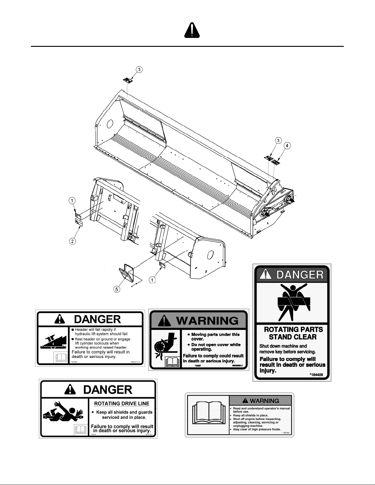
2.5 SAFETY INFORMATION/SIGN LOCATION
Operators must read and follow all safety information in this manual and on safety signs located
on the machine.
Missing, damaged, or illegible safety signs must be replaced immediately.
All new shields or components must include the latest safety signs.
All safety signs and their locations are shown in the illustrations below. Both three-panel (with
text) and two-panel (graphics only) versions are shown.
Safety signs displaying the “Read Operators Manual” symbol are intending to
direct the operator to the Operators Manual for further information regarding
safety, adjustments, maintenance and/or procedure for specific areas of the unit.
RAKE-UP SPECIFIC SAFETY SIGNS
Rotating Drive Hazard, Pinch Point
Located on Belt Guard
184371 2-PANEL 184386
184397 3-PANEL 184393
Form 169149 Revision E
7
Page 14

SECTION 2 SAFETY
Rotating Drive Hazard
Located on Frame under Belt Guard
SWATHMASTER SPECIFIC SIGNS
Rotating Drive Hazard
Located Frame under Belt Guard
Rotating Drive Hazard
Located on Belt Guard
2-PANEL - 184371
2-PANEL - 184401
3-PANEL - 184404
3-PANEL - 184397
Form 169149 Revision E
8
Page 15

SECTION 2 SAFETY
PICKUP SAFETY SIGNS (Rake-Up & SwathMaster)
P00012
Warning, Safety Lock
Located on Lower Hold down Arms
Storage Brace Rotation
RH & LH Wind guard
Pinch Point Located on LH Idler Rotor
Shield (Rake-Up shown, SwathMaster similar)
2-PANEL - 184386
2-PANEL - 191496
3-PANEL - 184365
2-PANEL - 184384
3-PANEL - 184392
3-PANEL - 184393
Form 169149 Revision E
9
Page 16

SECTION 2 SAFETY
HEADER SAFETY SIGNS
P00205
Danger, Rotating Driveline, European
Located on Drive Shaft
P00017
Danger, Missing Shield
Located on Driveshaft (under shield)
Decal, Chain Entanglement
Located Above Chain (behind header LH shield)
3-PANEL - 30316
2-PANEL - 191104
3-PANEL - 36651
2-PANEL - 184401
3-PANEL - 184404
Form 169149 Revision E
10
Page 17

SECTION 2 SAFETY
HEADER FRAME 2-PANEL DECALS
1. Header Crushing Hazard
184370
4. Rotating Drive Hazard
184371
3. Auger Wrapping Hazard
191494
5. Read Operators Manual
2. Keep Shields in Place
184385
Form 169149 Revision E
11
184372
Page 18
SECTION 2 SAFETY
HEADER FRAME 3-PANEL DECALS
1. Header Crushing Hazard - 184398
4. Rotating Drive Hazard
184397
3. Rotating Parts Hazard - 184406
2. Rotating Drive Line Hazard - 184395
Form 169149 Revision E
5. Read Operator’s Manual - 184390
12
Page 19

SECTION 3
SETUP COMPLETION
3.1 CONNECTING HEADER/PICKUP TO
COMBINE: JOHN DEERE / LEXION/
AGCO
NOTE: For Case IH and New Holland
Combines, see Section 3.2
NOTE: The operator of the combine should
be well trained in the use of combine controls.
Improper use of the combine could result in
damage to property or serious injury or
death.
a) Check to see that all header and feeder house
locking devices are open and ready for
engagement.
b) On combines equipped with feeder house
lateral tilt, position the feeder house front
face to be square with feeder house floor.
c) Lower the combine feeder house so that the
feeder house saddle will just pass under the
upper beam of the header.
d) Enter the header opening and lift the header
off the ground. The feeder house saddle and
header beam should now be firmly engaged.
e) Raise the feeder house completely.
f) TURN OFF COMBINE ENGINE,
REMOVE THE KEY FROM THE
IGNITION, AND ENGAGE THE
FEEDER HOUSE SAFETY LOCK.
HEADER UPPER BEAM
FEEDER SADDLE
P00029
Positioning on Combine
(May not be exactly as shown)
P00030
Engaged Feeder House Lock
(May not be exactly as shown)
g) Engage the header locking mechanisms,
wiring and hydraulics. Refer to the
“Completing Hook Up to Your Combine”
section for combine specific instructions.
h) Attach auger drive shaft. See “Drive Shaft
Installation”-section 7.5 in this manual.
i) Disengage the feeder house locks and secure
in the storage position.
Form 169149 Revision E
13
Page 20
SECTION 3 – SETUP COMPLETION
P00009
Disengaged Feeder House Lock
(May not be exactly as shown)
Completing Hook Up To Your Combine
Each combine manufacturer has a different
design for lower locking mechanism on the
header. The locking mechanism is an important
step in protecting your header/pickup from
damage.
On all models the feeder house must be properly
installed onto the header before the locks could
be activated.
ATTENTION: Do not operate or move
header without engaging the lower locking
mechanism. Failure to do so may cause
damage to your equipment.
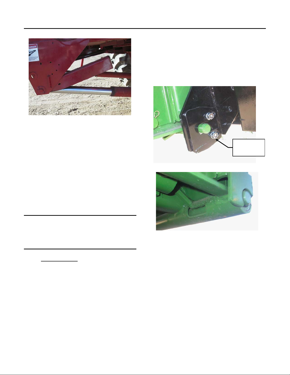
3.1.1 JOHN DEERE
50 Series:
a) Take the John Deere locking pin out of its
storage position and slide it into the slot of
the header.
b) Loosen the nuts of the header locking plates.
c) Position the plate so that the lower corner of
the plate rests against the pin.
d) Check that pin moves freely in and out.
e) Tighten the header adjustment plate nuts.
f) Modification to hydraulic lines and wiring
harnesses may be required if adapter kit is
not available from local dealer.
P00032
HEADER
ADJUSTMENT
PLATE
John Deere Locked Position
P00033
50 Series Open Position
60 Series:
60 Series combines come equipped with a multi
function system, which connects the hydraulics,
electrical and mechanical locks.
a) Remove the hydraulic multi coupler from the
storage bracket.
b) Install the multi coupler onto the feeder
house coupler.
Form 169149 Revision E
14
Page 21

SECTION 3 – SETUP COMPLETION
c) Lower the lever into the engaged or locking
position. This will automatically engage the
header / feeder house locks, wiring and
hydraulics.
P00493R
Hydraulic Coupler in Storage Bracket
P00547
Hydraulic Coupler in Field/Locked Position
To Adjust Plates:
a) Loosen the nuts of the header locking plates.
b) Position the plate so that the lower corner of
the plate rests against the pin.
c) Check that pin moves freely in and out.
d) Tighten the header adjustment plate nuts.
P00546
Lower Locking Pin
3.1.2 CLAAS / LEXION
a) Check that locking pins are in outward
position and secured with clevis pin in hole
#2.
Install Guide Plates Standard Feeder
Only
Hole #2
b) Guide plates are stored in the document
holder on the back side of the header.
Install guide plates at lower slots on
standard feeder house only. Guide plates
are not required with HP (Header Pitch)
feeder house.
Form 169149 Revision E
15
Page 22

SECTION 3 – SETUP COMPLETION
c) Disengage the feeder house locks and
secure in the storage position.
Lower feeder house so hooks are below
mounting bracket.
d) Move combine into header opening and align
cylinders or feeder hooks with mounting
brackets on header.
Header Mounting Brackets
Standard Feeder HP Feeder
Feeder Hooks
e) Raise feeder house completely and engage
feeder house lock.
f) Insert lock pins in place using hole #1. Pin
must be at the top of the slot as shown.
Note: On combines equipped with feeder house
fore-aft tilt, the feeder house face must be
positioned so that the header floor is parallel to
the ground when header is in operating position.
Hole #1
Hole #1
Combines with auto-contour:
Extend cylinder to approximately the middle
position. Install guide plates as above to lock
the auto contour. Guide plates are stored in
the document holder on the back side of the
header.
ATTENTION: Not installing locking guide
plates on combines with auto-contour may
lead to pickup disconnecting from
combine, especially when auto-contour is
tilted to one side. Severe machine damage
can result.
g) Disengage pickup storage braces. See
Storage Brace Disengagement in this
manual.
ATTENTION: Never lower header to the
ground while the locking pins are in place
and storage braces are engaged. This will
cause severe damage to your machine
ATTENTION: Locking pins must be
correctly engaged into feeder slots.
Operating the unit with locking pins
disengaged or improperly engaged can
severely damage the unit.
Standard Feeder with Guide Plates
Form 169149 Revision E
HP Feeder
16
Page 23

SECTION 3 – SETUP COMPLETION
h) Remove the hydraulic/electrical multi
coupler cover from the storage bracket.
i) Install the multi coupler from the feeder
house onto the header multi coupler.
j) This will automatically engage the wiring
and hydraulics.
Header Multi Coupler
Feeder house Multi Coupler in Storage
3.1.3 AGCO
a) Engage lower locking mechanism as follows:
Insert concave door tool (E) in latch socket
(F) and rotate latch clockwise to lock hooks
(G) into the adapter frame (both sides).
MAKE CERTAIN that the latch is rotated
over-center to securely lock the hooks. If it
does not latch, check to determine if the
lower pins (H) are seated in the adapter back.
If not, place a block under the left end of the
adapter and lower the adapter to reseat the
pins. Re-latch the hooks.
H
F
G
E
LOCK HOOKS INTO ADAPTER FRAME
BOTH SIDES - Agco
Form 169149 Revision E
17
Page 24
SECTION 3 – SETUP COMPLETION
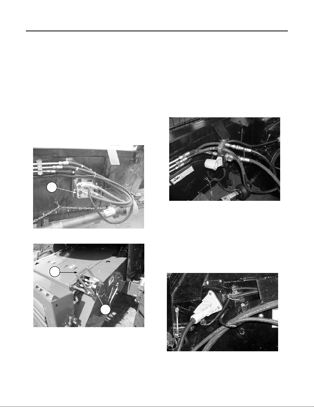
b) Attach hydraulics and electrical - Single
Point Connection (if equipped):
Clean all hydraulic hoses and couplings
before connecting to prevent contamination of
hydraulic system.
Align the single point header connector (A)
with the single point connector on the
combine (B) and lock by moving latch (C)
over-center.
NOTE: To install a header with single point
connector on a combine without a single point
connector, an adapter is required. See your
combine dealer.
A
Agco Single Point Connector – Header Side
C
B
Agco Single Point Connector – Combine Side
d) Connect hydraulic hoses to combine –
Without Single Point Connection:
Attach the ½ inch hydraulic hose from
the combine to the female coupler on the
header.
Attach the ½ inch hydraulic hose from
the header to the female coupler on the
combine.
Attach the 3/8 hydraulic hose (hold-down
line) from the header to the combine.
Agco Hydraulic Connections
(Non Single Point Connector)
e) Connect wiring harness – Without Single
Point Connection:
Attach extremity lighting wiring harness
to the combine receptacle, located on the
left side of the feeder house. Ensure
harness connector is pushed in far enough
to lock into receptacle.
Agco Electrical Connections
(Non Single Point Connector)
Form 169149 Revision E
18
Page 25

SECTION 3 – SETUP COMPLETION
3.2 CONNECTING HEADER/PICKUP TO
COMBINE – CASE IH &
NEW HOLLAND
NOTE: The operator of the combine should
be well trained in the use of combine controls.
Improper use of the combine could result in
damage to property or serious injury or
death.
NOTE: For New Holland combines built prior
to Model Year 2009, order B5614 – NH Auto
Header Height Sensor Kit from your MacDon
Dealer. Installation instructions are provided
with the kit.
a) Check to see that all header and feeder house
locking devices are open and ready for
engagement. Ensure handle (A) is positioned
so that hooks (B) can engage header lower
mounts.
B
A
b) On combines equipped with feeder house
lateral tilt, position the feeder house front
face to be square with feeder house floor.
c) Lower the combine feeder house so that the
feeder house saddle will just pass under the
upper beam of the header
d) Enter the header opening and lift the header
off the ground. The feeder house saddle and
header beam should now be firmly engaged.
HEADER UPPER BEAM
FEEDER SADDLE
Positioning on Combine
(May not be exactly as shown)
e) Raise the feeder house completely.
f) TURN OFF COMBINE ENGINE,
REMOVE THE KEY FROM THE
IGNITION, AND ENGAGE THE
FEEDER HOUSE SAFETY LOCK.
P00030
Engaged Feeder House Lock
(May not be exactly as shown)
P00029
Form 169149 Revision E
19
Page 26

SECTION 3 – SETUP COMPLETION
g) Push up on handle (A) on combine so that
hooks (B) from photo on page 2 engage
header lower mounting pins (K) on both
sides of the feeder house.
h) Be sure slot in lever (E) engages welded rod
on handle (A) to lock handle in place.
i) If hook (B) does not fully engage header
lower mounting pin (K) on both sides of the
feeder house when (A) and (E) are engaged,
adjust position of mounting pin (K) in slot as
required.
If force to engage handle (A) and lever (E) is
too loose or excessive, loosen bolts (G), and
adjust lock force as required. Re-tighten
bolts.
K
j) Connect Hydraulic Multi-coupler at (H) and
electrical harness at (J).
H
H
E
A
B
G
k) Disengage the feeder house locks and secure
in the storage position.
Disengaged Feeder House Lock
(May not be exactly as shown)
J
Form 169149 Revision E
20
Page 27

SECTION 3 – SETUP COMPLETION
3.3 FEEDERHOUSE WIDTH
CONVERSION
For John Deere, Case IH, New Holland and
Agco Combines, see the instructions supplied
with the mechanical completion package to
initially configure the header to suit your
combine. For Lexion combines, machines are
factory configured for narrow combine feeder.
Before use with a Lexion combine with wide
feeder house, the header must be reconfigured
using the supplied parts as follows:
Lexion – Narrow to Wide:
NOTE: These instructions can also be used to
convert a header configured for a John Deere
narrow feeder combine to a wide feeder house.
For Agco combines, see your dealer for
conversion instructions for the three available
feeder house widths.
a) Remove the two outer auger hand hole
covers to gain access to inside of auger.
Flight extension
c) Remove finger hole covers and add two
additional auger fingers and finger guides at
the next two open locations at both sides of
the auger (total of 4). These are shipped in
the document case at back of header.
d) Reinstall hand hole covers.
e) Remove lower stripper bar and stripper bar
extensions.
f) Move lower stripper bars outward one hole
so they are flush with combine feeder house
opening and bolt to the header floor.
Hand hole Covers
b) Remove the auger flight extensions. These
Extension bracket/bars
are the innermost pieces of flighting on each
side of auger center.
Form 169149 Revision E
21
Page 28

SECTION 3 – SETUP COMPLETION
g) Attach removed stripper bar extensions to the
outside of the back wall of header for
storage.
Stripper Bar Storage
h) Adjust stripper bars. See section 4.10 in this
manual.
i) Save all removed components for conversion
back to narrow opening at a later date if
necessary. In this case, the process described
above must be reversed.
3.4 DISENGAGING STORAGE BRACES /
REMOVING CYLINDER BRACES
NOTE: Before disengaging storage braces,
raise the header so wheels are just off the
ground.
Pickups are delivered with the storage and
cylinder braces engaged. Storage and cylinder
braces are located on each side of the pickup.
Before the pickup can be used, storage braces
must
be disengaged or machine will be
damaged.
P00659
Storage Brace Disengagement
a) Remove clevis pin.
b) Rotate storage brace upward into the
stiff-arm clevis.
Stiff Arm Clevis
Clevis Pin
P00677
c) Place clevis pin in stiff-arm clevis and
replace clip pin to secure brace upwards.
P00678
Storage Brace Disengaged
Form 169149 Revision E
22
Page 29

SECTION 3 – SETUP COMPLETION
Remove Cylinder Shipping Braces
NOTE: Do not remove yellow shipping braces
(D) until unit is laid down and arms are moved to
working position.
a) Support front of hold down assembly (E) and
remove the top lynch pins, washers and
cylinder pins securing braces (D), both sides.
b) Rotate braces down. Raise cylinders until
aligned with top pin position and reinstall top
cylinder pins, washers and lynch pins.
c) Remove bottom lynch pins and washers.
Remove braces and reinstall the washers and
lynch pins, both sides.
E
D
Remove Cylinder Shipping Braces
3.5 TESTING HYDRAULIC HOLD DOWN
NOTE: All testing should be performed
with the header/pickup in operating
position so that the wheels are on the
ground and the distance from the ground
to the center of the rear roller is about 14”
(356mm).
a) The hold down is controlled by the reel lift
control located in the combine cab. Activate
the control to lift the hold down. The
cylinders should begin lifting
simultaneously.
b) Lift the hold down completely to the top.
Continue to force the cylinders up for one to
two seconds to ensure the cylinders re-phase.
Both cylinders should be fully extended.
c) Lower the hold down. The cylinders should
lower at the same time and at the same rate.
It should take from 12 to 18 seconds for the
hold down to lower from the highest point.
d) Completely lower the hold down. The
cylinders should stop at the same time. It is
acceptable for the slave cylinder to remain
extended from 0 to 1/2” (13mm) when the
master cylinder is fully retracted.
Should the hydraulics not perform as above refer
to the procedures in the service section of this
manual.
Form 169149 Revision E
23
Page 30

SECTION 4 – ADJUSTMENTS
Pickup adjustments to be performed only
when:
Feeder house locks are engaged or
pickup is lowered to the ground.
Combine is shut off.
The key is removed.
All moving parts have stopped.
4.1 TIRE PRESSURE AND WHEEL
TORQUE
WARNING: An over inflated
tire could explode and cause
serious injury or death. Read tire
safety section before continuing.
a) Tire inflation: 8 to 10 PSI (55-69kPa)
b) Wheel bolt torque: 60 lb-ft
4.2 TEETH HEIGHT (WHEEL)
ADJUSTMENT
The proper height adjustment should be checked
to ensure the set-up of the pickup is correct. A
clearance of 1/2 inch (12mm) between the teeth
and the ground is recommended as an initial
setting. Line up the 6th cog from the bottom on
the pick up frame wheel plate with the
adjustment cog on the wheel spindle plate. See
following.
P00699
Recommended Initial Setting
1. Make sure tire pressure is in desired
range. (8-10 psi.)
2. Position the pickup rear roller height to
14“ above the ground (350mm). Check
tooth height at this time and proceed
with further adjustment if required.
3. Raise pickup until center of rear roller is
approximately 20” off of the ground.
4. Using a 3/4” wrench, loosen the
clamping bolt on one side of the pickup.
5. Using two 3/4” wrenches, move the
adjustment nut to the desired clearance.
P00686
Wheel Adjustment
P00686
Form 169149 Revision E
24
Page 31

SECTION 4 - ADJUSTMENTS
6. Tighten the clamping bolt to lock into
place
7. Repeat steps 4 to 6 for the other side.
Match the LH and RH wheel height using
the cogs on the wheel plates.
8. Adjust suspension.
NOTE: When wheel height is changed,
suspension should be adjusted as well.
4.3 SUSPENSION ADJUSTMENT
Wheels start
to lift off
ground
2
3
5
4
1
6
Suspension System Assembly and Parts List
(Illustration May Differ)
1. Lifter Adjustment Bolt (w/rubber stoppers)
2. Spring Bolt
3. Spring Bolt Locking Nut
4. Lifter Adjustment Bolt Locking Nut
5. Spring
6. Lifter Bracket
7. Mounting Bracket Plate
8. Channel Upright
a) Adjust tooth/wheel height. See previous
page.
b) Lower header until wheels just touch the
ground. [Rear roller approximately 20
inches (508 mm) above the ground.]
c) Tighten the spring bolt (2) evenly on both
sides until the wheels begin to lift off the
ground. Turn the spring bolt clockwise to
lift the wheels and counter clockwise to
lower the wheels.
NOTE: The friction in the gas shock
absorbers must be compensated for by lifting
the wheels during tightening and allowing
them to fall to their normal resting position.
The height of the wheels should be checked in
this manner after every 1/2 inch (12mm) of
spring adjustment.
d) Tighten the spring bolt-locking nut (3)
against the spring casting to prevent
loosening.
e) Raise header so wheels are approximately 6
inches (150 mm) off the ground.
8
f) Lower storage brace into engaged (float
lockout) position and insert clevis pin (see
7
Section 3.4). If pin does not go in, adjust
lifter adjustment bolt (1) so clevis pin can be
easily installed and removed.
g) Jam the lifter adjustment bolt-locking nut (4)
against the lifter bracket (6).
Note: If ground speed is above 7 mph
(11 km/h) it may be necessary to back off the
float to prevent the header from bouncing
excessively.
Note: During field operation, the rear roller
shaft should be at 14 inches (350 mm) above
the ground.
4.4 SPRINGWIRE/FIBREGLASS ROD
ADJUSTMENT
The spring wires and the fiberglass rods must be
set properly for different crop and conditions.
a) Remove the clevis and hitch pins and adjust
the spring wire tube so that the spring wires
protrude up through the fiberglass rods as
illustrated. This will protect the fiberglass
rods from becoming damaged by the spring
wire edges.
Form 169149 Revision E
25
Page 32

SECTION 4 - ADJUSTMENTS
NOTE: The purpose of the fiberglass rods is
to provide a smooth, even flow of material
under the auger and to the combine.
ADJUSTMENT POINT
D00046
Spring Wire and Fiberglass Rod Adjustment
P00701
Hold down Clevis and Hitch Pins
NOTE: To reduce shelling in heavy swaths, it
may be necessary to rotate the spring wires
completely out of the way.
P00171
Hold down Adjusted for Short Crops
P00172
Hold down Adjusted for Average Crops
P00173
Hold down Adjusted for Heavy Crops
NOTE: In some cases, if the hold down
assembly is moved substantially the
suspension should be retuned. Rotate the
spring wires clear before continuing to
operate.
4.5 DRAPER BELT TENSIONING
The pickup draper belts are installed and set
at the factory, however the draper belt
tension should be checked before operating.
A) Adjustment:
D00042A
Draper Belt Adjustment
Form 169149 Revision E
26
Page 33

SECTION 4 - ADJUSTMENTS
a) Loosen 1/2-inch carrier bracket bolts
shown in Pickup Belt Tensioner and
Carrier Bracket Bolts.
b) The belts are tensioned using 1/2 inch set
screw.
Carrier Bracket Bolts
Pickup Belt Tension Set Screws
c) Tension the belts until there is
approximately 1 1/2 inches of belt sag on
conventional Rake-Up and Swathmaster
pickups and SwathMaster Small Seed
pickups, and 2 inches of belt sag on
Rake-Up Small Seed pickups when
lifting midway between rollers. This
adjustment is shown in the Draper Belt
Adjustment For Conventional/Small Seed
Pickups.
d) Tighten 1/2-inch carrier bracket bolts.
P00685
P00679
NOTE:
1. When the pickup is mounted on the
combine, there should be visible sag in the
bottom side of the draper belt(s).
2. Some draper belts when new are very
tacky. Talcum or baby powder rubbed
into the belts may help to reduce the
tackiness. In addition, for the first few
hours of break-in, the belts may need to be
run looser than normal.
P00664
DO NOT OVER-TIGHTEN THE BELTS!
This can cause a number of problems:
1. Joining bolts can pull out of draper belts.
2. The center belts will slip on conventional
pickups.
3. The belts will crawl over the dividers.
4. The rollers or bearings could be damaged.
Any belts that fail from being over
tightened will not be covered under
warranty!
B) Belt Alignment–SwathMaster Small
Seed Pickups
If you are having trouble with the belts moving
sideways out of the pulleys and wearing the belt
edges, the following procedure should be
followed:
(a) First, check draper belt tension. An over
tensioned draper belt will tend to crawl
sideways more. If you are not sure, try
loosening the belt very slightly and then reevaluating.
Form 169149 Revision E
27
Page 34

SECTION 4 - ADJUSTMENTS
(b) Check that each side of the draper is
tightened evenly. If the drapers are not
tightened evenly, sometimes diagonal
ripples will appear running across the belt.
Generally, loosen the side that the ripples
are moving away from at the rear roller.
(c) If draper is tracking off to one side, loosen
the opposite side slightly. Make small
adjustments and watch tracking for a
minute before re-adjusting.
ADJUSTMENT TUBE
Form 169149 Revision E
28
Page 35

SECTION 4 - ADJUSTMENTS
4.6 PICKUP DRIVE BELT TENSION
Both Rake-Up and SwathMaster models come
equipped with self-tightening v-belts.
SwathMaster units have an additional method
to increase tension if required.
SwathMaster adjustment is as follows:
1. Remove drive shields. (See Service-Section
7)
2. Eliminate v-belt tension. (See Service-
Section 7)
3. Remove tension spring and reposition so
the extension is outside the mount bracket.
P00687
Factory
Setting
Extension Spring
Position for
Increased Tension
4. Tighten the tension spring hardware and
put v-belt back on sheaves.
4.7 SPEED CONTROL & HEIGHT
CONTROL
Depending of availability of these features on
various combine makes, the units may be
factory equipped with the speed control and
height control features. Refer to the following
for information to adjust and operate these
features.
Speed Control
In order for the speed control to operate properly
the sensor must be adjusted to read the target or
sprocket teeth.
The sensor height can be adjusted up or down by
loosening the 3/4” jam nuts with a wrench.
Adjust to a horizontal clearance of 3/16”(5mm).
Loosen the target sensor and slide it on the roller
shaft until the desired clearance is achieved
between the sensor and a sprocket tooth. When
proper alignment is achieved, tighten the lower
nut to lock the sensor into place and tighten the
setscrew to maintain target adjustment. Refer to
Section 5.1 for optimum pick up speeds and your
combine operator’s manual for the combine
portion of Dial-a-Speed operation.
ATTENTION: Loosen the lower nut first
when removing or adjusting the sensor.
Sensor Details
(Target May Not Be As Shown)
Height Control
NOTE: Never make any adjustments to the
AHC while the AHC unit is active in the
combine. Adjusting the AHC unit will cause
the feeder house to raise and lower.
Under normal conditions, the optimum pick up
height is achieved when the rear draper roller is
14” off of the ground. For normal conditions, set
the AHC so that it is in the neutral position when
D00126
Form 169149 Revision E
29
Page 36

SECTION 4 - ADJUSTMENTS
the pickup rear roller is at the 14” mark. See
following illustration.
Potentiometer Arm
Rotate Around
This Bolt
Mount Bracket
P00665
Components in Neutral Position
To set the AHC to this position:
1. The AHC switch in the combine should be
turned off and the draper belts properly
tensioned. (See Section 4.5) Each
subsequent time the belts are adjusted, the
AHC should be adjusted as well
2. Lift the header until the rear draper roller is
14” from the ground.
3. Loosen slightly, both nuts that hold the
potentiometer to the mount bracket. Rotate
the assembly around the left side bolt. The
right bolt will move along the slot. When
the arm on the potentiometer is
perpendicular to the potentiometer bracket
it is in the neutral position.
4. Retighten the nuts so that the potentiometer
is secure.
5. Refer to your combine operator’s manual
for the in-cab calibration procedure.
6. Test the function of the AHC. If the front
end of the pick-up goes up (as if going up a
hill) the header height should move up to
compensate. If the pick-up front goes
down (as if dropping into a hole) the
header should drop to compensate.
4.8 AUGER FINGER ADJUSTMENT
ATTENTION: Do not adjust fingers to
less than the minimum 1/4-inch clearance
to the header bottom.
Finger Adjustment Procedure
a) Loosen the clamping nut.
CLAMPING NUT
P00503
Finger Adjustment
b) Move the handle in the desired direction.
Counterclockwise = Fingers retract
Clockwise = Fingers extend
c) When the desired position is found,
tighten the clamping nut.
Form 169149 Revision E
30
Page 37

SECTION 4 - ADJUSTMENTS
4.9 AUGER ADJUSTMENT
The auger is a very important component in
getting a smooth, high capacity flow of crop
into the feeder house. Factory auger setting is
not intended to be field ready for all types of
crops. The auger must be adjusted for
different crop conditions.
The auger must also rotate freely without
touching the header floor or stripper bars.
Check the minimum factory clearance prior to
operation.
D00302
Factory Settings
(Illustration May Not Be Exactly as Shown)
A) Auger Clearance to Header Bottom
For heavy or bulky crops, a clearance of
25mm (1 inch) can increase header capacity.
For a lighter crop, a minimum clearance of
6mm (1/4 inch) will prove to be more
effective.
ATTENTION: If the auger contacts the
header bottom, excessive wear will occur to
auger and header bottom.
The clearance between auger and header
bottom can be adjusted as follows:
Adjust both ends of the auger to maintain a
uniform clearance across the width of the header.
a) Shields can remain in place.
b) Loosen clamp bolts protruding through
rubber stopper and sidewall.
c) Back off the lower auger height adjustment
nuts.
CLAMP BOLTS
ADJUSTMENT NUTS
P00491
Auger Height Adjustment Nuts
a) Turn the top nuts to raise or lower the auger
on both ends.
b) Turn the auger by hand and check for
clearance along the entire length of the auger.
c) Tighten the lower adjustor nuts.
Clearance between auger and strippers is to be
rechecked after the auger height setting has been
changed. See Auger Clearance to Stripper Bar.
B) Auger Forward/Rearward Adjustment
The auger can be moved forward or rearward to
adjust stripper clearance or improve augerfeeding performance. The factory settings will
prove very effective in most crop conditions. In
some cases of small grain crops, the auger may
Form 169149 Revision E
31
Page 38

SECTION 4 - ADJUSTMENTS
be moved further ahead or back in the auger
trough to improve performance.
Ensure that that the auger is adjusted evenly on
both sides.
a) Loosen the auger forward/rearward
adjustment nut on both sides. See
Forward/Rearward Adjustments.
b) Turn the rearward nut to pull the auger back
to reduce clearance.
c) Turn the forward nut to push the auger ahead
to increase the clearance.
d) Tighten the adjusting nuts to lock the auger
in the desired position.
`
REARWARD NUT
(HIDDEN)
FORWARD NUT
P00347
PIVOT BOLT
Forward/Rearward Adjustments
4.10 STRIPPER BAR ADJUSTMENT
The header is equipped with a pair of upper and
lower stripper bars.
DANGER: Lower header to the
ground or engage feeder house
locks, shut-off combine, remove
ignition key, and wait for parts to stop moving
before performing this adjustment
P00544
Upper and Lower Stripper Bars
The clearance between the auger and
stripper bars is set at the factory to a
minimum of 2mm (3/32 inch). Minimizing
the clearance of the auger and stripper bar
can reduce crop carry over.
The upper stripper bar bolts are accessible
from the top of the header.
A maximum reach of 16mm (5/8inch) can
be accomplished by using the slotted holes
in the upper stripper bar bracket and bar. If
more clearance is desired, see Auger
Forward/ Rearward Adjustment.
ATTENTION: If the auger comes in
contact with the stripper bar excessive
wear will occur. Disconnect the driveshaft
from combine and rotate auger by hand
to find the minimum clearance, than
complete all adjustments from that point.
Form 169149 Revision E
32
Page 39

SECTION 4 - ADJUSTMENTS
4.11 HEADER DRIVE CHAIN
ADJUSTMENT
DANGER: Lower header to the
ground or engage feeder house
locks, shut off combine, remove
ignition key, and wait for parts to stop
moving before performing this adjustment
NOTE: Check and adjust chain tension
after the first 3 hours of operation, and at
regular intervals thereafter.
Check header drive chain tension with a flat
screwdriver using the access hole on the left
side shield. See picture following.
P00480
Checking Chain Tension
The drive chain must be adjusted to give 1/2
inch to 3/4-inch deflection at the bottom with
approximately 10 lb (5kg) of force applied.
D00523
Drive Chain Deflection
Adjustment Procedure:
NOTE: It is not necessary to remove the side
panel for chain tension adjustment.
a) Loosen the 4 drive shaft bracket bolts only
enough to allow the bracket to slide in slots.
ATTENTION: Attempting to adjust chain
tension without loosening all 4 drive shaft
bracket nuts will damage the chain tension
bolt bracket.
P00525
Drive Shaft Bracket Bolts
b) Loosen the locknut on the chain tension bolt.
CHAIN
TENSION
BOLT
LOCK NUT
P00525
c) To relieve the chain tension, turn the chain
tension bolt counterclockwise.
d) To tighten the chain, turn the chain tension
bolt clockwise.
Form 169149 Revision E
33
Page 40

SECTION 4 - ADJUSTMENTS
e) Retighten the 4 drive shaft bracket bolts to
57 - 60 ft lb.
f) Tighten the lock nut to secure the chain
tension bolt.
g) Re-check chain tension as above.
Form 169149 Revision E
34
Page 41

SECTION 5
OPERATING INSTRUCTIONS
5.1 OPERATING SPEED
Performance of the pickup in various crop
and field conditions largely depends upon its
operating speed. If the swath is pushed
ahead, the pickup speed is too low and some
of the crop may remain unpicked. If the
swath is torn apart and is pulled toward the
combine header, the pickup speed is too high
and uneven combine feeding will occur.
Pickup operating speed is adjusted from the
combine cab by regulating oil flow to the
pickup hydraulic motor.
RAKE-UP: As a guide for initial settings of
pickup operating speed, a ratio of 11 RPM of
idler or drive rotor per 1 MPH of combine
ground speed can be used. For example:
when a combining speed of 5 MPH (8 km/h)
is selected, the rotors shall run at 11 x 5 = 55
RPM: at 3.5 MPH (5.6 km/h), the rotors shall
turn at 11 x 3.5 = 38.5 RPM.
If a shaft tachometer is available, set the rear
roller shaft speed at 73 RPM per 1 MPH of
combine speed. For example: when a
combining speed of 5 MPH (8km/h) is
selected the rear roller shaft shall run at 73 x
5 = 365 RPM.
SWATHMASTER: As a reference for
initial settings of pickup operating speed, a
ratio of 13 RPM of the front draper belt per 1
MPH of combine ground speed can be used.
For example: when a combining speed of 5
MPH (8km/h) is selected, the front draper
belt shall run at 13 x 5 = 65 RPM; at 3.5
MPH (5.6km/h) the draper belt shall run at
13 x 3.5 = 45.5 RPM.
If a shaft tachometer is available, set the rear
draper - rear roller shaft speed at 73 RPM per
1 MPH of combine speed. For example:
when a combining speed of 5 MPH (8km/h)
is selected the rear draper - rear roller shaft
shall run at 73 x 5 = 365 RPM.
In general, maximum pick up speed for picking
conditions shall be selected so that the swath is
always pushed slightly ahead.
IMPORTANT: The maximum front draper belt
speed on a SwathMaster pickup should not
exceed 104 RPM equivalent to a combine speed
of 8 MPH. The maximum idler or drive rotor
speed on a Rake-Up pickup should not exceed
88 RPM equivalent to a combine speed of 8
MPH. Over speeding the pick up may cause
premature wear of drive components and
minimize performance
ATTENTION: Do not over-speed pickup.
Over-speeding pickup will cause premature
wear of drive components and adversely
affect pickup performance.
HEADER: The header is supplied with an auger
drive sprocket to match your combine. In certain
crops, a higher or slower auger speed may be
desired. Contact your dealer for available
sprocket options.
Form 169149 Revision E
35
Page 42

SECTION 5 – OPERATING INSTRUCTIONS
5.2 OPERATING HEIGHT
A) Header Operating Height
Lift the header until the center of the rear draper
roller is 14" (356mm) above the ground. This is
an appropriate header operating height.
D00049
Proper Header Height
(Rake-Up Shown)
B) Pickup Operating Height
Depending on field conditions, it may be
necessary to either increase or decrease the
amount of clearance between the teeth and the
ground. Two general symptoms will indicate
that this adjustment is necessary:
a) The pickup leaves material unpicked in the
field. This is an indication that the teeth are
too high.
b) The pickup teeth are wearing quickly or are
picking up dirt and stones. This indicates
that the teeth are set too low.
NOTE: After adjusting tooth height, the
suspension system must be retuned for
optimal performance. See Suspension
Adjustment.
5.3 HOLDDOWN POSITIONING
Hold down position is important to the
performance of the pickup and must be
adjusted according to crop conditions. The
spring wires on the front of the pick up are
designed to keep the swath from forming a
ball or rolling sideways in front of the teeth.
Fiberglass rods hold the swath in contact
with belts and guide the crop under the
auger. Ideally, the spring wires should
touch the top of the swath to keep it in
contact with the pickup teeth. Constant
down pressure on the crop will assist in
pickup performance.
A) Hold down Height Adjustment
The hydraulic hold-down option allows you
to fine tune the hold-down position using the
combines reel height adjust.
NOTE: In the case of plugging the feeder
house, raise the hold-down out of the way
before using the reverser.
DANGER: Lower header to
the ground or engage feeder
house locks, shut-off combine,
remove ignition key, and wait for parts to
stop moving before performing this
adjustment
D00002
Hydraulic Lift
Form 169149 Revision E
36
Page 43

SECTION 5 – OPERATING INSTRUCTIONS
B) Hold-down Orientation
The spring wires and the fiberglass rods must
be set properly for different crop and
conditions.
b) Remove the clevis and hitch pins and
adjust the spring wire tube so that the
spring wires protrude up through the
fiberglass rods as illustrated. This will
protect the fiberglass rods from becoming
damaged by the spring wire edges.
NOTE: The purpose of the fiberglass rods
is to provide a smooth, even flow of
material under the auger and to the
combine.
ADJUSTMENT POINT
D00046
Spring Wire and Fiberglass Rod Adjustment
P00701
Hold-down Clevis and Hitch Pins
NOTE: To reduce shelling in heavy swaths, it
may be necessary to rotate the spring wires
completely out of the way.
P00171
Hold-down Adjusted for Short Crops
P00172
Hold-down Adjusted for Average Crops
P00173
Hold-down Adjusted for Heavy Crops
NOTE: In some cases, if the hold-down
assembly is moved substantially the
suspension should be retuned. Rotate the
spring wires clear before continuing to operate.
Form 169149 Revision E
37
Page 44

SECTION 5 – OPERATING INSTRUCTIONS
5.4 RADIAL PIN CLUTCH
(On all header drive shafts)
Every header is equipped with a driveshaft,
which contains a radial pin clutch. This clutch
emits a rattling sound and pulsating motion when
slippage occurs.
P00174
Radial Pin Clutch
The purpose of this clutch is to provide
protection against overload. When an obstruction
encounters the auger and creates an overload, the
clutch will slip notifying the operator of a
problem. Frequent slippage for more than two or
three seconds may result in clutch damage.
ATTENTION: Prolonged operation of the
header with the clutch slipping will cause
damage to the header and/or clutch.
5.5 DISCONNECTING FROM
COMBINE
ATTENTION: Always lock the storage
brace prior to disconnection. Failure to
lock storage braces will result in difficulty
reconnecting the header to the combine.
TIP: Engaged braces for long trips from
field to field on rough terrain will prevent
the pickup from bouncing.
a) Remove the clevis pins from storage
clevis.
b) Pull storage braces downward out of
storage brace holders and place in locking
position.
Clevis Pin
P00677
Storage Brace - Engaged
c) Reinstall the clevis pins in storage braces.
To ease pin installation it may be
necessary to slightly raise or push down
on pickup wheel.
d) Move unit to storage location.
e) Disconnect all hydraulics and wiring
between the header and combine. Some
combine models use a multi function
coupler that disconnects the hydraulics,
Form 169149 Revision E
38
Page 45

SECTION 5 – OPERATING INSTRUCTIONS
electrical wiring and feeder house locks
simultaneously. The coupler is to be
unlocked and stored in the storage
bracket. Other models have a coupler
system for the hydraulics and separate
electrical harness connections.
f) Remove the drive shaft from the feeder
house and place it on the storage bracket.
g) Engage the feeder house lock.
h) Unlock the lower hookup points on
header.
i) Disengage the feeder house lock.
j) Lower the feeder and slowly drive out of
the feeder house opening of the header.
5.6 UNPLUGGING THE AUGER
Occasionally the auger may become plugged
and will require unplugging.
To unplug feeder house or auger with
combine reverser:
a) Refer to your combine manual for
operating instructions.
b) Stop combine forward travel.
c) Shut off pickup unit.
d) Raise hold down all the way up.
e) Engage reverse mode.
NOTE: To prevent damage to the pickup
motor, DO NOT engage the feeder reverser
for more than 5 seconds if the feeder and
auger will not turn.
ATTENTION: Pickups cannot run in
reverse. Any attempt to run pick up in
reverse will seriously damage pick up
and/or pick up motor.
Form 169149 Revision E
39
Page 46

SECTION 6 –
MAINTENANCE/LUBRICATION
Read and follow all safety procedures in the
beginning of the Operators manual.
WARNING: Take Extreme
caution around escaping hydraulic
fluid. Release all pressure in the
system before servicing or inspecting
leaking lines. Hydraulic fluid under high
pressure can penetrate the skin and cause
serious injury. Never use your hands to
inspect lines. Seek immediate medical
attention if fluid penetrates your skin.
DANGER: Lower header to the
ground or engage feeder house
locks, shut-off combine, remove
ignition key, and wait for parts to stop moving
before performing this procedure.
6.1 FIRST TIME USE – MAINTENANCE
Inspect the wheel bolts for looseness. Torque
after first 10 hours of use. (60 lb-ft)
6.2 DAILY MAINTENANCE /
LUBRICATION (10 hours)
Check tire pressure. The pressure should be 8
– 10 PSI. (55-69 kPa)
Check for loose fasteners.
Grease header drive shaft daily as per
lubrication chart.
Inspect teeth for straightness.
Check SwathMaster Small Seed belt
guides for wear.
6.3 WEEKLY MAINTENANCE /
LUBRICATION (50 hours)
Oil chain and sprockets with chain lube.
Check header drive chain tension.
Check wheel bolt tightness.
Check draper belt tension.
Inspect bearings and seals.
RAKE-UP
Check that the pickup drive belt
tensioner oscillates freely. Apply a spray
lubricant to the idler arm pivot point.
Check that the 1/2 inch x 1 1/2 inch
UNC bolt that secures the drive rotor to
the large gearbox is tight. Also, check
that the 1/2-inch x 1 1/2 inch UNC bolt
that secures the idler rotor to the frame is
tight. These bolts may work loose even
though they have been drilled and
secured with wire.
NOTE: Neglecting to keep the idler and
drive rotor retaining bolts tight can result
in catastrophic failure of the pickup drive
system. Failures of this nature are easily
prevented with proper maintenance and
as such are not covered by warranty.
Form 169149 Revision E
40
Page 47

SECTION 6 – MAINTENANCE/LUBRICATION
D00047 D00048
Drive Rotor Idler Rotor
Rake-Up Attachment Bolts
Check the setscrews for tightness on the
main gearbox pulley.
P00053
Rake-Up Main Gear Box Pulley Set Screws
6.4 YEARLY MAINTENANCE /
LUBRICATION (100 hours)
Perform all daily and weekly procedures.
RAKE-UP & SWATHMASTER
If pickup is equipped with the height
control (AHC or AHHC), lubricate all
height sensor pivot points seasonally.
Check v-belt condition.
RAKE-UP
The six small gearboxes at the drive end of the
pickup require seasonal lubrication. Remove
the pipe plugs and fill with NLGI Grade 000
extreme pressure, semi-fluid lithium grease,
such as Mobilux EP 023, Petro-Can Precision
XL EP000, or Chevron Dura-Lith EP000. With
the header raised and secured, add grease until
level with plug. Do one gearbox at a time then
rotate the next one to the front.
Inspect all gearboxes for signs of wear.
P00072
Small Gear Box Lubrication
P00259
P00259r
Main gearbox Plug
The main gearbox is filled at the factory with
14.4 Fluid Oz (425 ml or 0.112 US gal) of
NLGI Grade 000 extreme pressure, semifluid lithium grease, such as Mobilux EP
023, Petro-Can Precision XL EP000, or
Chevron Dura-Lith EP000. Lower viscosity
oils may leak out of the gearbox.
Continued next page…
Form 169149 Revision E
41
Page 48

SECTION 6 – MAINTENANCE/LUBRICATION
NOTE: To ensure that the proper amount of
grease has been added, remove the plug and
insert a wire into the hole. With the pickup in
the field position the grease level should be
1 1/2” (38mm) below the lid of the gearbox.
HEADER
Clean and grease the header drive shaft
splines once a year. This will prevent
excessive corrosion from forming.
P00338
Header Drive Shaft
Form 169149 Revision E
42
Page 49

SECTION 6 – MAINTENANCE/LUBRICATION
6.5 LUBRICATION POINTS
E
B
D
C
A – Drive Shaft
B – Six Small Gear Boxes (Mirror Model shown)
C – Main Gearbox (Mirror Model Shown)
P00667
B
A – Drive Shaft
B – Height Control Sensor
A
Rake-Up Lubrication Points
D– Belt Tension Idler Arm
E – Height Control Sensor (If equipped)
F – Header Drive Chain and Sprocket
A
SwathMaster Lubrication Points
C – Header Drive Chain & Sprocket
(If equipped)
P00079
F
C
Form 169149 Revision E
43
Page 50

SECTION 6 – MAINTENANCE/LUBRICATION
H A1
NOTES:
A2
A3 A4
Drive Shaft Lubrication Points
A5
A1 U-Joint
P00078
A2 Shield Bearing
A3 Telescoping Tube
A4 Shield Bearing
A5 U-Joint
P00178
H Clutch
Form 169149 Revision E
44
Page 51

SECTION 6 – MAINTENANCE/LUBRICATION
6.6 MAINTENANCE / LUBRICATION CHART / GREASE SPEC
Read Maintenance/Lubrication Section for proper procedures. Use this chart as a quick reference only.
GREASE SPEC: Use SAE Multi-Purpose Grease per the following:
All locations except Driveline slip joints
Driveline slip joints – High Temp. Extreme Pressure (EP) Performance With 10% Max Molybdenum
GEAR LUBE (Rake-Up): NLGI Grade 000 extreme pressure, semi-fluid lithium grease, such as
1 Drive Shaft Splines 100 100
2 Drive Shaft (Points A1, A3, A5) 50
3 Drive Shaft Clutch 50
4 Header Drive Chain & Sprocket 50
5 Six Small Gear Boxes (Rake Up Only) 100
6 Main Gear Box (Rake Up Only) 100
7 Belt Tension Idler Arm (Rake Up Only) 50
8 Tire Pressure * 100
9 Loose Fasteners 10
10 Hose Leaks 10
11 Wheel Bolts 100
12 Drive Chain Tension * 50
13 Draper Belt Tension * 50
14 Idler Rotor Bolt 50
15 Drive Rotor B olt 50
16 Bearing Damage 100
17 Teeth Wear 100
18 Gear Box Wear 100
19 Worn Paint Spots 100
20 Cleaning of Units 100
21 Wear Inspection 100
22 Drive Shaft (Points A2, A4) 10
23 Belt Guide (SwathMaster Grass Seed) 50
24 Height Control Sensor Pivot Points 100
* Check first 10 hours of operation, and then at regular chart intervals.
Disulphide (NLGI Grade 2). Lithium Base
Mobilux EP 023, Petro-Can Precision XL EP000, or Chevron Dura-Lith EP000.
Service to Perform
– High Temp. Extreme Pressure (EP2) Performance With 1%
Max Molybdenum Disulphide (NLGI Grade 2). Lithium Base
Frequency In Hours
Grease
Lubricate
Check
Clean
Change
Form 169149 Revision E
45
Page 52

SECTION 7
SERVICE
7.1 ATTACHING PICKUP TO HEADER
DANGER: Lower header to the
ground or engage feeder house
locks, shut-off combine, remove
ignition key, and wait for parts to stop moving
before servicing.
ATTENTION: Do not lift the header
without the header braces properly installed.
Attempting to lift the header without header
braces will damage the pick up or header.
Parts damaged due to improper handling are
not covered by warranty.
Positioning on Header
a) Support the pickup with the rear roller at
approximately 14 inches (356mm) above the
ground with wooden blocks located under the
shock tubes. See following drawings.
Installing Rake-Up onto the Header
D00332
Installing SwathMaster onto the Header
13 FT. HEADER: With the header mounted
on the combine, position the header cutter bar
under the pick up mounting bracket for 12ft
pickups and above the mounting bracket for
14ft pick ups.
Position the header such that the left and right
hand channel uprights on the pickup frame are
equal distances from the sides of the header.
On 14ft pick ups, the channel uprights are
outside the header.
See illustrations next page.
D00333A
Form 169149 Revision E
46
Page 53

SECTION 7 – SERVICE
D00268A
Mount Bracket Orientation
15 FT. HEADER: With the header mounted
on the combine, position the header cutter bar
above mounting brackets for 16ft pick ups.
Position the header such that the left and right
hand channel uprights on the pickup frame are
equal distances from the sides of the header.
On 16ft pick ups, the channel uprights are
outside the header.
D00062
Centering the Rake-Up on the Header
(Rake-Up Frame not exactly as shown)
d) Loosely bolt the header braces to the channel
uprights and the header sidewall.
P00386
Mounted Header Brace
e) Bolt the mounting brackets to the cutter bar
using the 7/16-inch carriage bolts, spring lock
washers, and nuts provided. There are three
bolts for each side of the pickup. The
clearance between the cutter bar and rear
roller can be increased, if desired, by
positioning the shim between the cutter bar
and mount bracket. (True only for 14ft pick
up on 13 ft. headers and 16ft pick up on 15 ft.
headers.)
NOTE: It may be necessary to shift the
pickup slightly off center to align the
mounting bracket and the cutterbar with the
holes.
f) Make sure mounting bracket is secure and
flush to cutter bar. Tighten all header brace
bolts. Lift the header and remove the wooden
blocks.
Form 169149 Revision E
47
Page 54

SECTION 7 – SERVICE
7.2 OPENING HEADER SIDE PANELS
John Deere / Lexion / Agco:
To remove left panel, unscrew bolts and lift up
on panel.
P00551
Left Hand Shield: John Deere / Lexion / Agco
To remove right panel unscrew bolts and pull
away from header.
P00552
Right Hand Shield: John Deere/Lexion/Agco
NOTE: It is not necessary to remove panels
to perform adjustments on units. See 4.11
Header Drive Chain Adjustment.
Case IH / New Holland:
D
a) To open shield, push release tab (D) towards
rear of machine. Latch will release top of
shield.
b) Swing shield down and away from machine
to allow enough room to lift it. Lift shield
enough to disengage lower hooks and
remove the shield.
c) To close shield, engage shield hooks (E) in
slots at bottom of frame.
d) Swing shield up to engage upper tab latch
mechanism (F).
e) Close side panel until it is securely latched.
F
Form 169149 Revision E
48
E
Page 55

SECTION 7 – SERVICE
7.3 REMOVING PICKUP SHIELDS
SWATHMASTER
Upper Ridge
Thumbscrews
Removal:
P00689
a) Unscrew the upper and side
thumbscrews.
b) Grabbing hold of the upper ridge,
pull off the Shield.
Installation:
a) Position the shield onto the brackets
and slide back and forth until circular
indentation falls into the rear guide.
Rear Guide
P00700
b) Tighten the thumbscrews.
RAKE-UP
Remove four 5/16” bolts and pertaining
hardware.
P00688
Rake-Up Drive Shield Removal
7.4 HYDRAULIC SYSTEM
CAUTION: High-pressure
hydraulic oil can cause serious
injuries such as burns, cuts, and
tissue damage! Always take
precautions when working with hydraulic oil.
Wear safety goggles, gloves and thick
clothing. Seek immediate medical attention if
cut or burnt.
ATTENTION: On some combine models,
hydraulically driven after-market chaff
spreaders are connected to the pickup drive
hydraulic pump. When the pickup is sharing
the drive with a chaff spreader, the pickup
performance can be adversely affected or
damage may occur to the hydraulic system. If
the hydraulic motor on the pickup is mounted
in series in front of the chaff spreader,
backpressure from the chaff spreader may
cause damage to the pickup motor. The
pickup motor warranty is voided under these
conditions.
Form 169149 Revision E
49
Page 56

SECTION 7 – SERVICE
NOTE: Swath Master units use the 101-1011
(MacDon #184266) orbit motor (ORB ports).
Rake-Up units use 101-1010 (MacDon
#184265) orbit motor (ORB ports). These
motors perform well on most combines. On
combines with less flow capacity the 101-1009
(MacDon #184264) orbit motor (ORB ports)
may be required to increase pickup speed.
A) Hydraulic Motor Installation/Removal
RAKE-UP
Removal:
a) Lower the pickup to the ground shut off
combine and remove key.
b) Remove the two hydraulic lines from the
motor if the motor is being replaced or
repaired. Be sure to have some rags and a
bucket to catch the oil in the hoses.
c) Remove all shields that will interfere with
this procedure.
d) Loosen the setscrew on the motor coupler.
e) Extract the two flange head bolts until they
contact the motor.
f) Proceed to extract the bolts one revolution at
a time until the motor is removed.
g) Remove the two flange head bolts and place
aside.
h) Remove the two ¼” hex head bolts and
thread them into the previously removed
flange head boltholes until they contact the
hub.
i) Rotate each bolt one revolution at a time
until the hub releases.
j) Remove the coupler and hub and / or pulley.
Installation:
a) Install the coupler with hub or pulley onto
the roller shaft. Be sure the coupler
bottoms out with the end of the roller
shaft.
b) Lock into place with the 1/4" bolts and
spring lock washers. When tightening the
1/4" bolts, alternate several times from one
bolt to the other, until both bolts are
equally secure. Return the ¼” flange head
bolts to their original location.
c) Install the hydraulic motor with key into
the hydraulic motor coupler and lock into
place with the setscrews.
SWATHMASTER
Removal:
a) Remove shield. See previous section.
b) Disconnect hoses. Oil will leak from
hoses upon disconnection.
c) Remove v-belt. (See v-belt removal)
d) Remove the ½” bolt, spring lock washer,
retaining washer, and arm extension.
e) Next step is Motor/Sheave removal. There
are two methods of breaking hub away
from the coupler.
I) Large chisel & hammer.
1 Using 7/16” wrench or socket,
remove the two 1/4” bolts and
spring lock washers.
2. Position a 1” or 1 1/4” chisel
between the hub and sheave.
Gently tap alternate sides until hub
comes free. Do not contact the
coupler-damage may occur.
3. Taking hold of the sheave, give a
sharp pull. The motor sheave and
Form 169149 Revision E
50
Page 57

SECTION 7 – SERVICE
coupler should come free. Use a
rubber mallet if necessary. Do not
lose the key.
II) 7/16” Wrench or Socket (slower)
1. Using a 7/16” wrench, remove the
1/4” bolts and thread them into the
second set of holes in the hub until
they contact the sheave.
2. Turn each bolt a half turn at a time
until the hub releases.
3. Taking hold of the sheave, give a
sharp pull. The motor sheave and
coupler should come free. Use a
rubber mallet if necessary. Do not
lose the key.
f) Flip the motor up on end with sheave
upward.
g) With rubber mallet, gently tap alternate
sides of the sheave until it break free.
h) Place a chisel in the slot of the coupler and
slightly spread it open.
i) Pull the motor off of the coupler. Do not
lose the key.
j) Remove the torque arm and hose fittings if
replacing the motor.
Installation:
a) Place the torque arm onto the motor and
secure.
b) Place the key in the slot of the roller shaft.
c) Slide the hub onto the shaft-shouldered
end first.
d) Position the motor coupler onto the shaft
while aligning the key with the slot. Tap
on until it bottoms out.
e) Loosely place the sheave onto the coupler.
f) Slide the motor and torque arm into the
coupler until it hits the roller shaft. Be sure
the key and key way is aligned.
g) With a rubber mallet tap the sheave onto the
coupler until it is firmly seated.
h) Place the 1/4” bolts into the non-threaded
holes and align with the threaded holes on
the sheave. Tighten until snug.
i) Using a 7/16” wrench or socket, alternate
tightening the bolts a bit at a time until a
maximum torque of 9lb ft (11Nm) is
achieved.
j) Rotate torque arm to align with arm
extension shaft. Install arm extension,
retaining washer, bolt and hardware.
k) If installing new motor, install hose fittings
from previous motor.
l) Install the v-belt onto the sheave and activate
belt tensioner.
m) Install hoses onto the motor and secure.
n) Install shield.
P00690
Hydraulic Motor Installed
Form 169149 Revision E
51
Page 58

SECTION 7 – SERVICE
B) Hydraulic Cylinder(s) Replacement
The hold down employs a single-acting master
and slave circuit for raising and lowering the
hold down. The operation of the lift can be
adversely affected by factors such as air in the
system. It is suggested that the following
procedure be used to ensure proper operation of
the hold down when servicing the unit.
Removal/Installation Procedure
a) Lower the hold down completely down,
shut off combine and remove key.
b) Release all hydraulic pressure in the
system.
c) Remove all hydraulic hoses from the
cylinder(s) being removed. Be sure to
have a container and rags to catch any
escaping hydraulic oil.
d) Remove the two hitch pins and washers
that hold the cylinder on the pickup.
e) With the help of a second individual who
is slightly lifting up the hold down, pull
off the cylinder and install the new one.
NOTE: There should be a washer on the
outer sides of the cylinder.
f) Install the washers and hitch pins.
g) Complete Fitting Transfer/Installation if
replacing cylinder.
Fitting Transfer/Installation
You will now have to either transfer the old
fittings over from the removed cylinder or install
the new fittings onto the new cylinder. The
following will instruct you on the proper
procedure:
Master Cylinder
a) Remove the two 90-degree elbows and
the orifice from the old master cylinder.
b) Screw the orifice into the lower port of
the master cylinder. Turn until the orifice
bottoms out. Then screw one ORB/JIC 90
degree elbow into the lower port of the
master cylinder. Continue screwing in the
elbow until you feel a slight resistance
then stop. Orient the elbow tip upward
approximately 30 degrees outward and
tighten the jam nut.
c) Screw in the second ORB/JIC elbow into
the upper port of the master cylinder until
you feel a slight resistance then stop.
Orient the tip of the elbow straight toward
the cylinder rod and tighten the jam nut.
d) Connect the hold down hose to the upper
90-degree elbow on the master cylinder.
When tightening the hose ensure the hose
goes up from the elbow and does not fall
to the side.
e) Connect the header hose to the lower 90-
degree fitting on the master cylinder.
Master Cylinder
Note: The ports of the master and slave
cylinders point downwards on a
SwathMaster pickup and face upwards on
a Rake-Up pickup.
P00691
Form 169149 Revision E
52
Page 59

SECTION 7 – SERVICE
Slave Cylinder
a) Remove the 90-degree elbow and bleed
plug from the old slave cylinder.
b) Screw in the ORB bleed plug into the
upper port of the slave cylinder. Tighten
snug.
c) Screw in the 90-degree ORB/JIC elbow
into the lower port of the master cylinder
until you feel a slight resistance then
stop. Orient elbow tip toward the rod end
of the cylinder and approximately 30
degrees outward and tighten the jam nut.
d) Connect the hold down hose to the lower
90-degree elbow on the slave cylinder.
Slave Cylinder
(SwathMaster pickup shown)
NOTE: Testing is required after any
servicing is done to the hold down
hydraulic system Refer to Testing
Hydraulic Hold down for procedure.
C) Hose Routing and Clamping
Hold down hoses/steel lines run under
and across the fiberglass rod flat bar
between the cylinders. These require
proper clamping and routing to avoid
hose damage.
P00692
P00694
Properly Routed Hold down Hose
The hoses from the hydraulic motor and
cylinder running to the header also
require proper clamping and orientation
SWATHMASTER
SwathMaster hoses are secured to the idler
bracket with a plastic hose clamp.
P00693
SwathMaster Hose Clamping
D) Pickup to Header Hydraulic Connections
a) The pickup motor hoses connect to the steel
lines secured to the header sidewall.
b) The hold down hose is to be looped and
connected to the 3/8 inch steel line on the
header.
Form 169149 Revision E
53
Page 60

SECTION 7 – SERVICE
pply
pply
y
NOTE: The hose on the motor port closest to
the header is the supply line and the hose
furthest from the header is the return line.
Identification of the header lines is as follows:
Lower 3/8 inch line is the hydraulic
hold down line
Middle line is the motor return line
Upper line is the supply line
NOTE: Hold down hose must have sufficient
slack and be oriented properly to prevent
damage.
Hold down
Return
Suppl
Return
Supply
P00581
Rake-Up Orientation
Return
Hold down
Supply
Return
Su
P00695
SwathMaster Orientation
c) All steel lines are firmly mounted to the
header wall with clamps.
Hose Clamping
JOHN DEERE 60 SERIES MODELS
P00493R
Hydraulic/Electrical Connection
Return
Su
Hold down
P00582R
Orientation of Hydraulic Lines
A. Coupler Removal and Installation:
P00585
1) Remove snap ring.
2) Remove coupler.
3) Remove coupler fitting.
4) Install coupler fitting into new coupler.
5) Place coupler into the socket and
replace snap ring.
Form 169149 Revision E
54
Page 61

SECTION 7 – SERVICE
y
y
B. Electrical Connector Removal and
Installation
P00586R
1) Remove snap ring.
2) Remove connector.
3) To install connector, reverse steps.
C. Removal and Replacement of Locking
Bushings
Bushing
Shoulder
P00587
1) Unscrew shoulder bolt.
2) Remove and replace bushing.
3) Apply temporary thread locking
compound to shoulder bolt thread.
Tighten bolt to a torque of 30Nm.
4) Check bushing for free rotation.
bolt
JOHN DEERE 50 SERIES MODELS
Hold downElectrical
P00584
Electrical and Hydraulic Connections
LH Side
Motor Suppl
Motor Return
P00583
Hydraulic Connections
RH Side
CLAAS / LEXION
Return
Suppl
Hydraulic/Electrical Connection
NOTE: When connecting/disconnecting
hydraulic fittings two wrenches should be
used.
Form 169149 Revision E
55
Page 62

SECTION 7 – SERVICE
AGCO
Supply
Return
Hold-down
Hydraulic/Electrical Connection
E) Hydraulic Hold Down Troubleshooting
To correct uneven cylinder operation, follow the
instructions in this section step by step to
troubleshoot its operation.
Prior to troubleshooting the hydraulics,
additional orifice should be obtained from your
local dealer. The procedures below indicate
adjustments to perform as needed.
Problem 1: Slave Cylinder Remains
Extended More Than 1/2 inches
(13mm) When the Hold down is
Fully Lowered.
Probable Solution:
Bleed Hydraulics
a) Bleed the hydraulics as described in the bleed
procedure.
b) Retry the hold down.
c) Check for improvement.
d) Repeat two or three times as necessary.
Problem 2: Master Cylinder Lags Behind
Slave Cylinder on Descent and
Jumps Ahead of Slave When
Lifting.
Probable Solution(s):
Remove Mechanical Obstruction
Bleed Hydraulics
Install Larger Orifice in Bottom of
Master Cylinder.
Service Parts:
1/16 inch Orifice (Part # 01-10922-01)
1/32 inch Orifice (Part # 01-10922-02)
a) Check for a reason for mechanical
binding.
b) Bleed the hydraulics as described in the
Bleeding of Hydraulics.
c) Retry the hold down.
d) Check for improvement.
e) Repeat two times if required.
If this does not work, then replacing the
orifice in the master cylinder may fix the
problem.
a) Loosen and remove the hose at the
bottom of the master cylinder. Keep rags
handy to clean up leaking hydraulic oil.
b) Loosen and remove the elbow from the
bottom of the master cylinder.
c) Using a large bladed flat screwdriver,
loosen and remove the orifice from inside
the bottom port of the cylinder.
d) Install the 1/16-inch orifice in the bottom
port. Do not over tighten.
e) Replace the elbow and the hose.
f) Bleed the hydraulics as described in the
Bleeding the Hydraulics.
g) Repeat two or three times as needed.
h) Check the overall operation of the hold
down.
Form 169149 Revision E
56
Page 63

SECTION 7 – SERVICE
Installing the 1/16-inch diameter hole
orifice will likely prevent the master
cylinder from lagging.
F) Bleeding the Hydraulics
In order for the hydraulics to perform
properly, all or most of the air must be
removed from the system. The following
procedure provides the easiest method of
bleeding the hydraulics. The hydraulics
should be bled after initial installation, if the
unit has sat for a significant period of time,
and if adjustments are needed to the
hydraulics.
CAUTION: High-pressure
hydraulic oil can cause serious
injuries such as burns, cuts, and
tissue damage! Always take
precautions when working with hydraulic
oil. Wear safety goggles, gloves and thick
clothing. Seek immediate medical
attention if cut or burnt.
a) The hold down is controlled using the
reel lift control located in the combine
cab. Fully raise the hold down.
b) Engage the hold down safety locks.
Ensure that the lock is fully rotated over
center so that it will not slip forward.
c) Lower the hold down so that it comes to
rest on the safety locks. (This serves to
relieve the hydraulic pressure in the
lines).
d) Hold the plastic pail so the lip of the pail
is underneath the bleed plug and so that a
stream of oil shooting out of the plug will
go into the pail.
e) Loosen the small bleed screw on the end
of the bleed plug with a 1/4-inch wrench.
f) Have someone activate the hydraulics. The
hold down may lift slightly and a stream of
oil will come from the bleed screw.
g) Run oil from the bleed screw until it is a
steady clear stream. Have the operator stop
activating the hydraulics and tighten the
1/4inch bleed screw.
h) Fully raise the hold down again.
i) Disengage the safety locks.
j) Lower the hold down.
Bleeding of Hydraulics
P00696
P00696
Form 169149 Revision E
57
Page 64

SECTION 7 – SERVICE
7.5 DRIVE SHAFT INSTALLATION
WARNING: DO NOT begin to
perform any service procedure until
combine is lowered to the ground or
feeder house locks are engaged,
combine is shut off, the key is
removed and all moving parts have
stopped.
The drive shaft is to be installed after the
header/pickup is attached to combine. Installing
the drive shaft requires the following steps:
a) Engage the feeder house lock or lower the
header completely down.
b) Shut off engine and remove the key from the
ignition.
c) Take the clutch end of the drive shaft, pull
back the locking plate and slide it onto the
drive shaft of the header
d) Release the locking plate and continue
sliding it on to the header shaft until it clicks
into place. Pull back to ensure that drive
shaft is locked into place.
P00047
Drive Shaft to Header Installation
(Illustration May Differ)
e) Take the opposite end of the drive shaft,
pull on the quick disconnect slide collar
and slide it onto the shaft of the
combine.
f) Release the collar and continue sliding it
onto the combine shaft until the yoke
locks into place. Pull back to ensure that
drive shaft is locked.
P00048
Drive Shaft to Header Installation
(Illustration May Differ)
g) Attach both drive shield chains together.
h) Take the single chain clip and attach to
back of header.
P00049
Chain Clip Attachment
Form 169149 Revision E
58
Page 65

SECTION 7 – SERVICE
NOTE: After removing drive shaft from
the combine be sure to place it onto the
storage bracket. See following photos.
P00358
P00359
Drive Shaft Storage Bracket
(Photo may vary according to model)
7.6 REPLACING HEADER DRIVE
CHAIN SPROCKETS
WARNING: Make sure the
combine; header is lowered or
feeder house locks are engaged, the
combine is shut off, the key is removed
and all moving parts have stopped before
performing this procedure.
A) Chain Removal
a) Remove left shield. See Opening Header
Side Panels.
b) Release the tension in the chain. See
Header Drive Chain Adjustment.
c) Remove the connecting link in the chain
and take off the chain.
P00083
Drive Chain Links
B) Chain Installation
a) Seat the chain on the sprockets. Install the
drive chain and connecting links.
b) Set the chain tension. See Header Drive
Chain Adjustment for proper procedure.
NOTE: Check and adjust, if necessary, chain
tension after first 3 hours of operation, every
time new chain is installed
NOTE: The spring clip connectors must be
assembled into the chain so that the closed
end of the clip is facing the direction of travel.
D00528
Spring Clip Connectors
Form 169149 Revision E
59
Page 66

SECTION 7 – SERVICE
C) Large Sprocket Removal
a) Remove the cotter pin, thrust washer and 1-
1/8 inch castle nut from the large sprocket
shaft.
b) Remove the two M12 bolts from the
sprocket.
c) Remove the sprocket. A puller may be
required to aid in the removal.
d) Clean and inspect components. Replace any
worn or damaged parts.
D) Large Sprocket Installation
a) Apply a coating of anti-seize compound to
the drive shaft and sprocket splines.
b) Place the sprocket onto the drive shaft.
c) Install the thrust washer and castle nut.
Tighten until sprocket has slid on as far as it
can go and the bearing is properly
sandwiched between the sprocket hub and
shaft shoulder. A torque of 55-65 Nm (41ftlb – 48ft-lb) should achieve this. Back off
castle nut a little.
d) Install the M12 bolts through the sprocket
and secure with the M12 Unitorque nuts.
Torque to 125-150 Nm (93ft-lb – 112ft-lb).
e) Torque the castle nut 360-400 Nm (265-295
ft-lb).
f) Install the cotter pin and bend end around
nut. If the castle nut hole does not align up
with the shaft hole tighten until alignment is
achieved. DO NOT loosen the nut to achieve
alignment.
E) Small Sprocket Removal
a) Remove the cotter pin, shim(s), washer
and M12 castle nut from the small
sprocket shaft.
b) Remove the sprocket. A puller may be
required to aid in the removal.
c) Clean and inspect components. Replace
any worn or damaged parts.
NOTE: Take note of the location of the
spacer and number of shims if or when
removing them from the shaft.
F) Small Sprocket Installation
a) Apply a coating of anti-seize compound
to the drive shaft and sprocket splines.
b) Install the spacer and shim(s) back onto
the shaft. Be sure to refer to the note in
the removal procedure.
c) Install the new sprocket onto the shaft.
NOTE: Set screws are not required for
this connection.
d) Align the small sprocket with the large
sprocket. The maximum tolerance is
±1.5mm (1/16 inch). If adjustment is
required use the shims located in front of
the sprocket. Place any unused shims
back between the sprocket and washer
for future use.
NOTE: Removal or installation of
additional shims may be required to
achieve alignment.
e) Place the additional shims, washer and
M12 castle nut onto the shaft and torque
to 55-65 Nm (41ft-lb – 48ft-lb).
g) Install the cotter pin and bend end
around nut. If the castle nut hole does
not align up with the shaft hole tighten
until alignment is achieved. DO NOT
loosen the nut to achieve alignment.
Form 169149 Revision E
60
Page 67

SECTION 7 – SERVICE
P00498
Header Drive Chain
Sprocket Details
NOTE: The shim quantity and placement
may not be as shown. Take note to ensure
proper orientation of shims if removal is
necessary.
NOTE: Chain tension must be checked and
adjusted after the first 3 hours of
operation, and at regular intervals.
D00328
7.7 REPLACING AUGER FINGERS
WARNING: DO NOT attempt
any service procedure until
combine is lowered to the ground
or feeder house locks are engaged,
combine is shut off, the key is
removed and all moving parts have
stopped.
The following procedure will guide you in the
removal/installation process of an auger finger:
a) Disconnect drive shaft from combine and
place it on the storage bracket.
b) Remove the M6 Hex Head Bolt on the hand
hole cover closest to the finger (s) being
serviced.
c) Rotate the auger by hand until the damaged
finger is placed in the most convenient
position.
d) Remove the finger holder hitch pin.
e) Remove old finger and replace with new one.
NOTE: The new finger will have to be
inserted through the hand hole cover and
through the finger guide.
f) Install hitch pin in same position as it was
before servicing to prevent interference.
g) Install hand hole cover and the bolts.
Auger Finger Replacement
P00085
Form 169149 Revision E
61
Page 68

SECTION 7 – SERVICE
HITCH PIN
AUGER FINGER
P00086
FINGER HOLDER
Auger Finger Components
7.8 REPLACING TEETH
WARNING: DO NOT begin to
perform any service procedure until
combine is lowered to the ground or
feeder house locks are engaged,
combine is shut off, the key is
removed and all moving parts have
stopped.
NOTE: It may be necessary to remove the
draper belt when replacing the teeth. Refer to
“Replacing Draper Belts” for instructions.
If any of the teeth break or wear down enough to
affect the performance of the machine, the tooth
should be replaced. Excessively worn teeth will
reduce picking efficiency resulting in losses far
exceeding the cost of new teeth.
a) Remove the 1/4 inch flange nut used to affix
the teeth to the finger belt.
b) Remove the tooth and replace.
c) Tighten the 1/4 inch flange nut. The nut
should be tightened just so that the tooth
cannot be moved by hand.
7.9 REPLACING DRAPER BELTS
WARNING: DO NOT begin to
perform any service procedure
until combine is lowered to the
ground or feeder house locks are
engaged, combine is shut off, the
key is removed and all moving
parts have stopped.
a) Relax the belt tension as described in the
“Draper Belt Tensioning” and “Roller
Support Adjustment (if applicable)”.
b) Remove the 1/4 inch flange nuts, belt
edge protector and 1/4 inch three prong
elevator bolts and remove the belt.
NOTE: Note that the 1/2-inch carrier
bracket bolts must be loosened to perform
this adjustment.
c) Wrap the new belt, cleats outward,
around the rollers of the frame pan. The
arrow on the belt should be pointing in
the direction of rotation.
d) Join the belt using the 1/4-inch three
prong elevator bolts, belt edge protector,
and 1/4 inch flange nuts. (Bolt Torque
45-50 in-lb, 5-6NM)
D00045
Properly Joined Draper Belt
e) Tension the belts as described in Draper
Belt Tensioning.
Form 169149 Revision E
62
Page 69

SECTION 7 – SERVICE
7.10 REPLACING DRIVE BELT
WARNING: DO NOT begin to
perform any service procedure
until combine is lowered to the
ground or feeder house locks are engaged,
combine is shut off, the key is removed and
all moving parts have stopped.
RAKE-UP
a) Remove the belt shield (four bolts).
b) Placing a wrench or socket on the spring
loaded idler pulley, push down on the
arm to relieve the belt tension.
c) Remove and replace belt.
d) Reinstall the belt guard.
Rake-Up Shield
Rake-Up Drive Belt
P00337
SWATHMASTER
P00697
SwathMaster Drive Belt
a) Remove shield. See “Shield Removal”
b) Using a 3/4” wrench, on the spring-loaded
idler, lift up to remove belt tension from the
sheaves.
c) Remove 1/2” bolt and hardware securing the
lower portion of the torque arm and place
aside.
d) Remove the two hoses on the hydraulic
motor. Be sure to catch seeping oil.
e) Remove belt and install new one. It may be
necessary to slacken the rear draper belts to
get a new belt on. See “Draper Belt
Tension”
f) Allow idler to apply belt tension.
g) Install and secure arm extension and
retaining.
h) Install hoses to motor.
i) Check belt alignment with pulleys/sheaves.
Adjust where necessary.
j) Replace shield.
Form 169149 Revision E
63
Page 70

SECTION 7 – SERVICE
7.11 REPLACING SMALL GEAR BOX (Rake-Up Models)
DANGER: Lower header to the ground or engage feeder house locks, shut-off
combine, remove ignition key, and wait for parts to stop moving before performing this
procedure.
NOTE: Replacing the small gearbox requires a Special Gearbox Puller. (Part # 180784).
Failure to use this specific tool during installation could damage the gearbox. The Special
Gearbox Puller tool is available from your dealer.
D00044
1. Drive End Rotor
2. Bushing
3. Small Gearbox
4. ¼ x ¼ x 13/16 Inch Key
5. ¼ x ¼ x 1¼ Inch Key
6. 3/8 x 1 ½ Inch Bolt
If a small gearbox wears out it can be replaced as follows:
Special Tools Required:
Gear Box Puller (Part # 180784)
Torch
8. 3/8 Inch Lock Nut
9. 7/8 Jam Nut
10. Bearing
11. Follower Arm
12. Shoulder Bolt Assembly
13. Finger Bar Arm
Form 169149 Revision E
64
Page 71

SECTION 7 – SERVICE
Removal Procedure:
a) Raise the Hold down and engage hold
down safety locks.
b) Lower header/pickup completely to
ground, shut of combine and remove key.
c) Remove the four 5/16 inch x 3/4-inch
bolts securing drive belt shield and place
shield aside.
d) Remove the drive belt.
e) Detach the scroll plate guard by
removing the 1/4-inch x 1/2-inch bolts,
and washers.
f) Remove the 5/16-inch x 1-inch bolts and
washers securing the finger bar to the idler
and drive arms. Place the finger bar aside.
g) Remove the plug in the scroll plate.
h) Rotate the main gearbox pulley until the
shoulder bolt is centered in the small hole
in the scroll plate.
i) Remove the shoulder bolt, two bearings,
flat washer, spring lock washer and nut
from the follower arm.
j) Remove the 3/8-inch x 1 1/2 inch bolt
and nut clamping the follower arm to the
small gearbox shaft.
WARNING: Always use heat
protective gloves to prevent
burning your hands when
handling hot materials. Remove all
combustible materials from the vicinity of
an open flame. Have a fire extinguisher
nearby.
k) Rotate the drive rotor so that the shaft of the
gearbox being removed is centered in the
large scroll plate hole.
l) Heat the small gearbox jam nut with a
propane torch until a yellow flame appears.
This will indicate that the permanent threadlocking compound is burned out.
m) Remove the 7/8-inch jam nut securing the
small gearbox to the drive end rotor.
n) Drive the small gearbox and finger bar drive
arm out of the drive end rotor. The follower
arm and key will also release. Be careful not
to damage the drive rotor bearings.
o) Inspect the bearings in the drive end rotor for
damage or wear. Replace if necessary.
p) Heat the 7/8-inch jam nut securing the finger
bar arm to the gearbox until a yellow flame
appears. This will indicate that the permanent
thread-locking compound is burned out.
Remove the nut.
q) Remove the 3/8-inch x 1 1/2 inch bolt and
detach the finger bar arm from the small
gearbox. Be sure not to lose the key.
Installation Procedure:
a) Place the finger bar idler arm on to the new
gearbox.
b) Reinstall the key, 3/8 UNC x 1 1/2 inch bolt
and nut into the finger bar idler arm.
c) Apply permanent thread locking compound
and tighten the 7/8-inch jam nut securing the
finger bar idler arm to the gearbox.
d) Rotate the drive end rotor until the gearbox
being replaced can be seen through the half
circle hole in the scroll plate.
Form 169149 Revision E
65
Page 72

SECTION 7 – SERVICE
e) Place the longer shaft of the gearbox through
the drive end rotor and attach the special
gearbox puller to the shaft.
NOTE: DO NOT pull the shaft through
completely or the follower arm will not be
able to be installed. Follow step (f).
Attempting to drive the gearbox out for arm
installation may result in gearbox damage.
f) Pull the shaft approximately 1 inch in.
Remove the puller.
g) Install the follower arm and key onto the
shaft of the small gearbox. Orient the
follower arm offset toward the scroll plate.
h) Apply permanent thread locking compound
and tighten the 7/8-inch jam nut. The 7/8inch jam nut will pull the gearbox into its
permanent position.
i) Install and tighten the 3/8-inch x 1 1/2 inch
bolt, and lock nut on the follower arm.
j) Rotate the drive end rotor until the follower
arm on the new gearbox is centered in the
small hole in the scroll plate.
k) Install the flat washer, two bearings, shoulder
bolt, spring lock washer and nut to the
follower arm. See drawing for proper
orientation.
l) Install the scroll plate plug.
m) Install the finger bar and apply permanent
thread locking compound to the 5/16-inch x
1-inch bolts that are used to secure the finger
bar to the finger bar idler arm. Snug the bolts
to the finger bar arms.
n) Rotate by hand the drive end rotor one
complete revolution. This is to ensure that
the finger bars are seated properly.
o) Tighten the four remaining finger arm
bolts.
p) Install the scroll plate guard.
q) Install the drive belt.
r) Install the drive belt guard.
s) Check gearbox lubrication level. Add
NLGI Grade 000 extreme pressure,
semi-fluid lithium grease, such as
Mobilux EP 023, Petro-Can Precision
XL EP000, or Chevron Dura-Lith EP000
as required.
Follow steps (g-o) in removal procedure and
(a-p) in installation procedure for each
gearbox to be replaced.
NOTE: Occasionally during installation
of the gearboxes, the gears may bind.
However, after the 7/8-inch jam nuts have
been tightened, the gearbox will operate
correctly.
P00081
Special Tool Gearbox Puller - Part # 180784
P00082
Puller on Gearbox
Form 169149 Revision E
66
Page 73

SECTION 7 – SERVICE
7.12 CROWN AND/OR PINION GEAR REMOVAL/INSTALLATION (Rake-Up Models)
DANGER: Lower header to the ground or engage feeder house locks, shut-off
combine, remove ignition key, and wait for parts to stop moving before performing
this procedure.
1. Drilled Bolt, 1/2"x1-1/2” 12. Spring Lock Washer, M6 23. Long Input Spacer 34. Bolt, 3/8”x4-1/2”
2. Spring Lock Washer, M12: 13. Flat Washer, 1/4” 24. External Snap Ring 35. Spring Lock Washer, M10
3. Washer, 2”x17/32”x3/16” 14. Scroll Plate Guard 25. Set Screw 36. Bolt, 3/8”x1-1/4”
4. Drive End Rotor 15. Internal Snap Ring 26. Drive Pulley 37. Nut, 5/16”
5. Finger Bar Drive Arm 16. Bearing, 6007 27. Drive Belt 38. Spring Lock Washer, M8
6. Finger Bar 17. Output Spacer 28. Key, 3/8”x3/8”x1-1/2” 39. Belt Guard Bracket
7. Bolt, 5/16”x1” 18. Bushing, #16 29. Crown Gear 40. Belt Guard
8. Spring Lock Washer, M8 19. Main Gearbox Housing 30. Main Gearbox Cover 41. Truss Bolt, 5/16”x3/4”
9. Fender Washer, 3/8” 20. Pinion Gear 31. Grease Plug 42. Scroll Plate
10. Finger Bar Belt 21. Key, 1/4”x1/4”x1-1/4” 32. Flat Washer, 3/8” 43. Spacers
11. Bolt, 1/4”x1/2” 22. Bearing, 6206 33. Spring Lock Washer, M10
Tools/Materials Required:
Snap Ring Pliers
Silicone
NLGI Grade 000 extreme pressure, semi-fluid lithium grease, such as Mobilux EP 023, Petro-Can Precision XL
EP000, or Chevron Dura-Lith EP000 (14.4 Fluid Oz.)
Silicone Around Lid
Place Silicone Around Holes
D00043
Form 169149 Revision E
67
Page 74

SECTION 7 – SERVICE
A) Removal Procedure
Refer to the drawing at the beginning of this
section for part reference.
a) Raise the hold down up and engage the hold
down locks.
b) Lower header/pickup completely to ground,
shut of combine, and remove key.
c) Remove the four 5/16 inch x 3/4-inch bolts
securing drive belt shield and place aside.
d) Remove the drive belt.
e) Loosen pulley set screws, and remove the
pulley. Do not lose the key.
f) Remove the 5/16-inch x 1-inch bolts securing
the finger bars to the idler and drive rotors,
and remove finger bars.
g) Mark the scroll plate with an arrow showing
the direction of rotation.
CAUTION: The gearbox assembly
is heavy. Provide proper support
prior to removing the four bolts
attaching the gearbox to the frame. Keep all
body parts away from any potentially
hazardous areas.
h) Remove the four 3/8 inch x 1 1/4 inch bolts
attaching the main gearbox to the main
frame. Remove the two on the pinion side
first so that the belt guard bracket could be
removed and placed out of the way.
i) Remove and place the detached drive
gearbox unit in a spacious work area.
j) Detach the scroll plate guard by removing the
1/4-inch x 1/2-inch bolts, and washers.
k) Flip the gearbox unit upside down and
remove the wire that secures the drive
rotor attachment bolt to the drive end
rotor.
l) Remove the 1/2-inch x 1 1/2 inch drive
rotor attachment bolt, flat washer, and
M12 spring lock washer from the drive
rotor.
m) Press the crown gear shaft out of the
drive end rotor. This will separate the
drive end rotor from the scroll plate and
main gearbox housing. Do not lose the
key & spacers.
n) Flip the gearbox over and remove the
3/8-inch x 4 1/2 inch bolts, flat washers,
and M10 spring lock washers attaching
the square gearbox cover and scroll plate
to the gearbox housing. Remove the
cover, scroll plate, and place aside.
o) Flush out all existing grease from the
gearbox housing.
p) Remove the internal snap ring from the
gearbox pinion housing.
q) Drive out the pinion gear, complete with
bearing and spacer from the pinionbearing cup.
r) Inspect pinion bearings for free and
smooth rotation, and bearing seals for
dents and damages. Replace bearings if
necessary. See Pinion Bearing Removal
below.
s) Press out the crown gear.
t) Inspect crown bearings for free and
smooth rotation, and bearing seals for
dents and damages. Replace bearings if
necessary. See Crown Bearing Removal
below.
Form 169149 Revision E
68
Page 75

SECTION 7 – SERVICE
u) Clean the gearbox housing lid area,
between gearbox and scroll plate, of
silicon or any other gasket material.
Pinion Gear Bearing Removal:
a) Remove the external snap ring from the
pinion gear shaft.
b) Remove the bearings and bushing from
the pinion gear shaft.
Crown Gear Bearing Removal:
a) Remove the internal snap ring in the
crown gear gearbox shaft.
b) Press out the bushing, two bearings and
output spacer from the main gearbox
housing.
B) Installation Procedure
Refer to the drawing at the beginning of this
section for part orientation.
NOTE: If crown gear bearings are
being replaced perform the Crown Gear
Bearing Replacement procedure at the
end of this section before continuing.
a) Place #16 mechanical bushing on the
crown gear shaft.
b) Press the crown gear through the crown
gear bearings until the gear bottoms out.
NOTE: If you are replacing the pinion
gear or pinion gear bearings refer to the
Pinion Gear Bearing Replacement
procedure at the end of this section.
c) Press the pinion gear with the 2 bearings,
long input spacer, and snap ring into the
shaft of the pinion gear until the bearings
meet the shoulder on the main gearbox.
d) Install the (large) 244 Internal Snap Ring into
the gearbox housing.
e) Turn the shafts with your hand to ensure
proper alignment and prevent gear binding.
f) Apply approximately a 1/8 inch bead of
silicone around the four boltholes on the
scroll plate, than place the main gearbox in
position for bolting onto the scroll plate. See
the orientation drawing at the beginning of
this section for reference.
g) Apply approximately 1/8 inch of silicone to
the main gearbox housing lid and place onto
gearbox housing.
h) Install and tighten the four 3/8 inch x 4 1/2
inch bolts, flat washers and M10 spring lock
washers, securing the main gearbox housing
to the scroll plate.
i) Flip the gearbox upside down and place the
drive end rotor, spacers and key onto the end
of the crown gear shaft. When installing the
drive end rotor make sure the follower arms
are positioned so that they will follow the
direction of rotation. Refer to the arrow
marked earlier for direction of rotation.
j) Take the drive rotor attachment bolt, flat
washer, and spring lock washer and fasten
the drive end rotor to the crown gear shaft.
k) Secure the drive rotor attachment bolt to the
drive end rotor with permanent locking
compound and 18Ga wire.
l) Remove the grease plug on the main gearbox
cover. Fill with 14.4 Fluid Oz. (425ml or
0.112 U.S. gal) of NLGI Grade 000 extreme
pressure, semi-fluid lithium grease, such as
Mobilux EP 023, Petro-Can Precision XL
EP000, or Chevron Dura-Lith EP000. See
lubrication section for procedure.
m) Install and tighten the grease plug on the
gearbox cover.
Form 169149 Revision E
69
Page 76

SECTION 7 – SERVICE
n) Reattach the scroll plate guard with the 1/4-
inch x 1/2-inch bolts and washers.
o) Install the gearbox unit back to the frame of
the Rake-Up with the four 3/8 inch x 1 1/4
inch bolts, and M10 spring lock washers. Be
sure that all finger bar drive arms are facing
toward the opposite end of the machine, and
that the drive belt shield is reattached.
p) One by one attach the finger bars to the drive
and idler arms using the 5/16-inch x 1-inch
bolts, M8 spring lock washers and 3/8-inch
fender washers. Be sure all surfaces of the
threads are clean and degreased and apply
Loctite® 603 liberally on both surfaces.
Tighten all bolts installed through the finger
bar holes. Finger tight all bolts installed
through the finger bar slots.
q) Reinstall the drive belt pulley. Be sure to
install the key and tighten the setscrew.
r) Rotate the finger bars by the drive pulley one
revolution and tighten one set of the
remaining four bolts to the finger bar.
s) Repeat step (p) another five times completing
the finger bar installation. This procedure
will seat each finger bar in its proper
position.
t) Install the drive belt.
u) Install the Drive Belt shield with the four
5/16 inch x 3/4-inch truss bolts.
v) Disengage the hold down locks.
Crown Gear Bearing Installation:
a) Press in the output spacer and two
bearings into the crown gear housing.
Apply pressure to outer ring. Pressure
applied to the inner ring could damage
the bearing.
b) Install the outer snap ring into the crown
gear shaft housing. Be sure that it is
seated in the groove properly.
Pinion Gear Bearing Installation:
a) Press on the two bearings and long input
spacer onto the pinion shaft until the
bearings bottom out. Apply pressure to
the inner ring on the bearing. Appling
pressure to the larger ring could damage
the bearing.
b) Install the External Snap Ring into the
groove on the pinion gear.
Form 169149 Revision E
70
Page 77

SECTION 7 – SERVICE
7.13 FINGER BAR IDLER ARM REMOVAL/INSTALLATION (Rake-Up Models)
D00039A
1. Finger Bar 5. 3/8 Washer 9. 3/8x3/4 Bolt
2. Finger Bar Belt 6. Finger Bar Idler Arm 10. M10 Spring Lock Washer
3. 5/16 x 1 Bolt 7. Idler End Rotor 11. 3/8 Flat Washer
4. M8 Spring Lock Washer 8. Idler Rotor Seal Plate
WARNING: Always use heat protective gloves to prevent burning your hands when
handling hot materials. Remove all combustible materials from the vicinity of an open
flame. Have a fire extinguisher nearby.
Special Tools Required:
Torch
Form 169149 Revision E
71
Page 78

SECTION 7 – SERVICE
Use the following procedure to remove and
replace finger bar arms and elbows:
a) Raise the hold down up and engage the hold
down locks.
b) Lower header/pickup completely to ground,
shut of combine, and remove key.
c) For drive side finger bar arm removal and
installation refer to Replacing Small Gear
Box (p &q).
d) To remove idler arm, remove the 3/8 UNC x
3/4 bolts, flat washers, and M10 spring lock
washers securing the idler arm to the elbow
and the 3/8 UNC x 3/4 bolt and washer
securing the elbow to the idler rotor, turn
bolts out several turns.
e) Remove the 5/16-inch x 1-inch bolts, flat
washers, and M8 spring lock washers.
f) Insert the 3/8 UNC x 3/4 bolt without washer
onto the elbow from inner side of the idler
rotor. Turn in several turns. Strike the bolt
head with the hammer to drive elbow and
idler arm out of the idler rotor.
g) Inspect elbow bearing for free and smooth
rotation. Inspect bearing seal for damage.
h) To remove bearings heat the idler rotor-
bearing socket until a yellow flame appears.
Drive the bearing out.
i) Insert the 3/8 UNC x 3/4 bolt without
washers onto the elbow on the idler arm side.
Turn in several turns. Strike the bolt head
with the hammer to drive the elbow out of
the idler arm. Inspect the bearings for free
and smooth rotation. Inspect bearings for any
signs of damage. Remove all foreign
materials and degrease outer bearing rings
and inside idler rotor bearings.
Installation Procedure
a) Apply a thin coat of permanent thread
locking compound to the outer bearing
ring. Press the bearing into the idler rotor
nest. Repeat procedure for the second
bearing. Install the dust cup and elbow.
Secure with 3/8 UNC x 3/4 bolt (Use
temporary thread locking compound).
Check elbow for free and smooth
rotation.
b) Clean the idler arm-bearing socket of
foreign materials and grease. Press
bearings into idler arm bearing socket.
c) Install idler arm and secure with 3/8 UNC
x 3/4-inch bolt, washer and M10 spring
lock washer (Use temporary thread
locking compound). Check arm for free
and smooth rotation
d) Reinstall the finger bar. For finger bar
installation procedure, see Crown and
Pinion Gear Installation Procedure.
7.14 EXTREMITY LIGHT BULB
REPLACEMENT
DANGER: Lower header to
the ground or engage feeder
house locks, shut-off combine,
remove ignition key, and wait for parts to
stop moving before performing any
service procedure.
The extremity lights are an important safety
feature and should be maintained properly.
When a bulb burns out it should be replaced
immediately. The following procedure will
describe the proper replacement procedure:
Replacement Bulb
12V-21W SINGLE FILAMENT
Form 169149 Revision E
72
Page 79

SECTION 7 – SERVICE
a) Pry off the lens of the extremity light
with screwdriver.
b) Push in and turn the bulb
counterclockwise until it turns in its
socket. Remove bulb.
c) Replace bulb and lens.
P00087
Bulb Replacement
7.15 HEADER WIRING SCHEMATICS
JOHN DEERE
D00198A
50 Series Wiring Harness Adapter
JOHN DEERE
D00500
60 Series Wiring Harness Adapter
7.16 BELT GUIDES (SwathMaster Small
Seed)
The SwathMaster Small Seed pickups are
equipped with plastic belt guides to prevent belt
wear and supply support.
The belt guides are designed to be turned around
once worn down. When both sides are worn,
they need to be replaced.
P00698
Belt Guides
Form 169149 Revision E
73
Page 80

SECTION 8
TROUBLE SHOOTING
CONDITION
POSSIBLE CAUSE CORRECTION
Material overshoots the table
auger.
Swath forms a ball and rolls to the
right or left where it is eventually
lost off the end of the pickup.
Shelling in delicate crops. 1.Pickup is running too fast.
Pickup leaves material in the
field.
1.Pickup is running too fast.
2.Incorrect header height.
3.Improperly adjusted fiberglass
rods.
1.Pickup is running too fast.
2.Improperly adjusted spring
wire hold down.
2.Improperly adjusted hold
down.
1.Pickup teeth are set too high.
2.Pickup is running too slow.
3.Header height is too low.
1.Slow the pickup down until it is
just pushing the swath.
2.Adjust header height to 14" as
measured from the center of the rear
draper roller to the ground (See
Operating Height).
3.Adjust the orientation of the rod
tube so that the tips of the rods are
close enough to the draper belts to
prevent overshoot (See Hold down
Positioning).
1.Slow the pickup down until it is
just pushing the swath.
2.Lower the spring wires closer to
the pickup teeth and the ground.
The adjustment is shown in Hold
down Positioning.
1.Slow the pickup down until it is
just pushing the swath.
2.Raise the hold down assembly
high enough to clear the swath. The
spring wires should be turned up so
they do not touch the swath.
1.Lower the tooth height as
explained in Tooth Height
Adjustment. The teeth should be set
to just scratch the soil. In difficult
picking conditions, the teeth should
be set lower.
2.Increase pickup speed.
3.Adjust header height to 14" as
measured from the center of the rear
draper roller to the ground (See
Operating Height).
Form 169149 Revision E
74
Page 81

(CONT'D)
SECTION 8 – TROUBLE SHOOTING
CONDITION
Pickup leaves material in the
field. (cont'd)
The pickup is picking a large
amount of dirt and stones.
Material stalls on the header
before the auger can pull it into
the feeder housing.
POSSIBLE CAUSE
4.Pickup suspension is too light.
5.Improperly adjusted spring wire
hold down.
6.Pickup is running too fast.
(pulling apart swath)
1.Pickup is running too fast.
2.Pickup teeth are set too low.
1.Rough header table surface.
2.Improperly adjusted header
height.
3.Improper pickup mounting.
CORRECTION
4.Adjust the suspension assembly
so that little or no force is
required to lift pickup wheels off
the ground. (when the center of
the rear roller is 20 inches off the
ground)
5.Lower the spring wires closer
to the pickup teeth and the
ground. This adjustment is
shown in Hold down Positioning.
6.Slow the pickup down until it is
just pushing the swath.
1.Slow the pickup down until it is
just pushing the swath.
2.Raise the tooth height as
explained in Tooth Height
Adjustment. A 1/2" spacing
between the tips of the teeth and
the shop floor is a good
guideline.
1.Polish the header table surface.
Use emery cloth or buffing wheel
if necessary
2.Adjust header height to 14" as
measured from the center of the
rear draper roller to the ground.
If the header is too low, the table
surface will be flat, causing the
material to collect on the table.
3.Ensure the pickup is mounted
correctly (See Attaching Pickup
to Header).
Form 169149 Revision E
75
Page 82

(CONT'D)
SECTION 8 – TROUBLE SHOOTING
CONDITION
Material stalls on the header
before the auger can pull it into
the feeder housing. (cont'd)
Draper belts roll over the
dividers on the front draper
roller.
Stalling of center belts when
loaded with crop material.
Master Lags behind Slave on
decent and ahead of slave on lift
Hydraulic hold down will not
lower.
POSSIBLE CAUSE
CORRECTION
4.Improperly adjusted header tilt. 4.On some combine headers
header angle can be adjusted.
Adjust so that when the header is
at the operating height the header
and floor are parallel. (Note:
Adjust header tilt to Corn Setting
from Grain Setting)
1.Belts are too tight.
2.Belts are tightened unevenly.
3.Dirt/crop buildup on rollers.
4.Belts are sometimes tacky when
new
1.Draper belts are too tight 1.Relax belt tension (See Draper
1. Obstruction preventing cylinder
movement.
2. Flow is too restricted
1.Safety Lock is engaged
2.Hydraulics not connected
properly.
3. Hold down arm bushing seized
or sticking
1.Loosen draper belt tension (See
Draper Belt Tensioning).
2.Adjust draper belt tension
evenly on both ends of the pickup
(See Draper Belt Tensioning).
3.Remove draper belts and
remove dirt/crop buildup from
roller surface.
4.Rub talcum or baby powder
onto belts to reduce tackiness.
Also, belts may need to be run
loose for first few hours of breakin.
Belt Tensioning).
See Hydraulic System in Service
section.
1.Disengage Safety Lock as
described in Safety During
Servicing.
2.Ensure hydraulic lines are
connected properly and not
damaged.
3.Lubricate bushings
(disassemble and clean if
necessary).
Form 169149 Revision E
76
Page 83

(CONT'D)
p
SECTION 8 – TROUBLE SHOOTING
CONDITION POSSIBLE CAUSE
Driveshaft clutch is slipping. 1. Clutch is worn.
2. Obstruction in auger.
Pickup wheels bounce over
bumps.
Pickup bounces excessively in
transport.
SwathMaster v-belt
misalignment.
Speed control not working
1. Header height is too great.
2. Suspension springs are
adjusted to great.
1.Lifter adjust bolt is out of
adjustment.
2. Severely rough road
1. Rollers not centered on pick
up.
2. Rear sheave not aligned.
3. No spacer between belt tension
arm and pulley.
Sensor positioned incorrectly. See Speed Control Adjustment in
roperly.
CORRECTION
1.Rebuild/Replace clutch
2. Shut off combine, remove key
and remove obstruction.
1. Lower header until rear pickup
shaft is 14” (356mm) above the
ground See Operating Height.
2.Loosen the springs 1/2” (13mm)
and recheck.
1. Adjust clearance as per Section
4.3.
2.Reduce speed or Install pickup
storage braces during transport.
1. Center the rollers.
2. Align sheaves.
3. Install spacer.
Adjustments Section.
Form 169149 Revision E
77
Page 84

SECTION 9
SPECIFICATIONS
9.1 TORQUE CHART
SAE FASTENER TORQUE CHART
NOTE: Use these torques, unless special torques are specified. Values are for UNC and UNF thread fasteners, plated or unplated,
as received from supplier. Fasteners can be dry or lubricated with normal engine oil. Values do not apply if graphite, moly-disulphide
other extreme pressu r e lubr icant is used.
SAE Grade No.258*
Bolt Head
Identification
(See Note 1)
Bolt Size Min. Max. Min. Max. Min. Max. Min. Max. Min. Max. Min. Max.
1/4
5/16
3/8 20 23 27 31 35 42 48 57 45 54 61 73
7/16 30 35 41 47 54 64 73 87 70 84 95 114
1/2 45 52 61 70 80 96 109 130 110 132 149 179
9/16 65 75 88 102 110 132 149 179 160 192 217 260
5/8 95 105 129 142 150 180 203 244 220 264 298 358
3/4 150 185 203 251 270 324 366 439 380 456 515 618
7/8 160 200 217 271 400 480 542 651 600 720 814 976
1 250 300 339 406 580 696 787 944 900 1080 1220 1464
1-1/8 800 880 1085 1193 1280 1440 1736 1953
1-1/4 1120 1240 1519 1681 1820 2000 2468 2712
1-3/8 1460 1680 1980 2278 2380 2720 3227 3688
1-1/2 1940 2200 2631 2983 3160 3560 4285 4827
NOTE 1: Bolt head identification marks as per grade. Manufacturing marks will vary. *Thick nuts must be used with grade 8 bolts.
LB FT Nm LB FT Nm LB FT Nm
5678911121512151620
10 12 14 16 17 20.5 23 28 24 29 33 39
METRIC FASTENER (ISO) TORQUE CHART
NOTE: Use these torques, unless special torques are specified. Values are for coarse thread fasteners, plated or unplated,
as received from supplier. Fasteners can be dry or lubricated with normal engine oil. Values do not apply if graphite, moly-disulphide
other extreme pressu r e lubr icant is used.
ISO Class No.
Bolt Head
Identification
(See Note 1)
Bolt Size
M4 34234534
M5 6.5 8 5 6 9.5 11 7 8
M6 10.5 12 8 9 15 17.5 11 13
M8 26 31 19 23 37 43 27 32 fasteners, the torque range is to be
M10 52 61 38 45 73 87 54 64 determined individually for each
M12 90 107 66 79 125 150 93 112 application. As a general rule, the
*M14 144 172 106 127 200 245 149 179 torque ranges specified for grade
M16 217 271 160 200 310 380 230 280 10.9 fasteners can be used
M20 434 515 320 380 610 730 450 540 satisfactorily on 12.9 fasteners.
M24 675 815 500 600 1050 1275 780 940
M30 1250 1500 920 1100 2000 2400 1470 1770
M36 2175 2600 1600 1950 3500 4200 2580 3090
NOTE: Bolt head identification marks as per grade. Manufacturing marks will vary.
Nm LB FT Nm LB FT Nm LB FT
Min. Max. Min. Max. Min. Max. Min. Max. Min. Max. Min. Max.
8.8
8.8 10.9
10.9
12.9
12.9
Because of the low ductility of these
*M14 is not a preferred size
Form 169149 Revision E
78
Page 85

SECTION 9 – SPECIFICATIONS
9.2 GENERAL SPECIFICATIONS
HEADER
Overall Width (w/o Extremity Lights) – 13’ header .................................................... 4145mm (13.6ft)
Overall Width (w Extremity Lights) – 13’ header ....................................................... 5390mm (14.4ft)
Overall Width (w/o Extremity Lights) – 15’ header .................................................... 4750mm (15.6ft)
Overall Width (w Extremity Lights) – 15’ header ....................................................... 5000mm (16.4ft)
Approx. Weight – 13’ header ........................................................................................ 720 kg (1584 lb s)
Approx. Weight – 15’ header ........................................................................................ 795 kg (1750 lbs)
AUGER
Pitch .............................................................................................................................. 560mm ±25
Outside Diameter .......................................................................................................... Ø610mm (24”)
Tube Diameter .............................................................................................................. Ø412mm (16”)
Speed STD .................................................................................................................... 170 RPM nominal
Retractable Finger Diameter ......................................................................................... 16mm (5/8”)
PICKUP
Belt Width (Conventional) ............................................................................................ 476mm (18-3/4”)
Belt Width (SwathMaster Small Seed) ......................................................................... 3404mm (134”)
Tire Pressure (Gauge Wheel) ........................................................................................ 55-6 9 kpa (8-10PSI)
Tire Size ........................................................................................................................ 20.5 – 8-10 Load Range C
Rake-Up Approx.Weight (w/o header)
12’ Small Seed .............................................................................. 575 kg (1264 lbs)
14’ ................................................................................................. 615 kg (1352 lbs)
16’ ................................................................................................. 655 kg (1440 lbs)
Rake-Up Overall Width
12’ ................................................................................................. 4512mm (177 5/8”)
14’ ................................................................................................. 4994mm (196 5/8”)
16’ ................................................................................................. 5477mm (215 5/8”)
SwathMaster Approx.Weight (w/o header)
12’ Small Seed .............................................................................. 638 kg (1404 lbs)
14’ ................................................................................................. 687 kg (1512 lbs)
16’ ................................................................................................. 736 kg (1620 lbs)
SwathMaster Overall Width
12’ ................................................................................................. 4512mm (177 5/8”)
14’ ................................................................................................. 4994mm (196 5/8”)
16’ ................................................................................................. 5476mm (215 5/8”)
NUMBER OF DRAPER BELTS (For SwathMaster x 2 for Front & Rear Belts)
12ft ........................................... 7
14ft ........................................... 8
16ft .......................................... 9
12ft Small Seed ....................... 1
TEETH (Standard – Plastic, Optional – Steel) RAKE-UP SWATHMASTER SWATHMASTER
(Small Seed)
Number on 12ft 168 N/A 300
Number on 14ft 192 322 N/A
Number on 16ft 216 364 N/A
Form 169149 Revision E
79
Page 86

SECTION 10 - STORAGE
10.1 STORAGE OF HEADER/PICKUP
After all fieldwork is completed for the season
and the header/pickup is ready for storage there
are a number of maintenance procedures to
perform. Properly maintaining your equipment
will provide years of a trouble free product.
Always store your equipment in dry and
protected place. Leaving equipment unprotected
will shorten the service life of header and pickup.
ATTENTION: If storing the header and
pickup on the combine during the off season,
be sure to lower it to the ground thus relieving
pressure in the hydraulic system. A loaded
hydraulic system can cause damage to the
cylinders.
WARNING: DO NOT begin to
service the unit unless combine is
shut off, the key is removed and all
moving parts have stopped.
The following are procedures that are to be
performed before storage:
Clean entire unit with compressed air or
pressure washer. Be sure to ALWAYS use
the necessary protective equipment and keep
unnecessary people or pets away during
servicing.
NOTE: Avoid spraying high-pressure
water/steam or cleaning solvents on bearings
or seals.
Paint any worn out areas. This will prevent
excessive corrosion.
Check frame for any signs of structural
problems.
Replace all missing hardware and check
torque of hardware.
Perform daily, weekly, and yearly
lubrication and maintenance procedures.
Apply a light coat of grease to all
cylinder shafts to prevent rust.
Install storage braces before removal
from combine. This may allow for easier
hookup next season.
Store inside or cover up with tarp to
extend component life.
10.2 REMOVING FROM STORAGE
Perform procedures listed under daily
and weekly lubrication and maintenance.
Inspect header/pickup to ensure all
components are ready for the field.
Check the frame for any signs of
structural problems. Check all bearings
for signs of seal damage or excessive
wear.
Run unit at a low speed for several
minutes while have the unit checked
over. Check for proper operation of all
drives, overheating of bearings and
excessive looseness or noise.
Check alignment and tension of all belts
and chains.
Remove storage braces after attaching to
combine.
Look over Operators Manual
familiarizing yours self with all safety
and operational procedures.
Set header stands to field position.
Form 169149 Revision E
80
Page 87

INDEX
A
Adjustment
Auger Finger ........................................ 28
Auger Forward ..................................... 30
Auger Rearward ................................... 30
Auger Stripper Bar ............................... 30
Chain, Header Drive ............................ 31
Draper Belt Tension ............................. 24
Header Bottom Clearance .................... 29
Stripper Bar – Auger ............................ 30
Suspension ........................................... 23
Teeth (Wheel) Height ........................... 22
Auger
Drive Chain .......................................... 31
Forward/Rearward ............................... 30
Stripper Bar .......................................... 30
Finger Replacement ............................. 59
Specifications ....................................... 77
Unplugging ........................................... 37
B
Belt Replacement - Draper ...................... 60
Belt Replacement – Drive ....................... 61
Belt Tension – Draper ............................. 27
Bulb Replacement – Lamp ...................... 70
C
Chain Adjustment – Auger Drive ........... 31
Chain Replacement – Drive .................... 57
Chain Sprocket Replacement .................. 57
Chart – Lubrication/Maintenance ........... 43
Chart – Torque ........................................ 76
Chart – Troubleshooting ......................... 72
Closing Side Panels ................................. 46
Clutch Driveshaft .................................... 36
Combine Feeder Safety Lock .................. 13
Combine/Header Connections ................ 13
Connecting Hydraulic Hoses................... 15
Connecting the Header ............................ 13
Coupler Removal .................................... 48
Crown Gear Replacement ....................... 65
D
Disconnecting the Header ....................... 36
Disengaging the Storage Braces.............. 20
Draper Belt Tension ................................ 27
Driveshaft Safety ..................................... 4
E
Electrical ........................................................71
Engaging Storage Braces ...............................36
F
Feeder Safety Lock – Combine ......................13
Finger Adjustment – Auger ...........................28
Finger Bar Installation ...................................69
Finger Replacement – Auger .........................59
Finger Specifications .....................................77
Forward Auger Adjustment ...........................30
G
Gear Replacement – Crown ...........................65
Gear Replacement – Pinion ...........................65
Gearbox Replacement – Small.......................62
Gearbox Special Tool ....................................64
Grease & Gear Lube Spec ..............................43
H
Header
Connecting ............................................13
Disconnecting .......................................36
Locks .....................................................13
Lubrication ............................................38
Maintenance ..........................................38
Operating Height ...................................34
Operation...............................................33
Storage ..................................................78
Troubleshooting ....................................72
Width Specifications .............................77
Height Adjustment – Hold down ...................34
Height Adjustment – Tooth ...........................22
Hold down Height Adjustment ......................34
Hold down Locks – Safety .............................5
Hold down Position........................................34
Hydraulic System
Hose Connections .................................15
Removing Air........................................55
Hydraulic Testing – Hold down .....................21
Hydraulic Motor Removal .............................47
I
Installing Draper Belt .....................................60
Installing Drive Belt .......................................61
Installing Finger Bars .....................................69
Installing Pickup Teeth ..................................60
Installing Small Gearbox ...............................62
Installing Hydraulic Couplers ........................52
Form 169149 Revision E
81
Page 88

INDEX
L
Lamp Bulb Replacement ............................... 70
Lighting – Safety Warning ............................ 4
Locks
Safety Hold down ................................. 5
Feeder House ........................................ 13
Cylinder ................................................ 5
Header .................................................. 13
Lubricant - Gearbox ...................................... 39
Lubrication – Header..................................... 39
Lubrication Chart .......................................... 43
M
Machine Serial Number ................................ 1
Machine Specifications ................................. 77
Maintenance – Header................................... 38
Maintenance Chart ........................................ 43
Maintenance Safety ....................................... 5
Models –Pickups ........................................... I
Motor Removal ............................................. 47
O
Operating Height ........................................... 34
Operating Speed ............................................ 33
P
Pinion Gear Replacement .............................. 65
R
Reflectors ...................................................... 4
Removing Air From Hydraulics.................... 55
Removing Header From Storage ................... 78
Removing the Finger Bars ............................ 69
Removing the Hydraulic Motor/Coupler ...... 47
Replacing
Auger Fingers ....................................... 59
Drive Chain .......................................... 31
Drive Chain Sprocket ........................... 57
Lamp Bulb ............................................ 70
Small Gearbox ...................................... 62
Draper Belt ........................................... 60
Drive Belt ............................................. 61
Teeth ..................................................... 60
Rim Service, Tires ................................ 5
S
Safety
Driveshaft ........................................4
Feeder Lock – Combine ..................6
Maintenance ....................................5
Reflectors ........................................4
Safety Rules ....................................3
Tire ..................................................5
Extremity Lighting ..........................4
Hold down Locks ............................5
Practices ..........................................3
Signs ................................................7
Serial Number – Header ...........................1
Serial Number – Pickup ...........................1
Shipping Dimensions ...............................77
Side Panels ...............................................46
Small Gearbox Replacement ....................62
Special Tool – Gearbox ...........................64
Specifications (Header & Pickups) ..........77
Speed – Operating ....................................33
Sprocket Replacement – Drive ................57
Storage Braces .........................................20
Storing the Header ...................................78
Stripper Bar Adjustment ..........................30
Suspension Adjustment ............................23
T
Teeth Installation .....................................60
Tension – Auger Drive Chain ..................31
Tension – Draper Belt ..............................27
Testing – Hold down Hydraulics .............21
Tire Inflation ............................................22
Tire Safety ................................................5
Tires
Adding Air ......................................22
Inflation Pressure ............................22
Rim Service .....................................5
Safety ..............................................5
Tool – Special ..........................................64
Torque
Wheel Nuts......................................22
Chart ................................................76
Troubleshooting .......................................72
W
Wheel Height Adjustment........................22
Wiring Schematics ...................................71
Form 169149 Revision E
82
Page 89

NOTES
Form 169149 Revision E
83
Page 90

NOTES
Form 169149 Revision E
84
Page 91

 Loading...